


Instructions
AFTDS
Differential Signal Adapter
070-9483-00

Copyright © T ektronix, Inc. All rights reserved. T ektronix products are covered by U.S. and foreign patents, issued and pending. Information in this publication supercedes
that in all previously published material. Specifications and price change privileges reserved.
Printed in the U.S.A.
T ektronix, Inc., P.O. Box 1000, Wilsonville, OR 97070–1000
TEKTRONIX, TEK, and TEKPROBE are registered trademarks of T ektronix, Inc.

WARRANTY
T ektronix warrants that the products that it manufactures and sells will be free from defects in materials and
workmanship for a period of one (1) year from the date of shipment. If a product proves defective during this
warranty period, T ektronix, at its option, either will repair the defective product without charge for parts and labor,
or will provide a replacement in exchange for the defective product.
In order to obtain service under this warranty, Customer must notify Tektronix of the defect before the expiration
of the warranty period and make suitable arrangements for the performance of service. Customer shall be
responsible for packaging and shipping the defective product to the service center designated by T ektronix, with
shipping charges prepaid. Tektronix shall pay for the return of the product to Customer if the shipment is to a
location within the country in which the T ektronix service center is located. Customer shall be responsible for
paying all shipping charges, duties, taxes, and any other charges for products returned to any other locations.
This warranty shall not apply to any defect, failure or damage caused by improper use or improper or inadequate
maintenance and care. T ektronix shall not be obligated to furnish service under this warranty a) to repair damage
resulting from attempts by personnel other than T ektronix representatives to install, repair or service the product;
b) to repair damage resulting from improper use or connection to incompatible equipment; c) to repair any
damage or malfunction caused by the use of non-T ektronix supplies; or d) to service a product that has been
modified or integrated with other products when the effect of such modification or integration increases the time
or difficulty of servicing the product.
THIS WARRANTY IS GIVEN BY TEKTRONIX IN LIEU OF ANY OTHER WARRANTIES, EXPRESS
OR IMPLIED. TEKTRONIX AND ITS VENDORS DISCLAIM ANY IMPLIED WARRANTIES OF
MERCHANTABILITY OR FITNESS FOR A PARTICULAR PURPOSE. TEKTRONIX’
RESPONSIBILITY TO REPAIR OR REPLACE DEFECTIVE PRODUCTS IS THE SOLE AND
EXCLUSIVE REMEDY PROVIDED TO THE CUST OMER FOR BREACH OF THIS WARRANTY.
TEKTRONIX AND ITS VENDORS WILL NOT BE LIABLE FOR ANY INDIRECT , SPECIAL,
INCIDENTAL, OR CONSEQUENTIAL DAMAGES IRRESPECTIVE OF WHETHER TEKTRONIX OR
THE VENDOR HAS ADVANCE NOTICE OF THE POSSIBILITY OF SUCH DAMAGES.

Service Assurance
If you have not already purchased Service Assurance for this product, you may do so at any time during the product’s
warranty period. Service Assurance provides Repair Protection and Calibration Services to meet your needs.
Repair Protection extends priority repair services beyond the product’s warranty period; you may purchase up to three
years of Repair Protection.
Calibration Services provide annual calibration of your product, standards compliance and required audit documentation,
recall assurance, and reminder notification of scheduled calibration. Coverage begins upon registration; you may purchase
up to five years of Calibration Services.
Service Assurance Advantages
H Priced well below the cost of a single repair or calibration
H Avoid delays for service by eliminating the need for separate purchase authorizations from your company
H Eliminates unexpected service expenses
For Information and Ordering
For more information or to order Service Assurance, contact your T ektronix representative and provide the information
below . Service Assurance may not be available in locations outside the United States of America.
Name VISA or Master Card number and expiration
Company date or purchase order number
Address Repair Protection (1,2, or 3 years)
City , State, Postal code Calibration Services (1,2,3,4, or 5 years)
Country Instrument model and serial number
Phone Instrument purchase date

General Safety Summary
Review the following safety precautions to avoid injury and prevent damage to
this product or any products connected to it. To avoid potential hazards, use this
product only as specified.
To Avoid Fire or Personal Injury
Connect and Disconnect Properly . Do not connect or disconnect probes or test
leads while they are connected to a voltage source.
Ground the Product. This product is indirectly grounded through the grounding
conductor of the mainframe power cord. To avoid electric shock, the grounding
conductor must be connected to earth ground. Before making connections to the
input or output terminals of the product, ensure that the product is properly
grounded.
Observe All Terminal Ratings. To avoid fire or shock hazard, observe all ratings
and markings on the product. Consult the product manual for further ratings
information before making connections to the product.
The common terminal is at ground potential. Do not connect the common
terminal to elevated voltages.
Do Not Operate Without Covers. Do not operate this product with covers or panels
removed.
Do Not Operate With Suspected Failures. If you suspect there is damage to this
product, have it inspected by qualified service personnel.
Do Not Operate in Wet/Damp Conditions.
Do Not Operate in an Explosive Atmosphere.
Keep Product Surfaces Clean and Dry .
Symbols and Terms
AFTDS Differential Signal Adapter Instructions
T erms in this Manual. These terms may appear in this manual:
WARNING. Warning statements identify conditions or practices that could result
in injury or loss of life.
CAUTION. Caution statements identify conditions or practices that could result in
damage to this product or other property.
1

General Safety Summary
Symbols on the Product. The following symbols may appear on the product:
NOT TERMINAL EQUIPMENT
This unit is not for connection to the Public
T elecommunications Network
CAUTION
Refer to Manual
2
AFTDS Differential Signal Adapter Instructions

Contacting Tektronix
Product
Support
Service
Support
For other
information
To write us Tektronix, Inc.
For application-oriented questions about a Tektronix measurement product, call toll free in North America:
1-800-TEK-WIDE (1-800-835-9433 ext. 2400)
6:00 a.m. – 5:00 p.m. Pacific time
Or contact us by e-mail:
tm_app_supp@tek.com
For product support outside of North America, contact your
local Tektronix distributor or sales office.
Contact your local Tektronix distributor or sales office. Or visit
our web site for a listing of worldwide service locations.
http://www.tek.com
In North America:
1-800-TEK-WIDE (1-800-835-9433)
An operator will direct your call.
P.O. Box 1000
Wilsonville, OR 97070-1000
AFTDS Differential Signal Adapter Instructions
3

AFTDS Differential Signal Adapter
The AFTDS Differential Signal Adapter allows you to connect a 50 W terminated oscilloscope or other measurement instrument to differential telecommunication signals that require 100 W, 110 W, or 120 W termination impedance. The
AFTDS adapter complies with ANSI T1.102 and ITU-T G.703 recommendations
and minimizes measurement errors due to aberrations and reflections.
Differential input
100 W, 110 W, or 120 W input select
50 W TekProbe output
Figure 1: AFTDS Differential Signal Adapter
Oscilloscope Connections
As shown in Figure 2a, the output of the AFTDS adapter connects directly to the
TekProbe II interface on Tektronix TDS Series oscilloscopes. With the addition
of optional accessories, the AFTDS adapter connects to any instrument with a
50 W BNC or 50 W SMA input. The shell of the input on all oscilloscopes must
connect to earth ground.
Instruments with
TekProbe II
When you connect the adapter to instruments with the TekProbe II interface, the
instrument automatically adjusts the scale factor and sets the oscilloscope input
impedance to 50 W.
NOTE. TDS 400 and TDS 400A series oscilloscopes always interpret the
attenuation of the AFTDS adapter as B 10. The attenuation of the adapter is
actually B 5. When you use this adapter on these oscilloscopes, divide the
measurement (or scale factor) by 2 to obtain the correct value.
4
AFTDS Differential Signal Adapter Instructions

a) Oscilloscope connections
AFTDS Differential Signal Adapter
Connections to other oscilloscopes
(without the TekProbe II Interface)
50 W SMA
input
BNC to SMA
50 W BNC
input
b) Adapter settings
Switch
position
1
2
3
Impedance Standard Data rate
100 W
110 W
120 W
1 M W BNC
input
50 W terminator
DS-1
DS-1A
DS-1C
DS-2
E-1
DITS
template
test signal
(Mbits/sec)
1.544
2.048
3.152
6.312
2.048
Connection to Tektronix TDS Series
BNC male to BNC female
50 W TekProbe output
(with the TekProbe II Interface)
TekProbe input
AFTDS
c) Telecommunication connections
Bantam to Bantam
Siemens to Siemens
RJ45/RJ11 to RJ45/RJ1 1
Figure 2: Connecting the AFTDS Differential Signal Adapter
AFTDS Differential Signal Adapter Instructions
Bantam jack Input
Siemens to Bantam
RJ11 to Bantam
5

AFTDS Differential Signal Adapter
Instruments without
TekProbe II
When you connect the adapter to instruments that do not have the TekProbe II
interface, make the settings and calculate the amplitude as follows:
H Set the oscilloscope input impedance to 50 W or use an external 50 W
termination.
H Correct your measurements for the 5X attenuation factor of the AFTDS
adapter:
Displayed Amplitude × 5 = Actual Amplitude
Adapter Settings
Set the impedance selection on the adapter as necessary to match the impedance
of the signal source. See Figure 2b.
Telecommunication Connections
The female Bantam input of the AFTDS adapter accepts a male Bantam
connector. Standard and optional accessories allow the AFTDS adapter to
connect to Siemens or RJ45/RJ11 connector styles. See Figure 2c. The input
cable (source) and hybrid cables must be 100 W, 110 W, or 120 W.
CAUTION. The AFTDS adapter is intended for the testing of telecommunications
equipment where impulses are limited to less than 300 V. The AFTDS adapter is
“Not Terminal Equipment” for connection to the Public Telecommunications
Network.
Use only cables and accessories designed, rated, and approved for telecommunications applications.
6
AFTDS Differential Signal Adapter Instructions

AFTDS Differential Signal Adapter
Specifications
All specifications in Table 1 are guaranteed unless noted as “typical.” Typical
specifications are provided for your convenience but are not guaranteed.
Specifications that are marked with the n symbol are checked in the Perfor-
mance Verification on page 9.
T able 1: Specifications
Electrical standards DS-1 (1.544 Mb/s) DS-2 (6.312 Mb/s)
DS-1A (2.048 Mb/s) E-1 (2.048 Mb/s)
DS-1C (3.152 Mb/s)
Compliance with Industry Standards ANSI T1.102 and ITU-T G.703
Selectable input impedance 100 W, 110 W, or 120 W ± 3% from 50 kHz to 30 MHz
VSWR, (return loss) – typical ≤ 1.1:1 (≥ 26.45 dB) from 50 kHz to 30 MHz
Load impedance 50 W ± 3%
n Attenuation 5X (–14 dB) ± 5% from 50 kHz to 30 MHz
n Droop ≤ 2.0% per 700 ns
Bandwidth – typical 7 kHz to 120 MHz (–3dB)
n Rise time ≤ 3.0 ns
Maximum input voltage and frequency
Differential-mode AC
Differential-mode DC
Common mode
Temperature
Operating
Nonoperating
Humidity
Operating
Nonoperating
EC Declaration of Conformity Compliance was demonstrated to the following specifications as listed in the Official
CA T I
4.4 V
RMS
200 V
300 V
pk
Class 5 Limits
0_ C to + 50_ C
–55_ C to + 75_ C
Class 5 Limits
+30_ C to + 50_ C, 90 to 95% RH
–55_ C to + 60_ C, 90 to 95% RH
Journal of the European Communities:
Low Voltage Directive 73/23/EEC, as amended by 93/68/EEC:
EN 61010-1/A2 Safety requirements for electrical equipment for measurement,
control, and laboratory use
Telecommunications Directive 91/263/EEC, as amended by 93/68/EEC:
EN 41003 Particular safety requirements for equipment to be connected to
telecommunication networks.
Approvals UL31 11-1 – Standard for electrical measuring and test equipment
CAN/CSA C22.2 No. 1010.1 – Safety requirements for electrical equipment for
measurement, control and laboratory use
AFTDS Differential Signal Adapter Instructions
7

AFTDS Differential Signal Adapter
T able 1: Specifications (Cont.)
Installation Category Descriptions Terminals on this product may have different installation category designations. The
installation categories are:
CA T III Distribution-level mains (usually permanently connected). Equipment at this
level is typically in a fixed industrial location
CA T II Local-level mains (wall sockets). Equipment at this level includes appliances,
portable tools, and similar products. Equipment is usually cord-connected
CA T I Secondary (signal level) or battery operated circuits of electronic equipment
Pollution Degree 2 Do not operate in environments where conductive pollutants may be present.
1.54
VSWR
1.48
1.42
1.36
1.30
1.24
1.18
1.12
1.06
1.0
10k 100k
1M
Frequency
Figure 3: Typical input VSWR and return loss
10
20
30
Return
loss (dB)
40
50
10M 100M
8
AFTDS Differential Signal Adapter Instructions

Performance Verification
100
Use the following procedures to verify the warranted specifications of the
AFTDS Differential Signal Adapter. Before beginning these procedures,
photocopy the test record on page 13 and use it to record the performance test
results for your AFTDS Differential Signal Adapter. The recommended
calibration interval is one year.
These procedures are for use by qualified service personnel only.
Test Equipment
Table 2 lists the equipment required to perform the performance verification
procedure.
T able 2: Test equipment
Description Minimum requirements Example product
Fast Edge Generator 1 MHz square wave, 1 V
≤ 1ns rise time
p-p
,
Wavetek 9
option 250
with
Standard Amplitude with
variable frequency or Time
Mark Generator
Oscilloscope (1)
and probe (1)
Calibration fixture (1) See Figure 4 and Table 3 —
Probe-tip-to-BNC adapter 50 W terminator and adapter 013-0227-00
BNC adapter BNC female to BNC female 103-0028-00
720 kHz and 143 kHz square wave,
1 V
p-p
350 MHz combined bandwidth TDS520C
P6139A
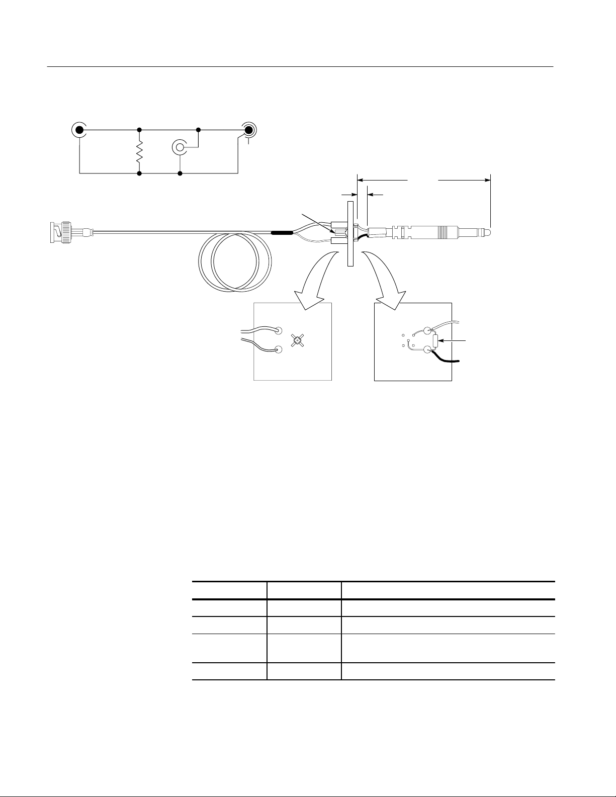
To adapt the single-ended signal source to the input of the AFTDS adapter,
assemble the calibration fixture shown in Figure 4 from the parts listed in
Table 3. Observe the following techniques:
H Use circuit board or prototype board to connect components.
H For good RF response, keep distances between connections to less than
6 mm (1/4 inch).
H Do not connect the braided wire of the Bantam connector. Fold back and
tape the braid so it is out of the way.
AFTDS Differential Signal Adapter Instructions
9
Performance Verification
Center
conductor
100 W
Shield White
50 W coaxial cable assembly (J1)
Black
wire
J2R1
wire
Probe connector (J2)
NC
J3J1
90 mm
(3.5 in)
13 mm
(.5 in.)
Bantam connector (J3)
R1
Figure 4: Schematic and layout diagrams for building the calibration fixture
The input and output connectors of the calibration fixture function as follows:
H The J1 input connects to the generator by means of a BNC connector.
H The J3 output connects to the input of the AFTDS adapter under test by
means of a Bantam plug.
H The J2 output connects to the oscilloscope probe for monitoring the J3
output.
T able 3: Calibration fixture parts list
Circuit number Part number Description
J1 175-1178-00 CABLE ASSY,RF 50 OHM COAX,20.0 L
J2 131-5031-00 CONNECTOR,PROBEPKG OF 25,COMP ACT
J3 012-1522-00 CABLE,INTCON SHLD CMPST ,;SD1,3 COND,36
L,BANT AM,3 COND PLUG BOTH ENDS
R1 322-3097-00 RES,FXD,FILM 100 OHM,1%,0.2W
10
Perform the verification procedures in order.
AFTDS Differential Signal Adapter Instructions

Attenuation
Performance Verification
1. Connect the input of the AFTDS adapter to the J3 output of the calibration
fixture.
2. Connect the output of the AFTDS adapter to the BNC-female-to-BNC-fe-
male adapter and then to the 50 W probe-tip-to-BNC adapter.
3. Connect a probe to channel 1 of the oscilloscope. Connect the probe tip to
the J2 output of the calibration fixture.
4. Connect the signal source to the J1 input of the calibration fixture.
5. Set the signal source for a 720 kHz square wave (700 ns wide pulses) of
amplitude. Enable the output.
1 V
p-p
6. Set the oscilloscope acquisition to >32 averages and set the measure function
to amplitude. Set the volts/division to 200 mV and the time/division to
400 ns.
7. Measure the exact amplitude of the input waveform with the measurement
function of the oscilloscope.
Rise Time
8. Move the probe tip to the probe-tip-to-BNC adapter on the output of the
AFTDS. Change the volts/division to 50 mV and read the amplitude on the
oscilloscope.
9. Calculate the the exact attenuation by dividing the input amplitude by the
output amplitude. Check that the attenuation is 5X and is within ± 5% (4.75
to 5.25).
1. Remove the BNC-female-to-BNC-female adapter and the 50 W probe-tip-to-
BNC adapter from the output of the AFTDS adapter.
2. Connect the output of the AFTDS adapter to the input of the oscilloscope.
3. Set the output of the generator for a fast edge (≤ 1 ns) 1 MHz square wave
(500 ns wide pulses) of 1 V
4. Set the oscilloscope volts/division to 250 mV and the time/division to 10 ns.
Set the measure function of the oscilloscope to rise time and read the rise
time on the oscilloscope.
5. Check that the rise time is ≤ 3.0 ns.
amplitude. Enable the output.
p-p
AFTDS Differential Signal Adapter Instructions
11
Performance Verification
Droop
1. Set the signal source for 143 kHz square wave (3.5 ms wide pulses) of 1 V
amplitude. Enable the output.
2. Set the oscilloscope volts/division to 250 mV and the time/division to
1.0 ms. Use the cursors on the oscilloscope to measure the droop of the
3.5 ms wide “high“ part of the waveform and the peak-peak amplitude of the
waveform.
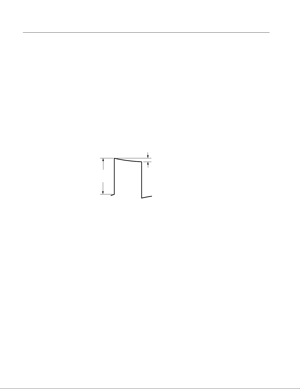
3. The percent droop is the magnitude of the droop divided by the step
amplitude (see Figure 5). Divide this number by 5 to obtain the droop per
700 ns.
4. Check that the droop is ≤ 2.0% per 700 ns.
Step
amplitude
Droop
Figure 5: Step amplitude and droop
12
AFTDS Differential Signal Adapter Instructions

Performance Verification
AFTDS Test Record
Photocopy this page and use it to record the performance test results for your
AFTDS Differential Signal Adapter.
AFTDS T est Record
Instrument Serial Number: Certificate Number:
Temperature: RH %:
Date of Calibration: Technician:
AFTDS Performance Test Minimum Incoming Outgoing Maximum
Attenuation: 5X ± 5%, –14 dB (50 kHz to 30 MHz)
Input amplitude
Output amplitude
Input B Output (attenuation factor)
Rise time: ≤ 3.0 ns N/A __________ __________ 3.0 ns
Droop: ≤ 2.0% for 700 ns
Droop amplitude
Step amplitude
Droop B output = % droop
% droop B 5 =
% droop per 700 ns
N/A
N/A
4.75
N/A
N/A
N/A
N/A
N/A
__________
B__________
= __________
__________
B__________
= __________
B 5
= __________
__________
B__________
= __________
__________
B__________
= __________
B 5
= __________
N/A
N/A
5.25
N/A
N/A
N/A
N/A
2.0%
AFTDS Differential Signal Adapter Instructions
13

Replaceable Parts and Accessories
2
1
5
3
4
14
Figure 6: Replaceable parts and standard accessories
CAUTION. To avoid damage to the AFTDS adapter, do not remove covers.
Removing the covers voids the factory warranty. The internal components of this
product are not user serviceable.
AFTDS Differential Signal Adapter Instructions

Replaceable Parts and Accessories
2
1
7
6
5
3
Figure 7: Optional accessories
4
AFTDS Differential Signal Adapter Instructions
15

Replaceable Parts and Accessories
Replaceable parts list
Fig. &
index
number
6– ADAPTER:AFTDS
–1 131–3627–01 1 CONTACT,ELEC:GOLD PLATED TIP 18359 P–6158–1
–2 205–0191–00 1 SHELL,ELEC CONN:BNC,ABS,DOVE GRAY 80009 205–0191–00
–3 334–9321–00 1 MARKER,IDENT:INSTRUMENT LABEL,AFTDS 80009 334–9321–00
–4 334–9354–00 1 MARKER,IDENT:SAFETY LABEL,AFTDS 80009 334–9354–00
–5 012–1520–00 1 CABLE, ADAPTER:SHLD,SDI,5.0 L,BANTAM TO
7–1 012–1469–00 1 CABLE,SIEMENS:CMPST,DIN41628,SDI,2 METER,
–2 012–1521–00 1 CABLE,INTCON:SHLD CMPST ,CRC,2
–3 012–1522–00 1 CABLE,INTCON:SHLD CMPST ,SD1,3 COND,36
–4 012–0104–00 1 CA ASSY,RF:COAXIAL,RFD,50 OHM,RG58/U,18.0
–5 015–0554–00 1 ADPTR,SMA,ELEC:FEMALE BNC TO MALE SMA 24931 29JP170–1
–6 011–0049–01 1 TERMN,COAXIAL:50 OHM,2W,BNC 24931 28A123–1
–7 103–0409–00 1 ADAPTER,CONN:ADAPTER,FEMALE,STR,FEMALE
Tektronix
part number
070–9483–00 1 MANUAL,TECH:INSTRUCTIONS,XBS,AFTDS,DP TK2548 070–9483–00
Serial no.
effective
Serial no.
discont’d
Qty Name & description Mfr. code Mfr. part number
Standard Accessories
TK2469 012–1520–00
SIEMENS TRIPLE BANANA
Optional Accessories
TK2469 012–1469–00
3 POS,MALE,SIEMENS BANANA PLUG BOTH ENDS
70674 BJR2M6
CONDUCTOR,72 .0,RJ11 PLUG TO BANTAM PLUG
70674 PJ–716
L,BANTAM,3 COND PLUG BOTH ENDS
74868 35001–1
L,MALE,BNC X FEMALE,BNC,
TK1857 TM5RL–88–JJ
RJ45 X FEMALE RJ45,PHONE JACK BOTH ENDS
Manufacturers cross index
Mfr.
code
18359 PYLON CO. INC. 51 NEWCOMB ST ATTLEBORO, MA 02703–1403
24931 BERG ELECTRONICS INC BERG ELECTRONICS RF/COAXIAL DIV
70674 ADC PRODUCTS 2680 BAYSHORE FRONT AGE RD.
74868 AMPHENOL CORP RF/MICROWAVE OPERA TIONS
80009 TEKTRONIX INC 14150 SW KARL BRAUN DR
TK1857 HIROSE ELECTRIC USA INC 2688 WESTHILLS COURT SIMI VALLEY, CA 93065–6235
TK2469 UNITREK CORPORATION 3000 LEWIS & CLARK HWY
TK2548 XEROX CORPORATION 14181 SW MILLIKAN WA Y BEAVERTON, OR 97005
16
Manufacturer Address City , state, zip code
2100 EARLYWOOD DR
PO BOX 547
SUITE 602
1 KENNEDY AVE
PO BOX 500
SUITE 2
FRANKLIN, IN 46131
MOUNTAIN VIEW, CA 94043
DANBURY, CT 06810–5803
BEAVERT ON, OR 97077–0001
VANCOUVER, W A 98661
AFTDS Differential Signal Adapter Instructions
 Loading...