

Page 1

x
AFG3000 Series
Arbitrary/Function Generators
ZZZ
Service Manual
*P071164005*
071-1640-05
Page 2

Page 3

Service Manual
AFG3000 Series
Arbitrary/Function Generators
071-1640-05
Warning
The servicing instructions are for use by qualified
personnel only. To avoid personal injury, do not
perform any servicing unless you are qualified to
do so. Refer to all safety summaries prior to
performing service.
www.tektronix.com
Page 4

Copyright © Tektronix. All rights reserved. Licensed software products are owned by Tektronix or its subsidiaries or
suppliers, and are protected by national copyright laws and international treaty provisions.
Tektronix products are covered by U.S. and foreign patents, issued and pending. Information in this publication
supersedes that in all previously published material. Specifications and price change privileges reserved.
TEKTRONIX and TEK are registered trademarks of Tektronix, Inc.
Contacting Tektronix
Tektronix, Inc.
14200 SW Karl Braun Drive
P.O. Box 500
Beaverton, OR 97077
USA
For product information, sales, service, and technical support:
In North America, call 1-800-833-9200.
Worldwide, visit www.tektronix.com to find contacts in your area.
Page 5

WARRANTY 16
Tektronix warrants that the product will be free from defects in materials and workmanship for a period of three (3)
years from the date of original purchase from an authorized Tektronix distributor. If the product proves defective
during this warranty period, Tektronix, at its option, either will repair the defective product without charge for parts
and labor, or will provide a replacement in exchange for the defective product. Batteries are excluded from this
warranty. Parts, modules and replacement products used by Tektronix for warranty work may be new or reconditioned
to like new performance. All replaced parts, modules and products become the property of Tektronix.
In order to obtain service under this warranty, Customer must notify Tektronix of the defect before the expiration of
the warranty period and make suitable arrangements for the performance of service. Customer shall be responsible for
packaging and shipping the defective product to the service center designated by Tektronix, shipping charges prepaid,
and with a copy of customer proof of purchase. Tektronix shall pay for the return of the product to Customer if the
shipment is to a location within the country in which the Tektronix service center is located. Customer shall be
responsible for paying all shipping charges, duties, taxes, and any other charges for products returned to any other
locations.
This warranty shall not apply to any defect, failure or damage caused by improper use or improper or inadequate
maintenance and care. Tektronix shall not be obligated to furnish service under this warranty a) to repair damage
resulting from attempts by personnel other than Tektronix representatives to install, repair or service the product; b) to
repair damage resulting from improper use or connection to incompatible equipment; c) to repair any damage or
malfunction caused by the use of non-Tektronix supplies; or d) to service a product that has been modified or integrated
with other products when the effect of such modification or integration increases the time or difficulty of servicing the
product.
THIS WARRANTY IS GIVEN BY TEKTRONIX WITH RESPECT TO THE PRODUCT IN LIEU OF ANY
OTHER WARRANTIES, EXPRESS OR IMPLIED. TEKTRONIX AND ITS VENDORS DISCLAIM ANY
IMPLIED WARRANTIES OF MERCHANTABILITY OR FITNESS FOR A PARTICULAR PURPOSE.
TEKTRONIX' RESPONSIBILITY TO REPAIR OR REPLACE DEFECTIVE PRODUCTS IS THE SOLE
AND EXCLUSIVE REMEDY PROVIDED TO THE CUSTOMER FOR BREACH OF THIS WARRANTY.
TEKTRONIX AND ITS VENDORS WILL NOT BE LIABLE FOR ANY INDIRECT, SPECIAL,
INCIDENTAL, OR CONSEQUENTIAL DAMAGES IRRESPECTIVE OF WHETHER TEKTRONIX OR
THE VENDOR HAS ADVANCE NOTICE OF THE POSSIBILITY OF SUCH DAMAGES.
Page 6

Page 7

Table of Contents
Specifications
Operating Information
General Safety Summary . . . . . . . . . . . . . . . . . . . . . . . . . . . . . . . . . . . . . . . . . . . . . . vii
Service Safety Summary . . . . . . . . . . . . . . . . . . . . . . . . . . . . . . . . . . . . . . . . . . . . . . . ix
Preface . . . . . . . . . . . . . . . . . . . . . . . . . . . . . . . . . . . . . . . . . . . . . . . . . . . . . . . . . . . . . xi
Finding Other Information . . . . . . . . . . . . . . . . . . . . . . . . . . . . . . . . . . . . . . . . . . . . . . . xii
Manual Conventions . . . . . . . . . . . . . . . . . . . . . . . . . . . . . . . . . . . . . . . . . . . . . . . . . . . xii
Introduction . . . . . . . . . . . . . . . . . . . . . . . . . . . . . . . . . . . . . . . . . . . . . . . . . . . . . . . . xiii
Performance Verification Procedures . . . . . . . . . . . . . . . . . . . . . . . . . . . . . . . . . . . . . xiii
Strategy for Servicing . . . . . . . . . . . . . . . . . . . . . . . . . . . . . . . . . . . . . . . . . . . . . . . . . xiii
Tektronix Service Offerings. . . . . . . . . . . . . . . . . . . . . . . . . . . . . . . . . . . . . . . . . . . . . xiv
Specifications . . . . . . . . . . . . . . . . . . . . . . . . . . . . . . . . . . . . . . . . . . . . . . . . . . . . . . . 1-1
Performance Conditions. . . . . . . . . . . . . . . . . . . . . . . . . . . . . . . . . . . . . . . . . . . . . . . . 1-1
Electrical . . . . . . . . . . . . . . . . . . . . . . . . . . . . . . . . . . . . . . . . . . . . . . . . . . . . . . . . . . . 1-1
Inputs/Outputs . . . . . . . . . . . . . . . . . . . . . . . . . . . . . . . . . . . . . . . . . . . . . . . . . . . . . . 1-11
General . . . . . . . . . . . . . . . . . . . . . . . . . . . . . . . . . . . . . . . . . . . . . . . . . . . . . . . . . . . . 1-12
Operating Basics . . . . . . . . . . . . . . . . . . . . . . . . . . . . . . . . . . . . . . . . . . . . . . . . . . . . 2-1
General Features . . . . . . . . . . . . . . . . . . . . . . . . . . . . . . . . . . . . . . . . . . . . . . . . . . . . . 2-1
Installation . . . . . . . . . . . . . . . . . . . . . . . . . . . . . . . . . . . . . . . . . . . . . . . . . . . . . . . . . . 2-2
Protect Your Instrument from Misuse . . . . . . . . . . . . . . . . . . . . . . . . . . . . . . . . . . . . . 2-3
Floating Ground . . . . . . . . . . . . . . . . . . . . . . . . . . . . . . . . . . . . . . . . . . . . . . . . . . . . . . 2-4
Protect Your DUT . . . . . . . . . . . . . . . . . . . . . . . . . . . . . . . . . . . . . . . . . . . . . . . . . . . . 2-5
Powering the Instrument On and Off. . . . . . . . . . . . . . . . . . . . . . . . . . . . . . . . . . . . . . 2-6
Self Test and Self Calibration . . . . . . . . . . . . . . . . . . . . . . . . . . . . . . . . . . . . . . . . . . . 2-7
Getting Acquainted with Your Instrument . . . . . . . . . . . . . . . . . . . . . . . . . . . . . . . . . . 2-8
Screen Interface . . . . . . . . . . . . . . . . . . . . . . . . . . . . . . . . . . . . . . . . . . . . . . . . . . . . . 2-10
Theory of Operation
Theory of Operation . . . . . . . . . . . . . . . . . . . . . . . . . . . . . . . . . . . . . . . . . . . . . . . . . 3-1
Overview . . . . . . . . . . . . . . . . . . . . . . . . . . . . . . . . . . . . . . . . . . . . . . . . . . . . . . . . . . . 3-1
Platform . . . . . . . . . . . . . . . . . . . . . . . . . . . . . . . . . . . . . . . . . . . . . . . . . . . . . . . . . . . . 3-3
Generator Section. . . . . . . . . . . . . . . . . . . . . . . . . . . . . . . . . . . . . . . . . . . . . . . . . . . . . 3-4
Performance Verification
Performance Verification . . . . . . . . . . . . . . . . . . . . . . . . . . . . . . . . . . . . . . . . . . . . . 4-1
Self Tests . . . . . . . . . . . . . . . . . . . . . . . . . . . . . . . . . . . . . . . . . . . . . . . . . . . . . . . . . . . 4-1
Performance Tests . . . . . . . . . . . . . . . . . . . . . . . . . . . . . . . . . . . . . . . . . . . . . . . . . . . . 4-3
Test Record . . . . . . . . . . . . . . . . . . . . . . . . . . . . . . . . . . . . . . . . . . . . . . . . . . . . . . . . . 4-5
Frequency/Period Test . . . . . . . . . . . . . . . . . . . . . . . . . . . . . . . . . . . . . . . . . . . . . . . . 4-20
Amplitude Test . . . . . . . . . . . . . . . . . . . . . . . . . . . . . . . . . . . . . . . . . . . . . . . . . . . . . . 4-21
DC Offset Test . . . . . . . . . . . . . . . . . . . . . . . . . . . . . . . . . . . . . . . . . . . . . . . . . . . . . . 4-23
AFG3000 Series Arbitrary/Function Generators Service Manual i
Page 8

Table of Contents
Adjustment Procedures
AC Flatness Test . . . . . . . . . . . . . . . . . . . . . . . . . . . . . . . . . . . . . . . . . . . . . . . . . . . . . 4-26
Harmonics Distortion Test . . . . . . . . . . . . . . . . . . . . . . . . . . . . . . . . . . . . . . . . . . . . . 4-28
Total Harmonic Distortion Test. . . . . . . . . . . . . . . . . . . . . . . . . . . . . . . . . . . . . . . . . . 4-30
Spurious Test . . . . . . . . . . . . . . . . . . . . . . . . . . . . . . . . . . . . . . . . . . . . . . . . . . . . . . . . 4-32
Rise-Fall time Test . . . . . . . . . . . . . . . . . . . . . . . . . . . . . . . . . . . . . . . . . . . . . . . . . . . 4-35
Adjustment Procedures . . . . . . . . . . . . . . . . . . . . . . . . . . . . . . . . . . . . . . . . . . . . . . . 5-1
Purpose . . . . . . . . . . . . . . . . . . . . . . . . . . . . . . . . . . . . . . . . . . . . . . . . . . . . . . . . . . . . .5-1
Equipment Required . . . . . . . . . . . . . . . . . . . . . . . . . . . . . . . . . . . . . . . . . . . . . . . . . . . 5-2
Performance Conditions . . . . . . . . . . . . . . . . . . . . . . . . . . . . . . . . . . . . . . . . . . . . . . . . 5-3
Enable the Service Mode. . . . . . . . . . . . . . . . . . . . . . . . . . . . . . . . . . . . . . . . . . . . . . . . 5-3
Save Menu. . . . . . . . . . . . . . . . . . . . . . . . . . . . . . . . . . . . . . . . . . . . . . . . . . . . . . . . . . . 5-3
Clear CAL Data Menu . . . . . . . . . . . . . . . . . . . . . . . . . . . . . . . . . . . . . . . . . . . . . . . . . 5-3
Reference Clock . . . . . . . . . . . . . . . . . . . . . . . . . . . . . . . . . . . . . . . . . . . . . . . . . . . . . . 5-4
LF Adjustment. . . . . . . . . . . . . . . . . . . . . . . . . . . . . . . . . . . . . . . . . . . . . . . . . . . . . . . . 5-5
Flatness Adjustment . . . . . . . . . . . . . . . . . . . . . . . . . . . . . . . . . . . . . . . . . . . . . . . . . . . 5-6
Spurious Adjustment . . . . . . . . . . . . . . . . . . . . . . . . . . . . . . . . . . . . . . . . . . . . . . . . . . . 5-8
Trigger Delay Adjustment. . . . . . . . . . . . . . . . . . . . . . . . . . . . . . . . . . . . . . . . . . . . . . 5-10
Setting the Serial Number . . . . . . . . . . . . . . . . . . . . . . . . . . . . . . . . . . . . . . . . . . . . . . 5-12
Setting the MAC Address . . . . . . . . . . . . . . . . . . . . . . . . . . . . . . . . . . . . . . . . . . . . . . 5-12
Maintenance
Maintenance . . . . . . . . . . . . . . . . . . . . . . . . . . . . . . . . . . . . . . . . . . . . . . . . . . . . . . . . 6-1
Preparation . . . . . . . . . . . . . . . . . . . . . . . . . . . . . . . . . . . . . . . . . . . . . . . . . . . . . . . . . . 6-1
Preventing ESD. . . . . . . . . . . . . . . . . . . . . . . . . . . . . . . . . . . . . . . . . . . . . . . . . . . . . . . 6-1
Inspection and Cleaning . . . . . . . . . . . . . . . . . . . . . . . . . . . . . . . . . . . . . . . . . . . . . . . . 6-2
Removal and Installation Procedures . . . . . . . . . . . . . . . . . . . . . . . . . . . . . . . . . . . . 6-7
Adjustment after Repair . . . . . . . . . . . . . . . . . . . . . . . . . . . . . . . . . . . . . . . . . . . . . . . . 6-7
List of Modules . . . . . . . . . . . . . . . . . . . . . . . . . . . . . . . . . . . . . . . . . . . . . . . . . . . . . . . 6-7
Summary of Procedures . . . . . . . . . . . . . . . . . . . . . . . . . . . . . . . . . . . . . . . . . . . . . . . . 6-8
Tools Required . . . . . . . . . . . . . . . . . . . . . . . . . . . . . . . . . . . . . . . . . . . . . . . . . . . . . . . 6-8
Flip Feet. . . . . . . . . . . . . . . . . . . . . . . . . . . . . . . . . . . . . . . . . . . . . . . . . . . . . . . . . . . . . 6-9
Front-Panel knob . . . . . . . . . . . . . . . . . . . . . . . . . . . . . . . . . . . . . . . . . . . . . . . . . . . . . 6-10
Rear Case. . . . . . . . . . . . . . . . . . . . . . . . . . . . . . . . . . . . . . . . . . . . . . . . . . . . . . . . . . . 6-10
Top Cover . . . . . . . . . . . . . . . . . . . . . . . . . . . . . . . . . . . . . . . . . . . . . . . . . . . . . . . . . . 6-12
Front Case . . . . . . . . . . . . . . . . . . . . . . . . . . . . . . . . . . . . . . . . . . . . . . . . . . . . . . . . . . 6-12
A75 Front-Panel Board . . . . . . . . . . . . . . . . . . . . . . . . . . . . . . . . . . . . . . . . . . . . . . . . 6-13
Display Module . . . . . . . . . . . . . . . . . . . . . . . . . . . . . . . . . . . . . . . . . . . . . . . . . . . . . . 6-14
Output Board (AFG310x, AFG325x) . . . . . . . . . . . . . . . . . . . . . . . . . . . . . . . . . . . . . 6-14
Separation of Rear Module and Main Chassis . . . . . . . . . . . . . . . . . . . . . . . . . . . . . . 6-15
Inverter . . . . . . . . . . . . . . . . . . . . . . . . . . . . . . . . . . . . . . . . . . . . . . . . . . . . . . . . . . . .6-17
Fan. . . . . . . . . . . . . . . . . . . . . . . . . . . . . . . . . . . . . . . . . . . . . . . . . . . . . . . . . . . . . . . . 6-18
Power Supply . . . . . . . . . . . . . . . . . . . . . . . . . . . . . . . . . . . . . . . . . . . . . . . . . . . . . . . 6-19
A72 CPU Board . . . . . . . . . . . . . . . . . . . . . . . . . . . . . . . . . . . . . . . . . . . . . . . . . . . . . 6-20
A82 BNC Insulator Board. . . . . . . . . . . . . . . . . . . . . . . . . . . . . . . . . . . . . . . . . . . . . . 6-21
Generator Board . . . . . . . . . . . . . . . . . . . . . . . . . . . . . . . . . . . . . . . . . . . . . . . . . . . . . 6-22
A81 BNC Insulator Board, BNC Bracket . . . . . . . . . . . . . . . . . . . . . . . . . . . . . . . . . . 6-23
Troubleshooting . . . . . . . . . . . . . . . . . . . . . . . . . . . . . . . . . . . . . . . . . . . . . . . . . . . . 6-25
ii AFG3000 Series Arbitrary/Function Generators Service Manual
Page 9

Diagrams
Replaceable Parts List
Table of Contents
Required Tools and Equipment . . . . . . . . . . . . . . . . . . . . . . . . . . . . . . . . . . . . . . . . . 6-25
Troubleshooting Tree . . . . . . . . . . . . . . . . . . . . . . . . . . . . . . . . . . . . . . . . . . . . . . . . . 6-25
Diagnostics. . . . . . . . . . . . . . . . . . . . . . . . . . . . . . . . . . . . . . . . . . . . . . . . . . . . . . . . . 6-28
Calibration . . . . . . . . . . . . . . . . . . . . . . . . . . . . . . . . . . . . . . . . . . . . . . . . . . . . . . . . . 6-29
Error Codes . . . . . . . . . . . . . . . . . . . . . . . . . . . . . . . . . . . . . . . . . . . . . . . . . . . . . . . . 6-30
Diagrams . . . . . . . . . . . . . . . . . . . . . . . . . . . . . . . . . . . . . . . . . . . . . . . . . . . . . . . . . . 7-1
Replaceable Parts List . . . . . . . . . . . . . . . . . . . . . . . . . . . . . . . . . . . . . . . . . . . . . . . 8-1
Parts Ordering Information . . . . . . . . . . . . . . . . . . . . . . . . . . . . . . . . . . . . . . . . . . . . . 8-1
Using the Replaceable Parts List . . . . . . . . . . . . . . . . . . . . . . . . . . . . . . . . . . . . . . . . . 8-2
AFG3000 Series Arbitrary/Function Generators Service Manual iii
Page 10

List of Tables
List of Tables
Table 1-1: Operation mode . . . . . . . . . . . . . . . . . . . . . . . . . . . . . . . . . . . . . . . . . . . . 1-1
Table 1-2: Waveforms . . . . . . . . . . . . . . . . . . . . . . . . . . . . . . . . . . . . . . . . . . . . . . . . 1-2
Table 1-3: Frequency and period . . . . . . . . . . . . . . . . . . . . . . . . . . . . . . . . . . . . . . . 1-2
Table 1-4: Phase (except DC, Noise, and Pulse) . . . . . . . . . . . . . . . . . . . . . . . . . . . 1-4
Table 1-5: Lead delay (pulse) . . . . . . . . . . . . . . . . . . . . . . . . . . . . . . . . . . . . . . . . . . 1-4
Table 1-6: Amplitude . . . . . . . . . . . . . . . . . . . . . . . . . . . . . . . . . . . . . . . . . . . . . . . . . 1-4
Table 1-7: DC offset . . . . . . . . . . . . . . . . . . . . . . . . . . . . . . . . . . . . . . . . . . . . . . . . . . 1-5
Table 1-8: Internal noise add . . . . . . . . . . . . . . . . . . . . . . . . . . . . . . . . . . . . . . . . . . 1-5
Table 1-9: Output characteristics . . . . . . . . . . . . . . . . . . . . . . . . . . . . . . . . . . . . . . . 1-6
Table 1-10: Modulation . . . . . . . . . . . . . . . . . . . . . . . . . . . . . . . . . . . . . . . . . . . . . . . 1-9
Table 1-11: Front panel . . . . . . . . . . . . . . . . . . . . . . . . . . . . . . . . . . . . . . . . . . . . . . 1-11
Table 1-12: Rear panel . . . . . . . . . . . . . . . . . . . . . . . . . . . . . . . . . . . . . . . . . . . . . . . 1-12
Table 1-13: System characteristics . . . . . . . . . . . . . . . . . . . . . . . . . . . . . . . . . . . . . 1-12
Table 1-14: Power . . . . . . . . . . . . . . . . . . . . . . . . . . . . . . . . . . . . . . . . . . . . . . . . . . . 1-13
Table 1-15: Environmental . . . . . . . . . . . . . . . . . . . . . . . . . . . . . . . . . . . . . . . . . . . 1-13
Table 2-1: General features . . . . . . . . . . . . . . . . . . . . . . . . . . . . . . . . . . . . . . . . . . . . 2-1
Table 3-1: Combination of circuit boards used in each model . . . . . . . . . . . . . . . 3-1
Table 4-1: Performance test items . . . . . . . . . . . . . . . . . . . . . . . . . . . . . . . . . . . . . . 4-3
Table 4-2: Test equipment . . . . . . . . . . . . . . . . . . . . . . . . . . . . . . . . . . . . . . . . . . . . . 4-4
Table 5-1: Adjustments performed after repair . . . . . . . . . . . . . . . . . . . . . . . . . . . 5-1
Table 5-2: Test equipment . . . . . . . . . . . . . . . . . . . . . . . . . . . . . . . . . . . . . . . . . . . . . 5-2
Table 6-1: External inspection check list . . . . . . . . . . . . . . . . . . . . . . . . . . . . . . . . . 6-3
Table 6-2: Internal inspection check list . . . . . . . . . . . . . . . . . . . . . . . . . . . . . . . . . 6-4
Table 6-3: Required equipment . . . . . . . . . . . . . . . . . . . . . . . . . . . . . . . . . . . . . . . 6-25
Table 6-4: Error codes . . . . . . . . . . . . . . . . . . . . . . . . . . . . . . . . . . . . . . . . . . . . . . . 6-30
iv AFG3000 Series Arbitrary/Function Generators Service Manual
Page 11

List of Figures
List of Figures
Figure 1-1: AFG3000 Series dimensions . . . . . . . . . . . . . . . . . . . . . . . . . . . . . . . . 1-14
Figure 1-2: RM3100 Rackmount dimensions . . . . . . . . . . . . . . . . . . . . . . . . . . . . 1-14
Figure 2-1: Front size . . . . . . . . . . . . . . . . . . . . . . . . . . . . . . . . . . . . . . . . . . . . . . . . 2-2
Figure 2-2: Output and Input connectors . . . . . . . . . . . . . . . . . . . . . . . . . . . . . . . . 2-3
Figure 2-3: Fuse adapter . . . . . . . . . . . . . . . . . . . . . . . . . . . . . . . . . . . . . . . . . . . . . 2-3
Figure 2-4: Grounding equivalent circuit . . . . . . . . . . . . . . . . . . . . . . . . . . . . . . . . 2-4
Figure 2-5: Front-panel controls . . . . . . . . . . . . . . . . . . . . . . . . . . . . . . . . . . . . . . . 2-8
Figure 2-6: Rear panel . . . . . . . . . . . . . . . . . . . . . . . . . . . . . . . . . . . . . . . . . . . . . . . 2-9
Figure 2-7: Screen interface . . . . . . . . . . . . . . . . . . . . . . . . . . . . . . . . . . . . . . . . . . 2-10
Figure 3-1: AFG3000 Series block diagram . . . . . . . . . . . . . . . . . . . . . . . . . . . . . . 3-2
Figure 4-1: Frequency/Period tests . . . . . . . . . . . . . . . . . . . . . . . . . . . . . . . . . . . . 4-20
Figure 4-2: 50 Ω terminator accuracy . . . . . . . . . . . . . . . . . . . . . . . . . . . . . . . . . . 4-21
Figure 4-3: Amplitude tests . . . . . . . . . . . . . . . . . . . . . . . . . . . . . . . . . . . . . . . . . . 4-21
Figure 4-4: 50 Ω terminator accuracy . . . . . . . . . . . . . . . . . . . . . . . . . . . . . . . . . . 4-23
Figure 4-5: DC offset tests . . . . . . . . . . . . . . . . . . . . . . . . . . . . . . . . . . . . . . . . . . . 4-24
Figure 4-6: AC flatness tests . . . . . . . . . . . . . . . . . . . . . . . . . . . . . . . . . . . . . . . . . 4-26
Figure 4-7: Harmonic distortion tests . . . . . . . . . . . . . . . . . . . . . . . . . . . . . . . . . . 4-28
Figure 4-8: Total Harmonic distortion tests . . . . . . . . . . . . . . . . . . . . . . . . . . . . . 4-30
Figure 4-9: Spurious tests . . . . . . . . . . . . . . . . . . . . . . . . . . . . . . . . . . . . . . . . . . . . 4-32
Figure 4-10: Rise-Fall time tests . . . . . . . . . . . . . . . . . . . . . . . . . . . . . . . . . . . . . . 4-35
Figure 5-1: Reference Clock adjustment . . . . . . . . . . . . . . . . . . . . . . . . . . . . . . . . 5-4
Figure 5-2: LF adjustment . . . . . . . . . . . . . . . . . . . . . . . . . . . . . . . . . . . . . . . . . . . . 5-5
Figure 5-3: Flatness adjustment . . . . . . . . . . . . . . . . . . . . . . . . . . . . . . . . . . . . . . . 5-6
Figure 5-4: Spurious adjustment . . . . . . . . . . . . . . . . . . . . . . . . . . . . . . . . . . . . . . . 5-8
Figure 5-5: Trigger delay adjustment . . . . . . . . . . . . . . . . . . . . . . . . . . . . . . . . . . 5-10
Figure 6-1: Disassembly order . . . . . . . . . . . . . . . . . . . . . . . . . . . . . . . . . . . . . . . . . 6-8
Figure 6-2: Removing and installing the flip feet . . . . . . . . . . . . . . . . . . . . . . . . . . 6-9
Figure 6-3: Rear case removal . . . . . . . . . . . . . . . . . . . . . . . . . . . . . . . . . . . . . . . . 6-10
Figure 6-4: Pasting the urethane foam gaskets . . . . . . . . . . . . . . . . . . . . . . . . . . 6-11
Figure 6-5: Top cover removal . . . . . . . . . . . . . . . . . . . . . . . . . . . . . . . . . . . . . . . 6-12
Figure 6-6: Front case removal . . . . . . . . . . . . . . . . . . . . . . . . . . . . . . . . . . . . . . . 6-13
Figure 6-7: A75 front-panel board removal . . . . . . . . . . . . . . . . . . . . . . . . . . . . . 6-13
Figure 6-8: Display module removal . . . . . . . . . . . . . . . . . . . . . . . . . . . . . . . . . . . 6-14
Figure 6-9: Output board removal . . . . . . . . . . . . . . . . . . . . . . . . . . . . . . . . . . . . 6-15
Figure 6-10: Separation of the rear module and main chassis . . . . . . . . . . . . . . 6-16
Figure 6-11: Pull out the rear module . . . . . . . . . . . . . . . . . . . . . . . . . . . . . . . . . . 6-16
Figure 6-12: Inverter removal . . . . . . . . . . . . . . . . . . . . . . . . . . . . . . . . . . . . . . . . 6-17
Figure 6-13: Inverter installation . . . . . . . . . . . . . . . . . . . . . . . . . . . . . . . . . . . . . 6-17
Figure 6-14: Fan removal . . . . . . . . . . . . . . . . . . . . . . . . . . . . . . . . . . . . . . . . . . . . 6-18
Figure 6-15: Power supply removal . . . . . . . . . . . . . . . . . . . . . . . . . . . . . . . . . . . 6-19
Figure 6-16: Remove the BNC connectors . . . . . . . . . . . . . . . . . . . . . . . . . . . . . . 6-20
AFG3000 Series Arbitrary/Function Generators Service Manual v
Page 12

List of Figures
Figure 6-17: CPU board removal . . . . . . . . . . . . . . . . . . . . . . . . . . . . . . . . . . . . . . 6-21
Figure 6-18: Generator board removal . . . . . . . . . . . . . . . . . . . . . . . . . . . . . . . . . 6-22
Figure 6-19: A81 BNC Insulator board and BNC bracket removal . . . . . . . . . . 6-23
Figure 6-20: Platform troubleshooting procedure . . . . . . . . . . . . . . . . . . . . . . . . 6-26
Figure 6-21: Generator troubleshooting procedure . . . . . . . . . . . . . . . . . . . . . . . 6-27
Figure 7-1: Interconnection for AFG3011 . . . . . . . . . . . . . . . . . . . . . . . . . . . . . . . . 7-1
Figure 7-2: Interconnection for AFG302xB . . . . . . . . . . . . . . . . . . . . . . . . . . . . . . . 7-2
Figure 7-3: Interconnection for AFG310x and AFG325x . . . . . . . . . . . . . . . . . . . 7-3
Figure 8-1: Exploded diagram . . . . . . . . . . . . . . . . . . . . . . . . . . . . . . . . . . . . . . . . . 8-7
Figure 8-2: Rear modules . . . . . . . . . . . . . . . . . . . . . . . . . . . . . . . . . . . . . . . . . . . . 8-10
vi AFG3000 Series Arbitrary/Function Generators Service Manual
Page 13

General Safety Summary
Review the following safety precautions to avoid injury and prevent damage to this
product or any products connected to it. To avoid potential hazards, use this
product only as specified.
Only qualified personnel should perform service procedures.
To Avoid Fire or
Personal Injury
Use Proper Power Cord. Use only the power cord specified for this product and
certified for the country of use.
Ground the Product. This product is grounded through the grounding conductor of
the power cord. To avoid electric shock, the grounding conductor must be
connected to earth ground. Before making connections to the input or output
terminals of the product, ensure that the product is properly grounded.
Observe All Terminal Ratings. To avoid fire or shock hazard, observe all ratings and
markings on the product. Consult the product manual for further ratings
information before making connections to the product.
The common terminal is at ground potential. Do not connect the common terminal
to elevated voltages.
Do not apply a potential to any terminal, including the common terminal, that
exceeds the maximum rating of that terminal.
Do Not Operate Without Covers. Do not operate this product with covers or panels
removed.
Avoid Exposed Circuitry. Do not touch exposed connections and components when
power is present.
Do Not Operate With Suspected Failures. If you suspect there is damage to this
product, have it inspected by qualified service personnel.
Do Not Operate in Wet/Damp Conditions.
Do Not Operate in an Explosive Atmosphere.
Keep Product Surfaces Clean and Dry.
Provide Proper Ventilation. Refer to the manual’s installation instructions for
details on installing the product so it has proper ventilation.
AFG3000 Series Arbitrary/Function Generators Service Manual vii
Page 14
General Safety Summary
WARNING
High Voltage
Protective Ground
(Earth) Terminal
CAUTION
Refer to Manual
Double
Insulated
Symbols and Terms
Terms in this Manual. These terms may appear in this manual:
WARNING. Warning statements identify conditions or practices that could result
in injury or loss of life.
CAUTION. Caution statements identify conditions or practices that could result in
damage to this product or other property.
Terms on the Product. These terms may appear on the product:
DANGER indicates an injury hazard immediately accessible as you read the
marking.
WARNING indicates an injury hazard not immediately accessible as you read the
marking.
CAUTION indicates a hazard to property including the product.
Symbols on the Product. The following symbols may appear on the product:
viii AFG3000 Series Arbitrary/Function Generators Service Manual
Page 15

Service Safety Summary
Only qualified personnel should perform service procedures. Read this Service
Safety Summary and the General Safety Summary before performing any service
procedures.
Do Not Service Alone. Do not perform internal service or adjustments of this
product unless another person capable of rendering first aid and resuscitation is
present.
Disconnect Power. To avoid electric shock, disconnect the mains power by means
of the power cord or, if provided, the power switch.
Use Care When Servicing With Power On. Dangerous voltages or currents may exist
in this product. Disconnect power, remove battery (if applicable), and disconnect
test leads before removing protective panels, soldering, or replacing components.
To avoid electric shock, do not touch exposed connections.
AFG3000 Series Arbitrary/Function Generators Service Manual ix
Page 16

Service Safety Summary
x AFG3000 Series Arbitrary/Function Generators Service Manual
Page 17

Preface
This manual provides instructions to verify the performance of, calibrate,
troubleshoot, and repair the arbitrary/function generators to the module level.
Unless noted otherwise, the term “AFG3000 Series” refers to the models in the
AFG3011, AFG3021B, AFG3022B, AFG3101, AFG3102, AFG3251, and
AFG3252 arbitrary/function generators.
NOTE. If your instrument is AFG3021 or AFG3022, refer to the service manual,
Tektronix part number 071-1640-02.
The manual consists of the following sections:
Specifications contains a description of the arbitrary/function generator and the
characteristics that apply to it.
Operating Information includes general information and operating
instructions.
Theory of Operation contains circuit descriptions that support service to the
module level.
Performance Verification contains procedures for confirming that the
arbitrary/function generator functions properly and meets warranted limits.
Adjustment Procedures contains information that you need to manually adjust
the arbitrary/function generator so that it meets specifications.
Maintenance contains information and procedures for performing preventive
and corrective maintenance of the arbitrary/function generator. These
instructions include cleaning, module removal and installation, and fault
isolation to the module.
Diagrams contains interconnection diagrams.
Replaceable Parts List includes a table of all replaceable modules, their
descriptions, and their Tektronix part numbers.
AFG3000 Series Arbitrary/Function Generators Service Manual xi
Page 18
Preface
Finding Other Information
This manual mainly focuses on the performance verification, troubleshooting and
maintenance of the arbitrary/function generator. See the following list for other
documents supporting the arbitrary/function generator. All documents except
Built-in Help are on the AFG3000 Series Product Documents CD-ROM that
shipped with instrument.
Document name Description
AFG3000 Series Quick Start User Manual A quick reference to major features of the instrument and how they operate. It also provides
several tutorials to familiarize you with basic instrument features.
AFG3000 Series Programmer Manual An encyclopedia of topics that describe the arbitrary/function generator interface and
features, and gives background information on how to use them. It provides Menu
Structures, User Interface, and Programming Information.
AFG3000 Series Built-in Help A built-in help system, integrated with the User Interface application that ships with this
product. The help is preinstalled in the instrument.
Manual Conventions
Modules
Safety
This manual uses certain conventions that you should become familiar with.
Some sections of the manual contain procedures for you to perform. To keep those
instructions clear and consistent, this manual uses the following conventions:
Front-panel controls and menu names appear in the same case (initial capitals,
all uppercase, and so on) in the manual as is used on the arbitrary/function
generator front-panel and menus. Front-panel labels are all upper case letters
(for example, MENU, SELECT, PULSE GEN, and so on).
Instruction steps are numbered unless there is only one step.
Throughout this manual, any replaceable component, assembly, or part of the
arbitrary/function generator is referred to generically as a module. In general, a
module is an assembly (like a circuit board), rather than a component (like a
resistor or an integrated circuit). Sometimes a single component is a module; for
example, the chassis of the arbitrary/function generator is a module.
Symbols and terms related to safety appear in the Safety Summary near the
beginning of this manual.
xii AFG3000 Series Arbitrary/Function Generators Service Manual
Page 19

Introduction
This manual contains information that is needed to properly service the AFG3000
Series Arbitrary/Function Generators as well as general information that is critical
to safe and effective servicing.
To prevent personal injury or damage to the arbitrary/function generator, consider
the following before attempting service:
The procedures in this manual should be performed only by a qualified service
person.
Read the General Safety Summary on page vii and the Service Safety Summary,
beginning on page ix.
Read Installation in Operating Basics on page 2-2.
When using this manual for servicing, be sure to follow all warnings, cautions, and
notes.
Performance Verification Procedures
Strategy for Servicing
The performance check described in the Performance Verification section should
be done every 12 months. In addition, a performance check is recommended after
module replacement.
If the AFG3000 Series does not meet performance criteria, repair is necessary.
Throughout this manual, the term, module, refers to any field-replaceable
component, assembly, or part of the arbitrary/function generator.
This manual contains the information needed for periodic maintenance of the
arbitrary/function generator. Further, it contains information for corrective
maintenance down to the module level. To isolate a failure to a module, use the
troubleshooting procedures found in the Maintenance section. To remove and
replace any failed module, follow the instructions in the Removal and Installation
Procedures subsection. After isolating a faulty module, replace it with a
fully-tested module obtained from the factory. The Replaceable Parts List section
contains part number and ordering information for all replaceable modules.
AFG3000 Series Arbitrary/Function Generators Service Manual xiii
Page 20

Introduction
Tektronix Service Offerings
Tektronix provides service to cover repair under warranty as well as other services
that may provide a cost-effective answer to your service needs.
Tektronix service technicians are well trained to service the arbitrary/function
generator. They have access to the latest information on improvements to the
AFG3000 Series as well as new options.
Warranty Repair Service
Self Service
For More Information
Tektronix warrants this product for three years from date of purchase. The warranty
appears at the front of this manual. Tektronix technicians provide warranty service
at most Tektronix service locations.
Tektronix supports repair to the replaceable part and module level.
Contact your local Tektronix service center or sales engineer for more information
on any repair or adjustment service.
xiv AFG3000 Series Arbitrary/Function Generators Service Manual
Page 21

Specifications
Page 22

Page 23
Specifications
Performance Conditions
These specifications apply to all AFG3000 Series Arbitrary/Function Generators.
All specifications are guaranteed unless labeled “typical”. Typical specifications
are provided for your convenience but are not guaranteed.
Specifications that are check marked with the ✔ symbol are checked directly (or
indirectly) in the Performance Verification section.
All specifications apply to the arbitrary/function generator unless noted otherwise.
These specifications are valid under the following conditions:
The performance limits in this specification are valid with these conditions:
The instrument must have been calibrated/adjusted at an ambient temperature
between +20
The instrument must be operating at an ambient temperature between 0 °C and
°C.
+50
°C and +30 °C.
The instrument must have had a warm-up period of at least 20 minutes.
The instrument must be in an environment with temperature, altitude, and
humidity within the operating limits described in these specifications.
Electrical
Table 1-1: Operation mode
Characteristics Description
Run mode Continuous, Modulation, Sweep, and Burst
Burst count 1 to 1,000,000 cycles or Infinite
Internal trigger rate 1.000 μs to 500.0 s
AFG3000 Series Arbitrary/Function Generators Service Manual 1-1
Page 24

Specifications
Table 1-2: Waveforms
Characteristics Description
Standard Sine, Square, Pulse, Ramp, More (Sin(x)/x, Noise, DC, Gaussian, Lorentz, Exponential Rise,
Exponential Decay, and Haversine)
Arbitrary waveform
Waveform length 2 to 131,072
Sampling rate
AFG3021B, AFG3022B,
AFG3011
AFG3101, AFG3102 Waveform length ≤ 16384: 1 GS/s
AFG3251, AFG3252 Waveform length ≤ 16384: 2 GS/s
Resolution 14 bits
Number of non-volatile waveform
memories
250 MS/s
16384 < waveform length: 250 MS/s
16384 < waveform length: 250 MS/s
4
Table 1-3: Frequency and period
Characteristics Description PV reference
page
Frequency range
1
Sine
AFG3011 1 μHz to 10 MHz
AFG3021B, AFG3022B 1 μHz to 25 MHz
AFG3101, AFG3102 1 μHz to 100 MHz
AFG3251, AFG3252 1 μHz to 240 MHz
Square
AFG3011 1 μHz to 5 MHz
AFG3021B, AFG3022B 1 μHz to 12.5 MHz
AFG3101, AFG3102 1 μHz to 50 MHz
AFG3251, AFG3252 1 μHz to 120 MHz
Pulse
AFG3011 1 mHz to 5 MHz
AFG3021B, AFG3022B 1 mHz to 12.5 MHz
AFG3101, AFG3102 1 mHz to 50 MHz
AFG3251, AFG3252 1 mHz to 120 MHz
1-2 AFG3000 Series Arbitrary/Function Generators Service Manual
Page 25

Specifications
Table 1-3: Frequency and period (cont.)
Characteristics Description PV reference
page
Ramp, Sin(x)/X, Gaussian,
Lorentz, Exponential Rise,
Exponential Decay,
Haversine
AFG3011 1 μHz to 100 kHz
AFG3021B, AFG3022B 1 μHz to 250 kHz
AFG3101, AFG3102 1 μHz to 1 MHz
AFG3251, AFG3252 1 μHz to 2.4 MHz
Arbitrary
Noise bandwidth (-3 dB),
typical
Resolution 1 μHz or 12 digits
✔Accuracy (stability) ±1 ppm, 0 °C to 50 °C (except Arb)
Accuracy (aging) ±1 ppm/year
2
AFG3011 1 mHz to 5 MHz
AFG3021B, AFG3022B 1 mHz to 12.5 MHz
AFG3101, AFG3102 1 mHz to 50 MHz
AFG3251, AFG3252 1 mHz to 120 MHz
AFG3011 10 MHz
AFG3021B, AFG3022B 25 MHz
AFG3101, AFG3102 100 MHz
AFG3251, AFG3252 240 MHz
page 4-20
±1 ppm ±1 μHz, 0 °C to 50 °C (Arb)
1. Triggered/Gated Burst mode:
AFG3011, 1 μHz to 5 MHz
AFG3021B/AFG3022B, 1 μHz to 12.5 MHz
AFG3101/AFG3102, 1 μHz to 50 MHz
AFG3251/AFG3252, 1 μHz to 120 MHz
2. Triggered/Gated Burst mode:
AFG3011, 1 mHz to 2.5 MHz
AFG3021B/AFG3022B, 1 mHz to 6.25 MHz
AFG3101/AFG3102, 1 mHz to 25 MHz
AFG3251/AFG3252, 1 mHz to 60 MHz
AFG3000 Series Arbitrary/Function Generators Service Manual 1-3
Page 26

Specifications
Table 1-4: Phase (except DC, Noise, and Pulse)
Characteristics Description
1
Range
1. Resolution: 0.01° (sine), 0.1° (other standard waveforms)
–180.00° to +180.00°
Table 1-5: Lead delay (pulse)
Characteristics Description
Range
Continuous mode 0 ps to period
Triggered/Gated Burst mode 0 ps to period – [pulse width + 0.8 * (leading edge time + trailing edge time)]
Resolution 10 ps or 8 digits
Table 1-6: Amplitude
Characteristics Description PV reference
page
1
Range
AFG3011 20 mV
AFG3021B, AFG3022B 10 mV
AFG3101, AFG3102 20 mV
AFG3251, AFG3252 50 mV
✔Accuracy page 4-21
AFG3011 ±(2% of setting +2 mV) (amplitude ≤ 10 V
AFG3021B, AFG3022B,
AFG3101, AFG3102,
AFG3251, AFG3252
Resolution 0.1 mV
2
Units
Output impedance 50 Ω
Isolation 42 V
1. AFG3251/AFG3252 (frequency range: >200 MHz to 240 MHz): 50 mV
2. dBm is used only for sine waveform. V
to 20 V
p-p
40 mV
20 mV
40 mV
100 mV
to 40 V
p-p
to 10 V
p-p
to 20 V
p-p
to 10 V
p-p
to 20 V
p-p
to 5 V
p-p
p-p
to 10 V
±(2% of setting +2 mV) (typical) (amplitude > 10 V
p-p
(into open circuit load)
p-p
p-p
(into open circuit load)
p-p
p-p
(into open circuit load)
p-p
p-p
(into open circuit load)
p-p
p-p
)
)
p-p
±(1% of setting +1 mV) (at 1 kHz sine waveform, amplitude > 10 mV
, 0.1 mV
p-p
V
, V
, dBm, and Volt (High level and Low level)
p-p
rms
maximum to earth
pk
is not available for Arb and Noise waveforms.
rms
, 1 mV, 0.1 dBm or 4 digits
rms
to 4 V
p-p
into 50 Ω, 100 mV
p-p
p-p
to 8 V
, 0 V offset)
p-p
into open circuit load
p-p
1-4 AFG3000 Series Arbitrary/Function Generators Service Manual
Page 27

Specifications
Table 1-7: DC offset
Characteristics Description PV reference
page
1
Range
AFG3011 ±10 Vpk ac + dc into 50 Ω
AFG3021B, AFG3022B ±5 V
AFG3101, AFG3102 ±5 V dc into 50 Ω
AFG3251, AFG3252 ±2.5 V dc into 50 Ω
✔Accuracy
2
AFG3011 ±(2% of |setting| +10 mV + 1% of amplitude (V
AFG3021B, AFG3022B,
AFG3101, AFG3102,
AFG3251, AFG3252
Resolution 1 mV
Output impedance 50 Ω
ac + dc into 50 Ω
pk
±(2% of |setting| +10 mV + 1% of amplitude (V
±(1% of |setting| +5 mV + 0.5% of amplitude (V
)) (|setting| ≤ 5 V)
p-p
)) (typical) (|setting| > 5 V)
p-p
))
p-p
page 4-23
1. AFG3011: ±20 Vpk ac + dc; into open circuit load
AFG3021B/AFG3022B and AFG3101/AFG3102: ±10 Vpk ac + dc; into open circuit load
AFG3251/AFG3252: ±5 V dc; into open circuit load
2. AFG3011: Add 1.0 mV per °C for operation outside the range of 20 °C to 30 °C
AFG3021B/AFG3022B and AFG3101/AFG3102: Add 0.5 mV per °C for operation outside the range of 20 °C to 30 °C.
AFG3251/AFG3252: Add 2.0 mV per °C for operation outside the range of 20 °C to 30 °C.
Table 1-8: Internal noise add
Characteristics Description
Range 0% to 50% of amplitude setting (V
Resolution 1%
) of signal waveform
p-p
AFG3000 Series Arbitrary/Function Generators Service Manual 1-5
Page 28
Specifications
Table 1-9: Output characteristics
Characteristics Description
Sine wave
✔Flatness (at 1.0 V
amplitude (+4 dBm), relative to 100 kHz) page 4-26
p-p
AFG3011 < 5 MHz: ±0.15 dB
5 MHz ≤ frq ≤ 10 MHz: ±0.3 dB
AFG3021B, AFG3022B < 5 MHz: ±0.15 dB
5 MHz ≤ frq < 20 MHz: ±0.3 dB
20 MHz ≤ frq ≤ 25 MHz: ±0.5 dB
AFG3101, AFG3102 < 5 MHz: ±0.15 dB
5 MHz ≤ frq < 25 MHz: ±0.3 dB
25 MHz ≤ frq ≤ 100 MHz: ±0.5 dB
AFG3251, AFG3252 < 5 MHz: ±0.15 dB
5 MHz ≤ frq < 25 MHz: ±0.3 dB
25 MHz ≤ frq < 100 MHz: ±0.5 dB
100 MHz ≤ frq < 200 MHz: ±1.0 dB
200 MHz ≤ frq ≤ 240 MHz: ±2.0 dB
✔Harmonic distortion (at 1.0 V
amplitude) page 4-28
p-p
AFG3011 10 Hz ≤ frq < 20 kHz: < –60 dBc
20 kHz ≤ frq < 1 MHz: < –55 dBc
1 MHz ≤ frq ≤ 10 MHz: < –45 dBc
AFG3021B, AFG3022B 10 Hz ≤ frq < 20 kHz: < –70 dBc
20 kHz ≤ frq < 1 MHz: < –60 dBc
1 MHz ≤ frq < 10 MHz: < –50 dBc
10 MHz ≤ frq ≤ 25 MHz: < –40 dBc
AFG3101, AFG3102 10 Hz ≤ frq < 1 MHz: < –60 dBc
1 MHz ≤ frq < 5 MHz: < –50 dBc
5 MHz ≤ frq ≤ 100 MHz: < –37 dBc
AFG3251, AFG3252 10 Hz ≤ frq < 1 MHz: < –60 dBc
1 MHz ≤ frq < 5 MHz: < –50 dBc
5 MHz ≤ frq < 25 MHz:< –37 dBc
25 MHz ≤ frq ≤ 240 MHz: < –30 dBc
✔Total harmonic distortion
(at 1 V
amplitude)
p-p
10 Hz to 20 kHz: < 0.2% page 4-30
PV reference
page
1-6 AFG3000 Series Arbitrary/Function Generators Service Manual
Page 29
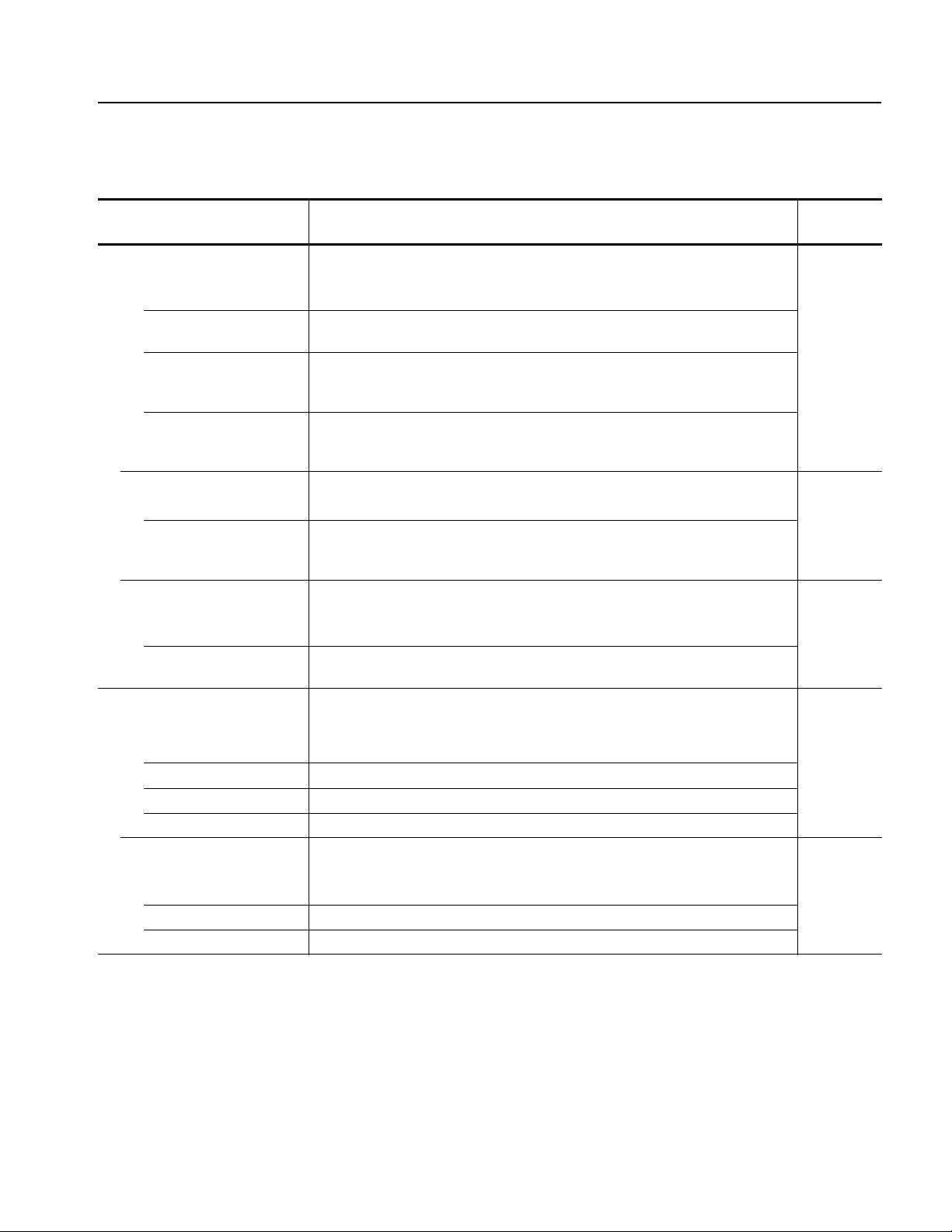
Table 1-9: Output characteristics (cont.)
Specifications
Characteristics Description
PV reference
page
✔Spurious1 (non harmonic) (at 1 V
amplitude) page 4-32
p-p
AFG3011 10 Hz ≤ frq < 1 MHz: < –60 dBc
1 MHz ≤ frq ≤ 10 MHz: < –50 dBc
AFG3021B, AFG3022B 10 Hz ≤ frq < 1 MHz: < –60 dBc
1 MHz ≤ frq ≤ 25 MHz: < –50 dBc
AFG3101, AFG3102 10 Hz ≤ frq < 1 MHz: < –60 dBc
1 MHz ≤ frq < 25 MHz: < –50 dBc
25 MHz ≤ frq ≤ 100 MHz: –50 dBc + 6 dBc/oct
AFG3251, AFG3252 10 Hz ≤ frq < 1 MHz: < –50 dBc
1 MHz ≤ frq < 25 MHz: < –47 dBc
25 MHz ≤ frq ≤ 240 MHz: –47 dBc + 6 dBc/oct
Phase noise, typical (at 1 V
amplitude)
p-p
AFG3011 10 MHz: < –110 dBc/Hz at 10 kHz offset
AFG3021B, AFG3022B,
20 MHz: < –110 dBc/Hz at 10 kHz offset
AFG3101, AFG3102,
AFG3101, AFG3102
Residual clock noise, typical
AFG3021B, AFG3022B,
–63 dBm
AFG3011
AFG3101, AFG3102,
–57 dBm
AFG3251, AFG3252
Square wave page 4-35
✔Rise time/fall time
AFG3011 ≤ 50 ns
AFG3021B, AFG3022B ≤ 18 ns
AFG3101, AFG3102 ≤ 5ns
AFG3251, AFG3252 ≤ 2.5 ns
Jitter (rms), typical
AFG3021B, AFG3022B,
500 ps
AFG3011
AFG3101, AFG3102 200 ps
AFG3251, AFG3252 100 ps
AFG3000 Series Arbitrary/Function Generators Service Manual 1-7
Page 30

Specifications
Table 1-9: Output characteristics (cont.)
Characteristics Description
Pulse
Pulse width
AFG3011 80 ns to 999.99 s
AFG3021B, AFG3022B 30 ns to 999.99 s
AFG3101, AFG3102 8 ns to 999.99 s
AFG3251, AFG3252 4 ns to 999.99 s
Resolution 10 ps or 5 digits
Pulse duty 0.001% to 99.999%
Leading edge/trailing edge
transition time
AFG3011 50 ns to 0.625 * pulse period
AFG3021B, AFG3022B 18 ns to 0.625 * pulse period
AFG3101, AFG3102 5 ns to 0.625 * pulse period
AFG3251, AFG3252 2.5 ns to 0.625 * pulse period
Resolution 10 ps or 4 digits
Overshoot, typical < 5%
Jitter (rms), typical
AFG3021B, AFG3022B,
AFG3011
AFG3101, AFG3102 200 ps
AFG3251, AFG3252 100 ps
Ramp
Linearity (at frequency: 1 kHz, amplitude: 1 V
AFG3251, AFG3252,
AFG3011
AFG3021B, AFG3022B ≤ 0.1% of peak output at 10% to 90% of amplitude range
AFG3101, AFG3102 ≤ 0.15% of peak output at 10% to 90% of amplitude range
Symmetry 0% to 100%
Arbitrary
Rise time/fall time, typical
AFG3011 ≤ 80 ns
AFG3021B, AFG3022B ≤ 20 ns
AFG3101, AFG3102 ≤ 8ns
AFG3251, AFG3252 ≤ 3ns
500 ps
, symmetry: 100%)
p-p
≤ 0.2% of peak output at 10% to 90% of amplitude range
PV reference
page
1-8 AFG3000 Series Arbitrary/Function Generators Service Manual
Page 31

Table 1-9: Output characteristics (cont.)
Specifications
Characteristics Description
Jitter (rms), typical
AFG3021B, AFG3022B
4 ns
AFG3011
AFG3101, AFG3102 1 ns at 1 GS/s
4 ns at 250 MS/s
AFG3251, AFG3252 500 ps at 2 GS/s
4 ns at 250 MS/s
1. Exclude harmonics and channel crosstalk.
Table 1-10: Modulation
Characteristics Description
AM (Amplitude Modulation)
Carrier waveforms Standard waveforms (except Pulse, DC, and Noise) and Arb
Modulation source Internal or External
Internal modulating
Sine, Square, Ramp, Noise, and Arb
waveforms
Internal modulating
2 mHz to 50.00 kHz
frequency
Depth
0.0% to 120.0%
FM (Frequency Modulation)
Carrier waveforms Standard waveforms (except Pulse, DC, and Noise) and Arb
Modulation source Internal or External
Internal modulating
Sine, Square, Ramp, Noise, and Arb
waveforms
Internal modulating
2 mHz to 50.00 kHz
frequency
Peak deviation
AFG3011 DC to 5 MHz
AFG3021B, AFG3022B DC to 12.5 MHz
AFG3101, AFG3102 DC to 50 MHz
AFG3251, AFG3252 DC to 120 MHz
1
2
PV reference
page
AFG3000 Series Arbitrary/Function Generators Service Manual 1-9
Page 32

Specifications
Table 1-10: Modulation (cont.)
Characteristics Description
PM (Phase Modulation)
Carrier waveforms Standard waveforms (except Pulse, DC, and Noise) and Arb
Modulation source Internal or External
Internal modulating
Sine, Square, Ramp, Noise, and Arb
waveforms
Internal modulating
2 mHz to 50.00 kHz
frequency
Phase deviation range
0.0 to 180.0 degrees
FSK (Frequency Shift Keying)
Carrier waveforms Standard waveforms (except Pulse, DC, and Noise) and Arb
Modulation source Internal or External
Internal key rate 2 mHz to 1.000 MHz
Number of keys 2
PWM (Pulse Width Modulation)
Carrier waveforms Pulse
Modulation source Internal or External
Internal modulating
Sine, Square, Ramp, Noise, and Arb
waveforms
Internal modulating
2 mHz to 50.00 kHz
frequency
Deviation range
0.0% to 50.0% of pulse period
Sweep
Type Linear or Logarithmic
Start/stop frequency
3
AFG3011 1 μHz (except Arb: 1 mHz) to 10 MHz
AFG3021B, AFG3022B 1 μHz (except Arb: 1 mHz) to 25 MHz
AFG3101, AFG3102 1 μHz (except Arb: 1 mHz) to 100 MHz
AFG3251, AFG3252 1 μHz (except Arb: 1 mHz) to 240 MHz
Sweep/hold/return time
4
Range: 1 ms to 300 s (sweep time)
0 ms to 300 s (hold/return time)
Resolution: 1 ms or 4 digits
Total sweep time accuracy,
≤ 0.4%
typical
2
2
1. The maximum waveform length for Arb is 4,096. Waveform data points over 4,096 are ignored.
2. The maximum waveform length for Arb is 2,048. Waveform data points over 2,048 are ignored.
3. Pulse, DC, and Noise waveforms are not available. Start and stop frequencies depend on the waveform shape.
4. Total sweep time = Sweep time + Hold time + Return time ≤ 300 s
1-10 AFG3000 Series Arbitrary/Function Generators Service Manual
Page 33

Inputs/Outputs
Table 1-11: Front panel
Characteristics Description
Trigger output
Level Positive TTL level pulse into 1 kΩ
Impedance 50 Ω
Jitter (rms), typical
AFG3021B, AFG3022B,
AFG3011
AFG3101, AFG3102 200 ps
AFG3251, AFG3252 100 ps
Trigger input
Level TTL compatible
Pulse width 100 ns minimum
Impedance 10 kΩ
Slope Positive/negative, selectable
Trigger delay 0.0 ns to 85.000 s
Jitter (rms), typical Burst: < 500 ps (trigger input to signal output)
500 ps
Resolution: 100 ps or 5 digits
Specifications
AFG3000 Series Arbitrary/Function Generators Service Manual 1-11
Page 34

Specifications
Table 1-12: Rear panel
Characteristics Description
External modulation input
Input range ±1.0 V full scale (except FSK)
3.3 V logic level (FSK)
Impedance 10 kΩ
Frequency range AM, FM, PM, FSK, PWM: DC to 25 kHz (sampling rate: 122 kS/s)
External reference output AFG3011, AFG3101, AFG3102, AFG3251, and AFG3252
Impedance 50 Ω, AC coupled
Amplitude 1.2 V
External reference input
Impedance 1 kΩ, AC coupled
Required input voltage swing 100 mV
Lock range 10 MHz ± 35 kHz
CH1 Additional input AFG3101, AFG3102, AFG3251, and AFG3252
Impedance 50 Ω
Input range –1 V to +1 V (DC + peak AC)
Bandwidth DC to 10 MHz (–3 dB) at 1 V
into 50 Ω
p-p
to 5 V
p-p
p-p
p-p
General
Table 1-13: System characteristics
Characteristics Description
Warm-up time, typical 20 minutes minimum
Power on self calibration, typical < 16 s
Configuration times, typical USB LAN GPIB
Function change 95 ms 103 ms 84 ms
Frequency change 2 ms 19 ms 2 ms
Amplitude change 60 ms 67 ms 52 ms
Select user Arb 88 ms 120 ms 100 ms
Data download, typical 4000 points waveform data
GPIB: 42 ms
USB: 20 ms
LAN: 84 ms
Acoustic noise, typical < 50 dBA
Weight (approximate) 4.5 kg
Dimensions See Figure 1-1 and Figure 1-2 on page 1-14
1-12 AFG3000 Series Arbitrary/Function Generators Service Manual
Page 35

Tabl e 1- 1 4 : Po wer
Characteristics Description
Source voltage and frequency 100 V to 240 V, 47 Hz to 63 Hz
115 V, 360 Hz to 440 Hz
Power consumption Less than 120 W
Table 1-15: Environmental
Characteristics Description
Temperature range
Operating 0 °C to +50 °C
Non operating –30 °C to +70 °C
Humidity
Operating At or below +40 °C: ≤ 80%
> +40 °C to +50 °C: ≤ 60%
Altitude
Operating Up to 3,000 meters (10,000 feet)
Specifications
AFG3000 Series Arbitrary/Function Generators Service Manual 1-13
Page 36

Specifications
6.3
(0.25)
3.1
(0.13)
329.6
(12.98)
156.3
(6.16)
24.0
(0.95)
6.5
(0.26)
All dimensions are shown
in mm and (in).
27.3
(1.08)
39.5
(1.56)
118.5
(4.67)
51.2
(2.02)
67.5
(2.66)
34.6
(1.37)
22
(0.87)
154.4
(6.08)
7.6
(0.30)
5.1
(0.20)
6.0
(0.24)
BNC connectors
28.7
(1.13)
BNC connectors
176.2
(6.94)
101.6
(4.00)
482.6
(19.00)
465.5
(18.32)
37.3
(1.47)
154.3
(6.08)
44.4
(1.75)
101.6
(4.00)
36.8
(1.45)
37.3
(1.47)
25.4
(1.00)
Front
Figure 1-1: AFG3000 Series dimensions
Figure 1-2: RM3100 Rackmount dimensions
1-14 AFG3000 Series Arbitrary/Function Generators Service Manual
Page 37

Operating Information
Page 38

Page 39

Operating Basics
This section provides installation and operating information that is necessary for
service.
General Features
The following table and bulleted list describe the general features of the AFG3000
Series Arbitrary/Function Generators.
Table 2-1: General features
Feature AFG3011 AFG3021B AFG3022B AFG3101 AFG3102 AFG3251 AFG3252
Channel 1 121212
Sine 10 MHz 25 MHz 100 MHz 240 MHz
Pulse / Square 5 MHz 12.5 MHz 50 MHz 120 MHz
Ramp / Gaussian 100 kHz 250 kHz 1 MHz 2.4 MHz
Arbitrary
Waveform Length 2 to 131,072 2 to 131,072 2 to 131,072 2 to 131,072
Sample Rate
Waveform Length ≤ 16384
250 MS/s
250 MS/s
1 GS/s
2 GS/s
16384 < Waveform Length
Resolution 14 bits 14 bits 14 bits 14 bits
Amplitude 20 V
Display Color Mono-
Interface USB, LAN,
250 MS/s
p-p
GPIB
250 MS/s
10 V
p-p
Color Color Color
chrome
USB, LAN, GPIB USB, LAN, GPIB USB, LAN, GPIB
250 MS/s
10 V
p-p
Three functions integrated into one generator
10 MHz to 240 MHz Function Generator
5 MHz to 120 MHz Pulse Generator
14 bits Arbitrary Waveform Generator
Ground isolation
Synchronous operation
USB flash drive interface
250 MS/s
5V
p-p
AFG3000 Series Arbitrary/Function Generators Service Manual 2-1
Page 40

Operating Basics
156.3 mm
(6.16 in)
329.6 mm
(12.98 in)
Installation
Operating Requirements
Environmental
ArbExpress Software
Context-sensitive Help system
Use the following information to safely install your instrument.
AFG
DUAL CHANNEL
3102
ARBITRARY/FUNCTION GENERATOR
USB
USB
Memory
Memory
1GS/s
100MHz
View
Sine
Square
Ramp
Pulse
Arb
Output
Run ModeFunction
Continuous Modulation
Frequency/Period Amplitude/High
Phase Delay
Leading/TrailingDuty/Width
Edit
Utility
Save RecallMore...
Channel
Ch2
Ch1
Sweep Burst
Offset/Low
Help
Default
TriggerTrigger
InputOutput Output
Figure 2-1: Front size
1. Place the instrument on a cart or bench, observing clearance requirements:
Sides: 50 mm (2 in)
Rear: 50 mm (2 in)
2. Before operating, ensure that the ambient temperature is between 0 °C and
+50 °C (+32 °F and +122 °F).
CAUTION. To ensure proper cooling, keep both sides of the instrument clear of
obstructions.
Power Supply Requirements
Source Voltage and Frequency 100 V to 240 V, 47 Hz to 63 Hz
Power Consumption Less than 120 W
or 115 V, 360 Hz to 440 Hz
2-2 AFG3000 Series Arbitrary/Function Generators Service Manual
Page 41

Protect Your Instrument from Misuse
Do not mistake Output connectors for Input.
Output
Input
Adapter (P/N: 013-0345-00)
0.125 A fuse (P/N: 159-0454-00 (3 each))
Check Input and Output
Connectors
Figure 2-2: Output and Input connectors
The instrument has both input and output connectors on the front panel.
When connecting a cable, be sure to distinguish the input connector from the output
connectors.
Operating Basics
Avoid Instrument Damage
The arbitrary/function generator input and output connectors are floating
inputs/outputs.
WAR N I N G. To avoid personal injury due to electric shock, do not apply voltages
in excess of 42 Vpk to any BNC connector ground or to the chassis ground.
CAUTION. Do not short output pins or apply external voltages to Output
connectors. The instrument may be damaged.
Do not apply excessive inputs over +5 V to Trigger Input connector. The instrument
may be damaged.
The instrument will be damaged if a large DC or AC voltage is applied to the output
or input connectors. To protect the output circuits, a fuse adapter is provided as an
optional accessory. When the instrument is used by students or other inexperienced
users, always attach the fuse adapter to the output connectors to avoid damage.
Tektronix part numbers for the fuse adapter are as follows:
Figure 2-3: Fuse adapter
AFG3000 Series Arbitrary/Function Generators Service Manual 2-3
Page 42

Operating Basics
Chassis ground
Common ground
Floating Ground
Since the common (input and output channel common) of the arbitrary/function
generator is electrically isolated from the chassis ground (the instrument chassis
and ground line of the AC connector), you can make a floating connection between
the instrument and other equipment.
All the signal output connectors are connected to the common ground, and the
remote interface connector is connected to the chassis ground.
CAUTION. When you make a floating connection, review the following
precautions:
The maximum rated voltage between the chassis ground and common ground is
42 V
and common ground goes over 42 V
(DC + peak AC). When the potential voltage between the chassis ground
p-p
, the internal protective circuit will be
p-p
activated to protect the circuits. However, higher voltage may cause the internal
circuits in the instrument to be damaged.
When a potential voltage exists between the chassis ground and common ground, a
short circuit from output to ground causes the instrument internal fuse to open and
the output is stopped. If the fuse opens, you need to contact your local Tektronix
Service Support.
When a potential voltage exists between the common ground and chassis ground,
short-circuiting between them may lead to excessive current flow and the internal
or external circuits may be damaged.
Figure 2-4: Grounding equivalent circuit
2-4 AFG3000 Series Arbitrary/Function Generators Service Manual
Page 43
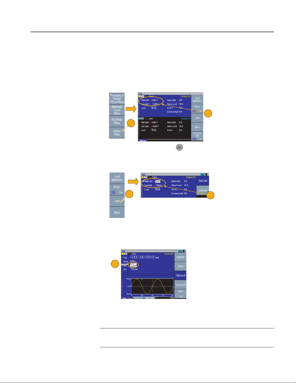
Protect Your DUT
Operating Basics
Use care when you connect the instrument Channel Output to your DUT (device
under test). To avoid damage to your DUT, the following preventive measures are
provided. Follow these steps to set the limit values for high level and low level.
2
1
1. Push the front-panel Top Menu button. The Output Menu is displayed at
the bottom of the bezel menu. Select Output Menu.
2. In this example, High Limit is set to 5.000 V, and Low Limit is set to –5.000 V.
3
3. Push the Limit bezel button.
4. Select High Limit. Use numeric keys or the general purpose knob to enter a
value. Enter 50 mV for High Limit, and -50 mV for Low Limit.
5
5. Push the front-panel Sine button to display the waveform parameter. Confirm
that High and Low voltage levels were changed.
You cannot enter any values greater than 50 mV for High level.
NOTE. When you set limit values using Output Menu, a level indicator is displayed
at left end of graph area. Refer to Screen Interface on page 2-10 for the level
indicator.
4
AFG3000 Series Arbitrary/Function Generators Service Manual 2-5
Page 44

Operating Basics
1. Insert the AC power cord into the power receptacle on the rear panel.
2. Use the front-panel power button to power on the instrument.
Wait until the front panel display shows that all power-on self tests passed. In
this example, High Limit is set to 5.000 V, and Low Limit is set to –5.000 V.
120
VA
1. Use the front-panel power button to power off the instrument.
Powering the Instrument On and Off
Power On
1
DUAL CHANNEL
AFG
3102
ARBITRARY/FUNCTION GENERATOR
USB
USB
Memory
2
Memory
1GS/s
100MHz
View
Sine
Square
Ramp
Pulse
Arb
Output
Run ModeFunction
Continuous Modulation
Frequency/Period Amplitude/High
Phase Delay
Leading/TrailingDuty/Width
Edit
Utility
Save RecallMore...
Channel
Ch2
Ch1
Sweep Burst
Offset/Low
Help
Default
TriggerTrigger
InputOutput Output
NOTE. You can select the instrument settings, Default settings or Last powered-off
settings, which are restored when you power on the instrument. Use the Utility
menu to change the settings.
Power Off
DUAL CHANNEL
AFG
3102
ARBITRARY/FUNCTION GENERATOR
USB
USB
Memory
1
Memory
1GS/s
100MHz
View
Sine
Square
Ramp
Pulse
Arb
Output
Run ModeFunction
Continuous Modulation
Frequency/Period Amplitude/High
Phase Delay
Leading/TrailingDuty/Width
Edit
Utility
Save RecallMore...
Channel
Ch2
Ch1
Sweep Burst
Offset/Low
Help
Default
TriggerTrigger
InputOutput Output
2-6 AFG3000 Series Arbitrary/Function Generators Service Manual
Page 45

Self Test and Self Calibration
1. Push the front-panel Utility button.
2. Push the -more- bezel button.
3. Push the Diagnostics/Calibration bezel button.
4. The Diagnostics/Calibration execution menu is displayed.
To execute self calibration, push the Execute Calibration bezel button.
To execute the instrument diagnostics, push the Execute Diagnostics bezel
button.
The arbitrary/function generator performs a limited set of hardware tests at
power-on. You can also perform the manual diagnostics and/or self calibration
using the Utility menu.
Operating Basics
3
1
2
4
CAUTION. Do not power off the instrument while executing self calibration. The
calibration data may be damaged/ lost.
NOTE. Before executing self calibration, ensure that the ambient temperature is
between +20 °C and +30 °C (+68 °F to +86 °F).
Allow a 20 minute warm-up period prior to executing self calibration.
AFG3000 Series Arbitrary/Function Generators Service Manual 2-7
Page 46

Operating Basics
Numeric keypad
Power On/Off switch
Shortcut buttons
Function buttons
Bezel menu buttons
Trigger Input connector
USB connector
View button
Trigger Output connector
CH1 and CH2 Output connectors
Menu buttons
Top Menu button
Getting Acquainted with Your Instrument
Front Panel Overview
The front panel is divided into easy-to-use functional areas. This section provides
you with a quick overview of the front-panel controls and the screen interface. The
following figure shows the front panel of the dual-channel model.
AFG
DUAL CHANNEL
3102
ARBITRARY/FUNCTION GENERATOR
USB
USB
Memory
Memory
1GS/s
100MHz
Sine
Square
Ramp
Pulse
Arb
Output
View
Run ModeFunction
Continuous Modulation
Frequency/Period Amplitude/High
Offset/Low
Phase Delay
Leading/TrailingDuty/Width
Edit
Utility
Save RecallMore...
Channel
Ch2
Ch1
Sweep Burst
Help
Default
TriggerTrigger
InputOutput Output
Figure 2-5: Front-panel controls
2-8 AFG3000 Series Arbitrary/Function Generators Service Manual
Page 47

Operating Basics
120
VA
Chassis ground
screw
Security slot
Rear Panel
The following illustration shows the rear-panel connectors for the instrument.
Figure 2-6: Rear panel
EXT REF INPUT. This input is used when synchronizing multiple arbitrary/function
generators or an arbitrary/function generator and another device.
EXT REF OUTPUT. When you want to synchronize multiple AFG3000 series
arbitrary/function generators, or synchronize your arbitrary/function generator and
another instrument, use the external reference output connector. (Except
AFG3021B and AFG3022B)
ADD INPUT. The ADD INPUT connector is provided with AFG3101/AFG3102 and
AFG3251/AFG3252. This connector lets you add an external signal to the CH1
output signal.
EXT MODULATION INPUT (CH1 and CH2). The CH1 INPUT and CH2 INPUT
are independent. The signal input level of these connectors controls modulation depth.
USB. Used to connect a USB controller. (Type B)
LAN. Used to connect the instrument to a network. Connect a 10BASE-T or
100BASE-T cable here.
GPIB. Used to control the instrument through GPIB commands.
Security Slot. Use a standard laptop computer security cable to secure your
instrument to your location.
Chassis Ground Screw. The chassis ground screw is used to ground the instrument.
Use a unified coarse screw (#6-32, 6.35 mm length or less).
AFG3000 Series Arbitrary/Function Generators Service Manual 2-9
Page 48

Operating Basics
Bezel menu
Main display area
(Parameter listing
or Graph)
View tab
Message display area
Output status
Level meter
1. Shows maximum amplitude level of your instrument.
2. Shows the range of high limit and low limit set by the user.
3. Shows the amplitude level that is currently selected. Use the
front-panel power button to power off the instrument.
Screen Interface
Figure 2-7: Screen interface
Bezel Menu. When you push a front panel button, the instrument displays the
corresponding menu on the right side of the screen. The menu shows the options
that are available when you push the unlabeled bezel buttons directly to the right of
the screen. (Some documentation may also refer to the bezel buttons as option
buttons, side-menu buttons, or soft keys.)
Main Display Area and View Tab. Pushing the front-panel View button toggles
through the view format of the main display area. The view tabs correspond with
the current view format. The arbitrary/function generator can display three
different screen formats.
Output Status. If the output is set to disable, Output Off message is displayed in this
area. When you push the front panel channel output button to enable the output, the
message will disappear.
Message Display Area. A message that monitors hardware status such as clock or
trigger is displayed in this area.
Level Meter. Amplitude level is displayed. Refer to page 2-5 for setting the high
limit and low limit. The following figure describes the level meter.
1
2-10 AFG3000 Series Arbitrary/Function Generators Service Manual
2
3
Page 49

Theory of Operation
Page 50

Page 51

Theory of Operation
This section describes the electrical operation of the AFG3000 Series
Arbitrary/Function Generators to the module level. It describes the basic operation
of each functional circuit block shown in Figure 3-1. The descriptions for the one
and two channel units, and the color and monochrome units are slightly different.
Overview
AFG3000 Series Arbitrary/Function Generators provide seven models with
different frequency and number of channels. Each model consists of two major
sections: the platform section and the generator section. The platform section is
common to each model.
The combination of circuit boards in each model is shown in Table 3-1.
Table 3-1: Combination of circuit boards used in each model
Circuit board AFG3021B AFG3022B AFG3101 AFG3102 AFG3251 AFG3252 AFG3011
A11 Generator with Amp 1ch 1
A12 Generator with Amp 2ch 1
A31 Generator 1ch 1
A32 Generator 2ch 1
A41 Generator High 1ch 1
A42 Generator High 2ch 1
A43 Generator 1
A51 Output Amp 1 2
A61 Output Amp 1 2
A72 CPU 1111111
A75 Front Panel 1111111
A80 BNC/Peltola 11212
A81 Front BNC Insulator 1111111
A82 Rear BNC Insulator 1111111
AFG3000 Series Arbitrary/Function Generators Service Manual 3-1
Page 52

Theory of Operation
NFRO&
WLX
FUL&
GR0W[(
Q,
+
&
'
$
URWDUHQH*
SLK&
Q
2
G
R0
W
[
(
Q,K&
IH5W[(
Q
,
IH5
W
[
(
WX2
W
S
HF[H
Q,''$
WLXFUL&83&
FWH0$5
025
830
'&/
HP
R
UKFRQR0
\DOSVL'
WLQ8\OSS
X6U
HZR3
DH
U$
G
QXRU*\WHID6
GQ
XRU*JQ
LWDRO
)
%68
%,
3
*
1$
/
WLXFUL&\UDPLU3
9
9
9
9
VURWDOXJH5O
D
F
R
/
9
9
9
%68
\URPH0
72%#
\URPH0
U
RWDUHQH*
SLK&Q2
'$
&$
Q,
URWDORV,
QD)
UHO
O
R
UWQR&
U
HWUHYQ
,
H
WRPH5
HFDIUHWQ,
%,3*
1
$/
#
#
SP
$HU3
SP$HU
3
VURWDOXJH5
ODFR/
99
$)*[
H[FHSW$)*[
DQG$)*
$0%+PUWNCVQT
$0%+PUWNCVQT
7ULJJHU
,QSXW
&LUFXLW
&DOLEUDWLRQ
&LUFXLW
#(TQPV
2CPGN$QCTF
&DOLEUDWLRQ
&LUFXLW
$$
)LOWHU2XWSXW
$PSOLILHU
'&2IIVHW
$$
)LOWHU2XWSXW
$PSOLILHU
'&2IIVHW
7ULJ2XWSXW
&LUFXLW
7ULJJHU
2XW
&+
2XWSXW
([W7ULJ
,Q
&+
2XWSXW
)GPGTCVQT%*%*
###
)GPGTCVQT%*
####
)DQ
Figure 3-1: AFG3000 Series block diagram
3-2 AFG3000 Series Arbitrary/Function Generators Service Manual
Page 53

Platform
Theory of Operation
CPU Board (A72)
Front Panel
CPU Circuit: The CPU Circuit contains an MPU, Flash RAM, and DRAM to
control the instrument. The liquid crystal controller and the USB circuit are
included in the MPU.
Local Regulators: This regulator stabilizes and supplies +3.3 V and +5.0 V for the
logic circuit.
Remote Interface: The A72 board contains a GPIB and LAN driver circuit.
Fan Controller: This circuit controls the speed of the fan.
Primary Circuit: Contains the power switch and the filter circuit.
Signal I/O Circuit: The Reference Clock Input/Output and the Modulation Input
signals are transmitted to the Generator section through this board.
The Front Panel controls a rubber button matrix, LED, a buzzer, and a rotary
encoder.
Power Supply
LCD
Fan
BNC Insulator Board
(A81/ A82)
The power supply module provides +4.3 V, ±15 V, and +5 V to the circuit. This
power supply module accepts the input voltage within the range of 250 VAC from
90 VAC.
The display is a color/monochrome Quarter VGA (320 x 240) STN LCD display.
The high voltage power for LCD is supplied through the inverter. A monochrome
display is used in the AFG3021B.
A 90 mm by 90 mm size, DC 12 V type fan. It is driven by fan controller on the
CPU board.
These boards insulate the I/O signal from the chassis. The A81 board is used for
the rear-panel connectors and the A82 board is used for the front-panel connectors.
AFG3000 Series Arbitrary/Function Generators Service Manual 3-3
Page 54

Theory of Operation
Generator Section
Generator with Amp Board
(A11/A12/A43)
Isolator: Transmit the serial control signal from the CPU board to the following
circuits with electrical insulation.
Clock Circuit: Generates a 1 GHz high-speed clock necessary for the signal
generation from a 10 MHz reference clock by PLL. This circuit has a function of
selecting the reference signal source as well.
GoC ASIC: GoC (Generator on Chip) ASIC is a CMOS waveform synthesis IC
which includes 2 GS/s DA, Direct Digital Synthesis, waveform SRAM 128 K, x8
MUX, Modulation, Burst and Sweep. So GoC manages most of the generator
section.
Tri g g er C ircu i t : Receives an External Trigger input signal, executes the level
conversion, then supplies the level converted trigger signal to the GoC ASIC.
Pre-Amplifier Circuit: Converts the differential output signal of the GoC to single
ended output, then supplies the single ended output to the Output Amplifier
through the Attenuator.
Output Amplifier: The output of the pre-amplifier is amplified and output. LPF is
used when a sine wave is output.
Trig Out Circuit: Sync Out signal from GoC ASIC is level converted to Trigger Out.
ADC: Modulation by an external source is performed by digitally sampling the
external input from the Ext Modulation Input connector.
Local Regulator: Supplies the necessary +1.8 V, +3.3 V, +15 V, and
On/Off Relay: On/Off of the output signal.
Calibration Circuit: DC Calibration of the output signal is done by a 16 bit AD
Converter.
Generator with Amp Board
(A31/A32/A41/A42)
3-4 AFG3000 Series Arbitrary/Function Generators Service Manual
The A31/A32/A41/A42 boards are the same as the A11/A12 boards except they
have a different Output Amplifier board.
–15 V power.
Page 55

Theory of Operation
Output Amp Board
(A51/A61)
Output Amplifier: Amplifying the output of the pre-amplifier with the DC offset.
Output Filter: LPF is used when a sine wave is output.
AFG3000 Series Arbitrary/Function Generators Service Manual 3-5
Page 56

Theory of Operation
3-6 AFG3000 Series Arbitrary/Function Generators Service Manual
Page 57

Performance Verification
Page 58

Page 59

Performance Verification
Two types of Performance Verification procedures can be performed on this
product: Self Tests and Performance Tests. You may not need to perform all of
these procedures, depending on what you want to accomplish.
To quickly confirm that the AFG3000 Series Arbitrary/Function Generators
are operating properly, complete the Self Tests which begin on page 4-1.
Advantage: These procedures require minimal time to perform, and test the
internal hardware of the AFG3000 Series Arbitrary/Function Generators.
To further check functionality and proper calibration, first complete the Self
Tests; then complete the Performance Tests beginning on page 4-3.
Advantages: These procedures add direct checking of warranted
specifications. These procedures require suitable test equipment and more time
to execute. (Refer to Table 4-2, “Test equipment,” on page 4)
Self Tests
There are two types of tests in this section that provide a quick way to confirm basic
functionality and proper adjustment:
Diagnostics
Diagnostics
Calibration (you must perform this calibration before the performance tests.)
These procedures use internal diagnostics to verify that the instrument passes the
internal circuit tests, and calibration routines to check and adjust the instrument
internal calibration constants.
This procedure uses internal routines to verify that the instrument is operating
correctly.
Equipment required None
Prerequisites
Power on the instrument and allow a 20 minute warm-up before
doing this procedure.
The instrument must be operating at an ambient temperature
between +0 °C and +50 °C.
AFG3000 Series Arbitrary/Function Generators Service Manual 4-1
Page 60

Performance Verification
Do the following steps to run the internal routines that confirm basic functionality
and proper adjustment:
1. Select Diagnostics in the Utility menu:
Utility (front-panel) > -more- (bezel) > Diagnostics/Calibration >
Execute Diagnostics
2. Wait until the test is completed.
3. Verify passing of the diagnostics.
If the diagnostics completes without finding any problems, the message
“PASSED” is displayed.
When an error is detected during diagnostic execution, the instrument displays
an error code. Error codes are described in Error codes on page 6-30.
4. Press any front-panel button to exit the diagnostics.
Calibration
This procedure uses internal routines to verify that the instrument is operating
correctly.
Equipment required None
Prerequisites
Power on the instrument and allow a 20 minute warm-up before
doing this procedure.
An ambient temperature is between +20 °C and +30 °C.
Do the following steps to run the internal routines that confirm basic functionality
and proper adjustment:
1. Select Diagnostics in the Utility menu;
Utility (front-panel) > -more- (bezel) > Diagnostics/Calibration >
Execute Calibration
2. Wait until the test is completed.
3. Verify passing of the calibration.
If the calibration completes without any problems, the message “PASSED” is
displayed.
When an error is detected during calibration execution, the instrument displays
an error code. Error codes are described in Error Codes on page 6-30.
4. Press any front-panel button to exit the diagnostics.
4-2 AFG3000 Series Arbitrary/Function Generators Service Manual
Page 61

Performance Tests
Table 4-1: Performance test items
Performance Verification
NOTE. Do not turn off the power while executing calibration. If the power is turned
off during calibration, data stored in internal nonvolatile memory may be lost.
The Performance Tests include functional tests, such as the interface functional
test, in this manual.
The Functional Tests verify the functions; they verify that the AFG3000 Series
Arbitrary/Function Generators features operate. They do not verify that they
operate within limits.
The Performance Tests verify that the AFG3000 Series Arbitrary/Function
Generators performs as warranted. The Performance Tests check all the
characteristics that are designated as checked in Specifications. (The
characteristics that are checked appear with a 4 in Specifications.)
Titles Test items Reference page
Frequency/Period Test Internal clock output frequency accuracy page 4-20
Amplitude Test Amplitude accuracy page 4-21
DC Offset Test Amplitude accuracy page 4-23
AC Flatness Test AC Flatness page 4-26
Harmonic Distortion Test Harmonic Distortion page 4-28
THD (Total Harmonic Distortion) Test Total Harmonic Distortion page 4-30
Spurious Test Spurious page 4-32
Rise-Fall Time Test Rise-Fall Time page 4-35
Performance Conditions
The tests in this section comprise an extensive, valid confirmation of performance
and functionality when the following requirements are met:
The cabinet covers must be on the AFG3000 Series.
The instrument must have been performed and passed the procedures under
calibration and diagnostics.
The instrument must have been calibrated/adjusted at an ambient temperature
between +20 °C and +30 °C.
The instrument must be operating at an ambient temperature between +0 °C
and +50 °C.
The instrument must have had a warm-up period of at least 20 minutes.
AFG3000 Series Arbitrary/Function Generators Service Manual 4-3
Page 62

Performance Verification
Equipment Required
Table 4-2 lists the required equipment used to complete the performance tests.
Table 4-2: Test equipment
Description Minimum requirements Recommended equipment Purpose
1. Digital Multi Meter (DMM) AC volts, true rms, AC coupled
Accuracy:
DC volts
Accuracy: 50 ppm, resolution 100μV
Resistance
Accuracy:
2. Power Meter 100 kHz to 250 MHz
1 μW to 100 mW (–30 dBm to +20 dBm)
Accuracy: 0.02 dB
Resolution: 0.01 dB
3. Power Head 100 kHz to 250 MHz
1 μW to 100 mW (–30 dBm to +20 dBm)
4. Frequency Counter Accuracy: 0.01ppm
Phase measurement
5. Oscilloscope 1 GHz Bandwidth
50 Ω input termination
6. Spectrum Analyzer 20 kHz to 1.25 GHz Tektronix RSA3303A Checks output signals.
7. BNC Coaxial Cable 50 Ω, male to male BNC connector,
91 cm
8. BNC terminator 50 Ω,
9. Attenuator 50 Ω, x10, BNC Tektronix part number
10. Adapter Dual-Banana
Plug
11. Adapter BNC(fe)-N(ma) BNC (female) to N (male) Tektronix part number
BNC (female) to dual banana Tektronix part number
± 0.1% to 1 kHz
± 0.05 Ω
±1Ω, 2W, DC to 1GHz, BNC Tektronix part number
Agilent 3458A Measures voltage. Used in
multiple procedures.
R&S NRVS Measures voltage. Used in
multiple procedures.
R&S NRV-Z5 Measures voltage. Used in
multiple procedures.
Agilent 53132A Checks clock frequency.
Tektronix TDS5104B Checks output signals. Used in
multiple procedures.
Harmonics Spurious.
Tektronix part number
012-0482-00
011-0049-02
011-0059-03
103-0090-00
103-0045-00
Signal interconnection
Signal termination
Signal attenuation
Signal interconnection to a
DMM
Signal interconnection to a
Spectrum Analyzer
4-4 AFG3000 Series Arbitrary/Function Generators Service Manual
Page 63

Performance Verification
Test Record
Photocopy this test record and use to record the performance test results for your
AFG3000 Series Arbitrary/Function Generators. Excel spreadsheet Test record
with embedded calculation formulas is also available in standard accessory
document CD P/N 063-3828-xx.
AFG3000 Series Performance
Instrument Serial Number: Certificate Number:
Temperature: RH %:
Date of Calibration: Technician:
Test Record
AFG3000 Series Performance Test Record
Minimum
Frequency
Sine at 1.000000 MHz 0.999999 MHz 1.000001 MHz
Pulse at 1.000000 MHz 0.999999 MHz 1.000001 MHz
Amplitude
Test result Maximum
AFG3011 CF = 2 / (1 + 50 Ω / Measurement Ω) =
CH1Amplitude
30.0 mVrms at 1.00 kHz (30.0 × CF – 1.307) mVrms (30.0 × CF + 1.307) mVrms
300.0 mVrms at 1.00 kHz (300.0 × CF – 6.71) mVrms (300.0× CF + 6.71) mVrms
800.0 mVrms at 1.00 kHz (800.0 × CF – 16.71) mVrms (800.0 × CF + 16.71) mVrms
1.500 Vrms at 1.00 kHz (1.500 × CF – 0.0307) Vrms (1.500 × CF + 0.0307) Vrms
2.000 Vrms at 1.00 kHz (2.000 × CF – 0.0407) Vrms (2.000 × CF + 0.0407) Vrms
2.500 Vrms at 1.00 kHz (2.500 × CF – 0.0507) Vrms (2.500 × CF + 0.0507) Vrms
3.500 Vrms at 1.00 kHz (3.500 × CF – 0.0707 Vrms (3.500 × CF + 0.0707) Vrms
AFG3000 Series Arbitrary/Function Generators Service Manual 4-5
Page 64

Performance Verification
AFG3000 Series Performance Test Record
Minimum
Amplitude
AFG302xB, AFG310x CF = 2 / (1 + 50 Ω / Measurement Ω) =
CH1Amplitude
30.0 mVrms at 1.00 kHz (30.0 × CF – 0.654) mVrms (30.0 × CF + 0.654) mVrms
300.0 mVrms at 1.00 kHz (300.0 × CF – 3.35) mVrms (300.0× CF + 3.35) mVrms
800.0 mVrms at 1.00 kHz (800.0 × CF – 8.35) mVrms (800.0 × CF + 8.35) mVrms
1.500 Vrms at 1.00 kHz (1.500 × CF – 0.0154) Vrms (1.500 × CF + 0.0154) Vrms
2.000 Vrms at 1.00 kHz (2.000 × CF – 0.0204) Vrms (2.000 × CF + 0.0204) Vrms
2.500 Vrms at 1.00 kHz (2.500 × CF – 0.0254) Vrms (2.500 × CF + 0.0254) Vrms
3.500 Vrms at 1.00 kHz (3.500 × CF – 0.0354) Vrms (3.500 × CF + 0.0354) Vrms
CH2 Amplitude
30.0 mVrms at 1.00 kHz (30.0 × CF – 0.654) mVrms (30.0 × CF + 0.654) mVrms
300.0 mVrms at 1.00 kHz (300.0 × CF – 3.35) mVrms (300.0× CF + 3.35) mVrms
800.0 mVrms at 1.00 kHz (800.0 × CF – 8.35) mVrms (800.0 × CF + 8.35) mVrms
1.500 Vrms at 1.00 kHz (1.500 × CF – 0.0154) Vrms (1.500 × CF + 0.0154) Vrms
Test result Maximum
2.000 Vrms at 1.00 kHz (2.000 × CF – 0.0204) Vrms (2.000 × CF + 0.0204) Vrms
2.500 Vrms at 1.00 kHz (2.500 × CF – 0.0254) Vrms (2.500 × CF + 0.0254) Vrms
3.500 Vrms at 1.00 kHz (3.500 × CF – 0.0354) Vrms (3.500 × CF + 0.0354) Vrms
AFG325x CF = 2 / (1 + 50 Ω / Measurement Ω) =
CH1 Amplitude
0.030 Vrms at 1.00 kHz (30.0 × CF – 0.654) mVrms (30.0 × CF + 0.654) mVrms
0.300 Vrms at 1.00 kHz (300.0 × CF – 3.35) mVrms (300.0× CF + 3.35) mVrms
0.800 Vrms at 1.00 kHz (800.0 × CF – 8.35) mVrms (800.0 × CF + 8.35) mVrms
1.500 Vrms at 1.00 kHz (1.500 × CF – 0.0154) Vrms (1.500 × CF + 0.0154) Vrms
CH2 Amplitude
30.0 mVrms at 1.00 kHz (30.0 × CF – 0.654) mVrms (30.0 × CF + 0.654) mVrms
300.0 mVrms at 1.00 kHz (300.0 × CF – 3.35) mVrms (300.0× CF + 3.35) mVrms
800.0 mVrms at 1.00 kHz (800.0 × CF – 8.35) mVrms (800.0 × CF + 8.35) mVrms
1.500 Vrms at 1.00 kHz (1.500 × CF – 0.0154) Vrms (1.500 × CF + 0.0154) Vrms
4-6 AFG3000 Series Arbitrary/Function Generators Service Manual
Page 65

AFG3000 Series Performance Test Record
Performance Verification
Minimum
DC Offset
AFG3011 CF = 2 / (1 + 50 Ω / Measurement Ω) =
CH1 DC Offset
+5.000 Vdc (+5.000 × CF – 0.110) Vdc (+5.000 × CF + 0.110 Vdc
0.000 Vdc –0.010 Vdc +0.010 Vdc
–5.000 Vdc (–5.000 × CF – 0.110) Vdc (–5.000 × CF + 0.110) Vdc
AFG302xB, AFG310x CF = 2 / (1 + 50 Ω / Measurement Ω) =
CH1 DC Offset
+5.000 Vdc (+5.000 × CF – 0.055) Vdc (+5.000 × CF + 0.055 Vdc
0.000 Vdc –0.005 Vdc +0.005 Vdc
–5.000 Vdc (–5.000 × CF – 0.055) Vdc (-5.000 × CF + 0.055) Vdc
CH2 DC Offset
+5.000 Vdc (+5.000 × CF – 0.055) Vdc (+5.000 × CF + 0.055) Vdc
0.000 Vdc –0.005 Vdc +0.005 Vdc
–5.000 Vdc (–5.000 × CF – 0.055) Vdc (–5.000 × CF + 0.055) Vdc
Test result Maximum
AFG325x CF = 2 / (1 + 50 Ω / Measurement Ω) =
CH1 DC Offset
+2.500 Vdc (+2.500 × CF – 0.030) Vdc (+2.500 × CF + 0.030 Vdc
0.000 Vdc –0.005 Vdc +0.005 Vdc
–2.500 Vdc (–2.500 × CF – 0.030) Vdc (–2.500 × CF + 0.030) Vdc
CH2 DC Offset
+2.500 Vdc (+2.500 × CF – 0.030) Vdc (+2.500 × CF + 0.030) Vdc
0.000 Vdc –0.005 Vdc +0.005 Vdc
–2.500 Vdc (–2.500 × CF – 0.030) Vdc (–2.500 × CF + 0.030) Vdc
AFG3000 Series Arbitrary/Function Generators Service Manual 4-7
Page 66

Performance Verification
AFG3000 Series Performance Test Record
Minimum
AC Flatness
AFG3011
CH1 AC Flatness
Frequency 100.00 kHz
(Ampl: +4.0 dBm)
Frequency 500.00 kHz Reference – 0.15 dB dB Reference + 0.15 dB
Frequency 1.00 MHz Reference – 0.15 dB dB Reference + 0.15 dB
Frequency 5.00 MHz Reference – 0.30 dB dB Reference + 0.30 dB
Frequency 10.00 MHz Reference – 0.30 dB dB Reference + 0.30 dB
AFG302xB
CH1 AC Flatness
Frequency 100.00 kHz
(Ampl: +4.0 dBm)
Frequency 500.00 kHz Reference – 0.15 dB dB Reference + 0.15 dB
Frequency 1.00 MHz Reference – 0.15 dB dB Reference + 0.15 dB
Frequency 5.00 MHz Reference – 0.30 dB dB Reference + 0.30 dB
---------- dB ( = Reference) ----------
---------- dB ( = Reference) ----------
Test result Maximum
Frequency 15.00 MHz Reference – 0.30 dB dB Reference + 0.30 dB
Frequency 25.00 MHz Reference – 0.50 dB dB Reference + 0.50 dB
CH2 AC Flatness
Frequency 100.00 kHz
(Ampl: +4.0 dBm)
Frequency 500.00 kHz Reference – 0.15 dB dB Reference + 0.15 dB
Frequency 1.00 MHz Reference – 0.15 dB dB Reference + 0.15 dB
Frequency 5.00 MHz Reference – 0.30 dB dB Reference + 0.30 dB
Frequency 15.00 MHz Reference – 0.30 dB dB Reference + 0.30 dB
Frequency 25.00 MHz Reference – 0.50 dB dB Reference + 0.50 dB
---------- dB ( = Reference) ----------
4-8 AFG3000 Series Arbitrary/Function Generators Service Manual
Page 67

AFG3000 Series Performance Test Record
Performance Verification
Minimum
AC Flatness
AFG310x
CH1 AC Flatness
Frequency 100.00 kHz
(Ampl: +4.0 dBm)
Frequency 1.00 MHz Reference – 0.15 dB dB Reference + 0.15 dB
Frequency 5.00 MHz Reference – 0.30 dB dB Reference + 0.30 dB
Frequency 25.00 MHz Reference – 0.50 dB dB Reference + 0.50 dB
Frequency 50.00 MHz Reference – 0.50 dB dB Reference + 0.50 dB
Frequency 100.0 MHz Reference – 0.50 dB dB Reference + 0.50 dB
CH2 AC Flatness
Frequency 100.00 kHz
(Ampl: +4.0 dBm)
Frequency 1.00 MHz Reference – 0.15 dB dB Reference + 0.15 dB
Frequency 5.00 MHz Reference – 0.30 dB dB Reference + 0.30 dB
Frequency 25.00 MHz Reference – 0.50 dB dB Reference + 0.50 dB
---------- dB( = Reference) ----------
---------- dB( = Reference) ----------
Test result Maximum
Frequency 50.00 MHz Reference – 0.50 dB dB Reference + 0.50 dB
Frequency 100.0 MHz Reference – 0.50 dB dB Reference + 0.50 dB
AFG325x
CH1 AC Flatness
Frequency 100.00 kHz
(Ampl: +4.0 dBm)
Frequency 1.00 MHz Reference – 0.15 dB dB Reference + 0.15 dB
Frequency 5.00 MHz Reference – 0.30 dB dB Reference + 0.30 dB
Frequency 25.00 MHz Reference – 0.50 dB dB Reference + 0.50 dB
Frequency 50.00 MHz Reference – 0.50 dB dB Reference + 0.50 dB
Frequency 100.0 MHz Reference – 1.00 dB dB Reference + 1.00 dB
Frequency 150.00 MHz Reference – 1.00 dB dB Reference + 1.00 dB
Frequency 240.0 MHz Reference – 2.00 dB dB Reference + 2.00 dB
---------- dB( = Reference) ----------
AFG3000 Series Arbitrary/Function Generators Service Manual 4-9
Page 68

Performance Verification
AFG3000 Series Performance Test Record
Minimum
AC Flatness
CH2 AC Flatness
Frequency 100.00 kHz
(Ampl: +4.0 dBm)
Frequency 1.00 MHz Reference – 0.15 dB dB Reference + 0.15 dB
Frequency 5.00 MHz Reference – 0.30 dB dB Reference + 0.30 dB
Frequency 25.00 MHz Reference – 0.50 dB dB Reference + 0.50 dB
Frequency 50.00 MHz Reference – 0.50 dB dB Reference + 0.50 dB
Frequency 100.0 MHz Reference – 1.00 dB dB Reference + 1.00 dB
Frequency 150.00 MHz Reference – 1.00 dB dB Reference + 1.00 dB
Frequency 250.0 MHz Reference – 2.00 dB dB Reference + 2.00 dB
---------- dB( = Reference) ----------
Test result Maximum
4-10 AFG3000 Series Arbitrary/Function Generators Service Manual
Page 69

AFG3000 Series Performance Test Record
Performance Verification
Harmonic Distortion Fundamental
= reference
AFG3011 Spectrum Analyzer reading
Sine 20 kHz 20 kHz 40 kHz 60 kHz 80 kHz 100 kHz
CH1 Harmonic Distortion dBc dBc dBc dBc dBc
reading – reference 0 dBc dBc dBc dBc dBc Nth – reference < –55 dBc
Sine 100 kHz 100 kHz 200 kHz 300 kHz 400 kHz 500 kHz
CH1 Harmonic Distortion dBc dBc dBc dBc dBc
reading – reference 0 dBc dBc dBc dBc dBc Nth – reference < –55 dBc
Sine 1 MHz 1 MHz 2 MHz 3 MHz 4 MHz 5 MHz
CH1 Harmonic Distortion dBc dBc dBc dBc dBc
reading – reference 0 dBc dBc dBc dBc dBc Nth – reference < –45 dBc
Sine 10 MHz 10 MHz 20 MHz 35 MHz 40 MHz 50 MHz
CH1 Harmonic Distortion dBc dBc dBc dBc dBc
reading – reference 0 dBc dBc dBc dBc dBc Nth – reference < –45 dBc
AFG302xB Spectrum Analyzer reading
Sine 20 kHz 20 kHz 40 kHz 60 kHz 80 kHz 100 kHz
2nd 3rd 4th 5th Limit
CH1 Harmonic Distortion dBc dBc dBc dBc dBc
reading – reference 0 dBc dBc dBc dBc dBc Nth – reference < –60 dBc
CH2 Harmonic Distortion dBc dBc dBc dBc dBc
reading – reference 0 dBc dBc dBc dBc dBc Nth – reference < –60 dBc
Sine 100 kHz 100 kHz 200 kHz 300 kHz 400 kHz 500 kHz
CH1 Harmonic Distortion dBc dBc dBc dBc dBc
reading – reference 0 dBc dBc dBc dBc dBc Nth – reference < –60 dBc
CH2 Harmonic Distortion dBc dBc dBc dBc dBc
reading – reference 0 dBc dBc dBc dBc dBc Nth – reference < –60 dBc
Sine 1 MHz 1 MHz 2 MHz 3 MHz 4 MHz 5 MHz
CH1 Harmonic Distortion dBc dBc dBc dBc dBc
reading – reference 0 dBc dBc dBc dBc dBc Nth – reference < –50 dBc
CH2 Harmonic Distortion dBc dBc dBc dBc dBc
reading – reference 0 dBc dBc dBc dBc dBc Nth – reference < –50 dBc
AFG3000 Series Arbitrary/Function Generators Service Manual 4-11
Page 70

Performance Verification
AFG3000 Series Performance Test Record
Harmonic Distortion Fundamental
= reference
Sine 25MHz 25 MHz 50 MHz 75 MHz 100 MHz 125 MHz
CH1 Harmonic Distortion dBc dBc dBc dBc dBc
reading – reference 0 dBc dBc dBc dBc dBc Nth – reference < –40 dBc
CH2 Harmonic Distortion dBc dBc dBc dBc dBc
reading – reference 0 dBc dBc dBc dBc dBc Nth – reference < –40 dBc
AFG310x Spectrum Analyzer reading
Sine 1 MHz 1 MHz 2 MHz 3 MHz 4 MHz 5 MHz
CH1 Harmonic Distortion dBc dBc dBc dBc dBc
reading – reference 0 dBc dBc dBc dBc dBc Nth – reference < –50 dBc
CH2 Harmonic Distortion dBc dBc dBc dBc dBc
reading – reference 0 dBc dBc dBc dBc dBc Nth – reference < –50 dBc
Sine 5 MHz 5 MHz 10 MHz 15 MHz 20 MHz 25 MHz
CH1 Harmonic Distortion dBc dBc dBc dBc dBc
reading – reference 0 dBc dBc dBc dBc dBc Nth – reference < –37 dBc
CH2 Harmonic Distortion dBc dBc dBc dBc dBc
2nd 3rd 4th 5th Limit
reading – reference 0 dBc dBc dBc dBc dBc Nth – reference < –37 dBc
Sine 25MHz 25 MHz 50 MHz 75 MHz 100 MHz 125 MHz
CH1 Harmonic Distortion dBc dBc dBc dBc dBc
reading – reference 0 dBc dBc dBc dBc dBc Nth – reference < –37 dBc
CH2 Harmonic Distortion dBc dBc dBc dBc dBc
reading – reference 0 dBc dBc dBc dBc dBc Nth – reference < –37 dBc
Sine 100 MHz 100 MHz 200 MHz 300 MHz 400 MHz 500 MHz
CH1 Harmonic Distortion dBc dBc dBc dBc dBc
reading – reference 0 dBc dBc dBc dBc dBc Nth – reference < –37 dBc
CH2 Harmonic Distortion dBc dBc dBc dBc dBc
reading – reference 0 dBc dBc dBc dBc dBc Nth – reference < –37 dBc
4-12 AFG3000 Series Arbitrary/Function Generators Service Manual
Page 71

AFG3000 Series Performance Test Record
Performance Verification
Harmonic Distortion Fundamental
= reference
AFG325x Spectrum Analyzer reading
Sine 1 MHz 1 MHz 2 MHz 3 MHz 4 MHz 5 MHz
CH1 Harmonic Distortion dBc dBc dBc dBc dBc
reading – reference 0 dBc dBc dBc dBc dBc Nth – reference < –50 dBc
CH2 Harmonic Distortion dBc dBc dBc dBc dBc
reading – reference 0 dBc dBc dBc dBc dBc Nth – reference < –50 dBc
Sine 5 MHz 5 MHz 10 MHz 15 MHz 20 MHz 25 MHz
CH1 Harmonic Distortion dBc dBc dBc dBc dBc
reading – reference 0 dBc dBc dBc dBc dBc Nth – reference < –37 dBc
CH2 Harmonic Distortion dBc dBc dBc dBc dBc
reading – reference 0 dBc dBc dBc dBc dBc Nth – reference < –37 dBc
Sine 100 MHz 100 MHz 200 MHz 300 MHz 400 MHz 500 MHz
CH1 Harmonic Distortion dBc dBc dBc dBc dBc
reading – reference 0 dBc dBc dBc dBc dBc Nth – reference < –30 dBc
CH2 Harmonic Distortion dBc dBc dBc dBc dBc
2nd 3rd 4th 5th Limit
reading – reference 0 dBc dBc dBc dBc dBc Nth – reference < –30 dBc
Sine 240 MHz 240 MHz 480 MHz 720 MHz 960 MHz 1.20 GHz
CH1 Harmonic Distortion dBc dBc dBc dBc dBc
reading – reference 0 dBc dBc dBc dBc dBc Nth – reference < –30 dBc
CH2 Harmonic Distortion dBc dBc dBc dBc dBc
reading – reference 0 dBc dBc dBc dBc dBc Nth – reference < –30 dBc
AFG3000 Series Arbitrary/Function Generators Service Manual 4-13
Page 72

Performance Verification
THD
C
n
2
n2=
∑
C
1
-----------------------=
THD
C
n
2
n2=
∑
C
1
-----------------------=
AFG3000 Series Performance Test Record
Total Harmonic Distortion (THD)
AFG3xxxx Spectrum Analyzer reading
Fundamental
2nd 3rd 4th 5th 6th 7th
= reference
Sine 20.0 kHz 20 kHz 40 kHz 60 kHz 80 kHz 100 kHz 120 kHz 140 kHz
CH1 reading (dBm) A
reading - reference (A
– A1) (dBc) B1= 0 B2=B
n
= 10
n
Bn/20
C
= A2=A
1
C1= 1 C2=C
=A
3
=B
3
=C
3
=A
4
=B
4
=C
4
=A
5
=B
5
=C
5
=A
6
=B
6
=C
6
=
7
=
7
=
7
Limit
< 0.2%
CH2 reading (dBm) A1= A2= A3= A4= A5= A6= A7=
reading - reference (An – A1) (dBc) B1= 0 B2= B3= B4= B5= B6= B7=
= 10
n
Bn/20
C1= 1 C2= C3= C4= C5= C6= C7=
C
Limit
< 0.2%
4-14 AFG3000 Series Arbitrary/Function Generators Service Manual
Page 73

AFG3000 Series Performance Test Record
Spurious
AFG3011 Spectrum Analyzer Measurement
Performance Verification
Frequency Center
Frequency
CH1 Spurious
Sine 100 kHz 10 MHz /
300 MHz
Sine 1.00 MHz 10 MHz /
300 MHz
Sine 10.00 MHz 10 MHz /
300 MHz
AFG302xB Spectrum Analyzer Measurement
Frequency Center
Frequency
CH1 Spurious
Sine 100 kHz 10 MHz /
300 MHz
Sine 1.00 MHz 10 MHz /
300 MHz
Sine 10.00 MHz 10 MHz /
300 MHz
Span RBW Spurious Frequency Spurious (Max) Limit
20 MHz /
600 MHz
20 MHz /
600 MHz
20 MHz /
600 MHz
Span RBW Spurious Frequency Spurious (Max) Limit
20 MHz /
600 MHz
20 MHz /
600 MHz
20 MHz /
600 MHz
20 kHz /
20 kHz
20 kHz /
20 kHz
20 kHz /
20 kHz
20 kHz /
20 kHz
20 kHz /
20 kHz
20 kHz /
20 kHz
MHz
MHz
MHz
MHz
MHz
MHz
MHz
MHz
MHz
MHz
MHz
MHz
dBc
dBc
dBc
dBc
dBc
dBc
dBc
dBc
dBc
dBc
dBc
dBc
< –60 dBc
< –50 dBc
< –50 dBc
< –60 dBc
< –50 dBc
< –50 dBc
Sine 25.00 MHz 10 MHz /
300 MHz
CH2 Spurious
Sine 100 kHz 10 MHz /
300 MHz
Sine 1.00 MHz 10 MHz /
300 MHz
Sine 10.00 MHz 10 MHz /
300 MHz
Sine 25.00 MHz 10 MHz /
300 MHz
20 MHz /
600 MHz
20 MHz /
600 MHz
20 MHz /
600 MHz
20 MHz /
600 MHz
20 MHz /
600 MHz
20 kHz /
20 kHz
20 kHz /
20 kHz
20 kHz /
20 kHz
20 kHz /
20 kHz
20 kHz /
20 kHz
MHz
MHz
MHz
MHz
MHz
MHz
MHz
MHz
MHz
MHz
dBc
dBc
dBc
dBc
dBc
dBc
dBc
dBc
dBc
dBc
< –50 dBc
< –60 dBc
< –50 dBc
< –50 dBc
< –50 dBc
AFG3000 Series Arbitrary/Function Generators Service Manual 4-15
Page 74

Performance Verification
AFG3000 Series Performance Test Record
Spurious
AFG310x Spectrum Analyzer Measurement
Frequency Center
Frequency
CH1 Spurious
Sine 100 kHz 10 MHz
300 MHz
Sine 1.00 MHz 10 MHz
300 MHz
Sine 10.00 MHz 10 MHz
300 MHz
Sine 25.00 MHz 10 MHz
300 MHz
Sine 50.00 MHz 10 MHz
300 MHz
Sine 100.00 MHz 10 MHz
300 MHz
CH2 Spurious
Sine 100 kHz 10 MHz
300 MHz
Sine 1.00 MHz 10 MHz
300 MHz
Span RBW Spurious Frequency Spurious (Max) Limit
20 MHz
600 MHz
20 MHz
600 MHz
20 MHz
600 MHz
20 MHz
600 MHz
20 MHz
600 MHz
20 MHz
600 MHz
20 MHz
600 MHz
20 MHz
600 MHz
20 kHz
20 kHz
20 kHz
20 kHz
20 kHz
20 kHz
20 kHz
20 kHz
20 kHz
20 kHz
20 kHz
20 kHz
20 kHz
20 kHz
20 kHz
20 kHz
MHz
MHz
MHz
MHz
MHz
MHz
MHz
MHz
MHz
MHz
MHz
MHz
MHz
MHz
MHz
MHz
dBc
dBc
dBc
dBc
dBc
dBc
dBc
dBc
dBc
dBc
dBc
dBc
dBc
dBc
dBc
dBc
< –60 dBc
< –50 dBc
< –50 dBc
< –50 dBc
< –44 dBc
< –38 dBc
< –60 dBc
< –50 dBc
Sine 10.00 MHz 10 MHz
300 MHz
Sine 25.00 MHz 10 MHz
300 MHz
Sine 50.00 MHz 10 MHz
300 MHz
Sine 100.00 MHz 10 MHz
300 MHz
20 MHz
600 MHz
20 MHz
600 MHz
20 MHz
600 MHz
20 MHz
600 MHz
20 kHz
20 kHz
20 kHz
20 kHz
20 kHz
20 kHz
20 kHz
20 kHz
MHz
MHz
MHz
MHz
MHz
MHz
MHz
MHz
dBc
dBc
dBc
dBc
dBc
dBc
dBc
dBc
< –50 dBc
< –50 dBc
< –44 dBc
< –38 dBc
4-16 AFG3000 Series Arbitrary/Function Generators Service Manual
Page 75

AFG3000 Series Performance Test Record
Spurious
AFG325x Spectrum Analyzer Measurement
Performance Verification
Frequency Center
Frequency
CH1 Spurious
Sine 100 kHz 10 MHz
300 MHz
Sine 1.00 MHz 10 MHz
300 MHz
Sine 10.00 MHz 10 MHz
300 MHz
Sine 25.00 MHz 10 MHz
300 MHz
Sine 50.00 MHz 10 MHz
300 MHz
Sine 100.00 MHz 10 MHz
300 MHz
Sine 200.00 MHz 10 MHz
300 MHz
Sine 240.00 MHz 10 MHz
300 MHz
CH2 Spurious
Span RBW Spurious Frequency Spurious (Max) Limit
20 MHz
600 MHz
20 MHz
600 MHz
20 MHz
600 MHz
20 MHz
600 MHz
20 MHz
600 MHz
20 MHz
600 MHz
20 MHz
600 MHz
20 MHz
600 MHz
20 kHz
20 kHz
20 kHz
20 kHz
20 kHz
20 kHz
20 kHz
20 kHz
20 kHz
20 kHz
20 kHz
20 kHz
20 kHz
20 kHz
20 kHz
20 kHz
MHz
MHz
MHz
MHz
MHz
MHz
MHz
MHz
MHz
MHz
MHz
MHz
MHz
MHz
MHz
MHz
dBc
dBc
dBc
dBc
dBc
dBc
dBc
dBc
dBc
dBc
dBc
dBc
dBc
dBc
dBc
dBc
< –50 dBc
< –47 dBc
< –47 dBc
< –47 dBc
< –41 dBc
< –35 dBc
< –29 dBc
< –28 dBc
Sine 100 kHz 10 MHz
300 MHz
Sine 1.00 MHz 10 MHz
300 MHz
Sine 10.00 MHz 10 MHz
300 MHz
Sine 25.00 MHz 10 MHz
300 MHz
Sine 50.00 MHz 10 MHz
300 MHz
Sine 100.00 MHz 10 MHz
300 MHz
Sine 200.00 MHz 10 MHz
300 MHz
Sine 240.00 MHz 10 MHz
300 MHz
20 MHz
600 MHz
20 MHz
600 MHz
20 MHz
600 MHz
20 MHz
600 MHz
20 MHz
600 MHz
20 MHz
600 MHz
20 MHz
600 MHz
20 MHz
600 MHz
20 kHz
20 kHz
20 kHz
20 kHz
20 kHz
20 kHz
20 kHz
20 kHz
20 kHz
20 kHz
20 kHz
20 kHz
20 kHz
20 kHz
20 kHz
20 kHz
MHz
MHz
MHz
MHz
MHz
MHz
MHz
MHz
MHz
MHz
MHz
MHz
MHz
MHz
MHz
MHz
dBc
dBc
dBc
dBc
dBc
dBc
dBc
dBc
dBc
dBc
dBc
dBc
dBc
dBc
dBc
dBc
< –50 dBc
< –47 dBc
< –47 dBc
< –47 dBc
< –41 dBc
< –35 dBc
< –29 dBc
< –28 dBc
AFG3000 Series Arbitrary/Function Generators Service Manual 4-17
Page 76

Performance Verification
AFG3000 Series
Performance Test Record
Minimum Test result Maximum
Rise-Fall Time
AFG3011
CH1 Rise Time Amplitude: 1.0 V
Fall Time Amplitude: 1.0 V
Rise Time Amplitude: 10.0 V
Fall Time Amplitude: 10.0 V
pp
pp
pp
pp
- - - - - 50 ns
- - - - - 50 ns
- - - - - 50 ns
- - - - - 50 ns
AFG302xB
CH1 Rise Time Amplitude: 1.0 V
Fall Time Amplitude: 1.0 V
Rise Time Amplitude: 10.0 V
Fall Time Amplitude: 10.0 V
CH2 Rise Time Amplitude: 1.0 V
Fall Time Amplitude: 1.0 V
Rise Time Amplitude: 10.0 V
Fall Time Amplitude: 10.0 V
pp
pp
pp
pp
pp
pp
pp
pp
- - - - - 18 ns
- - - - - 18 ns
- - - - - 18 ns
- - - - - 18 ns
- - - - - 18 ns
- - - - - 18 ns
- - - - - 18 ns
- - - - - 18 ns
AFG310x
CH1 Rise Time Amplitude: 1.0 V
Fall Time Amplitude: 1.0 V
Rise Time Amplitude: 10.0 V
Fall Time Amplitude: 10.0 V
CH2 Rise Time Amplitude: 1.0 V
Fall Time Amplitude: 1.0 V
Rise Time Amplitude: 10.0 V
Fall Time Amplitude: 10.0 V
pp
pp
pp
pp
pp
pp
pp
pp
- - - - - 5 ns
- - - - - 5 ns
- - - - - 5 ns
- - - - - 5 ns
- - - - - 5 ns
- - - - - 5 ns
- - - - - 5 ns
- - - - - 5 ns
4-18 AFG3000 Series Arbitrary/Function Generators Service Manual
Page 77

AFG3000 Series Performance Test Record
Minimum Test result Maximum
Rise-Fall Time
AFG325x
Performance Verification
CH1 Rise Time Amplitude: 1.0 V
Fall Time Amplitude: 1.0 V
Rise Time Amplitude: 5.0 V
Fall Time Amplitude: 5.0 V
CH2 Rise Time Amplitude: 1.0 V
Fall Time Amplitude: 1.0 V
Rise Time Amplitude: 5.0 V
Fall Time Amplitude: 5.0 V
pp
pp
pp
pp
pp
pp
pp
pp
- - - - - 2.5 ns
- - - - - 2.5 ns
- - - - - 2.5 ns
- - - - - 2.5 ns
- - - - - 2.5 ns
- - - - - 2.5 ns
- - - - - 2.5 ns
- - - - - 2.5 ns
AFG3000 Series Arbitrary/Function Generators Service Manual 4-19
Page 78

Performance Verification
Frequency counter
50 Ω BNC coaxial cable
CH1 Output
AFG3000 Series
Inputs
Frequency/Period Test
This test verifies the frequency accuracy of the arbitrary/function generator. All
output frequencies are derived from a single generated frequency. Only one
frequency point of channel 1 is required to be checked.
1. Connect the arbitrary/function generator to the frequency counter as shown in
Figure 4-1.
Figure 4-1: Frequency/Period tests
2. Push the Default front-panel button and OK menu button to recall the
arbitrary/function generator default setup.
3. Set up the arbitrary/function generator using the following steps:
Select menu Setting Operation
Function Sine Sine (front)
Frequency 1.000000 MHz Frequency/Period (front)
Amplitude 1.00 Vpp Amplitude/High (front)
Channel 1 Output On On (front)
4. Check that reading of the Frequency Counter is between 0.999999 MHz and
1.000001 MHz.
5. Set up the arbitrary/function generator using the following steps:
Select menu Setting Operation
Function Pulse Pulse (front)
6. Check that reading of the frequency counter is between 0.999999 MHz and
1.000001 MHz.
4-20 AFG3000 Series Arbitrary/Function Generators Service Manual
Page 79
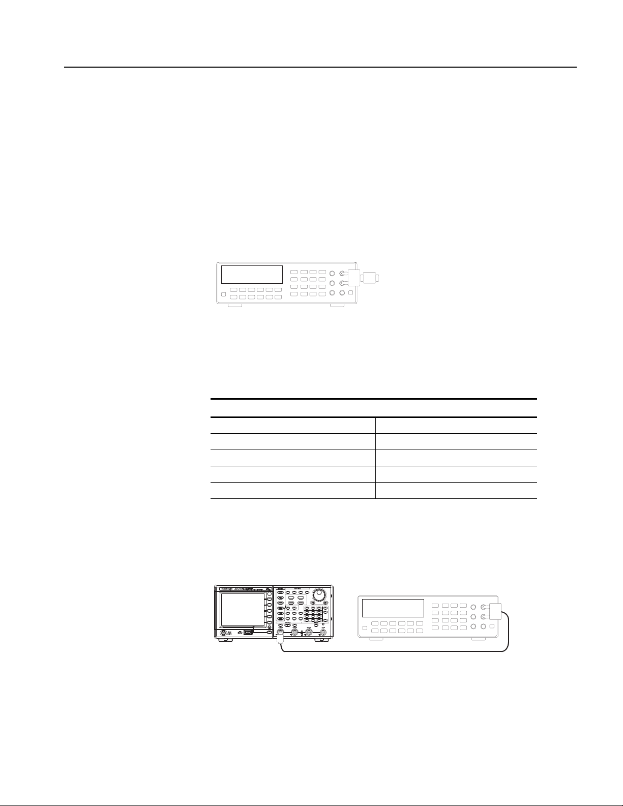
Amplitude Test
DMM
BNC-Dual banana adapter + 50 Ω terminator
DMM
50 Ω BNC coaxial cable + 50 Ω terminator
CH1 Output
AFG3000 series
BNC-Dual banana
adapter
Performance Verification
This test verifies the amplitude accuracy of the arbitrary/function generator. All
output amplitudes are derived from a combination of attenuators and 3 dB variable
gain. Some amplitude points are checked. This test uses a 50 Ω terminator. It is
necessary to know the accuracy of the 50 Ω terminator in advance of this amplitude
test. This accuracy is used as a calibration factor.
1. Connect the 50 Ω terminator to the DMM as shown in Figure 4-2 and measure
the register value.
Figure 4-2: 50 Ω terminator accuracy
2. Calculate the 50 Ω calibration factor (CF) from the reading value and record
as follows:
CF (Calibration Factor) = 2 / (1 + 50 Ω / Measurement Ω)
Measurement (reading of the DMM) CF
Ω
Examples
50.50 Ω 1.0050 (= 2 / (1 + 50 / 50.50))
49.62 Ω 0.9962 (= 2 / (1 + 50 / 49.62))
3. Connect the arbitrary/function generator to the DMM as shown in Figure 4-3.
Be sure to connect the 50 Ω terminator to the arbitrary/function generator
Output connector side.
Figure 4-3: Amplitude tests
AFG3000 Series Arbitrary/Function Generators Service Manual 4-21
Page 80

Performance Verification
4. Set up the arbitrary/function generator using the following steps:
Select menu Setting Operation
Function Sine Sine (front)
Frequency 1.000000 kHz Frequency/Period (front)
Amplitude Units V rms
The voltage unit should be
matched to that of DMM.
Amplitude 0.030 Vrms Amplitude/High (front)
Channel 1 Output On On (front)
Top Menu > Amplitude/Level Menu > -more> Units > V rms
5. Verify that each amplitude measurement is within the range specified in the
following tables.
AFG3011 Measurement Range
Function Frequency Amplitude
Sine 1.000 kHz 30.0 mVrms mVrms (30.0 × CF ± 1.307) mVrms
Sine 1.000 kHz 300.0 mVrms mVrms (300.0 × CF ± 6.71) mVrms
Sine 1.000 kHz 800.0 mVrms mVrms (800.0 × CF ± 16.71) mVrms
Sine 1.000 kHz 1.500 Vrms Vrms (1.500 × CF ± 0.0307) Vrms
Sine 1.000 kHz 2.000 Vrms Vrms (2.000 × CF ± 0.0407) Vrms
Sine 1.000 kHz 2.500 Vrms Vrms (2.500 × CF ± 0.0507) Vrms
Sine 1.000 kHz 3.500 Vrms Vrms (3.500 × CF ± 0.0707) Vrms
AFG302xB and AFG310x Measurement Range
Function Frequency Amplitude
Sine 1.000 kHz 30.0 mVrms mVrms (30.0 × CF ± 0.654) mVrms
Sine 1.000 kHz 300.0 mVrms mVrms (300.0 × CF ± 3.35) mVrms
Sine 1.000 kHz 800.0 mVrms mVrms (800.0 × CF ± 8.35) mVrms
Sine 1.000 kHz 1.500 Vrms Vrms (1.500 × CF ± 0.0154) Vrms
Sine 1.000 kHz 2.000 Vrms Vrms (2.000 × CF ± 0.0204) Vrms
Sine 1.000 kHz 2.500 Vrms Vrms (2.500 × CF ± 0.0254) Vrms
Sine 1.000 kHz 3.500 Vrms Vrms (3.500 × CF ± 0.0354) Vrms
4-22 AFG3000 Series Arbitrary/Function Generators Service Manual
Page 81

DC Offset Test
DMM
BNC-Dual banana adapter + 50 Ω terminator
Performance Verification
AFG325x Measurement Range
Function Frequency Amplitude
Sine 1.000 kHz 30.0 mVrms mVrms (30.0 × CF ± 0.654) mVrms
Sine 1.000 kHz 300.0 mVrms mVrms (300.0 × CF ± 3.35) mVrms
Sine 1.000 kHz 800.0 mVrms mVrms (800.0 × CF ± 8.35) mVrms
Sine 1.000 kHz 1.500 Vrms Vrms (1.500 × CF ± 0.0154) Vrms
6. (AFG3xx2 only) Repeat steps 3 through 5 for the channel 2 output.
This test verifies the DC offset accuracy of the arbitrary/function generator. This
test uses a 50 Ω terminator. It is necessary to know the accuracy of a 50 Ω
terminator in advance of this test. This accuracy is used for as a calibration factor.
1. Connect the 50 Ω terminator to the DMM as shown in Figure 4-4 and measure
the register value.
Figure 4-4: 50 Ω terminator accuracy
2. Calculate the 50 Ω calibration factor (CF) from the reading value and record
as follows:
CF (Calibration Factor) = 2 / (1 + 50 Ω / Measurement Ω)
Measurement (reading of the DMM) CF
Ω
Examples
50.50 Ω 1.0050 (= 2 / (1 + 50 / 50.50))
49.62 Ω 0.9962 (= 2 / (1 + 50 / 49.62))
AFG3000 Series Arbitrary/Function Generators Service Manual 4-23
Page 82

Performance Verification
DMM
50 Ω BNC coaxial cable + 50 Ω terminator
CH1 Output
AFG3000 series
BNC-Dual banana
adapter
3. Connect the arbitrary/function generator to the DMM as shown in Figure 4-5.
Be sure to connect the 50 Ω terminator to the arbitrary/function generator
Output connector side.
Figure 4-5: DC offset tests
4. Set up the arbitrary/function generator using the following steps:
Select menu Setting Operation
Function DC More... (front) > More Waveform Menu > DC
Offset + 5.000 V
+ 2.500 V (AFG325x)
Channel 1 Output On On (front)
Offset/Low (front)
5. Verify that each offset measurement is within the range specified in the
following tables.
AFG3011 Measurement Range
Function Offset
DC + 5.000 Vdc Vdc (5.000 × CF ± 0.110) Vdc
DC 0.000 Vdc Vdc ± 0.010 Vdc
DC – 5.000 Vdc Vdc (– 5.000 × CF ± 0.110) Vdc
4-24 AFG3000 Series Arbitrary/Function Generators Service Manual
Page 83

Performance Verification
AFG302xB and AFG310x Measurement Range
Function Offset
DC + 5.000 Vdc Vdc (5.000 × CF ± 0.055) Vdc
DC 0.000 Vdc Vdc ± 0.005 Vdc
DC – 5.000 Vdc Vdc (– 5.000 × CF ± 0.055) Vdc
AFG3251 and AFG3252 Measurement Range
Function Offset
DC + 2.500 Vdc Vdc (2.500 × CF ± 0.030) Vdc
DC 0.000 Vdc Vdc ± 0.005 Vdc
DC – 2.500 Vdc Vdc (– 2.500 × CF ± 0.030) Vdc
6. (AFG3xx2 only) Repeat steps 3 through 5 for the channel 2 output.
AFG3000 Series Arbitrary/Function Generators Service Manual 4-25
Page 84

Performance Verification
Power met er
50 Ω BNC coaxial cable
CH1 Output
AFG3000 series
Power head
AC Flatness Test
This test verifies the flatness of a sine wave to 100 kHz sine wave.
1. Connect the arbitrary/function generator to the power meter with a power head
as shown in Figure 4-6.
Figure 4-6: AC flatness tests
2. Set up the arbitrary/function generator using the following steps:
Select menu Setting Operation
Function Sine Sine (front)
Frequency 100.0000 kHz Frequency/Period (front)
Amplitude Units dBm TopMenu > Amplitude/Level Menu > -more- >
Units > dBm
Amplitude + 4.0 dBm Amplitude/High (front)
Channel 1 Output On On (front)
3. Set the frequency of the Power Meter to 100 kHz.
4. Write the Power Meter reading of the 100 kHz sine wave as a reference power
value.
5. Verify that the power measurement at each frequency is within the error
specified in the following tables.
AFG3011 Measurement Range
Function Amplitude Frequency (dB) (dB)
Sine + 4.0 dBm 100.00 kHz = Reference - - - - - -
Sine + 4.0 dBm 500.00 kHz Reference ± 0.15
Sine + 4.0 dBm 1.00 MHz Reference ± 0.15
Sine + 4.0 dBm 5.00 MHz Reference ± 0.30
Sine + 4.0 dBm 10.00 MHz Reference ± 0.30
4-26 AFG3000 Series Arbitrary/Function Generators Service Manual
Page 85

Performance Verification
AFG302xB Measurement Range
Function Amplitude Frequency (dB) (dB)
Sine + 4.0 dBm 100.00 kHz = Reference - - - - - -
Sine + 4.0 dBm 500.00 kHz Reference ± 0.15
Sine + 4.0 dBm 1.00 MHz Reference ± 0.15
Sine + 4.0 dBm 5.00 MHz Reference ± 0.30
Sine + 4.0 dBm 15.00 MHz Reference ± 0.30
Sine + 4.0 dBm 25.00 MHz Reference ± 0.50
AFG310x Measurement Range
Function Amplitude Frequency (dB) (dB)
Sine + 4.0 dBm 100.00 kHz = Reference - - - - - -
Sine + 4.0 dBm 1.00 MHz Reference ± 0.15
Sine + 4.0 dBm 5.00 MHz Reference ± 0.30
Sine + 4.0 dBm 25.00 MHz Reference ± 0.50
Sine + 4.0 dBm 50.00 MHz Reference ± 0.50
Sine + 4.0 dBm 100.00 MHz Reference ± 0.50
AFG325x Measurement Range
Function Amplitude Frequency (dB) (dB)
Sine + 4.0 dBm 100.00 kHz = Reference - - - - - -
Sine + 4.0 dBm 1.00 MHz Reference ± 0.15
Sine + 4.0 dBm 5.00 MHz Reference ± 0.30
Sine + 4.0 dBm 25.00 MHz Reference ± 0.50
Sine + 4.0 dBm 50.00 MHz Reference ± 0.50
Sine + 4.0 dBm 100.00 MHz Reference ± 1.00
Sine + 4.0 dBm 150.00 MHz Reference ± 1.00
Sine + 4.0 dBm 240.00 MHz Reference ± 2.00
6. (AFG3xx2 only) Repeat steps 3 through 5 for the channel 2 output.
AFG3000 Series Arbitrary/Function Generators Service Manual 4-27
Page 86

Performance Verification
Spectrum analyzer (WCA280A)
50 Ω BNC coaxial cable
CH1 Output
AFG3000 series
BNC(Fe)-N(Ma) adapter
Harmonics Distortion Test
This test verifies the harmonic distortion using a spectrum analyzer.
1. Connect the arbitrary/function generator to the spectrum analyzer as shown in
Figure 4-7.
Figure 4-7: Harmonic distortion tests
2. Push the Default front-panel button and OK menu button to recall the
arbitrary/function generator default setup.
3. Set up the arbitrary/function generator using the following steps:
Select menu Setting Operation
Function Sine Sine (front)
Frequency 20.00 kHz: AFG3011/AFG302xB
1.000 MHz: AFG310x
1.000 MHz: AFG325x
Amplitude Units Vpp TopMenu > Amplitude/Level Menu >
Amplitude 1.00 Vpp Amplitude/High (front)
Channel 1 Output On On (front)
Frequency/Period (front)
-more- > Units > Vpp
4. Set up the spectrum analyzer according the frequency setup of the
arbitrary/function generator.
5. Set the Ref Level of the spectrum analyzer to 8 dBm.
6. Read the signal level in the Fundamental frequency for each signal. Use this
level as a Reference value in step 4.
7. Verify that the differences between the reference level and the signal level in
the frequency of higher-order at each frequency are below the limit specified
in the following tables.
4-28 AFG3000 Series Arbitrary/Function Generators Service Manual
Page 87

Performance Verification
8. (AFG3xx2 only) Repeat steps 2 through 7 for the channel 2 output.
AFG3011 Spectrum Analyzer Measurement Limit
Frequency Center
Frequency
20.00 kHz 100 kHz 200 kHz 500 Hz 20 kHz 40 kHz 60 kHz 80 kHz 100 kHz < –55 dBc
100.00 kHz 500 kHz 1 MHz 2 kHz 100 kHz 200 kHz 300 kHz 400 kHz 500 kHz < –55 dBc
1.00 MHz 5.00 MHz 10 MHz 20 kHz 1 MHz 2 MHz 3 MHz 4 MHz 5 MHz < –45 dBc
10.00 MHz 10 MHz/
50 MHz
AFG302xB Spectrum Analyzer Measurement Limit
Frequency Center
Frequency
20.00 kHz 100 kHz 200 kHz 500 Hz 20 kHz 40 kHz 60 kHz 80 kHz 100 kHz < –60 dBc
100.00 kHz 500 kHz 1 MHz 2 kHz 100 kHz 200 kHz 300 kHz 400 kHz 500 kHz < –60 dBc
1.00 MHz 5.00 MHz 10 MHz 20 kHz 1 MHz 2 MHz 3 MHz 4 MHz 5 MHz < –50 dBc
25.00 MHz 125 MHz 250 MHz 20 kHz 25 MHz 50 MHz 75 MHz 100 MHz 125 MHz < –40 dBc
AFG310x Spectrum Analyzer Measurement Limit
Span RBW Fundamental
(= Reference)
20 MHz/
100 MHz
Span RBW Fundamental
20 kHz/
20 kHz
10 MHz 20 MHz 30 MHz 40 MHz 50 MHz < –45dBc
(= Reference)
2nd 3rd 4th 5th Nth - Reference
2nd 3rd 4th 5th Nth - Reference
Frequency Center
Frequency
1 MHz 5.00 MHz 10 MHz 20 kHz 1 MHz 2 MHz 3 MHz 4 MHz 5 MHz < –50 dBc
5 MHz 10 MHz /
25 MHz
25 MHz 125 MHz 250 MHz 20 kHz 25 MHz 50 MHz 75 MHz 100 MHz 125 MHz < –37 dBc
100 MHz 500 MHz 1 GHz 100 kHz 100 MHz 200 MHz 300 MHz 400 MHz 500 MHz < –37 dBc
AFG325x Spectrum Analyzer Measurement Limit
Frequency Center
Frequency
1 MHz 5.00 MHz 10 MHz 20 kHz 1 MHz 2 MHz 3 MHz 4 MHz 5 MHz < –50 dBc
5 MHz 10 MHz /
25 MHz
100 MHz 500 MHz 1 GHz 100 kHz 100 MHz 200 MHz 300 MHz 400 MHz 500 MHz < –30 dBc
240 MHz 625 MHz 1.25 GHz 100 kHz 240 MHz 480 MHz 720 MHz 960 MHz 1.20 GHz < –30 dBc
Span RBW Fundamental
(= Reference)
20 MHz /
50 MHz
Span RBW Fundamental
20 MHz /
50 MHz
20 kHz /
20 kHz
20 kHz /
20 kHz
5 MHz 10 MHz 15 MHz 20 MHz 25 MHz < –37 dBc
(= Reference)
5 MHz 10 MHz 15 MHz 20 MHz 25 MHz < –37 dBc
2nd 3rd 4th 5th Nth - Reference
2nd 3rd 4th 5th Nth - Reference
AFG3000 Series Arbitrary/Function Generators Service Manual 4-29
Page 88

Performance Verification
Spectrum analyzer (WCA280A)
50 Ω BNC coaxial cable
CH1 Output
AFG3000 series
BNC(Fe)-N(Ma) adapter
THD
C
n
2
n2=
∑
C
1
-----------------------=
Total Harmonic Distortion Test
This test verifies the total harmonic distortion (THD) using a spectrum analyzer.
1. Connect the arbitrary/function generator to the spectrum analyzer as shown in
Figure 4-8.
Figure 4-8: Total Harmonic distortion tests
2. Set up the arbitrary/function generator using the following steps:
Select menu Setting Operation
Function Sine Sine (front)
Frequency 20.00 kHz Frequency/Period (front)
Amplitude Units Vpp TopMenu > Amplitude/Level Menu > -more- >
Units > Vpp
Amplitude 1.00 Vpp Amplitude/High (front)
Channel 1 Output On On (front)
3. Set up the spectrum analyzer according to the following table:
Center Frequency Span RBW
100 kHz 200 kHz 500 Hz
4. Set the Ref Level of the spectrum analyzer to 8 dBm.
5. When the THD cannot be measured directly, it is obtained by using the
following calculation:
4-30 AFG3000 Series Arbitrary/Function Generators Service Manual
Page 89
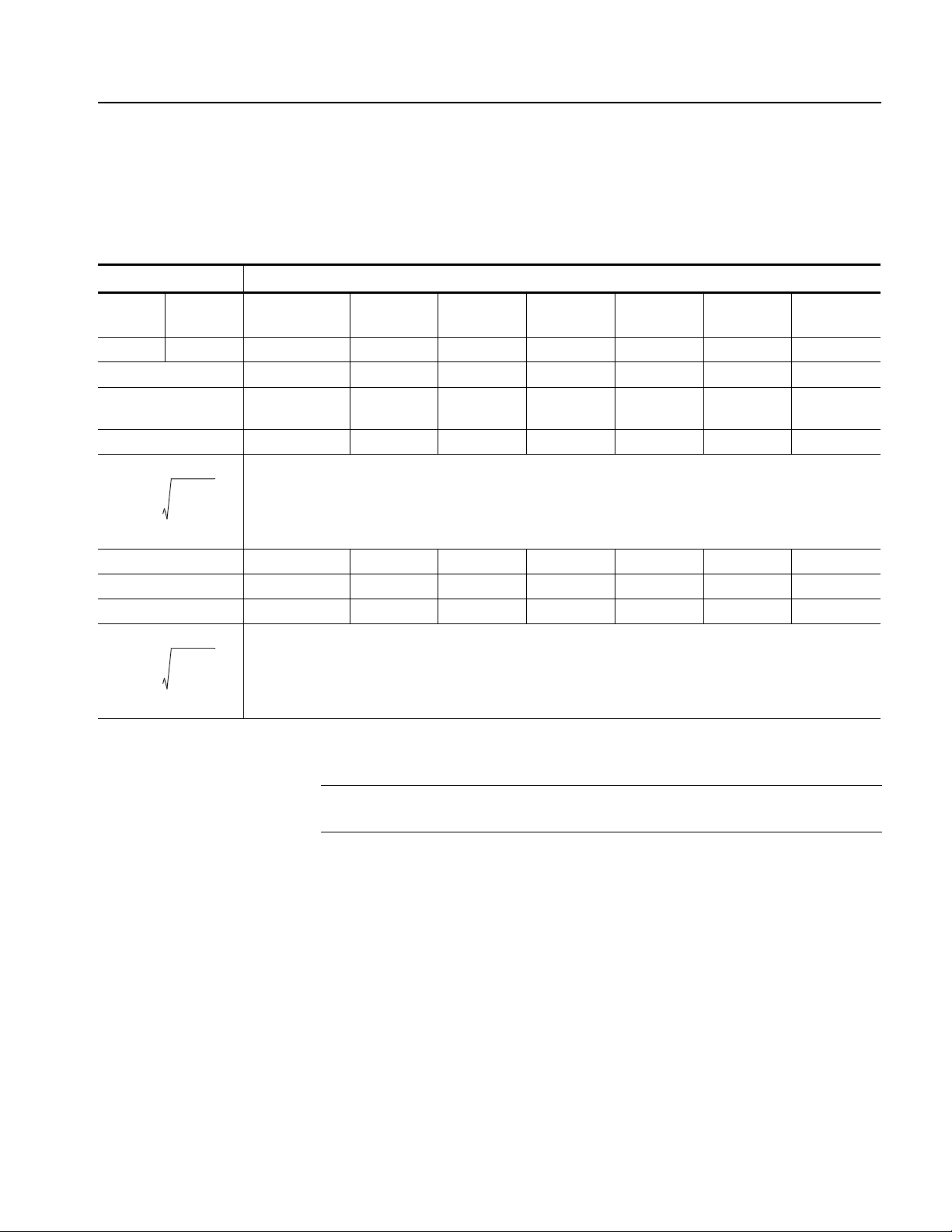
Performance Verification
THD
C
n
2
n2=
∑
C
1
-----------------------=
THD
C
n
2
n2=
∑
C
1
-----------------------=
6. Measure and record each level (A
to A7) to the seventh harmonics of the
1
20 kHz sine wave.
7. Calculate the each B
AFG3xxx Measurement
Function Frequency Fundamental
= reference
sine 20.00 kHz 20 kHz 40 kHz 60 kHz 80 kHz 100 kHz 120 kHz 140 kHz
reading (dBm) A
reading – reference
B
= An – A1 (dBc)
n
C
= 10
n
Bn/20
= A2 =A
1
= 0 B2 =B
B
1
C1 = 1 C2 =C
THD =
Sample: reading 1.5 dBm –58.5 dBm –58.5 dBm –63.5 dBm –58.5 dBm –63.5 dBm –63.5 dBm
reading – reference 0 –60 dBm –60 dBm –65 dBm –60 dBm –65 dBm –65 dBm
C
= 1.000 0.001 0.001 0.000562 0.001 0.000562 0.000562
n
2nd 3rd 4th 5th 6th 7th
to B7, C1 to C7 value and the THD.
1
= A4 =A
3
=B
3
=C
3
=B
4
=C
4
=A
5
=B
5
=C
5
=A
6
=B
6
=C
6
=
7
=
7
=
7
Limit
< 0.2%
Limit
0.1987%
< 0.2%
NOTE. When all the harmonic components are –62dBm or less, the calculation of
THD can be skipped because it is THD<0.2%.
8. Verify that the THD is less than 0.2%.
9. (AFG3xx2 only) Repeat steps 2 through 8 for the channel 2 output.
AFG3000 Series Arbitrary/Function Generators Service Manual 4-31
Page 90

Performance Verification
Spectrum analyzer (WCA280A)
50 Ω BNC coaxial cable
CH1 Output
AFG3000 series
BNC(Fe)-N(Ma) adapter
Spurious Test
This test verifies the spurious using a spectrum analyzer.
1. Connect the arbitrary/function generator to the spectrum analyzer as shown in
Figure 4-9.
Figure 4-9: Spurious tests
2. Set up the arbitrary/function generator using the following steps:
Select menu Setting Operation
Function Sine Sine (front)
Frequency 100.00 kHz Frequency/Period (front)
Amplitude Units Vpp TopMenu > Amplitude/Level Menu > -more- >
Units > Vpp
Amplitude 1.00 Vpp Amplitude/High (front)
Channel 1 Output On On (front)
3. Set the center frequency of the spectrum analyzer to 10 MHz. Other settings
are shown in the following tables.
4. Set the Ref Level of the spectrum analyzer to 8 dBm.
5. Measure the maximum spurious level other than harmonic distortion of 1 V
pp
sine wave in each frequency.
6. Set the center frequency of the spectrum analyzer to 300 MHz. Other settings
are shown in the following tables.
7. Measure the maximum spurious level other than harmonic distortion of 1 V
pp
sine wave in each frequency.
8. Verify that the spurious signal at each frequency is equal to or less than the
limit specified in the following tables.
4-32 AFG3000 Series Arbitrary/Function Generators Service Manual
Page 91

Performance Verification
9. (AFG3xx2 only) Repeat steps 2 through 8 for the channel 2 output.
AFG3011 Spectrum analyzer Measurement
Frequency Center
Frequency
100.00 kHz 10 MHz
300 MHz
1.00 MHz 10 MHz
300 MHz
10.00 MHz 10 MHz
300 MHz
AFG302xB Spectrum analyzer Measurement
Frequency Center
Frequency
100.00 kHz 10 MHz
300 MHz
1.00 MHz 10 MHz
300 MHz
10.00 MHz 10 MHz
300 MHz
25.00 MHz 10 MHz
300 MHz
Span RBW Spurious
Frequency
20 MHz
600 MHz
20 MHz
600 MHz
20 MHz
600 MHz
Span RBW Spurious
20 MHz
600 MHz
20 MHz
600 MHz
20 MHz
600 MHz
20 MHz
600 MHz
20 kHz
20 kHz
20 kHz
20 kHz
20 kHz
20 kHz
Frequency
20 kHz
20 kHz
20 kHz
20 kHz
20 kHz
20 kHz
20 kHz
20 kHz
MHz
MHz
MHz
MHz
MHz
MHz
MHz
MHz
MHz
MHz
MHz
MHz
MHz
MHz
Spurious
(Max)
dBc
dBc
dBc
dBc
dBc
dBc
Spurious
(Max)
dBc
dBc
dBc
dBc
dBc
dBc
dBc
dBc
Limit
< –60 dBc
< –50 dBc
< –50 dBc
Limit
< –60 dBc
< –50 dBc
< –50 dBc
< –50 dBc
AFG310x Spectrum analyzer Measurement
Frequency Center
Frequency
100.00 kHz 10 MHz
300 MHz
1.00 MHz 10 MHz
300 MHz
10.00 MHz 10 MHz
300 MHz
25.00 MHz 10 MHz
300 MHz
50.00 MHz 10 MHz
300 MHz
100.00 MHz 10 MHz
300 MHz
Span RBW Spurious
Frequency
20 MHz
600 MHz
20 MHz
600 MHz
20 MHz
600 MHz
20 MHz
600 MHz
20 MHz
600 MHz
20 MHz
600 MHz
20 kHz
20 kHz
20 kHz
20 kHz
20 kHz
20 kHz
20 kHz
20 kHz
20 kHz
20 kHz
20 kHz
20 kHz
MHz
MHz
MHz
MHz
MHz
MHz
MHz
MHz
MHz
MHz
MHz
MHz
Spurious
(Max)
dBc
dBc
dBc
dBc
dBc
dBc
dBc
dBc
dBc
dBc
dBc
dBc
Limit
< –60 dBc
< –50 dBc
< –50 dBc
< –50 dBc
< –44 dBc
< –38 dBc
AFG3000 Series Arbitrary/Function Generators Service Manual 4-33
Page 92

Performance Verification
AFG325x Spectrum analyzer Measurement
Frequency Center
Frequency
100.00 kHz 10 MHz
300 MHz
1.00 MHz 10 MHz
300 MHz
10.00 MHz 10 MHz
300 MHz
25.00 MHz 10 MHz
300 MHz
50.00 MHz 10 MHz
300 MHz
100.00 MHz 10 MHz
300 MHz
200.00 MHz 10 MHz
300 MHz
240.00 MHz 10 MHz
300 MHz
Span RBW Spurious
Frequency
20 MHz
600 MHz
20 MHz
600 MHz
20 MHz
600 MHz
20 MHz
600 MHz
20 MHz
600 MHz
20 MHz
600 MHz
20 MHz
600 MHz
20 MHz
600 MHz
20 kHz
20 kHz
20 kHz
20 kHz
20 kHz
20 kHz
20 kHz
20 kHz
20 kHz
20 kHz
20 kHz
20 kHz
20 kHz
20 kHz
20 kHz
20 kHz
MHz
MHz
MHz
MHz
MHz
MHz
MHz
MHz
MHz
MHz
MHz
MHz
MHz
MHz
MHz
MHz
Spurious
(Max)
dBc
dBc
dBc
dBc
dBc
dBc
dBc
dBc
dBc
dBc
dBc
dBc
dBc
dBc
dBc
dBc
Limit
< –50 dBc
< –47 dBc
< –47 dBc
< –47 dBc
< –41 dBc
< –35 dBc
< –29 dBc
< –28 dBc
4-34 AFG3000 Series Arbitrary/Function Generators Service Manual
Page 93

Rise-Fall time Test
Oscilloscope
50 Ω BNC coaxial cable
CH1 Output
AFG3000 series
CH1 Input
Performance Verification
This test verifies the pulse rise time of the arbitrary/function generator.
1. Connect the arbitrary/function generator to the oscilloscope as shown in
Figure 4-10.
Figure 4-10: Rise-Fall time tests
2. Set up the arbitrary/function generator using the following steps:
Select menu Setting Operation
Function Square Square (front)
Frequency 2.00 MHz: AFG3011
10.00 MHz: AFG302xB,
AFG310x, AFG325x
Amplitude Units Vpp TopMenu > Amplitude/Level Menu > -more- >
Amplitude 1.0 Vpp Amplitude/High (front)
Offset 0.0 V TopMenu > Offset/Low (front)
Channel 1 Output On On (front)
Frequency/Period (front)
Units > Vpp
3. Set up the Oscilloscope so the square waveform of 5 division amplitude is
displayed.
AFG3000 Series Arbitrary/Function Generators Service Manual 4-35
Page 94

Performance Verification
AFG3011 Oscilloscope Measurement
Function Frequency Offset Amplitude Vertical Horizontal Limit
Square 2.00 MHz 0.0 V 1.0 V
Square 2.00 MHz 0.0 V 10.0 V
AFG302xB Oscilloscope Measurement
Function Frequency Offset Amplitude Vertical Horizontal Limit
Square 10.00 MHz 0.0 V 1.0 V
Square 10.00 MHz 0.0 V 10.0 V
4. Verify that the rise/fall time of the square waveform on the oscilloscope at each
amplitude is equal to or less than the limit specified in the following tables. Use
–90% reference level for rise/fall time measurement.
10
pp
pp
with x10 attenuator
pp
pp
with x10 attenuator
200 mV/div 20 ns/div or
25 ns/div
200 mV/div
20 ns/div or
25 ns/div
200 mV/div 5 ns/div ≤ 18 ns
200 mV/div
5 ns/div ≤ 18 ns
≤ 50 ns
≤ 50 ns
AFG310x Oscilloscope Measurement
Function Frequency Offset Amplitude Vertical Horizontal Limit
Square 10.00 MHz 0.0 V 1.0 V
Square 10.00 MHz 0.0 V 10.0 V
pp
pp
200 mV/div 2 ns/div ≤ 5 ns
200 mV/div
2 ns/div ≤ 5 ns
with x10 attenuator
AFG325x Oscilloscope Measurement
Function Frequency Offset Amplitude Vertical Horizontal Limit
Square 10.00 MHz 0.0 V 1.0 V
Square 10.00 MHz 0.0 V 5.0 V
pp
pp
200 mV/div 1 ns/div ≤ 2.5 ns
1.0 V/div 1 ns/div ≤ 2.5 ns
5. (AFG3xx2 only) Repeat steps 2 through 4 for the channel 2 output.
4-36 AFG3000 Series Arbitrary/Function Generators Service Manual
Page 95

Adjustment Procedures
Page 96

Page 97

Adjustment Procedures
This section describes the procedures necessary to manually adjust the AFG3000
Series Arbitrary/Function Generators. Execute each adjustment when you
exchange a circuit board.
Purpose
This procedure returns the arbitrary/function generator to compliance with its
Warranted Characteristics as listed in the Specification section. It can also be used
to optimize the performance of the arbitrary/function generator.
Adjustment Interval
Adjustment After Repair
Table 5-1: Adjustments performed after repair
Adjustment AFG3011 AFG3021B, AFG3022B AFG3101, AFG3102, AFG3251, AFG3252
A72 CPU A43
Reference ClockXXXXX X
LF X X X X X
Flatness XXXXX X X
Spurious X X X
Trigger Delay XXXXX X
Generally, these adjustments should be done every 12 months.
After the removal and replacement of a module due to electrical failure, perform
the adjustment procedure in this section. The table below lists the adjustment items
that should be performed after repair.
Generator
A72 CPU A11, A12
Generator
A72 CPU A31, A32, A41,
A42 Generator
A51, A61 Output
AFG3000 Series Arbitrary/Function Generators Service Manual 5-1
Page 98

Adjustment Procedures
Equipment Required
Table 5-2 lists the equipment that is required to complete the adjustment procedures.
Table 5-2: Test equipment
Description Minimum requirements Recommended equipment Purpose
1. Digital Multi Meter (DMM) AC volts, true rms, AC coupled
Accuracy:
DC volts
Accuracy: 50 ppm, resolution 100μV
Resistance
Accuracy:
2. Power Meter 100 kHz to 250 MHz
1 μW to 100 mW (–30 dBm to +20 dBm)
Accuracy: 0.02 dB
Resolution: 0.01 dB
3. Power Head 100 kHz to 250 MHz
1 μW to 100 mW (–30 dBm to +20 dBm)
4. Frequency Counter 50 kHz to 5 GHz,
Accuracy: 0.01ppm
Phase measurement
5. Oscilloscope 1 GHz Bandwidth
50 Ω input termination
6. Spectrum Analyzer 20 kHz to 1.25 GHz Tektronix RSA3303A Checks output signals.
7. BNC Coaxial Cable
(2 required)
8. BNC terminator 50 Ω,
9. Adapter Dual-Banana
Plug
10. Adapter BNC(fe)-N(ma) BNC (female) to N (male) Tektronix part number
50 Ω, male to male BNC connector,
91 cm
BNC (female) to dual banana Tektronix part number
± 0.02% to 1 MHz
± 0.05 Ω
±1 Ω, 2 W, DC to 1 GHz, BNC Tektronix part number
Agilent 3458A Measures voltage. Used in
multiple procedures.
R&S NRVS Measures voltage. Used in
multiple procedures.
R&S NRV-Z5 Measures voltage. Used in
multiple procedures.
Agilent 53132A Checks clock frequency.
Tektronix TDS5104B Checks output signals. Used in
multiple procedures.
Harmonics Spurious.
Tektronix part number
012-0482-00
011-0049-02
103-0090-00
103-0045-00
Signal interconnection
Signal termination
Signal interconnection to a
DMM
Signal interconnection to a
Spectrum Analyzer
5-2 AFG3000 Series Arbitrary/Function Generators Service Manual
Page 99

Performance Conditions
The adjustments in this section are an extensive, valid confirmation of performance
and functionality when the following requirements are met:
The cabinet covers must be on the AFG3000 Series.
The instrument must have been calibrated/adjusted at an ambient temperature
The instrument must have had a warm-up period of at least 20 minutes.
Enable the Service Mode
You must enable the service mode to perform the adjustment procedure. Do the
following steps to enter the service mode:
1. Push the power button to power on the arbitrary/function generator.
2. After the beep, push the front-panel Recall button, and then push the
between +20
front-panel 7 numeric button.
°C and +30 °C.
Adjustment Procedures
Save Menu
Clear CAL Data Menu
3. Keep pushing these buttons until the power-on screen is displayed.
4. Release the buttons when the top screen is displayed.
5. Check whether the service mode is available by pushing the Utility >
-more- > -more- buttons. Service Menu is displayed in the third page of Utility
menu.
You can adjust the Reference Clock, LF, Flatness, Spurious, and Trigger Delay
parameters on the Manual Calibration that is described in this section. Each of
changed parameters is stored in non-volatile memory of the arbitrary/function
generator after you push the Save menu in the first page of Manual Calibration.
Previous adjustment parameters will be recalled after a power cycle unless you
push the Save menu button.
The Clear CAL Data menu in the second page of Manual Calibration clears all the
current adjustment parameters and sets them to 0. But unless you push the Save
menu button, the previous adjustment parameters will be recalled after a power
cycle.
AFG3000 Series Arbitrary/Function Generators Service Manual 5-3
Page 100
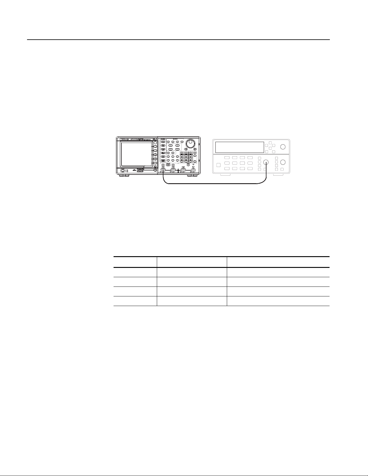
Adjustment Procedures
Frequency counter
50 Ω BNC coaxial cable
CH1 Output
AFG3000 series
Inputs
Reference Clock
This procedure adjusts the frequency accuracy of the arbitrary/function generator.
For any model, only one frequency point of channel 1 is adjusted.
1. Connect the arbitrary/function generator to the frequency counter as shown in
Figure 5-1.
Figure 5-1: Reference Clock adjustment
2. Push the Default front-panel button and OK menu button to recall the
arbitrary/function generator default setup.
3. Set up the arbitrary/function generator using the following steps:
Select menu Setting Operation
Function Sine Sine (front)
Frequency 1.000000 MHz Frequency/Period (front)
Amplitude 1.00 Vpp Amplitude/High (front)
Channel 1 Output On On (front)
4. Push the Utility > -more- > -more- > Service Menu >
Manual Calibration > -more- > Reference Clock buttons. Ref Clock value
is selected.
5. Adjust the Ref Clock value with the rotary knob so that the frequency counter
reading is between 0.999999 MHz and 1.000001 MHz.
6. Push the Save menu button to save the adjusted value.
5-4 AFG3000 Series Arbitrary/Function Generators Service Manual
 Loading...