

Page 1

Instructions Manual
016–1674–50
AFG310 & AFG320 Rackmount Kit
075-0288-50
www.tektronix.com
075028850
Page 2

Copyright © T ektronix Japan, Ltd. All rights reserved.
Copyright © T ektronix, Inc. All rights reserved.
T ektronix products are covered by U.S. and foreign patents, issued and pending. Information in this publication supercedes
that in all previously published material. Specifications and price change privileges reserved.
T ektronix Japan, Ltd., 5–9–31 Kitashinagawa, Shinagawa–ku, Tokyo 141–0001 Japan
T ektronix, Inc., P.O. Box 500, Beaverton, OR 97077
TEKTRONIX and TEK are registered trademarks of T ektronix, Inc.
Page 3

Table of Contents
Kit Description 1.............................................
Minimum Tool and Equipment List 1.....................................
Kit Parts List 1........................................................
Installation Instructions 3.....................................
Preparing the Instrument 3.............................................
Installing the Instrument into the Rack Adapter 7..........................
Installation into a Equipment Rack 11.....................................
Exploded View and Dimensional Drawing 13......................
016-1674-50 Rackmount Kit
i
Page 4

List of Figure
Figure 1 : Location of slit where minus driver may be inserted 4. . . . .
Figure 2 : Construction of the handle retainer (cross section) 4. . . . . .
Figure 3 : Construction of the handle retainer (cross section) 5. . . . . .
Figure 4 : Feet and rear cover removal 6. . . . . . . . . . . . . . . . . . . . . . . . .
Figure 5 : Attaching bracket and panel 8. . . . . . . . . . . . . . . . . . . . . . . . .
Figure 6 : Attaching bracket to two instruments 9. . . . . . . . . . . . . . . . .
Figure 7 : Attaching panel 10. . . . . . . . . . . . . . . . . . . . . . . . . . . . . . . . . . .
Figure 8 : Installation into the equipment rack 11. . . . . . . . . . . . . . . . . .
Figure 9 : Cooling for Rackmounted instruments 12. . . . . . . . . . . . . . .
Figure 10 : Rack adapter exploded view 13. . . . . . . . . . . . . . . . . . . . . . . .
Figure 11 : Dimensional drawing of rack adapter 14. . . . . . . . . . . . . . . .
ii
016-1674-50 Rackmount Kit
Page 5
Service Safety Summary
WARNING. The servicing instructions are for use by qualified personnel only. To
avoid personal injury, do not perform any servicing unless you are qualified to
do so. Refer to the General Safety Summary in the Service Manual of each
instrument before performing any service.
WARNING. Dangerous shock hazards may be exposed when the instrument covers
are removed. Before proceeding, ensure the mainframe power switch is in the off
position. Then, disconnect the instrument from the power source.
CAUTION. Many components within this instrument are extremely susceptible to
static-discharge damage. Service the instrument only in a static-free environment. Observe standard handling precautions for static-sensitive devices while
installing this kit. Always wear a grounded wrist and foot strap while installing
this kit.
Do Not Service Alone
Avoid Exposed Circuitry
Disconnect Power
Provide Proper Ventilation
Do not perform internal service on this product unless another person capable of
rendering first aid and resuscitation is present.
To avoid injury, remove jewelry such as rings, watches, and other metallic
objects. Do not touch exposed connections and components when power is
present.
Dangerous voltages or currents may exist in this product. Disconnect power cord
from the power source, remove battery (if applicable), and disconnect test leads
before removing protective panels, soldering, or replacing components.
To prevent product overheating, provide proper ventilation.
016-1674-50 Rackmount Kit
iii
Page 6

iv
016-1674-50 Rackmount Kit
Page 7
Kit Description
This kit includes parts and instructions for upgrading your AFG310/AFG320
instrument.
When newly installing Rackmount Kit, no special performance check is required.
Minimum Tool and Equipment List
The following table lists the tools you will need to upgrade the 016Ć1674Ć50
Rackmount Kit.
Tool Description
#2 Phillips tip Screwdriver Standard tool for M3 and M4 screws
FlatĆbladed screwdriver For removing the plastic cover on the handle bracket
Kit Parts List
The following table lists the parts included in the 016Ć1674Ć50 Rackmount Kit.
Number Quantity Part Number Description
1 ą1 ea 407Ć4575Ć00 BRACKET, RACK: EIA, STL
2ą1ea333Ć4276Ć00 PANEL, FILTER: AFG300, STL
3ą9ea211Ć0905Ć00 SCREW, MACHINE: M3 6MM L, PNH, STL, MFZN-C, CROSS REC
4ą1ea211Ć0959Ć00 SCREW, MACHINE: M4 5MM L, PNH, STL, MFZN-C, CROSS REC
5 ą1 ea 075Ć0288Ć50 Rackmount Instruction Sheet
016-1674-50 Rackmount Kit
1
Page 8

Introduction
2
016-1674-50 Rackmount Kit
Page 9
Installation Instructions
This section contains the following information:
H how to prepare your instrument to attach the rack adapter
H how to attach the rack adapter to your instrument
H Installation into equipment rack
Preparing the Instrument
This sub-section contains the following information:
H Handle Removal
H Feet Removal
H Rear Cover Removal
NOTE. All parts removed from the instrument in this procedure should be saved.
You will need some of them to reconvert the instrument to a standard version at a
later time.
Handle Removal
016-1674-50 Rackmount Kit
1. Insert the flat-bladed screwdriver into the slit between the block and the
cover. See Figure 1.
2. Release the latch of the cover using the flat-bladed screwdriver. See Figure 2
and refer to
CAUTION. The latch of the cover can be released by lifting it up ward about 5
mm. Do not lift the cover more than necessary when releasing the latch. If so the
nail at the opposite side of the cover can be broken.
3. Remove the cover by sliding it sideways to the handle. See Figure 2 and
refer to 2 .
4. Repeat step 1 through 3 for another cover to remove.
5. Using a #2 phillips tip screwdriver, remove the one screw (M4 10 mm)
securing the block and handle to the cabinet.
1 .
3
Page 10

Installation Introductions
6. Repeat step 5 for another screw to remove. Lift off the blocks and handle.
Location of Slit
where flatĆbladed
screwdriver may be
Location of Slit
where flatĆbladed
screwdriver may be
inserted.
Cover
Block
inserted.
Power Cable
Figure 1: Location of slit where flat-bladed screwdriver may be inserted
CAUTION. The latch of the cover can be released by lifting it up ward about 5
mm. Do not lift the cover more than necessary when releasing the latch. If so the
nail at the opposite side of the cover can be broken.
Cover
1
1
Block
Figure 2: Construction of the handle retainer (cross section)
Cross Section
of the Cover
2
Handle
4
016-1674-50 Rackmount Kit
Page 11

M4X10mm
Screw
Cover
Block
Installation Introductions
Cover
M4X10mm
Screw
Block
Handle
016-1674-50 Rackmount Kit
Figure 3: Construction of the handle retainer (cross section)
5
Page 12

Installation Introductions
Feet Removal
Rear Cover Removal
1. Using a #2 phillips tip screwdriver, remove the four screws (M3 8 mm)
securing the four feet to the cabinet. Lift off the four feet. See Figure 4.
1. Using a #2 phillips tip screwdriver, remove the two screws (M4 8 mm)
securing the rear cover to the instrument. See Figure 4.
2. Remove the rear cover.
3. Install the two screws removed in step 1 to its former screw holes and fix the
cabinet to the instrument.
M4X8mm
Screw
Foot
Foot
M3X8mm
Screw
M3X8mm
Screw
Foot
Rear Cover
Foot
M3X8mm
Screw
M4X8mm
Screw
M3X8mm
Screw
Figure 4: Feet and rear cover removal
6
016-1674-50 Rackmount Kit
Page 13

Installing the Instrument into the Rack Adapter
The following steps describe how to attach the Rack Adapter to the instrument
in preparation for installing it into a rack.
These procedures include two installation methods.
H Attaching Bracket
H Attaching Panel
Attaching Bracket
Procedure for Attaching Bracket to one Instrument
1. Set the instrument with the top down on the work surface and the front
facing you.
2. Put the bracket on the instrument and align the bracket screw holes with the
instrument screw holes. See Figure 5.
Installation Introductions
3. Attach the bracket to the instrument with four screws (M3 6 mm) using a
#2 phillips tip screwdriver.
016-1674-50 Rackmount Kit
7
Page 14

Installation Introductions
Bracket
Panel
M3X6mm
Screw
M3X6mm
Screw
Figure 5: Attaching bracket and panel
8
016-1674-50 Rackmount Kit
Page 15

Installation Introductions
Procedure for Attaching Bracket to two Instruments
1. Set the two instruments side by side with the top down on the work surface
and the front facing you.
2. Put the bracket on the two instruments and align the bracket screw holes
with the instruments screw holes. See Figure 6.
3. Attach the bracket to the instruments with eight screws (four M3 6 mm
screws per one instrument) using a #2 phillips tip screwdriver.
Bracket
M3X6mm
Screw
M3X6mm
Screw
016-1674-50 Rackmount Kit
Figure 6: Attaching bracket to two instruments
9
Page 16
Installation Introductions
Attaching Panel
If the bracket is attached with two instrument, omit the following procedure for
attaching panel.
1. Put the panel next to the instrument as in the Figure 5 and align the panel
screw holes with the bracket screw holes.
2. Attach the panel to the bracket with two screws (M3 6 mm) using a #2
phillips tip screwdriver.
3. Set the instrument attached to the bracket with the bottom down on the work
surface and the front facing you.
4. Attach the panel to the instrument with one screw (M4 5 mm) using a #2
phillips tip screwdriver. See Figure 7.
5. Install one screw (M3 6 mm) from the right side of the bracket to fix the
panel using a #2 phillips tip screwdriver.
10
M4X5mm
Screw
M3X6mm
Screw
Figure 7: Attaching panel
016-1674-50 Rackmount Kit
Page 17
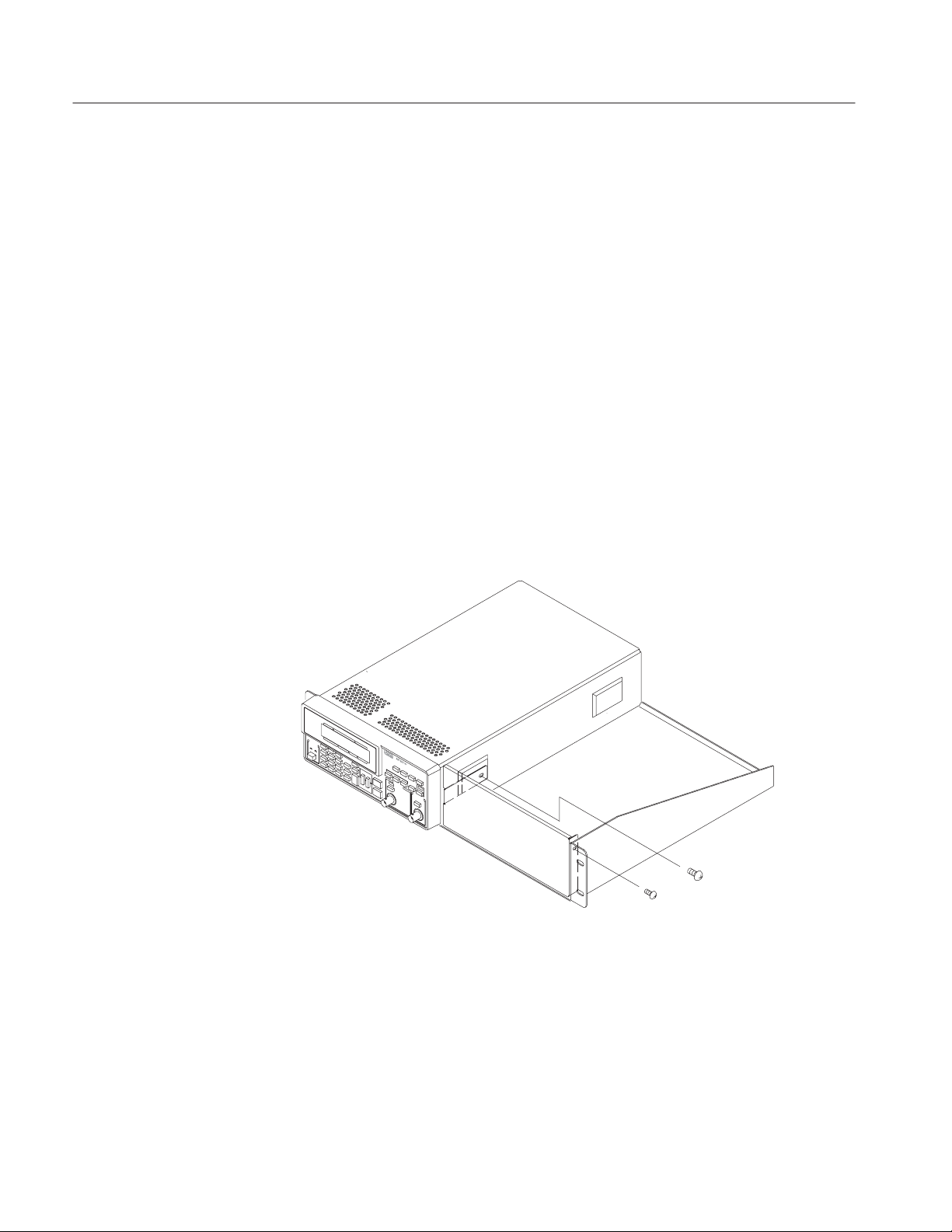
Installation into a Equipment Rack
This procedure provides instructions on how to install the adapter into an
equipment rack.
These procedures include two installation methods.
H Installing the adapted instrument into a equipment rack.
H Rear Panel Cabling.
Installing into a
Equipment Rack
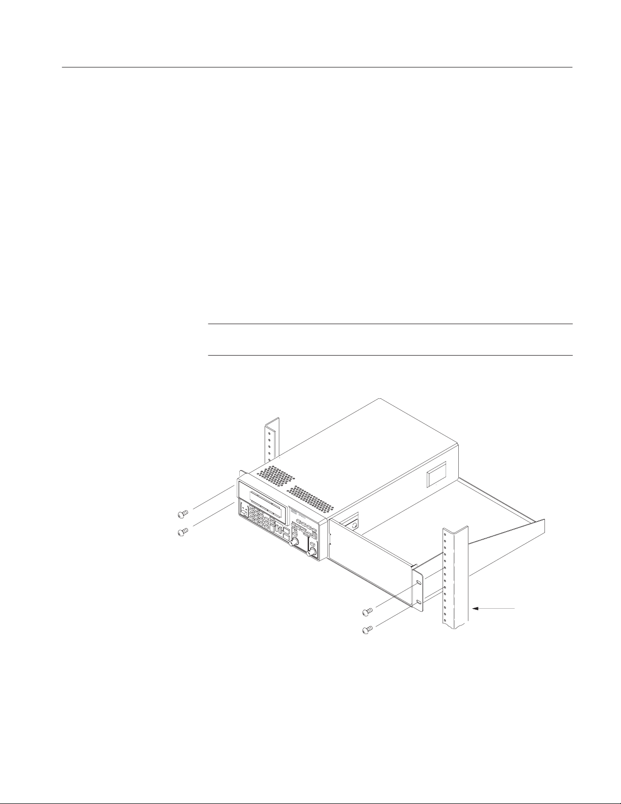
1. Select appropriate mounting holes on the equipment rack frame.
2. Attach the bracket to the equipment rack with four screws.
NOTE. These screws are not included in the rackmount kit (016-1674-00). Use
appropriate screws for your equipment rack.
Installation Introductions
Screw
016-1674-50 Rackmount Kit
Screw
Frame Rack
Figure 8: Installation into the equipment rack
11
Page 18
Installation Introductions
Rear Panel Cabling
Cooling
1. Connect the power cord to the rear of the instrument and power source.
Proceed the following procedure as necessary.
2. Connect the AM IN connector on the rear panel of the AFG310/320 through
a 50 W coaxial cable to an appropriate signal source.
3. Connect the SYNC OUT connector on the rear panel of the AFG310/320
through a 50 W coaxial cable to an appropriate equipment which will receive
the SYNC OUT signal.
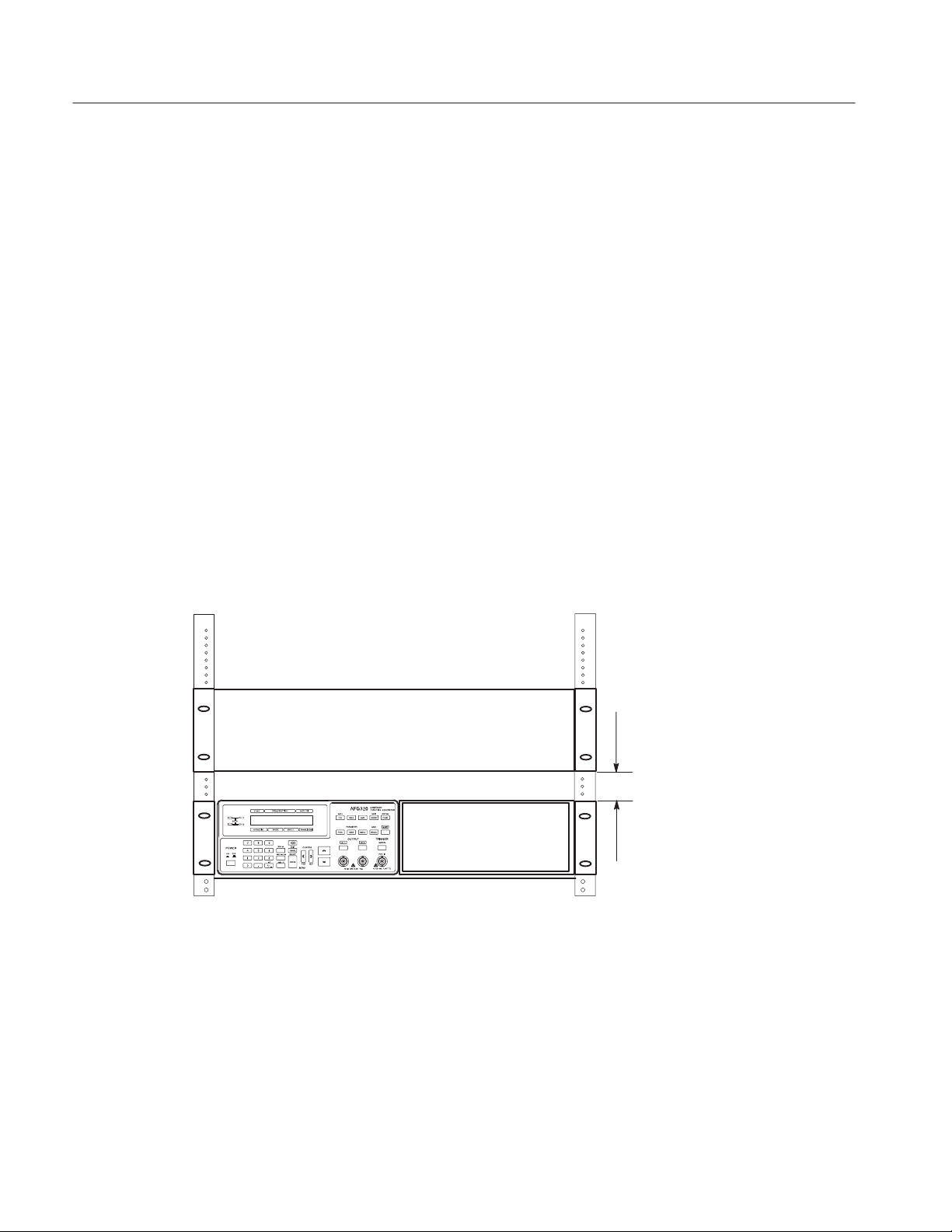
The cooling air goes inside from the air intakes at top and goes outside from the
rear.
Leave at least 5.1cm(2 inches) free on top when you install the another rackmounted instrument above the instrument.
See Figure 9.
12
At least the
space of
2 inches(5 cm)
is necessary.
Figure 9: Cooling for Rackmounted instrument(s)
016-1674-50 Rackmount Kit
Page 19
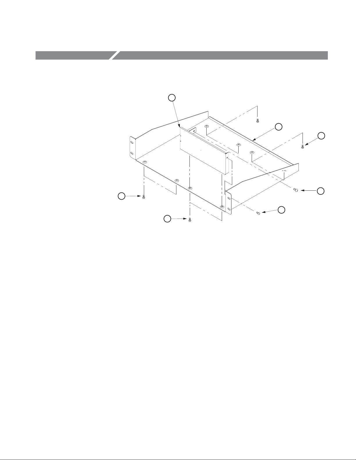
Exploded View and Dimensional Drawing
2
1
3
3
3
Figure 10: Rack adapter exploded view
4
3
016-1674-50 Rackmount Kit
13
Page 20
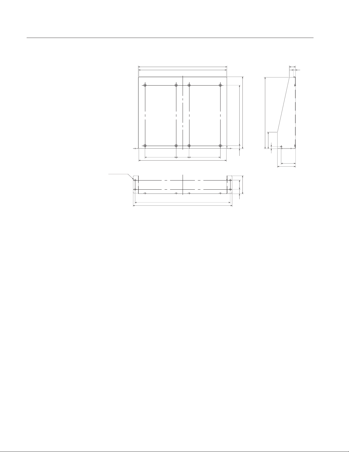
Replaceable Parts
433
427
152 63 152
427
6×12 ellipse
463.6
482.6
Figure 11: Dimensional drawing of rack adapter
294 350
14.5
88
44.5
21.8
30
10
347
80
10
70
88
(Unit: mm)
14
016-1674-50 Rackmount Kit
Page 21

Page 22

 Loading...