


xx
AFG3000 Series
ZZZ
Arbitrary Function Generators
Quick Start User Manual
*P077095702*
077-0957-02

xx
AFG3000 Series
ZZZ
Arbitrary Function Generators
Quick Start User Manual
www.tektronix.com
077-0957-01

Copyright © Tektronix. All rights reserved. Licensed software products are owned by Tektronix or its subsidiaries
or suppliers, and are protected by national copyright laws and international treaty provisions.
Tektronix products are covered by U.S. and foreign patents, issued and pending. Information in this publication
supersedes that in all previously published material. Specifications and price change privileges reserved.
TEKTRONIX and TEK are registered trademarks of Tektronix, Inc.
Additional trademark statements can be added here.
Contacting Tektronix
Tektronix, Inc.
14150 SW Karl Braun Drive
P.O. Box 5 0 0
Beaverton, OR 97077
USA
For product information, sales, service, and technical support:
In North America, call 1-800-833-9200.
Worldwide, visit www.tek.com to find contacts in your area.

Table of Contents
Environmental considerations ........................................
General safety summary .......................................................................................... vi
Preface .
Getting started..... . ..... . ..... . ..... . .... . . .... . ..... . ..... . ..... . ..... . ..... . ..... . ..... . ..... . ..... .... . . ..... . ... 1
Instrument interface, front panel, and rear panel............................................................... 24
Operating basics ..... ................................ ................................ .............................. 41
........................................................................................................... viii
Where to find more information...
Conventions used in this manual.......................................................................... viiii
General features..... .................................. ................................ ......................... 1
Before installation ...............................................................................
Operating requirements ......................................................................................
Standard accessories..................................................................
Optional accessories.... ................................ .................................. ..................... 5
Cleaning ........................................................................................................ 5
Power the instrument on and off ........................................ ................................ ..... 6
Change instrument settings at power-on .................................................................... 7
Erase instrument setups and waveforms from memory........... ................................ ......... 8
Perform instrument self test and self calibration ........................................................... 8
Select a local language ............... ................................ ................................ ........ 10
Protect your instrument from misuse. ................................ ................................ ...... 11
Floating ground ............. ................................ .................................. ................ 13
Protect your DUT............................................................................................. 14
Update your instrument firmware ........................................................................... 15
Connect to a network ..................... ................................ .................................. .. 17
Equivalent output circuits ..................................................................................
Overheat protection (AFG3011 / 3011C Only)............................................................
Front panel overview ......................................................................................... 24
Parts of the screen interface ................................................................................. 25
View button.................................................................................................... 26
Shortcut buttons............................................................................................... 28
Default setup.................................................................................................. 29
Select waveform.............................................................................................. 30
Select Run Mode.............................................................................................. 34
Adjust waveform parameters .......................................
Channel select (dual-channel mo
Output ON/OFF............................................................................................... 38
Rear panel .....................................................................................................
Quick tutorial: How to select a waveform and adjust parameters....................................... 41
Quick tutorial: How to generate a sine waveform ........................................................ 41
Quick tutorial: Instrument help system ............ ................................ ........................ 44
............................................................................ viii
del only)................................................................. 37
............................................ v
.............. 3
3
........................ 4
21
23
........................................
35
39
AFG3000
Series Quick Start User Manual i

Table of Contents
Generate a pulse waveform .................................................................................
Save/Recall arbitrary waveforms ...
Generate an arbitrary waveform ........................................................................... 48
Modify an
Generate noise/DC ......................................
Generate a burst waveform ................................................................................. 54
Sweep a waveform ...
Modulate a Waveform.......... ................................ ................................ .............. 58
Trigger Out .................... ................................ .................................. .............. 63
Adjusting Parameters of Two Channel Signals (dual-channel models only)........................... 65
Set up Load Impedance .... ................................ ................................ .................. 68
Invert Waveform Polarity .................. .................................. ................................ 69
Add Nois
Add Signal (AFG3100 and AFG3200 Series)............................................................. 71
Generating a Differential Signal ............................................................................ 72
External Reference Clock........ .................................. ................................ .......... 74
Synchronous Operation ...................................................................................... 75
USB flash drive...........................................
ity Menu................................................................................................... 78
Util
Save/Recall Instrument Setup ............................................................................... 80
Saving a Screen Image ......................... .................................. ............................ 81
Using the Security Menu..................................................................................... 81
ArbExpress ...................... .................................. ................................ ............ 84
Application Examples............................. ................................ ................................ 91
ssajous Patterns......................... ................................ .................................. .. 91
Li
Measurement of Filter Characteristics.. . ..... . ..... . ..... .... . . ..... . ..... . ..... . ..... . .... . . .... . ..... . ...
Motor Speed Control by Pulse-Width Modulation........................................................
Carrier Null (Frequency Modulation) .............. ................................ ........................
arbitrary waveform (Edit Menu) .............................................................. 49
........................................................................................
e ..... ................................ .................................. .............................. 70
....................................................................... 47
..................................................... 53
.......................................................77
45
55
92
92
93
ii AFG3000 Series Quick Start User Manual

List of Figures
Figure 1: Fuse and fuse adapter.................................................................................. 12
AFG3000 Series Quick Start User Manual iii

Table of Contents
List of Tables
Table i: Supported products ................
Table 1: Gen
Table 2: General features for C models .......................................................................... 2
Table 3: Standard accessories ................................ ................................ ..................... 4
Table 4: Optional accessories ..................................................................................... 5
eral features for regular and B models ............................................................ 1
.................................................................... viiii
iv AFG3000 Series Quick Start User Manual

Environmental Considerations
This section provides information about the environmental impact of the product.
Product End-of-Life
Handling
Restriction of Hazardous
Substances
Observe the following guidelines when recycling an instrument or component:
Equipment recycling. Production of this equipment required the extraction and
use of natural resources. The equipment may contain substances that could be
harmful to
end of life. To avoid release of such substances into the environment and to
reduce the use of natural resources, we encourage you to recycle this product in
an appropriate system that will ensure that most of the materials are reused or
recycled appropriately.
This product is classified as Monitoring and Control equipment, and is outside the
scope of the 2002/95/EC RoHS Directive.
the environment or human health if improperly handled at the product’s
This sym
Union requirements according to Directives 2002/96/EC and 2006/66/EC
on waste electrical and electronic equipment (WEEE) and batteries. For
information about recycling options, check the Support/Service section of the
Tektronix Web site (www.tek.com).
bol indicates that this product complies with the applicable European
AFG3000 Series Quick Start User Manual v

Environmental Considerations
General safet
To avoid fire or personal
injury
ysummary
Review the fo
this product or any products connected to it.
To avoid pot
Only qualified personnel should perform service procedures.
While using this product, you may need to access other parts of a larger system.
Read the safety sections of the other component manuals for warnings and
cautions r
Use proper power cord. Use only the power cord specified for this product and
certified for the country of use.
Ground the product. This product is grounded through the grounding conductor
of the power cord. To avoid electric shock, the grounding conductor must be
connected to earth ground. Before making connections to the input or output
terminals of the product, ensure that the product is properly grounded.
Observe all terminal ratings. To avoid fire or shock hazard, observe all ratings
and markings on the product. Consult the product manual for further ratings
information before making connections to the product.
llowing safety precautions to avoid injury and prevent damage to
ential hazards, use this product only as specified.
elated to operating the system.
Do not apply a potential to any terminal, including the common terminal, that
exceeds the maximum rating of that terminal.
Power disconnect. The power cord disconnects the product from the power source.
Donotblockthepowercord;itmustremain accessible to the user at all times.
Do not operate without covers. Do not operate this product with covers or panels
removed.
Do not operate with suspected failures. If you suspect that there is damage to this
product, have it inspected by qualified service personnel.
Avoid exposed circuitry. Do not touch exposed connections and components when
power is present.
Do not operate in wet/damp conditions.
Do not operate in an explosive atmosphere.
Keep product surfaces clean and dry.
Provide proper ventilation. Refer to the manual's installation instructions for details
on installing the product so it has proper ventilation.
vi AFG3000 Series Quick Start User Manual
General safety information
Terms in this manual
Symbols and terms on the
product
These terms may
WAR NI NG . Warning statements identify conditions or practices that could result
in injury or loss of life.
CAUTION. Caution statements identify conditions or practices that could result in
damage to this product or other property.
These terms may appear on the product:
DANGER in
the marking.
WARNING
read the marking.
CAUTION indicates a hazard to property including the product.
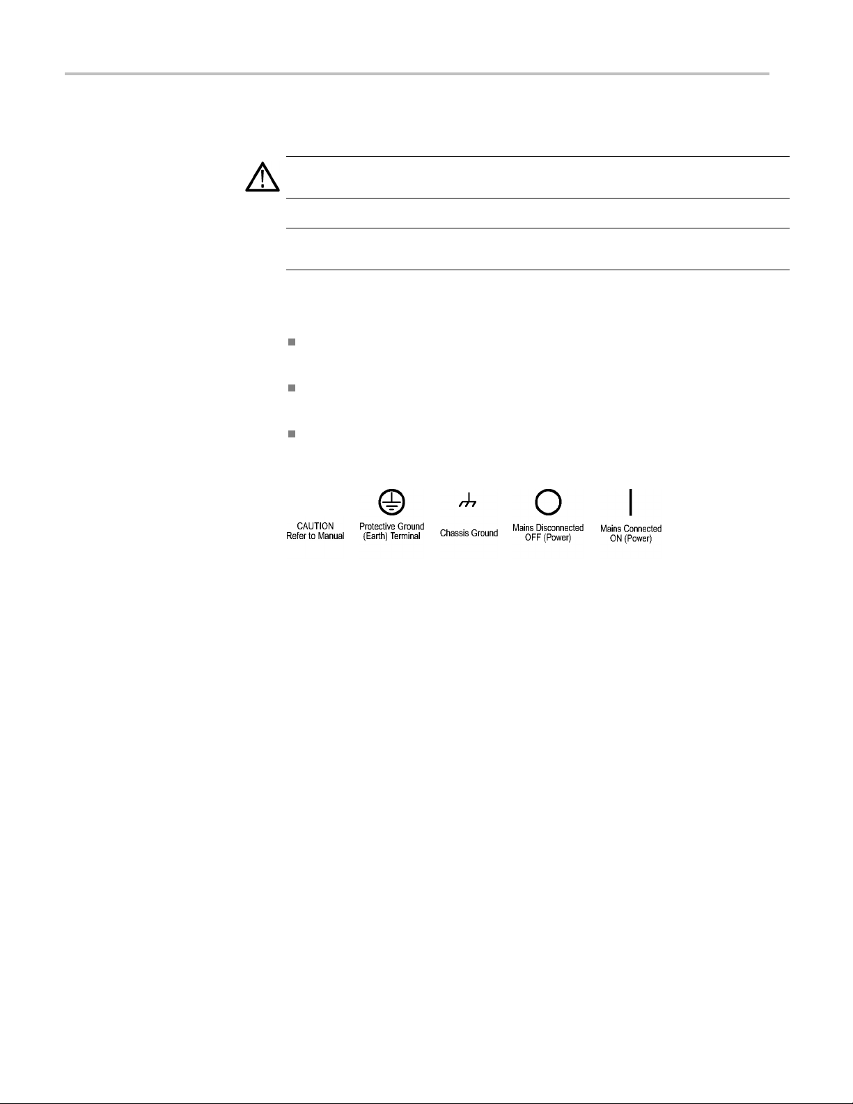
The following symbols may appear on the product:
appear in this manual:
dicates an injury hazard immediately accessible as you read
indicates an injury hazard not immediately accessible as you
AFG3000C and AFG3000 Series Specifications and Performance Verification
vii
Preface
This manual describes the installation and operation of Tektronix AFG3000 Series
Arbitrary Function Generators along with basic operations and concepts. The
following in
Table i: Supported products
AFG3011 AFG3021B AFG3011C
AFG3101 AFG3022B AFG3021C
AFG3102 AFG3022C
AFG3251 AFG3051C
AFG3252 AFG3052C
Where to find more information
struments are supported by this manual:
AFG3101C
AFG3102C
AFG3251C
AFG3252C
The following table lists related documentation available for your instrument.
The documentation is available on the Tektronix Web site (www.tek.com/
downloads).
Item Purpose Location
Safety and
Compliance
Instructions
uick Start User
Q
Manual
Built-in Help
Programmer
Manual
Service Manual Self-service and
Safety, compliance,
and basic power
information
Unpacking,
nstallation, Tutorials,
I
Operation, and
Overviews
UI Help and Operation
Menu Structures,
User Interface,
and Programming
Information
Performance test
AFG3000 Series Quick Start User Manual
viii
Preface
Item Purpose Location
Technical
Reference
ArbExpress
Software CD
NOTE. Please see the printed Safety and Compliance Instructions that were
shipped with your instrument for general safety summary, EMC compliance, and
safety compliance information.
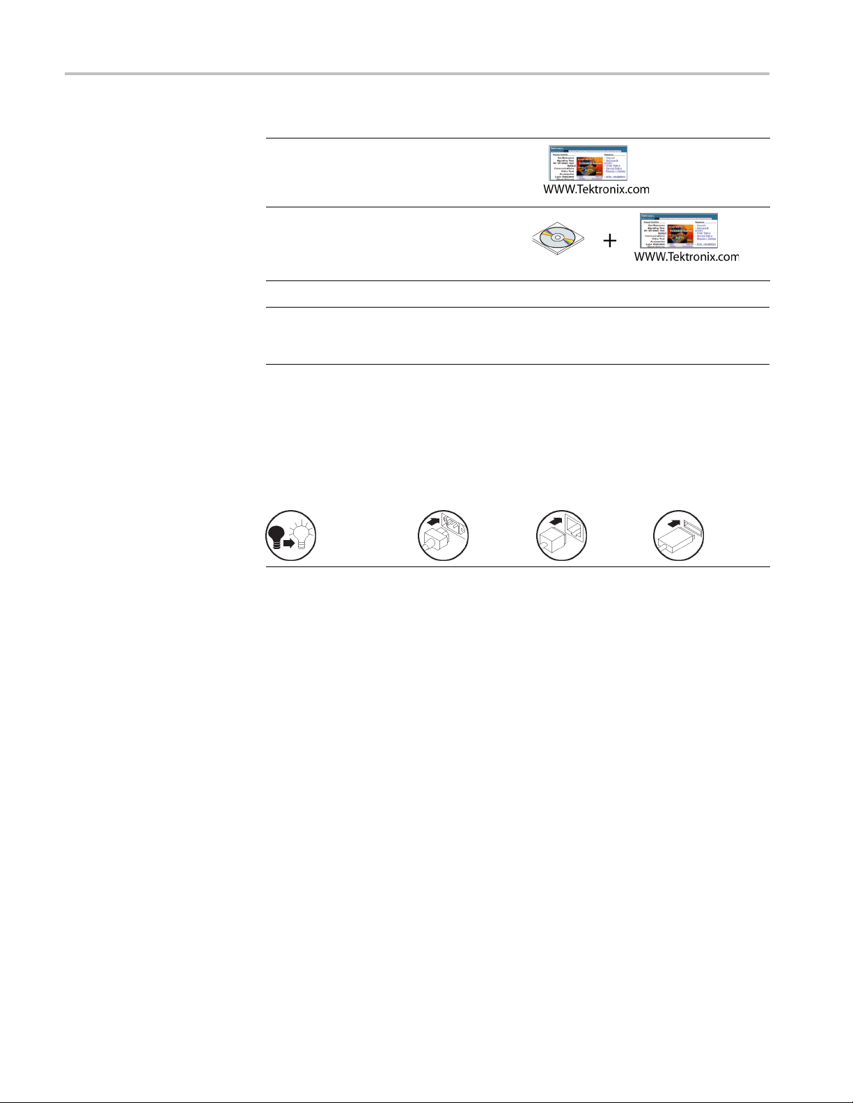
Conventions used in this manual
The following icons are used throughout this manual.
Specification
and performance
verification
procedures
Waveform cre
Import waveforms
from oscilloscope or
PC
s
ation
Front panel power
Connect power
Network
USB
The soft keys along the right side of the display are called bezel buttons in this
manual. In other documents, they may also be called option buttons or side-menu
buttons.
iiii AFG3000 Series Quick Start User Manual
v

Getting started
General featu
res
Each AFG3000 Series Arbitrary Function Generators offers the functionality of
three generators in one:
10 MHz to 240 MHz Function Generator
5 MHz to 120 MHz Pulse Generator
14-bit Arbitrary Waveform Generator
The following tables describe some of the general features of your ins trument. An
“X” means the feature is included with the model.
Table 1: General features for regular and B models
AFG3021B/
Feature AFG3011
Channel
Sine
Pulse 5 M Hz 12.5 MHz 50 MHz 120 MHz
Memory 2 to 131,072 2 to 131,072 2 to 16,384 >16,384 to
Sampling Rate 250 MS/s 250 MS/s 1 GS/s 250 MS/s 2 GS/s 250 MS/s
Amplitude 20 Vp-p 10 Vp-p 10 Vp-p 5 Vp-p
Display
Interface USB, LAN,
Ground
isolation
Synchronous
operation
Context-sensitive
Help sys tem
ArbExpress®
Software
1
10 MHz 25 MHz 100 MHz 240 MHz
Color Monochrome/
GPIB
XXX X
XXX X
XXX X
XXX X
AFG3022B AFG3101/ AFG3102 AFG3251/ AFG3252
1/2 1/2 1/2
2 to 16,384 >16,384 to
131,072
Color Color
Color
USB, LAN,
GPIB
USB, LAN, GPIB USB, LAN, GPIB
131,072
AFG3000 Series Quick Start User Manual 1

Getting started
Table 2: Genera
Feature AFG3011C
Channel
Sine
Pulse 5 MHz 25 M Hz 40 MHz 50 MHz 120 MHz
Memory 2 to
Sampling
Rate
Amplitude 20 Vp-p 10 Vp-p 10 Vp-p 10 Vp-p 5 Vp-p
Display
Interface USB, LAN,
Ground
isolation
Synchronous
operation
Context-sensitive
Help
system
ArbExpress®
Software
l features for C models
AFG3021C/
AFG3022C
1
10 MHz 25 MHz 50 MHz 100 MHz 240 MHz
131,072
250 MS/s 250 MS/s 1 GS/s 1 GS/s 250 MS/s 2 GS /s 250 MS/s
Color Color Color Color Color
GPIB
XX X X X
XX X X X
XX X X X
XX X X X
1/2 1/2 1/2 1/2
2 to 131,072 2 to 131,072 2 to
USB, LAN, GPIB USB, LAN, GPIB USB, LAN, GPIB USB, LAN, GPIB
AFG3051C/
AFG3052C
AFG3101C /
AFG3102C
16,384
>16,384
to
131,072
AFG3251C /
AFG3252C
2to
16,384
>16,384
to
131,072
2 AFG3000 Series Quick Start User Manual
Before installation
Inspect the instrument carton for external damage. If the carton is damaged,
notify the carrier.
Remove the instrument from its package and check that it has not been damaged in
transit. Verify that the carton contains the instrument and its standard accessories.
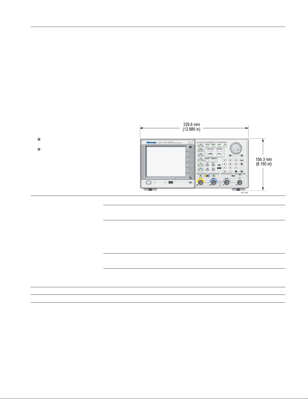
Operating requirements
Environmental
1. Place the instrument on a cart or bench, observing
clearance requirements:
Sides: 50 mm (2 in)
Rear: 50 mm (2 in)
2. Before operating, ensure that the ambient
temperature is between 0 °C to +50 °C (+32 °F
to +122 °F).
Getting started
Power Supply
Requirements
Requiremen
Source Voltage and Frequency
Power Consumption
t
CAUTION. To ensure proper cooling, keep both sides of the instrument clear of
uctions.
obstr
WAR NI NG . To reduce the risk of fire and shock, ensure that the mains supply
voltage fluc
tuations do not exceed 10% o f the operating voltage range.
AFG3000 series / AFG3000B series / AFG3000C series
100 V to 240
Less than 1
V, 47 Hz to 63 Hz; or 115 V, 360 Hz to 440 Hz
20 W
AFG3000 Series Quick Start User Manual 3

Getting started
Standard accessories
Unpack the instrument and check that you received all items listed as Standard
Accessories. Check the Tektronix Web site (www.tek.com) for the most
current information.
Table 3: Standard accessories
Description Tektronix part n um ber
AFG3000 Series Arbitrary Function Generators Safety and Compliance Instructions
AFG3000 Series Arbitrary Function Generators Programmer
Manual
AFG3000 Series Arbitrary Function Generators Service
Manual
AFG3000 Series Arbitrary Function Generators Specifications
and Performance Verification Manual
ArbExpress (Application Software for Tektronix Arbitrary Function Generators) Software CD
Power cord
North America (Option A0)
Universal Euro (Option A1)
United Kingdom (Option A2)
Australia (Option A3)
Switzerland (Option A 5)
Japan (Option A6)
China (Option A10)
India (Option A11)
071-3244-xx
077-0743-xx
077-0744-xx
077-0691-XX
063-3763-xx
161-0066-00
161-0066-09
161-0066-10
161-0066-13
161-0154-00
161-0298-00
161-0304-00
161-0400-00
1
These manu
Brazil (A12)
No power cord or AC adapter (Option A99)
als contain a language overlay for the front panel controls.
161-0357-00
---
4 AFG3000 Series Quick Start User Manual

Optional accessories
Getting started
The follo
Table 4: Optional accessories
Description Tektronix part number
50 Ω BNC cable, double-shielded, 91 cm (36 in)
50 Ω BNC cable, double-shielded, 250 cm (98 in)
GPIB interface cable, double-shielded, 200 cm (79 in)
Rackmount kit RM3100
Fuse adapter (BNC-P to BNC-R)
0.125 fuse set (contains three fuses)
NOTE. To ensure the EMC compliance listed in the Specifications, connect only
high quality shielded cables to this instrument. High quality shielded cables
typically are braid and foil types that have low-impedance connection to shielded
connectors at both ends.
eaning
Cl
Inspect the instrument as often as operating conditions require. To clean the
exterior surface, perform the following steps:
wing optional accessories are recommended for your instrument:
012-0482-XX
012-1256-XX
012-0991-XX
013-0345-XX
159-0454-XX
1. Remove loose dust on the outside of the instrument with a lint-free cloth. Use
care to avoid scratching the display.
2. Use a soft cloth dampened with water to clean the instrument. Use an aqueous
solution of 75% isopropyl alcohol for more efficient cleaning.
CAUTION. T
abrasive or chemical cleaning agents.
CAUTION. Avoid getting moisture inside the unit during external cleaning. Use
only enough cleaning solution to dampen the cloth or swab.
o avoid damage to the surface of the instrument, do not use any
AFG3000 Series Quick Start User Manual 5
Getting started
Power the inst
rument on and off
The following procedures show you how to apply p ower to the instrument and
turn it on and off.
Power on
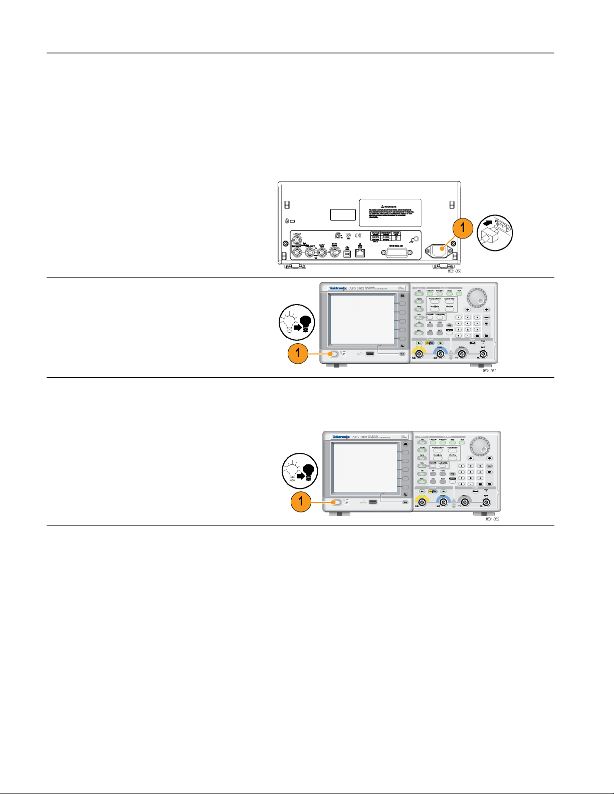
1. Insert the A C power cord into the power receptacle
on the rear panel.
2. Push the front-panel power button to power on the
instrument.
Wait until the front-panel display shows that the
instrument has passed all power-on self tests before
using the instrument.
Power off
1. Push the front-panel power button to power off the
instrument.
6 AFG3000 Series Quick Start User Manual
Getting started
Change instru
ment settings at power-on
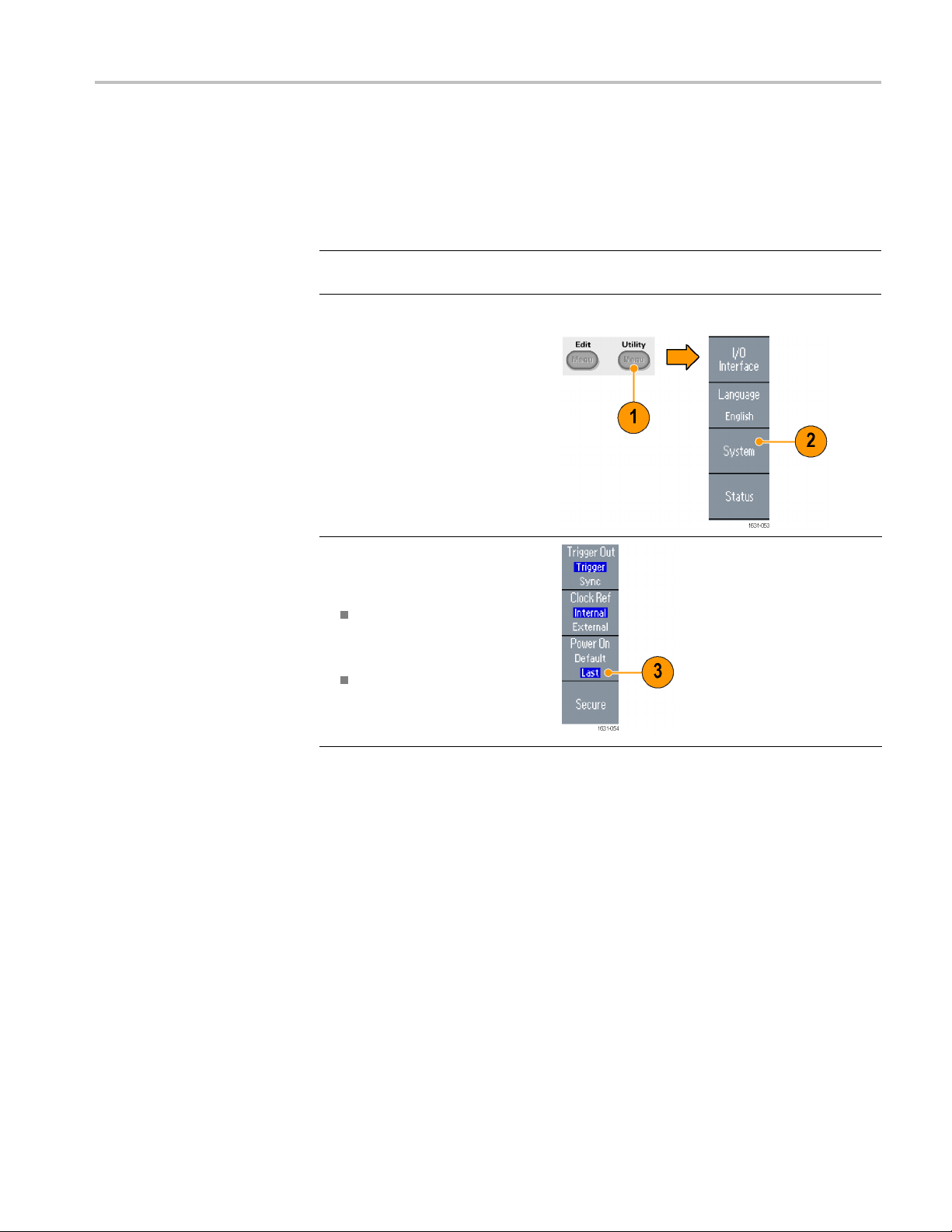
The default settings are restored when you power on the instrument. You can
change the power-on settings to the last powered-off settings from the Utility
menu using th
NOTE. You can restore the instrument to its default settings at any time by pushing
the front-panel Default button.
1. Push the front-panel Utility
button.
2. Push the System bezel button.
3. Push the Power On bezel button
to select from the following the
power on settings.
e following procedure.
Default restores the default
settings when the instrument
is powered on.
Last restores the same
settings as when the
instrument was last powered
off.
AFG3000 Series Quick Start User Manual 7
Getting started
Erase instrum
ent setups and waveforms from memory
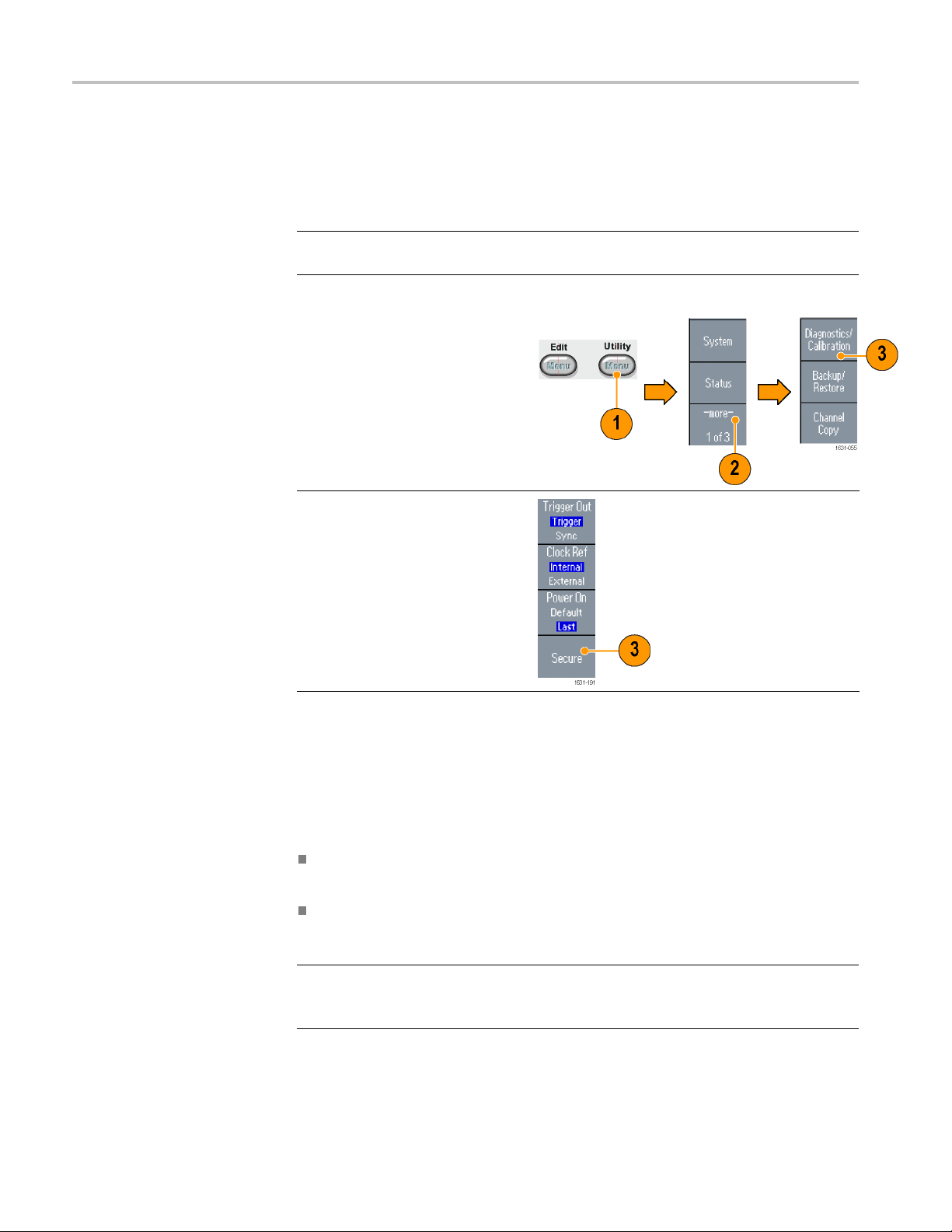
You can also erase all instrument setups and waveforms from the instrument
internal memory using the following procedure.
NOTE. You ca
erasing memory by pushing the front-panel Default button.
1. Push the front-panel Utility
button.
2. Push the System bezel button.
3. Push the Secure bezel button.
4. Push the OK bezel button to
erase all setups and waveforms
stored in internal memory, or
push the Cancel bezel button to
cancel the operation.
n restore the instrument to its default settings at any time without
Perform instrument self test and self calibration
nstrument performs a limited set of hardware tests at power-on. You can
The i
also perform the following manual diagnostics and/or self calibration using the
Utility menu:
Diagnostics (Self test): Perform the self test to verify that your instrument
is operating correctly.
Calibration (Self calibration): The self calibration mainly checks DC accuracy
using the internal calibration routines.
NOTE. If you need to verify that the instrument meets the warranted specifications,
do the complete set of performance verification procedures provided in the
Specifications and Performance Verification manual.
8 AFG3000 Series Quick Start User Manual
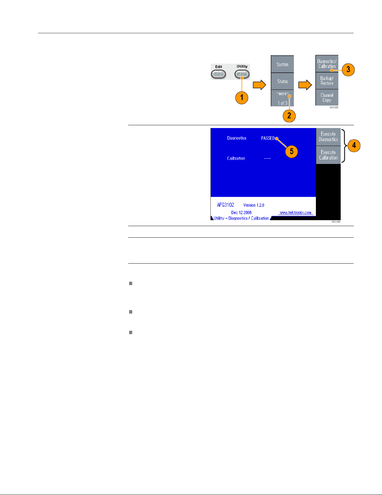
1. Push the front-panel Utility
button.
2. Push the -more
button.
3. Push the
Diagnostics
bezel button.
- bezel
/Calibration
Getting started
Quick Tips
4. To execute t
diagnostics, push the
Execute D iagnostics
bezel butto
To execute self calibration,
push the Execute
Calibrati
5. If Diagnostics completes
without any errors, the
message “
displayed.
CAUTION
he instrument
n.
on bezel button.
PASSED” is
. Do not power off the instrument while executing self calibration. If the
power is turned off during self calibration, data stored in the internal memory
maybelost.
Before executing self calibration, ensure that the ambient temperature is
between +20 °C and +30 °C (+68 °F to +86 °F). Allow a 20 minute warm-up
period before executing self calibration.
Disconnect all the cables from the instrument when you perform self test or
self calibration.
Perform self c alibration at least once a year to maintain DC accuracy. It is
recommended that the self calibration should be performed along with a
periodic check.
AFG3000 Series Quick Start User Manual 9

Getting started
Select a local
language
You can select the language you want displayed on the instrument screen.
1. Push the front-panel Utility
button.
2. Push the Language bezel button.
3. Select th
You can select from English,
French, German, Japanese,
Korean,
Traditional Chinese, and
Russian.
e desired language.
Simple Chinese,
Quick Tips
Wh
ou power on the instrument for the first time, English is selected by
en y
default. After you select a desired language, all the bezel menus, pop-up
messages, and built-in help are displayed in the specified language. The main
display area is not translated.
Use the front-panel overlay that corresponds to each local language.
10 AFG3000 Series Quick Start User Manual
Getting started
Protect your i
nstrument from misuse
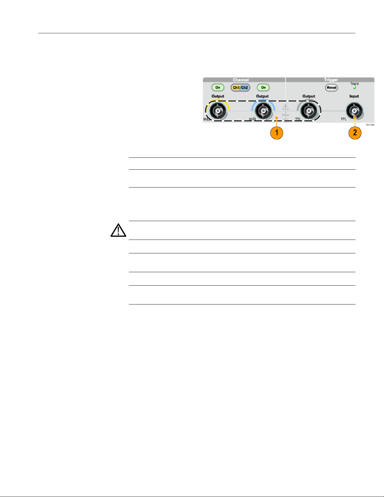
Check input and output
connectors
1. Locate the output
connectors on the
front panel. The
image shown here
shows the outputs.
2. Locate the input
connector on the
front panel. Some
instrument models
have more than one
input.
NOTE. When connecting a cable, be s ure to distinguish the input connector from
the output connectors to avoid making the wrong connection.
The instrument input and output connectors are floating inputs/outputs.
WAR NI NG . To avoid personal injury due to electric shock, do not apply voltages
in excess of 42 Vpk to any BNC connector ground or to the chassis ground.
CAUTION. Do not short output pins or apply external voltages to Output
connectors. The instrument may be damaged.
CAUTION. Do not apply excessive inputs over +5 V to Trigger Input connector.
The instrument may be damaged.
AFG3000 Series Quick Start User Manual 11
Getting started
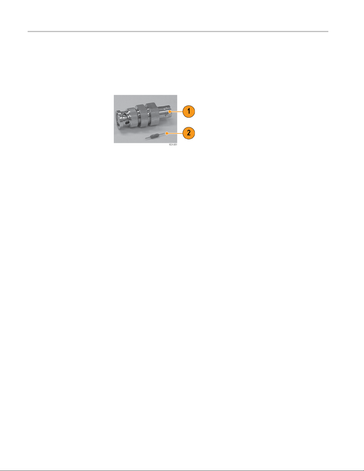
Use fuse adapter
The instrument
output or input connectors. To protect the output circuits, a fuse adapter is
provided as an optional accessory. When the instrument is used by students or
other inexperienced users, always attach the fuse adapter to the output connectors
to avoid damage. (See page 5, Optional accessories.)
Figure 1: Fuse and fuse adapter
1. Fuse adapter
2. Fuse
will be damaged if a large DC or AC voltage is applied to the
12 AFG3000 Series Quick Start User Manual
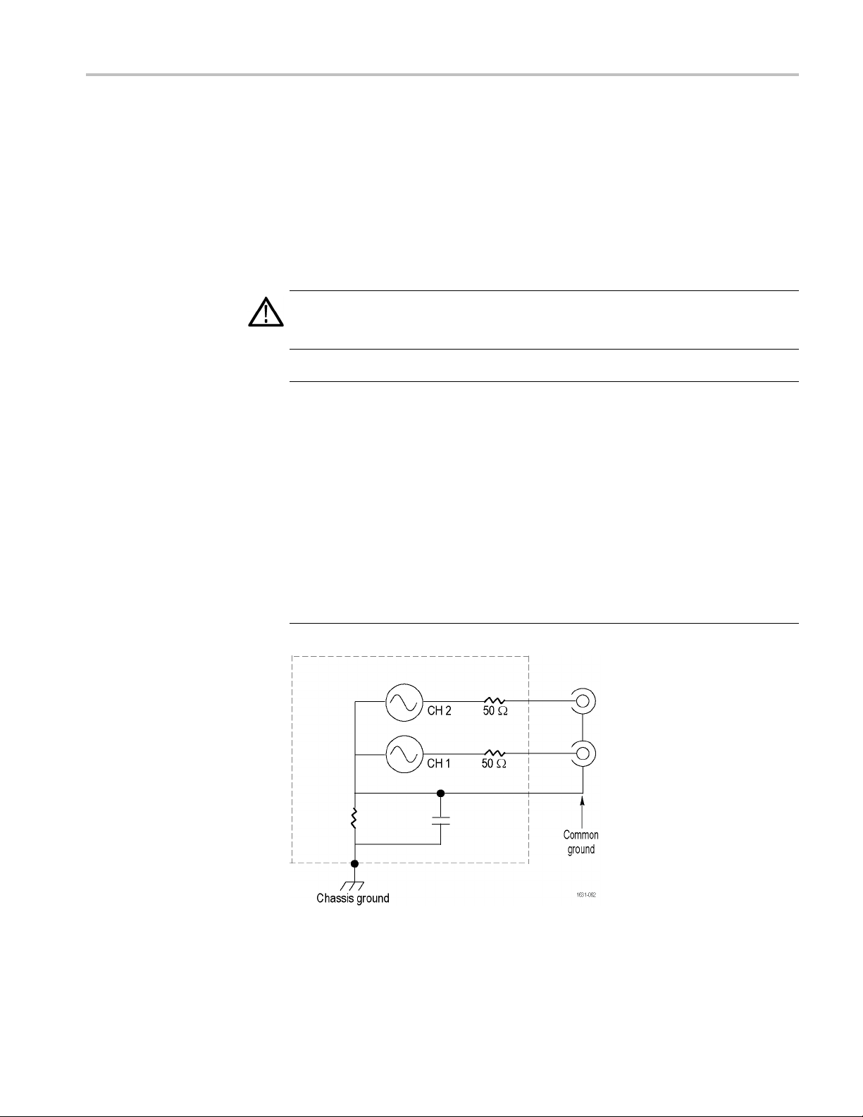
Floating ground
Getting started
Since the common (input and output channel c ommon) of the arbitrary function
generator is electrically isolated from the chassis ground (the instrument chassis
and ground line of the AC connector), you can make a floating connection
between the instrument and other equipment.
All the signal output connectors are connected to the common ground, and the
remote interface connector is connected to the chassis ground.
WAR NI NG . T
floating voltage and the output voltage of the instrument does not exceed 42 Vpk.
Do not touch the center of the BNC while the equipment is in use.
CAUTION. The maximum rated voltage between the chassis ground and common
ground is 42 Vp-p (DC + peak AC). When the potential voltage between the
chassis ground and common ground goes over 42 Vp-p, the internal protective
circuit will be activated to protect the circuits. However, higher voltage may c ause
the internal circuits in the instrument to be damaged.
When a potential voltage exists between the chassis ground and common ground,
a short circuit from output to ground causes the instrument internal fuse to open
and th
Tektronix Service Support.
When
short-circuiting between them may lead to excessive current flow and the internal
or external circuits may be damaged.
o prevent electrical shock, use this product so that the sum of the
e output is stopped. If the fuse opens, you need to contact your local
a potential voltage exists between the common ground and chassis ground,
AFG3000 Series Quick Start User Manual 13

Getting started
Protect your DUT
Use care when you connect the instrument Channel Output to your DUT (device
under test). To avoid damage to your DUT, the following preventive measure s are
provided. Follow these steps to s et the limit values for high level and low level.
1. Push the front-panel Top
Menu button. The Output
Menu is disp
bottom of the bezel menu.
Select Output Menu.
2. In this exa
Limit is set to 5.000 V,
and Low Limit is set to
-5.000 V.
3. Push the Limit bezel
button.
4. Select Hi
numeric keys or the
general purpose knob to
enter a v
Enter 50 mV for High
Limit, and -50 mV for Low
Limit.
layed at the
mple, High
gh Limit. Use
alue.
5. Push th
e front-panel
Sine button to display
the waveform parameter.
m that High and
Confir
Low voltage levels were
changed.
nnot enter any
You ca
values greater than
50 mV for High level.
NOTE. When you set limit values using Output Menu, a level indicator is
played at left end of graph area.
dis
14 AFG3000 Series Quick Start User Manual
Getting started
Update your in
strument firmware
You can use the front-panel USB flash drive connector to update your
instrument firmware.
CAUTION. Up
may damage your instrument if you do not follow all instructions carefully. To
prevent damage to the instrument, do not remove the USB flash drive or power
off the instrument during the update process.
NOTE. The screen images of the following procedure are provided as an example.
The actual screen display may be different depending on your instrument
configuration.
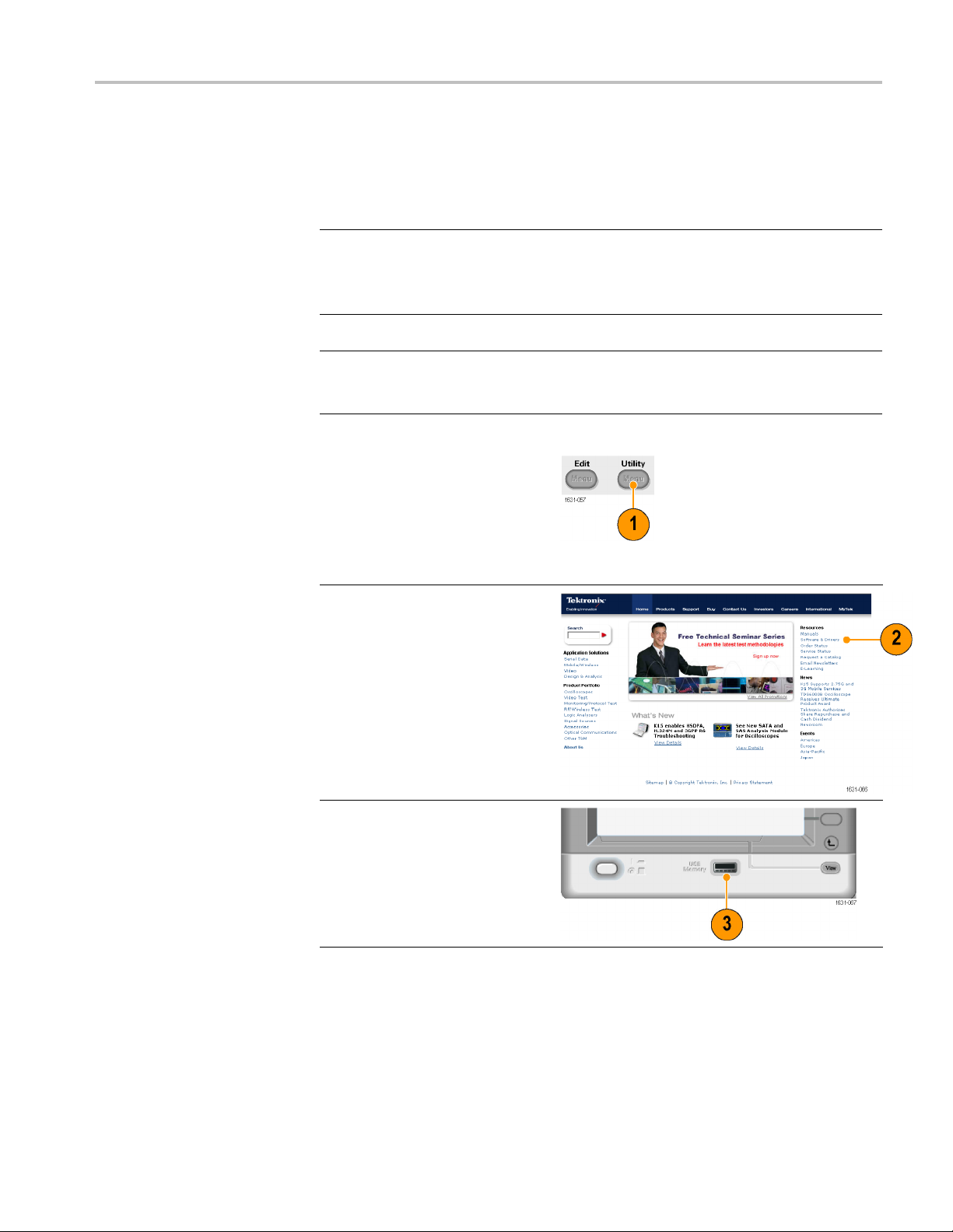
1. Push the
button to display the Utility
menu.
Versio
on the screen. Confirm the
firmware version of your
instru
2. Visit www.tektronix.com, and
check
firmware version. Download
the compressed zip file with the
most c
PC.
Unzip the downloaded file and
copy the file to the root directory
of your USB flash drive device.
front-panel Utility
n information is displayed
ment.
if Tektronix offers a newer
urrent firmware to your
dating your instrument firmware is a sensitive operation which
3. Insert the USB flash drive device
into the front-panel USB
connector and check that you
have saved the file to the root
directory of the USB flash
drive device.
AFG3000 Series Quick Start User Manual 15
Getting started
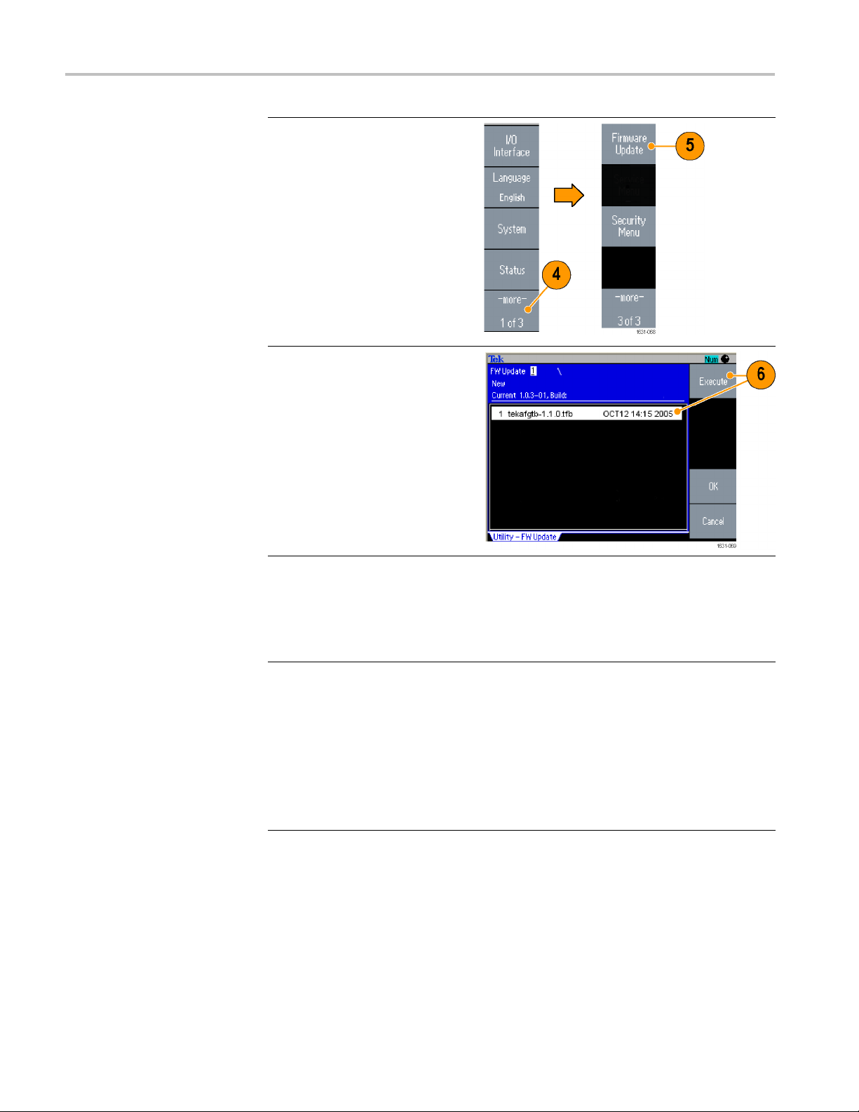
4. Push the -more
twice in the Utility menu.
5. The third page of the Utility menu
is displayed.
Update.
- bezel button
Select Firmware
NOTE. If the USB flash drive is
not inserted, the Firmware Update
bezel button is disabled.
NOTE. If Access Protection is on,
the Firmwar
disabled. You can read more about
access protection. (See page 81.)
6. Select the downloaded firmware
e Update bezel button is
file by rota
purpose knob, and then push
the Execute bezel button.
ting the general
7. Follow the on-screen
instructions.
8. Check that the clock symbol
at the top right of the screen
indicates the update process is
in progress.
CAUTION. A firmware update
usually takes approximately two
minutes. Do not remove the USB
flash drive during the update
process.
CAUTION. If you accidentally
removed the USB flash drive during
the update process, do not power off
the instrument. Repeat the
installation process from step 3.
16 AFG3000 Series Quick Start User Manual
Getting started
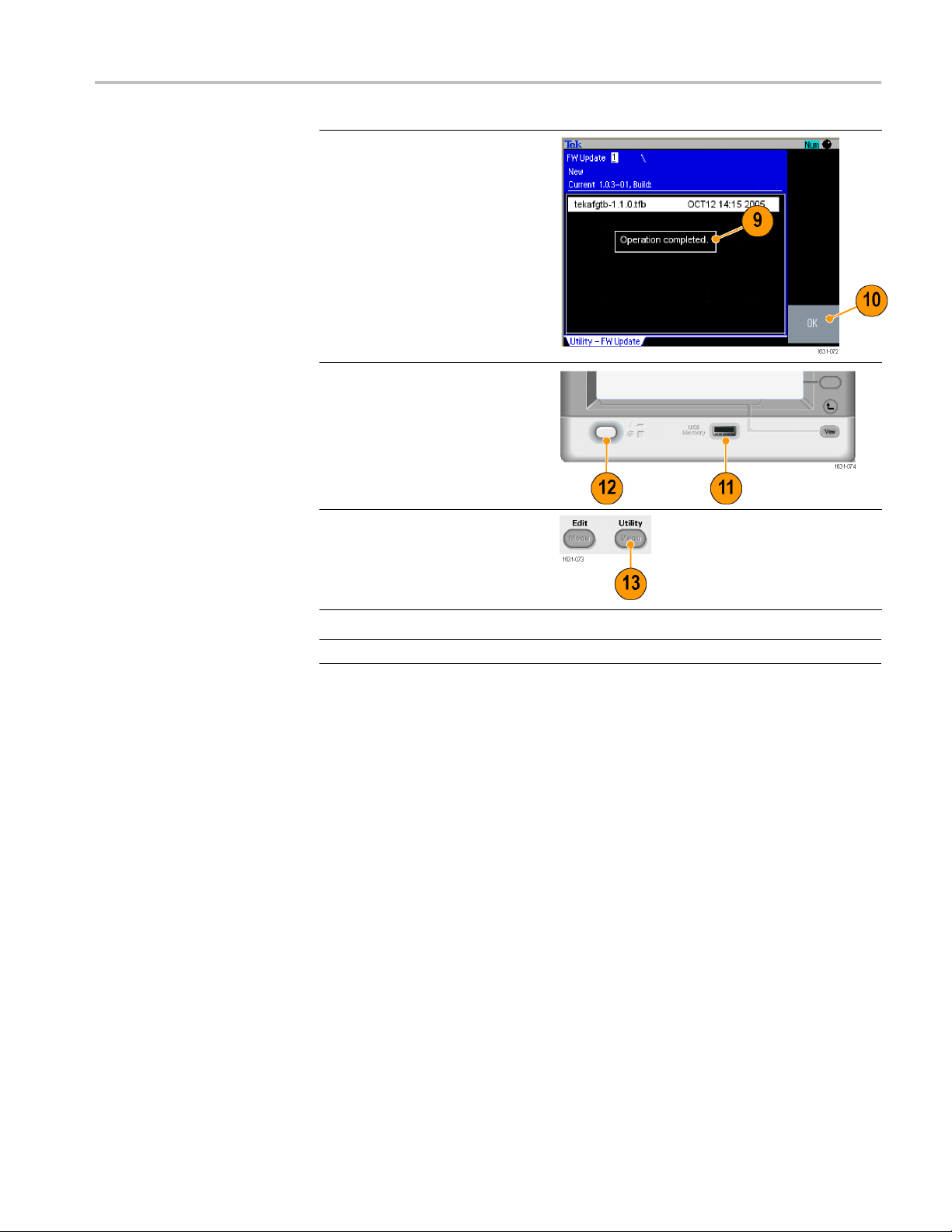
9. Wait until the
"Operation completed".
10. Push OK.
CAUTION. If “O
is not displayed, do not power off the
instrument. Repeat the installation
process from step 2 using a different
type of USB flash drive device.
11. Remove the USB flash drive
from the front-panel USB
connector.
12. Power the instrument off and
then back on.
13. Push the front-panel Utility
button to display the Utility
menu.
Confirm that the firmware has
been updated.
instrument displays
peration completed”
Conne
ct to a network
USB Interface
NOTE. You can protect access to firmware update using the Security menu.
The AFG3000 series arbitrary function genera tor communication inte rface allows
you to communicate with or remotely control your instrument. You can use a
Ethernet, or GPIB interface.
USB,
The USB interface requires no front panel or bezel menu operations to set up. Use
a USB cable to connect your instrument to a PC.
AFG3000 Series Quick Start User Manual 17

Getting started
hernet Setup
Et
To connect your instrument to a network, you must first obtain information from
your network administrator. The procedure for entering the Ethernet network
parameters depends on your network configuration. If your network supports
HCP (Dynamic Host Configuration Protocol), follow these steps:
D
1. Connect a LAN cable to
the LAN port on the rear
panel.
2. Push the front-panel
Utility button.
3. Push the I/
Ethernet bezel buttons.
O Interface >
4. The Ethernet Network
s menu is
Setting
displayed.
By selecting the DHCP
On, the i
set its network address
automatically through
DHCP.
nstrument can
18 AFG3000 Series Quick Start User Manual
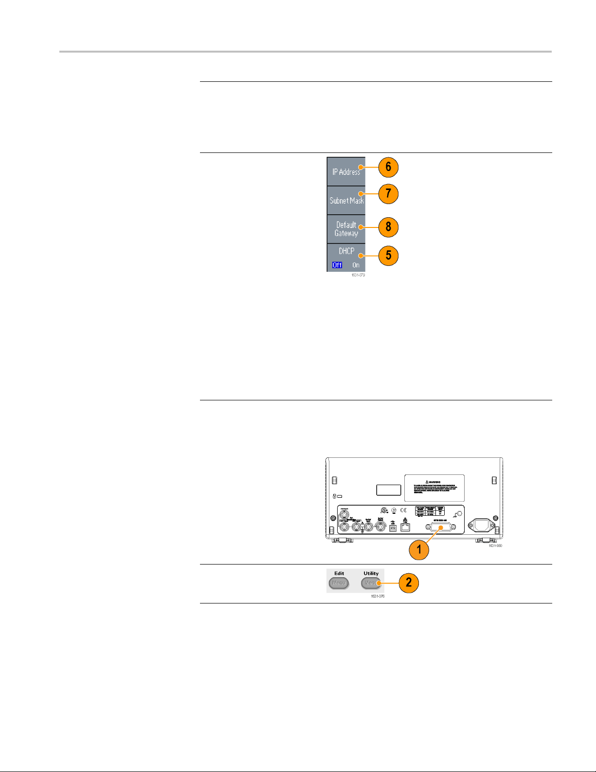
If you cannot establish
communication by setting
DHCP On, you ne
an IP Address manually and
a Subnet Mask if necessary.
Follow these
5. Display the Ethernet
Network Set
and select DHCP Off.
6. Push the IP Address
bezel butto
IP address. You need
to contact your network
administr
address to use.
7. Push the Subnet Mask
bezel but
Subnet Mask. Ask your
network administrator
whether a
required.
8. Push the Default Gateway
bezel bu
a gateway address.
Ask your network
admini
gateway address.
ed to set up
steps:
tings menu
n to enter an
ator to get the IP
ton to enter a
subnet mask is
tton to enter
strator for the
Getting started
GPIB Setup
To set the instrument GPIB interface, follow these steps:
1. Conne
2. Push the front-panel
ct a GPIB cable to
the rear panel GPIB port.
Utility button.
AFG3000 Series Quick Start User Manual 19

Getting started
3. Push the I/O Interface >
GPIB bezel buttons.
4. Push the Add
button to assign a unique
address to the instrument.
The GPIB ad
defines a unique address
for the instrument. Each
device con
GPIB bus must have a
unique GPIB address.
The G PIB a
be from 0 to 30.
5. Push the Configuration
bezel but
the instrument bus
communications on
and off.
Talk /Li
this mode to remotely
control the instrument
from an
computer.
Off Bus - Select this
mode to disconnect
the in
the GPIB bus.
ress bezel
dress
nected to the
ddress must
ton to toggle
sten - Select
external host
strument from
Quick Tip
Refer to the AFG
3000 Series Arbitrary Function Generators Programmer
Manual for information on remote control commands.
20 AFG3000 Series Quick Start User Manual

Equivalent output circuits
The following illustrations show the equivalent output circuits for the
AFG3000 series instruments:
Getting started
1. AFG3011 / 30
Output sig
not exceed ±20 V
when the >50 Ω load
impedance
2. AFG3021B / 3021C /
AFG3022
3051C / 3052C
Amplitude and offset of
the output signals are
not aff
impedance.
11C
nals do
is used.
B / 3022C /
ected by load
AFG3000 Series Quick Start User Manual 21

Getting started
3. AFG3101 / 3101C / 3102
/ 3102C
Output signals do
not exceed ±1
when the >50 Ω load
impedance is used.
Voltage over the
maximum lev
clipped.
Amplitude and offset
are affected when
you change
load impedance.
The maximum and
minimum le
not exceed ±10 V,
respectively.
4. AFG3251 / 3251C / 3252
/ 3252C
0V
el is
the
vels do
Output s
not exceed ±10 V
when the >50 Ω load
impedan
ignals do
ce is used.
22 AFG3000 Series Quick Start User Manual

Getting started
The following t
able shows the output window (maximum and minimum levels)
for sine waveform when you change the load impedance (L). Load impedance
will affect the output window.
L=50Ω L=HighZ
AFG3011 / 30
AFG3021B / 3021C / 3022B / 3022C / 3051C / 3052C
AFG3101 / 3101C / 3102 / 3102C
AFG325
11C
Maximum level
Minimum lev
(Maximum
amplitude)
Maximum level
Minimum level
(Maximum
amplitude)
Maximum
Minimum level
(Maximum
ude)
amplit
1 / 3251C / 3252 / 3252C
Maximum level
um level
Minim
(Maximum
amplitude)
el
level
10V-10V(20
5 V -5 V (10 Vp-p) 10 V -10 V (20 Vp-p)
10 V -10 V (10 Vp-p) 10 V -10 V (20 Vp-p)
5V-5V
Vp-p)
(5 Vp-p)
20 V -20 V (40
10 V -1
Vp-p)
0 V (10 Vp-p)
Overheat Protection (AFG3011 / 3011C Only)
instrument internal temperature is monitored in the AFG3011 and AFG3011C.
The
A warning message will appear if the internal t emperature reac hes a threshold
level, and signal output will automatically turn off. If the warning message
appears, check for the following conditions:
The ambient temperature requirement is being met.
The required cooling clearance is being met.
he instrument fan is working properly.
T
AFG3000 Series Quick Start User Manual 23

Instrument interface, front panel, and rear panel
Instrument in
terface, front panel, and rear panel
Front panel overview
The front panel is divided into easy-to-use functional areas. This section provides
you with a quick overview of the front panel controls and the screen interfac
The following figure shows the front panel of the dual-channel model.
e.
1. Bezel menu buttons
2. Top menu button
3. Function buttons
4. Shortcut buttons
5. Numeric keypad
6. Triggered LED is lit when the instrument receives an internal or external
trigger
7. Trigger input connector
8. Trigger output connector
9. Menu buttons
10. CH 1 and CH 2 output connectors
11. Return to previous menu button
12. View button
13. USB connector
14. Power on/off switch
24 AFG3000 Series Quick Start User Manual
Instrument interface, front panel, and rear panel
Lock or unlock the front
panel controls
If you need to lock the front panel controls, use the following remote command:
SYSTem:KLOCk[:STATe]
To unlock the front panel without u sing a remote command, push the front-panel
Cancel button twice.
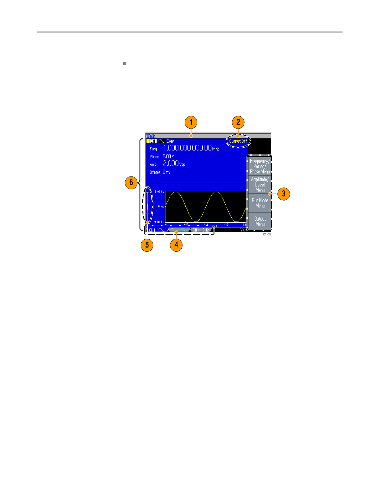
Parts of the screen interface
1. Message display area. A message that monitors hardware status such as clock
or trigger is displayed in this area.
2. Output status.
in this area. When you push the front panel channel output button to enable the
output, the message will disappear.
3. Bezel menu. When you push a front panel button, the instrument displays the
corresponding menu on the right side of the screen. The menu shows the options
that are available when you push the unlabeled bezel buttons directly to the right
of the screen. (Some documentation may also refer to the bezel buttons as option
buttons, side-menu buttons, or soft keys.)
4. Channel tabs. Alternate between channels being used.
5. Level meter. Amplitude level is displayed. The following figure describes the
level meter.
6. Main display area and View tab. Pushing the front-panel View button
toggles through the view format of the main display area. The view tabs
correspond with the current view format. The instrument can display three
different screen formats.
If the output is set to disable, Output Off message is displayed
AFG3000 Series Quick Start User Manual 25

Instrument interface, front panel, and rear panel
1. Shows maximum
amplitude level of your
instrument.
2. Shows the range of high
limit and low limit set by
the user.
3. Shows the amplitude level
that is currently selected.
View button
The instru
ment provides the following three screen view formats:
Waveform parameter and graph display
Graph comparison
Waveform parameter comparison
26 AFG3000 Series Quick Start User Manual

Instrument interface, front panel, and rear panel
1. To change the sc
display format, push the
front-panel View button.
2. The first format provides
the single channel
waveform parameters
and graph display.
(Dual-channel model
only): You can
toggle the CH1 and
CH2 information by
pushing the channel
select button.
When you push the View
button once, the view
format is changed to
the graph comparison
format.
Push the View button
again to display the
third format. T h is v iew
provides the channel
parameter comparison.
reen
Quick Tips
If the instrument is currently in the Save, Recall, Utility, Help, or Output
menu, p
ushing the View button will have no effect.
When the instrument is in the Edit menu, pushing the View button will toggle
en Edit text and graphical views. This is the only function of the
betwe
single-channel model view button.
AFG3000 Series Quick Start User Manual 27

Instrument interface, front panel, and rear panel
Shortcut butt
ons
Shortcut buttons are provided for experienced users. The shortcut buttons allow
you to select a setup parameter and enter a numeric value using the front panel
controls. By
using the shortcut buttons, you can select a waveform parameter
without using any bezel menu selection.
1. Shortcut buttons are located
below the Run Mode buttons on
the front panel.
In this example, use pulse
waveform.
2. If you push the Amplitude/High
shortcut button once, Amplitude
becomes
active.
Quick Tips
3. If you push the Amplitude/High
shortcut button again, High Level
becomes active.
You can also set parameters for
Frequency/Period, Offset/Low,
Duty/Width, or Leading/Trailing
inthesameway.
ou push the Phase | Delay shortcut button, Delay becomes active. Pushing
If y
Phase | Delay again will have no effect, because there is no phase parameter
in the pulse parameter menu.
The Duty/Width and Leading/Trailing shortcut buttons are functional only
when the instrument is in the pulse parameter menu.
28 AFG3000 Series Quick Start User Manual

Default Setup
Instrument interface, front panel, and rear panel
When you want to restore the instrument settings to the default values, use the
front-panel Default button.
1. Push the front-panel Default
button.
2. Aconfirmation pop-up message
appears on the screen.
Push OK to re
settings.
Push Cancel to cancel the recall.
call the default
Quick
Tips
3. If you select OK, the instrument
displays a 1 MHz frequency,
1Vp-pam
as the default setup.
plitude sine waveform
The AFG3000 Series Arbitrary Function Generators Programmer Manual
describes the
default setup settings in detail. This manual is available at
www.tek.com/downloads.
The front-panel Default button does not reset the following settings:
Language option
Power-on settings
System related settings (display contrast, screen saver, click tone, and
beeper)
Saved setups and arbitrary waveform data
alibration data
C
GPIB and Ethern
et setups
Access protection
3000 Series Quick Start User Manual 29
AFG

Instrument interface, front panel, and rear panel
Select Waveform
The instrument can provide 12 standard waveforms (Sine, Square, Ramp,
Pulse, Sin(
Decay, and Haversine). The instrument can also provide user-defined arbitrary
waveforms. You can create, edit, and save your custom waveforms.
You can also create modulated waveforms using the Run Mode Modulation
menus. The following table shows the combination of modulation type and the
shape of the output waveform.
x)/x, Noise, DC, Gaussian, Lorentz, Exponential Rise, Exponential
The following m
Run Mode
Continuous
Modulation
AM
FM
PM
FSK
PWM
Sweep
Burst
atrix shows which waveforms are allowed with each run mode.
Sine, Square, Ramp, Arb, Sin(x)/x,
Gaussian, Lorentz, Exponential Rise,
Exponential D
√√√
√
√
√
√
√
√√
ecay, H aversine
Pulse
√
Noise,
DC
NOTE. When the instrument outputs an Arb waveform, Vp-p of instrument setup
indicates the Vp-p value of normalized waveform data.
When the instrument outputs Sin(x)/x, Gaussian, Lorentz, Exponential Rise,
Exponential Decay, or Haversine, Vp-p is defined as twice the value of 0 to peak
value.
30 AFG3000 Series Quick Start User Manual

Instrument interface, front panel, and rear panel
To select an out
1. To select a con
sine waveform, push
the front-panel Sine
button and the
the Continuous button.
2. You can directly select
one of four st
waveforms from the
front-panel Function
buttons.
3. To select an arbitrary
waveform, push the
Arb button.
4. To select other
standard waveforms
such as Sin
Noise, DC, or
Gaussian, push the
More... b
then push the top
bezel button.
5. These are waveform
example
and Noise.
put waveform, follow these steps:
tinuous
n push
andard
(x)/x,
utton, and
s of Sin(x)/x
6. These are waveform
les of DC and
examp
Gaussian.
AFG3000 Series Quick Start User Manual 31

Instrument interface, front panel, and rear panel
7. These are waveform
examples of Lorentz
and Haversine
8. These are waveform
examples of
Exponenti
Exponential Decay.
.
al Rise and
32 AFG3000 Series Quick Start User Manual

Instrument interface, front panel, and rear panel
AFG3000 Series Quick Start User Manual 33
Instrument interface, front panel, and rear panel
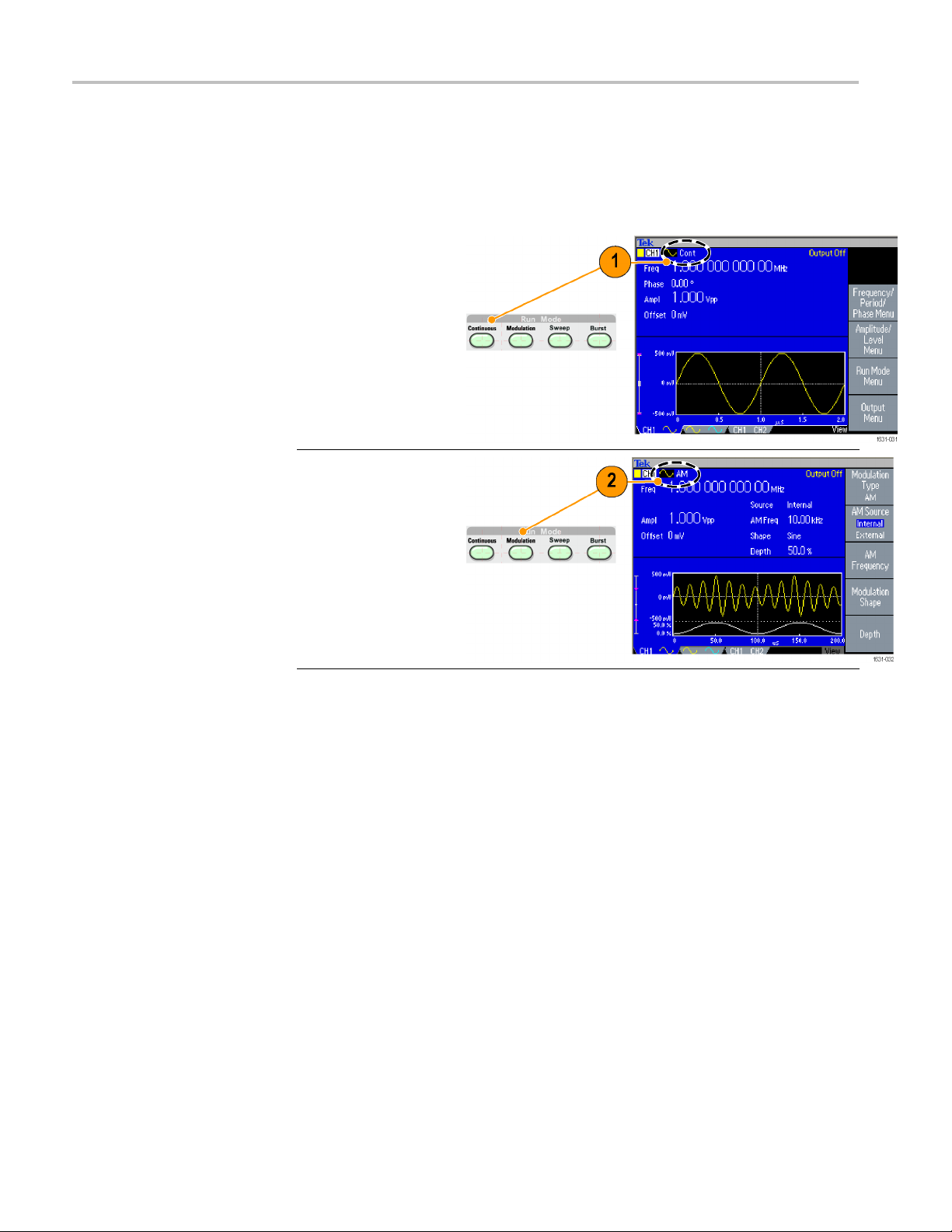
Select Run Mod
e
Push one of the four Run Mode buttons to select the instrument signal output
method.
1. The default
Run Mode is
Continuous.
You can read more about
changing waveform
parameters. (See
page 35.)
2. To select a
modulated
waveform, push the
Modulation button.
You can read more about
modulating waveforms.
(See page 58, Modulate
a Waveform.)
34 AFG3000 Series Quick Start User Manual
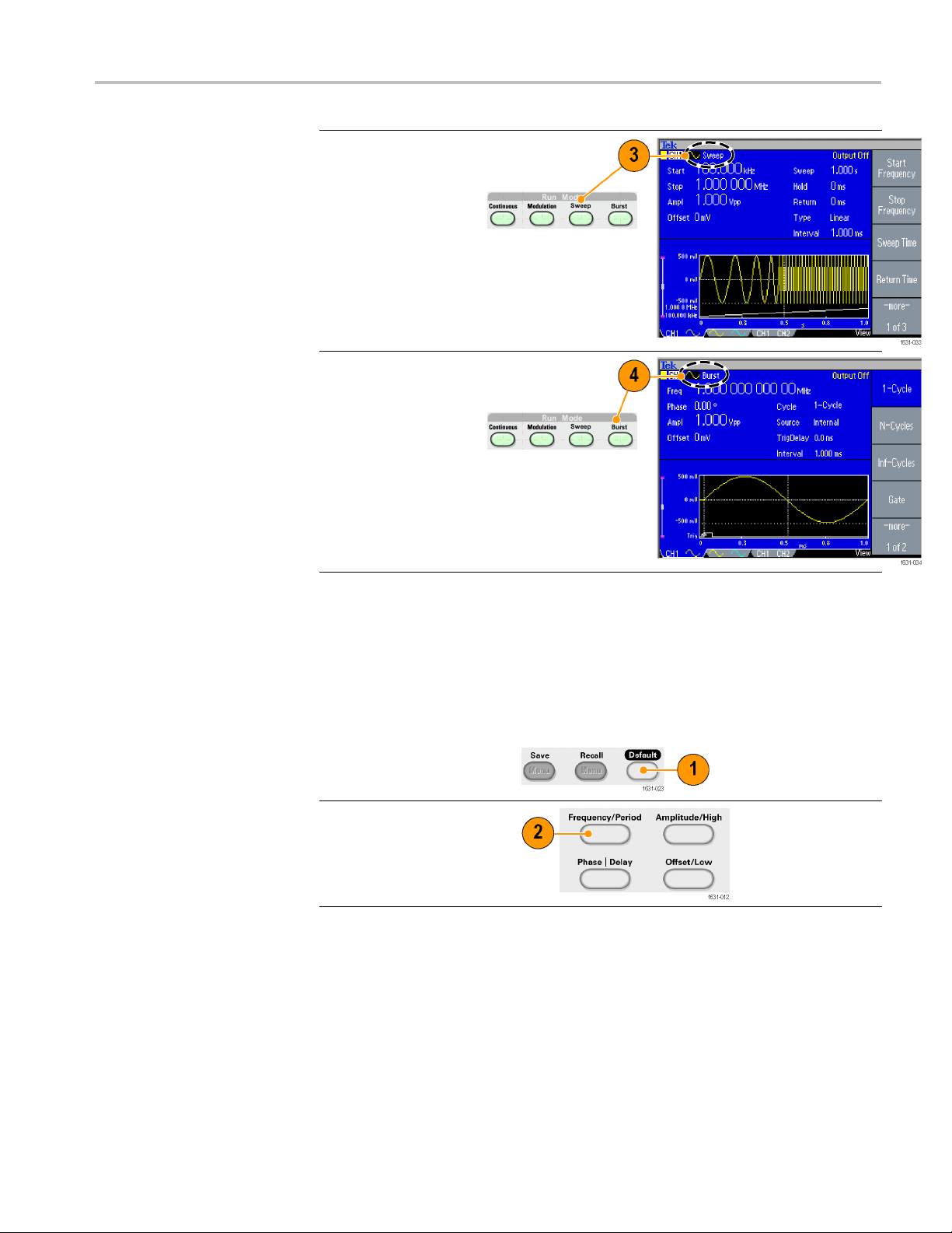
Instrument interface, front panel, and rear panel
3. To sel ect a swe
waveform, push the
Sweep button.
You can read mo
sweeping waveforms.
(See page 55.)
4. To select a burst
waveform, push the
Burst butt
You can read more
about Burst mode. (See
page 54.)
ep
re about
on.
Adjust Waveform Parameters
When you turn on your instrument, the default output signal is a 1 MHz sine
waveform with an amplitude of 1 Vp-p. In the following example, you can change
the frequency and amplitude of the original output signal.
1. Push the front-panel
Default button to display
the d
2. To ch
push the front-panel
Frequency/Period
sho
efault output signal.
ange frequency,
rtcut button.
AFG3000 Series Quick Start User Manual 35

Instrument interface, front panel, and rear panel
3. Frequency is n
You can change the value
using the keypad and
Units bezel me
can change the value
with the general purpose
knob.
4. Push the
Frequency/Period
shortcut bu
to toggle the parameter to
Period.
5. Next, change amplitude.
Push the Am
shortcut button.
6. Amplitude is now active.
You c an ch
using the keypad and
Units bezel menu, or
you can ch
using the general purpose
knob.
7. Push the
shortcut button again to
toggle the parameter to
High Le
You can change the
values of Phase and
inthesameway.
Offset
ow active.
nu, or you
tton again
plitude/High
ange the value
ange the value
Amplitude/High
vel.
8. To change the amplitude
units, push the -morebezel button to display
the second page.
9. Push the Units bezel
button to display units
selection bezel menu. By
default, Vp-p is selected.
36 AFG3000 Series Quick Start User Manual

Instrument interface, front panel, and rear panel
Quick Tip
The following c
onversion table shows the relationship between Vp-p, Vrms,
and dBm.
V
p-p
20.00 Vp-p 7.07 Vrms +30.00 dBm
10.00 Vp-p 3.54 Vrms +23.98 dBm
2.828 Vp-p 1.00 Vrms +13.01 dBm
2.000 Vp-p 707 mVrms +10.00 dBm
1.414 Vp-p 500 mVrms +6.99 dBm
632 mVp-p 224 mVrms 0.00 dBm
283 mVp-p 100 mVrms -6.99 dBm
200 mVp-p 70.7 mVrms -10.00 dBm
10.0 m Vp-p 3.54 mVrms -36.02 dBm
Channel Select (dual-channel model only)
1. Push the front-panel
Channel Select button to
the screen display.
control
You can toggle between
the two channels.
V
rms
dBm
NOTE. If you push the Channel Select button while you are in the Utility, Save,
Recall, or Help menu, the screen display returns to the previous view. The
channels do not toggle.
AFG3000 Series Quick Start User Manual 37

Instrument interface, front panel, and rear panel
Output ON/OFF
1. To enable signal output,
push the front-panel
Channel Output On
button. The button is lit
with an LED when it is in
the On state.
You c an co nfigure the
signal with the outputs
off. This will allow you
to minimize the chance
of sending a problematic
signal to a DUT.
2. (Dual-channel model
only) You can turn on or
off the signal output for
channel 1 and channel
2 independently.
You can enable one of the
two channels or enable
both of the two channels
at any time.
38 AFG3000 Series Quick Start User Manual

Rear Panel
Instrument interface, front panel, and rear panel
The following illustration shows the rear panel connectors for the instrument.
1. ADD INPUT: The ADD INPUT connector is provided with AFG3101 /
3101C / 3
external signal to the CH1 output signal.
2. EXT MOD
INPUT are independent. The signal input level of these connectors controls
modulation parameters.
3. EXT REF INPUT: This is a BNC connector for the external reference input.
When you want to synchronize multiple AFG3000 series arbitrary function
generators, or synchronize your arbitrary function generator and another
instrument, use the external reference input connector.
4. EXT REF OUTPUT: This is a BNC connector for the external reference
output. When you want to synchronize multiple AFG3000 series arbitrary
function generators, or synchronize your arbitrary function generator and
other instrument, use the external reference output connector.
an
5. USB: Used to connect a USB controller. (Type B)
6. LAN: Used to connect the instrument to a network. Connect a 10BASE-T
or 100BASE-T cable here.
7. GPIB: Used to control the instrument through GPIB commands.
8. Chassis Ground Screw: The chassis ground screw is used to ground the
instrument. Use a unified coarse screw (#6-32, 6.35 mm length or less).
102 / 3102C / 3251 / 3252 / 3252C. This connector lets you add an
ULATION INPUT (CH1 and CH2): The CH1 INPUT and CH2
9. Security Slot: Use a standard laptop computer security cable to secure your
instrument to your location.
AFG3000 Series Quick Start User Manual 39

Instrument interface, front panel, and rear panel
40 AFG3000 Series Quick Start User Manual

Operating basics
Quick tutorial: How to select a waveform and adjust parameters
If you are a beginning user, you can follow the steps described here to get
acquainted with how to select a waveform and adjust waveform parameters.
1. Press
2. Connect the CH1 Output of the instrument to the oscilloscope input with a
3. Select a waveform.
4. Enable the signal output.
5. Observe a waveform displayed on the oscilloscope screen.
6. Use the front-panel shortcut buttons on the instrument to select a waveform
7. Select Frequency as a parameter to be changed.
8. Change the frequency value using the numeric keys.
9. Change the waveform parameters using the general purpose knob and the
the power button to turn on the instrument.
BNC cable.
parameter.
arrow keys.
Quick tutorial: How to generate a sine waveform
If you are a beginning user, you can follow the steps described here to learn how
to generate a continuous sine waveform.
1. Connect the power
cord, and then push the
front-panel power on/off
switch to turn on the
instrument.
2. Connect a BNC
cable from the CH1
Output of arbitrary
function generator to
an oscilloscope input
connector.
3. Push the front-panel Sine
button, and then push
the Continuous button to
select a waveform.
AFG3000 Series Quick Start User Manual 41
Operating basics
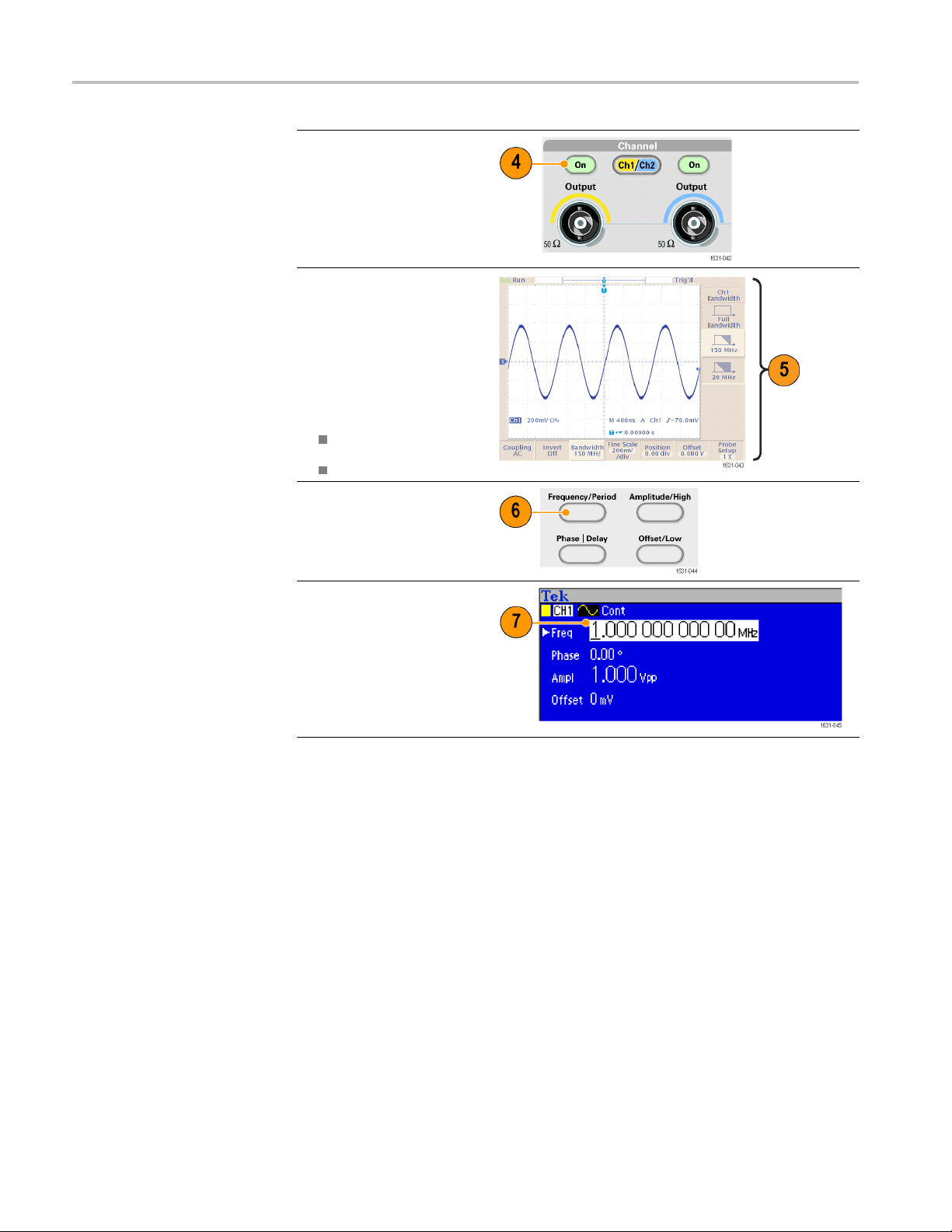
4. Push the front-panel
CH1 Output On button to
enable the out
5. Use the oscilloscope
auto-scali
display the sine waveform
on the screen.
If the instr
a default sine waveform,
you can manually set the
oscillosc
0.5 μs/div
put.
ng function to
ument outputs
ope as follows:
200 mV/di
6. To change
push the front-panel
Frequency/Period
shortcu
7. The
Frequency/Period/Phase
Menu is displayed and
Freq is selected. You
can now change the
frequency value.
the frequency,
t button.
v
42 AFG3000 Series Quick Start User Manual

8. To change the frequency
value, use the keypad
and Units beze
For example, if you enter
a value "2" using the
keypad, the b
will automatically change
to Units.
After enter
frequency value, push
the Units bezel button
or the front
button to complete the
entry.
You ca n cha
Amplitude, Phase, and
Offset values in the same
way.
9. You can also change the
frequenc
the general purpose knob
and the arrow keys.
To inc re
turn the knob clockwise.
To change a specificdigit,
it by pushing the
select
arrow keys. Then change
it by turning the knob.
l buttons.
ezel menus
ing the
-panel Enter
nge the
y value using
ase the value,
Operating basics
Quick Tips
Use the front-panel shortcut buttons to quickly select a waveform parameter.
You can also specify a waveform parameter by using bezel menu selection.
This method does not use the front-panel shortcut buttons.
When you specify a waveform parameter using the shortcut buttons or bezel
menu selection, an active para meter is displayed in green in the graph area.
AFG3000 Series Quick Start User Manual 43

Operating basics
Quick tutoria
l: Instrument help system
How to access the
instrument help system
The instrument h
elp system allows youtoaccessinformationaboutspecificmenu
items and instrument functions when you need help. You can access and navigate
this help system using front-panel buttons and knobs, and following on-screen
instructions as they appear. The individual help topics may contain links to other
topics, as well. These can be accessed by following the on-screen instructions.
You can follow the steps described here to access the instrument help system.
1. Push the front-panel Help
button to display the help
screen.
2. Turn the general purpose
knob to move the
highlight from one link to
another.
3. Push the Show Topic
bezel button to display
the topic corresponding
to the highlighted link.
4. Push the Index bezel
button to d isplay an Index
page.
5. Push the Exit bezel
button or any front-panel
button to remove the
Help text from the screen
and return to the graphic
or parameter display.
Ways to access and
navigate the instrument
help system
Push the Help button to display information (topic) about the last menu
displayed on the screen.
Turn the general purpose knob to m ove from page to page within a displayed
topic.
Push the Index bezel button to view the Help index page.
Push the Page Up or Page Down bezel buttons to search for the index page
that contains the topic you want to view.
Turn the general purpose knob to highlight a help topic in the index.
Push the Show Topic bezel button to display the topic from the index page.
Push the Utility button and then the Language bezel button to choose the
language in which you want the Help topics, bezel menus, and on-screen
messages to appear.
44 AFG3000 Series Quick Start User Manual
Operating basics
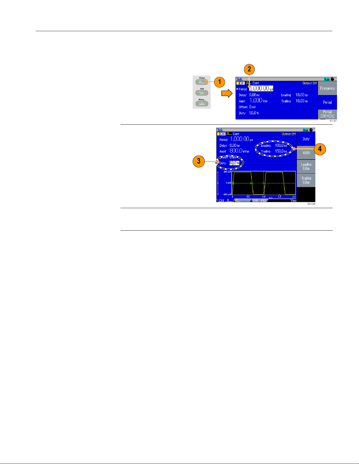
Generate a Pul
se Waveform
1. Push the front-panel
Pulse button to display
the Pulse screen.
2. Push the
Frequency/Period
shortcut button to select
Frequency or Period.
3. Push the Duty/Width
shortcut b
toggle between Duty
and Width.
4. Push the
Leading/Trailing
shortcut button to
toggle th
for Leading Edge and
Trailing Edge.
5. You can s
lead delay setting screen and adjusting the parameter as needed. You can also select
Lead Delay from the bezel menu.
utton to
e parameters
et the lead delay by pushing the Phase | Delay shortcut button to display the
Pulse waveform formulas
The following formulas are applied to leading edge time, trailing edge time, pulse
period, and pulse width of pulse waveforms.
lEdge (Leading Edge Time)
tEdge (Trailing Edge Time)
AFG3000 Series Quick Start User Manual 45

Operating basics
Maximum leadin
instance.
If runMode = Co
Temp1=0.8*2.0*width–tEdge;
Temp2=(period–width)*0.8*2.0–tEdge;
Temp3 = 0.625 * period.
Else:
Temp1=0.8*2.0*width–tEdge;
Temp2 = ( p
Temp3 = 0.625 * period.
Maximum trailing edge time. This value is the minimum of the three in each
instance.
If runMode = Continuous:
Temp1
Temp2=(period–width)*0.8*2.0–lEdge;
gedgetime. This value is the minimum of t he three in each
ntinuous:
eriod – leadDelay – width ) * 0.8 * 2.0 – tEdge;
=0.8*2.0*width–lEdge;
Else:
Temp3 = 0.625 * period.
Temp1=0.8*2.0*width–lEdge;
Temp2=(period–leadDelay–width)*0.8*2.0–lEdge;
p3 = 0.625 * period.
Tem
46 AFG3000 Series Quick Start User Manual

Save/Recall arbitrary waveforms
Operating basics
You can save up to
four arbitrary waveforms in the instrument internal memory.
To save more waveforms, use a USB flash drive
1. To recall or save an
arbitrary waveform, push
the front-panel Edit button
to display the Edit menu.
2. Select Read from...
to recall an arbitrary
waveform.
3. The Read Waveform
page is displayed.
4. To save waveforms,
select Write to... to
display the Write
Waveform page.
5. If you save a waveform
toaUSB flash
driveafile with the
extension TFW is saved.
6. You c
an also recall
waveforms by pushing
the front-panel Arb > Arb
form Menu bezel
Wave
buttons.
AFG3000 Series Quick Start User Manual 47
Operating basics
Quick Tips
Push the -moreLock/Unlock and the Erase menu.
The Lock/Unlo
overwrite.
Generate an Arbitrary Waveform
The instrument can output an arbitrary waveform that is stored in the internal
memory or a USB flash drive
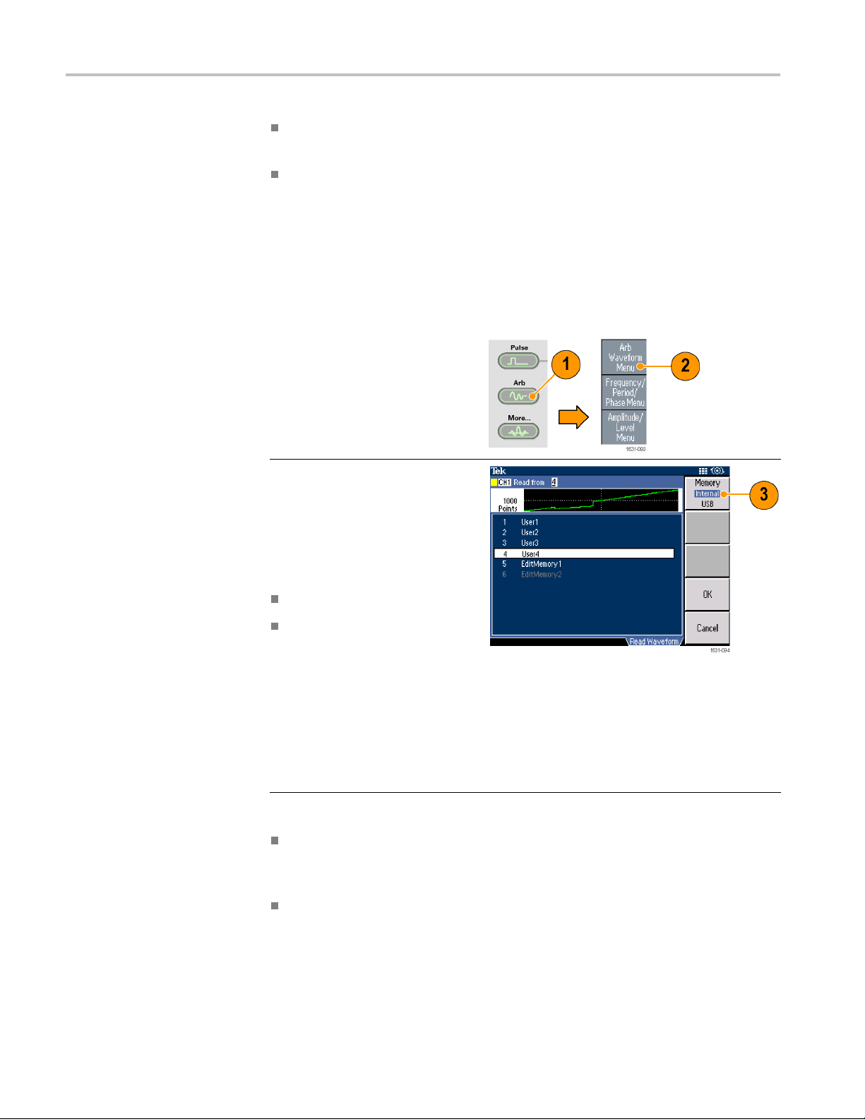
1. Push the fr
2. Push the Arb Waveform Menu
bezel button.
3. The Arb Waveform Menu is
ed. You can now browse
display
a list of waveform files in the
internal memory or USB flash
drive
Select Internal. You can specify
a file from the following:
bezel button in the Write to... submenu to display the
ck function allows you to lock the file against accidental
ont-panel Arb button.
Quick Tips
User 1, User 2, User 3, or User 4
Edit Memory 1 or Edit Memory 2
NOTE.
only available on dual-channel
instruments. Edit Memory 1 r elates to
Chan
to Channel 2.
Edit Memory 2 is
nel 1 and Edit Memory 2 relates
Use the front panel general
ose knob to scroll the files,
purp
then select a file and push OK.
File names are displayed only in English characters. If you use non-English
characters to name a file, these characters are replaced by Roman symbols
such as #, $, %.
Use the Write to... bezel menu in the Edit menu to copy a waveform file on
the USB flash drive to the internal memory.
48 AFG3000 Series Quick Start User Manual
Operating basics
Modify an Arbi
trary Waveform (Edit Menu)
To modify an arbitrary waveform, use the Edit Menu. The Edit Menu supports
several waveform edit functions and provides import or storage of edited
waveform dat
Memory 1 and Edit Memory 2). The Edit Menu also supports copying waveform
data between these two memories.
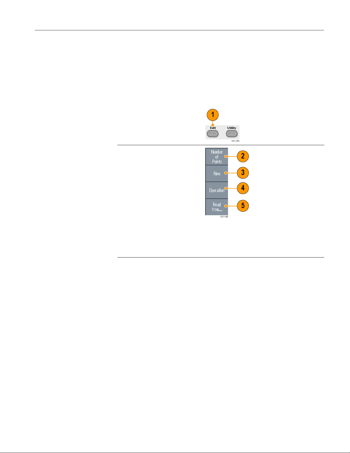
1. Push the fr
to display the Edit Menu.
2. Select Nu
the number of waveform points
to be edited.
3. Select Ne
waveform to Edit memory.
The written waveform has the
number o
Number of Points. One of five
waveform types (Sine, Square,
Ramp, P
selected.
4. Select Operation to display the
Operat
5. Select Read from... to specify
a memory location of waveform
data f
a. Dual-channel model instruments have two edit memories (Edit
ont-panel Edit button
mber of Points to set
w to write a standard
f points specified by
ulse, and Noise) can be
ions submenu.
rom Internal or USB.
AFG3000 Series Quick Start User Manual 49

Operating basics
6. Push Operation to display the
Operations submenu.
Push Line to display the Line
edit submenu
.
Push Data to d
Point edit submenu.
Push Cut to display the Cut
Data Points submenu.
7. Select Paste at Beginning to
append a wa
beginning of the edit waveform.
Select Paste at End to append a
waveform a
waveform.
8. Select Copy to EMEM1/EMEM2
to copy wa
Edit Memory 1 and Edit Memory
2. (This menu item is only
le on dual-channel
availab
instruments.)
9. Select Write to... to display a
submenu
to.
isplay the Data
veform at the
t the end of the edit
veform data between
to write waveform data
50 AFG3000 Series Quick Start User Manual
Operating basics
Arbitrary Waveform Edit
Example 1
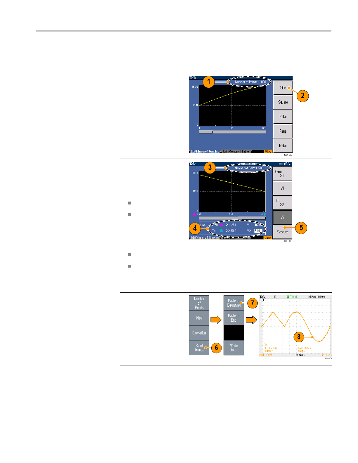
The following e
xample shows how to use the Line edit function. Paste a ramp
waveform before sine waveform:
1. Select Number of
Points to set the
number of waveform
points to 1000 points.
2. Select New and then
select Sine. Save this
waveform to User1.
3. Next, create a 500
point ramp waveform.
4. Select Operation and
select Line. Do the
following line edit:
X1: 1, Y1: 8191
X2: 250, Y2: 16382
Push Execute. Once
again, select Line from
Operation and perform
the following line edit:
X1: 251, Y1: 16382
X2: 500, Y2: 8191
5. Push Execute. Save
this waveform to
User2.
6. Next, paste a
waveform. Push Read
from... and select
User1.
7. Push Paste at
Beginning. Select
User2 waveform and
then select Paste.
8. The waveform shown
here is created.
AFG3000 Series Quick Start User Manual 51

Operating basics
Arbitrary Waveform Edit
Example 2
The following e
xample shows how to edit a waveform by data point. In this
example, you can add a noise spike to the sine waveform.
1. Push Read from... and
select Us er1.
2. Push the front-panel
View button to change
the screen to Table
display.
3. Push Operation and
select D a ta.
4. Perform the following
data point edit:
X: 250, Y: 8191
X: 251, Y: 8191
X: 750, Y: 8191
Quick Tips
X: 751, Y: 8191
5. After each data edit,
push Execute to
implement the edit
operation. Save this
waveform to User3.
6. This is an example of an
oscilloscope screen for
the User3 waveform.
If you edit arbi
trarywaveformdatainEditMemory1or2whilethe
instrument generates a waveform from edited Edit Memory, the edited
data will be automatically reflected to the generated waveform from the
corresponding channel.
Push the front-panel View button in the Edit Menu to toggle between edit
texts and graphical views.
Push the front-panel Channel Select button to toggle between the Edit
Memory 1 and Edit Memory 2 menus.
52 AFG3000 Series Quick Start User Manual

Generate Noise/DC
Operating basics
1. Push the f
More... button.
2. Push the More Waveform
Menu beze
3. Select Noise.
4. You can
parameters for Noise.
This is a sample of
Gaussi
on an oscilloscope screen.
5. Push DC to display DC
parameters.
ront-panel
l button.
set waveform
an Noise displayed
Quick Tip
You cannot modu
late or sweep noise or a DC w aveform.
AFG3000 Series Quick Start User Manual 53

Operating basics
Genera
te a Burst Waveform
To Generate a Triggered
Burst Waveform
The instrument can output a burst using standard waveforms such as sine, square,
ramp, and pulse, or arbitrary waveforms. The instrument allows you to use the
owing two types of bur st modes:
foll
Triggered Burst Mode. Aspecified number (burst count) of waveform cycles
are output when the instrument receives a trigger input from the internal trigger
source, an external trigger source, a remote command, or the Manual Trigger
button.
Gated Burst Mode. The instrument outputs a continuous waveform when an
effective gate signal is applied externally, when the Manual Trigger button is
depressed, when a remote command is applied, or during 50% of the selected
internal trigger interval.
The following example describes how to generate a double pulse using the burst
mode.
1. Select Pulse as an
output waveform
and then push the
front-panel Burst
button.
2. Confirm that 1-Cycle,
N-Cycles, or Inf-Cycles
is s e lected, which
means triggered burst
mode is enabled.
To generate double
pulse, set the burst
count (N-Cycles) to 2.
3. This is an example of
double pulse.
4. This waveform is a
trigger output signal.
54 AFG3000 Series Quick Start User Manual

Operating basics
To Generate a Gated Burst
Waveform
In the gated bur
st mode, the output is enabled or disabled based on the internal
gate signal or an external signal applied to the front-panel Trigger Input connector.
While the gate signal is true or the front-panel Manual Trigger button is pushed
in, the instrument outputs a continuous waveform.
1. Push the front-panel Burst
button to display the burst
menu.
2. Select Gate.
3. This is a sample
oscilloscope screen.
The top waveform is a
trigger output signal.
4. This is a gated waveform
sample.
Quick Tips
Sweep a Waveform
The instrument provides the following three trigger sources for Burst mode:
Internal or external trigger signal
Manual trigger
Remote command
Once Gate is selected, burst count parameters are ignored.
The Sweep outputs a waveform with the output s ignal frequency varying linearly
or logarithmically.
You can set the following parameters for Sweep:
Start frequency
Stop frequency
Sweep time
AFG3000 Series Quick Start User Manual 55

Operating basics
Return time
Center frequency
Frequency span
Hold time
1. Select a waveform and
then push the front-panel
Sweep button.
2. You can specify the
start frequency, stop
frequency, sweep time
and return time from the
sweep menu.
Return Time represents
the amount of time from
Stop Frequency to Start
Frequency.
Push the -more- button
to display the second
sweep menu.
56 AFG3000 Series Quick Start User Manual
Operating basics
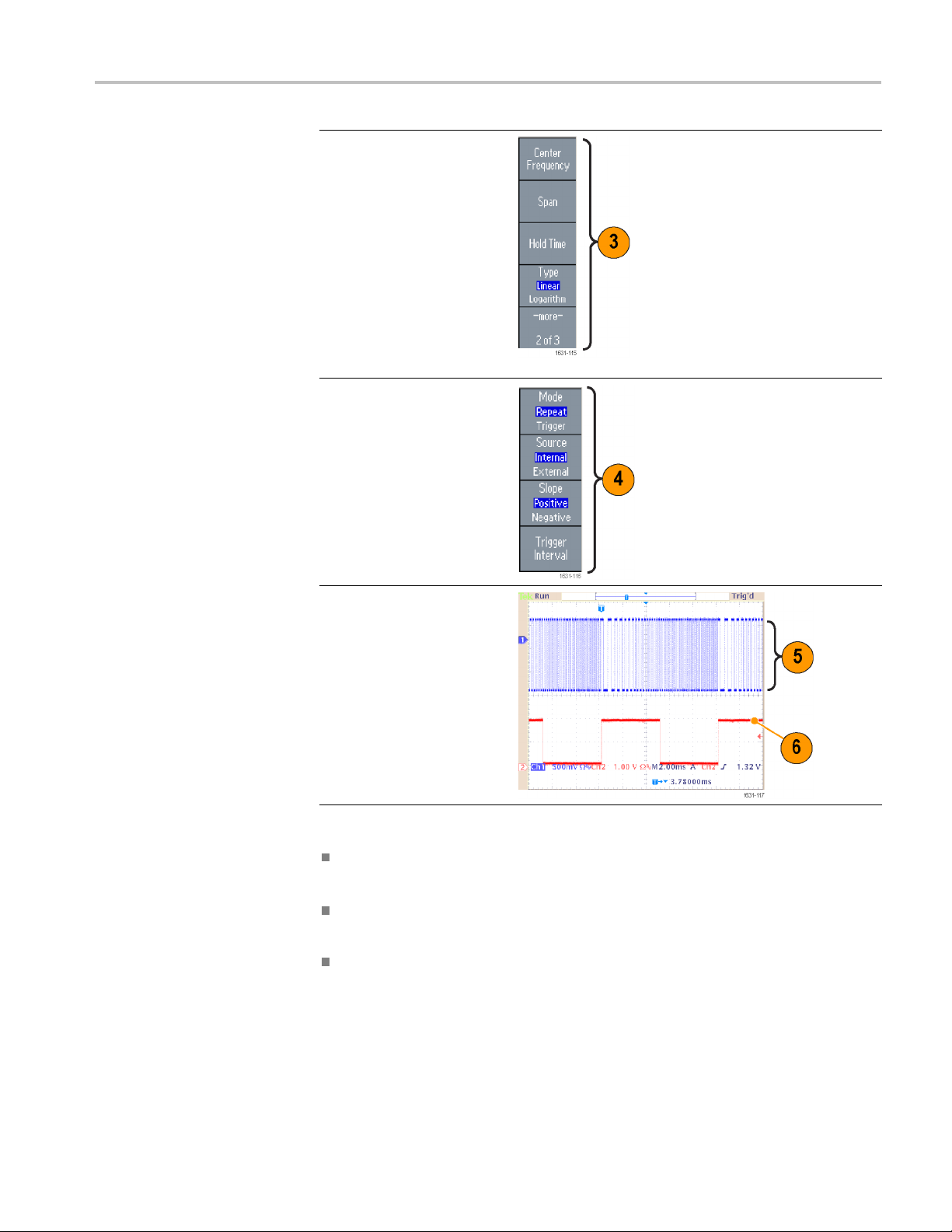
3. In this page, y
the parameters for center
frequency, frequency
span, hold tim
select the sweep type.
Hold time represents the
amount of tim
frequency must remain
stable after reaching the
stop freque
Push the -more- button
to display the second
sweep menu.
4. In this page, you can
select the
(Repeat or Trigger) and
trigger source.
ou can set
e and
e that the
ncy.
sweep mode
Quick Tips
5. This is a sample
oscilloscope screen.
Thetopisasampleofa
sweep waveform.
6. This is a trigger output
signal.
For freque ncy sweep, you can select a sine, square, ramp, or arbitrary
waveform. Pulse, DC, and Noise waveforms cannot be selected.
Once the sweep is selected, the frequency is swept from the sweep start to
the sweep stop frequencies.
If a start frequency is lower than a stop frequency, the instrument sweeps from
the low frequency to the high frequency.
AFG3000 Series Quick Start User Manual 57

Operating basics
Modulate a Waveform
To Output an AM Waveform
If a start frequ
ency is higher than a stop frequency, the instrument sweeps
from the high frequency to the low frequency.
Ifyouwanttor
eturn to the Sweep menu after selecting other menus, push
the front-panel Sweep button again.
1. Select a waveform and then
push the front-panel Modulation
button.
In this example, use sine
waveform as an output waveform
(carrier w
2. Push the top bezel button to
display t
menu.
Select AM as the modulation
type.
aveform).
he modulation selection
58 AFG3000 Series Quick Start User Manual
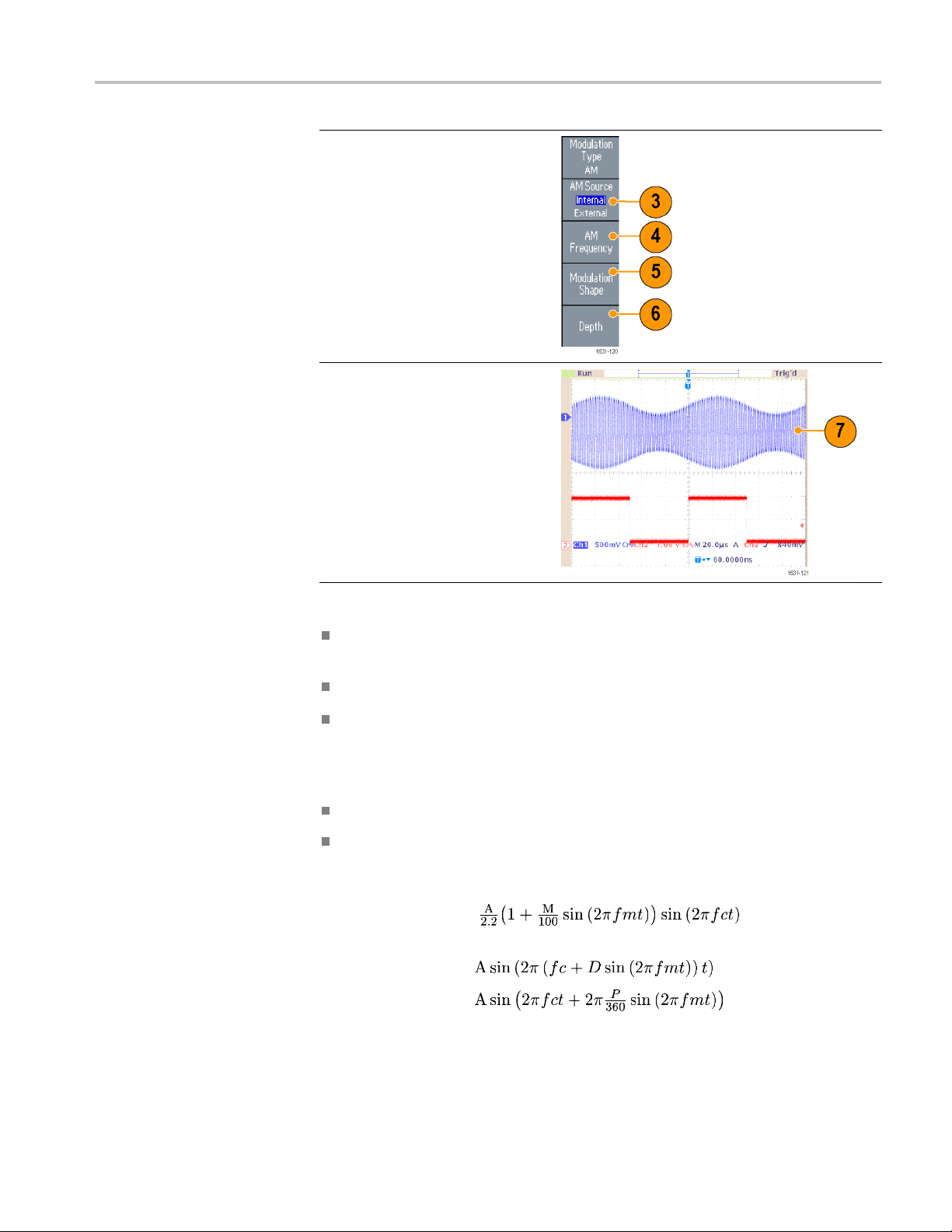
3. Select modulation source.
4. Set m odulation frequency.
5. Select modula
6. Set modulation depth.
7. This is an example amplitude
modulation waveform displayed
on an oscilloscope screen.
tion shape.
Operating basics
Quick Ti
ps
You can o
utput frequency modulation or phase modulation waveforms in the
same way.
You cannot select Pulse, Noise, or DC as a carrier waveform.
You can select an internal or external signal as an AM source. If you select an
external source and set the modulation depth to 120%, the output will be at the
maximum amplitude when a ±1 V
signal is applied to the rear panel EXT
p-p
MODULATION INPUT connector.
You can select a modulation shape from the internal memory or USB flash drive
The following equations show the output amplitude of AM, FM, and PM
modulation (in this example, sine waveform is used for carrier waveform and
modulation waveform):
AM: Output(V
FM: O
utput(V
PM: Output(V
p-p
p-p
p-p
)=
)=
)=
AFG3000 Series Quick Start User Manual 59

Operating basics
Carrier amplitude A [V
]
p-p
Carrier frequency fc [Hz]
Modulation frequency fm [Hz]
Time t [sec]
AM Modulation depth
M[%]
FM Deviation D [Hz]
PM Deviation P [degree]
The following table shows relationship between modulation depth and
maximum amplitude for AM modulatio n waveform (internal modulation
source is selected):
Depth Maximum am plitude
120% A (V
100% A (V
50% A (V
0% A (V
)
p-p
) * 0.909
p-p
) * 0.682
p-p
) * 0.455
p-p
60 AFG3000 Series Quick Start User Manual
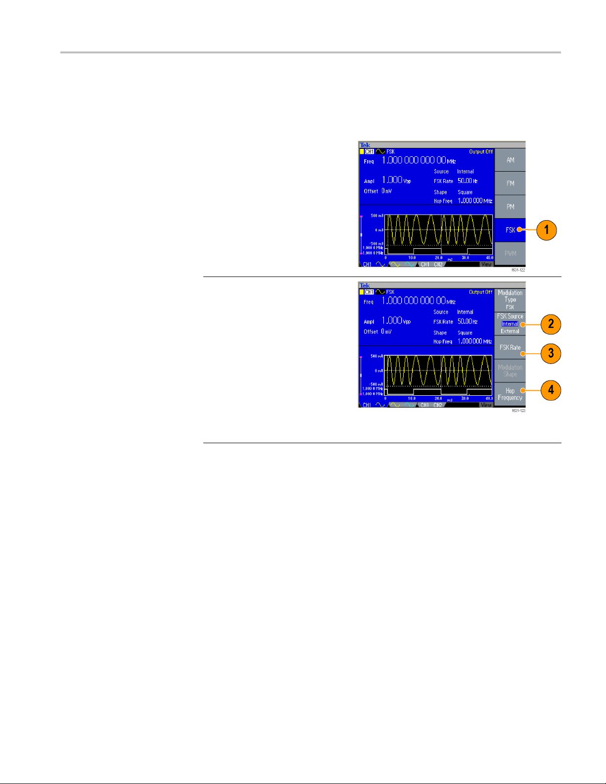
Operating basics
To Output an FSK
Waveform
Frequency Shif
t Keying modulation is a modulation technique that shifts the
output signal frequency between two frequencies: the carrier frequency and Hop
frequency.
1. Follow the steps described
in theToOutp
Waveform procedure to display
the modulation type selection
submenu. (See page 69,
Modulate a Waveform.)
In this example, select FSK as
the modulat
2. The FSK parameter setting
screen is displayed.
Select In
FSK source.
3. If you select Internal, you can set
the FSK R
If you select External, the FSK
Rate is ignored.
4. Set Hop F
Carrier waveform frequency
shifts to the Hop frequency with
cified FSK rate, and then
the spe
returns to the original frequency.
ut an AM
ion type.
ternal or External as
ate.
requency.
AFG3000 Series Quick Start User Manual 61
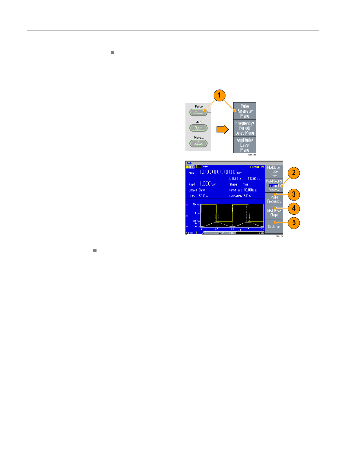
Operating basics
Quick Tip
To Output a PWM
Waveform
The AFG3000 ser
ies instruments generate a phase continuous FSK signal.
Follow these steps to output a PWM waveform.
1. Push the front-panel
Pulse button, and
then push the Pulse
Parameter Menu bezel
button to display the
pulse parameter setting
screen.
2. Push the front-panel
Modulation button
to display
parameter setting screen.
Select the PWM source.
3. Set the PW
4. Select the Modulation
Shape.
5. Set the D
width deviation).
the PWM
M frequency.
eviation (pulse
Quick Tip
See an applicat
ion example of pulse-width modulation. (See page 94, Motor
Speed Control by Pulse-Width Modulation.)
62 AFG3000 Series Quick Start User Manual

Trigger Out
Operating basics
The Trigger Output signal of the instrument is linked to the run mode and
function selected in CH1 if your instrument is a dual-channel model.
1. Connect the
Trigger Output connector
and the external trigger
input conn
oscilloscopes. T he
Trigger Output connector
provides t
for oscilloscopes.
2. Continuous mode: The
trigger output is a square
waveform
edge at the start of each
waveform period.
When an o
frequency is higher
than 4.9 MHz, some
restri
See the Quick Tips below.
3. Sweep mode: When the
Repea
mode and internal trigger
source are selected, the
er output is a square
trigg
waveform and the rising
edge at the start of each
swee
front-panel
ector of the
he trigger signal
and the rising
utput
ctions are applied.
t or Trigger sweep
p.
AFG3000 Series Quick Start User Manual 63

Operating basics
4. Modulation mo
an internal modulation
source is selected,
the trigger ou
square waveform of the
same frequency as the
modulating s
When an external
modulation source is
selected, t
output is disabled.
5. Burst Mode: When
an internal trigger source
is selected, the trigger
output is a square
waveform and the rising
edge at the start of each
burst period.
When an external trigger
source is selected, the
trigger output is high
during the time the trigger
input is high.
de: When
tput is a
ignal.
he trigger
64 AFG3000 Series Quick Start User Manual

Operating basics
Quick Tips
When a setting f
requency of an output waveform is higher than 4.9 MHz, a
divided frequency that is lower than 4.9 MHz is output from the Trigger Out.
Seethetablebelow:
Set frequenc
〜4.900 000 000 00 Fs
4.900 000 000 01 to 14.700 000 000 0
14.700 000 000 1 to 24.500 000 000 0
24.500 000 000 1 to 34.300 000 000 0
34.300 000 000 1 to 44.100 000 000 0
44.100 000 000 1 to 50.000 000 000 0
50.000 000 000 1 〜 No signal
y of output waveform (MHz)
Trigger outp
Fs/3
Fs/5
Fs/7
Fs/9
Fs/11
ut frequency (MHz)
NOTE. The Trigger Out signal cannot be output when the instrument outputs a
uous signal higher than 50 MHz.
contin
NOTE. When the instrument outputs a modulation waveform, Trigger Output
l cannot be output if you select External as the modulation source.
signa
Adjusting parameters of two channel signals (dual-channel models only)
Phase
The AFG3000 series uses phase continuous method to change frequency. When
you change the frequency of a ch
annel, it will affect the phase relationship
between the two channels.
For example, the instrument is generating a 5 MHz sine waveform for both CH1
and CH2 and the phase is adjusted between the two channels. If you change the
CH2 frequency to 10 MHz and
t return to its initial condition. To adjust the phase relationship between the
o
n
then return it to 5 MHz, the CH2 phase does
twochannels, youneedtostopsignalgeneration and restart it. The instrument
provides a function called " Align Ph
ase" to adjust the phase relationship.
AFG3000 Series Quick Start User Manual 65
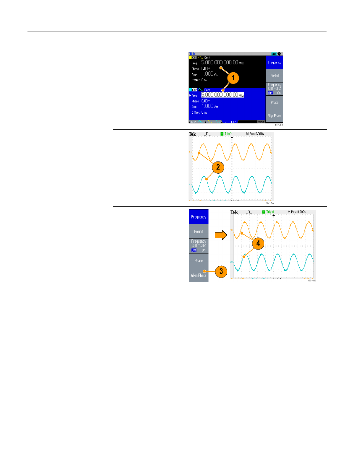
Operating basics
1. In this example
5 MHz continuous
sine waveform is used.
Confirm that bo
are set to 0 degrees.
2. Change the C
frequency to 10 MHz,
and then back to 5 MHz.
In this sta
phase does not return to
its initial condition.
3. To ali gn t
channel signals, push the
Align Phase bezel button.
4. When you
Align Phase button,
the instrument will stop
the sig
adjust the phases of
both channels, and
automa
signal generation.
te, the CH2
he phase of two
push the
nal generation,
tically restart the
,a
th phases
H1
66 AFG3000 Series Quick Start User Manual
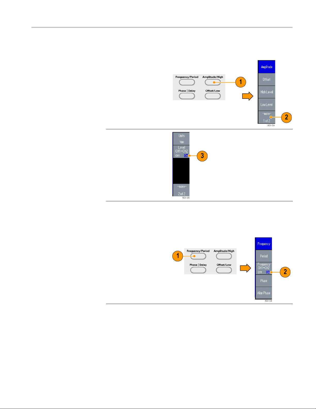
Operating basics
Amplitude
To set the CH1 am
1. Push the front-panel
Amplitude/Hi
button.
2. Push the -more- bezel
button.
3. Page two of
Amplitude/Level Menu is
displayed.
You can set the CH1 and
CH2 amplitude to the
same level by selecting
On in the second bezel
menu from the top.
plitude and CH2 amplitude to the same level, follow these steps:
gh shortcut
Frequency (Period)
To set the CH1 frequency and CH2 frequency to the same value, follow these
steps:
1. Push th
2. You can set the CH1 and
e front-panel
Frequency/Period
shortcut button to display
quency/Period
the Fre
Parameter Menu.
equency to the
CH2 fr
same value by selecting
On in the third bezel
rom the top.
menu f
AFG3000 Series Quick Start User Manual 67
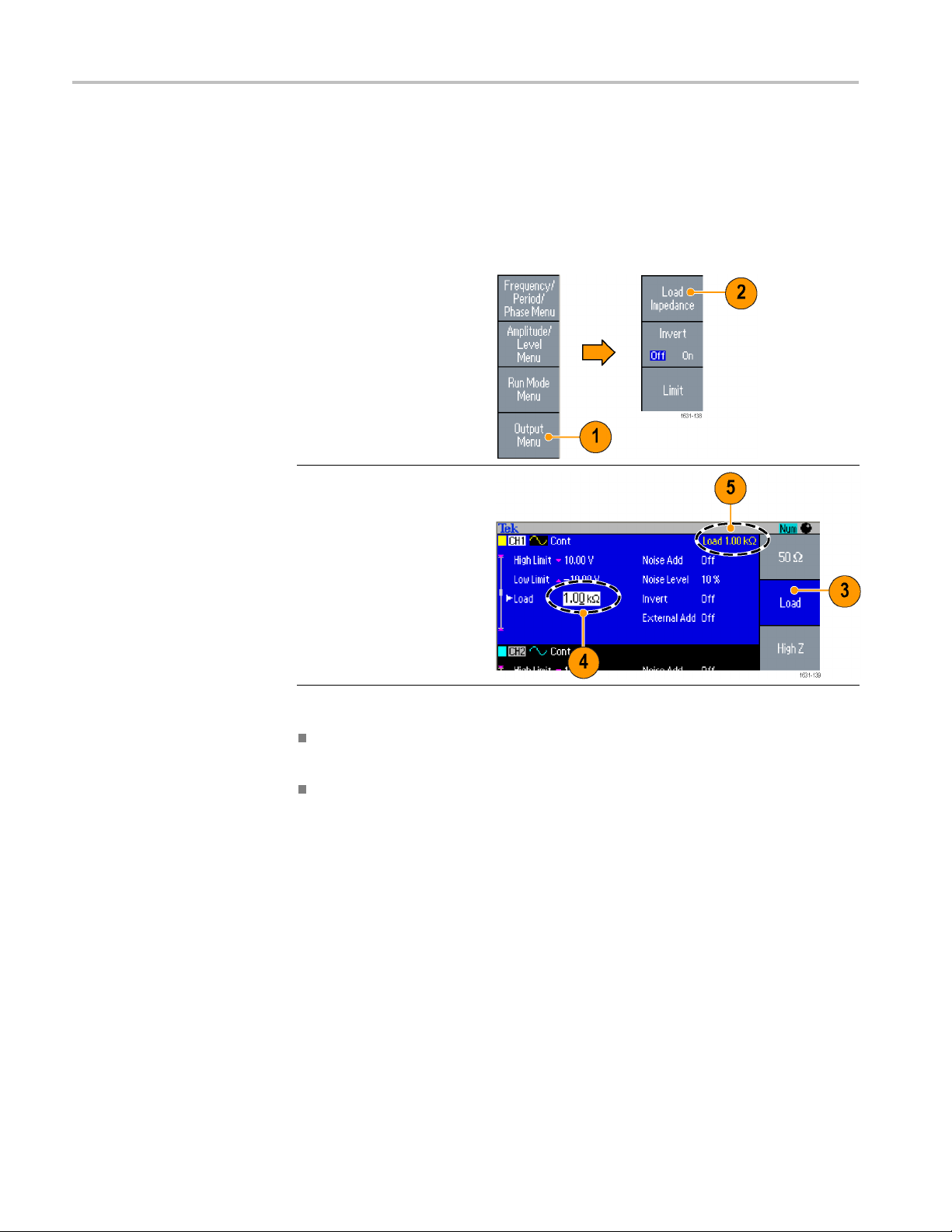
Operating basics
SetupLoadImp
edance
The output impedance of the AFG3000 series is 50 Ω. If you connect a load other
than 50 Ω, the displayed Amplitude, Offset, and High/Low values are different
from the outp
ut voltage. To make the displayed v alues same as output voltage,
you need to set load impedance. To set the load impedance, use the Output menu.
1. Push the front-panel Top
Menu button, and then
push the Output Menu
bezel button. The Output
Menu is displayed.
2. Push Load Impedance
to display the Load
Impedance submenu.
3. To adjust the load
impedance, select Load.
4. You can set the load
impedance to any value
from 1 Ω to 10 kΩ.
5. When the load
impedance is set to
other than 50 Ω,theset
value is displayed in the
output status.
Quick
Tips
The load impedance is applied to the amplitude, offset, and high/low level
settings.
When dBm is specified for output amplitude units, the amplitude units setting
is automatically changed to Vpp if you select high impedance.
68 AFG3000 Series Quick Start User Manual

Operating basics
Invert Wavefo
rm Polarity
To invert a waveform polarity, use the Output menu. The following example
shows how to get a differential signal u sing the invert function of dual channel
model:
1. Select the CH1
2. Push the front-panel
3. Push the Fr
4. Select the
5. Push the front-panel
6. Push the Output Menu
waveform.
Frequency/Period button.
equency
bezel button to set the
CH1 frequency.
third bezel
button from the top to
set the two channel
frequenc
value.
Channel Select button to
select C
> Invert bezel buttons to
invert
ies to the same
H2.
the CH2 waveform.
7. Push the front-panel
CH1 Output On button to
le the output.
enab
8. You can get a differential
signal.
AFG3000 Series Quick Start User Manual 69

Operating basics
Add Noise
To add the internal noise signal to a waveform, use the Output menu.
1. Push the front
Sine > Continuous
buttons to display the
Sine waveform screen in
this example.
2. Follow the steps
described in the previous
pages to display the
Output Menu. (See
page 80.) To add noise
to a sine waveform, push
Noise.
3. The Noise Add submenu
is displayed. Push Noise
Add to select On.
4. To adjust the noise level,
push Noi
the general purpose
knob or the numeric pad
to enter
5. This is a waveform before
adding noise.
6. This is a waveform after
adding noise.
To avoid overflow by
noise addition, the
amplitude of the output
signal is automatically
halved.
-panel
se Level. Use
the value.
70 AFG3000 Series Quick Start User Manual

Operating basics
Quick Tips
An internal noi
se generator (digital) is used to add noise.
CH1 and CH2 noise signals are non-correlating.
The Output Status is changed from Output Off to Noise when you push the
front-panel Channel Output button to enable the output.
NOTE. When y
ou set Noise Add to On, the amplitude of output signal is reduced
to 50%.
Add signal (AFG3100 and AFG3200 Series)
The AFG3101 / 3101C / 3102 / 3102C and AFG3251 / 3251C / 3252 / 3252C rear
panel ADD INPUT connector allows you to add an external signal to the CH1
output signal.
1. Connect an external
signal source to the
nel ADD INPUT
rear pa
connector.
2. Push the front-panel Top
Menu button, and then
he Output Menu
push t
bezel button.
3. Push External Add to
ct On.
sele
AFG3000 Series Quick Start User Manual 71

Operating basics
4. The following is an
example of adding noise
as an external
The upper waveform is
an external signal.
5. The bottom wa
square waveform before
adding external signal.
6. This is an example of
square waveform after
adding ext
(noise).
signal.
veform is a
ernal signal
Quick Tip
The Output Status is changed from Output Off to Ext Add when you push the
front-panel CH1 Output button to enable the output.
Generating a Differential Signal
A dual-ch annel instrument can be used to generate a differential signal by
programming CH2 to output the complement of CH1. The CH2 settings can be
configured conveniently by using the CH1 Complement function.
72 AFG3000 Series Quick Start User Manual

1. After setting the CH1
waveform parameters,
push the front
Channel select button to
select CH2.
-panel
Operating basics
2. Push the fr
Menu button, and then
push the Output Menu
bezel butt
3. Push the CH1
Complement bezel
button.
4. The CH2 wave shape
and timing parameters
are copi
and the CH2 amplitude
settings are inverted from
CH1.
ont-panel Top
on.
ed from CH1,
NOTE. When CH1 is selected in the AFG310x or AFG325x series instrument, the
instrument displays External Add Off/On in the Output menu.
AFG3000 Series Quick Start User Manual 73

Operating basics
External Refe
rence Clock
1. The external reference
input (EXT REF INPUT)
and the external
reference output
(EXT REF OUTPUT)
connectors are provided
on the AFG3000 series
rear panel.
2. The instrument can use
the internal or external
signal as a reference
signal.
To select a reference
signal, push the
front-panel Utility button
and then push the
System bezel button.
3. Push the Clock Ref bezel
menu button to toggle
between Internal and
External.
Quick Tips
The external reference Input and Output connectors are used for synchronizing
ple AFG3000 series instruments.
multi
The instrument can use the internal source or an external sou r ce as a reference
al. When the internal reference is activated, a 10 MHz reference signal
sign
is output on the rear panel EXT REF OUT connector. This output signal
synchronizes other devices to the instrument.
When the external reference input is activated, the rear panel EXT REF
INPUT connector is used as the input for an external reference signal. The
instrument is synchronized by this external reference signal.
The EXT REF OUTPUT connector is not provided on the AFG3021,
AFG3022, AFG3051, or AFG3052.
74 AFG3000 Series Quick Start User Manual

Operating basics
Synchronous O
peration
To synchronize multiple arbitrary function generators, use the Utility menu.
Some documentation may also refer to the synchronous operation as master-slave
operation.
1. Use a BNC cable to
connect the
Trigger Output of one
instrument (master) to the
Trigger In
unit (slave).
The master unit sends a
trigger si
unit.
2. Connect the rear panel
EXT REF OU
and EXT REF IN (slave)
with another BNC cable.
The mast
the slave clock are
synchronized.
3. Push the front-panel
Utilit
master unit to display the
System menu.
4. Sets th
front-panel
put of another
gnal to the slave
T(master)
er clock and
y button of the
e following:
er Out - Sync
Trigg
Ref - Internal
Clock
5. Set the slave instrument:
Display the System
menu, and then push the
Clock Ref bezel button to
select External.
AFG3000 Series Quick Start User Manual 75

Operating basics
6. Select Burst as the Run
Mode for both the master
and the slave i
To synchronize two
instruments, you must
stop running
signals once before
triggering using the B urst
mode.
7. Select the t
of the slave unit.
Push the -more- bezel
button in t
to display the second
page.
8. Push the S
button to select External.
Confirm that Internal is
selected
and External is selected
in the slave for Source.
nstrument.
output
rigger source
he Burst mode
ource bezel
in the master
9. This screen shows signal
outputs by master-slave
operation. The top
waveform is the signal of
the master unit.
10. When one meter long
cables are used, the
slave signal delay
approximately 40 ns.
11. To make the delay
between the master and
slave 0 (zero), set the
Delay of the master unit.
12. The screen shows
waveforms after setting
the delay to the master
unit. The top waveform
is master and the two
bottom waveforms are
slaves.
76 AFG3000 Series Quick Start User Manual

Operating basics
Quick Tip
USB flash drive
To output conti
as the trigger source for the master unit to stop signal generation. Select
Inf-Cycles as the burst count for both master and slave units. Change the
trigger source of the master unit to Internal to restart the signal generation.
A USB flash drive connector is provided with all the Tek
Series Arbitrary Function Generators to allow you to perform the following
tasks:
e or recall user-defined waveforms to or from a USB flash drive,
Sav
Save or recall setups to or from files on a USB flash drive,
Update your instrument firmware,
Save a screen image,
CAUTION. When you attach a USB flash drive to the instrument, a caution
message appears on the screen. Do not remove the USB flash drive until the
message disappears.
If you remove the USB flash drive while this caution message is displayed, it
may cause damage to the instrument.
nuous waveforms by synchronous operation, select External
tronix AFG3000
Qui
Read more about saving/recalling user-defined waveforms. (See page 47,
Save/Recall Arbitrary Waveforms.). Read more about saving/recalling instrument
setups. (Seepage80,Save/Recall Instrument Setup.). Read more about updating
your instrument. (See page 15, Update your instrument firmware.)
ck Tips
NOTE. Emissions may exceed the specification limit if a USB cable is placed in the
front-panel USB flash drive
Use a USB flash drive with cross section smaller than 20 mm x 12
mm to connect to the AFG3000 series front-panel USB connector. To
connect a larger USB flash drive, use an extension cable.
The AFG3000 series instruments support USB flash drives with a
FAT12, FAT16, or FAT32 file systems.
connector. Use only appropriate USB flash drive devices.
AFG3000 Series Quick Start User Manual 77

Operating basics
Utility Menu
Push the front-panel Utility button to display the Utility menu. The Utility menu
provides access to utilities used by the instrument such as I/O interface, system
related menus, diagnostics/calibration, and local language preferences.
1. Push the front-panel
Utility button to display
the Utility menu.
2. I/O interface. (See page
17.)
3. Language selection. (See
page 10.)
4. For "System related
menus. (See page 78
steps 6 and 10.)"
5. Push the Status bezel
button to display the
instrument status.
Push the System bezel
button to d isplay the System
submenu
6. Trigger Out. (See page
7. Reference Clock. (See
8. You can select the
9. Executing the Secure
10. Push the -more- button to
11. Pus
12. Pus
13. Push Beeper to toggle the
.
63.)
page 74.)
instrument power-on
settings.
function will erase all data
except the MAC Address,
calibration data, and the
instrument serial number.
lay the second page.
disp
Push Contrast to adjust
the screen contrast.
h Screen Saver to
toggle the screen saver
Off and On.
h Click Tone to toggle
the click tone Off and On.
ep sound Off and On.
be
78 AFG3000 Series Quick Start User Manual

Operating basics
14. Push the previ
arrow button located
beneath the bezel buttons
to return to th
menu. Push the -morebutton to display the
second page.
15. For Backup/Restore, see
step 17.
16. You can copy
waveform parameter
of one channel to another
channel.
17. Push the Ba
bezel button to display
the Backup/Restore
submenu.
In this menu, you can
back up a waveform data
from internal memory to a
USB flash drive or
restore a waveform data
from a USB flash drive to
internal memory.
ous menu
e previous
the
ckup/Restore
18. Return to the Utility main
menu. Push the -morebezel button to display
the third page. On this
page, you can execute
the instrument firmware
update. (See page 15,
Update your instrument
firmware.)
19. Security Menu. (See
page 81, Using the
Security Menu.).
AFG3000 Series Quick Start User Manual 79

Operating basics
Save/Recall I
nstrument Setup
You can save setups of the instrument as files in the internal memory or in an
external
internal memory or in a USB flash drive.
1. Push the front-panel
Save button
the Save Menu.
2. To specify a memory
location,
or USB. In this example,
select USB.
Use the gen
knob to scroll files. Push
Save to save a setting.
3. You can save a setup as
a new file i
USB. Push Save As.
4. You can enter a fi le name
in this s
general purpose knob to
select a character. Push
the Ent
button or the front-panel
Enter key to enter the
charac
5. To recall a setup, push
the fr
button.
6. Select a memory location
(Inte
then push the Recall
bezel button.
USB flash drive You can recall the stored setups from a file in the
to display
select Internal
eral purpose
f you specify
creen. Use the
er Character bezel
ter.
ont-panel Recall
rnal or USB), and
Quick Tips
You can lock a setup file to avoid accidental overwrite. When a memory
location is locked, a lock key icon will appear on the screen. To lock or unlock
tup file, push the Lock/Unlock bezel button.
ase
To erase a file, push the Erase bezel button.
Output state is Off by default after reading a setup file.
IfyousaveasetuptoaUSB flash drive, afile with the extension TFS is
saved.
80 AFG3000 Series Quick Start User Manual
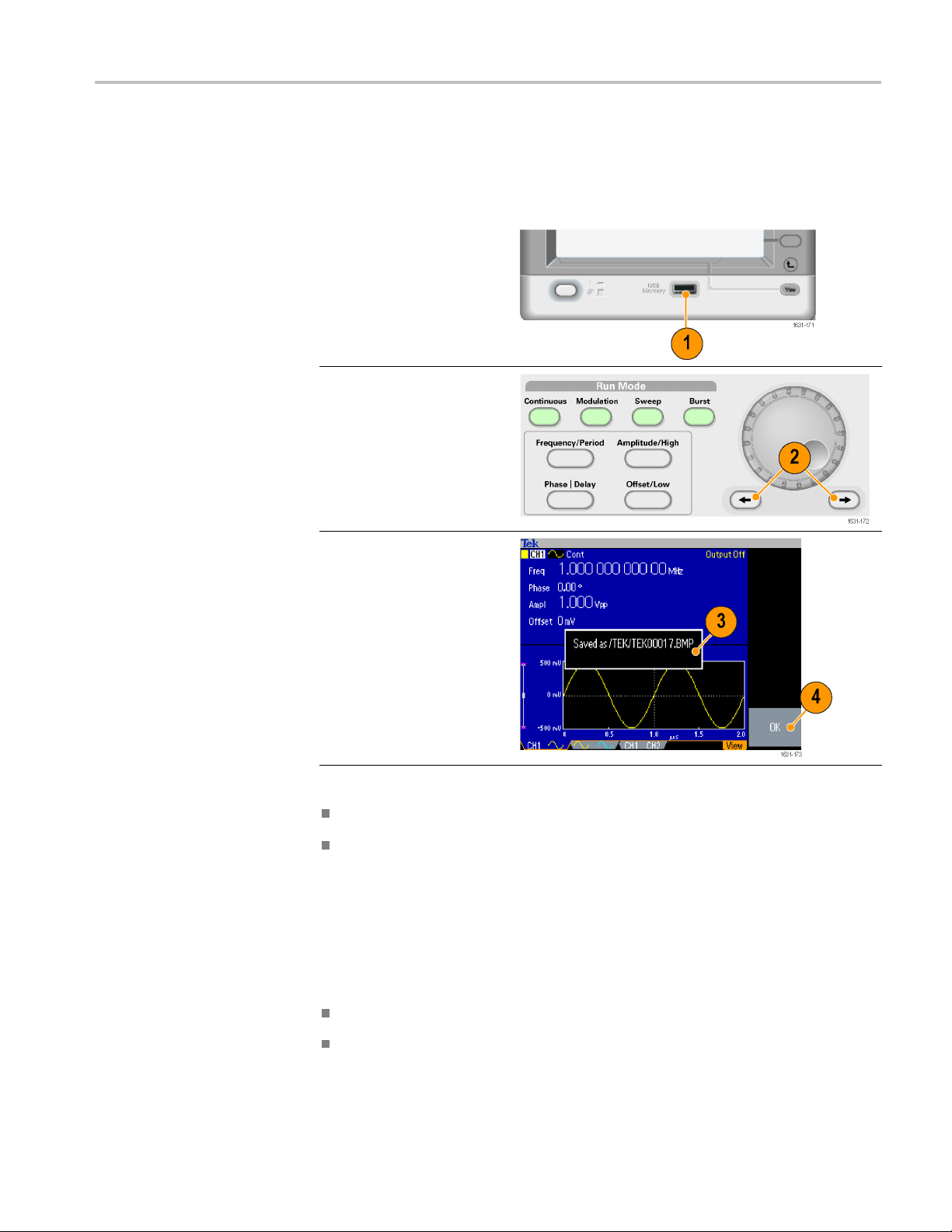
Operating basics
Saving a Scree
nImage
You can save a screen image of the
the following steps:
1. Insert a USB flash drive
to the front-panel USB
connector.
2. Set the display to show
the screen you want to
save as an image.
Then simultaneously
push the two arrow
keys underneath the
rotary knob on the front
panel.
3. A message appears on
the screen, indicating that
the screen image was
saved.
4. Push OK.
instrument to a USB flash drive Do
Quick Tips
Image files are saved in a folder named "TEK" on the USB flash drive.
Image files are saved as .BMP format. The instrument gives all files created
by the instrument the default name TEK00nnn.BMP, where nnn is a
placeholder for an automatic number sequence from 000 to 999.
Using the Security Menu
Use the Security menu to limit access to the following menus:
Firmware update
Service menu (refer to the service manual for information about the service
menu).
AFG3000 Series Quick Start User Manual 81

Operating basics
Access Protection
The access prot
ection is set to Off by default. To turn the access protection on,
do the following steps:
1. Push the front-panel
Utility button to display
the Utility menu, and then
push the -more- bezel
button twice.
2. Select Security Menu.
3. Select Acc
to display the password
input page.
4. Enter you
Use the general purpose
knob to select the
charact
the Enter Character
bezel button after each
selecti
As you enter the
characters of your
passwo
displayed as a series of
asterisks (*******) on the
passw
If no specific password
has been previously
define
password DEFAULT.
5. Select OK to turn the
acce
ess Protection
r password.
ers and push
on.
rd, they are
ord input page.
d, use the default
ss protection on.
NOTE. When Access Protection is on, the Change Password bezel button is
disabled.
82 AFG300
0 Series Quick Start User Manual
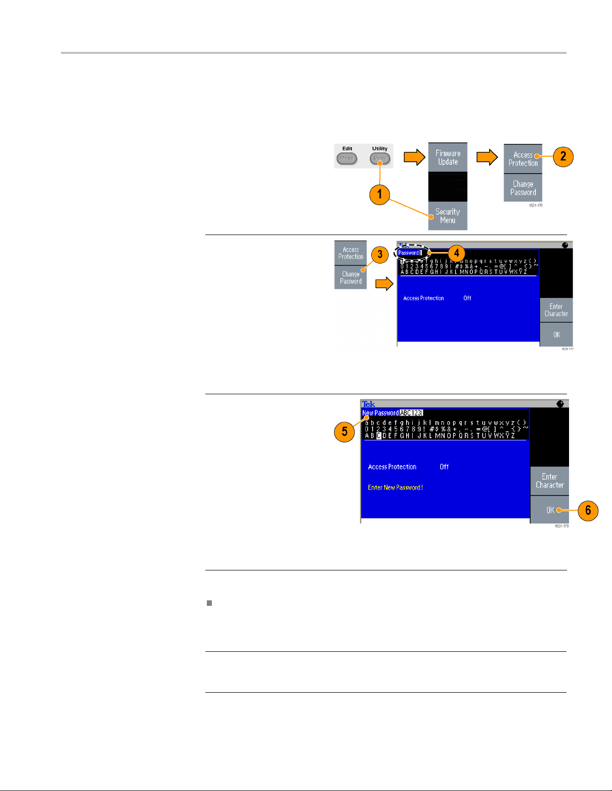
Changing the password
1. Select Security Menu
2. If the Access P
3. Select Change Password
4. Enter your current
5. Enter a new password.
6. Select OK to activate the
Operating basics
fore the password is changed for the first time, the default password is
Be
DEFAULT. To change the password, do the following steps:
from the Utility menu.
rotection is
set to On, turn it off using
the Access Protection
menu. Otherw
step 3.
to display the password
input page.
password.
Use the general purpose
knob to s e lect the
characters and push
the Enter Character
bezel button after each
selection. Then select
OK to display the New
Password input page.
As you enter the
characters of your new
password, they are
displayed on the screen.
Check carefully to ensure
you are entering the
desired characters.
new password.
ise, skip to
NOTE. A password must
have at least four characters,
and not more than12
characters.
Quic
kTip
Use the front-panel general purpose knob to select a character when you enter
a password, and then push the Enter Character bezel button. You can also use
the front-panel numeric keypad and the Enter button.
E. To activate or deactivate the access protection, you must enter the
NOT
password you set. If you forget the password, you must return the instrument to
Tektronix to reset the password.
AFG3000 Series Quick Start User Manual 83

Operating basics
ArbExpress
ArbExpress is a Windows-based software for creating and editing waveforms for
Tektronix AWG and AFG instruments. With ArbExpress, you can quickly and
conveniently create the desired waveforms and send them to the instrument.
The following table and list describe the system requirements and general features.
System requirements
OS Supported Windows XP Professional or Windows
2000 or Windows 98/Me or Windows NT or
Windows 7 (32-bit only)
Minimum PC Requirements
TekV ISA
Pentium III 800 MHz and higher 256 MB
RAM 300 MB free hard disk Microsoft
Internet Explorer 5.01 and higher .NET
Framework 1.1 Redistributable 800 x 600
Display resolution
Version 3.3.4.6 and above
Create
waveforms from standard waveform templates
Modify and transfer waveforms to perform DUT level tests
Directly import waveforms from Tektronix oscilloscopes
Send waveforms to AWG/AFG instruments directly from ArbExpress or
MATLAB
Math operations on waveforms
NOTE. You
can use ArbExpress to transfer waveform data to the instrument.
When you transfer waveform data (.tfw file), any part of the waveform outside
llowed limits in the AFG3000 series will be automatically converted to be
of a
within the allowed range.
e following pages contain the screen interface and basic operating procedures
Th
for using ArbExpress. For more information on ArbExpress, refer to the
ArbExpress online help.
84 AFG3000 Series Quick Start User Manual

Operating basics
Screen interfa
ce
Item Description
1
2
3
4
5
6
Menu bar: The menu bar provides access to the application functions. When
you select a menu item, the application displays the associated dialog box or the
election causes an immediate action.
menu s
ar: The toolbar buttons provide instant access to most features without
Toolb
having to navigate through several menus.
Waveform display area:
displayed in this area.
Marker area: Marker patterns appear in this area. You can toggle the display of
rkers by selecting Display > Marker from the menu bar.
ma
tus bar: The status bar, located below the waveform and marker display,
Sta
shows information about the application and the waveform.
Shortcut View: The Shortcut view occupies the left part of the display. Use
the Shortcut view to quickly access various functions provided by the
application. Refer to the ArbExpress online help for more information.
When you create or open a waveform, it will be
AFG3000 Series Quick Start User Manual 85

Operating basics
Basic operations
The following s
that are available with ArbExpress.
1. To create a new waveform, use the File menu.
2. Blank sheet opens a blank sheet in the window
with a 1024 point waveform length. You can
change the number of points using Properties...
from the Waveform menu.
3. Use the Sta
create any of the standard waveforms that are
available. Use Settings to select a desired
waveform a
4. Use Vertical to set the waveform vertical
parameters.
5. Use Horiz
parameters.
6. Click Preview to view the waveform.
ndard Waveform d ialog box to
nd instrument type.
ontal to set the waveform horizontal
teps explain basic waveform creation and other useful functions
7. You can also use the Equation Editor to create
orm. The application provides a set of
a wavef
sample equations that you can directly use or
modify.
8. Use Com
functions, units, and operations.
9. Use Preview to view the waveform after the
equat
mand List to select the commands,
ion is compiled.
86 AFG3000 Series Quick Start User Manual
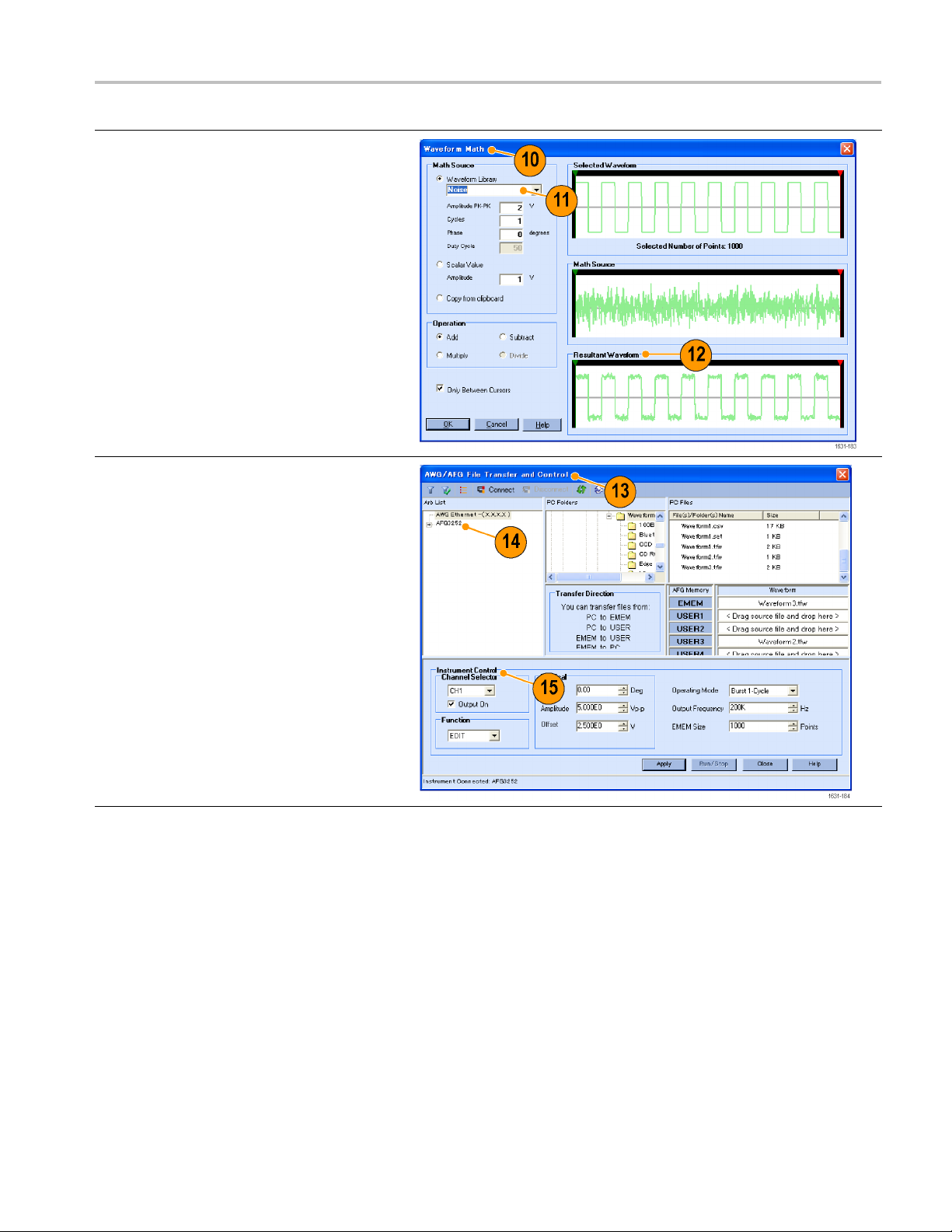
10. You can also use a waveform math tool.
From the Math menu, select Waveform Math...
to display the
11. Select a math source from Waveform Library.
Select Noise in this example.
12. Calculation
Resultant Waveform pane. This is an example
of adding noise to a square waveform.
13. You can remotely control Tektronix AWG/AFG
instruments using ArbExpress.
From the Communication menu, select
AWG/AFG File Transfer & Control... to display
thedialogbox.
14. Connected instruments are listed on the Arb
List.
15. The Instrument Control pane appears only
when an instrument is connected, otherwise it
is hidden.
Waveform Math dialog box.
results are displayed in the
Operating basics
AFG3000 Series Quick Start User Manual 87

Operating basics
Using CSV format
waveform data
ArbExpress all
which is created by Microsoft Excel, to waveform data that is compatible with
the instrument.
1. Create a CSV fi
2. Enter point or time to this column.
3. Enter data to this column.
When you ope
appear to confirm the CSV file format.
4. This is an example of A rbExpress waveform
display area after recalling CSV data.
le to use with ArbExpress.
naCSVfile, a dialog box may
ows you to convert a CSV (Comma Separated Value) format file,
88 AFG3000 Series Quick Start User Manual
 Loading...