

Page 1

Reference Manual
AFG3000 Series
Arbitrary/Function Generators
071-1639-03
This document supports firmware version 2.0.0 and above.
www.tektronix.com
Page 2

Copyright © Tektronix. All rights reserved. Licensed software products are owned by Tektronix or its subsidiaries or
suppliers, and are protected by national copyright laws and international treaty provisions.
Tektronix products are covered by U.S. and foreign patents, issued and pending. Information in this publication
supercedes that in all previously published material. Specifications and price change privileges reserved.
TEKTRONIX and TEK are registered trademarks of Tektronix, Inc.
Contacting Tektronix
Tektronix, Inc.
14200 SW Karl Braun Drive or P.O. Box 500
Beaverton, OR 97077 USA
For product information, sales, service, and technical support:
In North America, call 1-800-833-9200
Worldwide, visit www.tektronix.com to find contacts in your area.
Page 3

WARRANTY 16
Tektronix warrants that the product will be free from defects in materials and workmanship for a period of three (3)
years from the date of original purchase from an authorized Tektronix distributor. If the product proves defective
during this warranty period, Tektronix, at its option, either will repair the defective product without charge for parts
and labor, or will provide a replacement in exchange for the defective product. Batteries are excluded from this
warranty. Parts, modules and replacement products used by Tektronix for warranty work may be new or reconditioned
to like new performance. All replaced parts, modules and products become the property of Tektronix.
In order to obtain service under this warranty, Customer must notify Tektronix of the defect before the expiration of
the warranty period and make suitable arrangements for the performance of service. Customer shall be responsible for
packaging and shipping the defective product to the service center designated by Tektronix, shipping charges prepaid,
and with a copy of customer proof of purchase. Tektronix shall pay for the return of the product to Customer if the
shipment is to a location within the country in which the Tektronix service center is located. Customer shall be
responsible for paying all shipping charges, duties, taxes, and any other charges for products returned to any other
locations.
This warranty shall not apply to any defect, failure or damage caused by improper use or improper or inadequate
maintenance and care. Tektronix shall not be obligated to furnish service under this warranty a) to repair damage
resulting from attempts by personnel other than Tektronix representatives to install, repair or service the product; b) to
repair damage resulting from improper use or connection to incompatible equipment; c) to repair any damage or
malfunction caused by the use of non-Tektronix supplies; or d) to service a product that has been modified or integrated
with other products when the effect of such modification or integration increases the time or difficulty of servicing the
product.
THIS WARRANTY IS GIVEN BY TEKTRONIX WITH RESPECT TO THE PRODUCT IN LIEU OF ANY
OTHER WARRANTIES, EXPRESS OR IMPLIED. TEKTRONIX AND ITS VENDORS DISCLAIM ANY
IMPLIED WARRANTIES OF MERCHANTABILITY OR FITNESS FOR A PARTICULAR PURPOSE.
TEKTRONIX' RESPONSIBILITY TO REPAIR OR REPLACE DEFECTIVE PRODUCTS IS THE SOLE
AND EXCLUSIVE REMEDY PROVIDED TO THE CUSTOMER FOR BREACH OF THIS WARRANTY.
TEKTRONIX AND ITS VENDORS WILL NOT BE LIABLE FOR ANY INDIRECT, SPECIAL,
INCIDENTAL, OR CONSEQUENTIAL DAMAGES IRRESPECTIVE OF WHETHER TEKTRONIX OR
THE VENDOR HAS ADVANCE NOTICE OF THE POSSIBILITY OF SUCH DAMAGES.
Page 4

Page 5

Table of Contents
Operating Basics
Reference
Syntax and Commands
General Safety Summary . . . . . . . . . . . . . . . . . . . . . . . . . . . . . . . . . . . . . . . . . . . . . . ix
Preface . . . . . . . . . . . . . . . . . . . . . . . . . . . . . . . . . . . . . . . . . . . . . . . . . . . . . . . . . . . . . xi
Documentation . . . . . . . . . . . . . . . . . . . . . . . . . . . . . . . . . . . . . . . . . . . . . . . . . . . . . . . . xii
Operating Basics . . . . . . . . . . . . . . . . . . . . . . . . . . . . . . . . . . . . . . . . . . . . . . . . . . . . 1-1
Front Panel Controls . . . . . . . . . . . . . . . . . . . . . . . . . . . . . . . . . . . . . . . . . . . . . . . . . . 1-2
Display Area and Screen Interface. . . . . . . . . . . . . . . . . . . . . . . . . . . . . . . . . . . . . . . 1-11
Waveform Parameters and Numeric Input . . . . . . . . . . . . . . . . . . . . . . . . . . . . . . . . . 1-14
Rear Panel . . . . . . . . . . . . . . . . . . . . . . . . . . . . . . . . . . . . . . . . . . . . . . . . . . . . . . . . . 1-19
Reference . . . . . . . . . . . . . . . . . . . . . . . . . . . . . . . . . . . . . . . . . . . . . . . . . . . . . . . . . . 2-1
Menu System . . . . . . . . . . . . . . . . . . . . . . . . . . . . . . . . . . . . . . . . . . . . . . . . . . . . . . . . 2-1
Menu Structure. . . . . . . . . . . . . . . . . . . . . . . . . . . . . . . . . . . . . . . . . . . . . . . . . . . . . . . 2-2
File Operations. . . . . . . . . . . . . . . . . . . . . . . . . . . . . . . . . . . . . . . . . . . . . . . . . . . . . . 2-30
Syntax and Commands . . . . . . . . . . . . . . . . . . . . . . . . . . . . . . . . . . . . . . . . . . . . . . . 3-1
Command Syntax. . . . . . . . . . . . . . . . . . . . . . . . . . . . . . . . . . . . . . . . . . . . . . . . . . . . . 3-1
Command Groups . . . . . . . . . . . . . . . . . . . . . . . . . . . . . . . . . . . . . . . . . . . . . . . . . . . . 3-9
Command Descriptions . . . . . . . . . . . . . . . . . . . . . . . . . . . . . . . . . . . . . . . . . . . . . . . 3-15
ABORt (No Query Form) . . . . . . . . . . . . . . . . . . . . . . . . . . . . . . . . . . . . . . . . . . . . . 3-15
AFGControl:CSCopy (No Query Form) . . . . . . . . . . . . . . . . . . . . . . . . . . . . . . . . . . 3-16
*CAL? . . . . . . . . . . . . . . . . . . . . . . . . . . . . . . . . . . . . . . . . . . . . . . . . . . . . . . . . . . . . 3-16
CALibration[:ALL] . . . . . . . . . . . . . . . . . . . . . . . . . . . . . . . . . . . . . . . . . . . . . . . . . . 3-17
*CLS (No Query Form) . . . . . . . . . . . . . . . . . . . . . . . . . . . . . . . . . . . . . . . . . . . . . . . 3-17
DIAGnostic[:ALL]. . . . . . . . . . . . . . . . . . . . . . . . . . . . . . . . . . . . . . . . . . . . . . . . . . . 3-18
DISPlay:CONTrast . . . . . . . . . . . . . . . . . . . . . . . . . . . . . . . . . . . . . . . . . . . . . . . . . . 3-19
DISPlay:SAVer:IMMediate (No Query Form). . . . . . . . . . . . . . . . . . . . . . . . . . . . . . 3-19
DISPlay:SAVer[:STATe] . . . . . . . . . . . . . . . . . . . . . . . . . . . . . . . . . . . . . . . . . . . . . . 3-20
DISPlay[:WINDow]:TEXT[:DATA]. . . . . . . . . . . . . . . . . . . . . . . . . . . . . . . . . . . . . 3-21
DISPlay[:WINDow]:TEXT:CLEar (No Query Form) . . . . . . . . . . . . . . . . . . . . . . . 3-21
*ESE. . . . . . . . . . . . . . . . . . . . . . . . . . . . . . . . . . . . . . . . . . . . . . . . . . . . . . . . . . . . . . 3-22
*ESR?. . . . . . . . . . . . . . . . . . . . . . . . . . . . . . . . . . . . . . . . . . . . . . . . . . . . . . . . . . . . . 3-23
*IDN?. . . . . . . . . . . . . . . . . . . . . . . . . . . . . . . . . . . . . . . . . . . . . . . . . . . . . . . . . . . . . 3-23
MEMory:STATe:VALid? . . . . . . . . . . . . . . . . . . . . . . . . . . . . . . . . . . . . . . . . . . . . . . 3-24
MEMory:STATe:DELete (No Query Form) . . . . . . . . . . . . . . . . . . . . . . . . . . . . . . . 3-24
MEMory:STATe:LOCK . . . . . . . . . . . . . . . . . . . . . . . . . . . . . . . . . . . . . . . . . . . . . . . 3-25
MEMory:STATe:RECall:AUTo. . . . . . . . . . . . . . . . . . . . . . . . . . . . . . . . . . . . . . . . . 3-26
MMEMory:CATalog? . . . . . . . . . . . . . . . . . . . . . . . . . . . . . . . . . . . . . . . . . . . . . . . . 3-27
MMEMory:CDIRectory. . . . . . . . . . . . . . . . . . . . . . . . . . . . . . . . . . . . . . . . . . . . . . . 3-28
MMEMory:DELete (No Query Form) . . . . . . . . . . . . . . . . . . . . . . . . . . . . . . . . . . . 3-28
MMEMory:LOAD:STATe (No Query Form) . . . . . . . . . . . . . . . . . . . . . . . . . . . . . . 3-29
AFG3000 Series Arbitrary/Function Generators Reference Manual i
Page 6

Table of Contents
MMEMory:LOAD:TRACe (No Query Form) . . . . . . . . . . . . . . . . . . . . . . . . . . . . . . 3-29
MMEMory:LOCK[:STATe] . . . . . . . . . . . . . . . . . . . . . . . . . . . . . . . . . . . . . . . . . . . . 3-30
MMEMory:MDIRectory (No Query Form) . . . . . . . . . . . . . . . . . . . . . . . . . . . . . . . . 3-30
MMEMory:STORe:STATe (No Query Form) . . . . . . . . . . . . . . . . . . . . . . . . . . . . . . 3-31
MMEMory:STORe:TRACe (No Query Form). . . . . . . . . . . . . . . . . . . . . . . . . . . . . . 3-31
*OPC . . . . . . . . . . . . . . . . . . . . . . . . . . . . . . . . . . . . . . . . . . . . . . . . . . . . . . . . . . . . . . 3-32
*OPT? . . . . . . . . . . . . . . . . . . . . . . . . . . . . . . . . . . . . . . . . . . . . . . . . . . . . . . . . . . . . . 3-32
OUTPut[1|2]:IMPedance. . . . . . . . . . . . . . . . . . . . . . . . . . . . . . . . . . . . . . . . . . . . . . . 3-33
OUTPut[1|2]:POLarity . . . . . . . . . . . . . . . . . . . . . . . . . . . . . . . . . . . . . . . . . . . . . . . . 3-34
OUTPut[1|2][:STATe] . . . . . . . . . . . . . . . . . . . . . . . . . . . . . . . . . . . . . . . . . . . . . . . . . 3-34
OUTPut:TRIGger:MODE. . . . . . . . . . . . . . . . . . . . . . . . . . . . . . . . . . . . . . . . . . . . . . 3-35
*PSC . . . . . . . . . . . . . . . . . . . . . . . . . . . . . . . . . . . . . . . . . . . . . . . . . . . . . . . . . . . . . .3-36
*RCL (No Query Form) . . . . . . . . . . . . . . . . . . . . . . . . . . . . . . . . . . . . . . . . . . . . . . . 3-36
*RST (No Query Form) . . . . . . . . . . . . . . . . . . . . . . . . . . . . . . . . . . . . . . . . . . . . . . . 3-37
*SAV (No Query Form) . . . . . . . . . . . . . . . . . . . . . . . . . . . . . . . . . . . . . . . . . . . . . . . 3-37
[SOURce[1|2]]:AM[:DEPTh] . . . . . . . . . . . . . . . . . . . . . . . . . . . . . . . . . . . . . . . . . . . 3-38
[SOURce[1|2]]:AM:INTernal:FREQuency. . . . . . . . . . . . . . . . . . . . . . . . . . . . . . . . . 3-39
[SOURce[1|2]]:AM:INTernal:FUNCtion . . . . . . . . . . . . . . . . . . . . . . . . . . . . . . . . . . 3-40
[SOURce[1|2]]:AM:INTernal:FUNCtion:EFILe . . . . . . . . . . . . . . . . . . . . . . . . . . . . 3-41
[SOURce[1|2]]:AM:SOURce . . . . . . . . . . . . . . . . . . . . . . . . . . . . . . . . . . . . . . . . . . . 3-41
[SOURce[1|2]]:AM:STATe. . . . . . . . . . . . . . . . . . . . . . . . . . . . . . . . . . . . . . . . . . . . . 3-42
[SOURce[1|2]]:BURSt:MODE. . . . . . . . . . . . . . . . . . . . . . . . . . . . . . . . . . . . . . . . . . 3-42
[SOURce[1|2]]:BURSt:NCYCles . . . . . . . . . . . . . . . . . . . . . . . . . . . . . . . . . . . . . . . . 3-43
[SOURce[1|2]]:BURSt[:STATe] . . . . . . . . . . . . . . . . . . . . . . . . . . . . . . . . . . . . . . . . . 3-44
[SOURce[1|2]]:BURSt:TDELay. . . . . . . . . . . . . . . . . . . . . . . . . . . . . . . . . . . . . . . . . 3-45
[SOURce[1|2]]:COMBine:FEED . . . . . . . . . . . . . . . . . . . . . . . . . . . . . . . . . . . . . . . . 3-46
[SOURce[1|2]]:FM[:DEViation]. . . . . . . . . . . . . . . . . . . . . . . . . . . . . . . . . . . . . . . . . 3-47
[SOURce[1|2]]:FM:INTernal:FREQuency . . . . . . . . . . . . . . . . . . . . . . . . . . . . . . . . . 3-47
[SOURce[1|2]]:FM:INTernal:FUNCtion . . . . . . . . . . . . . . . . . . . . . . . . . . . . . . . . . . 3-48
[SOURce[1|2]]:FM:INTernal:FUNCtion:EFILe. . . . . . . . . . . . . . . . . . . . . . . . . . . . . 3-49
[SOURce[1|2]]:FM:SOURce . . . . . . . . . . . . . . . . . . . . . . . . . . . . . . . . . . . . . . . . . . . 3-49
[SOURce[1|2]]:FM:STATe . . . . . . . . . . . . . . . . . . . . . . . . . . . . . . . . . . . . . . . . . . . . . 3-50
[SOURce[1|2]]:FREQuency:CENTer . . . . . . . . . . . . . . . . . . . . . . . . . . . . . . . . . . . . . 3-50
[SOURce[1|2]]:FREQuency:CONCurrent[:STATe] . . . . . . . . . . . . . . . . . . . . . . . . . . 3-51
[SOURce[1|2]]:FREQuency[:CW|:FIXed] . . . . . . . . . . . . . . . . . . . . . . . . . . . . . . . . . 3-52
[SOURce[1|2]]:FREQuency:MODE. . . . . . . . . . . . . . . . . . . . . . . . . . . . . . . . . . . . . . 3-53
[SOURce[1|2]]:FREQuency:SPAN. . . . . . . . . . . . . . . . . . . . . . . . . . . . . . . . . . . . . . . 3-54
[SOURce[1|2]]:FREQuency:STARt . . . . . . . . . . . . . . . . . . . . . . . . . . . . . . . . . . . . . . 3-55
[SOURce[1|2]]:FREQuency:STOP. . . . . . . . . . . . . . . . . . . . . . . . . . . . . . . . . . . . . . . 3-56
[SOURce[1|2]]:FSKey[:FREQuency]. . . . . . . . . . . . . . . . . . . . . . . . . . . . . . . . . . . . . 3-57
[SOURce[1|2]]:FSKey:INTernal:RATE . . . . . . . . . . . . . . . . . . . . . . . . . . . . . . . . . . . 3-57
[SOURce[1|2]]:FSKey:SOURce. . . . . . . . . . . . . . . . . . . . . . . . . . . . . . . . . . . . . . . . . 3-58
[SOURce[1|2]]:FSKey:STATe . . . . . . . . . . . . . . . . . . . . . . . . . . . . . . . . . . . . . . . . . . 3-58
[SOURce[1|2]]:FUNCtion:EFILe . . . . . . . . . . . . . . . . . . . . . . . . . . . . . . . . . . . . . . . . 3-59
[SOURce[1|2]]:FUNCtion:RAMP:SYMMetry. . . . . . . . . . . . . . . . . . . . . . . . . . . . . . 3-59
[SOURce[1|2]]:FUNCtion[:SHAPe]. . . . . . . . . . . . . . . . . . . . . . . . . . . . . . . . . . . . . . 3-60
[SOURce[1|2]]:PHASe[:ADJust] . . . . . . . . . . . . . . . . . . . . . . . . . . . . . . . . . . . . . . . . 3-61
[SOURce[1|2]]:PHASe:INITiate (No Query Form) . . . . . . . . . . . . . . . . . . . . . . . . . . 3-62
[SOURce[1|2]]:PM[:DEViation]. . . . . . . . . . . . . . . . . . . . . . . . . . . . . . . . . . . . . . . . . 3-62
[SOURce[1|2]]:PM:INTernal:FREQuency . . . . . . . . . . . . . . . . . . . . . . . . . . . . . . . . . 3-63
[SOURce[1|2]]:PM:INTernal:FUNCtion . . . . . . . . . . . . . . . . . . . . . . . . . . . . . . . . . . 3-64
ii AFG3000 Series Arbitrary/Function Generators Reference Manual
Page 7

Table of Contents
[SOURce[1|2]]:PM:INTernal:FUNCtion:EFILe . . . . . . . . . . . . . . . . . . . . . . . . . . . . 3-65
[SOURce[1|2]]:PM:SOURce . . . . . . . . . . . . . . . . . . . . . . . . . . . . . . . . . . . . . . . . . . . 3-65
[SOURce[1|2]]:PM:STATe. . . . . . . . . . . . . . . . . . . . . . . . . . . . . . . . . . . . . . . . . . . . . 3-66
SOURce<3|4>:POWer[:LEVel][:IMMediate][:AMPLitude]. . . . . . . . . . . . . . . . . . . 3-67
[SOURce[1|2]]:PULSe:DCYCle . . . . . . . . . . . . . . . . . . . . . . . . . . . . . . . . . . . . . . . . 3-68
[SOURce[1|2]]:PULSe:DELay . . . . . . . . . . . . . . . . . . . . . . . . . . . . . . . . . . . . . . . . . 3-69
[SOURce[1|2]]:PULSe:HOLD . . . . . . . . . . . . . . . . . . . . . . . . . . . . . . . . . . . . . . . . . 3-69
[SOURce[1|2]]:PULSe:PERiod . . . . . . . . . . . . . . . . . . . . . . . . . . . . . . . . . . . . . . . . . 3-70
[SOURce[1|2]]:PULSe:TRANsition[:LEADing] . . . . . . . . . . . . . . . . . . . . . . . . . . . 3-70
[SOURce[1|2]]:PULSe:TRANsition:TRAiling . . . . . . . . . . . . . . . . . . . . . . . . . . . . . 3-71
[SOURce[1|2]]:PULSe:WIDTh . . . . . . . . . . . . . . . . . . . . . . . . . . . . . . . . . . . . . . . . . 3-72
[SOURce[1|2]]:PWM:INTernal:FREQuency . . . . . . . . . . . . . . . . . . . . . . . . . . . . . . 3-73
[SOURce[1|2]]:PWM:INTernal:FUNCtion . . . . . . . . . . . . . . . . . . . . . . . . . . . . . . . . 3-74
[SOURce[1|2]]:PWM:INTernal:FUNCtion:EFILe . . . . . . . . . . . . . . . . . . . . . . . . . . 3-75
[SOURce[1|2]]:PWM:SOURce . . . . . . . . . . . . . . . . . . . . . . . . . . . . . . . . . . . . . . . . . 3-75
[SOURce[1|2]]:PWM:STATe. . . . . . . . . . . . . . . . . . . . . . . . . . . . . . . . . . . . . . . . . . . 3-76
[SOURce[1|2]]:PWM[:DEViation]:DCYCle. . . . . . . . . . . . . . . . . . . . . . . . . . . . . . . 3-77
[SOURce]:ROSCillator:SOURce . . . . . . . . . . . . . . . . . . . . . . . . . . . . . . . . . . . . . . . 3-78
[SOURce[1|2]]:SWEep:HTIMe. . . . . . . . . . . . . . . . . . . . . . . . . . . . . . . . . . . . . . . . . 3-78
[SOURce[1|2]]:SWEep:MODE . . . . . . . . . . . . . . . . . . . . . . . . . . . . . . . . . . . . . . . . . 3-79
[SOURce[1|2]]:SWEep:RTIMe . . . . . . . . . . . . . . . . . . . . . . . . . . . . . . . . . . . . . . . . . 3-80
[SOURce[1|2]]:SWEep:SPACing . . . . . . . . . . . . . . . . . . . . . . . . . . . . . . . . . . . . . . . 3-80
[SOURce[1|2]]:SWEep:TIME . . . . . . . . . . . . . . . . . . . . . . . . . . . . . . . . . . . . . . . . . . 3-81
[SOURce[1|2]]:VOLTage:CONCurrent[:STATe] . . . . . . . . . . . . . . . . . . . . . . . . . . . 3-82
[SOURce[1|2]]:VOLTage[:LEVel][:IMMediate]:HIGH . . . . . . . . . . . . . . . . . . . . . . 3-83
[SOURce[1|2]]:VOLTage[:LEVel][:IMMediate]:LOW. . . . . . . . . . . . . . . . . . . . . . . 3-84
[SOURce[1|2]]:VOLTage[:LEVel][:IMMediate]:OFFSet . . . . . . . . . . . . . . . . . . . . . 3-85
[SOURce[1|2]]:VOLTage[:LEVel][:IMMediate][:AMPLitude] . . . . . . . . . . . . . . . . 3-86
[SOURce[1|2]]:VOLTage:LIMit:HIGH. . . . . . . . . . . . . . . . . . . . . . . . . . . . . . . . . . . 3-87
[SOURce[1|2]]:VOLTage:LIMit:LOW . . . . . . . . . . . . . . . . . . . . . . . . . . . . . . . . . . . 3-88
[SOURce[1|2]]:VOLTage:UNIT . . . . . . . . . . . . . . . . . . . . . . . . . . . . . . . . . . . . . . . . 3-89
*SRE . . . . . . . . . . . . . . . . . . . . . . . . . . . . . . . . . . . . . . . . . . . . . . . . . . . . . . . . . . . . . 3-90
STATus:OPERation:CONDition? . . . . . . . . . . . . . . . . . . . . . . . . . . . . . . . . . . . . . . . 3-91
STATus:OPERation:ENABle . . . . . . . . . . . . . . . . . . . . . . . . . . . . . . . . . . . . . . . . . . . 3-91
STATus:OPERation[:EVENt]? . . . . . . . . . . . . . . . . . . . . . . . . . . . . . . . . . . . . . . . . . 3-92
STATus:PRESet (No Query Form) . . . . . . . . . . . . . . . . . . . . . . . . . . . . . . . . . . . . . . 3-92
STATus:QUEStionable:CONDition? . . . . . . . . . . . . . . . . . . . . . . . . . . . . . . . . . . . . . 3-93
STATus:QUEStionable:ENABle . . . . . . . . . . . . . . . . . . . . . . . . . . . . . . . . . . . . . . . . 3-93
STATus:QUEStionable[:EVENt]? . . . . . . . . . . . . . . . . . . . . . . . . . . . . . . . . . . . . . . . 3-94
*STB?. . . . . . . . . . . . . . . . . . . . . . . . . . . . . . . . . . . . . . . . . . . . . . . . . . . . . . . . . . . . . 3-94
SYSTem:BEEPer[:IMMediate] (No Query Form) . . . . . . . . . . . . . . . . . . . . . . . . . . 3-95
SYSTem:BEEPer:STATe . . . . . . . . . . . . . . . . . . . . . . . . . . . . . . . . . . . . . . . . . . . . . . 3-95
SYSTem:ERRor[:NEXT]?. . . . . . . . . . . . . . . . . . . . . . . . . . . . . . . . . . . . . . . . . . . . . 3-96
SYSTem:KCLick[:STATe]. . . . . . . . . . . . . . . . . . . . . . . . . . . . . . . . . . . . . . . . . . . . . 3-96
SYSTem:KLOCk[:STATe]. . . . . . . . . . . . . . . . . . . . . . . . . . . . . . . . . . . . . . . . . . . . . 3-97
SYSTem:PASSword:CDISable (No Query Form). . . . . . . . . . . . . . . . . . . . . . . . . . . 3-97
SYSTem:PASSword[:CENable] (No Query Form) . . . . . . . . . . . . . . . . . . . . . . . . . . 3-98
SYSTem:PASSword[:CENable]:STATe?. . . . . . . . . . . . . . . . . . . . . . . . . . . . . . . . . . 3-98
SYSTem:PASSword:NEW (No Query Form) . . . . . . . . . . . . . . . . . . . . . . . . . . . . . . 3-99
SYSTem:SECurity:IMMediate (No Query Form). . . . . . . . . . . . . . . . . . . . . . . . . . . 3-99
SYSTem:ULANguage . . . . . . . . . . . . . . . . . . . . . . . . . . . . . . . . . . . . . . . . . . . . . . . 3-100
AFG3000 Series Arbitrary/Function Generators Reference Manual iii
Page 8

Table of Contents
Status and Events
SYSTem:VERSion? . . . . . . . . . . . . . . . . . . . . . . . . . . . . . . . . . . . . . . . . . . . . . . . . . 3-100
TRACe|DATA:CATalog? . . . . . . . . . . . . . . . . . . . . . . . . . . . . . . . . . . . . . . . . . . . . . 3-101
TRACe|DATA:COPY (No Query Form) . . . . . . . . . . . . . . . . . . . . . . . . . . . . . . . . . 3-101
TRACe|DATA[:DATA] . . . . . . . . . . . . . . . . . . . . . . . . . . . . . . . . . . . . . . . . . . . . . . . 3-102
TRACe|DATA[:DATA]:LINE (No Query Form) . . . . . . . . . . . . . . . . . . . . . . . . . . . 3-103
TRACe|DATA[:DATA]:VALue. . . . . . . . . . . . . . . . . . . . . . . . . . . . . . . . . . . . . . . . . 3-104
TRACe|DATA:DEFine (No Query Form) . . . . . . . . . . . . . . . . . . . . . . . . . . . . . . . . 3-105
TRACe|DATA:DELete[:NAME] (No Query Form). . . . . . . . . . . . . . . . . . . . . . . . . 3-106
TRACe|DATA:LOCK[:STATe]. . . . . . . . . . . . . . . . . . . . . . . . . . . . . . . . . . . . . . . . . 3-106
TRACe|DATA:POINts . . . . . . . . . . . . . . . . . . . . . . . . . . . . . . . . . . . . . . . . . . . . . . . 3-107
*TRG (No Query Form) . . . . . . . . . . . . . . . . . . . . . . . . . . . . . . . . . . . . . . . . . . . . . . 3-107
TRIGger[:SEQuence]:SLOPe . . . . . . . . . . . . . . . . . . . . . . . . . . . . . . . . . . . . . . . . . . 3-108
TRIGger[:SEQuence]:SOURce . . . . . . . . . . . . . . . . . . . . . . . . . . . . . . . . . . . . . . . . 3-108
TRIGger[:SEQuence]:TIMer . . . . . . . . . . . . . . . . . . . . . . . . . . . . . . . . . . . . . . . . . . 3-109
TRIGger[:SEQuence][:IMMediate] (No Query Form). . . . . . . . . . . . . . . . . . . . . . . 3-109
*TST? . . . . . . . . . . . . . . . . . . . . . . . . . . . . . . . . . . . . . . . . . . . . . . . . . . . . . . . . . . . . 3-110
*WAI (No Query Form) . . . . . . . . . . . . . . . . . . . . . . . . . . . . . . . . . . . . . . . . . . . . . . 3-110
Programming Examples
Appendices
Index
Status and Events . . . . . . . . . . . . . . . . . . . . . . . . . . . . . . . . . . . . . . . . . . . . . . . . . . . . 4-1
Status Reporting Structure. . . . . . . . . . . . . . . . . . . . . . . . . . . . . . . . . . . . . . . . . . . . . . . 4-1
Registers . . . . . . . . . . . . . . . . . . . . . . . . . . . . . . . . . . . . . . . . . . . . . . . . . . . . . . . . . . . .4-4
Queues. . . . . . . . . . . . . . . . . . . . . . . . . . . . . . . . . . . . . . . . . . . . . . . . . . . . . . . . . . . . . 4-10
Messages and Codes . . . . . . . . . . . . . . . . . . . . . . . . . . . . . . . . . . . . . . . . . . . . . . . . . . 4-11
Programming Examples . . . . . . . . . . . . . . . . . . . . . . . . . . . . . . . . . . . . . . . . . . . . . . 5-1
Appendix A: Accessories and Options . . . . . . . . . . . . . . . . . . . . . . . . . . . . . . . . . . A-1
Options . . . . . . . . . . . . . . . . . . . . . . . . . . . . . . . . . . . . . . . . . . . . . . . . . . . . . . . . . . . . A-1
Accessories . . . . . . . . . . . . . . . . . . . . . . . . . . . . . . . . . . . . . . . . . . . . . . . . . . . . . . . . . A-2
Appendix B: General Care and Cleaning . . . . . . . . . . . . . . . . . . . . . . . . . . . . . . . B-1
General Care . . . . . . . . . . . . . . . . . . . . . . . . . . . . . . . . . . . . . . . . . . . . . . . . . . . . . . . . B-1
Cleaning . . . . . . . . . . . . . . . . . . . . . . . . . . . . . . . . . . . . . . . . . . . . . . . . . . . . . . . . . . . B-1
Appendix C: SCPI Conformance Information . . . . . . . . . . . . . . . . . . . . . . . . . . . C-1
Appendix D: Default Setup . . . . . . . . . . . . . . . . . . . . . . . . . . . . . . . . . . . . . . . . . . . D-1
Index . . . . . . . . . . . . . . . . . . . . . . . . . . . . . . . . . . . . . . . . . . . . . . . . . . . . . . . . . . Index-1
iv AFG3000 Series Arbitrary/Function Generators Reference Manual
Page 9

List of Figures
List of Figures
Figure 1-1: Dual-channel model . . . . . . . . . . . . . . . . . . . . . . . . . . . . . . . . . . . . . . . 1-1
Figure 1-2: Front panel controls . . . . . . . . . . . . . . . . . . . . . . . . . . . . . . . . . . . . . . . 1-2
Figure 1-3: Waveform parameter and graph display . . . . . . . . . . . . . . . . . . . . . . 1-4
Figure 1-4: Graph comparison . . . . . . . . . . . . . . . . . . . . . . . . . . . . . . . . . . . . . . . . 1-4
Figure 1-5: Waveform parameter comparison (CH1 selected) . . . . . . . . . . . . . . 1-5
Figure 1-6: Waveform parameter comparison (CH2 selected) . . . . . . . . . . . . . . 1-5
Figure 1-7: Run Mode menu (Continuous) . . . . . . . . . . . . . . . . . . . . . . . . . . . . . . . 1-8
Figure 1-8: Screen interface . . . . . . . . . . . . . . . . . . . . . . . . . . . . . . . . . . . . . . . . . . 1-11
Figure 1-9: Level meter . . . . . . . . . . . . . . . . . . . . . . . . . . . . . . . . . . . . . . . . . . . . . 1-12
Figure 1-10: Graphical representation of button status . . . . . . . . . . . . . . . . . . . 1-13
Figure 1-11: Default display . . . . . . . . . . . . . . . . . . . . . . . . . . . . . . . . . . . . . . . . . . 1-14
Figure 1-12: Frequency/Period/Phase Menu . . . . . . . . . . . . . . . . . . . . . . . . . . . . 1-14
Figure 1-13: Screen display with Frequency active (1) . . . . . . . . . . . . . . . . . . . . 1-15
Figure 1-14: Screen display with Frequency active (2) . . . . . . . . . . . . . . . . . . . . 1-15
Figure 1-15: Screen display with Frequency active (3) . . . . . . . . . . . . . . . . . . . . 1-15
Figure 1-16: Screen display with Frequency active (4) . . . . . . . . . . . . . . . . . . . . 1-16
Figure 1-17: Amplitude/Level Menu . . . . . . . . . . . . . . . . . . . . . . . . . . . . . . . . . . . 1-16
Figure 1-18: PWM sample screen . . . . . . . . . . . . . . . . . . . . . . . . . . . . . . . . . . . . . 1-17
Figure 1-19: PWM parameter menu (Freq is selected) . . . . . . . . . . . . . . . . . . . . 1-17
Figure 1-20: PWM parameter menu (Period is selected) . . . . . . . . . . . . . . . . . . 1-18
Figure 1-21: Rear panel connectors . . . . . . . . . . . . . . . . . . . . . . . . . . . . . . . . . . . 1-19
Figure 2-1: Sweep type . . . . . . . . . . . . . . . . . . . . . . . . . . . . . . . . . . . . . . . . . . . . . . . 2-9
Figure 2-2: Frequency sweep . . . . . . . . . . . . . . . . . . . . . . . . . . . . . . . . . . . . . . . . . 2-10
Figure 2-3: Number of Points . . . . . . . . . . . . . . . . . . . . . . . . . . . . . . . . . . . . . . . . 2-16
Figure 2-4: Using the Cursor (Line edit) . . . . . . . . . . . . . . . . . . . . . . . . . . . . . . . 2-18
Figure 2-5: Line Edit example . . . . . . . . . . . . . . . . . . . . . . . . . . . . . . . . . . . . . . . . 2-19
Figure 2-6: Operation – Edit by Data Point . . . . . . . . . . . . . . . . . . . . . . . . . . . . . 2-19
Figure 2-7: Cut example . . . . . . . . . . . . . . . . . . . . . . . . . . . . . . . . . . . . . . . . . . . . . 2-20
Figure 2-8: Paste at Beginning . . . . . . . . . . . . . . . . . . . . . . . . . . . . . . . . . . . . . . . . 2-21
Figure 2-9: Paste at End . . . . . . . . . . . . . . . . . . . . . . . . . . . . . . . . . . . . . . . . . . . . . 2-22
Figure 2-10: Browse waveform files (USB memory) . . . . . . . . . . . . . . . . . . . . . . 2-30
Figure 2-11: Write As - Character entry box . . . . . . . . . . . . . . . . . . . . . . . . . . . . 2-32
Figure 2-12: Recall menu (Internal) . . . . . . . . . . . . . . . . . . . . . . . . . . . . . . . . . . . 2-33
Figure 2-13: Save As - Character entry box . . . . . . . . . . . . . . . . . . . . . . . . . . . . . 2-34
Figure 3-1: Command message elements . . . . . . . . . . . . . . . . . . . . . . . . . . . . . . . . 3-3
Figure 3-2: Example of SCPI subsystem hierarchy tree . . . . . . . . . . . . . . . . . . . . 3-4
Figure 3-3: Example of abbreviating a command . . . . . . . . . . . . . . . . . . . . . . . . . 3-6
Figure 3-4: Example of chaining commands and queries . . . . . . . . . . . . . . . . . . . 3-7
Figure 3-5: Example of omitting root and lower level nodes . . . . . . . . . . . . . . . . 3-7
Figure 4-1: Error and event handling process . . . . . . . . . . . . . . . . . . . . . . . . . . . . 4-2
Figure 4-2: The Status Byte Register (SBR) . . . . . . . . . . . . . . . . . . . . . . . . . . . . . . 4-5
Figure 4-3: The Standard Event Status Register (SESR) . . . . . . . . . . . . . . . . . . . 4-6
Figure 4-4: Operation Condition Register (OCR) . . . . . . . . . . . . . . . . . . . . . . . . . 4-7
Figure 4-5: Questionable Condition Register (QCR) . . . . . . . . . . . . . . . . . . . . . . 4-8
AFG3000 Series Arbitrary/Function Generators Reference Manual v
Page 10

List of Figures
Figure 4-6: Event Status Enable Register (ESER) . . . . . . . . . . . . . . . . . . . . . . . . . 4-9
Figure 4-7: Service Request Enable Register (SRER) . . . . . . . . . . . . . . . . . . . . . . 4-9
Figure 4-8: Operation Enable Register (OENR) . . . . . . . . . . . . . . . . . . . . . . . . . . . 4-9
Figure 4-9: Questionable Enable Register (QENR) . . . . . . . . . . . . . . . . . . . . . . . 4-10
Figure A-1: Fuse adapter . . . . . . . . . . . . . . . . . . . . . . . . . . . . . . . . . . . . . . . . . . . . . A-3
vi AFG3000 Series Arbitrary/Function Generators Reference Manual
Page 11

List of Tables
List of Tables
Table 2-1: Sine/Square menu . . . . . . . . . . . . . . . . . . . . . . . . . . . . . . . . . . . . . . . . . . 2-3
Table 2-2: Ramp menu . . . . . . . . . . . . . . . . . . . . . . . . . . . . . . . . . . . . . . . . . . . . . . . 2-4
Table 2-3: Pulse menu . . . . . . . . . . . . . . . . . . . . . . . . . . . . . . . . . . . . . . . . . . . . . . . . 2-4
Table 2-4: Arb menu . . . . . . . . . . . . . . . . . . . . . . . . . . . . . . . . . . . . . . . . . . . . . . . . . 2-5
Table 2-5: More menu . . . . . . . . . . . . . . . . . . . . . . . . . . . . . . . . . . . . . . . . . . . . . . . 2-6
Table 2-6: Modulation parameter menu . . . . . . . . . . . . . . . . . . . . . . . . . . . . . . . . . 2-7
Table 2-7: Sweep parameter menu . . . . . . . . . . . . . . . . . . . . . . . . . . . . . . . . . . . . . 2-9
Table 2-8: Burst parameter menu . . . . . . . . . . . . . . . . . . . . . . . . . . . . . . . . . . . . . 2-11
Table 2-9: Output menu . . . . . . . . . . . . . . . . . . . . . . . . . . . . . . . . . . . . . . . . . . . . . 2-12
Table 2-10: Save/Recall menu . . . . . . . . . . . . . . . . . . . . . . . . . . . . . . . . . . . . . . . . 2-13
Table 2-11: Edit menu . . . . . . . . . . . . . . . . . . . . . . . . . . . . . . . . . . . . . . . . . . . . . . 2-14
Table 2-12: Operations submenu . . . . . . . . . . . . . . . . . . . . . . . . . . . . . . . . . . . . . . 2-17
Table 2-13: Utility menu . . . . . . . . . . . . . . . . . . . . . . . . . . . . . . . . . . . . . . . . . . . . . 2-23
Table 3-1: BNF notation . . . . . . . . . . . . . . . . . . . . . . . . . . . . . . . . . . . . . . . . . . . . . . 3-1
Table 3-2: Command message elements . . . . . . . . . . . . . . . . . . . . . . . . . . . . . . . . . 3-2
Table 3-3: Query response examples . . . . . . . . . . . . . . . . . . . . . . . . . . . . . . . . . . . . 3-3
Table 3-4: Parameter types used in syntax descriptions . . . . . . . . . . . . . . . . . . . . 3-5
Table 3-5: Calibration and Diagnostic commands . . . . . . . . . . . . . . . . . . . . . . . . . 3-9
Table 3-6: Display commands . . . . . . . . . . . . . . . . . . . . . . . . . . . . . . . . . . . . . . . . . 3-9
Table 3-7: Memory commands . . . . . . . . . . . . . . . . . . . . . . . . . . . . . . . . . . . . . . . . 3-9
Table 3-8: Mass Memory commands . . . . . . . . . . . . . . . . . . . . . . . . . . . . . . . . . . 3-10
Table 3-9: Output commands . . . . . . . . . . . . . . . . . . . . . . . . . . . . . . . . . . . . . . . . 3-10
Table 3-10: Source commands . . . . . . . . . . . . . . . . . . . . . . . . . . . . . . . . . . . . . . . . 3-10
Table 3-11: Status commands . . . . . . . . . . . . . . . . . . . . . . . . . . . . . . . . . . . . . . . . 3-12
Table 3-12: System commands . . . . . . . . . . . . . . . . . . . . . . . . . . . . . . . . . . . . . . . . 3-13
Table 3-13: Synchronization commands . . . . . . . . . . . . . . . . . . . . . . . . . . . . . . . . 3-13
Table 3-14: Trace commands . . . . . . . . . . . . . . . . . . . . . . . . . . . . . . . . . . . . . . . . . 3-14
Table 3-15: Trigger commands . . . . . . . . . . . . . . . . . . . . . . . . . . . . . . . . . . . . . . . 3-14
Table 3-16: AFG Control command . . . . . . . . . . . . . . . . . . . . . . . . . . . . . . . . . . . 3-14
Table 4-1: SBR bit functions . . . . . . . . . . . . . . . . . . . . . . . . . . . . . . . . . . . . . . . . . . 4-5
Table 4-2: SESR bit functions . . . . . . . . . . . . . . . . . . . . . . . . . . . . . . . . . . . . . . . . . 4-6
Table 4-3: OCR bit functions . . . . . . . . . . . . . . . . . . . . . . . . . . . . . . . . . . . . . . . . . . 4-7
Table 4-4: QCR bit functions . . . . . . . . . . . . . . . . . . . . . . . . . . . . . . . . . . . . . . . . . . 4-8
Table 4-5: Definition of event codes . . . . . . . . . . . . . . . . . . . . . . . . . . . . . . . . . . . 4-11
Table 4-6: Command error messages . . . . . . . . . . . . . . . . . . . . . . . . . . . . . . . . . . 4-11
Table 4-7: Execution error messages . . . . . . . . . . . . . . . . . . . . . . . . . . . . . . . . . . 4-13
Table 4-8: Device-specific error messages . . . . . . . . . . . . . . . . . . . . . . . . . . . . . . 4-15
Table 4-9: Query errors . . . . . . . . . . . . . . . . . . . . . . . . . . . . . . . . . . . . . . . . . . . . . 4-15
Table 4-10: Power-on events . . . . . . . . . . . . . . . . . . . . . . . . . . . . . . . . . . . . . . . . . 4-15
Table 4-11: User request events . . . . . . . . . . . . . . . . . . . . . . . . . . . . . . . . . . . . . . . 4-16
Table 4-12: Request control events . . . . . . . . . . . . . . . . . . . . . . . . . . . . . . . . . . . . 4-16
Table 4-13: Operation complete events . . . . . . . . . . . . . . . . . . . . . . . . . . . . . . . . . 4-16
Table 4-14: Device errors . . . . . . . . . . . . . . . . . . . . . . . . . . . . . . . . . . . . . . . . . . . . 4-17
AFG3000 Series Arbitrary/Function Generators Reference Manual vii
Page 12

List of Tables
Table A-1: Options . . . . . . . . . . . . . . . . . . . . . . . . . . . . . . . . . . . . . . . . . . . . . . . . . . A-1
Table A-2: Standard accessories . . . . . . . . . . . . . . . . . . . . . . . . . . . . . . . . . . . . . . . A-2
Table A-3: Optional accessories . . . . . . . . . . . . . . . . . . . . . . . . . . . . . . . . . . . . . . . A-2
Table C-1: SCPI conformance information . . . . . . . . . . . . . . . . . . . . . . . . . . . . . . C-1
Table D-1: Default settings . . . . . . . . . . . . . . . . . . . . . . . . . . . . . . . . . . . . . . . . . . . D-1
viii AFG3000 Series Arbitrary/Function Generators Reference Manual
Page 13

General Safety Summary
Review the following safety precautions to avoid injury and prevent damage to this
product or any products connected to it. To avoid potential hazards, use this
product only as specified.
Only qualified personnel should perform service procedures.
To avoid Fire or
Personal Injury
Use Proper Power Cord. Use only the power cord specified for this product and
certified for the country of use.
Ground the Product. This product is grounded through the grounding conductor of
the power cord. To avoid electric shock, the grounding conductor must be
connected to earth ground. Before making connections to the input or output
terminals of the product, ensure that the product is properly grounded.
Observe All Terminal Ratings. To avoid fire or shock hazard, observe all ratings and
markings on the product. Consult the product manual for further rating information
before making connections to the product. Do not apply a potential to any terminal,
including the common terminal, that exceeds the maximum rating of that terminal.
Power Off. The power cord provides Mains disconnect.
Do Not Operate Without Covers. Do not operate this product with covers or panels
removed.
Do Not Operate With Suspected Failures. If you suspect there is damage to this
product, have it inspected by qualified service personnel.
Do Not Operate in Wet/Damp Conditions.
Do Not Operate in an Explosive Atmosphere.
Keep Product Surfaces Clean and Dry.
Provide Proper Ventilation. Refer to the manual's installation instructions for details
on installing the product so it has proper ventilation.
AFG3000 Series Arbitrary/Function Generators Reference Manual ix
Page 14

General Safety Summary
Symbols and Terms
Terms in this Manual. These terms may appear in this manual:
WAR N I N G. Warning statements identify conditions or practices that could result
in injury or loss of life.
CAUTION. Caution statements identify conditions or practices that could result in
damage to this product or other property.
Terms on the Product. These terms may appear on the product:
DANGER indicates an injury hazard immediately accessible as you read the
marking.
WARNING indicates an injury hazard not immediately accessible as you read the
marking.
CAUTION indicates a hazard to property including the product.
x AFG3000 Series Arbitrary/Function Generators Reference Manual
Page 15

Preface
This manual provides operating information for the AFG3000 Series
Arbitrary/Function Generators. The following instruments are supported by this
manual:
AFG3021B AFG3022B AFG3101
AFG3102 AFG3251 AFG3252
The manual consists of the following sections:
Operating Basics covers operating principles of the instrument. The operating
procedures help you understand how your generator operates.
Reference provides in-depth descriptions of the instrument menu structures
and menu button functions.
Syntax and Commands defines the command syntax and processing
conventions, describes command notation.
Status and Events explains the status information and event messages reported
by the instrument.
Programming Examples contains remote interface application programs to
help you develop programs for your application.
Appendix A: Accessories & Options describes the standard and optional
accessories as well as the instrument options.
Appendix B: General Care and Cleaning describes how to take care of the
instrument.
Appendix C: SCPI Conformance Information contains a list of commands and
SCPI information.
Appendix D: Default Setup contains a list of the menus and controls that are
recalled when you push the front-panel Default button.
AFG3000 Series Arbitrary/Function Generators Reference Manual xi
Page 16

Preface
Documentation
In addition to this AFG3000 Series Arbitrary/Function Generators Reference
Manual, the following documentation is available for this instrument:
AFG3000 Series Quick Start User Manual. The quick start user manual provides
information on installation, general features, operating the instrument, and user
interface. It also provides electrical, environmental, and physical specifications for
the instrument.
Built in Help System. The built-in help system that is integrated with the User
Interface application that ships with this instrument.
AFG3000 Series Service Manual. A service manual is available as an optional
accessory. The service manual includes procedures to service the instrument to the
module level. The manual also includes performance verification procedures so
that you can verify performance to the advertised specifications.
xii AFG3000 Series Arbitrary/Function Generators Reference Manual
Page 17

Operating Basics
Page 18

Page 19
Operating Basics
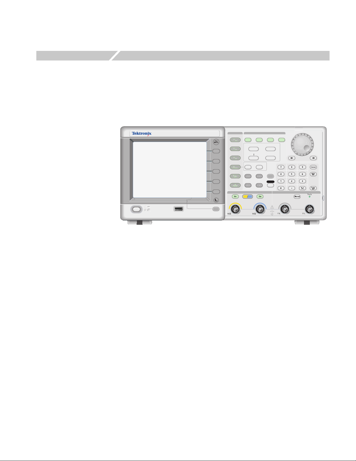
The AFG3000 Series Arbitrary/Function Generators front panel is divided into
easy to use functional areas. This section provides you with a quick overview of the
controls. Figure 1-1 shows the front panel of dual-channel model.
AFG
DUAL CHANNEL
3102
ARBITRARY/FUNCTION GENERATOR
USB
USB
Memory
Memory
Figure 1-1: Dual-channel model
1GS/s
100MHz
Sine
Square
Ramp
Pulse
Arb
Output
View
Run ModeFunction
Continuous Modulation
Frequency/Period Amplitude/High
Offset/Low
Leading/TrailingDuty/Width
Utility
Edit
Save RecallMore...
Channel
Ch1
Phase Delay
Ch2
Sweep Burst
Help
Default
TriggerTrigger
InputOutput Output
AFG3000 Series Arbitrary/Function Generators Reference Manual 1-1
Page 20
Operating Basics
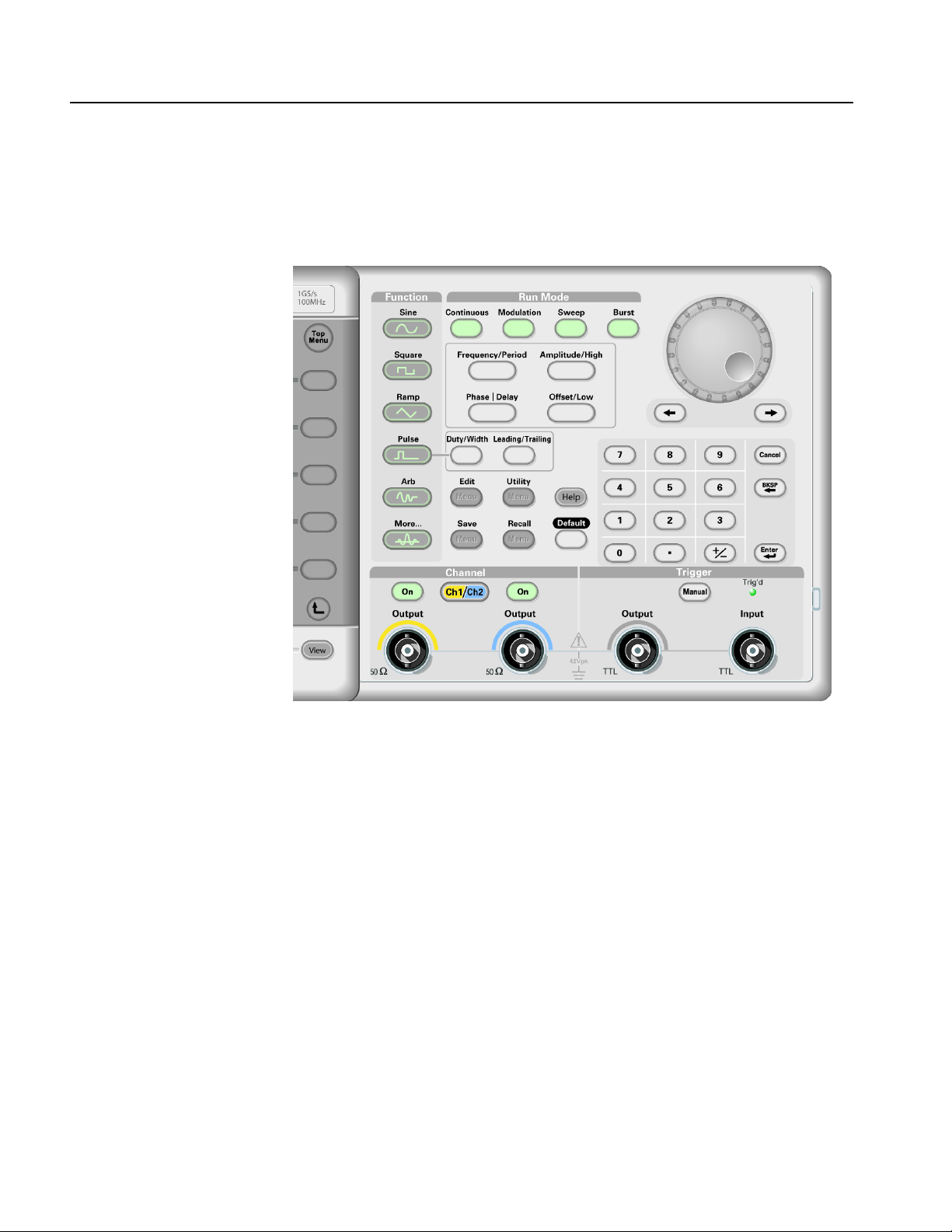
Front Panel Controls
This section introduces you to the front panel controls of the instrument and
provides a brief overview on how to use the front panel key controls.
Figure 1-2: Front panel controls
The AFG3000 Series Arbitrary/Function Generators front-panel key controls are
divided into the following categories:
Action buttons
Menu buttons
State buttons
Function buttons
Shortcut buttons
1-2 AFG3000 Series Arbitrary/Function Generators Reference Manual
Page 21

Operating Basics
Action Buttons
The Power (not shown in Figure 1-2), Upper Menu, Top Menu, View, and Manual
Trigger buttons are called action buttons. When you push these action buttons, it
will cause an action.
Power button. Pushing the power button once turns the instrument on. Pushing the
power button when the instrument is on will turn off the instrument.
Upper Menu button. Pushing the Upper Menu button returns the currently
displayed bezel menu to the upper level of the menu tree.
Top Menu button. The Top Menu button is used to return to the top level of the
menu tree from the current menu location.
View button. The View button is used to toggle the screen view format. The
arbitrary/function generator provides the following three screen view formats:
View format 1: Waveform parameter and graph display, see Figure 1-3
View format 2: Graph comparison, see Figure 1-4
View format 3: Waveform parameter comparison, see Figure 1-5 and
Figure 1-6
When the instrument is in one of the three display format, pushing the View button
will toggle through the three views in a repeating cycle in the order described
above.
When the instrument is in the Edit Menu, pushing the View button will toggle
between Edit text and graphical views. This is the only function of the
single-channel model view button.
When the instrument is in the Save/Recall, Utility, Output, or Help menu, pushing
the View button will have no effect.
AFG3000 Series Arbitrary/Function Generators Reference Manual 1-3
Page 22
Operating Basics
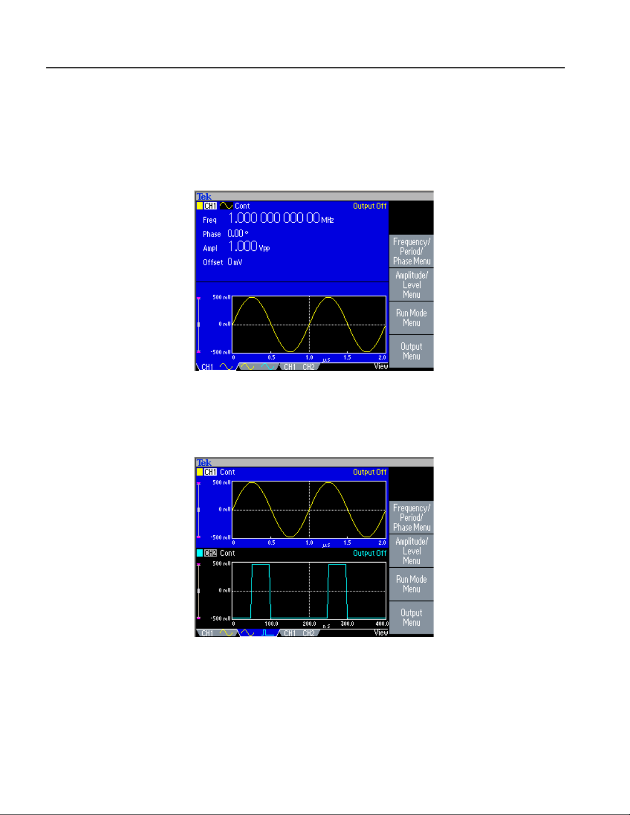
View Format 1. Figure 1-3 is a single channel parameter and graph setup display. In
this view, Channel 1 is selected with the Channel Select button. When Channel 2
is selected, the parameters and graph for Channel 2 will be displayed in this view.
You can easily toggle between the information for Channel 1 and Channel 2 with
this view.
Figure 1-3: Waveform parameter and graph display
View Format 2. Figure 1-4 is a graph compare view. In this view, the Channel Select
button selects the active graph. The selected channel is highlighted.
Figure 1-4: Graph comparison
1-4 AFG3000 Series Arbitrary/Function Generators Reference Manual
Page 23

Operating Basics
View Format 3. Figure 1-5 is a channel compare view. In this view, Channel 1 is
selected with the Channel Select button.
Figure 1-5: Waveform parameter comparison (CH1 selected)
In Figure 1-6, Channel 2 is selected with the Channel Select button.
Figure 1-6: Waveform parameter comparison (CH2 selected)
Manual Trigger button. Pushing the Manual Trigger button generates a trigger
event manually. The Manual Trigger is one of the trigger sources for sweep or burst
waveform. If you push the Manual Trigger button, the arbitrary/function generator
will initiate one sweep in the Trigger Sweep mode, or output a waveform that has
the specified number of cycles in the Burst mode. If the instrument is in Gated
mode, it outputs a waveform while the Manual Trigger button is depressed.
The Trig’d LED lights whenever the instrument responds to a trigger.
AFG3000 Series Arbitrary/Function Generators Reference Manual 1-5
Page 24

Operating Basics
Other Action buttons. The Enter button and the following related buttons are also
classified as Action buttons.
Enter button. The Enter button causes a numeric input to be updated.
+/– button. This button is only active when you are setting a value. The +/–
button changes the sign of the currently selected parameter from positive to
negative. If the value is already negative, this button makes it positive.
Cancel button. The Cancel button is active when you are setting a value.
Pushing the Cancel button closes the Units menu and restores the previous
value for the selected setting.
When the front-panel controls are locked, you can use the Cancel button to
unlock the front-panel controls. See page 1-10.
Backspace (BKSP) button. The BKSP button is only active when you are
setting a value in the Numeric Input Area. Pushing the BKSP button deletes
the currently selected digit.
Menu Buttons
The Edit, Utility, Save, Recall, Help, and Default buttons are called Menu buttons.
Edit button. The Edit button opens Edit menu. See Table 2-11 on page 2-14 for the
Edit menu map.
Utility button. The Utility button opens Utility menu. See Table 2-13 on page 2-23
for the Utility menu map.
Save button. The Save button opens the Save menu. See Table 2-10 on page 2-13
for the Save menu map.
Recall button. The Recall button opens the Recall menu. See Table 2-10 on
page 2-13 for the Recall menu map.
Help button. The Help button opens the built-in Help.
Default button. The Default button restores the instrument settings to the default
values. When you push this button, you will be prompted on the display with a
pop-up window message requesting you to confirm that you want to restore the
defaults. See Default Setup on page D-1 for the settings when you push the Default
button.
Run Mode buttons. When one of four Run Mode buttons is selected, the menu for
configuring the run mode is displayed on the screen. See State buttons on page 1-7.
1-6 AFG3000 Series Arbitrary/Function Generators Reference Manual
Page 25

Operating Basics
State Buttons
The Channel Select, CH1/CH2 Output and Run Mode buttons are called State
buttons.
Ch2
Channel Select button. The Channel Select button directly controls the
Ch1
display, toggling between the two channels. This button is used to select the
channel that you are currently interacting with. Only one channel can be selected
at a time.
When you push the Channel Select button on the Edit, Utility, Save, Recall, or Help
screen, the arbitrary/function generator returns to previous display. The displayed
channels do not toggle if you push the Channel Select button on those screen
menus. After restoring the main display area, pushing the Channel Select button
toggles between CH1 and CH2.
CH1/CH2 Output On button. The arbitrary/function generator allow you to turn on
and off the signal output for CH1 and CH2 independently. You can configure the
signal with the outputs off, to minimize the chance of sending a problematic signal
to your device. You can select either one or both of these buttons. Each button is lit
with an LED when in the On state.
Run Mode buttons. Only one Run Mode menu can be selected for each channel.
The Run Mode buttons are unique because they are both State and Menu buttons.
When one of four buttons is selected, that run mode is activated and the menu for
configuring that run mode is displayed on the screen. The selected button is lit with
an LED.
Continuous
Modulation
Sweep
Burst
If your instrument is a dual-channel model, Run Mode can be set independently for
each channel.
AFG3000 Series Arbitrary/Function Generators Reference Manual 1-7
Page 26
Operating Basics
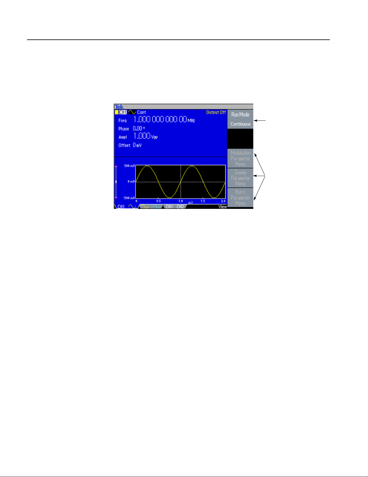
Select the Run Mode Menu bezel button from the default screen (see page 1-14)
to display the Run Mode menus. The Continuous mode is selected in Figure 1-7. If
you select Modulation, Sweep, or Burst as the Run Mode, the corresponding bezel
menu is highlighted.
Continuous Mode is
selected (active).
These are inactive bezel
menus.
Function Buttons
Figure 1-7: Run Mode menu (Continuous)
Only one of the Function buttons can be selected for each channel at a time. The
selected button will be lit with an LED.
Sine button. Pushing the Sine button selects the sine waveform, causing the Sine
button LED to turn on. See Table 2-1 on page 2-3 for the menu map.
Square button. Pushing the Square button selects the square waveform, causing the
Square button LED to turn on. See Table 2-1 on page 2-3 for the menu map.
Ramp button. Pushing the Ramp button selects the ramp waveform, causing the
Ramp button LED to turn on. See Table 2-2 on page 2-4 for the menu map.
Pulse button. Pushing the Pulse button selects the pulse waveform, causing the
Pulse button LED to turn on. See Table 2-3 on page 2-4 for the menu map.
Arb button. Pushing the Arb button causes the Arb waveform menu to be displayed
on the screen, and causes the Arb LED to turn on. See Table 2-4 on page 2-5 for
the menu map.
More... button. Pushing the More... button causes the More waveform menu to be
displayed on the screen, and causes the More... LED to turn on. See Table 2-5 on
page 2-6 for the menu map.
1-8 AFG3000 Series Arbitrary/Function Generators Reference Manual
Page 27

Operating Basics
Shortcut Buttons
The following six buttons are called Shortcut buttons and are provided as shortcuts
for experienced users. You can push this button while viewing any of the display
types. If you are not in view format 1, 2, or 3 (see page 1-3), pushing the shortcut
button will take you to the last view you used and highlight the selected setting.
Frequency/Period button. This button selects the setting that was last used
(Frequency or Period). If Frequency was selected, you can change the shortcut by
selecting Period with the bezel menu. The next time you push the
Frequency/Period button, Period will be selected. This shortcut button allows you
to select the setting and enter their numeric value using the front panel, without
requiring any bezel menu selection.
Amplitude/High button. This button selects the setting that was last used (Ampli-
tude or High Level).
Offset/Low button. This button selects the setting which was last used (Offset or
Low Level).
Duty/Width button. This button only operates when the Pulse function is selected
for the current channel. Otherwise, the button does nothing when pushed. The
instrument remembers which setting (Duty or Width) was last selected from the
bezel menu and highlights that setting when this shortcut button is pushed.
Knob and Arrow Keys
Leading/Trailing button. This button only operates when the Pulse function is
selected for the current channel, otherwise, the button does nothing when pushed.
The instrument remembers which setting (Leading Edge or Trailing Edge) was
last selected from the bezel menu and highlights that setting when this shortcut
button is pushed.
Phase | Delay button. This shortcut button is different from the other buttons. This
button does not toggle between two parameters. For example, if you push the
Phase | Delay shortcut button in the pulse parameter menu, Delay becomes active.
Pushing the Phase | Delay button again will have no effect, because there is no
Phase parameter in the pulse parameter menu. Similarly, when you push the Phase
| Delay button in the Sine, Square, or Ramp parameter menu, Phase becomes
active. Pushing the button again will have no effect, because there is no Delay
parameter in these menus.
The general purpose knob can be used to increase and decrease selected numeric
values. The arrow keys (digit select keys) are used to move the underbar to a field
that contains an editable number. This will allow you to change the digit with the
knob. Refer to page 1-15 for entering or changing numeric values using the knob
and the arrow keys.
AFG3000 Series Arbitrary/Function Generators Reference Manual 1-9
Page 28

Operating Basics
BNC Connectors
USB Memory
Refer to Figure 1-2 on page 1-2 for the locations of the front panel BNC connectors.
CH1 Output. This BNC connector will output the Channel 1 signal. This connector
will be deactivated when the Channel 1 output button is not selected. The load
impedance for this connection can be set in the Output Menu.
CH2 Output. Same functionality as Channel 1 Output. This output is not present in
the single channel instrument model.
Trigger Output. This connector provides a TTL level pulse synchronized with the
Channel 1 output. The connector provides a signal that will allow an oscilloscope
to synchronize with the arbitrary/function generator.
When you synchronize multiple arbitrary/function generators, the Trigger Output
on the master instrument is connected to the Trigger Input of the slave instrument.
Trigger Input. When the arbitrary/function generator is a slave to another device,
The Trigger Input connector will be used to synchronize the arbitrary/function
generator with the master device. Trigger signals from other devices can also be
input here.
The USB Memory connector is a host connector, which allows a USB client
memory device to be connected. You can perform the following tasks:
To Unlock Front Panel
Controls
Save or recall user-defined waveforms to/from a USB memory
Save or recall setups to/from files on a USB memory
Update your arbitrary/function generator firmware
CAUTION. Do not remove USB memory while writing or reading data. It may cause
data loss and the USB memory may be damaged.
When you attach a USB memory to the instrument, a caution message appears on
the screen. Do not remove the USB memory until the message disappears.
If you remove the USB memory while this caution message is displayed, it may
cause damage to the instrument.
The front panel may be locked by a remote user while the instrument is being
remotely controlled via GPIB, USB or Ethernet. When the front panel is locked, all
keys and buttons are disabled except the power switch. The “Lock” symbol at the
top right of the screen indicates that the instrument front-panel controls are locked.
To unlock the front-panel, use the remote command or push the front-panel Cancel
button twice in a row. This method is not applied if the arbitrary/function generator
is in the GPIB LLO (Local Lockout) state.
1-10 AFG3000 Series Arbitrary/Function Generators Reference Manual
Page 29
Display Area and Screen Interface
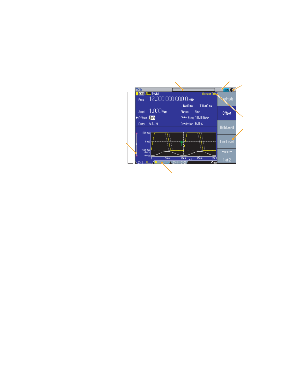
Figure 1-8 shows the main areas of the instrument display.
Operating Basics
Main Display Area
Message display area
Main display
area
Level meter
View tab
Numeric input is available
Knob is available
Output status
Bezel menu
Figure 1-8: Screen interface
Pushing the front-panel View button changes the view format of the main display
area. See page 1-3 for screen view formats.
View Tab. The view tabs correspond with the current view format.
Output Status. If the output is set to disable, the Output Off message is displayed
in this area. When you push the front-panel channel output button to enable the
output, the message will disappear.
From the Output menu, you can set the load impedance, invert a waveform, or add
an external signal to the CH1 output. The status will change based on the output
status.
AFG3000 Series Arbitrary/Function Generators Reference Manual 1-11
Page 30
Operating Basics
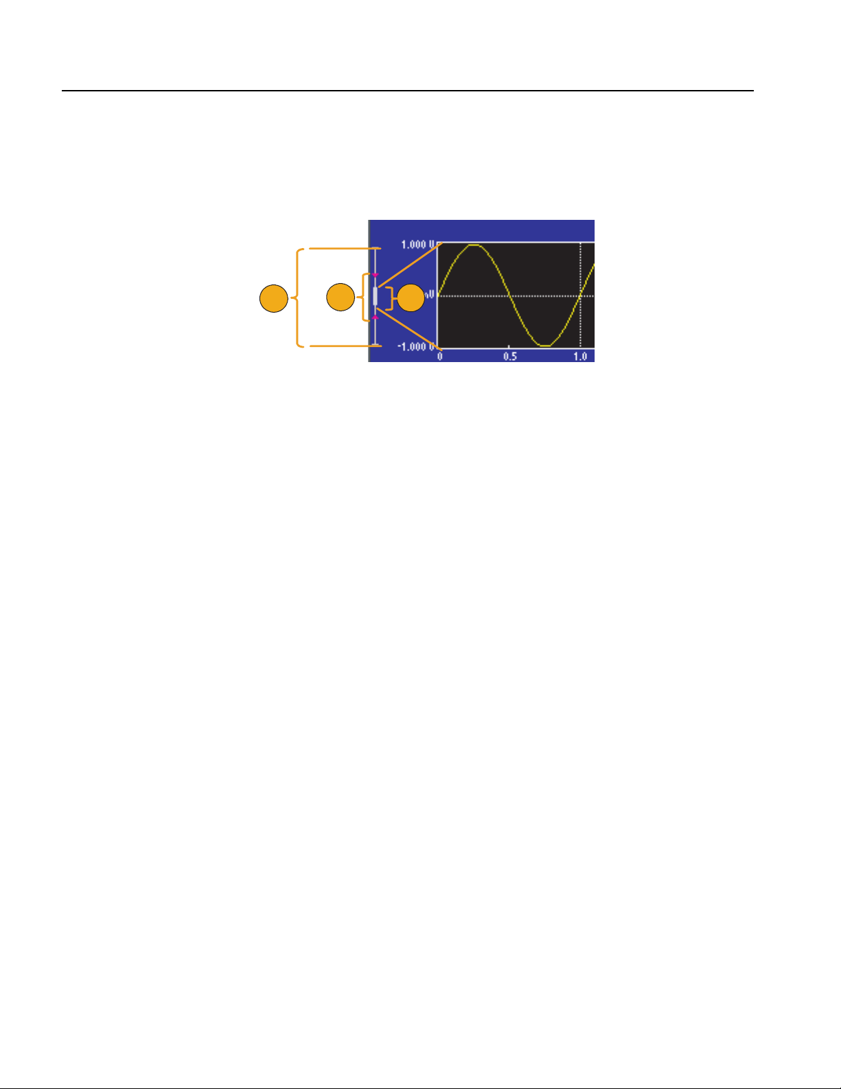
Level Meter. Amplitude level is displayed. To protect your DUT (device under test),
use the Output Menu to set the limit values for high level and low level. Figure 1-9
shows Level Meter.
Message Display Area
1
Figure 1-9: Level meter
1. Shows maximum amplitude level of your instrument.
2. Shows the range of high limit and low limit that you have set.
3. Shows the amplitude level that is currently selected.
A message that monitors hardware status such as clock or trigger is displayed in
this area.
The arbitrary/function generator displays a message at the top of the screen, which
conveys the following types of information about hardware status:
External Reference out of range
Waiting for Trigger
You can also display a text message in this area by using the following remote
command. See page 3-21.
2
3
DISPlay[:WINDow]:TEXT[:DATA]
1-12 AFG3000 Series Arbitrary/Function Generators Reference Manual
Page 31

Operating Basics
Bezel Menu Display Area
When you push a front panel button, the instrument displays the corresponding
menu on the right side of the screen. The menu shows the options that are available
when you push the unlabeled bezel buttons directly to the right of the screen. (Some
documentation may also refer to the bezel buttons as side-menu buttons or soft
keys.)
The AFG3000 Series Arbitrary/Function Generators use four types of menu button
status. See Figure 1-10.
Currently selected and active (focused)
Toggle button selection. This shows that
currently selected option (Internal) is
highlighted.
Inactive. This selection is currently not
available.
Normal (default) This shows unselected
state.
Figure 1-10: Graphical representation of button status
Focused (active) – Blue background and white type
The bezel menu item is currently selected.
Non-Focused – Medium gray background and white type, blue box around
type only
There are some toggle button selections within the bezel menus. For example,
Internal and External. You can specify either one but not both of these
parameters.
Inactive – Medium gray background and light gray type
This selection is currently not available because of the other instrument
settings.
Normal (default) – Medium gray background and white type
This is the currently unselected state.
AFG3000 Series Arbitrary/Function Generators Reference Manual 1-13
Page 32

Operating Basics
Waveform Parameters and Numeric Input
This section explains how to set or change the waveform parameters of the
arbitrary/function generator using the front-panel controls or bezel menu selection.
Changing Parameters
Using the Bezel Menu
The arbitrary/function generator outputs a sine waveform of 1 MHz frequency with
1V
by default. You can use the following two methods to set or change the
p-p
waveform parameters:
Using the bezel menu selection
Using the front-panel shortcut buttons (see page 1-17)
Figure 1-11 shows the default display of sine waveform.
Figure 1-11: Default display
Select the Frequency/Period/Phase Menu bezel button from the default display,
you can change the values of frequency, period, or phase.
Figure 1-12: Frequency/Period/Phase Menu
1-14 AFG3000 Series Arbitrary/Function Generators Reference Manual
Page 33

Operating Basics
Numeric Input
If you want to change the frequency value, push the Frequency bezel button. The
value of Freq in main display area changes to “selected status”. The Freq is
displayed in black type inside a white box. See Figure 1-13.
Frequency is selected
(active).
Freq is selected. The cursor is now under “1”.
Figure 1-13: Screen display with Frequency active (1)
To move the cursor, use the arrow keys.
Frequency is selected
(active).
The cursor is moved.
Figure 1-14: Screen display with Frequency active (2)
To change the value, use the general purpose knob. Turn the knob clockwise to
increase the value; turn the knob counterclockwise to decrease the value.
Frequency is selected
(active).
The value is changed to “5”.
Figure 1-15: Screen display with Frequency active (3)
AFG3000 Series Arbitrary/Function Generators Reference Manual 1-15
Page 34

Operating Basics
You can also change the value with the front-panel numeric key-pad. Entering any
value from the numeric key-pad will automatically change the bezel menu to Units.
See Figure 1-16.
The bezel menu is
changed to “Units”.
The value “2” is entered.
Figure 1-16: Screen display with Frequency active (4)
After entering the frequency value, push the Units bezel button or the front-panel
Enter button to complete the entry.
To change the amplitude value, push the Top Menu button, and then select the
Amplitude/Level Menu bezel button. You can change the values of amplitude,
offset, high level, or low level.
Figure 1-17: Amplitude/Level Menu
1-16 AFG3000 Series Arbitrary/Function Generators Reference Manual
Page 35

Operating Basics
Changing Parameters
Using the Shortcut
Buttons
The shortcut buttons are provided for experienced users. The buttons allow you to
select a setup parameter without using any bezel menu selection. The following
example shows how the Frequency/Period shortcut button works.
You can use the shortcut buttons while viewing any of the display formats. Push a
shortcut button to display the last view type and highlight the selected parameter
setting. Figure 1-18 is a sample screen of Pulse Width Modulation parameter menu
display.
Figure 1-18: PWM sample screen
From Figure 1-18, pushing the Frequency/Period shortcut button will change the
bezel menu to look like Figure 1-19.
Frequency is active.
Figure 1-19: PWM parameter menu (Freq is selected)
AFG3000 Series Arbitrary/Function Generators Reference Manual 1-17
Page 36

Operating Basics
You can now change the frequency value. If you push the Frequency/Period
shortcut button again, the active parameter will change to Period. See Figure 1-20.
Period is active.
Figure 1-20: PWM parameter menu (Period is selected)
The Frequency/Period shortcut button is used to select the setting that was last
used (Frequency or Period). If Frequency was selected, you can change the
shortcut by pushing the shortcut button again. The next time you push the
Frequency/Period button, Period will be selected.
NOTE. The Duty/Width and Leading/Trailing shortcut buttons are operational
only when Pulse is selected in the Functional button.
1-18 AFG3000 Series Arbitrary/Function Generators Reference Manual
Page 37

Rear Panel
120
VA
Operating Basics
Figure 1-21 shows the locations of the instrument rear panel connectors.
Security slot
ADD INPUT
LAN
USB
EXT REF OUT
EXT REF INPUT
EXT MODULATION CH2 INPUT
EXT MODULATION CH1 INPUT
Chassis ground screw
GPIB
Figure 1-21: Rear panel connectors
EXT REF INPUT. This input is used when synchronizing multiple arbitrary/function
generators or an arbitrary/function generator and another device.
EXT REF OUTPUT. This output is used when synchronizing multiple arbitrary/function generators or an arbitrary/function generator and another device.
ADD INPUT. (Dual-channel model only) Additional Input connector allows you to
input a signal from some other source and add that signal to CH 1 output.
EXT MODULATION CH 1 INPUT. A signal applied to the External Modulation CH 1
Input connector is used to modulate the CH 1 output signal. The signal input level
applied to this connector will control the modulation depth.
EXT MODULATION CH 2 INPUT. (Dual-channel model only) The External Modulation CH 2 Input connector is used to apply an external modulating signal to the CH
2 output signal. The signal input level applied to this connector will control the
modulation depth.
AFG3000 Series Arbitrary/Function Generators Reference Manual 1-19
Page 38

Operating Basics
USB. The USB connector is used to connect a USB controller.
LAN. This connector is used to connect the arbitrary/function generator to a
network. Connect a 10BASE-T or 100BASE-T cable here.
GPIB. The GPIB connector is used to control the arbitrary/function generator
through remote commands.
Security Slot. Use a standard laptop computer security cable to secure your arbitrary/function generator to your location.
Chassis Ground Screw. The chassis ground screw is used to ground the arbitrary/function generator. Use a unified coarse screw (#6-32, 6.35 mm length or
less).
1-20 AFG3000 Series Arbitrary/Function Generators Reference Manual
Page 39

Reference
Page 40

Page 41

Reference
Menu System
This section describes the menus associated with each front-panel menu button or
control.
The user interface of the AFG3000 Series Arbitrary/Function Generators was
designed for easy access to specialized functions through the menu structure.
When you push a front panel-button, the arbitrary/function generator displays the
corresponding menu on the right side of the screen. The menu shows the options
that are available when you push the unlabeled bezel buttons directly to the right of
the screen. (Some documentation may also refer to the bezel buttons as side-menu
buttons or soft keys.)
Using the Menu System
The arbitrary/function generator uses the following methods to display menu
options:
Submenu Selection. For some menus, you can use the bezel button to choose the
submenus. For example, when you push the I/O Interface bezel button in the Utility menu, the arbitrary/function generator displays the I/O Interface submenu
(GPIB or Ethernet).
Action. The arbitrary/function generator displays the type of action that will immediately occur when you push an action bezel button. For example, when you push
the front-panel Save button and then push the Save bezel button, the arbitrary/function generator saves the settings immediately.
Option Buttons. The arbitrary/function generator uses a different button for each
option. The currently selected option is highlighted. For example, the instrument
displays various language options when you push the Utility menu button and then
push the Language bezel button. To select the option, push the corresponding button. Option button is also called radio button.
Toggle. For some menus, pushing a bezel button will toggle the corresponding
menu options. For example, when you push the Power On bezel button in the Util-
ity menu, it will toggle between Default and Last. Pushing the Beeper bezel button will toggle between On and Off.
AFG3000 Series Arbitrary/Function Generators Reference Manual 2-1
Page 42

Reference
Menu Structure
This section describes the menus and operating details associated with each
front-panel menu button.
Sine/Square Menu, page 2-3
Ramp Menu, page 2-4
Pulse Menu, page 2-4
Arb Menu, page 2-5
More... Menu, page 2-6
Run Mode Menus
Continuous (No bezel menu for Continuous mode)
Modulation Parameter Menu, page 2-7
Sweep Parameter Menu, page 2-9
Burst Parameter Menu, page 2-11
Output Menu, page 2-12
NOTE. To access the Output menu, push the front-panel Top Menu button. The
arbitrary/function generator does not have the Output menu button on the front
panel. Refer to page 1-3 for the Top Menu button.
Save/Recall Menu, page 2-13
Edit Menu, page 2-14
Utility Menu, page 2-23
2-2 AFG3000 Series Arbitrary/Function Generators Reference Manual
Page 43

Reference
Sine/Square Menu
Table 2-1 shows the Sine and Square menu.
Table 2-1: Sine/Square menu
First level Second level Third level Description
Frequency/Period/
Phase Menu
Amplitude/Level Menu Amplitude Selects Amplitude as a
Run Mode Menu Continuous –––
Output Menu Refer to Table 2-9
1. Dual-channel model only.
2. dBm is used only for sine waveform.
Frequency Selects Frequency as a
parameter to be changed.
Per iod Se lects Period as a parameter
to be changed.
Frequency (Period)
CH1=CH2
Off On
1
Toggles between Off and On to
disable/enable the function that
sets the CH1 and CH2 to the
same value.
Phase Selects Phase as a parameter to
be changed.
Align Phase
1
Use to align the phase of two
channel signals.
parameter to be changed.
Offset Selects Offset as a parameter to
be changed.
High Level Selects High Level as a
parameter to be changed.
Low Level Selects Low Level as a
parameter to be changed.
-more- (1 of 2)
Units [Vpp] Vpp
Vrms
dBm
1
Level
CH1=CH2
Off On
2
Option buttons
Toggles between Off and On to
disable/enable the function that
sets the CH1 and CH2 to the
same value.
-more- (2 of 2)
Modulation Refer to Table 2-6
Sweep Refer to Table 2-7
Burst Refer to Table 2-8
AFG3000 Series Arbitrary/Function Generators Reference Manual 2-3
Page 44

Reference
Ramp Menu
Pulse Menu
Table 2-2 shows the Ramp menu.
Table 2-2: Ramp menu
First level Second level Description
Ramp Parameter
Menu
Frequency/Period/
Phase Menu
Amplitude/Level Menu Refer to Table 2-1
Run Mode Menu Continuous –––
Output Menu Refer to Table 2-9
Symmetry Sets the Ramp waveform symmetry to your
desired value.
Set to 0% Sets the Ramp waveform symmetry to 0%.
Set to 50% Sets the Ramp waveform symmetry to 50%.
Set to 100% Sets the Ramp waveform symmetry to 100%.
Refer to Table 2-1
Modulation Refer to Table 2-6
Sweep Refer to Table 2-7
Burst Refer to Table 2-8
Table 2-3 shows the Pulse menu.
Table 2-3: Pulse menu
First level Second level Description
Pulse Parameter
Menu
Frequency/Period/
Delay Menu
Amplitude/Level Menu Refer to Table 2-1
Run Mode Menu Continuous –––
Output Menu Refer to Table 2-9
1. Dual-channel model only.
Duty Selects Duty as a parameter to be changed.
Width Selects Width as a parameter to be changed.
Leading Edge Selects Leading Edge as a parameter to be
changed.
Trailing Edge Selects Trailing Edge as a parameter to be
changed.
Frequency Selects Frequency as a parameter to be
changed.
Per iod Se lects Period as a parameter to be changed.
Frequency (Period)
CH1=CH2
Off On
Lead Delay Selects Lead Delay as a parameter to be
Recover
Lead Delay
Modulation Refer to Table 2-6
Burst Refer to Table 2-8
1
Toggles between Off and On to disable/enable
the function to set the CH1 and CH2 to the same
value.
changed.
1
Use to align the lead delay of two channel
signals.
2-4 AFG3000 Series Arbitrary/Function Generators Reference Manual
Page 45

Reference
Arb Menu
The arbitrary/function generator can output a user-defined waveform that is stored
in the internal memory, Edit Memory, or a USB memory. Table 2-4 shows the Arb
menu.
Table 2-4: Arb menu
First level Second level Description
Arb Waveform Menu Memory
Internal
USB
(blank)
Change Directory Opens a directory in a USB memory.
OK
Cancel
Frequency/Period/
Phase Menu
Amplitude/Level Menu Refer to Table 2-1
Run Mode Menu Continuous –––
Modulation Refer to Table 2-6
Sweep Refer to Table 2-7
Burst Refer to Table 2-8
Output Menu Refer to Table 2-9
Selects a memory type. (Internal or USB)
Refer to page 2-30 for file operations.
Refer to Table 2-1
To output a user-defined waveform, you have two options:
Output the contents of Edit Memory
Output one of user-defined waveforms stored in the internal or in a USB
memory
To output a user-defined waveform, you must first save the file in the internal or
USB memory. You can save up to four user-defined waveforms in the internal
waveform memory. Waveform data in the Edit Memory can also be output, but the
contents of Edit Memory is deleted when the instrument power is turned off.
NOTE. When the arbitrary/function generator outputs an Arb waveform, the
peak-to-peak voltage of the measurement result is the same as the setup value if the
waveform data is normalized.
AFG3000 Series Arbitrary/Function Generators Reference Manual 2-5
Page 46

Reference
More... Menu
Table 2-5 shows the More... menu.
Table 2-5: More menu
First level Second level Description
More Waveform Menu Sin(x)/x Option buttons
Noise
DC
Gaussian
-more- (1 of 2)
Lorentz Option buttons
Exponential Rise
Exponential Decay
Haversine
-more- (2 of 2)
Frequency/Period/
Phase Menu
Amplitude/Level Menu Refer to Table 2-1
Run Mode Menu Continuous –––
Modulation Refer to Table 2-6
Sweep Refer to Table 2-7
Burst Refer to Table 2-8
Output Menu Refer to Table 2-9
Refer to Table 2-1
NOTE. When the arbitrary/function generator outputs Sin(x)/x, Gaussian, Lorentz,
Exponential Rise, Exponential Decay, or Haversine waveforms, the peak-to-peak
voltage is defined as twice the 0 to peak value.
2-6 AFG3000 Series Arbitrary/Function Generators Reference Manual
Page 47

Reference
Modulation Parameter
Menu
Table 2-6 shows the Modulation Parameter Menu.
Table 2-6: Modulation parameter menu
First level Second level Description
Modulation
Type
[AM]
[AM] Source
Internal
External
AM, FM, PM, PWM
Frequency,
or FSK Rate
Modulation Shape
Depth/Deviation/
Hop Frequency
1. If you specify Internal as the memory type, you can select the modulation shape from the following:
Sine
Square
Triangle
Up Ramp
Down Ramp
Noise
Arb (User1 to User4)
Edit Memory
AM
FM
PM
FSK
PWM
1
Memory
Internal
USB
(blank)
Change Directory Opens a directory in a USB memory.
OK
Cancel
Selects modulation type.
Selects modulation source (internal or external)
for AM, FM, PM, FSK, or PWM.
Sets modulation frequency or FSK rate.
Selects a memory type (internal or USB).
Sets modulation depth for AM, deviation for FM
and PM, or Hop Frequency for FSK.
Amplitude Modulation. Amplitude modulation is a modulation technique in which
the amplitude of the carrier frequency is modified by the amplitude of the modulating waveform (internal or external modulation source).
The modulation depth is expressed as a percentage and represents the extent of the
amplitude variation.
Frequency Modulation. Frequency modulation is a modulation technique in which
the carrier frequency is modified by the amplitude of the modulating waveform.
The carrier frequency must always be greater than or equal to the deviation. Also
the sum of the carrier frequency and deviation must be less than or equal to the
maximum frequency for the selected waveform.
AFG3000 Series Arbitrary/Function Generators Reference Manual 2-7
Page 48

Reference
Phase Modulation. Phase modulation is similar to FM (Frequency modulation), but
in PM, the phase of the carrier waveform is varied by the amplitude of the modulating waveform.
Frequency Shift Keying. Frequency shift keying modulation is a modulation technique that shifts the output signal frequency between two frequencies: the carrier
frequency and the FSK Hop frequency.
Pulse Width Modulation. Pulse width modulation is a modulation technique in
which the width of a pulse waveform is varied by the voltage of the modulating
waveform.
2-8 AFG3000 Series Arbitrary/Function Generators Reference Manual
Page 49

Reference
Sweep Parameter Menu
Table 2-7 shows the Sweep Parameter Menu.
Table 2-7: Sweep parameter menu
First level Description
Start Frequency Numeric input. Sets start frequency.
Stop Frequency Numeric input. Sets stop frequency.
Sweep Time Numeric input. Sets sweep time.
Return Time Numeric input. Sets return time.
-more- (1 of 3)
Center Frequency Numeric input. Sets center frequency.
Span Numeric input. Sets frequency span.
Hold Time Numeric input. Sets hold time.
Ty p e
Linear
Logarithm
-more- (2 of 3)
Mode
Repeat
Trigger
Source
Internal
External
Slope
Pos itive
Negative
Trigger Interval Numeric input. Sets trigger interval.
-more- (3 of 3)
Selects sweep type (Linear or Logarithm). See Figure 2-1.
Selects sweep mode (Repeat or Trigger).
Selects trigger source (Internal or External).
Selects trigger slope (Positive or Negative). Available only when you
select External as a trigger source.
Available only when you select Internal as a trigger source.
The sweep function outputs a waveform with the output signal frequency varying
linearly or logarithmically.
Stop frequency
Start frequency
Linear sweep
Sweep time
Logarithmical sweep
Sweep time
Figure 2-1: Sweep type
AFG3000 Series Arbitrary/Function Generators Reference Manual 2-9
Page 50

Reference
When sweep is taking place, the frequency sweeps from start frequency to stop frequency. Refer to Figure 2-2.
Frequency
Stop freq.
Frequency
span
Center
frequency
Start freq.
Hold timeSweep time Return time
Time
Figure 2-2: Frequency sweep
The instrument sweeps from a low frequency to a high frequency when start frequency is set to be lower than stop frequency (start frequency < stop frequency).
The instrument sweeps from a high frequency to a low frequency when start frequency is set to be higher than stop frequency.
The frequency range differs based on the selected waveform types. For frequency
sweep, you can select a sine, square, ramp, or arbitrary waveform. Pulse, DC, and
Noise waveforms cannot be selected.
You can select one of the following two operation modes:
Repeat. A continuous sweep is output at a rate specified by the sweep time, hold
time, and return time.
Tri gg er. One sweep waveform is output when a trigger input is received.
You can select a trigger source from an external signal applied to the front-panel
Trigger Input connector, the trigger signal generated internally, the manual trigger,
or the remote interface.
2-10 AFG3000 Series Arbitrary/Function Generators Reference Manual
Page 51

Reference
Burst Parameter Menu
Table 2-8 shows the Burst Parameter Menu.
Table 2-8: Burst parameter menu
First level Description
1-Cycle Sets burst count to 1.
N-Cycle Sets burst count to N. (N=1 to 1,000,000)
Inf-Cycle Sets burst count to Infinite.
Gate Selects gated burst mode.
-more- (1/2)
Delay Sets trigger delay between the receipt of the trigger and the start of the
burst waveform. The range is 0 to 500 s.
Source
Internal
External
Slope
Pos itive
Negative
Trigger Interval Sets trigger interval. Available only when you select Internal as a trigger
-more- (2/2)
Select trigger source (Internal or External).
Selects trigger slope (Positive or Negative). Available only when you
select External as a trigger source.
source.
Triggered Burst Mode. When a trigger event occurs in the burst mode, the waveform is output for the number of cycles specified by the Burst Parameter Menu.
Once the triggered burst mode is selected, the arbitrary/function generator will wait
for a trigger event to occur.
A specified number (burst count) of waveform cycles are output when the instrument receives a trigger input from the internal trigger source, an external trigger
source, a remote command, or the Manual Trigger button.
Gated Burst Mode. In the gated burst mode, the output is enabled or disabled based
on the internal gate signal, an external signal applied to the front panel Trigger
Input connector, or a remote command. While the gate signal is true or the front
panel Manual Trigger button is depressed, the instrument outputs a continuous
waveform.
When the trigger source is set to Internal, the trigger interval can be set. The setting range of trigger interval is 1 ms to 500 s. The default is 1 ms.
When the trigger source is set to External, you can select Positive or Negative as
the trigger slope. The instrument will trigger on the rising edge (Positive) or falling
edge (Negative) of the signal applied to the front-panel Trigger Input connector.
AFG3000 Series Arbitrary/Function Generators Reference Manual 2-11
Page 52

Reference
Output Menu
Table 2-9 shows the Output Menu. To access the Output menu, push the front-panel
Top Menu button, and then push the bottom bezel button.
Table 2-9: Output menu
First level Second level Description
Load Impedance 50 Ω Option buttons. Set the load impedance to 50 Ω.
Invert
Off On
Limit High Limit Numeric input.
Noise Noise Add
External Add
3
Off On
1. Range: 1 Ω to 10 kΩ.
When dBm is currently selected for output amplitude units, the amplitude units setting
is automatically changed to V
2. Range: 0% to 50% of amplitude setting (V
The maximum value of noise range is limited by waveform and amplitude range.
3. AFG3100 and AFG3200 series only.
1
Load
Option buttons & Numeric input.
You can set the load impedance to any value
from 1 Ω to 10 kΩ.
High Z Option buttons. Select high impedance.
Selects Invert On to invert a waveform polarity.
Low Limit
Specifies the higher and lower amplitude limit.
See Level Meter on page 1-12.
Selects Noise Add On to add the internal noise
Off On
Noise Level
2
to a waveform.
Sets the noise level.
Selects External Add On to add an external
signal to the CH 1 output signal.
if you select high impedance.
p-p
) of signal waveform, resolution 1%
p-p
Load Impedance. The output impedance of the AFG3000 series is 50
nect a load other than 50
Ω, the displayed Amplitude, Offset, and High/Low values
Ω. If you con-
are different from the output voltage. To make the displayed values same as output
voltage, you need to set load impedance.
Noise Add. When you set Noise Add to On, the amplitude of output signal is
reduced to 50%.
2-12 AFG3000 Series Arbitrary/Function Generators Reference Manual
Page 53

Reference
Save/Recall Menu
The Save and Recall menus store or recall arbitrary/function generator setups. The
setups are stored in either internal setup memory or USB memory.
Table 2-10: Save/Recall menu
Save or Recall First level Second level Description
Save Memory
Internal
USB
Save Saves the instrument
Save As Enter Character Refer to page 2-34 for
OK
Cancel
Change Directory Opens a directory.
-more- (1/2)
Lock/Unlock Locks or unlocks a file.
Erase Erases a file.
(blank)
Make Directory Enter Character Refer to page 2-30 for
OK
Cancel
-more- (2/2)
Recall Memory
Internal
USB
Recall Recalls the instrument
(blank)
Change Directory Opens a directory.
(blank)
Selects a memory type
(Internal or USB).
settings to the
specified setup
memory location.
entering a file name.
file operations.
Selects a memory type
(Internal or USB).
settings from the
specified file.
The arbitrary/function generator has four storage locations in non-volatile memory
to store the instrument setups. The locations are numbered 1 through 4. The instrument uses location 0, which is called “last setup memory”, to overwrite the instrument setups at power off.
You can select the instrument settings that are restored when you power on the
instrument. If you select Power On Last in the Utility menu, the instrument will
restore the last powered-off settings the next time you power on the instrument.
(See the Utility Menu on page 2-23.)
The Lock/Unlock menu allows you to lock the file against accidental overwrite.
When a memory location is locked, a lock icon appears on the screen.
AFG3000 Series Arbitrary/Function Generators Reference Manual 2-13
Page 54

Reference
Edit Menu
The Edit menu is used to create or edit user-defined waveforms and to import or
export waveforms. To output a user-defined waveform, waveform data must be
created in the Edit Memory and then stored in the internal or a USB memory.
Although you can output the content of Edit Memory, the content of Edit Memory
will be deleted when the instrument is powered off.
There are three ways to create a waveform in the Edit Memory:
Create a waveform file using the Edit Menu
Copy a waveform file using remote commands
Import a waveform file using the ArbExpress software
Table 2-11: Edit menu
First level Second level Description
Number of Points Sets the number of points of waveform to be
created or the length of edit memory.
The default is 1000.
New Sine Writes a standard waveform to Edit Memory.
Square
Pulse
Ramp
Noise
Operation Line Opens Line submenu. See Table 2-12.
Data Opens Data submenu. See Table 2-12.
Cut Opens Cut submenu. See Table 2-12.
(blank)
(blank)
Read from... Memory
Internal
USB
Read Load one of the user-defined waveforms, which
(blank)
Change Directory Opens a directory. This menu item is available
Cancel
-more- (1/3)
(The contents of Edit Memory will be
overwritten.) You can select a waveform from
five standard waveforms. The written waveform
has the number of points specified by the
Number of Points bezel menu.
Selects a memory type (Internal or USB).
is stored in the internal or USB memory, to Edit
Memory. Once Read is executed, the edit
waveform is overwritten.
when USB is selected.
2-14 AFG3000 Series Arbitrary/Function Generators Reference Manual
Page 55

Table 2-11: Edit menu (cont.)
First level Second level Description
Paste at Beginning Memory
Internal
USB
Paste Pastes a waveform at the beginning of the
(blank)
Change Directory Opens a directory. This menu item is available
Cancel
Paste at End Memory
Internal
USB
Paste Pastes a waveform at the end of the current
(blank)
Change Directory Opens a directory. This menu item is available
Cancel
(blank)
Write to... Memory
Internal
USB
Write Saves the current waveform to the internal or
Write As Opens the submenu to enter a file name.
Change Directory Opens a directory. This menu item is available
-more- (1/2)
Lock/Unlock Locks or unlocks a file.
Erase Erase a file.
(blank)
Make Directory Creates a new directory. This menu item is
-more- (2/2)
-more- (2/3)
Zoom Fit Adjusts the graph scale and display the
(blank)
(blank)
(blank)
-more- (3/3)
Selects a memory type (Internal or USB).
current waveform.
when USB is selected.
Selects a memory type (Internal or USB).
waveform.
when USB is selected.
Selects a memory type (Internal or USB).
USB memory.
See page 2-32.
when USB is selected.
available when USB is selected.
complete waveform cycle.
Reference
AFG3000 Series Arbitrary/Function Generators Reference Manual 2-15
Page 56

Reference
Number of Points. This bezel menu sets the number of points of the waveform to be
created or the length of Edit Memory. The point can be set to a value in the following range:
Waveform Length: 2 to 131,072
If a waveform is already written to Edit Memory and Number of Points is set to a
value smaller than the number of points in that waveform, then the data for the
points starting at that value plus one will be lost. For example, if Number of Points
is set to 500 in the state where a waveform with 1000 points has been written to
Edit Memory, the waveform data for points 1 to 500 will remain without change
but the data from point 501 will be lost.
If a waveform is already written to Edit Memory and Number of Points is set to a
value greater than the number of points in that waveform, then the data for the
points starting at that value plus one to the point identified by the Number of
Points will be set to the zero level. For example, if Number of Points is set to 1500
in the state where a waveform with 1000 points has been written to Edit Memory,
the waveform data for points 1 to 1000 will remain without change and the data
from point 1001 to point 1500 will be set to zero level. See Figure 2-3 for an example using the Number of Points parameter.
Sine waveform with 1000 points
1000
Sine waveform with 1000 points
1000
Set to 500
Lost data
500
Set to 1500
Added data
1000 1500
Figure 2-3: Number of Points
New. Pushing the New bezel button will display a standard waveform selection
submenu. You can select a standard waveform from five waveform types (Sine,
Square, Pulse, Ramp, and Noise). For example, selecting Sine will write a sine
2-16 AFG3000 Series Arbitrary/Function Generators Reference Manual
Page 57

Reference
waveform into Edit Memory. The waveform has the number of points specified by
the Number of Points bezel menu. If waveform data is already stored in the Edit
Memory, the existing waveform data will be lost, and the new waveform will overwrite the old data.
Operations Submenu (Line, Data, and Cut). For each of the Operations submenus,
you must push the Execute bezel button to implement the edit operation.
Table 2-12: Operations submenu
First level Second level Description
Line From X1 Use to edit a line linearly by interpolating from a
Y1
To X 2
Y2
Execute
Data X Use to change the specified data point in the
Y
(blank)
(blank)
Execute
Cut From X1 Use to delete an area between specified points in
(blank)
To X 2
(blank)
Execute
(blank)
(blank)
specified point in the waveform currently being
edited to another specified point.
waveform currently being edited.
the waveform currently being edited.
AFG3000 Series Arbitrary/Function Generators Reference Manual 2-17
Page 58

Reference
Using the Cursors. You can use cursors to edit a waveform. To use cursors, select
the Operations submenu in the Edit menu. Figure 2-4 is a sample of Line edit
screen.
Figure 2-4: Using the Cursor (Line edit)
In the Line edit screen, there are two cursor types: X1 cursor and X2 cursor. Use
the From X1 or To X2 bezel button to select which cursor to move. To move the
X1 cursor, push the From X1 bezel button and then turn the general purpose knob.
Or, you can enter a value for the point X1 using the numeric keypad. Entering a
value and then pushing the front-panel Enter button will move the cursor to the
specified point. To move the X2 cursor, push the To X2 bezel button and then turn
the knob or enter a value.
After specified two points, push the Execute bezel button to implement the edit
operation. The Line edit is applied to the portion between the two cursors (X1 and
X2).
When you select Operations > Data, only one cursor is displayed. The edit operation is applied to the specified point.
When you select Operations > Cut, two cursors are displayed like Line edit. The
edit operation is applied to the portion between the two cursors.
2-18 AFG3000 Series Arbitrary/Function Generators Reference Manual
Page 59

Reference
Line (Line Edit). The Line edits by linearly interpolating from a specified point in
the waveform currently edited to another specified point as shown in Figure 2-5.
Before executing Line edit
After executing Line edit
Figure 2-5: Line Edit example
Data (Edit by Data Point). The Data edits a specified point in the waveform cur-
rently being edited.
Data – Graph display
Data – Table display
Figure 2-6: Operation – Edit by Data Point
If you enter a number that exceeds the number of points in the current waveform,
the entered value will be automatically changed to the number of points in the current waveform.
If you push the Execute bezel button in the Data operation, the instrument will
auto-increment to the next point. For example, you specify a data point X and then
push Execute, the instrument will automatically move from point X to X + 1 in
anticipation of your next input.
AFG3000 Series Arbitrary/Function Generators Reference Manual 2-19
Page 60

Reference
Cut (Cut by Data Points). The Cut deletes an area between specified points in the
waveform. When Cut is selected, two values can be input (From X1 and To X2).
See Figure 2-7.
Before executing Cut
After executing Cut
Figure 2-7: Cut example
NOTE. Data that has been deleted cannot be recovered.
Read from... Push the front-panel Edit button and then push the Read from... >
Memory bezel menu to load a waveform file from the internal memory or a USB
memory into Edit Memory.
2-20 AFG3000 Series Arbitrary/Function Generators Reference Manual
Page 61

Reference
Paste at Beginning. The Paste at Beginning inserts the contents of the user wave-
form memory (User1, User2, User3, or User4), USB memory, or the current
contents of Edit Memory at the beginning of the waveform that is currently being
edited. When this operation is executed, the Number of Points setting is automatically modified. If this operation would cause the waveform to exceed 131,072
points, the waveform insertion will not be executed.
Waveform in Edit Memory
1000
Stored waveform is pasted at the front of the
waveform being edited.
Figure 2-8: Paste at Beginning
Waveform stored in internal or USB memory
Waveform after executing Paste at Beginning
1000
2000
1000
AFG3000 Series Arbitrary/Function Generators Reference Manual 2-21
Page 62

Reference
Paste at End. The Paste at End appends the contents of the user waveform
memory (User1, User2, User3, or User4), USB memory, or the current contents of
edit memory at the end of the waveform currently being edited. When this operation is executed, the Number of Points setting is automatically modified. If this
operation would cause the waveform to exceed 131,072 points, the waveform
append will not be executed.
Waveform in Edit Memory
1000
Waveform after executing Paste at Beginning
Figure 2-9: Paste at End
1000
Waveform stored in internal or USB memory
1000
Stored waveform is pasted at the end of the
waveform being edited.
2000
Write to... The currently edited waveform is in Edit Memory. If the instrument
power is turned off, the contents of Edit Memory will be lost. To allow this waveform to be used the next time the power is turned on, the contents of Edit Memory
must be saved into the user waveform memory or a USB memory.
For more information on saving a user-defined waveform file, refer to Saving a
Waveform File on page 2-31.
2-22 AFG3000 Series Arbitrary/Function Generators Reference Manual
Page 63

Reference
Utility Menu
The Utility menu provides access to utilities used by the arbitrary/function generator such as language selection, instrument diagnostics, and user preferences.
Table 2-13: Utility menu
First level Second level Third level Description
I/O Interface GPIB Address Sets the instrument
GPIB address.
Ethernet
Configuration
Talk/Listen
Off Bus
1
IP Address Sets an IP address
Subnet Mask Sets a subnet mask
Default Gateway Sets a default gateway
2
DHCP
Off On
Select Talk/Listen to
enable the GPIB bus
communication.
Select Off Bus to
isolate the instrument
from the GPIB bus
communication.
manually.
manually.
manually.
Select DHCP On to
assign an IP Address
automatically.
Select DHCP Off to
assign an IP Address
manually.
Language English Selects a language to display on the instrument
French
German
Japanese
-more- (1 of 2)
Korean
Simplified Chinese
Traditional Chinese
Russian
-more- (2 of 2)
screen.
After selecting a desired language, the bezel
menu, pop-up message, and built-in help are
displayed in the selected language. The main
display area (see page 1-11) is not translated.
AFG3000 Series Arbitrary/Function Generators Reference Manual 2-23
Page 64

Reference
Table 2-13: Utility menu (cont.)
First level Second level Third level Description
System Trigger Out
Trigger
Sync
Clock Ref
Internal
External
Power O n
Default
Last
Secure Select Secure to erase all data except Mac
-more- (1 of 2)
Contrast Select Contrast to change the instrument
Screen Saver
Off On
Select Tri gg er to generate the trigger signal for
the oscilloscope.
Select Sync to synchronize multiple AFG3000
series instruments.
Select Internal to accept the internal reference
clock.
Select External to accept an external reference
clock.
Select Default to set the instrument power-on
status to the default settings.
Select Last to set the instrument power-on
status to the last powered-off settings.
Address, calibration data, and the instrument
serial number.
display contrast.
Select Screen Saver Off to deactivate the
screen saver.
Select Screen Saver On to activate the screen
saver.
Click Tone
Off On
Beeper
Off On
-more- (2 of 2)
Status Setup Select Setup to list the CH1 and CH2 waveform
Misc.
(blank)
Page Up Returns to previous page.
Page Down Moves to next page.
-more- (1 of 3)
Select Click Tone Off to deactivate the click
sound.
Select Click Tone On to activate the click
sound.
Select Beeper Off to deactivate the beeper
sound.
Select Beeper On to activate the beeper sound.
parameter configuration.
Select Misc. to list the instrument network
configuration and user preferences.
2-24 AFG3000 Series Arbitrary/Function Generators Reference Manual
Page 65

Reference
Table 2-13: Utility menu (cont.)
First level Second level Third level Description
Diagnostics/
Calibration
Backup/
3
Restore
Channel Copy CH1 -> CH2 Copies the CH1 waveform parameter settings to
(blank)
-more- (2 of 3)
Firmware Update
(blank)
Security Menu Access Protection Enter Character Use Security Menu to
-more- (3 of 3)
1. To connect your instrument to a network, you must first obtain information from your network
administrator. The procedure for entering the Ethernet network parameters depends on your
network configuration.
2. If your network supports DHCP (Dynamic Host Configuration Protocol), select the DHCP On so that
the instrument can automatically set its network address through DHCP.
3. These menus are available only when a USB memory is inserted correctly to the instrument.
Execute Diagnostics Performs the instrument diagnostics.
Execute Calibration Performs the instrument self calibration.
Ty p e
Selects file type (Setup or Arb).
Setup
Arb
Backup
Internal ->
Copies the contents of internal memory to a
USB memory.
USB Memory
Restore
Internal <-
Copies the files in the USB memory to the
internal memory.
USB Memory
Change Directory Opens a directory in a USB memory.
Make Directory Creates a new directory in a USB memory.
CH2.
CH2 -> CH1 Copies the CH2 waveform parameter settings to
CH1.
3
Execute Performs the instrument firmware update.
(blank)
(blank)
Change Directory Opens a directory in a USB memory.
Cancel
OK
Cancel
limit access to
Firmware update.
Change Password Enter Character Opens Change
OK
Password page.
Cancel
AFG3000 Series Arbitrary/Function Generators Reference Manual 2-25
Page 66

Reference
Connecting to a GPIB Network. The GPIB Interface can be used for remotely controlling the arbitrary/function generator from an external device (such as a PC).
Refer to Syntax and Commands on page 3-1 for information about remote control
commands.
Connecting to a Ethernet Network. To connect the arbitrary/function generator to a
LAN, use a 10 Base-T or 100 Base-T cable. Connect a LAN cable to the LAN port
on the rear panel. See page 1-19 for the location of the LAN port.
Synchronous Operation. By synchronizing multiple arbitrary/function generators,
you can configure the multichannel arbitrary/function generator. To synchronize
multiple arbitrary/function generators, connect the instruments as follows:
Use a BNC cable to connect the front-panel Trigger Output connector of the
master unit and the Trigger Input connector of the slave unit.
Use another BNC cable to connect the EXT REF OUTPUT connector on the
rear panel of the master unit and the EXT REF INPUT connector of the slave
unit.
NOTE. The EXT REF OUTPUT connector is not present on the AFG3021B and
AFG3022B rear panel.
1. Push the front-panel Utility button, and then push the System bezel button to
display the System menu.
2. Set the master unit as follows:
Trigger Out – Sync
Clock Ref – Internal
3. Set the slave unit as follows:
Clock Ref – External
4. Select Burst as the Run Mode for both the master and slave units.
5. Push the -more- bezel button of the slave unit, and select External as (trigger)
Source.
To synchronize multiple instruments, you must stop running output signals
once before triggering using the Burst mode.
2-26 AFG3000 Series Arbitrary/Function Generators Reference Manual
Page 67

Reference
Power-on Setting. You can select the arbitrary/function generator settings that are
restored when the instrument is powered on. By default, the arbitrary/function generator is set to restore the default settings at power-on. To change the power-on settings, use the Utility > System > Power On bezel menu. To restore the last
powered-off settings next time you power on the instrument, select Last.
Secure. The Secure function erases all the waveform/setup data in the internal
memory. This is sometimes useful when you are storing data that is confidential
and you must transport the instrument for servicing or demonstrations.
CAUTION. Executing Secure will erase all setups and waveform data files in the
internal memory. Make sure you want to remove all data before execution. You
cannot recover the deleted files.
Diagnostics and Calibration. From the Utility menu, you can perform the self test
and self calibration routine.
The self test can be performed by selecting the Utility > -more- > Diagnos-
tics/Calibration > Execute Diagnostics bezel menu. The test checks whether the
instrument is operating correctly. These diagnostics can be helpful when repairing
the instrument.
The self calibration allows the instrument to operate with correct precision.
NOTE. The self calibration must be executed at an ambient temperature of between
+20 °C and +30 °C (+68 °F to +86 °F), when a warm-up period of approximately
20 minutes has passed.
CAUTION. Do not power off the instrument during self calibration.
Backup/Restore. The Backup function is provided for copying the current arbi-
trary/function generator information (instrument setups or user-defined waveforms) to a USB memory with a single button push. Pushing the Backup Internal
-> USB Memory button will copy the internal memory contents to a USB memory.
The Restore function is provided for copying the contents of USB memory to the
internal memory.
AFG3000 Series Arbitrary/Function Generators Reference Manual 2-27
Page 68

Reference
Firmware Update. You can use the Utility menu to update your arbitrary/function
generator instrument firmware. If Tektronix offers a newer version of firmware,
download the firmware file to your USB memory from the Tektronix Web site.
1. Go to www.tektronix.com.
2. Download a newer version of firmware to your PC.
3. Unzip the downloaded file, and copy the file to your USB memory.
4. Connect the USB memory to your arbitrary/function generator.
5. Push the front-panel Utility button.
6. Push the -more- bezel button twice, and then select Firmware Update.
7. Select the downloaded firmware file and then push the Execute bezel button.
8. After the update, power the instrument off and then back on to activate the new
firmware.
NOTE. To check your instrument firmware version, push the front-panel Utility
button. The version information is displayed on the screen.
CAUTION. Updating your instrument firmware is a sensitive operation, which may
damage your instrument if you do not follow the instructions carefully.
To prevent damage to the instrument, do not remove the USB memory or power off
the instrument during the update process.
2-28 AFG3000 Series Arbitrary/Function Generators Reference Manual
Page 69

Reference
Security Menu.
Firmware update
Service menu. (Refer to the service manual for information about the service
Use the Security menu to limit access to the following menus:
menu.)
The access protection is set to off by default. To turn the access protection on, do
the following steps:
1. Push the front-panel Utility button, and then select Security Menu.
2. Select Access Protection to display the password input page.
3. Enter your password.
Use the general purpose knob to select the characters and push the Enter
Character bezel button after each selection. As you enter the characters of
your password, they are displayed as a series of asterisks (*******) on the
password input page.
If no specific password has been previously defined, use the default password
DEFAU LT.
4. Select OK to turn the access protection on.
You cannot perform the firmware update without entering the password.
To Change the Password. Before the password is changed for the first time, the
password is DEFAULT. To change the password, do the following steps:
1. Push the front-panel Utility button, and then select Security Menu.
2. Select Change Password to display the password input page.
3. Enter your current password.
Use the general purpose knob to select the characters and push the Enter
Character bezel button after each selection. Then select OK to display the
New Password input page.
4. Enter a new password.
A password must have at least four characters, and not more than 12 characters.
When you enter a new password, the entered characters are displayed on the
screen.
5. Select OK to activate the new password.
NOTE. To activate or deactivate the access protection, you must enter the
password you set. If you forget the password, you must return the instrument to
Tektronix to reset the password.
AFG3000 Series Arbitrary/Function Generators Reference Manual 2-29
Page 70

Reference
File Operations
This section describes the basic file operations such as browsing files and saving
or recalling the instrument setups or waveform data. The instrument setups or the
waveform data can be saved in or recalled from files in the internal memory or a
USB memory.
Browsing Waveform Files
To browse for a waveform file in the internal memory or in a USB memory, use
the Arb Waveform Menu. You can select either Internal or USB as a memory
type. Figure 2-10 is a screen display example when USB is selected.
Figure 2-10: Browse waveform files (USB memory)
You can select a waveform to be output. The specified waveform is output if the
output is enabled.
USB Memory. When you select USB from the Memory bezel menu, a directory of
folder and files on the USB memory are displayed on the screen. You can select a
folder or file using the general purpose knob to scroll up and down the rows of the
list. The directory of contents are listed in alphabetical order on the screen.
The arbitrary/function generator displays the directory with an index number (the
instrument numbers the directory contents from 1 to 500 files). You can also enter
an item index number using the numeric keypad to get close to the item you want.
The currently selected item is highlighted. You can open a directory by selecting
that row and then pushing the Change Directory bezel button. To open a file,
select that row and then push OK.
2-30 AFG3000 Series Arbitrary/Function Generators Reference Manual
Page 71

Reference
Browsing Waveform Files using Edit Menu. You can also browse through waveforms using the Edit Menu. Select a file you want to edit and then push the Read
bezel button. The specified waveform is loaded to the Edit Memory. You can now
edit the waveform.
Edit Memory. The currently edited waveform is written to the Edit Memory.
Written data in Edit Memory will be lost if the instrument is powered off. To allow
this waveform to be used the next time the instrument is turned on, the Edit
Memory waveform must be saved into the internal or a USB memory. To save a
waveform file to the internal or USB memory, use the Write to... submenu.
Saving a Waveform File
Use the Edit Menu to save waveform data as a file in the internal memory or a USB
memory. To save a waveform data file, do the following:
1. Attach a USB memory to the front-panel USB connector.
2. Push the front-panel Edit button to display the Edit menu.
3. Push the -more- bezel button to display the second page, and then push the
Write to... bezel button.
4. Select a memory location:
To save a waveform data file to the internal memory, select Internal.
To save a waveform data file to a USB memory, select USB.
5. Use the general purpose knob to scroll a file or directory.
Select Write to overwrite the existing file.
Select Write As to display the submenu to enter a file name. (USB only)
6. Select Make Directory to create a new directory. (USB only)
7. To lock a file or directory, select a file or directory and then push the
Lock/Unlock bezel button. Once a file is locked, a lock icon appears next to
the file name.
NOTE. When you lock a directory, a lock icon does not appear. Once you lock a
directory, you cannot create a new file, new directory, or delete existing files.
To unlock a file or directory, select a locked file or directory and then push the
Lock/Unlock bezel button. If the lock icon disappears, it indicates that the file
is unlocked.
To delete a file or directory, select a file or directory and then push the Erase
bezel button.
AFG3000 Series Arbitrary/Function Generators Reference Manual 2-31
Page 72

Reference
Entering a File Name. When you select Write As from the Write to... submenu, the
character entry box is displayed as shown in Figure 2-11.
File name box
Figure 2-11: Write As - Character entry box
English alphabet characters are displayed below the file name box. A selected character is highlighted. You can move the highlighted selection using the general purpose knob. To enter the desired character, push the Enter Character bezel button
or the front-panel Enter button. The selected character is displayed in the file name
box.
To move the cursor in the file name box, use the arrow keys.
To delete a character in the file name box, push the front-panel BKSP key.
To insert a character in the file name box, move the cursor using the arrow
keys, then enter a character.
When the filename is specified, push the OK bezel button. To cancel the entry,
push the front-panel Cancel button.
If you select Make Directory, you can create a new directory. The created direc-
tory name will be listed. The file listings are in alphabetical order. The specified
filename will be highlighted.
NOTE. File names are displayed only in English characters regardless of current
instrument language selection. If you use non-English characters to name a file,
these characters are replaced by Roman symbols such as #, $,% on the display
screen.
2-32 AFG3000 Series Arbitrary/Function Generators Reference Manual
Page 73

Reference
Browsing Instrument
Setup Files
To browse instrument setup files in the internal memory or in a USB memory, push
the front-panel Recall button, and then push the Memory bezel button to specify
Internal or USB as a memory type. Figure 2-12 is an example of screen when
Internal is selected.
Figure 2-12: Recall menu (Internal)
Select a desired setup file, and then push Recall. The selected setup file is recalled.
Saving an Instrument
Setup File
Use the front-panel Save button to save instrument setups in the internal or in a
USB memory.
1. Push the front-panel Save button to display the Save menu.
2. Select a memory location:
To save a setup to the internal memory, select Internal.
To save a setup to a USB memory, select USB.
3. Use the general purpose knob to scroll a file or directory.
Select Save to overwrite the existing file.
Select Save As to display the submenu to enter a file name. (USB only)
Select Make Directory to create a new directory. (USB only)
AFG3000 Series Arbitrary/Function Generators Reference Manual 2-33
Page 74

Reference
Entering a File Name. When you select Save As, the file name box is displayed as
shown in Figure 2-13.
File name box
Figure 2-13: Save As - Character entry box
English alphabet characters are displayed below the file name box. A selected character is highlighted. You can move the highlighted selection using the general purpose knob. To enter the desired character, push the Enter Character bezel button
or the front-panel Enter button. The selected character is displayed in the file name
box.
To move the cursor in the file name box, use the arrow keys.
File Management
Conventions
To delete a character in the file name box, push the front-panel BKSP key.
To insert a character in the file name box, move the cursor using the arrow
keys, then enter a character.
When the filename is specified, push the OK bezel button. To cancel the entry,
push the front-panel Cancel button.
If you select Make Directory, you can create a new directory. The created direc-
tory name will be listed. The file listings are in alphabetical order. The specified
filename will be highlighted.
The arbitrary/function generator checks for available space on the USB memory
before saving files, and displays a warning message if there is not enough memory
for the files you are saving.
The arbitrary/function generator does not have the internal timer. If you create a
file using the Edit menu of the instrument, the date and time information is displayed like “TEKAFG001.TFW JAN 01 00:00 1980”.
If a file is created by other tools such as ArbExpress software, the date and time
information is displayed on the arbitrary/function generator screen.
2-34 AFG3000 Series Arbitrary/Function Generators Reference Manual
Page 75

Syntax and Commands
Page 76

Page 77

Syntax and Commands
This section provides the following information:
Command Syntax defines the command syntax and processing conventions.
Command Groups describes command groups which lists the commands by
function.
Command Descriptions describes the notation of each of the commands in
alphabetical order.
Command Syntax
You can control the operations and functions of the arbitrary/function generator
through the GPIB interface using commands and queries. The related topics listed
below describe the syntax of these commands and queries. The topics also describe
the conventions that the instrument uses to process them. See the Command Groups
on page 3-9 for a listing of the commands by command group, or use the index to
locate a specific command.
Backus-Naur Form Notation. This manual describes the commands and queries
using Backus-Naur Form (BNF) notation. Refer to Table 3-1 for the symbols that
are used.
Table 3-1: BNF notation
Symbol Meaning
< > Defined element
::= Is defined as
| Exclusive OR
{ } Group; one element is required
[ ] Optional; can be omitted
... Previous element(s) may be repeated
( ) Comment
AFG3000 Series Arbitrary/Function Generators Reference Manual 3-1
Page 78

Syntax and Commands
Command and Query
Structure
Commands consist of set commands and query commands (usually simply called
commands and queries). Commands change instrument settings or perform a
specific action. Queries cause the instrument to return data and information about
its status.
Most commands have both a set form and a query form. The query form of the
command is the same as the set form except that it ends with a question mark.
For example, the set command DISPlay:CONTrast has a query form
DISPlay:CONTrast?. Not all commands have both a set and a query form; some
commands are set only and some are query only.
A few commands do both a set and query action. For example, the *CAL? command
runs a self-calibration program on the instrument, then returns the result of the calibration.
A command message is a command or query name, followed by any information
the instrument needs to execute the command or query. Command messages
consist of five element types.
Table 3-2 lists and describes the five different element types.
Table 3-2: Command message elements
Symbol Meaning
<Header> The basic command name. If the header ends with a question mark, the
command is a query. The header may begin with a colon (:) character; if
the command is concatenated with other commands the beginning colon
is required. The beginning colon can never be used with command headers beginning with a star (*).
<Mnemonic> A header subfunction. Some command headers have only one mne-
monic. If a command header has multiple mnemonics, they are always
separated from each other by a colon (:) character.
<Argument> A quantity, quality, restriction, or limit associated with the header. Not all
commands have an argument, while other commands have multiple arguments. Arguments are separated from the header by a <Space>. Arguments are separated from each other by a <Comma>.
<Comma> A single comma between arguments of multiple-argument commands. It
may optionally have white space characters before and after the comma.
<Space> A white space character between command header and argument. It may
optionally consist of multiple white space characters.
3-2 AFG3000 Series Arbitrary/Function Generators Reference Manual
Page 79

Figure 3-1 shows the five command message elements.
Comma
Header
MMEMory:STATe:LOCK 1, ON
Syntax and Commands
Mnemonics
Space
Arguments
Figure 3-1: Command message elements
Commands. Commands cause the instrument to perform a specific function or
change one of its settings. Commands have the structure:
[:]<Header>[<Space><Argument>[<Comma><Argument>]...]
A command header is made up of one or more mnemonics arranged in a hierarchical or tree structure. The first mnemonic is the base or root of the tree and each
subsequent mnemonic is a level or branch of the previous one. Commands at a
higher level in the tree may affect those at a lower level. The leading colon (:)
always returns you to the base of the command tree.
Queries. Queries cause the arbitrary/function generator to return information about
its status or settings. Queries have the structure:
[:]<Header>?
[:]<Header>?[<Space><Argument>[<Comma><Argument>]...]
You can specify a query command at any level within the command tree unless
otherwise noted. These branch queries return information about all the mnemonics
below the specified branch or level.
Query Responses. When a query is sent to the arbitrary/function generator, only
the values are returned. When the returned value is a mnemonic, it is noted in
abbreviated format, as shown in Table 3-3.
Table 3-3: Query response examples
Query Response
SOURce:PULSe:DCYcle? 50.0
OUTPut:POLarity? NORM
AFG3000 Series Arbitrary/Function Generators Reference Manual 3-3
Page 80

Syntax and Commands
Command Entry
SCPI Commands and
Queries
Follow these general rules when entering commands:
Enter commands in upper or lower case.
You can precede any command with white space characters. White space char-
acters include any combination of the ASCII control characters 00 through 09
and 0B through 20 hexadecimal (0 through 9 and 11 through 32 decimal).
The instrument ignores commands that consists of just a combination of white
space characters and line feeds.
The arbitrary/function generator uses a command language based on the SCPI standard. The SCPI (Standard Commands for Programmable Instruments) standard
was created by a consortium to provide guidelines for remote programming of
instruments. These guidelines provide a consistent programming environment for
instrument control and data transfer. This environment uses defined programming
messages, instrument responses and data formats that operate across all SCPI
instruments, regardless of manufacturer.
The SCPI language is based on a hierarchical or tree structure that represents a
subsystem (see Figure 3-2). The top level of the tree is the root node; it is followed
by one or more lower-level nodes.
TRIGger
Root nodes
SEQuence
SLOPe SOURce TIMer
Lower-level nodes
Figure 3-2: Example of SCPI subsystem hierarchy tree
You can create commands and queries from these subsystem hierarchy trees.
Commands specify actions for the instrument to perform. Queries return measurement data and information about parameter settings.
3-4 AFG3000 Series Arbitrary/Function Generators Reference Manual
Page 81

Syntax and Commands
Creating Commands
Parameter Types
SCPI commands are created by stringing together the nodes of a subsystem hierarchy and separating each node by a colon.
In Figure 3-2, TRIGger is the root node and SEQuence, SLOPe, SOURce, and TIMer
are lower level nodes. To create an SCPI command, start with the root node
TRIGger and move down the tree structure adding nodes until you reach the end of
a branch. Most commands and some queries have parameters; you must include a
value for these parameters. The command descriptions, which begin on page 3-15,
list the valid values for all parameters.
For example, TRIGger:SEQuence:SOURce EXTernal is a valid SCPI command
created from the hierarchy tree in Figure 3-2.
Parameters are indicated by angle brackets, such as <file_name>. There are several
different types of parameters, as listed in Table 3-4. The parameter type is listed
after the parameter. Some parameter types are defined specifically for the arbi-
trary/function generator command set and some are defined by SCPI.
Table 3-4: Parameter types used in syntax descriptions
Parameter type Description Example
arbitrary block A block of data bytes #512234xxxxx...
where 5 indicates that the following 5 digits (12234) specify the
length of the data in bytes;
xxxxx... indicates the data
or
#0xxxxx...<LF><&EOI>
boolean Boolean numbers or values ON or ≠ 0
OFF or 0
discrete A list of specific values MIN, MAX
binary Binary numbers #B0110
octal Octal numbers #Q75, #Q3
hexadecimal Hexadecimal numbers (0-9, A-F) #HAA, #H1
NR1 numeric Integers 0, 1, 15, -1
NR2 numeric Decimal numbers 1.2, 3.141516, -6.5
NR3 numeric Floating point numbers 3.1415E-9, -16.1E5
NRf numeric Flexible decimal number that
may be type NR1, NR2, or NR3
string Alphanumeric characters (must
be within quotation marks)
See NR1, NR2, NR3 examples
in this table
“Testing 1, 2, 3”
AFG3000 Series Arbitrary/Function Generators Reference Manual 3-5
Page 82

Syntax and Commands
Special Characters
Abbreviating Commands,
Queries, and Parameters
The Line Feed (LF) character or the New Line (NL) character (ASCII 10), and all
characters in the range of ASCII 127-255 are defined as special characters. These
characters are used in arbitrary block arguments only; using these characters in
other parts of any command yields unpredictable results.
You can abbreviate most SCPI commands, queries, and parameters to an accepted
short form. This manual shows these commands as a combination of upper and
lower case letters. The upper case letters indicate the accepted short form of a
command, as shown in Figure 3-3. The accepted short form and the long form are
equivalent and request the same action of the instrument.
Long form of a
command SOURce1:FREQuency 100
Minimum information needed for
accepted short form
Accepted short form
of a command
SOUR1:FREQ 100
Figure 3-3: Example of abbreviating a command
NOTE. The numeric suffix of a command or query may be included in either the
long form or short form. The arbitrary/function generator will default to “1” if no
suffix is used.
3-6 AFG3000 Series Arbitrary/Function Generators Reference Manual
Page 83

Syntax and Commands
Chaining Commands and
Queries
You can chain several commands or queries together into a single message. To
create a chained message, first create a command or query, then add a semicolon
(;), and finally add more commands or queries and semicolons until you are done.
If the command following a semicolon is a root node, precede it with a colon (:).
Figure 3-4 illustrates a chained message consisting of several commands and
queries. The chained message should end in a command or query, not a semicolon.
Responses to any queries in your message are separated by semicolons.
:SOUR:FREQ:FIX 100;:OUTP:STAT ON;:SOUR:VOLT:AMPL?;:TRIG:SEQ:TIM?
First command Second command First quer y Second query
The response from this chained message might be: 1.000E0;1.000E-3
Response from first query
Response from second query
Figure 3-4: Example of chaining commands and queries
If a command or query has the same root and lower-level nodes as the previous
command or query, you can omit these nodes. In Figure 3-5, the second command
has the same root node (SEQuence) as the first command, so these nodes can be
omitted.
Units and SI Prefix
:TRIG:SEQ:TIM 2.5;:TRIG:SEQ:SLOP POS;:TRIG:SEQ:SOUR EXT
Identical root and lower level nodes
:TRIG:SEQ:TIM 2.5;SLOP POS;SOUR EXT
First command Additional commands
(omitted the root nodes)
Figure 3-5: Example of omitting root and lower level nodes
If the decimal numeric argument refers to voltage, frequency, impedance, or time,
you can express it using SI units instead of using the scaled explicit point input
value format <NR3>. (SI units are units that conform to the System International
d’Unites standard.) For example, you can use the input format 200 mV or 1.0 MHz
instead of 200.0E–3 or 1.0E+6, respectively, to specify voltage or frequency.
AFG3000 Series Arbitrary/Function Generators Reference Manual 3-7
Page 84

Syntax and Commands
General Rules for Using
SCPI commands
The following are three general rules for using SCPI commands, queries, and
parameters:
You can use single (‘ ’) or double (“ ”) quotation marks for quoted strings,
but you cannot use both types of quotation marks for the same string.
correct “This string uses quotation marks correctly.”
correct ‘This string also uses quotation marks correctly.’
incorrect “This string does not use quotation marks correctly.’
You can use upper case, lower case, or a mixture of both cases for all com-
mands, queries, and parameters.
:SOURCE:FREQUENCY 10MHZ
is the same as
:source:frequency 100mhz
and
:SOURCE:frequency 10MHZ
NOTE. Quoted strings are case sensitive.
No embedded spaces are allowed between or within nodes.
correct :OUTPUT:FILTER:LPASS:FREQUENCY 200MHZ
incorrect :OUTPUT: FILTER: LPASS:FREQUENCY 200MHZ
3-8 AFG3000 Series Arbitrary/Function Generators Reference Manual
Page 85

Command Groups
Syntax and Commands
This section lists the commands organized by functional group. The Command
Descriptions section, starting on page 3-15, lists all commands alphabetically.
Calibration and Diagnostic Commands. Calibration and Diagnostic commands let
you initiate the instrument self-calibration routines and examine the results of diagnostic tests. Table 3-5 lists Calibration and Diagnostic commands.
Table 3-5: Calibration and Diagnostic commands
Header Description
*CAL? Perform self-calibration and return result status
CALibration[:ALL] Perform self-calibration
DIAGnostic[:ALL] Perform self-test
*TST? Perform self-test and return result status
Display Commands. Display commands let you change the graticule style,
displayed contrast, and other display attributes. Table 3-6 lists and describes
Display commands.
Table 3-6: Display commands
Header Description
DISPlay:CONTrast Set/query the LCD display contrast
DISPlay:SAVer:IMMediate Set screen saver.
DISPlay:SAVer[:STATe] Set/query the screen saver settings
DISPlay[:WINDow]:TEXT[:DATA] Set/query the text message display
DISPlay[:WINDow]:TEXT:CLEar Delete text message
Memory Commands. Memory commands let you change setup memory attributes.
Table 3-7 lists and describes Memory commands.
Table 3-7: Memory commands
Header Description
MEMory:STATe:VALid? Query the availability of setup memory
MEMory:STATe:DELete Delete the setup memory
MEMory:STATe:LOCK Set/query the lock of setup memory overwrite and deletion
MEMory:STATe:RECall:AUTo Set/query the recall of last set memory
*RCL Recall instrument setting from setup memory
*SAV Save instrument setting to setup memory
AFG3000 Series Arbitrary/Function Generators Reference Manual 3-9
Page 86

Syntax and Commands
Mass Memory Commands. Mass Memory commands let you change mass memory
attributes. Table 3-8 lists and describes Mass Memory commands.
Table 3-8: Mass Memory commands
Header Description
MMEMory:CATalog? Query the status of mass memory
MMEMory:CDIRectory Set/query current directory
MMEMory:DELete Delete file or directory in mass memory
MMEMory:LOAD:STATe Copy instrument setting in mass memory to setup memory
MMEMory:LOAD:TRACe Copy waveform data file in mass memory to edit memory
MMEMory:LOCK[:STATe] Set/query the lock of mass memory overwrite and deletion
MMEMory:MDIRectory Create directory in mass memory
MMEMory:STORe:STATe Save the setup memory status to mass memory
MMEMory:STORe:TRACe Save waveform data file in edit memory to mass memory
Output Commands. Output commands let you set output attributes. Table 3-9 lists
and describes Output commands.
Table 3-9: Output commands
Header Description
OUTPut[1|2]:IMPedance Set/query impedance
OUTPut[1|2]:POLarity Set/query polarity
OUTPut[1|2][:STATe] Set/query output on or off
OUTPut:TRIGger:MODE Set/query the mode of Trigger Output
Source Commands. Source commands let you set waveform output parameters.
Table 3-10 lists and describes Source commands.
Table 3-10: Source commands
Header Description
[SOURce]:ROSCillator:SOURce Set/query clock reference input
[SOURce[1|2]]:AM:STATe Set/query amplitude modulation status
[SOURce[1|2]]:AM:INTernal:FREQuency Set/query internal modulation frequency
[SOURce[1|2]]:AM:INTernal:FUNCtion Set/query modulation waveform setting
[SOURce[1|2]]:AM:INTernal:FUNCtion:EFILe Set/query EFILe setting
[SOURce[1|2]]:AM:SOURce Set/query amplitude modulation source
[SOURce[1|2]]:AM[:DEPTh] Set/query amplitude modulation depth
[SOURce[1|2]]:BURSt:MODE Set/query burst mode
[SOURce[1|2]]:BURSt:NCYCles Set/query burst mode waveform output cycle
[SOURce[1|2]]:BURSt:TDELay Set/query burst mode trigger delay time
3-10 AFG3000 Series Arbitrary/Function Generators Reference Manual
Page 87

Syntax and Commands
Table 3-10: Source commands (cont.)
Header Description
[SOURce[1|2]]:BURSt [:STATe] Set/query burst mode status
[SOURce[1|2]]:COMBine:FEED Set/query internal noise or external signal
[SOURce[1|2]]:FM:INTernal:FREQuency Set/query internal modulation frequency
[SOURce[1|2]]:FM:INTernal:FUNCtion Set/query internal modulation waveform
[SOURce[1|2]]:FM:INTernal:FUNCtion:EFILe Set/query EFILe setting
[SOURce[1|2]]:FM:SOURce Set/query frequency modulation source
[SOURce[1|2]]:FM:STATe Set/query frequency modulation status
[SOURce[1|2]]:FM [:DEViation] Set/query frequency deviation
[SOURce[1|2]]:FREQuency:CENTer Set/query center frequency
[SOURce[1|2]]:FREQuency:CONCurrent[:STATe]
[SOURce[1|2]]:FREQuency:MODE Set/query sweep status
[SOURce[1|2]]:FREQuency:SPAN Set/query sweep frequency span
[SOURce[1|2]]:FREQuency:STARt Set/query sweep start frequency
[SOURce[1|2]]:FREQuency:STOP Set/query sweep stop frequency
[SOURce[1|2]]:FREQuency [:CW|:FIXed] Set/query output waveform frequency
[SOURce[1|2]]:FSKey:INTernal:RATE Set/query FSK internal modulation rate
[SOURce[1|2]]:FSKey:SOURce Set/query FSK source
[SOURce[1|2]]:FSKey:STATe Set/query FSK status
[SOURce[1|2]]:FSKey [:FREQuency] Set/query FSK hop frequency
[SOURce[1|2]]:FUNCtion:RAMP:SYMMetry Set/query ramp waveform symmetry
[SOURce[1|2]]:FUNCtion [:SHAPe] Set/query output waveform
[SOURce[1|2]]:FUNCtion:EFILe Set/query EFILe name
[SOURce[1|2]]:PHASe:INITiate Initiate output waveform phase synchronization
[SOURce[1|2]]:PHASe[:ADJust] Set/query output waveform phase
[SOURce[1|2]]:PM:INTernal:FREQuency Set/query internal modulation frequency
[SOURce[1|2]]:PM:INTernal:FUNCtion Set/query internal modulation waveform
[SOURce[1|2]]:PM:INTernal:FUNCtion:EFILe Set/query EFILe name
[SOURce[1|2]]:PM:SOURce Set/query phase modulation source
[SOURce[1|2]]:PM:STATe Set/query phase modulation status
[SOURce[1|2]]:PM [:DEViation] Set/query phase modulation deviation
SOURce<3|4>:POWer [:LEVel][:IMMediate]
[:AMPLitude]
[SOURce[1|2]]:PULSe:DCYCle Set/query pulse waveform duty cycle
[SOURce[1|2]]:PULSe:DELay Set/query pulse waveform lead delay
[SOURce[1|2]]:PULSe:HOLD Set/query pulse waveform parameter
[SOURce[1|2]]:PULSe:PERiod Set/query pulse waveform period
[SOURce[1|2]]:PULSe:TRANsition[:LEADing] Set/query pulse waveform leading edge time
[SOURce[1|2]]:PULSe:TRANsition:TRAiling Set/query pulse waveform trailing edge time
[SOURce[1|2]]:PULSe:WIDTh Set/query pulse waveform width
Set/query concurrent change of frequency
Set/query internal noise level
AFG3000 Series Arbitrary/Function Generators Reference Manual 3-11
Page 88

Syntax and Commands
Table 3-10: Source commands (cont.)
Header Description
[SOURce[1|2]]:PWM:INTernal:FREQuency Set/query pulse width modulation frequency
[SOURce[1|2]]:PWM:INTernal:FUNCtion Set/query pulse width modulation waveform
[SOURce[1|2]]:PWM:INTernal:FUNCtion:EFILe Set/query EFILe name
[SOURce[1|2]]:PWM:SOURce Set/query pulse width modulation source
[SOURce[1|2]]:PWM:STATe Set/query pulse width modulation status
[SOURce[1|2]]:PWM [:DEViation]:DCYCle Set/query pulse width modulation deviation
[SOURce[1|2]]:SWEep:HTIMe Set/query sweep hold time
[SOURce[1|2]]:SWEep:MODE Set/query sweep mode
[SOURce[1|2]]:SWEep:RTIMe Set/query sweep return time
[SOURce[1|2]]:SWEep:SPACing Set/query sweep spacing
[SOURce[1|2]]:SWEep:TIME Set/query sweep time
[SOURce[1|2]]:VOLTage:CONCurrent[:STATe] Set/query concurrent change of amplitude level
[SOURce[1|2]]:VOLTage:LIMit:HIGH Set/query output amplitude upper limit
[SOURce[1|2]]:VOLTage:LIMit:LOW Set/query output amplitude lower limit
[SOURce[1|2]]:VOLTage:UNIT Set/query output amplitude units
[SOURce[1|2]]:VOLTage [:LEVel][:IMMediate]:HIGH
[SOURce[1|2]]:VOLTage [:LEVel][:IMMediate]:LOW
[SOURce[1|2]]:VOLTage [:LEVel][:IMMediate]:OFFSet
[SOURce[1|2]]:VOLTage [:LEVel][:IMMediate]
[:AMPLitude]
Set/query output amplitude high level
Set/query output amplitude low level
Set/query output offset voltage
Set/query output amplitude
Status Commands. Status commands let you determine the status of the instrument.
Table 3-11 lists and describes Status commands.
Table 3-11: Status commands
Header Description
*CLS Clear all event registers and queues
*ESE Set/query standard event status enable register
*ESR? Return standard event status register
*PSC Set/query power-on status clear
*SRE Set/query service request enable register
*STB? Read status byte
STATus:OPERation[:EVENt]? Return operation event register
STATus:OPERation:CONDition? Return operation condition register
STATus:OPERation:ENABle Set/query operation enable register
STATus:PRESet Preset SCPI enable register
3-12 AFG3000 Series Arbitrary/Function Generators Reference Manual
Page 89

Syntax and Commands
Table 3-11: Status commands (cont.)
Header Description
STATus:QUEStionable[:EVENt]? Return questionable event register
STATus:QUEStionable:CONDition? Return questionable condition register
STATus:QUEStionable:ENABle Set/query questionable enable register
System Commands. System commands let you control miscellaneous instrument
functions. Table 3-12 lists and describes System commands.
Table 3-12: System commands
Header Description
*IDN? Return identification information
*OPT? Return option information
*RST Reset
SYSTem:BEEPer:STATe Set/query beeper state
SYSTem:BEEPer[:IMMediate] Generate an audible tone
SYSTem:ERRor[:NEXT]? Return error event queue
SYSTem:KCLick[:STATe] Set/query click sound
SYSTem:KLOCk[:STATe] Set/query front panel lock/unlock
SYSTem:PASSword:CDISable Disable protected commands
SYSTem:PASSword[:CENable] Enable protected commands to function
SYSTem:PASSword[:CENable]:STATe?
SYSTem:PASSword:NEW Change current password
SYSTem:SECurity:IMMediate Reset to factory default
SYSTem:ULANguage Set/query language for display screen
SYSTem:VERSion? Return version information
Return security protection state
Synchronization Commands. Synchronization commands let you synchronize the
operation of the instrument. Table 3-13 lists and describes Synchronization
commands.
Table 3-13: Synchronization commands
Header Description
*OPC Set/query operation complete
*WAI Wait to continue
AFG3000 Series Arbitrary/Function Generators Reference Manual 3-13
Page 90

Syntax and Commands
Trace Commands. Trace commands let you set the edit memory and user waveform
memory. Table 3-14 lists and describes Trace commands.
Table 3-14: Trace commands
Header Description
TRACe|DATA:CATalog? Return user waveform memory status
TRACe|DATA:COPY Copy edit memory (or user waveform memory) content to
user waveform memory (or edit memory)
TRACe|DATA[:DATA] Set/query waveform data to edit memory
TRACe|DATA:DELete[:NAME] Delete user waveform memory contents
TRACe|DATA:DEFine Set edit memory content
TRACe|DATA:LOCK[:STATe] Set/query lock/unlock of user waveform memory
TRACe|DATA:POINts Set/query number of points for waveform data in edit memory
TRACe|DATA[:DATA]:LINE Write waveform data with interpolation
TRACe|DATA[:DATA]:VALue Set/query waveform data in edit memory
Trig g er C omma n ds. Trigger commands let you control all aspects of arbitrary/function generator triggering. Table 3-15 lists and describes Trigger commands.
Tabl e 3- 1 5: Tr i gge r com m and s
Header Description
ABORt Initialize trigger system
*TRG Force trigger event
TRIGger[:SEQuence]:SLOPe Set/query the slope of trigger signal
TRIGger[:SEQuence]:SOURce Set/query the source of trigger signal
TRIGger[:SEQuence]:TIMer Set/query the period of internal clock
TRIGger[:SEQuence] [:IMMediate] Generate a trigger event
AFG Control. AFG Control command copies setups between two channels.
Table 3-16: AFG Control command
Header Description
AFGControl:CSCopy Copy CH1 (or CH2) setup parameters to CH2 (or CH1)
3-14 AFG3000 Series Arbitrary/Function Generators Reference Manual
Page 91

Command Descriptions
Syntax and Commands
Commands either set or query instrument values. Some commands both set and
query, some only set, and some only query.
Manual Conventions
ABORt (No Query Form)
Group
Syntax
Arguments
This manual uses the following conventions:
No Query Form indicates set-only commands
A question mark (?) appended to the commands and Query Only indicates
query-only commands
Fully spells out headers, mnemonics, and arguments with the minimal spelling
shown in upper case; for example, to use the abbreviated form of the DISPlay:CONTrast command, just type DISP:CONT
Syntax of some commands varies, depending on the model of arbitrary/func-
tion generator you are using; differences are noted
Initializes all the current trigger system parameters and resets all trigger sequences.
Trigger
ABORt
None
Examples
AFG3000 Series Arbitrary/Function Generators Reference Manual 3-15
ABORt
resets the trigger system.
Page 92

Syntax and Commands
AFGControl:CSCopy (No Query Form)
This command copies setup parameters for one channel to another channel.
If your arbitrary/function generator is a single-channel model, this command is not
supported.
*CAL?
Group
Syntax
Arguments
Examples
Group
Related Commands
AFG Control
AFGControl:CSCopy {CH1|CH2},{CH1|CH2}
CH1|CH2
AFGControl:CSCopy CH1,CH2
copies the CH1 setup parameters into CH2.
This command performs an internal calibration and returns 0 (Pass) or a calibration
error code.
NOTE. The self-calibration can take several minutes to complete. During this time,
the arbitrary/function generator does not execute any commands. Do not power off
the instrument during the self-calibration.
Calibration and Diagnostic
CALibration[:ALL]?
Syntax
Arguments
Returns
Examples
3-16 AFG3000 Series Arbitrary/Function Generators Reference Manual
*CAL?
None
<NR1>
where
<NR1>=0 indicates that the internal calibration completed without errors.
<NR1>≠0 indicates that the arbitrary/function generator detected an error.
*CAL?
performs an internal calibration and returns results. For example, it might return 0,
which indicates that the calibration completed without any errors.
Page 93

CALibration[:ALL]
Syntax and Commands
The CALibration[:ALL] command performs an internal calibration.
The CALibration[:ALL]? command performs an internal calibration and returns
0 (Pass) or a calibration error code.
NOTE. The self-calibration can take several minutes to complete. During this time,
the arbitrary/function generator does not execute any commands. Do not power off
the instrument during the self-calibration.
Group
Related Commands
Syntax
Arguments
Returns
Examples
*CLS (No Query Form)
Calibration and Diagnostic
*CAL?
CALibration[:ALL]
CALibration[:ALL]?
None
<NR1>
CALibration:ALL
performs an internal calibration.
CALibration:ALL?
performs an internal calibration and returns results. For example, it might return 0,
which indicates that the calibration completed without any errors.
This command clears all the event registers and queues, which are used in the arbitrary/function generator status and event reporting system.
Group
Syntax
Arguments
Examples
AFG3000 Series Arbitrary/Function Generators Reference Manual 3-17
Status
*CLS
None
*CLS
clears all the event registers and queues.
Page 94

Syntax and Commands
DIAGnostic[:ALL]
The DIAGnostic[:ALL] command performs a self-test. The DIAGnostic[:ALL]?
command returns the results after executing the test.
NOTE. The self-test can take several minutes to complete. During this time, the
arbitrary/function generator does not execute any commands. Do not power off the
instrument during the self-test.
Group
Related Commands
Syntax
Arguments
Returns
Examples
Calibration and Diagnostic
*TST?
DIAGnostic[:ALL]
DIAGnostic[:ALL]?
None
<NR1>
where
<NR1>=0 indicates that the self-test completed without errors.
<NR1>≠0 indicates that the arbitrary/function generator detected an error.
DIAGnostic:ALL
performs self-test.
DIAGnostic:ALL?
performs self-test and might return an error code.
3-18 AFG3000 Series Arbitrary/Function Generators Reference Manual
Page 95

DISPlay:CONTrast
Syntax and Commands
This command sets or queries the contrast of the LCD display.
Group
Syntax
Arguments
Returns
Examples
Display
DISPlay:CONTrast {<contrast>|MINimum|MAXimum}
DISPlay:CONTrast? [MINimum|MAXimum]
<contrast>::=<NR2>
where
<NR2> is a range of display contrast from 0.00 through 1.00 (resolution: 3 digits).
The larger the value, the greater the screen contrast.
MINimum sets the display to the 0 contrast level.
MAXimum sets the display to the largest contrast level.
<NR2>
DISPlay:CONTrast MAXimum
sets the display contrast to the largest contrast level.
DISPlay:SAVer:IMMediate (No Query Form)
This command sets the screen saver state to on regardless of the
DISPlay:SAVer[:STATe]? command setting.
The screen saver will be enabled immediately (without waiting for five minutes).
Group
Related Commands
Syntax
Arguments
Examples
AFG3000 Series Arbitrary/Function Generators Reference Manual 3-19
Display
DISPlay:SAVer[:STATe]?
DISPlay:SAVer:IMMediate
None
DISPlay:SAVer:IMMediate
sets the screen saver state to on.
Page 96

Syntax and Commands
DISPlay:SAVer[:STATe]
This command sets or queries the screen saver setting of the LCD display. When
enabled, the screen saver function automatically starts if no operations are applied
to the instrument front panel for five minutes.
Group
Related Commands
Syntax
Arguments
Returns
Examples
Display
DISPlay:SAVer:IMMediate
DISPlay:SAVer[:STATe] {ON|OFF|<NR1>}
DISPlay:SAVer[:STATe]?
ON or <NR1>≠0 enables the screen saver function.
OFF or <NR1>=0 disables the screen saver function.
<NR1>
DISPlay:SAVer:STATe OFF
disables the screen saver function.
3-20 AFG3000 Series Arbitrary/Function Generators Reference Manual
Page 97

DISPlay[:WINDow]:TEXT[:DATA]
The DISPlay[:WINDow]:TEXT[:DATA] command displays a text message on the
instrument screen.
The DISPlay[:WINDow]:TEXT[:DATA]? command returns a text string currently
displayed on the instrument screen.
The displayable characters are ASCII code 32 through 126, and the instrument can
display approximately 64 characters.
Syntax and Commands
Group
Syntax
Arguments
Returns
Examples
Display
DISPlay[:WINDow]:TEXT[:DATA] <string>
DISPlay[:WINDow]:TEXT[:DATA]?
<string>
<string>
A currently displayed text message is returned.
DISPlay:WINDow:TEXT:DATA?
returns the currently displayed text message.
DISPlay[:WINDow]:TEXT:CLEar (No Query Form)
This command clears the text message from the display screen.
Group
Display
Syntax
Arguments
Examples
AFG3000 Series Arbitrary/Function Generators Reference Manual 3-21
DISPlay[:WINDow]:TEXT:CLEar
None
DISPlay:WINDow:TEXT:CLEar
clears the text message from the screen.
Page 98

Syntax and Commands
*ESE
This command sets or queries the bits in the Event Status Enable Register (ESER)
used in the status and events reporting system of the arbitrary/function generator.
The query command returns the contents of the ESER.
Group
Related Commands
Syntax
Arguments
Returns
Examples
Status
*CLS, *ESR?, *PSC, *SRE, *STB
*ESE <bit_value>
*ESE?
<bit_value>::=<NR1>
where:
<NR1> is a value in the range of 0 through 255. The binary bits of the ESER are
set according to this value.
<bit_value>
*ESE 177
sets the ESER to 177 (binary 10110001), which sets the PON, CME, EXE and OPC
bits.
*ESE?
might return 186, indicating that the ESER contains the binary value 10111010.
3-22 AFG3000 Series Arbitrary/Function Generators Reference Manual
Page 99

*ESR?
Syntax and Commands
This query-only command returns the contents of the Standard Event Status
Register (SESR) used in the status events reporting system in the arbitrary/function
generator. *ESR also clears the SESR (since reading the SESR clears it).
*IDN?
Group
Related Commands
Syntax
Arguments
Returns
Examples
Group
Status
*CLS, *ESE?, *SRE, *STB
*ESR?
None
<NR1>
indicates that the contents of the SESR as a decimal integer.
*ESR?
might return 181, which indicates that the SESR contains the binary number
10110101.
This query-only command returns identification information on the arbitrary/function generator.
System
Syntax
Arguments
Returns
Examples
AFG3000 Series Arbitrary/Function Generators Reference Manual 3-23
*IDN?
None
<Manufacturer>,<Model>,<Serial Number>,<Firmware Level>
where:
<Manufacturer>::=TEKTRONIX
<Model>::={AFG3021B|AFG3022B|AFG3101|AFG3102|AFG3251|AFG3252}
<Serial Number>
<Firmware Level>::=SCPI:99.0 FV:1.0
*IDN?
might return the following response:
TEKTRONIX,AFG3102,C100101,SCPI:99.0 FV:1.0
Page 100

Syntax and Commands
MEMory:STATe:VALid?
This query-only command returns the availability of a setup memory.
Group
Syntax
Arguments
Returns
Examples
Memory
MEMory:STATe:VALid? {0|1|2|3|4}
0, 1, 2, 3, or 4 specifies the location of setup memory.
<NR1>
1 means that the specified setup memory has been saved.
0 means that the specified setup memory has been deleted.
MEMory:STATe:VALid? 0
might return 1 if the specified setup memory has been saved.
MEMory:STATe:DELete (No Query Form)
This command deletes the contents of specified setup memory. If a specified setup
memory is not allowed to overwrite or delete, this command causes an error.
Group
Memory
Syntax
Arguments
Examples
3-24 AFG3000 Series Arbitrary/Function Generators Reference Manual
MEMory:STATe:DELete {0|1|2|3|4}
0, 1, 2, 3, or 4 specifies the location of setup memory.
MEMory:STATe:DELete 1
deletes the contents of specified setup memory.
 Loading...