

Page 1

xx
AFG2021
Arbitrary Function Generator
ZZZ
Specifications and Performance Verification
Technical Reference
www.tektronix.com
P077058801*
*
077-0588-01
Page 2

Copyright © Tektronix. All rights reserved. Licensed software products are owned by Tektronix or its subsidiaries
or suppliers, and are protected by national copyright laws and international treaty provisions.
Tektronix products are covered by U.S. and foreign patents, issued and pending. Information in this publication
supersedes that in all previously published material. Specifications and price change privileges reserved.
TEKTRONIX and TEK are registered trademarks of Tektronix, Inc.
Additional trademark statements can be added here.
Contacting Tektronix
Tektronix, Inc.
14150 SW Karl Braun Drive
P.O. B o x 5 0 0
Beaverton, OR 97077
USA
For product information, sales, service, and technical support:
In North America, call 1 -800-833-9200.
Worl dwid e, vis it www.tektronix.com to find contacts in your area.
Page 3

Warranty
Tektronix warrants that this product will be free from defects in materials and workmanship for a period of one (1)
year from the date of shipment. If any such product proves defective during this warranty period, Tektronix, at its
option, either will repair the defective product without charge for parts and labor, or will provide a replacement
in exchange for the defective product. Parts, modules and replacement products used by Tektronix for warranty
work may be n
the property of Tektronix.
ew or reconditioned to like new performance. All replaced parts, modules and products become
In order to o
the warranty period and make suitable arrangements for the performance of service. Customer shall be responsible
for packaging and shipping the defective product to the service center designated by Tektronix, with shipping
charges prepaid. Tektronix shall pay for the return of the product to Customer if the shipment is to a location within
the country in which the Tektronix service center is located. Customer shall be responsible for paying all shipping
charges, duties, taxes, and any other charges for products returned to any other locations.
This warranty shall not apply to any defect, failure or damage caused by improper use or improper or inadequate
maintenance and care. Tektronix shall not be obligated to furnish service under this warranty a) to repair damage
result
b) to repair damage resulting from improper use or connection to incompatible equipment; c) to repair any damage
or malfunction caused by the use of non-Tektronix supplies; or d) to service a product that has been modified or
integrated with other products when the e ffect of such modification or integration increases the time or difficulty
of servicing the product.
THIS WARRANTY IS GIVEN BY TEKTRONIX WITH RESPECT TO THE PRODUCT IN LIEU OF ANY
OTHER WARRANTIES, EXPRESS OR IMPLIED. TEKTRONIX AND ITS VENDORS DISCLAIM ANY
IMPLIED WARRANTIES OF MERCHANTABILITY OR FITNESS FOR A PARTICULAR PURPOSE.
TRONIX' RESPONSIBILITY TO REPAIR OR REPLACE DEFECTIVE PRODUCTS IS THE SOLE
TEK
AND EXCLUSIVE REMEDY PROVID ED TO THE CUSTOMER FOR BREACH OF THIS WARRANTY.
TEKTRONIX AND ITS VENDORS WILL NOT BE LIABLE FOR ANY INDIRECT, SPECIAL, INCIDENTAL,
OR CONSEQUENTIAL DAMAGES IRRESPECTIVE OF WHETHER TEKTRONIX OR THE VENDOR HAS
ADVANCE NOTICE OF THE POSSIBILITY OF SUCH DAMAGES.
[W2 – 15AUG04]
btain service under this warranty, Customer must notify Tektronix of the defect before the expiration of
ing from attempts by personnel other than Tektronix representatives to install, repair or service the product;
Page 4

Page 5

Table of Contents
General safety summary .................... .................................. ................................ .... iv
Service safety summary............................................................................................ 1
Preface ............................................................................................................... 3
Finding oth
Manual conventions .......... ................................ ................................ ................. 4
Specifications .......... ................................ .................................. ........................... 5
Electrical specifications ...... .................................. ................................ ............... 5
Input and output specifications .............................. ................................ ................ 10
General specifications .. ................................ .................................. .................... 11
Perform
ance verification.......................................................................................... 13
Self tests ................... ................................ ................................ .................... 13
Error codes .................. .................................. ................................ ................ 15
Performance tests ........... ................................ .................................. ................ 16
Test record..................................................................................................... 18
Frequency/Period test ...................... .................................. ................................ 22
Ampl
DC offset test...................... ................................ .................................. .......... 25
AC flatness test........................ ................................ ................................ ........ 26
Harmonics distortion test .... .................................. ................................ .............. 28
Total harmonic distortion test ............... ................................ ................................ 29
Spurious test................................................................................................... 32
se-Fall time test............................................................................................. 34
Ri
er information..................................................................................... 3
itude test................................................................................................. 23
AFG2021 Arbitrary Function Generator Specifications and Performance Verification i
Page 6

Table of Contents
List of Figure
Figure 1: AFG2021 dimensions ................................................................................. 12
Figure 2: Fr
Figure 3: 50 Ω terminator accuracy ............................................................................. 23
Figure 4: Amplitude tests................................... ................................ ...................... 24
Figure 5: 50 Ω terminator accuracy ............................................................................. 25
Figure 6: DC offset tests .......................................................................................... 25
Figure 7: AC flatness tests........................................................................................ 26
Figure 8:
Figure 9: Total harmonic distortion tests ....................................................................... 29
Figure 10: Spurious tests ........... ................................ .................................. ............ 32
Figure 11: Rise-Fall time tests ................................................................................... 34
equency/Period tests ................................................................................ 22
Harmonic distortion tests.............................................................................. 28
s
ii AFG2021 Arbitrary Function Generator Specifications and Performance Verification
Page 7

List of Tables
Table 1: Operating mode .......................................................................................... 5
Table 2 : Wav
Table 3: Frequency/Period...................... .................................. ................................ . 6
Table 4: Phase (except DC, noise, and pulse) ...... .................................. ........................... 6
Table 5: Lead delay (pulse)..................................... ................................ ................... 6
Table 6: Amplitude.......................... ................................ .................................. ..... 7
Table 7: DC offset......... ................................ ................................ ......................... 7
Table 8 : I
Table 9: Output characteristics....................... .................................. ........................... 8
Table 10: Modulation ........... ................................ ................................ ................... 9
Table 11: Front panel........................ .................................. ................................ .... 10
Table 12: Rear panel .............................................................................................. 11
Table 13: Power ............... ................................ .................................. .................. 11
14: Export control ............................ ................................ .............................. 11
Table
Table 15: Environmental ................. .................................. ................................ ...... 11
Table 16: System characteristics..................................... ................................ ............ 12
Table 17: Error codes ............................................................................................. 15
Table 18: Performance test items ................ ................................ ................................ 16
Table 19: Test equipment ..................... ................................ ................................ .... 17
ble 20: Series Performance Test Record ..................................................................... 19
Ta
eforms ................................................................................................ 5
nternal noise add ....................... ................................ ................................. 7
Table of Contents
AFG2021 Arbitrary Function Generator Specifications and Performance Verification iii
Page 8

General safety summary
General safet
To avoid fire or personal
injury
ysummary
Review the fo
this product or any products connected to it.
To avoid pot
Only qualified personnel should perform service procedures.
While using this product, you may need to access other parts of a larger system.
Read the safety sections of the other component manuals for warnings and
cautions r
Use proper power cord. Use only the power cord specified for this product and
certified for the country of use.
Ground the product. This product is grounded through the grounding conductor
of the power cord. To avoid electric shock, the grounding conductor must be
connected to earth ground. Before making connections to the input or output
terminals of the product, ensure that the product is properly grounded.
Observe all terminal ratings. To avoid fire or shock hazard, observe all ratings
and markings on the product. Consult the product manual for further ratings
information before making connections to the product.
llowing safety precautions to avoid injury and prevent damage to
ential hazards, use this product only as specified.
elated to operating the system.
Do not apply a potential to any terminal, including the common terminal, that
exceeds the maximum rating of that terminal.
Power disconnect. The power cord disconnects the product from the power source.
Donotblockthepowercord;itmustremain accessible to the user at all times.
Do not operate without covers. Do not operate this product with covers or panels
removed.
Do not operate with suspected failures. If you suspect that there is damage to this
product, have it inspected by qualified service personnel.
Avoid exposed circuitry. Do not touch exposed connections and components when
power is present.
Do not operate in wet/damp conditions.
Do not operate in an explosive atmosphere.
Keep product surfaces clean and dry.
Provide proper ventilation. Refer to the manual's installation instructions for details
on installing the product so it has proper ventilation.
iv AFG2021 Arbitrary Function Generator Specifications and Performance Verification
Page 9

General safety summary
Terms in this manual
Symbols and terms on the
product
These terms may
WAR NI NG . Warning statements identify conditions or practices that could result
in injury or loss of life.
CAUTION. Caution statements identify conditions or practices that could result in
damage to this product or other property.
These terms may appear on the product:
DANGER in
the marking.
WARNING
read the marking.
CAUTIO
The following symbol(s) may appear on the product:
appear in this manual:
dicates an injury hazard immediately accessible as you read
indicates an injury hazard not immediately accessible as you
N indicates a hazard to property including the product.
AFG2021 Arbitrary Function Generator Specifications and Performance Verification v
Page 10

General safety summary
vi AFG2021 Arbitrary Function Generator Specifications and Performance Verification
Page 11

Service safety summary
Only qualified personnel should perform servic e procedures. Read this Service
Safety Summary and the General Safety Summary before performing any service
procedures.
Do not service alone.. Do not perform internal service or adjustments of this
product unless another person capable of rendering first aid and resuscitation is
present.
Disconnec
of the power cord or, if provided, the power switch.
Use care when servicing with power on. Dangerous voltages or currents may exist
in this product. Disconnect power, remove battery (if applicable), and disconnect
test leads before removing protective panels, soldering, or replacing components.
To avoid electric shock, do not touch exposed connections.
t power. To avoid electric shock, disconnect the mains power by means
AFG2021 Arbitrary Function Generator Specifications and Performance Verification 1
Page 12

Service safety summary
2 AFG2021 Arbitrary Function Generator Specifications and Performance Verification
Page 13

Preface
This manual provides instructions to verify the performance of the AFG2021
Arbitrary Function Generator to the module level.
To prevent personal injury or damage to the arbitrary function generator, consider
the following before attempting service:
The procedures in this manual should be performed only by a qualified service
person.
Read the General Safety Summary and the Service Safety Summary at the
beginning of this document.
When using this manual for servicing, be sure to follow all warnings, cautions,
and notes.
The manual consists of the following sections:
Specifications contains a description of the arbitrary function generator and
the characteristics that apply to it.
Performance Verification contains procedures for confirming that the arbitrary
function generator functions properly and meets warranted limits.
The procedures described in this document should be performed every
12 months or after module replacement.
If the instruments do not meet performance criteria, repair is necessary.
Finding other information
This manual focuses on the performance verification of the arbitrary function
generator. See the following list for other documents supporting the instrument.
All documents except the Online Help are on the AFG2021 Arbitrary Function
enerator Documentation CD-ROM that ship with instrument.
G
Document Description
AFG2021 Quick Start User Manual A quick reference to major features of the instrument and how they operate. It also provides
several tutorials to familiarize you with basic instrument features.
AFG2021 Programmer Manual An encyclopedia of topics that describe the arbitrary function generator interface and features,
and gives background information on how to use them. It provides Menu Structures, User
Interface, and Programming Information.
AFG2021 Online Help A online help system, integrated with the User Interface application that ships with this
product. The help is preinstalled in the instrument.
AFG2021 Arbitrary Function Generator Specifications and Performance Verification 3
Page 14

Preface
Manual conventions
This manual uses certain conventions that you should become familiar with.
Modules
Safety
Throughout t
arbitrary function generator is referred to generically as a module. In general, a
module is an assembly (such as a circuit board). Sometimes a single component is
a module; for example, the chassis of the arbitrary function generator is a module.
Symbols and terms related to safety appear in the Safety Summary near the
beginning of this manual.
his manual, any replaceable component, assembly, or part of the
4 AFG2021 Arbitrary Function Generator Specifications and Performance Verification
Page 15
Specifications
These specifications apply to the AFG2021 Arbitrary Function Generator. All
specifications are guaranteed unless labeled “typical”. Typical specifications are
provided for
your convenience but are not guaranteed.
Specifications that are check marked with the
indirectly
) in the Performance Verification section.
All specifications apply to the arbitrary function generator unless noted otherwise.
These spec
ifications are valid under the following conditions:
The instrument must have been calibrated/adjusted at an ambient temperature
between +
The instrument must be operating at an ambient temperature between 0 °C
and +50 °
C.
The instrument must have had a warm-up period of at least 20 minutes.
The instrument must be in an environment with temperature, altitude, and
humidity within the operating limits described in these specifications.
Electrical specifications
Table 1: Operating mode
Characteristic Description
Run mode
Burst count
Internal trigger rate 1.000 μs to 500.0 s
Continuous, Modulation, Sweep, and Burst
1 to 1,000,000 cycles or infinite
symbol are checked directly (or
20 °C and +30 °C.
Table 2: Waveforms
Characteristic Description
Standard Sine, Square, Pulse, Ramp, More (S in(x)/x, Noise, DC, Gaussian, Lorentz, Exponential Rise,
xponential Decay, and Haversine)
E
Arbitrary waveform
Waveform length
Sampling rate 250 MS/s
Resolution 14 bits
Number of non-volatile
waveform memories
2 to 131,072
4
AFG2021 Arbitrary Function Generator Specifications and Performance Verification 5
Page 16

Specifications
Table 3: Freque
ncy/Period
Characteristic Description PV ref page
Frequency ran
Sine
Square
ge
1 μHz to 20 MHz
1 μHz to 10 MHz
1 μHz to 10 MHz
(Trigger/Gated Burst mode)
Pulse 1 mHz to 10 MHz
Ramp, Sin(x)/X, Gaussian,
Lorentz, E
xponential Rise,
1 μHz to 200 kHz
Exponential Decay, Haversine
Arbitrary 1 mHz to 10 M
Hz
1 mHz to 5 MHz (Trigger/Gated Burst mode)
Noise bandwidth (-3 dB),
20 MHz
typical
Resolution 1 μHz or 12 digits
Accuracy (stability)
±1 ppm, 0 °C to 50 °C (except Arb)
±1 ppm ±1 μHz, 0 °C to 50 °C (Arb)
(See page 22,
Frequency/Period
test.)
Accuracy (aging)
±1 ppm/
year
Table 4: Phase (except DC, noise, and pulse)
cteristics
Chara
1
Range
1
Resolution: 0.01° (sine), 0.1° (other standard waveforms)
Description
00° to +360.00°
–360.
Table 5: Lead delay (pulse)
acteristic
Char
Range
Continuous mode
Triggered/Gated Burst mode 0 ps to period – [pulse width + 0.8 * (leading edge time + trailing edge time)]
Resolution 10 ps or 8 digits
ription
Desc
0 ps to period
6 AFG2021 Arbitrary Function Generator Specifications and Performance Verification
Page 17

Specifications
Table 6: Amplit
ude
Characteristic Description PV ref page
Range 10 mV
20 mV
Accuracy
±(1% of setting +1 mV) (at 1 kHz sine waveform), 0 V offset, >10 mV
amplitude
Resolution 0.1 mV
1
Units
V
to 10 V
p-p
p-p
p-p
p-p,Vrms
p-p
to 20 V
,0.1mV
(into open circuit load)
p-p
, 1 mV, 0.1 dBm or 4 digits
rms
, dBm, and Volt (High level and Low level)
p-p
(See page 23,
Amplitude test.)
Output impedance 50 Ω
Isolation
1
2
Table 7: D
2
dBm is used only for sine waveform. V
To prevent electrical shock, use this product so that the sum of the floating voltage and the output voltage of the generator does not exceed 42 Vpk. Do not
touch the center of the BNC while the equipment is in use.
<42Vpkmax
is not available for Arb and Noise waveforms.
rms
Coffset
imum to earth
Characteristic Description PV ref page
Range
Accuracy
±5 V
±10 V
1
±(1% of |setting| +5 mV + 0.5% of amplitude (V
pk ac + dc
pk ac + dc
into 50 Ω load
into open circuit load
)) (|setting| ≤ 5 V) (See page 25,
p-p
et test.)
DC offs
Resolution 1 mV
Output impedance 50 Ω
1
Add 0.5 mV per °C for operation outside the range of 20 °C to 30 °C.
Table 8: Internal noise add
Characteristic Description
Range
Resolution
1
When Noise Add In is selected, the amplitude of the signal will become half of the amplitude.
0% to 50% of amplitude setting
1%
AFG2021 Arbitrary Function Generator Specifications and Performance Verification 7
Page 18
Specifications
Table 9: Output
characteristics
Characteristic Description PV ref page
Sine wave
Flatness
Harmonic distortion
(at 1.0 V
amplitude (+4 dBm), relative to 100 kHz)
p-p
<5MHz:±0.15dB
amplitude)
p-p
0MHz: ±0.3dB
5MHz≤ frq ≤ 2
(at 1.0 V
10 Hz ≤ frq < 20 kHz: < –70 dBc
20 kHz ≤ frq < 1 MHz: < –60 dBc
1MHz≤ frq ≤
10 MHz: < –50 dBc
(See page 26,
AC flatness
test.)
(See page 28,
Harmonics
distortion test.)
10 MHz ≤ frq ≤ 20 MHz: < –40 dBc
Total harmonic distortion
(THD)
Spurious (nonharmonic)
(at 1 V
10 Hz to 20 kHz: < 0.2%
(at 1 V
10 Hz ≤ frq < 1 MHz: < –60 dBc
amplitude)
p-p
amplitude)
p-p
(See page 29,
Total harmonic
on test.)
distorti
(See pag
e 32,
Spurious test.)
1MHz≤ frq ≤ 20 MHz: < –50 dBc
Phase noise, typical
(at 1 V
20 MHz:
amplitude)
p-p
< –110 dBc/Hz at 10 kHz offset
Residual clock noise, typical –63 dBm
Square wave
Rise time/fall time
≤ 18 ns
(See page 34,
-Fall time
Rise
test.)
s
Jitter (rms), typical
se
Pul
500 p
Pulse width 30 ns to 999.99 s
Resolution 10 ps or 5 digits
lse duty
Pu
Leading edge/trailing edge
transition time
0.001% to 99.999%
(at 10% to 90% of amplitude)
18 ns to 0.625 * pulse period
Resolution 10 ps or 4 digits
Overshoot, typical < 5%
Jitter (rms), typical
500 ps
Ramp
Linearity, typical
(at frequency: 1 kHz, amplitude: 1 V
, symmetry: 100%)
p-p
≤ 0.1% of peak output at 10% to 90% of amplitude range
Symmetry 0% to 100%
Arbitrary
Rise time/fall time, typical
Jitter (rms), typical
≤ 20 ns
4ns
8 AFG2021 Arbitrary Function Generator Specifications and Performance Verification
Page 19

Specifications
Table 10: Modul
ation
Characteristic D escription
AM (Amplitude Modulation)
Carrier waveforms Standard waveforms (except Pulse, DC, and Noise) and Arb
Modulation
source
Internal modulating
Internal or
Sine, Squar
External
e, Ramp, Noise, and Arb
1
waveforms
Internal m
Depth
FM (Frequ
Carrier
odulating frequency
ency Modulation)
waveforms
2mHzto50.0kHz
0.0% to 120
Standar
.0%
d waveforms (except Pulse, DC, and Noise) and Arb
Modulation source Internal or External
Internal modulating
Sine, Square, Ramp, Noise, and Arb
2
waveforms
Internal modulating frequency
Peak deviation
2mHzto50.0kHz
DC to 10 MHz
PM (Phase Modulation)
Carrier waveforms Standard waveforms (except Pulse, DC, and Noise) and Arb
Modulation source Internal or External
ernal modulating
Int
Sine, Square, Ramp, Noise, and Arb
2
waveforms
z to 50.0 kHz
Internal modulating frequency
ase deviation range
Ph
K (Frequency Shift Keying)
FS
arrier waveforms
C
2mH
0 to 180.0 degrees
0.
tandard waveforms (except Pulse, DC, and Noise) and Arb
S
Modulation source Internal or External
Internal key rate 2 mHz to 1.0 MHz
Number of keys
2
PWM (Pulse Width Modulation)
Carrier waveforms
Pulse
Modulation source Internal or External
Internal modulating
Sine, Square, Ramp, Noise, and Arb
2
waveforms
Internal modulating frequency
Deviation range
2mHzto50.0kHz
0.0% to 50.0% of pulse period
Sweep
Type Linear or Logarithmic
Start/stop frequency
3
Sweep/hold/return time
4
1 μHz to 20 MHz
AFG2021 Arbitrary Function Generator Specifications and Performance Verification 9
Page 20

Specifications
Table 10: Modulation (cont.)
Characteristic D escription
Range
1 ms to 300 s (sweep time)
0 ms to 300 s (hold/return time)
Resolution 1 ms o r 4 digits
Total sweep time accuracy,
≤ 0.4%
typical
1
The maximum waveform length for Arb is 4,096. Waveform data points over 4,096 are ignored.
2
The maximum waveform length for Arb is 2,048. Waveform data points over 2,048 are ignored.
3
Pulse, DC, and Noise waveforms are not available. Start and stop frequencies depend on the waveform shape.
4
Total sweep time = Sweep time + Hold time + Return time ≤ 300 s
Input and output specifications
Table 11: Front panel
Characteristic Description
Trigger output
Level
Impedance
Jitter (rms), typical
Trigger input
Level TTL compatible
Pulse width 100 ns minimum
Impedance
Slope Positive/negative selectable
Trigger delay 0.0 ns to 85.0 s
Resolution 100 ps or 5 digits
Jitter (rms), typical <500 ps (Trigger input to Signal output at Burst mode)
Positive TTL level pulse into 1 kΩ
50 Ω
500 ps
10 kΩ
10 AFG2021 Arbitrary Function Generator Specifications and Performance Verification
Page 21

Specifications
Table 12: Rear p
Characteristic Description
External modu
Input range
Impedance
Frequency r
10 MHz Reference input
Impedance
Required input voltage
swing
Lock rang
anel
lation input
ange
e
±1.0 V full sc
3.3 V logic level (FSK)
10 kΩ
AM, FM, PM, F SK, PWM: DC to 25 kHz (sampling rate: 122 kS/s)
1KΩ, AC coupled
100 mV
10 MHz ±35 kHz
t
pp
General specifications
WAR NI NG . To reduce the risk of fire and shock, ensure that the mains supply
voltage fluctuations do not exceed 10% fot he operating voltage range.
ale (except FSK)
o5V
pp
Table 13: Power
Characteristic Description
Source voltage and frequency
Power consumption 60 W
100 V to 240 V, 50 Hz to 60 Hz 115 V, 400 Hz
Table 14: Export control
Characteristic Description
Effective analog bandwidth, typical (Arbitrary waveform at 1 Vppamplitude)
34 MHz
Effective maximum frequency out
Effective frequency switching
speed, typical
Phase noise
20 MHz
2 ms via remote control
(At 1 V
At 20 MHz: < –110 dBc/Hz at 10 KHz offset
amplitude)
pp
Table 15: Environmental
Characteristic Description
Temperature range
Operating 0 °C to +50 °C
Non operating
-30°Cto+70°C
AFG2021 Arbitrary Function Generator Specifications and Performance Verification 11
Page 22

Specifications
Table 15: Environmental (cont.)
Characteristic Description
Humidity
Operating ≤ 80%, 0°C to +40 °C
≤ 60%, < +40 °C to +50 °C, non-condensing
Altitude
Operating Up to 3,000 meters ( apx. 9843 feet)
Non operating
Up to 12,000 meters (apx. 39,370 feet)
Table 16
Characteristic Description
Warm-u
Power o
Config
Data download, typical
Dimensions (overall)
: System characteristics
p time, typical
n self diagnostics, typical
uration times, typical
Function change 95 ms 103 ms 84 ms
Frequency change 2 ms 19 ms 2 ms
itude change
Ampl
ct user Arb
Sele
Acoustic noise, typical < 50 dBA
Net weight
Height
Width
Depth
tes minimum
20 minu
<10s
USB
60 ms 67 ms 52 ms
88 ms 120 ms 100 ms
oints waveform data (8 Kbytes)
4Kp
GPIB: 42 ms
USB: 20 ms
N: 84 ms
LA
2.87 kg (6.3 lbs), approximate
104.24 mm (4.10 in)
241 mm (9.52 in)
419.1 mm (16.50 in), including handle and rear boot
LAN
GPIB
Figure 1: AFG2021 dimensions
12 AFG2021 Arbitrary Function Generator Specifications and Performance Verification
Page 23

Performance verification
Two types of Performance Verification procedures can be performed on this
product: Self Tests and Performance Tests. You might not need to perform all of
these proced
To quickly confirm that the instrument is operating properly, complete the
Self Tests.
To further check functionality and proper calibration, first complete the Self
Tests; th
Self tests
There are two types of tests in this section that provide a quick way to confirm
basic functionality and proper adjustment:
ures, depending on what you want to accomplish.
Advantage: These procedures require minimal time to perform, and test
the intern
en complete the Performance Tests.
Advantages: These procedures add direct checking of warranted
specific
time to execute. (See Table 19 on page 17.)
al hardware of the instrument.
ations. These procedures require suitable test equipment and more
Diagnostics
bration (perform the calibration before the performance tests.)
Cali
These procedures use internal diagnostics to verify that the instrument passes the
ernal circuit tests, and calibration routines to check and adjust the instrument
int
internal calibration constants. Observe the following prerequisites before starting
the procedures:
Power on the instrument and allow a 20 minute warm-up before doing this
procedure
The instrument must be operating at an ambient temperature between +0 °C
and +50 °C.
AFG2021 Arbitrary Function Generator Specifications and Performance Verification 13
Page 24

Performance verification
Diagnostics
Calibration
Do the followin
and proper adjustment:
1. Select Diagno
Utility (front-panel) > -more- (bezel) > Diagnostics/Calibration > Execute
Diagnostic
2. Wait until the test is completed.
3. Verify passing of the diagnostics.
If the diagnostics completes without finding any problems, the message
“PASSED”isdisplayed.
When an error is detected during diagnostic execution, the instrument displays
an error code. Error codes are described in Error codes on (See page 15, Error
codes.)
4. Press any front-panel button to exit the diagnostics.
Do the following steps to run the internal routines that confirm basic functionality
and proper adjustment:
1. Select Diagnostics in the Utility menu;
g steps to run the internal routines that confirm basic functionality
stics in the Utility menu:
s
Utility (front-panel) > -more- (bezel) > Diagnostics/Calibration > Execute
Calibration
2. Wait until the test is completed.
3. Ver
4.P
NOTE. Do not turn off the power while executing calibration. If the power is
turned off during calibration, data stored in internal nonvolatile memory may be
lost.
ify passing of the calibration.
If the calibration completes without any problems, the message “PASSED”
displayed.
is
When an error is detected during calibration execution, the instrument displays
n error code. Error codes are described in Error Codes on (See page 15,
a
Error codes.)
ress any front-panel button to exit the calibration.
14 AFG2021 Arbitrary Function Generator Specifications and Performance Verification
Page 25

Error codes
If Diagnostics detects a malfunction, it displays the character string “Fail” and
the error code. The following table describes the Error code and related modules
Category of the Diagnostics/Calibration Error Codes.
Table 17: Error codes
Error code Description
— Calibration Error Codes—
1101
1103
1105
1201
1203
1205
1207
1209
1211
1301
1401
1403
1405
2100
2101
2102
2201
2203
2301
2303
2305
2401
2403
2405
2407
2409
2411
2501
Internal offset calibration failure
Output offset calibration failure
Output gain Calibration failure
x3dB attenuator calibration failure
x6dB attenuator calibration failure
x10dB attenuator calibration failure
x20dB 1 attenuator calibration failure
x20dB 2 attenuator calibration failure
Filter calibration failure
Sine Flatness calibration failure
ASIC TINT calibration failure
ASIC SGEN calibration failure
ASIC clock duty calibration failure
— Diagnostics Error Codes—
Calibration data not found
Calibration data checksum
Calibration data invalid
ASIC1 memory failure
ASIC1 Overheat
— Output Diagnostics Error Codes —
Internal offset failure
Output offset failure
Output gain failure
x3dB attenuator failure
x6dB attenuator failure
x10dB attenuator failure
x20dB 1 attenuator failure
x20dB 2 attenuator failure
Filter failure
Sine Flatness failure
Performance verification
AFG2021 Arbitrary Function Generator Specifications and Performance Verification 15
Page 26

Performance verification
Performance t
ests
The Performance Tests include functional tests, such as the interface functional
test, in this manual.
The Functional Tests verify the functions; they verify that the instrument
features operate. They do not verify that they operate within limits.
The Performance Tests verify that the instrument performs as warranted. The
Performance Tests check all the characteristics that are designated as checked
in Specific
ations.
Table 18: Performance test items
Titles Test items Reference Page
Frequency/Period Test Internal clock output frequency accuracy (See page 22,
Frequency/Period test.)
Amplitude Test Amplitude accuracy
DC Offset Test
AC Flatness Test AC Flatness (See page 26, AC
Harmonic Distortion Test Harmonic Distortion
THD (Total Harmonic Distortion) Test
Spurious Test Spurious (See page 32, Spurious
Rise-Fall Time Test Rise-Fall Time
Amplitude accuracy
Total Harmonic Distortion
(See page 23, Amplitude
test.)
(See page 25, DC offset
test.)
flatness test.)
(See page 28,
Harmonics distortion
test.)
(See page 29, To tal
harmonic distortion test.)
test.)
(See page 34, Rise-Fall
time test.)
16 AFG2021 Arbitrary Function Generator Specifications and Performance Verification
Page 27

Performance verification
Performance conditions
The tests in thi
s section comprise an extensive, valid confirmation of performance
and functionality when the following requirements are m et:
The cabinet covers must be on the Series.
The instrument must have been performed and passed the procedures under
calibration and diagnostics.
The instrument must have been calibrated/adjusted at an ambient temperature
between +20 °C and +30 °C.
The instrument must be operating at an ambient temperature between +0 °C
and +50 °C.
The instrument must have had a warm-up period of at least 20 minutes.
Equipment required
The following table lists the required equipment used to complete the performance
tests.
Table 19: Test equipmen t
Description Minimum requirements Recommended equipment Purpose
1. Digital M ulti Meter
(DMM)
2. Power Meter 100 kHz to 250 MHz 1 μW
3. Power Head 100 kHz to 250 MHz 1 μW
4. Frequency Counter
5. Oscilloscope 2.5 GHz Bandwidth 50 Ω
6. Spectrum Analyzer 20 kHz to 1.25 GHz Tektronix RSA3303A Checks output signals.
7. BNC Coaxial Cable 50 Ω, male to male BNC
8. BNC terminator 50 Ω,±1Ω,2W,DCto
9. Attenuator
AC volts, true rms, AC
coupled Accuracy: ±0.1% to
1kHz
DC volts Accuracy: 50 ppm,
resolution 100 μV
Resistance Accuracy: ±
0.05 Ω
to 100 mW (-30 dBm to
+20 dBm) Accuracy: 0.02 dB
Resolution: 0.01 dB
to 100 mW (-30 dBm to
+20 dBm)
Accuracy: 0.01 ppm Phase
measurement
input termination
connector, 91 cm
1GHz,BNC
50 Ω, x10, BNC
Agilent 3458A Measures voltage. Used in
multiple procedures.
R&S NRVS
R&S NRV-Z5
Agilent 53132A
Tektronix TDS7254B Checks output signals. Used
Tektronix part number
012-0482-00
Tektronix part number
011-0049-02
Tektronix part number
011-0059-03
Measures voltage. Used in
multiple procedures.
Measures voltage. Used in
multiple procedures.
Checks clock frequency.
in multiple procedures.
Harmonics Spurious.
Signal interconnection
Signal termination
Signal attenuation
AFG2021 Arbitrary Function Generator Specifications and Performance Verification 17
Page 28

Performance verification
Table 19: Test equipment (cont.)
Description Minimum requirements Recommended equipment Purpose
10. Adapter Dual-Banana
Plug
11. Adapter
BNC(female)-N(male)
12. BNC-SMA coaxial cable BNC (male) to SMA, 200 cm
13. Tek Connector SMA 50 Ω,DC≥ 18 GHz Tektronix TCA-SMA Signal interconnection
BNC (female) to dual banana
BNC (female) to N (male)
Tektronix part number
103-0090-00
Tektronix part number
103-0045-00
Tektronix part number
(174-1428-00)
Signal interconnection to a
DMM
Signal interconnection to a
Spectrum Analyzer
Signal interconnection
Test record
Photocopy the test records and use them to record the performance test results for
your instrument.
18 AFG2021 Arbitrary Function Generator Specifications and Performance Verification
Page 29

Performance verification
Table 20: Serie
Instrument Serial Number: Certificate Number:
Temperature:
Date of Calibration:
Frequency, Amplitude, DC Offset, and AC Flatness Test Record
Frequency Minimum Test result Maximum
Sine at 1.00
Pulse at 1.000000 MHz 0.999999 MHz 1.000001 MHz
Amplitude
CH1 Amplitude
30.0 mVrms at 1.00 kHz
300.0 mVrms at 1.00 kHz
800.0 mVrms at 1.00 kHz
1.500 Vrms at 1.00 kHz
2.000 Vrms at 1.00 kHz
2.500 Vrms at 1.00 kHz
3.500 Vrms at 1.00 kHz
s Performance Test Record
0000 MHz
0.999999 MHz 1.000001 MHz
Minimum Test result Maximum
(30.0 × CF - 0.654) mVrms (30.0 × CF + 0.654) mVrms
(300.0 × CF - 3.35) mVrms (300.0× CF + 3.35) mVrms
(800.0 × CF - 8.35) mVrms (800.0 × CF + 8.35) mVrms
(1.500 × CF - 0.0154) Vrms (1.500 × C F + 0.0154) Vrms
(2.000 × CF - 0.0204) Vrms (2.000 × C F + 0.0204) Vrms
(2.500 × CF - 0.0254) Vrms (2.500 × C F + 0.0254) Vrms
(3.500 × CF - 0.0354) Vrms (3.500 × C F + 0.0354) Vrms
RH %:
Technician:
CF = 2 / (1 + 50 Ω / Measurement Ω)=
DC Offset
CF = 2 / (1 + 50 Ω / Measurement Ω)=
CH1 DC Offset
+5.000 Vdc
0.000 V dc -0.005 Vdc +0.005 Vdc
-5.000 Vdc
AC Flatness
CH1 AC Flatness
Frequency 100.00 kHz
(Ampl: +4.0 dBm)
Frequency 500.00 kHz
Frequency 1.00 MHz
Frequency 5.00 MHz
Frequency 15.00 MHz
Frequency 20.00 MHz
Minimum Test result Maximum
(+5.000 × CF - 0.055) Vdc (+5.000 × CF + 0.055 Vdc
(-5.000 × CF - 0.055) Vdc (-5.000 × CF + 0.055) Vdc
Minimum Test result Maximum
———-
Reference - 0.15 dB
Reference - 0.15 dB
Reference - 0.30 dB
Reference - 0.30 dB
Reference - 0.30 dB
dB ( = Reference)
dB
dB
dB
dB
dB
———-
Reference + 0.15 dB
Reference + 0.15 dB
Reference + 0.30 dB
Reference + 0.30 dB
Reference + 0.30 dB
AFG2021 Arbitrary Function Generator Specifications and Performance Verification 19
Page 30
Performance verification
Harmonic Disto
rtion Test Record
Harmonic Distortion
Sine 20 kHz
CH1 Harmonic
Distortion
reading - reference
Sine 100 kHz
CH1 Harmonic Distortion
reading - reference
Sine 1 MHz
CH1 Harmonic
tion
Distor
g - reference
readin
0MHz
Sine 2
armonic
CH1 H
Distortion
reading - reference
Fundamental
= reference 2nd 3rd 4th 5th Limit
Spectrum Analyzer reading
20 kHz 40 kHz 60 kHz 80 kHz 100 kHz
dBc dBc dBc dBc dBc
0 dBc dBc dBc dBc dBc
Nth - reference < -60 dBc
100 kHz 200 kHz 300 kHz 400 kHz 500 kHz
dBc dBc dBc dBc dBc
0 dBc dBc dBc dBc dBc
Nth - reference < -60 dBc
1 MHz 2 MHz 3 MHz 4 MHz 5 MHz
dBc dBc dBc dBc dBc
0 dBc dBc dBc dBc dBc
Nth - re
20 MHz 40 MHz 60 MHz 80 MHz 100 MHz
dBc dBc dBc dBc dBc
0 dBc dBc dBc dBc dBc
Nth - reference < -40 dBc
ference < -50 dBc
Total Harmonic Distortion (THD) Test Record
Spectrum Analyzer reading
Fundamental
=
reference 2nd 3rd 4th 5th 6th 7th
Sine 20.0 kHz
CH1 reading (dBm)
reading - reference (An-A1)
(dBc)
Bn/20
Cn=10
20 kHz 40 kHz 60 kHz 80 kHz 100 kHz 120 kHz 140 kHz
=A
A
1
B
=0 B2=B
1
=A
2
C1=1 C2=C
=A
3
=B
3
=C
3
=A
4
=B
4
=C
4
=A
5
=B
5
=C
5
=A
6
=B
6
=C
6
=
7
=
7
=
7
Limit
<0.2%
20 AFG2021 Arbitrary Function Generator Specifications and Performance Verification
Page 31

Performance verification
Spurious Test R
Frequency
Sine 100 kHz 10 MHz /
Sine 1.00 MH
Sine 10.00 MHz 10 MHz /
Sine 20.00 MHz 10 MHz /
Rise/Fal
CH1 Rise Time Amplitude: 1.0 Vpp
Fall Time Amplitude: 1.0 Vpp
Rise Ti
Fall Time Amplitude: 10.0 Vpp
l Time Test Record
me Amplitude: 10.0 Vpp
ecord
Spectrum Analyzer Measurement
Center
Frequency
300 MHz
z
10 MHz /
300 MHz
300 MHz
300 MHz
Span
20 MHz /
600 MHz
20 MHz /
600 MHz
20 MHz /
600 MHz
20 MHz /
600 MHz
Minimum Test result Maximum
-----
-----
-----
-----
RBW
20 kHz /
20 kHz
20 kHz /
20 kHz
20 kHz /
20 kHz
20 kHz /
20 kHz
Spurious
Frequency
MHz
MHz
MHz
MHz
MHz
MHz
MHz
MHz
Spurious
(Max)
dBc
dBc
dBc
dBc
dBc
dBc
dBc
dBc
18 ns
18 ns
18 ns
18 ns
Limit
< -60 dBc
< -50 dBc
< -50 dBc
< -50 dBc
AFG2021 Arbitrary Function Generator Specifications and Performance Verification 21
Page 32

Performance verification
Frequency/Pe
riod test
This test verifies the frequency accuracy of the instrument. All output frequencies
are derived from a single generated frequency. Only one frequency point of
channel 1 is r
1. Connect the arbitrary function generator to the frequency counter as shown in
the followi
Figure 2: Frequency/Period tests
2. Push the following buttons to recall the arbitrary function generator default
setup:
Save/Recall > Setup > Recall > Default.
equiredtobechecked.
ng figure.
3. Set up
a. Push the Sine button on the front panel
b. Push the Frequency/Period/Phase Menu bezel button.
c. Push the Frequency bezel button (it will turn dark when activated) and
d. Push the
e. Push the Amplitude/Level Menu bezel button.
f. Push the Amplitude bezel button (it will turn dark when activated) and
g. Check that the Channel On/Off front panel button LED is lit. If it is
4. Check that reading of the Frequency Counter is between 0.999999 MHz and
1.000001 MHz.
the arbitrary function generator as follows:
use the numeric keypad or general purpose knob to set the frequency to
1.000000 MHz.
button on the front panel to return to the top menu.
use the numeric keypad or general purpose knob to set the amplitude
to 1.000 Vp-p.
not lit, then the channel output is off. Push the Channel On/Off button
to turn it on.
22 AFG2021 Arbitrary Function Generator Specifications and Performance Verification
Page 33

Performance verification
Amplitude test
5. Push the Pulse b
uttononthefrontpanel.
6. Check that reading of the frequency counter is between 0.999999 MHz and
1.000001 MHz.
This test ve
rifies the amplitude accuracy of the arbitrary function generator. All
output amplitudes are derived from a combination of attenuators and 3 dB variable
gain. Some amplitude points are checked. This test uses a 5 0 Ω terminator. It
is necessary to know the accuracy of the 50 Ω terminator in advance of this
amplitude test. This accuracy is used as a calibration factor.
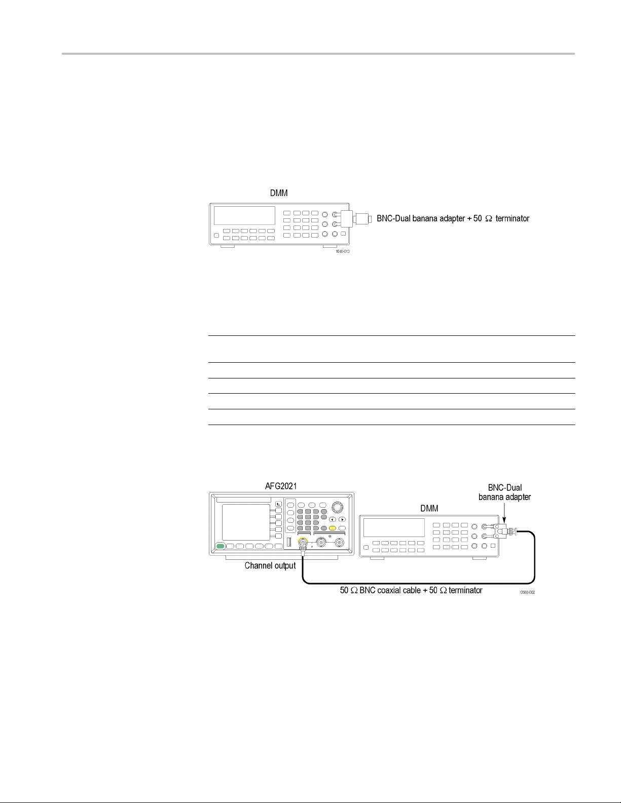
1. Connect the 50 Ω terminator to the DMM as shown in the following figure
and measure the register value.
Figure 3: 50 Ω terminator accuracy
2. Calculate the 50 Ω calibration factor (CF) from the reading value and record
as follows:
alibration Factor) = 2
CF (C
urement (reading of the DMM)
Meas
Ω
Examples
50.50 Ω 1.0050 (= 2 / (1 + 50 / 50.50))
49.62 Ω 0.9962 (= 2 / (1 + 50 / 49.62))
/ (1 + 50 Ω / Measurement Ω)
CF
AFG2021 Arbitrary Function Generator Specifications and Performance Verification 23
Page 34

Performance verification
3. Connect the arb
itrary function generator to the DMM as shown in the
following figure. Be sure to connect the 50 Ω terminator to the arbitrary
function generator Output connector side.
Figure 4: Amplitude tests
4. Set up the arbitrary function generator as follows:
a. Push the Sine button on the front panel.
b. Push the Frequency/Period/Phase Menu bezel button.
c. Push the Frequency bezel button (it will turn dark when activated) and
use the numeric keypad or general purpose knob to set the frequency to
1.000000 kHz.
d. Push the
button on the front panel to return to the top menu.
e. Push the Amplitude/Level Menu bezel button.
f. Push the -more- bezel button.
g. Push the Units Vpp bezel button and then push the Vrms bezel button
to change the voltage units to rms.
h. Check that the Channel On/Off front panel button LED is lit.
If it is not lit, then the channel output is o ff. Push the Channel On/Off
button to turn it on.
5. Verify that each amplitude measurement is within the range specified in the
following table.
Function Frequency Amplitude Measurement Range
Sine
Sine
Sine
Sine
Sine
Sine
Sine
1.000 kHz 30.0 mVrms mVrms
1.000 kHz 300.0 mVrms mVrms
1.000 kHz 800.0 mVrms mVrms
1.000 kHz 1.500 Vrms Vrms
1.000 kHz 2.000 Vrms Vrms
1.000 kHz 2.500 Vrms Vrms
1.000 kHz 3.500 Vrms Vrms
(30.0 × CF ± 0.654) mVrms
(300.0 × CF ± 3.35) mVrms
(800.0 × CF ± 8.35) mVrms
(1.500 × CF ± 0.0154) Vrms
(2.000 × CF ± 0.0204) Vrms
(2.500 × CF ± 0.0254) Vrms
(3.500 × CF ± 0.0354) Vrms
24 AFG2021 Arbitrary Function Generator Specifications and Performance Verification
Page 35
DC offset test
Performance verification
This test verifies the DC offset accuracy of the arbitrary function generator.
This test uses a 50 Ω terminator. It is necessa ry to know the accuracy of a 50 Ω
terminator i
n advance of this test. This accuracy is used as a calibration factor.
1. Connect the 50 Ω terminator to the DMM as shown in the following figure
and measure the register value.
Figure 5: 50 Ω terminator accuracy
2. Calculate the 50 Ω calibration factor (CF) from the reading value and record
as follows:
2
CF (Calibration Factor) =
Measurement (reading of t
DMM)
Ω
Examples
50.50 Ω 1.0050 (= 2 / (1 + 50 / 50.5
49.62 Ω 0.9962 (= 2 / (1 + 50 / 49.
/ (1 + 50 Ω / Measurement Ω)
he
CF
0))
62))
3. Connect the arbitrary function generator to the DMM as shown in the
following figure. Be sure to connect the 50 Ω terminator to the arbitrary
function generator Output connector side.
Figure 6: DC offset tests
4. Set up the arbitrary function generator as follows:
a. Push the More waveform button on the front panel.
b. Push the More Waveform Menu bezel button.
c. Push the DC bezel button.
AFG2021 Arbitrary Function Generator Specifications and Performance Verification 25
Page 36

Performance verification
Function
DC
DC
DC
Offset
+ 5.000 Vdc Vdc
0.000 Vdc Vdc ± 0.005 Vdc
- 5.000 Vdc Vdc
AC flatness test
d. Push the button
on the front panel to return to the top menu.
e. Push the Amplitude/Level Menu bezel button.
f. Push the Offset bezel button and use the numeric keypad or general
purpose knob to set the of fset value.
g. Check that the Channel On/Off front panel button LED is lit. If it is
not lit, then the channel output is off. Push the Channel On/Off button
to turn it on.
5. Verify that each offset measurement is within the range specified in the
following table.
Measurement Range
(5.000 × CF ± 0.055) Vdc
(- 5.000 × CF ± 0.055) Vdc
This test verifies the flatnessofasinewaveto100kHzsinewave.
1. Connect the arbitrary function generator to the power meter with a power
head as shown in the following figure.
Figure 7: AC flatness tests
2. Set up the arbitrary function generator as follows:
a. Push the Sine button on the front panel.
b. Push the Frequency/Period/Phase Menu bezel button.
c. Push the Frequency bezel button (it will turn dark when activated) and
use the numeric keypad or general purpose knob to set the frequency to
100.0000 kHz.
d. Push the
button on the front panel to return to the top menu.
26 AFG2021 Arbitrary Function Generator Specifications and Performance Verification
Page 37

Performance verification
e. Push the Amplit
ude/Level Menu bezel button.
f. Push the -more- bezel button.
g. Push the Units bezel button and then push the dBm bezel button to change
the voltage units to dBm.
h. Push the -more- bezel button.
i. Push the Amplitude bezel button (it will turn dark when activated) and
use the numeric keypad or general purpose knob to set the amplitude to
+4.0 dBm.
j. Check that the Channel On/Off front panel button LED is lit.
If it is not lit, then the channel output is off. Push the Channel On/Off
buttontoturniton.
3. Set the frequency of the Power Meter to 100 kHz.
4. Write the Power Meter reading of the 100 kHz sine w ave as a reference
power value.
5. Verify that the power measurement at each frequency is within the error
specified in the following table.
Function Amplitude Frequency
Sine
Sine
Sine
Sine
Sine
Sine
+ 4.0 dBm 100.00 kHz
+ 4.0 dBm 500.00 kHz
+ 4.0 dBm 1.00 MHz
+ 4.0 dBm 5.00 MHz
+ 4.0 dBm 10.00 MHz
+ 4.0 dBm 20.00 MHz
Measurement Range
(dB) (dB)
= Reference
------
Reference ± 0.15
Reference ± 0.15
Reference ± 0.30
Reference ± 0.30
Reference ± 0.30
AFG2021 Arbitrary Function Generator Specifications and Performance Verification 27
Page 38

Performance verification
Harmonics distortion test
This test verifies the harmonic distortion using a spectrum analyzer.
1. Connect the arbitrary function generator to the spectrum analyzer as shown in
the following figure.
Figure 8: Harmonic distortion tes
2. Push the following buttons to recall the arbitrary function generator default
setup:
Save/Recall > Setup > Recall > Default.
3. Set up the arbitrary function generator as follows:
a. Push the Sine button on the front panel.
b. Push the Frequency/Period/Phase Menu bezel button.
c. Push the Frequency bezel button (it will turn dark when activated) and
use the numeric keypad or general purpose knob to set the frequency to
20.00 kHz.
d. Push the
e. Push the Amplitude/Level Menu bezel button.
f. Push the -more- bezel button.
g. Push the Units bezel button and then push the Vpp bezel button to change
the voltage units to Vpp.
h. Push the -more- bezel button.
i. Push the Amplitude bezel button (it will turn dark when activated) and
use the numeric keypad or general purpose knob to set the amplitude
to 1.00 Vpp.
button on the front panel to return to the top menu.
ts
j. Check that the Channel On/Off front panel button LED is lit.
If it is not lit, then the channel output is o ff. Push the Channel On/Off
button to turn it on.
28 AFG2021 Arbitrary Function Generator Specifications and Performance Verification
Page 39
Performance verification
4. Set up the spect
rum analyzer according the frequency setup of the arbitrary
function generator.
5. Set the Ref Lev
el of the spectrum analyzer to 8 dBm.
6. Read the signal level in the Fundamental frequency for each signal. Use this
level as a Re
ference value in step 4.
7. Verify that the differences between the reference level and the signal level in
the frequen
cy of higher-order at each frequency are below the limit specified
in the following table.
Spectrum Analyzer Measurement Limit
Frequency
20.00 kHz 100 kHz 200 kHz 500 Hz 20 kHz 40 kHz 60 kHz 80 kHz 100 kHz < -60 dBc
100.00 kHz 500 kHz 1 MHz 2 kHz 100 kHz 200kHz 300 kHz 400 kHz 500 kHz < -60 dBc
1.00 MHz 5.00 MHz 10 MHz 20 kHz 1 MHz 2 MHz 3 MHz 4 MHz 5 MHz < -50 dBc
20.00 MHz 100MHz 200 MHz 20 kHz 20 MHz 40 MHz 60 MHz 80MHz 100 MHz < -40 dBc
Center
Frequency
Span
RBW Fundamental
(= Reference)
2nd 3rd 4th 5th Nth -
Reference
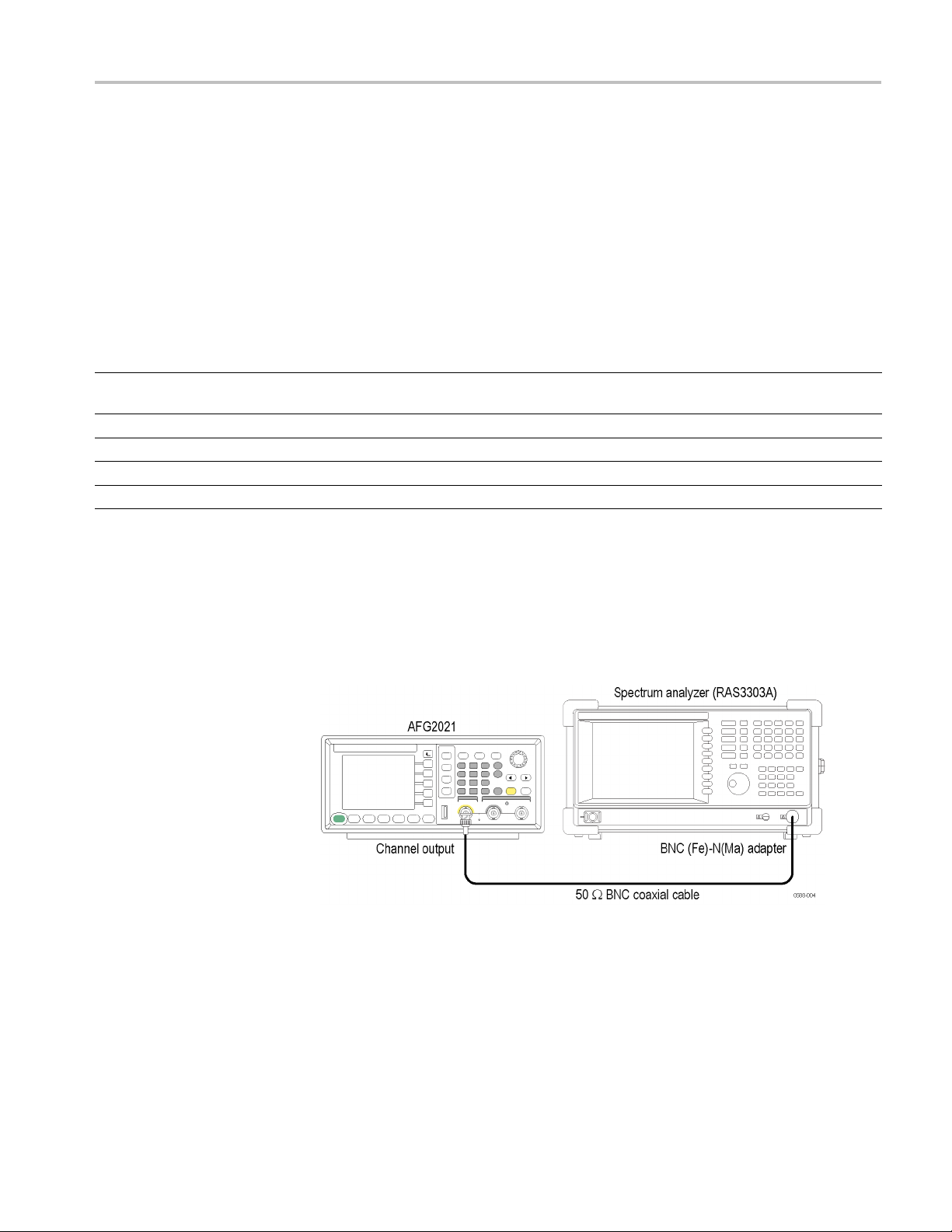
Total harmonic distortion test
This test verifies the total harmonic distortion (THD) using a spectrum analyzer.
1. Conne
ct the arbitrary function generator to the spectrum analyzer as shown in
the following figure.
Figure 9: Total harmonic distortion tests
2. Set up the arbitrary function generator as follows:
a. Push the Sine button on the front panel.
b. Push the Frequency/Period/Phase Menu bezel button.
AFG2021 Arbitrary Function Generator Specifications and Performance Verification 29
Page 40
Performance verification
c. Push the Freque
ncy bezel button (it will turn dark when activated) and
use the numeric keypad or general purpose knob to set the frequency to
20.00 kHz.
d. Push the
button on the front panel to return to the top menu.
e. Push the Amplitude/Level Menu bezel button.
f. Push the -more- bezel button.
g. Push the Units bezel button and then push the Vpp bezel button to change
the voltage units to Vpp.
h. Push the -more- bezel button.
i. Push the Amplitude bezel button (it will turn dark when activated) and
use the numeric keypad or general purpose knob to set the amplitude
to 1.00 Vpp.
j. Check that the Channel On/Off front panel button LED is lit.
If it is not lit, then the channel output is o ff. Push the Channel On/Off
button to turn it on.
3. Set up the spectrum analyzer according to the following table:
Center Frequency Span RBW
100 kHz 200 kHz 500 Hz
4. Set the Ref Level of the spectrum analyzer to 8 dBm.
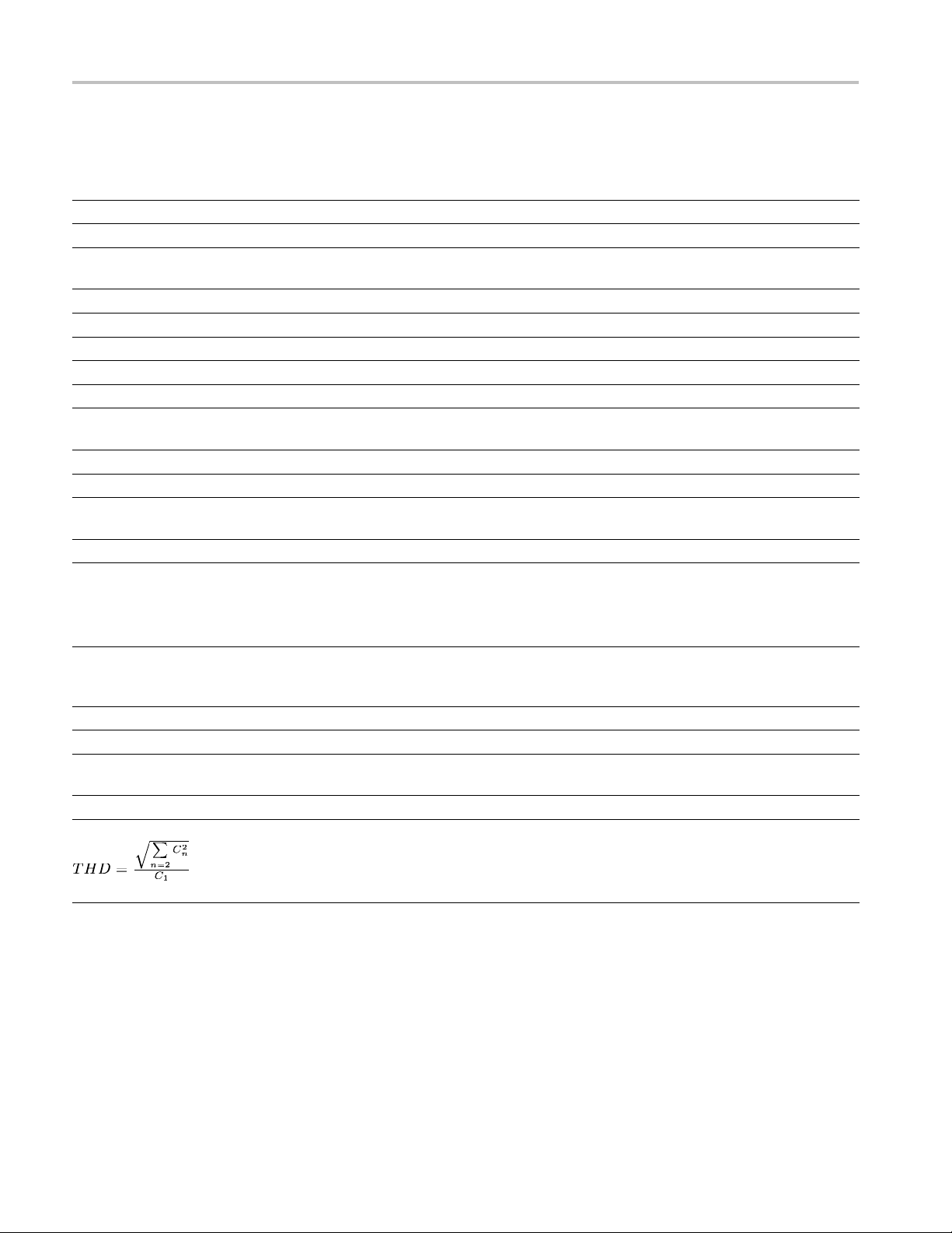
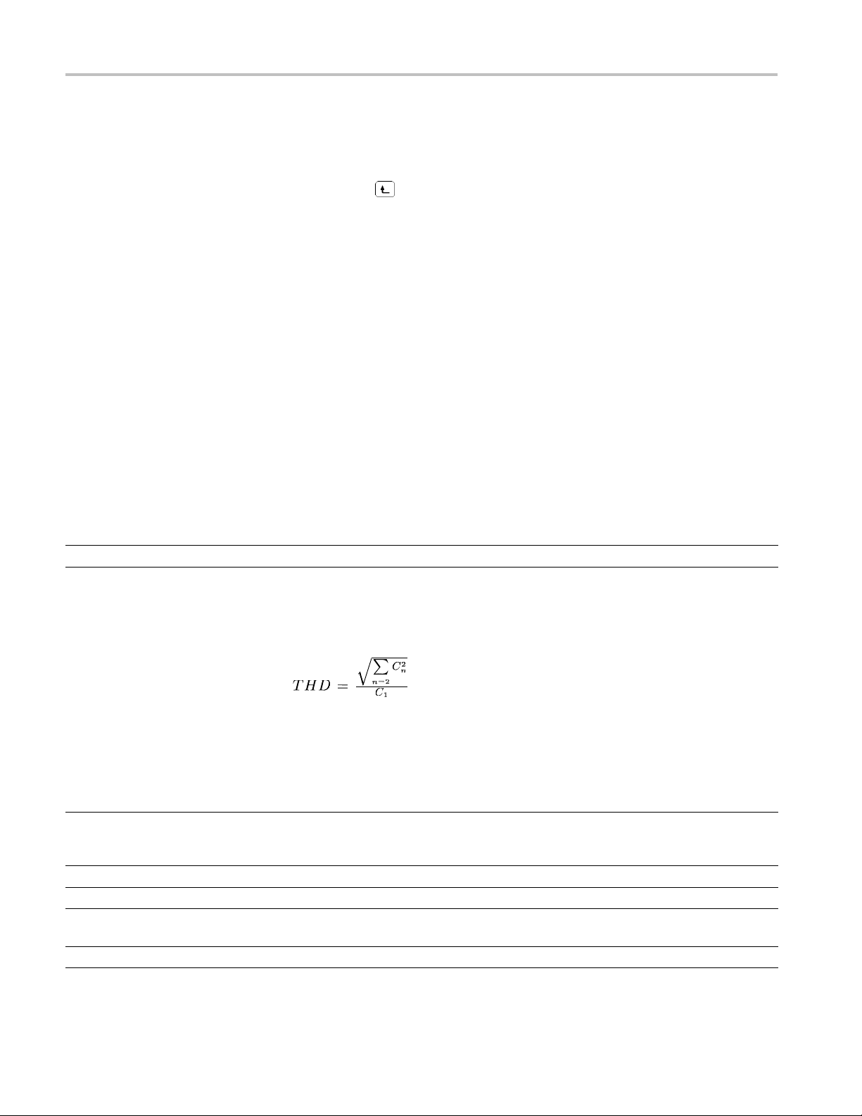
5. When the THD cannot be measured directly, it is obtained by using the
following calculation:
6. Measure and record each level (A1 to A7) to the seventh harmonics of the
20 kHz sine wave.
7. Calculate the each B1 to B7, C1 to C7 value and the THD.
Measurement
Function Frequency Fundamental
=
reference
sine 20.00 kHz 20 kHz 40 kHz 60 kHz 80 kHz 100 kHz 120 kHz 140 kHz
reading (dBm)
reading - reference Bn =
An - A1 (dBc)
Cn = 10 Bn/20 C1 = 1 C2 = C3 = C4 = C5 = C6 = C7 =
A1=A2=A3=A4=A5=A6=A7=
B1 = 0 B2 = B3 = B4 = B5 = B6 = B7 =
2nd 3rd 4th 5th 6th 7th
30 AFG2021 Arbitrary Function Generator Specifications and Performance Verification
Page 41
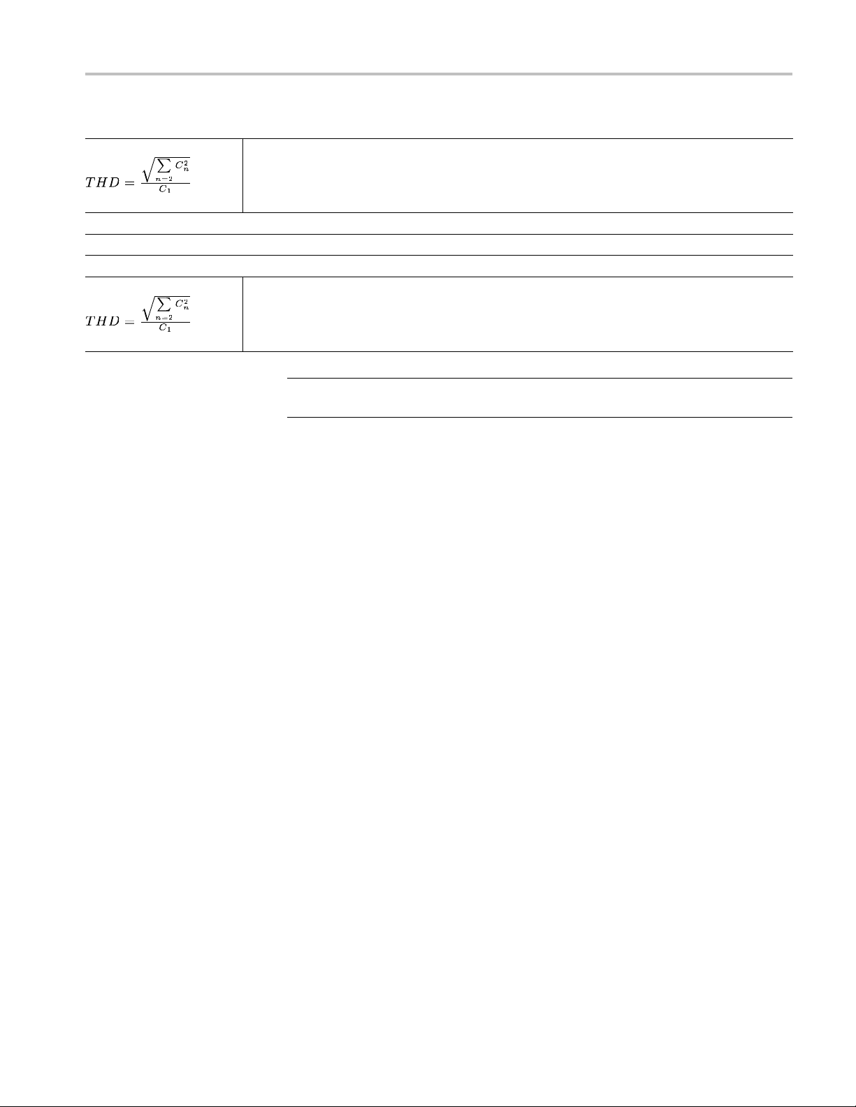
Performance verification
Measurement
THD = Limit
<0.2%
Sample: reading
reading - reference
Cn =
1.5 dBm -58.5 dBm -58.5 dBm -63.5 dBm -58.5 dBm -63.5 dBm -63.5 dBm
0 -60 dBm -60 dBm -65 dBm -60 dBm -65 dBm -65 dBm
1.000 0.001 0.001 0.000562 0.001 0.000562 0.000562
0.1987%
Limit
<0.2%
NOTE. When all the harmonic components are -62 dBm or less, the calculation
of THD can be ski
pped because it is THD < 0.2%.
8. Verify that the THD is less than 0.2%.
AFG2021 Arbitrary Function Generator Specifications and Performance Verification 31
Page 42

Performance verification
Spurious test
This test verifies the spurious using a spectrum analyzer.
1. Connect the arbitrary function generator to the spectrum analyzer as shown in
the following figure.
Figure 10: Spurious tests
2. Set up the arbitrary function generator as follows:
a. Push the Sine button on the front panel.
b. Push the Frequency/Period/Phase Menu bezel button.
c. Push the Frequency bezel button (it will turn dark when activated) and
use the numeric keypad or general purpose knob to set the frequency
to 100.00 kHz.
d. Push the
e. Push the Amplitude/Level Menu bezel button.
f. Push the -more- bezel button.
g. Push the Units bezel button and then push the Vpp bezel button to change
the voltage units to Vpp.
h. Push the -more- bezel button.
i. Push the Amplitude bezel button (it will turn dark when activated) and
use the numeric keypad or general purpose knob to set the amplitude
to 1.00 Vpp.
j. Check that the Channel On/Off front panel button LED is lit.
If it is not lit, then the channel output is o ff. Push the Channel On/Off
button to turn it on.
button on the front panel to return to the top menu.
3. Set the center frequency of the spectrum analyzer to 10 MHz. Other settings
are shown in the following table.
4. Set the Ref Level of the spectrum analyzer to 8 dBm.
32 AFG2021 Arbitrary Function Generator Specifications and Performance Verification
Page 43

Performance verification
Spectrum analyzer Measurement
Frequency
100.00 kHz 10 M Hz
1.00 MHz 10 MHz
10.00 MHz 10 MHz
20.00 MHz 10 MHz
Center
Frequency
300 MHz
300 MHz
300 MHz
300 MHz
5. Measure the max
imum spurious level other than harmonic distortion of 1 Vpp
sine wave in each frequency.
6. Set the center
frequency of the spectrum analyzer to 300 MHz. Other settings
are shown in the following table.
7. Measure the
maximum spurious level other than harmonic distortion of 1 Vpp
sine wave in each frequency.
8. Verify that
the spurious signal at each frequency is equal to or less than the
limit specified in the following table.
Span
20 MHz
600 MHz
20 MHz
600 MHz
20 MHz
600 MHz
20 MHz
600 MHz
RBW
20 kHz
20 kHz
20 kHz
20 kHz
20 kHz
20 kHz
20 kHz
20 kHz
Spurious
Frequency
MHz
MHz
MHz
MHz
MHz
MHz
MHz
MHz
Spurious
(Max)
dBc
dBc
dBc
dBc
dBc
dBc
dBc
dBc
Limit
< -60 dBc
< -50 dBc
< -50 dBc
< -50 dBc
AFG2021 Arbitrary Function Generator Specifications and Performance Verification 33
Page 44

Performance verification
Rise-Fall time test
This test verifies the pulse rise time of the arbitrary function generator.
1. Connect the arbitrary function generator to the oscilloscope as shown in the
following figure.
Figure 11: Rise-Fall time tests
2. Set up the arbitrary function generator as follows:
a. Push the Square button on the front panel.
b. Push the Frequency/Period/Phase Menu bezel button.
c. Push the Frequency bezel button (it will turn dark when activated) and
use the numeric keypad or general purpose knob to set the frequency
to 10.00 MHz.
d. Push the
e. Push the Amplitude/Level Menu bezel button.
f. Push the -more- bezel button.
g. Push the Units bezel button and then push the Vpp bezel button to change
the voltage units to Vpp.
h. Push the -more- bezel bu
i. Push the Amplitude bezel button and use the numeric keypad or gene
purpose knob to set the amplitude to 1.00 Vpp.
j. Push the Offset bezel button and use the numeric keypad or general
purpose knob to set the value to 0.0 mV.
button on the front panel to return to the top menu.
tton.
ral
k. Check that the Channel On/Off front panel button LED is lit. If it is
not lit, then the channel output is off. Push the Channel On/Off button
to turn it on.
34 AFG2021 Arbitrary Function Generator Specifications and Performance Verification
Page 45

Performance verification
Function Frequency
Square
Square
10.00 MHz 0.0 V 1.0 Vpp
10.00 MHz 0.0 V 10.0 Vpp
3. Set up the Oscil
loscope so the square waveform of 5 division amplitude is
displayed.
4. Verify that th
e rise/fall time of the square waveform on the oscilloscope at
each amplitude is equal to or less than the limit specified in the following
table. Use 10-90% refe r ence level for rise/fall time m easurement.
pe
v
5ns/div
Measuremen
≤ 18 ns
≤ 18 ns
Offset
Oscillosco
Amplitude Vertical Horizontal Limit
200 mV/div 5 ns/div
200 mV/di
with x10
attenuator
t
AFG2021 Arbitrary Function Generator Specifications and Performance Verification 35
 Loading...