

Page 1

AFG1022
Arbitrary Function Generator
Programmer Manual
*P077105700*
077-1057-00
Page 2

AFG1022
Arbitrary Function Generator
Programmer Manual
www.tektronix.com
077-1057-00
Page 3

Copyright © Tektronix. All rights reserved. Licensed software products are owned by Tektronix or its subsidiaries
or suppliers, and are protected by national copyright laws and international treaty provisions.
Tektronix products are covered by U.S. and foreign patents, issued and pending. Information in this publication
supersedes that in all previously published material. Specifications and price change privileges reserved.
TEKTRONIX and TEK are registered trademarks of Tektronix, Inc.
Contacting Tektronix
Tektronix, Inc.
14150 SW Karl Braun Drive
P.O. Box 500
Beaverton, OR 97077
USA
For product information, sales, service, and technical support:
In North America, call 1-800-833-9200.
Worldwide, visit www.tektronix.com to find contacts in your area.
Page 4

Warranty
Tektronix warrants that the product will be free from defects in materials and workmanship for a period of three (3)
years from the date of original purchase from an authorized Tektronix distributor. If the product proves defective
during this warranty period, Tektronix, at its option, either will repair the defective product without charge for parts
and labor, or will provide a replacement in exchange for the defective product. Parts, modules and replacement
products used by Tektronix for warranty work may be new or
parts, modules and products become the property of Tektronix.
In order to obtain service under this warranty, Customer must notify Tektronix of the defect before the expiration
of the warranty period and make suitable arrangements for the performance of service. Customer shall be
responsible for packaging and shipping the defective product to the service center designated by Tektronix,
shipping charges prepaid, and with a copy of customer proof of purchase. Tektronix shall pay for the return of the
product to Customer if the shipment is to a location within the country in which the Tektronix service center is
located. Customer shall be responsible for paying all shipping charges, duties, taxes, and any other charges for
products returned to any other locations.
This warranty shall not apply to any defect, failure or damage caused by improper use or improper or inadequate
maintenance and care. Tektronix shall not be obligated to furnish service under this warranty a) to repair damage
resulting from attempts by personnel other than Tektronix representatives to install, repair or service the product;
b) to repair damage resulting from improper use or connection to
or malfunction caused by the use of non-Tektronix supplies; or d) to service a product that has been modified or
integrated with other products when the effect of such modification or integration increases the time or difficulty of
servicing the product.
reconditioned to like new performance. All replaced
incompatible equipment; c) to repair any damage
THIS WARRANTY IS GIVEN BY TEKTRONIX WITH RESPECT TO THE PRODUCT IN LIEU OF ANY
OTHER WARRANTIES, EXPRESS OR IMPLIED. TEKTRONIX AND ITS VENDORS DISCLAIM ANY
IMPLIED WARRANTIES OF MERCHANTABILITY OR FITNESS FOR A PARTICULAR PURPOSE.
TEKTRONIX' RESPONSIBILITY TO REPAIR OR REPLACE DEFECTIVE PRODUCTS IS THE SOLE AND
EXCLUSIVE REMEDY PROVIDED TO THE CUSTOMER FOR BREACH OF THIS WARRANTY.
TEKTRONIX AND ITS VENDORS WILL NOT BE LIABLE FOR ANY INDIRECT, SPECIAL, INCIDENTAL,
OR CONSEQUENTIAL DAMAGES IRRESPECTIVE OF WHETHER TEKTRONIX OR THE VENDOR HAS
ADVANCE NOTICE OF THE POSSIBILITY OF SUCH DAMAGES.
[W2 – 15AUG04]
Page 5

AFG1022 Arbitrary Function Generator Programmer Manual
i
Table of contents
Getting Started ....................................................................................................................................... 1
Introduction ...................................................................................................................................... 1
Connecting the Interface ............................................................................................................ 1
Using TekVISA ......................................................................................................................... 1
Where to find more information ................................................................................................ 2
Syntax and Commands ........................................................................................................................... 3
Command Syntax ............................................................................................................................. 3
Backus-Naur Form Definition ................................................................................................... 3
Command and Query Structure ................................................................................................. 3
SCPI Commands and Queries .................................................................................................... 5
IEEE 488.2 Common Commands .............................................................................................. 9
Command Groups ......................................................................................................................... 10
Command Descriptions................................................................................................................. 13
*CLS (No Query Form) ........................................................................................................... 13
*IDN? (Query Only) ................................................................................................................ 13
MMEMory:CATalog? (Query Only) ....................................................................................... 14
MMEMory:CDIRectory ........................................................................................................... 15
MMEMory:DELete (No Query Form) ...................................................................................... 16
*OPT? (Query Only) ............................................................................................................... 16
OUTPut[1|2][:STATe] .............................................................................................................. 17
*RST (No Query Form) ............................................................................................................ 17
[SOURce1]:AM:STATe ........................................................................................................... 18
[SOURce1]:BURSt:MODE ..................................................................................................... 18
[SOURce1]:BURSt:NCYCles ................................................................................................. 19
[SOURce1]:BURSt:STATe ...................................................................................................... 19
[SOURce1]:FM:STATe
[SOURce[1|2]]:FREQuency:CONCurrent[:STATe] ............................................................... 20
[SOURce[1|2]]:FREQuency[:CW|:FIXed] .............................................................................. 21
[SOURce1]:FREQuency:MODE ............................................................................................. 22
[SOURce1]:FSKey:STATe ...................................................................................................... 23
[SOURce[1|2]]:FUNCtion:EFILe ............................................................................................ 23
[SOURce[1|2]]:FUNCtion[:SHAPe] ....................................................................................... 24
[SOURce[1|2]]:PHASe[:ADJust] ............................................................................................ 25
[SOURce1]:PM:STATe
[SOURce[1|2]]:VOLTage[:LEVel][:IMMediate]:OFFSet ........................................................ 26
[SOURce[1|2]]:VOLTage[:LEVel][:IMMediate][:AMPLitude] .............................................. 27
SYSTem:ERRor[:NEXT]? (Query Only) ................................................................................. 28
TRACe|DATA:CATalog? (Query Only) .................................................................................. 29
.............................................................................................................. 20
............................................................................................................. 26
Page 6

Table of Contents
ii
AFG1022 Arbitrary Function Generator Programmer Manual
TRACe|DATA:COPY (No Query Form) .................................................................................29
TRACe|DATA[:DATA] ............................................................................................................30
TRACe|DATA[:DATA]:VALue ................................................................................................30
TRACe|DATA:POINts .............................................................................................................31
*WAI (No Query Form) ...........................................................................................................32
Command Errors...................................................................................................................................33
Index .....................................................................................................................................................34
Page 7

AFG1022 Arbitrary Function Generator Programmer Manual
1
AC line
connector
USB
(
type
B
)
connector
Getting Started
Introduction
This programmer g uide provides inform ation to use commands for remotely
controlling your instru ment. With this in formation, write computer programs that will
perform functions such as setting the front-panel controls, selecting clock source,
setting sampling rate , and exporting data for use in other programs.
Connecting the Interface
The AFG1022 has a USB (type B) connector on the rear panel, as shown in the
following figure. This connector conforms to USB-TMC. Attach a USB cable to
this connector.
Figure 1: USB (type B) connector
Using TekVISA
TekVISA is Tektronix implementation of VISA (Virtual Instrument Software
Architecture), an industry-standard communication protocol. VISA provides
a common standard for software developers so that software from multiple
vendors, such as instrument drivers, can run on the same platform. TekVISA is
industry-compliant software, available with selected Tektronix instruments.
You can use this software to write (or draw) interoperable instrument drivers in
a variety of Application Development Environments (ADEs). It implements a
subset of Version 2.2 of the VISA specification for controlling USB
instrument interface locally.
Page 8

2
AFG1022 Arbitrary Function Generator Programmer Manual
Getting Started
Item
Purpose
Location
Important
safety and
compliance
instructions
Compliance and
safety instructions
Built-in
Help
UI Help and
Operation
Quick Start
User
Unpacking, Installation,
T
and
Programmer
Manu
Menu Structures,
User
Interface,
and
Information
Technical
Reference
Specifications
and
performance
ver
Installation
Use an internet browser to access the Tektronix Web site (www.tektronix.com)
and download the current TekVISA to your PC. Unzip the downloaded file in
temporary directory of your choice and run Setup.exe.
a
NOTE: The details on TekVISA concepts and operations are explained in the
TekVISA Programmer Manual that can be also found on the Tektronix Web site.
Where to find more informati on
The following table lists related documentation available for your instrument.
The documentation is available on the Product Documentation CD and on the
Tektronix Web site (www.tektronix.com/manuals).
Manual
al
utorials, Operation,
Overviews
Programming
ification
procedures
Page 9

AFG1022 Arbitrary Function Generator Programmer Manual
3
Syntax and Commands
Command Syntax
You can control the operations and functions of the instrument through the
USB interface using commands and queries. The related topics listed below
describe the syntax of these commands and queries. The topics also describe the
conventions that the instrument uses to process them. See Command Groups
(See page 10.) for a listing of the commands by command group, or use the
index to locate a specific command.
Backus-Naur Form Definition
This manual describes commands and queries using the Backus-Naur Form
(BNF) notation. The following table defines the standard BNF symbols.
Table 1: BNF symbols and meanings
Symbol
< >
:=
|
{ } Group; one element is required
[ ] Optional; can be omitted
. . .
( ) Comment
Meaning
Defined element
Is defined as
Exclusive OR
Previous element(s) may be repeated
Command and Query Structure
Overview
Messages
Commands consist of set commands and query commands (usually simply called
commands and queries). Commands change instrument settings or perform a
specific action. Queries cause the instrument to return data and information about
its status.
Most commands have both a set form and a query form. The query form of the
command is the same as
For example, the set command
MMEMory:CDIRectory?. Not all commands have both a set and a query form;
some commands are set only and some are query only.
A command message is a command or query name, followed by any
information the instrument needs to execute the command or query. Command
messages consist of five element types.
the set form except that it ends with a question mark.
MMEMory:CDIRectory has a query form
Page 10

4
AFG1022 Arbitrary Function Generator Programmer Manual
Command Syntax
Table 2: Command message elements
Symbol
<Header>
Meaning
The basic command name. If the header ends with a question mark, the
command is a query. The header may begin with a colon (:) character; if
the comman
d is concatenated with other commands the beginning
is required. The beginning colon can never be used with command
<Mnemonic>
headers beginning with a star (*).
A header subfunction. Some command headers have only one mnemonic.
If a command
from each other by a colon (:) character.
header has multiple mnemonics, they are always separated
<Argument> A quantity, quality, restriction, or limit associated with the header. Not
all commands have an argument, while other commands have multiple
arguments. Arguments are separated from the header by a <Space>.
Arguments are separated from each other by a <Comma>.
<Comma> A single comma between arguments of multiple-argument commands. It
may optionally have white space characters before and after the comma.
<Space> A white space character between command header and argument. It may
optionally consist of multiple white space characters.
colon
Commands
Commands cause the instrument to perform a specific function or change one of
its settings. Commands have the structure:
[:]<Header>[<Space><Argument>[<Comma><Argument>]...]
A command header is made up of one or more mnemonics arranged in a
hierarchical or tree structure. The first mnemonic is the base or root of the tree and
each subsequent mnemonic is a level or branch of the previous one. Commands at
a higher level in the tree may affect those at a lower level. The leading colon (:)
always returns you to the base of the command tree.
Queries
Query Responses
Queries cause the instrument to return information about its status or settings.
Queries have the structure:
[:]<Header>?
[:]<Header>?[<Space><Argument>[<Comma><Argument>]...]
Specify a query command at any level within the command tree unless
otherwise noted. These branch queries return information about all the mnemonics
below the specified branch or level.
When a query is sent to the instrument, only the values are returned. When the
returned value is a mnemonic, it is noted in abbreviated format.
Page 11

AFG1022 Arbitrary Function Generator Programmer Manual
5
Command Syntax
Command Entry
Follow these general rules when entering commands:
Enter commands in upper or lower case.
Precede any command with white space characters. White space
include any combination of the ASCII control characters 00 through
0B through 20 hexadecimal (0 through 9 and 11 through 32 decimal).
The instrument ignores commands that consists of just a combination of white
space characters and line feeds.
SCPI Commands and Queries
The instrument uses a command language based on the SCPI standard. The SCPI
(Standard Commands for Programmable Instruments) standard was created by a
consortium to provide guidelines for remote programming of instruments.
These guidelines provide a consistent programming environment for instrument
control and data transfer. This environment uses defined programming messages,
instrument responses and data formats that operate across all SCPI instruments,
regardless of manufacturer.
The SCPI language is based on a hierarchical or tree structure. The top level of
the tree is the root
You can create commands and queries from these subsystem hierarchy trees.
Commands specify actions for the instrument to perform. Queries return
measurement data and information about parameter settings.
Creating Commands
SCPI commands are created by stringing together the nodes of a subsystem
hierarchy and separating each node by a colon.
node; it is followed by one or more lower-level nodes.
characters
09 and
To create a SCPI command, start with the root node and move down the tree
structure adding nodes until you reach the
some queries have parameters; you must
you specify a parameter value that is out
default value. The command descriptions,
parameters.
Creating Queries
Query Responses
Parameter Types
To create a query, start at the root node of a tree structure, move down to the end of
a branch, and add a question mark.
The query causes the instrument to return information about its status or settings.
When a query is sent to the instrument, only the values are returned. When the
returned value is a mnemonic, it is noted in abbreviated format.
Every parameter in the command and query descriptions is of a specified type.
(See Table 3.) The parameters are enclosed in brackets, such as <value>.
end of a branch. Most commands and
include a value for these parameters. If
of range, the parameter will be set to a
list the valid values for all
Page 12

6
AFG1022 Arbitrary Function Generator Programmer Manual
Command Syntax
Parameter type
Description
Example
arbitrary block
1
A specified length of
arbitrary
#512234xxxxx . . . where
5
5
length
xxxxx
#0xxxxx...<LF><&EOI>
boolean
Boolean numbers or values
ON or ≠ 0
OFF or 0
discrete
A list of specific values
MIN, MAX
binary
Binary numbers
#B0110
octal
Octal numbers
#Q57, #Q3
hexadecimal
2
Hexadecimal numbers
(0-9, A, B, C, D, E, F)
#H AA, #H1
NR1 2 numeric
Integers
0, 1, 15, -1
NR2
2 3
numeric
Decimal numbers
1.2, 3.141516, -6.5
NR3 2 numeric
Floating point numbers
3.1415E-9, -16.1E5
NRf 2 numeric
Flexible decimal number that
may be type NR1, NR2 or NR3
See NR1, NR2, and NR3
examples
string
4
Alphanumeric characters (must
be within quotation marks)
"Testing 1, 2, 3"
The parameter type is listed after the parameter and is enclosed in parentheses,
for example, (boolean). Some parameter types are defined specifically for the
instrument command set and some are defined by SCPI.
Table 3: Parameter types used in syntax descriptions
data
indicates that the following
digits (12234) specify the
of the data in bytes;
... indicates the data
or
1
Defined in ANSI/IEEE 488.2 as "Definite Length Arbitrary Block Response Data."
2
An ANSI/IEEE 488.2-1992-defined parameter type.
3
Some commands and queries will accept an octal or hexadecimal value even though the parameter type is
defined as NR1.
4
Defined in ANSI/IEEE 488.2 as "String Response Data."
Special Characters
The Line Feed (LF) character or the New Line (NL) character (ASCII 10), and all
characters in the range of ASCII 127-255 are defined as special characters. These
characters are used in arbitrary block arguments only; using these characters in
other parts of any command yields unpredictable results.
Page 13
AFG1022 Arbitrary Function Generator Programmer Manual
7
Command Syntax
Abbreviating Commands,
Queries, and Parameters
Chaining Commands and
Queries
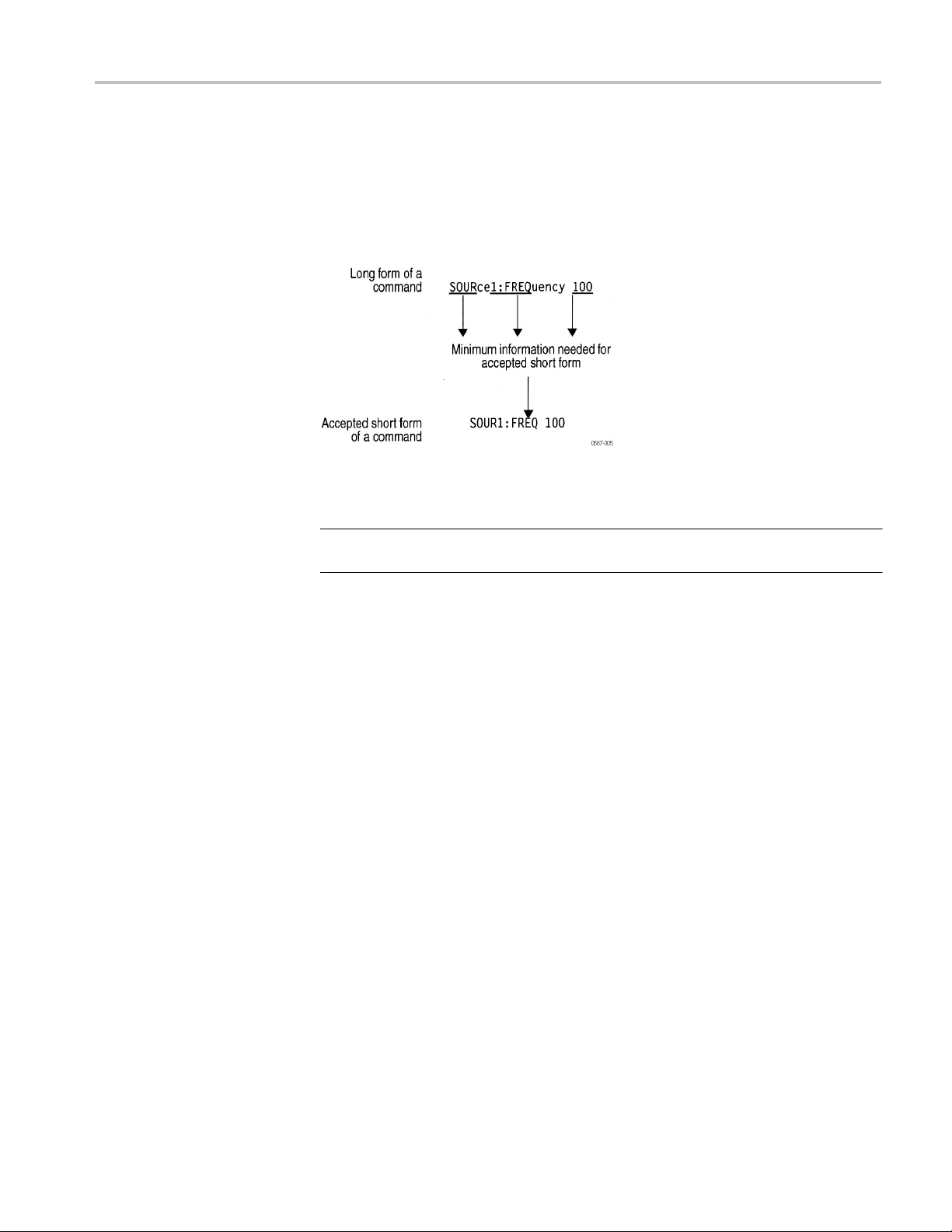
You can abbreviate most SCPI commands, queries, and parameters to an accepted
short form. This manual shows these short forms as a combination of upper and
lower case letters. The upper case letters indicate the accepted short form of a
command. As shown in the following figure, create a short form by using only
the upper case letters. The accepted short form and the long form are
equivalent
and request the same action of the instrument.
Figure 2: Example of abbreviating a command
NOTE: The numeric suffix of a command or query may be included in either the
long form or short form; the instrument will default to "1" if no suffix is used.
You can chain several commands or queries together into a single message. To
create a chained message, first create a command or query, add a semicolon (;),
and then add more commands or queries and semicolons until the message is
complete. If the command following a semicolon is a root node, precede it with
a colon (:).The single chained message should end in a
semicolon. Responses to any queries in your message
semicolons.
command or query, not a
are separated by
If a command or query has the same root and lower-level nodes as the previous
command or query, you can omit these nodes.
Unit and SI Prefix
If the decimal numeric argument refers to amplitude, frequency, or time, you can
express it using SI units instead of using the scaled explicit point input value
format <NR3>. (SI units are units that conform to the Systeme International
d'Unites standard.) For example, use the input format 200 mV or 1.0 MHz
instead of 200.0E-3 or 1.0E+6, respectively, to specify voltage or frequency.
Page 14

8
AFG1022 Arbitrary Function Generator Programmer Manual
Command Syntax
The following table lists the available units.
Table 4: Available units
General rules for using
SCPI commands
Symbol Meaning
DEG
degree (phase)
Hz hertz (frequency)
PCT
s
V
Vpp
percent (%)
second (time)
volt
volt
You can omit a unit in a command, but you must include the unit when using a SI
prefix. For example, frequency of 15 MHz can be described as follows
15.0E6, 1.5E7Hz, 15000000, 15000000Hz, 15MHz, etc.
("15M" is not allowed.)
Here are three general rules for using SCPI commands, queries, and parameters:
You can use single (‘ ’) or double (“ ”) quotation marks for quoted strings, but
cannot use both types of quotation marks for the same string.
correct
correct
"This string uses quotation marks correctly."
‘This
string also uses quotation marks correctly.'
you
incorrect
You can use upper case, lower case, or a mixture of both cases for all
"This
string does not use quotation marks correctly.'
commands,
queries, and parameters.
SOURCE1:FREQUENCY 10MHZ
is the same as
NOTE: Literal strings (quoted) are case sensitive, for example, file names.
source1:frequency 100mhz
and
SOURCE1:frequency 10MHZ
No embedded spaces are allowed between or within nodes.
correct
incorrect
SOURCE1:FREQUENCY 10MHZ
SOURCE1: FREQUENCY 10MHZ
Page 15

AFG1022 Arbitrary Function Generator Programmer Manual
9
Command Syntax
IEEE 488.2 Common Commands
Description
Command and Query
Structure
ANSI/IEEE Standard 488.2 defines the codes, formats, protocols, and usage of
common commands and queries used on the interface between the controller and
the instruments. The instrument complies with this standard.
The syntax for an IEEE 488.2 common command is an asterisk (*) followed by a
command and, optionally, a space and parameter value. The syntax for an IEEE
488.2 common query is an asterisk (*) followed by a query and a question mark.
All of the common commands and queries are listed in the last part of the Syntax
and Commands section. The following are examples of common commands:
*CLS
The following are examples of common queries
*IDN?
Page 16

10
AFG1022 Arbitrary Function Generator Programmer Manual
Command Groups
Mass Memory Commands
Output Commands
This section lists the commands organized by functional group. The Command
Descriptions section lists all commands alphabetically. (See page 13.)
Mass Memory commands let you change mass memory attributes. The
following table lists and describes the Mass Memory commands.
Table 5: Mass Memory commands
Command
MMEMory:CATalog?
MMEMory:CDIRectory
MMEMory:DELete
Description
Query the status of mass memory
Set/query current directory
Delete file or directory in mass memory
Output commands let you set output attributes. The following table lists and
describes the Output commands.
Table 6: Output commands
Command
OUTPut[1|2][:STATe]
Description
Set/query output on or off
Page 17

AFG1022 Arbitrary Function Generator Programmer Manual
11
Command Groups
Source Commands
Source commands let you set waveform output parameters. The following table
lists and describes the Source commands.
Table 7: Source commands
Command
[SOURce1]:AM:STATe
[SOURce1]:BURSt:MODE
[SOURce1]:BURSt:NCYCles
[SOURce1]:BURSt:STATe
[SOURce1]:FM:STATe
[SOURce[1|2]]:FREQuency:CONCurrent[:STATe]
[SOURce[1|2]]:FREQuency[:CW|:FIXed]
[SOURce1]:FREQuency:MODE
[SOURce1]:FSKey:STATe
[SOURce[1|2]]:FUNCtion:EFILe
[SOURce[1|2]]:FUNCtion[:SHAPe]
[SOURce[1|2]]:PHASe[:ADJust]
[SOURce1]:PM:STATe
[SOURce[1|2]]:VOLTage[:LEVel]
[:IMMediate]: OFFSet
[SOURce[1|2]]:VOLTage[:LEVel]
[:IMMediate][: AMPLitude]
Status Commands
Status commands let you determine the status of the instrument. The following
Description
Set/query amplitude modulation status
Set/query burst mode
Set/query burst mode waveform output cycle
Set/query burst mode status
Set/query frequency modulation status
Set/query concurrent change of frequency
Set/query output waveform frequency
Set/query sweep status
Set/query FSK status
Set/query EFILe name
Set/query output waveform
Set/query output waveform phase
Set/query phase modulation status
Set/query output offset voltage
output amplitude
Set/query
table lists and describes the Status commands.
Table 8: Status commands
Command
*CLS
System Commands
System commands let you control miscellaneous instrument functions. The
following table lists and describes the System commands.
Table 9: System commands
Command
*IDN?
*OPT?
*RST
SYSTem:ERRor[:NEXT]? Return error event queue
Description
Clear all event registers and queues
Description
Return identification information
Return option information
Reset
Page 18

12
AFG1022 Arbitrary Function Generator Programmer Manual
Command Groups
Synchronization Commands
Synchronization commands let you synchronize the operation of the
instrument. The following table lists and describes the
Synchronization
commands.
Table 10: Synchronization commands
Command
*WAI Wait to continue
Description
Trace Commands
Trace commands let you set the edit memory and user waveform memory. The
following table lists and describes the Trace commands.
Table 11: Trace commands
Command
TRACe|DATA:CATalog?
TRACe|DATA:COPY
TRACe|DATA[:DATA] Set/query waveform data to edit memory
TRACe|DATA[:DATA]:VALue
TRACe|DATA:POINts Set/query number of points for waveform
Description
Return user waveform memory status
Copy edit memory (or user waveform
memory) content to user waveform memory
(or edit memory)
Set/quer
y waveform data in edit memory
data in edit memory
Page 19

AFG1022 Arbitrary Function Generator Programmer Manual
13
Command Descriptions
Manual Conventions
*CLS (No Query Form)
Group
Commands either set or query instrument values. Some commands both set and
query, some only set, and some only query.
This manual uses the following conventions:
No Query Form indicates set-only commands
A question mark (?) appended to the comman ds and Query Only indicates
query-only commands
Fully spells out headers, mnemonics, and arguments with the minimal
spelling shown in upper case; for example, to use the abbreviated form of the
DISPlay:BRIGhtness command, just type DISP:BRIG
Syntax of some commands varies, depending on the model of instrument
you are using; differences are noted
This command clears all the event registers and queues, which are used in the
instrument status and event reporting system.
Status
Syntax
Arguments
Examples
*IDN? (Query Only)
*CLS
None
*CLS
clears all the event registers and queues.
This query-only command returns identification information on the instrument.
Page 20

14
AFG1022 Arbitrary Function Generator Programmer Manual
Command Descriptions
Group
System
Syntax
*IDN?
None
Arguments
Returns
Examples
<Manufacturer>,<Model>,<Serial Number>,<Firmware Level>
where:
<Manufacturer>::=
<Model>::={AFG1022}
<Serial Number>
<Firmware Level>
*IDN?
might return the following response:
TEKTRONIX,AFG1022,1331030,V1.24
TEKTRONIX
MMEMory:CATalog? (Query Only)
This query-only command returns the current state of the mass storage system
(USB memory).
Group
Mass Memory
Syntax
MMEMory:CATalog?
Related Commands
MMEMory:CDIRectory
None
Arguments
Returns
<NR1>,<NR1>[,<file_name>,<file_type>,<file_size>]...
where:
Page 21

AFG1022 Arbitrary Function Generator Programmer Manual
15
Command Descriptions
The first <NR1> indicates that the total amount of storage currently used, in bytes.
The second <NR1> indicates that the free space of mass storage, in bytes.
<file_name> is the name of directory or file. If the name exceeds 22 characters in
length, it will be shortened to 8 characters (without suffix) in 8.3 name format.
<file_type> is DIR for directory, otherwise it is blank.
<file_size> is the size of the file, in bytes. This value will be 0 for directory.
Examples
The USB memory includes the Case and PWS4000-Main-CPU-Update folders, a
SAMPLE1.tfw file, and a Test.zip file. The directory name PWS4000-Main-CPUUpdate will be shortened to PWS400~1.
MMEMory:CATalog? might return the following response:
32751616,27970560,"Case,DIR,0","PWS400~1,DIR,0",”SAMPLE1.tfw,
,5412”,”Test.zip,,1735”
MMEMory:CDIRectory
Group
Syntax
Arguments
Returns
Examples
This command changes the current working directory in the mass storage system.
Mass Memory
MMEMory:CDIRectory [<directory_name>]
MMEMory:CDIRectory?
<directory_name>::=<string> indicates the current working directory for the
mass storage system.
<directory_name>::=<string>
MMEMory:CDIRectory ”/AFG/WORK0”
changes the current directory to /AFG/WORK0.
Page 22

16
AFG1022 Arbitrary Function Generator Programmer Manual
Command Descriptions
MMEMory:DELete (No Query Form)
Group
Syntax
Arguments
Examples
*OPT? (Query Only)
Group
Syntax
This command deletes a file or directory from the mass storage system. If a
specified file in the mass storage is not allowed to overwrite or delete, this
command causes an error. You can delete a directory if it is empty.
Mass Memory
MMEMory:DELete <file_name>
<file_name>::=<string> specifies a file to be deleted and should include full path.
MMEMory:DELete ”/AFG/WORK0/TEK001.tfw”
deletes the specified file from the /AFG/WORK directory.
This query-only command returns a list of the options installed in your instrument.
System
*OPT?
None
Arguments
Returns
<OPT>[,<OPT>[,<OPT>[,<OPT>]]]
Examples
*OPT?
might return 0, which indicates no option is installed in the instrument.
Page 23

AFG1022 Arbitrary Function Generator Programmer Manual
17
Command Descriptions
OUTPut[1|2][:STATe]
Group
Syntax
This command sets or query the instrument output state for the specified
channel.
Output
OUTPut[1|2][:STATe] {ON|OFF|<NR1>}
OUTPut[1|2][:STATe]?
Arguments
Returns
Examples
*RST (No Query Form)
Group
Syntax
ON or <NR1>≠0 enables the instrument output.
OFF or <NR1>=0 disables the instrument output.
<NR1>
OUTPut1:STATe ON
sets the instrument CH 1 output to ON.
This command resets the instrument to the factory default settings.
System
*RST
None
Arguments
Examples
*RST
resets the instrument settings to the factory defaults.
Page 24

18
AFG1022 Arbitrary Function Generator Programmer Manual
Command Descriptions
[SOURce1]:AM:STATe
Group
Syntax
Arguments
Returns
Examples
This command enables or disables AM modulation for the specified channel. The
query command returns the state of AM modulation.
Source
[SOURce1]:AM:STATe {ON|OFF|<NR1>}
[SOURce1]:AM:STATe?
If
[SOURce1]
ON or <NR1>≠0 enables AM modulation.
OFF or <NR1>=0 disables AM modulation.
<NR1>
SOURce1:AM:STATe ON
enables the CH 1 AM modulation.
are omitted, CH 1 is specified automatically.
[SOURce1]:BURSt:MODE
Group
Syntax
Arguments
Returns
Examples
This command sets or queries the burst mode for the specified channel.
Source
[SOURce1]:BURSt:MODE {TRIGgered|GATed}
[SOURce1]:BURSt:MODE?
TRIGgered means that triggered mode is selected for burst mode.
GATed means that gated mode is selected for burst mode.
TRIG|GAT
SOURce1:BURSt:MODE TRIGgered
Page 25

AFG1022 Arbitrary Function Generator Programmer Manual
19
Command Descriptions
selects triggered mode.
[SOURce1]:BURSt:NCYCles
Group
Syntax
Arguments
Returns
This command sets or queries the number of cycles (burst count) to be output in
burst mode for the specified channel. The query command returns 9.9E+37 if the
burst count is set to INFinity.
Source
[SOURce1]:BURSt:NCYCles {<cycles>|INFinity|MINimum|MAXimum}
[SOURce1]:BURSt:NCYCles?
<cycles>::=<NRf>
where:
<NRf> is the burst count. The burst count ranges from 1 to 50,000.
INFinity sets the burst count to infinite count.
MINimum sets the burst count to minimum count.
MAXimum sets the burst count to maximum count.
<cycles>
{MINimum|MAXimum}
Examples
[SOURce1]:BURSt:STATe
Group
Syntax
SOURce1:BURSt:NCYCles 2
sets the CH 1 burst count to 2.
This command enables or disables the burst mode for the specified channel. The
query command returns the state of burst mode.
Source
[SOURce1]:BURSt:STATe {ON|OFF|<NR1>}
[SOURce1]:BURSt:STATe?
Page 26

20
AFG1022 Arbitrary Function Generator Programmer Manual
Command Descriptions
Arguments
Returns
Examples
[SOURce1]:FM:STATe
ON or <NR1>≠0 enables the burst mode.
OFF or <NR1>=0 disables the burst mode.
<NR1>
SOURce1:BURSt:STATe ON
enables the burst mode for the CH 1.
This command enables or disables FM modulation. The query command returns
the state of FM modulation.
Group
Source
Syntax
[SOURce1]:FM:STATe {ON|OFF|<NR1>}
[SOURce1]:FM:STATe?
Arguments
ON or <NR1>≠0 enables FM modulation.
OFF or <NR1>=0 disables FM modulation.
Returns
Examples
<NR1>
SOURce1:FM:STATe ON
enables the CH 1 FM modulation.
[SOURce[1|2]]:FREQuency:CONCurrent[:STATe]
This command enables or disables the function to copy the frequency (or period)
of one channel to another channel.
The
[SOURce[1|2]]:FREQuency:CONCurrent
period) of the channel specified by the header suffix to another channel. If you
(or
specify CH 1 with the header, the CH 1 frequency will be copied to CH 2.
command copies the frequency
Page 27

AFG1022 Arbitrary Function Generator Programmer Manual
21
Command Descriptions
When the concurrent copy function is enabled, the FreqLock function is also
enabled automaticlly. You can use general knob to adjust frequency (or period) of
the two channels sychronously.
The
[SOURce[1|2]]:FREQuency:CONCurrent?
command returns “0” (off) or “1”
(on).
Group
Syntax
[SOURce[1|2]]:FREQuency:CONCurrent
Source
{ON|OFF|<NR1>}
[SOURce[1|2]]:FREQuency:CONCurrent?
ON or <NR1>≠0 enables the concurrent copy function.
Arguments
OFF or <NR1>=0 disables the concurrent copy function.
Returns
Examples
<NR1>
SOURce1:FREQuency:CONCurrent ON
copies the frequency value of CH 1 to CH 2.
[SOURce[1|2]]:FREQuency[:CW|:FIXed]
This command sets or queries the frequency of output waveform for the specified
channel. This command is available when the Run Mode is set to other than
Sweep.
The setting range of output frequency depends on the type of output waveform. If
you change the type of output waveform, it might change the output frequ e ncy
because changing waveform types impacts on the setting range of output
frequency. The resolution is 1 μHz or 12 digits. For more information on the
setting range, refer to the
Specifications and Performance Verification Technical Reference.
Group
Source
AFG1022 Arbitrary Function Generator
Syntax
[SOURce[1|2]]:FREQuency[:CW|:FIXed] {<frequency>|MINimum|MAXimum}
[SOURce[1|2]]:FREQuency[:CW|:FIXed]?
Arguments
<frequency>::=<NRf>[<units>]
{MINimum|MAXimum}
Page 28

22
AFG1022 Arbitrary Function Generator Programmer Manual
Command Descriptions
Returns
Examples
where:
<NRf> is the output frequency.
<units>::=[Hz | kHz | MHz]
<frequency>
SOURce1:FREQuency:FIXed 500kHz
sets the CH 1 output frequency to 500 kHz when the Run Mode is set to other
than Sweep.
[SOURce1]:FREQuency:MODE
This command sets or queries the frequency sweep state. You can select sine,
square or ramp waveform for sweep.
Group
Syntax
Related Commands
Source
[SOURce1]:FREQuency:MODE {CW|FIXed|SWEep}
[SOURce1]:FREQuency:MODE?
[SOURce[1|2]]:FREQuency[:CW|:FIXed]
Arguments
CW|FIXed means that the frequency is controlled by the
[SOURce1]:FREQuency[:CW|:FIXed] command. The sweep is
invalid.
SWEep means that the output frequency is controlled by the sweep command
set. The sweep is valid.
Returns
CW|FIXed|SWEep
Page 29

AFG1022 Arbitrary Function Generator Programmer Manual
23
Command Descriptions
Examples
[SOURce1]:FSKey:STATe
Group
Syntax
Arguments
Returns
SOURce1:FREQuency:MODE SWEep specifies the sweep command set for
controlling the CH 1 output frequency.
This command enables or disables FSK modulation. The query command returns
the state of FSK modulation. You can select a sine, square, ramp, or arbitrary
waveform as the carrier waveform.
Source
[SOURce1]:FSKey:STATe {ON|OFF|<NR1>}
[SOURce1]:FSKey:STATe?
ON or <NR1>≠0 enables FSK modulation.
OFF or <NR1>=0 disables FSK modulation.
<NR1>
Examples
SOURce1:FSKey:STATe ON
enables the CH 1 FSK modulation.
[SOURce[1|2]]:FUNCtion:EFILe
This command sets or queries an EFILe name used as an output waveform. A file
name must be specified in the mass storage system. This command returns “ ” if
there is no file in the mass storage.
Group
Syntax
Arguments
Source
[SOURce[1|2]]:FUNCtion:EFILe <file_name>
[SOURce[1|2]]:FUNCtion:EFILe?
<file_name>::=<string> specifies a file name in the mass storage system. The
<file_name> includes path. Path separators are forward slashes (/).
NOTE: The <file_name> argument is case sensitive.
Page 30

24
AFG1022 Arbitrary Function Generator Programmer Manual
Command Descriptions
AM
Returns
<file_name>
Examples
SOURce1:FUNCtion:EFILe “SAMPLE1”
sets a file named “SAMPLE1” in the mass storage.
[SOURce[1|2]]:FUNCtion[:SHAPe]
This command sets or queries the shape of the output waveform. When the
specified user memory is deleted, this command causes an error if you select
the user memory.
Group
Syntax
Arguments
Source
[SOURce[1|2]]:FUNCtion[:SHAPe] {SINusoid|SQUare|PULSe|RAMP
|PRNoise|<Built_in>
[SOURce[1|2]]:FUNCtion[:SHAPe]?
<Built_in>::={StairDown|StairUp|Stair Up&Dwn|Trapezoid|RoundHalf|
AbsSine|AbsHalfSine|ClippedSine|ChoppedSine|NegRamp|OscRise|OscDecay|
CodedPulse|PosPulse|NegPulse|ExpRise|ExpDecay|Sinc|Tan|Cotan|SquareRoot|
X^2|HaverSine|Lorentz|Ln(x)|X^3|CauchyDistr|BesselJ|BesselY|ErrorFunc|Airy|
Rectangle|Gauss|Hamming|Hanning|Bartlett|Blackman|Laylight|Triangle|DC|
Heart|Round|Chirp|Rhombus|Cardiac}
NOTE: The arguments defined in <Built_in> can not be abbreviated, all the
upper and lower case letters are needed.
|USER[0]|USER1|…|USER255|EMEMory|EFILe}
The following table shows the combination of modulation type and the shape of
output waveform.
Sine, Square, Ramp
√
FM
PM
FSK
Sweep
Burst
√
√
√
√
√
Pulse
√
Noise
Arb
√
√
√
√
√
Page 31

AFG1022 Arbitrary Function Generator Programmer Manual
25
Command Descriptions
If you specify EFILe when there is no EFILe or the EFILe is not yet defined,
this command causes an error.
If you change the type of output waveform, it might change the output frequency
because changing waveform types impacts the setting range of output frequency.
USER[0]|USER1|…|USER255|EMEMory
A user defined waveform saved
EMEMory can be selected as an output
EFILe
EFILe is specified as an output waveform.
Returns
SIN|SQU|PULS|RAMP|PRN|
USER0|USER1|…|USER255|EMEMory|EFILe
Examples
SOURce1:FUNCtion:SHAPe SQUare
selects the shape of CH 1 output waveform to square waveform.
[SOURce[1|2]]:PHASe[:ADJust]
This command sets or queries the phase of output waveform for the specified
channel. You can set the value in radians or degrees. If no units are specified, the
default is RAD. The query command returns the value in RAD.
in the user waveform memory or the
<Built_in>
waveform.
|
This command is supported when the FreqLock function is enabled. You can
enable the FreqLock function using the
[SOURce[1|2]]:FREQuency:CONCurrent[:STATe] command.
Group
Source
Syntax
Related Commands
Arguments
[SOURce[1|2]]:PHASe[:ADJust] {<phase>|MINimum|MAXimum}
[SOURce[1|2]]:PHASe[:ADJust]?
{MINimum|MAXimum}
[SOURce[1|2]]:FREQuency:CONCurrent[:STATe]
<phase>::=<NR3>[<units>]
where:
Page 32

26
AFG1022 Arbitrary Function Generator Programmer Manual
Command Descriptions
<NR3> is the phase of output waveform.
<units>::=[RAD | DEG]
Returns
Examples
[SOURce1]:PM:STATe
Group
If <units> are omitted, RAD is specified automatically. The setting ranges are:
RAD: 0 to +2 PI, relative to phase value
DEG: 0 to +360, relative to phase value
<phase>
SOURce1:PHASe:ADJust MAXimum
sets the maximum value for the phase of CH 1 output waveform.
This command enables or disables PM modulation. The query command returns
the state of PM modulation. You can select a sine, square, ramp, or arbitrary
waveform as the carrier waveform.
Source
Syntax
[SOURce1]:PM:STATe {ON|OFF|<NR1>}
[SOURce1]:PM:STATe?
Arguments
ON or <NR1>≠0 enables PM modulation.
OFF or <NR1>=0 disables PM modulation.
Returns
Examples
<NR1>
SOURce1:PM:STATe ON
enables the CH 1 PM modulation.
[SOURce[1|2]]:VOLTage[:LEVel][:IMMediate]:OFFSet
This command sets or queries the offset level for the specified channel.
Page 33

AFG1022 Arbitrary Function Generator Programmer Manual
27
Command Descriptions
Group
Source
Syntax
Arguments
[SOURce[1|2]]:VOLTage[:LEVel][:IMMediate]:OFFSet
{<voltage>|MINimum|MAXimum}
[SOURce[1|2]]:VOLTage[:LEVel][:IMMediate]:OFFSet
{MINimum|MAXimum}
<voltage>::=<NRf>[<units>]
?
where:
<NRf> is the offset voltage level.
<units>::=[mV | V]
Returns
<voltage>
Examples
SOURce1:VOLTage:LEVel:IMMediate:OFFSet 500mV
sets the CH 1 offset level to 500 mV.
[SOURce[1|2]]:VOLTage[:LEVel][:IMMediate][:AMPLitude]
This command sets or queries the output amplitude for the specified channel.
Units
Vpp 0.1 mVp-p or four digits
You can set the units of output amplitude by using the bezel menu selection.
Group
Source
Amplitude resolution
Syntax
[SOURce[1|2]]:VOLTage[:LEVel][:IMMediate][:AMPLitude]
{<amplitude>|MINimum|MAXimum}
[SOURce[1|2]]:VOLTage[:LEVel][:IMMediate][:AMPLitude]
{MINimum|MAXimum}
?
Page 34

28
AFG1022 Arbitrary Function Generator Programmer Manual
Command Descriptions
Arguments
<amplitude>::=<NRf>[<units>]
where:
<NRf> is the output amplitude.
<units>::=[Vpp]
Returns
<amplitude>
Examples
SOURce1:VOLTage:LEVel:IMMediate:AMPLitude 1Vpp
sets the CH 1 output amplitude to 1 Vpp.
SYSTem:ERRor[:NEXT]? (Query Only)
This query-only command returns the contents of the Error/Event queue.
Group
System
Syntax
SYSTem:ERRor[:NEXT]?
None
Arguments
Returns
Examples
<Error/event number>::=<NR1>
<Error/event description>::=<string>
SYSTEM:ERROR:NEXT?
might return the following response:
-201,"Invalid while in local"
If the instrument detects an error or an event occurs, the event number and event
message will be returned.
Page 35

AFG1022 Arbitrary Function Generator Programmer Manual
29
Command Descriptions
TRACe|DATA:CATalog? (Query Only)
This query-only command returns the names of user waveform memory and
edit memory.
Group
Trace
Syntax
TRACe|DATA:CATalog?
None
Arguments
Returns
Examples
<string>
A series of strings separated by commas is returned. Each string is enclosed
within quotation marks.
TRACE|DATA:CATALOG?
might return “USER0”,”USER4”,”EMEM”
TRACe|DATA:COPY (No Query Form)
This command copies the contents of edit memory (or user waveform memory) to
a specified user waveform memory (or edit memory).
Group
Syntax
Arguments
Examples
Trace
TRACe|DATA:COPY <trace_name>,EMEMory
TRACe|DATA:COPY
<trace_name>::={USER[0]|USER1|…|USER255}
This command is invalid when <trace_name> is being output.
DATA:COPY USER0,EMEMory
copies the waveform data in the edit memory to the user waveform memory
USER0.
DATA:COPY EMEMory,USER0
EMEMory,{USER[0]|USER1|…|USER255}
Page 36

30
AFG1022 Arbitrary Function Generator Programmer Manual
Command Descriptions
TRACe|DATA[:DATA]
Group
Syntax
Arguments
Returns
copies the waveform data in the user waveform memory USER0 to the edit
memory.
This command transfers the waveform data from the external controller to the edit
memory in the instrument. The query command returns the binary block data.
Trace
TRACe|DATA[:DATA] EMEMory,<binary_block_data>
TRACe|DATA[:DATA]?
<binary_block_data>
where <binary_block_data> is the waveform data in binary
<binary_block_data>
EMEMory
format.
Examples
DATA:DATA EMEMory,#42000<DAB><DAB>...<DAB>
transmits a waveform to the edit memory in the instrument. The block data
element #42000 indicates that 4 is the number of digits in 2000 (byte count) and
the 2000 bytes of binary data are to be transmitted.
TRACe|DATA[:DATA]:VALue
This command sets or queries the data value at the specified point in the edit
memory.
Group
Syntax
Arguments
Trace
TRACe|DATA[:DATA]:VALu
TRACe|DATA[:DATA]:VALue? EMEMory,<point>
<point>::=<NR1>
where:
e EMEMory,<point>,<data>
Page 37

AFG1022 Arbitrary Function Generator Programmer Manual
31
Command Descriptions
<NR1> is the specified point number in the edit memory.
<data>::=<NR1>
where:
<NR1> is the data value for the specified point number.
Returns
Examples
TRACe|DATA:POINts
Group
Syntax
Arguments
<NR1>
DATA:DATA:VALue EMEMory,500,2047
sets the data value to 2047 for the point number 500 in the edit memory.
DATA:DATA:VALue?
EMEMory,500
might return “2047”.
This example indicates that the data value of point number 500 is set to 2047.
This command sets or queries the number of data points for the waveform created
in the edit memory.
Trace
TRACe|DATA:POINts EMEMory[,<points>|MINimum|MAXimum]
TRACe|DATA:POINts?
<points>::=<NR1>
EMEMory{,MIN|MAX}
where
<NR1> sets the number of points for the waveform created in the edit memory
that ranges from 2 to 8192.
Returns
<NR1>
Examples
DATA:POINts EMEMory, 500
sets the waveform data points to 500 in the edit memory.
Page 38

32
AFG1022 Arbitrary Function Generator Programmer Manual
Command Descriptions
*WAI (No Query Form)
Group
Syntax
Arguments
Examples
This command prevents the instrument from executing further commands or
queries until all pending commands that generate an OPC message are complete.
Synchronization
*WAI
None
*WAI
prevents the instrument from executing any further commands or queries until all
pending commands that generate an OPC message are complete.
Page 39

AFG1022 Arbitrary Function Generator Programmer Manual
33
Command Errors
The followin g table sho ws the error messages generated by improp er comma nd
syntax. Check that the command is properly formed and that it follows the rules
in the Syntax and Commands.
Table 12: Command messages
Code Message
0 (indicates no error)
-101 Invalid character
-102 Syntax error
-108 Parameter not allowed
-201 Invalid while in local
Page 40

AFG1022 Arbitrary Function Generator Programmer Manual
34
Index
C
*CLS, 13
I
*IDN?, 13
M
MMEMory:CATalog?, 14
MMEMory:CDIRectory, 15
MMEMory:DELete, 16
O
*OPT?, 16
OUTPut[1|2][:STATe], 17
SYSTem:ERRor[:NEXT]?, 28
T
TRACe|DATA:CATalog?, 29
TRACe|DATA:COPY, 29
TRACe|DATA:POINts, 31
TRACe|DATA[:DATA], 30
TRACe|DATA[:DATA]:VALue, 30
W
*WAI, 32
R
*RST, 17
S
[SOURce1]:AM:STATe, 18
[SOURce1]:BURSt:MODE,
[SOURce1]:BURSt:NCYCles, 19
[SOURce1]:BURSt:STATe, 19
[SOURce1]:FM:STATe, 20
[SOURce1]:FREQuency:MODE, 22
[SOURce[1|2]]:FREQuency:CONCurrent[:STATe],
[SOURce[1|2]]:FREQuency[:CW|:FIXed],
[SOURce1]:FSKey:STATe, 23
[SOURce[1|2]]:FUNCtion:EFILe, 23
[SOURce[1|2]]:FUNCtion[:SHAPe],
[SOURce[1|2]]:PHASe[:ADJust],
[SOURce1]:PM:STATe, 26
[SOURce[1|2]]:VOLTage[:LEVel][:IMMediate]:
OFFSet, 26
[SOURce[1|2]]:VOLTage[:LEVel][:IMMediate]
[:
AMPLitude], 27
18
21
24
25
20
 Loading...