


AFG1000 Series
Arbitrary Function Generator
Specifications and Performance Verification
Technical Reference
www.tektronix.com
*P077113202*
077-1132-02

Copyright © Tektronix. All rights reserved. Licensed software products are owned by Tektronix or its subsidiaries
or suppliers, and are protected by national copyright laws and international treaty provisions.
Tektronix products are covered by U.S. and foreign patents, issued and pending. Information in this publication
supersedes that in all previously published material. Specifications and price change privileges reserved.
TEKTRONIX and TEK are registered trademarks of Tektronix, Inc.
Contacting Tektronix
Tektronix, Inc.
14150 SW Karl Braun Drive
P.O. Box 500
Beaverton, OR 97077
USA
For product information, sales, service, and technical support:
In North America, call 1-800-833-9200.
Worldwide, visit www.tektronix.com to find contacts in your area.

Warranty
Tektronix warrants that the product will be free from defects in materials and workmanship for a period of three (3)
years from the date of original purchase from an authorized Tektronix distributor. If the product proves defective
during this warranty period, Tektronix, at its
option, either will repair the defective product without charge for parts
and labor, or will provide a replacement in exchange for the defective product. Parts, modules and replacement
products used by Tektronix for warranty work may be new or reconditioned to like new performance. All replaced
parts, modules and products become the property of Tektronix.
In order to obtain service under this warranty, Customer must notify Tektronix of the defect before the expiration of
the warranty period and make suitable arrangements for the performance of service. Customer shall be responsible
for packaging and shipping the defective product to the service center designated by Tektronix, shipping charges
prepaid, and with a copy of customer proof of purchase. Tektronix shall pay for the return of the product to Customer
if the shipment is to a location within
responsible for paying all shipping
the country in which the Tektronix service center is located. Customer shall be
charges, duties, taxes, and any other charges for products returned to any other
locations.
This warranty shall not apply to any defect, failure or damage caused by improper use or improper or inadequate
maintenance and care. Tektronix shall not be obligated to furnish service under this warranty a) to repair damage
resulting from attempts by personnel other than Tektronix representatives to install, repair or service the product;
b) to repair damage resulting from improper use or connection to incompatible equipment; c) to repair any damage
or malfunction caused by the use of non-Tektronix supplies; or d) to service a product that has been modified or
integrated with other products when the effect of such modification or integration increases the time or difficulty of
servicing the product.
THIS WARRANTY IS GIVEN BY TEKTRONIX WITH RESPECT TO THE PRODUCT IN LIEU OF ANY
OTHER WARRANTIES, EXPRESS OR IMPLIED. TEKTRONIX AND ITS VENDORS DISCLAIM ANY
IMPLIED WARRANTIES OF MERCHANTABILITY OR FITNESS FOR A PARTICULAR PURPOSE.
TEKTRONIX' RESPONSIBILITY TO REPAIR OR REPLACE DEFECTIVE PRODUCTS IS THE SOLE AND
EXCLUSIVE REMEDY PROVIDED TO THE CUSTOMER FOR BREACH OF THIS WARRANTY.
TEKTRONIX AND ITS VENDORS WILL NOT BE LIABLE FOR ANY INDIRECT, SPECIAL, INCIDENTAL,
OR CONSEQUENTIAL DAMAGES IRRESPECTIVE OF WHETHER TEKTRONIX OR THE VENDOR HAS
ADVANCE NOTICE OF THE POSSIBILITY OF SUCH DAMAGES.
[W2 – 15AUG04]


AFG1000 Series Specifications and Performance Verification
i
Table of contents
Important safety information ........................................................................................................................ iii
Preface ........................................................................................................................................................... 1
Finding other information ...................................................................................................................... 2
Manual conventions ................................................................................................................................ 2
Specifications ................................................................................................................................................. 3
Electrical specifications ........................................................................................................................... 3
Input and output specifications .............................................................................................................. 9
General specifications ............................................................................................................................ 10
Performance tests ........................................................................................................................................ 12
Test record ............................................................................................................................................ 14
Frequency/Period test ............................................................................................................................ 20
Amplitude test ...................................................................................................................................... 21
DC offset test ........................................................................................................................................ 23
Counter test ........................................................................................................................................... 24
AC flatness test ..................................................................................................................................... 26
Harmonics distortion test ....................................................................................................................... 28
Total harmonic distortion test .............................................................................................................. 30

Table of contents
ii
AFG1000 Series Specifications and Performance Verification
List of figures
Figure 1: AFG1000 Series dimensions ........................................................................................................11
Figure 2: Frequency/Period tests..................................................................................................................20
Figure 3: 50 Ω terminator accuracy .............................................................................................................21
Figure 4: Amplitude tests .............................................................................................................................22
Figure 5: 50 Ω terminator accuracy .............................................................................................................23
Figure 6: DC offset tests ...............................................................................................................................23
Figure 7: Counter tests .................................................................................................................................24
Figure 8: AC flatness tests for 1 kHz ...........................................................................................................26
Figure 9: AC flatness tests for the frequency g reater than 100 kH z ............................................................26
Figure 10: Harmonic distortion tests ............................................................................................................28
Figure 11: Total harmonic distortion tests ...................................................................................................30
List of tables
Table 1: Supported products ..........................................................................................................................1
Table 2: Operating mode ................................................................................................................................3
Table 3: Waveforms .......................................................................................................................................3
Table 4: Frequency/Period .............................................................................................................................4
Table 5: Channel Coupling, Channel Copy....................................................................................................4
Table 6: Amplitu de.........................................................................................................................................5
Table 7: DC offset ..........................................................................................................................................5
Table 8: Counter Specification .......................................................................................................................5
Table 9: Output characteristics .......................................................................................................................6
Table 10: Modulation .....................................................................................................................................7
Table 11: Front panel .....................................................................................................................................9
Table 12: Rear panel ......................................................................................................................................9
Table 13: Power ...........................................................................................................................................10
Table 14: Export control ..............................................................................................................................10
Table 15: Environmental ..............................................................................................................................10
Table 16: System characteristics ..................................................................................................................10
Table 17: Performance test items .................................................................................................................12
Table 18: Test equipment .............................................................................................................................13
Table 19: Series Performance Test Record ..................................................................................................15

AFG1000 Series Specifications and Performance Verification
iii
Important safety information
This manual contains information and warnings that must be followed by the
user for safe operation and to keep the product in a safe condition.
To safely perform service on this product, additional information is provided at
the end of this section. (See page v, Service safety summary.)
General safety summary
Use the product only as specified. Review the following safety precautions to
avoid injury and prevent damage to this product or any products connected to
it. Carefully read all instructions. Retain these instructions for future
reference.
Comply with local and national safety codes.
For correct and safe operation of the product, it is essential that you follow
generally accepted safety procedures in addition to the safety precautions
specified in this manual.
The product is designed to be used by trained personnel only. Only
qualified personnel who are aware of the hazards involved should remove
the cover for repair, maintenance, or adjustment.
Before use, always check the product with a known source to be sure it is
operating correctly.
This product is not intended for detection of hazardous voltages. Use
personal protective equipment to prevent shock and arc blast injury where
hazardous live conductors are exposed.
While using this product, you may need to access other parts of a larger
system. Read the safety sections of the other component manuals for
warnings and cautions related to operating the system. When incorporating
this equipment into a system, the safety of that system is the responsibility of
the assembler of the system.
To avoid fire or personal injury
Use proper power cord.
and certified for the country of use.
Use only the power cord specified for this product
Use proper voltage setting.
selector is in the proper position for the source being used.
Ground the product.
of the power cord. To avoid electric shock, the grounding conductor must be
connected to earth ground. Before making connections to the input or output
terminals of the product, make sure that the product is properly grounded.
Before applying power, make sure that the line
This product is grounded through the grounding conductor

Important safety information
iv
AFG1000 Series Specifications and Performance Verification
Power disconnect.
The power cord disconnects the product from the power
source. See instructions for the location. Do not position the equipment so that it
is difficult to operate the power cord; it must remain accessible to the user at all
times to allow for quick disconnection if needed.
Observe all terminal ratings.
and markings on the product. Consult the product manual for further ratings
information before making connections to the product.
Do not operate without covers.
removed, or with the case open. Hazardous voltage exposure is possible.
To avoid fire or shock hazard, observe all ratings
Do not operate this product with covers or panels
Avoid exposed circuitry.
when power is present.
Do not touch exposed connections and components
Do not operate with suspected failures.
this product, have it inspected by qualified service personnel.
Disable the product if it is damaged. Do not use the product if it is damaged or
operates incorrectly. If in doubt about safety of the product, turn it off and
disconnect the power cord. Clearly mark the product to prevent its further
operation.
Before use, inspect voltage probes, test leads, and accessories for mechanical
damage and replace when damaged. Do not use probes or test leads if they are
damaged, if there is exposed metal, or if a wear indicator shows.
Examine the exterior of the product before you use it. Look for cracks or
missing pieces.
Use only specified replacement parts.
If you suspect that there is damage to
Use proper fuse.
Do not operate in wet/damp conditions.
a unit is moved from a cold to a warm environment.
Use only the fuse type and rating specified for this product.
Be aware that condensation may occur if
Do not operate in an explosive atmosphere.
Keep product surfaces clean and dry.
Remove the input signals before you clean
the product.
Provide proper ventilation.
Refer to the installation instructions in the manual
for details on installing the product so it has proper ventilation.
Slots and openings are provided for ventilation and should never be covered or
otherwise obstructed. Do not push objects into any of the openings.

AFG1000 Series Specifications and Performance Verification
v
Important safety information
Service safety summary
Provide a safe working environment.
convenient for viewing the display and indicators.
Avoid improper or prolonged use of keyboards, pointers, and button pads.
Improper or prolonged keyboard or pointer use may result in serious injury.
Be sure your work area meets applicable ergonomic standards. Consult with
an ergonomics professional to avoid stress injuries. Use care when lifting and
carrying the product.
Use only the Tektronix rackmount hardware specified for this product.
The Service safety summary section contains additional information required to
safely perform service on the product. Only qualified personnel should perform
service procedures. Read this Service safety summary and the General safety
summary before performing any service procedures.
To avoid electric shock.
Do not service alone.
product unless another person capable of rendering first aid and resuscitation is
present.
Disconnect power.
disconnect the power cord from the mains power before removing any covers
or panels, or opening the case for servicing.
Use care when servicing with power on.
exist in this product. Disconnect power, remove battery (if applicable), and
disconnect test leads before removing protective panels, soldering, or replacing
components.
Verify safety after repair.
dielectric strength after performing a repair.
Do not touch exposed connections.
Do not perform internal service or adjustments of this
To avoid electric shock, switch off the product power and
Always recheck ground continuity and mains
Always place the product in a location
Dangerous voltages or currents may
Important safety information
vi
AFG1000 Series Specifications and Performance Verification
Terms in this manual
These terms may appear in this manual:
WARNING.
Warning statements identify conditions or practices
that could result in injury or loss of life.
CAUTION.
Caution statements identify conditions or practices
that could result in damage to this product or other property.
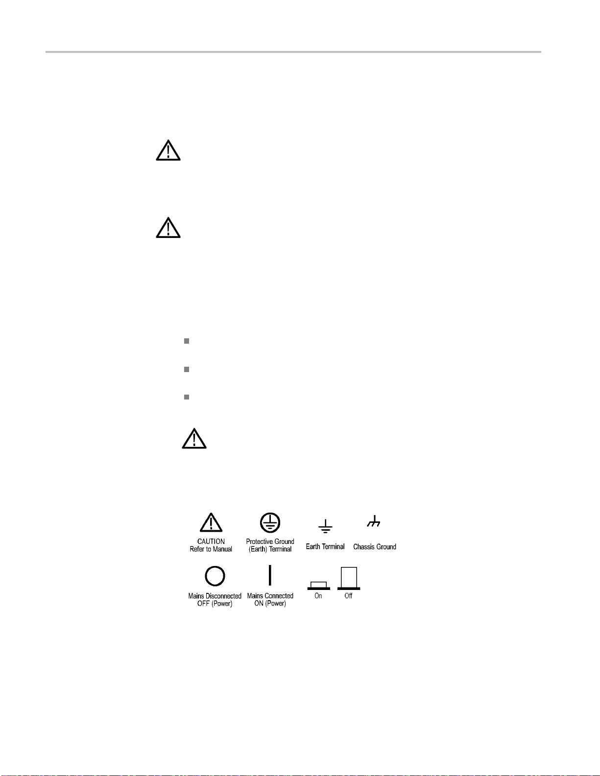
Symbols and terms on the product
These terms may appear on the product:
DANGER indicates an injury hazard immediately accessible
as you read the marking.
WARNING indicates an injury hazard not immediately
accessible as you read the marking.
CAUTION indicates a hazard to property including the product.
When this symbol is marked on the product, be sure to consu lt the manual to
find out the nature of the potential hazards and any actions which have to be
taken to avoid them. (This symbol may also be used to refer the user to ratings
in the manual.)
The following symbol(s) may appear on the product:

AFG1000 Series Specifications and Performance Verification
1
AFG1022
AFG1062
Preface
This manual provides instructions to verify the performance of the AFG1000
Series
Arbitrary Function Generator to the module level.
Unless noted otherwise, the term “AFG3000 Series” refers to the models in the
following table.
Table 1: Supported products
To prevent personal injury or damage to the arbitrary function generator, consider
the following before attempting service:
The procedures in this manual should be performed only by a qualified service
person.
Read the General Safety Summary and the Service Safety Summary at the
beginning of this document.
When using this manual for servicing, be sure to follow all warnings, cautions and
notes.
The manual consists of the following sections:
Specifications contains a description of the arbitrary function generator and
the characteristics that apply to it.
Performance tests contains procedures for confirming that the arbitrary
function generator functions properly and meets warranted limits.
The procedures described in this document should be performed every
12 months or after module replacement.
If the instruments do not meet performance criteria, repair is necessary.

Important safety information
2
AFG1000 Series Specifications and Performance Verification
Finding other information
This manual focuses on the performance verification of the arbitrary function
generator. See the following list for other documents supporting the instrument.
All documents except the Online Help are on the AFG1000 Series Arbitrary
Function
Generator Documentation CD-ROM that ship with instrument.
Document
AFG1000 Series Quick Start A quick reference to major features of the instrument and how they operate. It also provides
User Manual several tutorials to familiarize you with basic instrument features.
AFG1000 Series Programmer Manual An encyclopedia of topics that describe the arbitrary function generator interface and features,
AFG1000 Series Compliance and This document contains compliance and safety information.
Safety Instructions
AFG1000 Series Online Help A online help system, integrated with the User Interface application that ships with this
Manual conventions
Modules
Safety
Description
and gives background information on how to use them. It provides Menu Structures, User
Interface and Programming Information.
product. The help is preinstalled in the instrument.
This manual uses certain conventions that you should become familiar with.
Throughout this manual, any replaceable component, assembly, or part of the
arbitrary function generator is referred to generically as a module. In general, a
module is an assembly (such as a circuit board). Sometimes a single component is
a module; for example, the chassis of the arbitrary function generator is a module.
Symbols and terms related to safety appear in the Safety Summary near the
beginning of this manual.

AFG1000 Series Specifications and Performance Verification
3
Specifications
These specifications apply to the AFG1000 Series Arbitrary Function Generator.
All
specifications are guaranteed unless labeled "typical". Typical specifications
are
provided for your convenience but are not guaranteed.
Specifications that are check marked with the
indirectly) in the Performance tests section.
All specifications apply to the arbitrary function generator unless noted otherwise.
These specifications are valid under the following conditions:
The instrument must have been calibrated/adjusted at an ambient temperature
between +20 °C and +30 °C.
The instrument must be operating at an ambient temperature between 0 °C
and +40 °C.
The instrument must have had a warm-up period of at least 30 minutes.
The instrument must be in an environment with temperatu re, alti tude and
humidity within the operating limits described in these specifications.
Electrical specifications
Table 2: Operating mode
Characteristic Description
Run mode Continuous, Modulation, Sweep, and Burst
symbol are checked directly (or
Table 3: Waveforms
Characteristic Description
Standard
Numbers of channel 2
Arbitrary waveform
Waveform length
AFG1022 2 to 8,192
AFG1062 2 to 1M
Sampling rate
AFG1022 125 MS/s
AFG1062 300 MS/s
Exponential rise, Exponential fall, Sin(x)/x, Staircase, DC, etc. 45 built-in waveforms, User Defined
Resolution
Number of non-volatile 256
waveform memories
Memory si z e
Sine, Square, Ramp, Pulse, N oi se
14 bits
64 Mbyte for waveform storage
 Loading...