

Page 1

User Manual
AD951A/AD953A
MPEG Test System
Volume 1 of 2
071-1423-00
This document supports firmware versions:
AD95X MPEG Test Systems Version 6.7
AD960 Data Test Systems Version 3.0
www.tektronix.com
Page 2

Copyright ©Tektronix, Inc. All rights reserved. Licensed software products are owned by Tektronix or its
suppliers and are protected by United States copyright laws and international treaty provisions.
Use, duplication, or disclosure by the Government is subject to restrictions as set forth in subparagraph
(c)(1)(ii) of the Rights in Technical Data and Computer Software clause at DFARS 252.227-7013, or
subparagraphs (c)(1) and (2) of the Commercial Computer Software -- Restricted Rights clause at FAR
52.227-19, as applicable.
Tektronix products are covered by U.S. and foreign patents, issued and pending. Information in this
publication supersedes that in all previously published material. Specifications and price change privileges
reserved.
Tektronix, Inc., P.O. Box 500, Beaverton, OR 97077
TEKTRONIX and TEK are registered trademarks of Tektronix, Inc.
Trademarks and Patents
Windows™ is acknowledged as a trademark of Microsoft£ Corporation.
Pentium™ is acknowledged as a trademark of Intel Corporation.
HOTLink™ is acknowledged as a trademark of Cypress Semiconductor Corporation.
Dolby™ and the Double-D symbol are trademarks of Dolby Laboratories.
All trademarks acknowledged.
Licensed AAC Patents
08/937,950 5848391 5,291,557 5,451,954 5 400 433
5,222,189 5,357,594 5 752 225 5,394,473 5,583,962
5,274,740 5,633,981 5 297 236 4,914,701 5,235,671
07/640,550 5,579,430 08/678,666 98/03037 97/02875
97/02874 98/03036 5,227,788 5,285,498 5,481,614
5,592,584 5,781,888 08/039,478 08/211,547 5,703,999
08/557,046 08/894,844 5,299,238 5,299,239 5,299,240
5,197,087 5,490,170 5,264,846 5,268,685 5,375,189
5,581,654 05-183,988 5,548,574 08/506,729 08/576,495
5,717,821 08/392,756
It is a condition of these licensed products that they may not be copied, except to make single copies for
archival purposes, and may not be decompiled or reverse engineered.
Page 3

Software Warranty
Tektronix warrants that the media on which this software product is furnished and the encoding of the
programs on the media will be free from defects in materials and workmanship for a period of three (3)
months from the date of shipment. If a medium or encoding proves defective during the warranty period,
Tektronix will provide a replacement in exchange for the defective medium. Except as to the media on
which this software product is furnished, this software product is provided “as is” without warranty of any
kind, either express or implied. Tektronix does not warrant that the functions contained in this software
product will meet Customer’s requirements or that the operation of the programs will be uninterrupted or
error-free.
In order to obtain service under this warranty, Customer must notify Tektronix of the defect before the
expiration of the warranty period. If Tektronix is unable to provide a replacement that is free from defects in
materials and workmanship within a reasonable time thereafter, Customer may terminate the license for this
software product and return this software product and any associated materials for credit or refund.
THIS WARRANTY IS GIVEN BY TEKTRONIX IN LIEU OF ANY OTHER WARRANTIES,
EXPRESS OR IMPLIED. TEKTRONIX AND ITS VENDORS DISCLAIM ANY IMPLIED
WARRANTIES OF MERCHANTABILITY OR FITNESS FOR A PARTICULAR PURPOSE.
TEKTRONIX’ RESPONSIBILITY TO REPLACE DEFECTIVE MEDIA OR REFUND
CUSTOMER’S PAYMENT IS THE SOLE AND EXCLUSIVE REMEDY PROVIDED TO THE
CUSTOMER FOR BREACH OF THIS WARRANTY. TEKTRONIX AND ITS VENDORS WILL
NOT BE LIABLE FOR ANY INDIRECT, SPECIAL, INCIDENTAL, OR CONSEQUENTIAL
DAMAGES IRRESPECTIVE OF WHETHER TEKTRONIX OR THE VENDOR HAS ADVANCE
NOTICE OF THE POSSIBILITY OF SUCH DAMAGES.
Page 4

Page 5

Table of Contents
Volume 1
Volume 2
Preface iii. . . . . . . . . . . . . . . . . . . . . . . . . . . . . . . . . . . . . . . . . . . . . . . . . . .
Related Material iii. . . . . . . . . . . . . . . . . . . . . . . . . . . . . . . . . . . . . . . . . . . . . . . . .
Manual Conventions iii. . . . . . . . . . . . . . . . . . . . . . . . . . . . . . . . . . . . . . . . . . . . . .
Contacting Tektronix iv. . . . . . . . . . . . . . . . . . . . . . . . . . . . . . . . . . . . . . . . . . . . .
Introduction
Transport Stream Analyzer Sect. 1. . . . . . . . . . . . . . . . . . . . . . . . . . . . . . . . . . . . . . . . .
Packetized Elementary Stream Analyzer Sect. 2. . . . . . . . . . . . . . . . . . . . . . . . . . . . . .
T-STD Buffer Analyzer Sect. 3. . . . . . . . . . . . . . . . . . . . . . . . . . . . . . . . . . . . . . . . . . .
Tracer Sect. 4. . . . . . . . . . . . . . . . . . . . . . . . . . . . . . . . . . . . . . . . . . . . . . . . . . . . . . . . .
Player Sect. 5. . . . . . . . . . . . . . . . . . . . . . . . . . . . . . . . . . . . . . . . . . . . . . . . . . . . . . . . .
Monitor/Recorder Sect. 6. . . . . . . . . . . . . . . . . . . . . . . . . . . . . . . . . . . . . . . . . . . . . . . .
Transport Stream Editor Sect. 7. . . . . . . . . . . . . . . . . . . . . . . . . . . . . . . . . . . . . . . . . . .
Multiple Sect. 8. . . . . . . . . . . . . . . . . . . . . . . . . . . . . . . . . . . . . . . . . . . . . . . . . . . . . . .
Make Seamless Wizard Sect. 9. . . . . . . . . . . . . . . . . . . . . . . . . . . . . . . . . . . . . . . . . . .
Stream Monitor Plus Sect. 10. . . . . . . . . . . . . . . . . . . . . . . . . . . . . . . . . . . . . . . . . . . . . .
Elementary Stream Analyzer Sect. 11. . . . . . . . . . . . . . . . . . . . . . . . . . . . . . . . . . . . . . .
BS Digital Multiplexer Sect. 12. . . . . . . . . . . . . . . . . . . . . . . . . . . . . . . . . . . . . . . . . . . .
BC Digital Multiplexer Sect. 13. . . . . . . . . . . . . . . . . . . . . . . . . . . . . . . . . . . . . . . . . . . .
Carousel Analyzer Sect. 14. . . . . . . . . . . . . . . . . . . . . . . . . . . . . . . . . . . . . . . . . . . . . . .
Carousel Generator Sect. 15. . . . . . . . . . . . . . . . . . . . . . . . . . . . . . . . . . . . . . . . . . . . . . .
Transport Stream Maker Sect. 16. . . . . . . . . . . . . . . . . . . . . . . . . . . . . . . . . . . . . . . . . . .
Transport Stream Cutter Sect. 17. . . . . . . . . . . . . . . . . . . . . . . . . . . . . . . . . . . . . . . . . . .
ScriptP Sect. 18. . . . . . . . . . . . . . . . . . . . . . . . . . . . . . . . . . . . . . . . . . . . . . . . . . . . . . . . .
Custom SI Scripting Sect. 19. . . . . . . . . . . . . . . . . . . . . . . . . . . . . . . . . . . . . . . . . . . . . .
AD951A/AD953A MPEG Test System User Manual
i
Page 6

Table of Contents
ii
AD951A/AD953A MPEG Test System User Manual
Page 7

Preface
This manual describes the software applications available to the Tektronix
AD951A/AD953A MPEG Test System. All applications are installed; access will be
dictated by the security dongle and those options purchased.
The manual is divided into sections, each describing one application. An overview of the
applications is provided in the Introduction section.
Related Material
Getting Started Manual (071-1422-xx)
Describes the installation of the MPEG Test System.
Additional documentation, such as ReadMe files, may be included on the installation disks.
The following URLs access the Web sites for the standards organizations listed (the URLs
listed were valid at the time of writing):
x MPEG-2 standards (International Organization for Standards) - http://www.iso.ch/
x DVB standards (European Technical Standards Institute) - http://www.etsi.org/
x ATSC standards (Advanced Television Systems Committee) - http://www.atsc.org/
Manual Conventions
Naming conventions for the interface elements are based on standard Windows naming
conventions. Naming conventions for MPEG-2, ATSC, and DVB structures follow the
conventions derived from the standards documents listed above. In addition, the following
formatting conventions apply to this manual:
Bold text refers to specific interface elements that you are instructed to select, click, or
x
clear.
Example: Select
x Boxed text represents buttons on the user interface.
Example: Select Trigger on the Setup dialog.
x Mono-spaced text can indicate the following:
x Text you enter from a keyboard
Example: Enter the network identity (http://TSMonitor01)
x Characters you press on your keyboard
Example: Press
x Paths to components on your hard drive
Example: The program files are installed at the following location: C:\Program
Files\Tektronix\
Settings from the Configuration menu.
CTRL+C to copy the selected text.
AD951A/AD953A MPEG Test System User Manual iii
Page 8

Preface
Contacting Tektronix
Phone 1-800-833-9200*
Address Tektronix, Inc.
Department or name (if known)
14200 SW Karl Braun Drive
P.O. Box 500
Beaverton, OR 97077
USA
Web site www.tektronix.com
Support - N & S America
Sales support 1-800-833-9200, select option 1*
Service support 1-800-833-9200, select option 2*
Technical support Email: techsupport@tektronix.com
1-800-833-9200, select option 3*
* - toll free in North America.
6:00 a.m. -- 5:00 p.m. Pacific time
After office hours, please leave a voice mail
message.
Support - Europe & the Rest of the World
Sales Support +44 (0)1344 392000
Service & Technical Support
Telephone +44 (0)1223 200700
Fax +44 (0)1223 200701
iv AD951A/AD953A MPEG Test System User Manual
Page 9

Introduction
Introduction............................................................. 3
The Software Suite.................................................. 3
Proprietary Analysis Software ................................ 6
MPEG Files............................................................. 7
Format............................................................... 7
Locations .......................................................... 7
AD951A/AD953A MPEG Test System User Manual 1
Page 10

Introduction
2 AD951A/AD953A MPEG Test System User Manual
Page 11
Introduction
All applications in the MPEG Test System family operate under a Windows operating
system (refer to the Specifications section in the AD951A/AD953A Technical Reference
Manual, 071-1425-xx).
The Software Suite
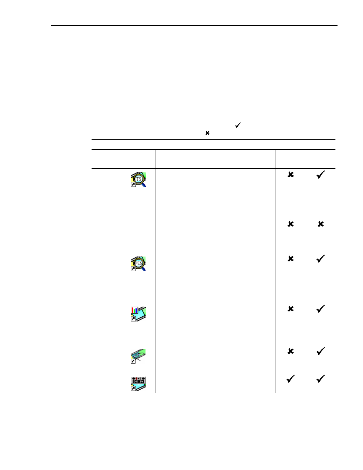
Table 1 lists the applications available to the MPEG Test System. The table shows which
applications are included in the standard installation (
that can be enabled as an upgrade option (
Table 1: AD951A/AD953A Software Applications
Section
Number
1 Transport Stream (TS) Analyzer
Desktop
Icon
Introduction
); also shown are those applications
).
Application \ Product AD951A AD953A
Transport stream analysis with user-selectable
MPEG-2, DVB and ATSC conformance tests.
Shows transport structure, header contents,
hexadecimal packet contents, PCR timing
/transport rate graphs and an error message log.
TS Analyzer Lite
As for the TS Analyzer except that the file size of
transport streams to be analyzed is limited to
192 MB.
2 Packetized Elementary Stream (PES)
Analyzer
PES analysis with selectable test options. Shows
PES program structure, header contents, packet
contents, PTS/DTS timing graphs and analysis
reports.
3 Transport Stream – System Target
Decoder (T-STD) Buffer Analyzer
Analyzes program streams modeling their
behaviour in, and their conformance to, the
MPEG-2 T-STD Buffer Model.
4 Tracer
Views the message log produced by T-STD
Buffer Analyzer.
5
Player
Records and Plays out MPEG-2 streams.
AD951A/AD953A MPEG Test System User Manual 3
Page 12

Introduction
Table 1: AD951A/AD953A Software Applications
Section
Number
Desktop
Icon
Application \ Product AD951A AD953A
6
7
8
9
TS Monitor/Recorder
Monitors and/or Records MPEG-2 transport
streams – gives viewing of the transport stream
multiplex, triggered and filtered recordings,
logging of events and generation of an external
alarm signal linked to transport stream events.
TS Editor
Viewing and Editing of transport stream packets,
via a hexadecimal view of the packet contents
and semantic interpretation of the header.
Provides facilities to: remap PIDs, recalculate
PCR values and introduce PCR inaccuracies.
Multiplexer
Multiplexes table information and packetised
elementary streams together to synthesise new
transport streams. A fine level of control is
provided to allow non-conformances and test
cases to be specified for new transport streams.
Make Seamless Wizard
Guides the user through the process of creating
an MPEG-2 file for use by Stream Player in
continuously looped operation.
10
11
12
Stream Monitor Plus
Monitors one or more transport streams.
Updates graphs, status displays and event logs in
real time.
Can make sequences of recordings, unattended,
whenever user specified events occur.
Elementary Stream Analyzer
Elementary Stream analysis at video picture and
audio level. This includes vector graphs and
macroblock picture quality.
Broadcast Satellite Digital
Multiplexer
The BSDM allows multiple transport streams,
together with TMCC information, to be
multiplexed into a BS Digital stream. A single
transport stream may also be exported from an
existing BS Digital stream.
4 AD951A/AD953A MPEG Test System User Manual
Page 13
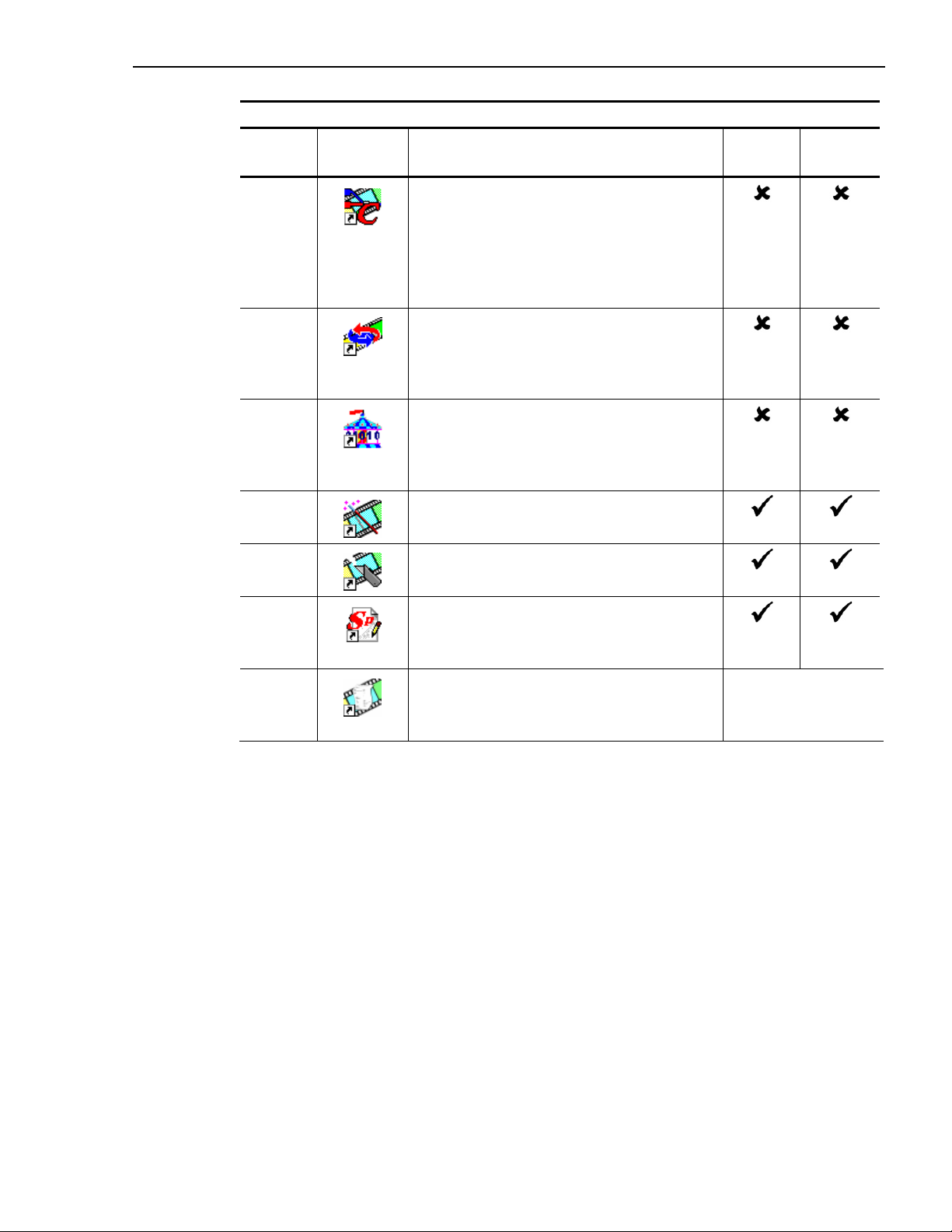
Table 1: AD951A/AD953A Software Applications
Section
Number
Desktop
Icon
Application \ Product AD951A AD953A
Introduction
13
Broadcast Cable Digital Multiplexer
The BCDM allows multiple transport streams,
together with TSMF information, to be
multiplexed to produce ISDB-C streams (TSMF
streams). It can also demultiplex existing TSMF
streams and allow the TSMF to be edited.
14 Carousel Analyzer
Data analysis showing structure, bitrate,
repetition rate, syntax and semantics of data
items.
15
16
17
Carousel Generator
Provides in-depth off-line generation of MPEG-2,
DVB transport streams containing a range of
data broadcast protocols.
TS Maker
Creates and initialises files for recording.
TS Cutter
Extracts sections of MPEG-2 files to new files.
18 Script Pad
Enables users to create and modify System
Information (SI) scripts.
19 Custom SI Scripting
A background document which describes the
scripting arrangements of the AD951A/AD953A.
Documentation only
Standalone Operation
All applications (with the exception of Player, Monitor/Recorder and Stream Monitor Plus)
are available as standalone options that can be installed and used on a PC (For more
information about the PC specification required, refer to the AD951A/AD953A Technical
Reference Manual, 071-1425-xx).
Upgrading
Upgrades are available for the following products:
x AD95x MPEG Test System
x AD951A/AD953A MPEG Test System
x Standalone MPEG Test System.
All applications are available for upgrading, with the exception of Player, Monitor/Recorder
and Stream Monitor Plus in standalone systems.
AD951A/AD953A MPEG Test System User Manual 5
Page 14

Introduction
Proprietary Analysis Software
Analysis of proprietary DTV standards is carried out in the MPEG Test System by
the addition of plug-in modules. Where these are supplied, any documentation
provided will be included in Adobe PDF format as part of the installation procedure.
For information on the range and availability of proprietary analysis software, please
contact Tektronix directly or an approved representative.
6 AD951A/AD953A MPEG Test System User Manual
Page 15

MPEG Files
Format
All files created by MPEG Test System applications start on a packet boundary. That is the
first byte of a file contains the first byte of the first packet in that file.
Files which are produced or modified by other equipment or software must conform to this
convention if they are to be opened by MPEG Test System applications. No harm will occur
to a MPEG Test System if a file with an invalid format is opened.
Locations
MPEG Test System hardware uses two types of disk drives. The operating system, MPEG
Test System applications and general data are stored on a standard computer hard disk
drive. This is usually configured as Drive C:
Recording and playout of ATSC, DVB and MPEG-2 streams requires much higher data
transfer rates and consistency of performance. To achieve this, a high performance disk
drive is incorporated.
Introduction
Other than the greater performance there is no difference in the function of the two types of
disk drives. Files may be copied to and from the high performance drives in the same way
as for the standard drives.
Additional high performance drives may be connected to a MPEG Test System. These will
be mapped to other drive letters if Drive E: is already taken. If the MPEG Test System was
supplied with extra disks configured, these will be documented in the Delivery Note.
AD951A/AD953A MPEG Test System User Manual 7
Page 16

Introduction
8 AD951A/AD953A MPEG Test System User Manual
Page 17

Section 1
Transport Stream Analyzer
This section describes the Transport Stream Analyzer software.
If you have purchased the AD-TSAL software option, the functionality is exactly the same, except that the
file size of transport streams to be analysed is limited to 192 MB.
Description of Features ...........................................3
Starting the Program................................................5
Initial Appearance.............................................6
Initial Menu Options.........................................6
Packet Size Selection...............................................9
Stream Test Settings..............................................10
MPEG2 Test Options......................................12
DVB Test Options ..........................................13
ATSC Test Options ........................................16
Scripts and Modules ..............................................17
Handling Scripts and Modules .......................18
Script and Module Selection...........................19
Expert Mode ...................................................20
Opening a file ........................................................22
SI Filtering......................................................25
Storing SI information ....................................28
Menus and Controls ..............................................29
Menus and Options.........................................29
Toolbars ..........................................................34
Status Bar........................................................36
Slider Bar........................................................37
Find Transport Packet ...........................................39
Search by Criteria ...........................................40
Goto Packet.....................................................41
Transport Navigator ..............................................42
Transport Structure Diagram..........................43
Selecting a PID ...............................................44
Looking at the SI/PSI/PSIP Tables.................46
Table Structure ......................................................47
Looking at the Packets ................................... 47
Looking at the Complete Table (Hex View).. 53
Transport Packet Hex View.................................. 54
Packet Size ..................................................... 55
Packet Header ................................................ 55
Adaptation Fields ........................................... 56
Transport Private Data ................................... 56
Transport Packet Header ...................................... 57
Adaptation Fields ........................................... 58
Message Log......................................................... 59
Packet Selection ............................................. 60
Multiplex Statistics............................................... 62
Histogram View ............................................. 62
Pie Chart View............................................... 67
Graphing Features................................................. 68
PCR Statistics Graphs........................................... 72
PCR Interval................................................... 72
Arrival Time Jitter (Arrival) .......................... 73
Inaccuracy (PCR-AC) .................................... 74
Overall Jitter (PCR-OJ).................................. 75
Frequency Offset (PCR-FO) .......................... 76
PCR Drift Rate Measurement (PCR_DR) ..... 76
Bit Rate Graphs .................................................... 77
Instantaneous Transport Rate (ITR)............... 77
PID Bitrate ..................................................... 80
Electronic Program Guide .................................... 81
Schedule Window .......................................... 83
References ............................................................ 85
AD951A/AD953A MPEG Test System User Manual 1
Page 18

1 - Transport Stream Analyzer
2 AD951A/AD953A MPEG Test System User Manual
Page 19

Transport Stream Analyzer - 1
Description of Features
The Transport Stream Analyzer allows the contents of a previously recorded or synthesised
transport stream to be interpreted and viewed in a variety of formats. It also performs a
series of user selectable MPEG-2, DVB and ATSC conformance tests. Errors found in
specific packets are cross-referenced to enable each packet to be selected from the reference
in the conformance report.
Information can be viewed in graphical and textual formats. To analyze and view the
Packetised Elementary Stream (PES) packets use the companion program PES Analyzer,
which can be run at the same time as this TS Analyzer. More than one instance of the
program can be run simultaneously. This allows comparison of different files.
The functionality provided includes:
x Histogram or pie chart display of multiplex structure showing the Packet Identifier (PID)
of all packets that are present in the stored file.
x Diagrammatic display and interpretation of Transport Stream packet header and
adaptation field information for individual packets.
x Hexadecimal representation of Transport Stream packet, with color coding to
differentiate the header, adaptation field and payload information.
x Location of a Transport Stream packet to match a particular condition in the packet
header.
AD951A/AD953A MPEG Test System User Manual 3
Page 20

1 - Transport Stream Analyzer
x Electronic Program Guide for DVB and ATSC streams.
x Display and interpretation of MPEG-2 Program Specific Information (PSI) tables:
x Program Association Table (PAT)
x Conditional Access Table (CAT)
x Program Map Table (PMT)
x Transport Stream Description Table (TSDT)
x Network Information Table (NIT)
x Display and interpretation of DVB Service Information (SI) tables:
x Network Information Table (NIT) as defined by DVB
x Bouquet Association Table (BAT)
x Service Description Table (SDT)
x Event Information Table (EIT)
x Running Status Table (RST)
x Time and Date Table (TDT)
x Stuffing Table (ST)
x Time Offset Table (TOT)
x Discontinuity Information Table (DIT)
x Selection Information Table (SIT)
x Single Frequency Network (SFN) information
x Display and interpretation of ATSC Program and System Information Protocol (PSIP)
tables:
x Master Guide Table (MGT)
x System Time Table (STT)
x Terrestrial Virtual Channel Table (TVCT)
x Cable Virtual Channel Table (CVCT
x Regional Ratings Table (RRT)
x Event Information Table (EIT)
x Extended Text table (ETT)
x Display and interpretation of ATSC A/57 table (Ref [2]:ATSC Standard A/57)
x Program Information Table (PIT)
x Display and interpretation of ARIB tables
x
Network Information Table (NIT)
x Service Description Table (SDT)
x Event Information Table (EIT)
x Stuffing Table (ST)
x Time Offset Table (TOT)
x Discontinuity Information Table (DIT)
x Selection Information Table (SIT)
x Broadcaster Information Table (BIT)
x Linked Description Table (LDT)
x Network Board Information Table (NBIT)
4 AD951A/AD953A MPEG Test System User Manual
Page 21
Transport Stream Analyzer - 1
x Software Download Trigger Table (SDTT)
x Common Data Table (CDT)
x ISDB-T Information Packet (IIP)
x Statistical display of the components of the Transport Stream and their data rates on a
PID by PID basis.
x Calculation and graphical display of the instantaneous bit rate for each PID and for the
entire Transport Stream from Program Clock Reference (PCR) time stamp values.
x Calculation and graphical display of PCR information:
x The arrival interval between successive PCRs on a PID by PID basis.
x The PCR accuracy for each PCR on a PID by PID basis.
x The network, or arrival time, jitter on a PID by PID basis.
x The overall jitter on a PID by PID basis.
x The PCR frequency offset on a PID by PID basis.
x The PCR drift rate on a PID by PID basis.
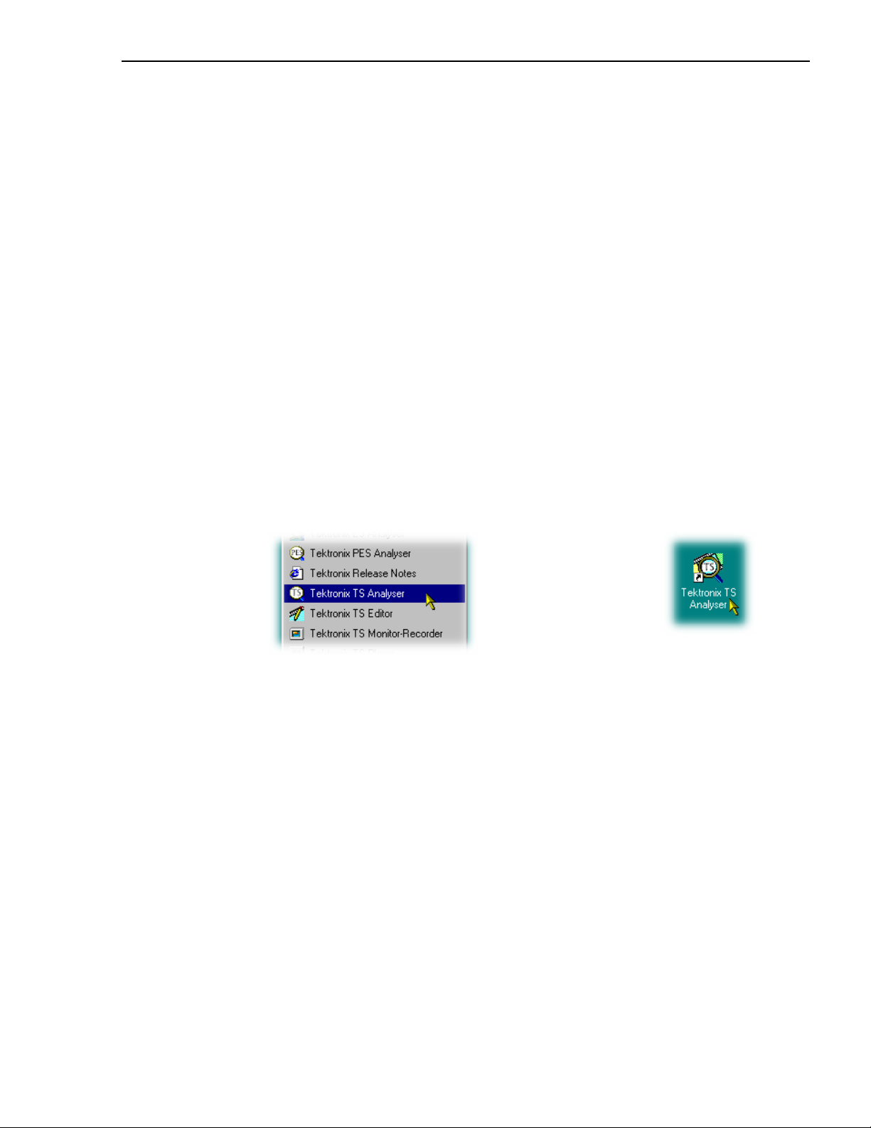
Starting the Program
The program may be started by selecting
the
Tektronix TS Analyser option from the
Start -> Programs menu.
or
by double clicking on the
Tektronix TS Analyser
Shortcut on the desktop.
AD951A/AD953A MPEG Test System User Manual 5
Page 22
1 - Transport Stream Analyzer
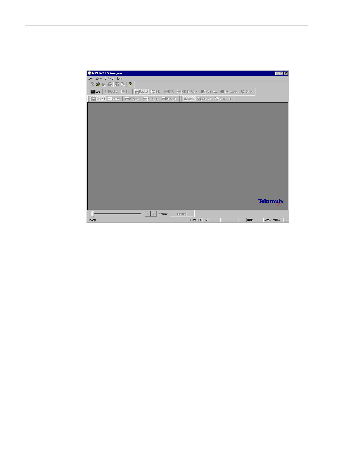
Initial Appearance
Once the program has started and is ready for use it will open a Main Window. When the
program starts the main window looks like this:
The Toolbars (rows of buttons above the dark grey area of the empty window) provide
quick access to the main menu functions. The toolbars can be docked on any edge of the
window or floated (see page 29 et seq).
The Status line at the bottom of the window displays status information and tooltips and,
because no file is open, that 0% of a stream file has been analysed.
Above the Status line is the Slider bar, for selecting packets within the file. This may be
moved to the top of the window or floated.
Initial Menu Options
Users are presented with different menus and options, depending on whether or not a file is
open for analysis. The menu options available when the program has just been started, or
after a file is closed, are given below. Greyed out options are not available at this time.
(A check mark
9 means that it is hidden.)
9 next to an option shows that the window or toolbar is currently visible; no
6 AD951A/AD953A MPEG Test System User Manual
Page 23
Transport Stream Analyzer - 1
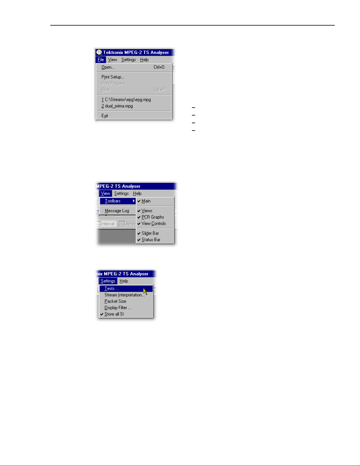
File Menu Options
Open ... Opens a stream file for analysis. The
program opens the file selection
dialogue allowing the user to choose
the required file.
Print Setup ... Opens a dialogue for selecting which
printer and associated options to use.
1 <filename> A list of the four most recently
2 <filename> analysed files. If the program has
3 <filename> recently been installed the list may
4 <filename> be empty or hold less than four files.
Selecting a filename opens that file
for analysis.
Exit Finishes running the program.
View Menu Options
Toolbar Ź Shows or hides the sub-menu which
allows the toolbars to be hidden or
shown.
Settings Menu options
Message Log Toggles the Message Log window
between being displayed or not.
Tests… Displays a dialog for selecting the
tests to be used in stream analysis.
Stream Interpretation… Displays a dialog for
selecting scripts and modules to be
used in stream analysis.
Packet Size Allows the packet size of the
incoming stream to be designated.
Display Filter… Allows designated table Ids to be
filtered from the Transport Navigator
display.
Store all SI When enabled, stores all SI
information during analysis. When
disabled, data for tables that are
filtered out is not stored.
AD951A/AD953A MPEG Test System User Manual 7
Page 24

1 - Transport Stream Analyzer
Help Menu Options
About StreamAnalyser… Displays Program
Number, Version and copyright
information.
8 AD951A/AD953A MPEG Test System User Manual
Page 25

Transport Stream Analyzer - 1
Packet Size Selection
Specifies which packet size will be used to interpret the stream. (N.B. selecting the wrong
packet size will cause analysis to report large numbers of errors, and the Transport
Navigator and other views to show nonsense.) The options are:
Select
Packet Size from the Settings menu to open the
Transport Packet Size dialog.
Note that the Packet Size dialog is available when a file is
open, but all activity is disabled.
The following dialog is displayed:
Auto detect packet
size
Automatically detect the packet size used in a file when it is
opened. If the program fails to determine the correct packet size
it can be selected using the other Packet Size options.
188 byte packets
204 byte packets
Analyze files as a stream of 188 byte packets.
Analyze files as a stream of 204 byte packets.
If large numbers of errors are reported during analysis, try selecting a different packet size.
AD951A/AD953A MPEG Test System User Manual 9
Page 26
1 - Transport Stream Analyzer
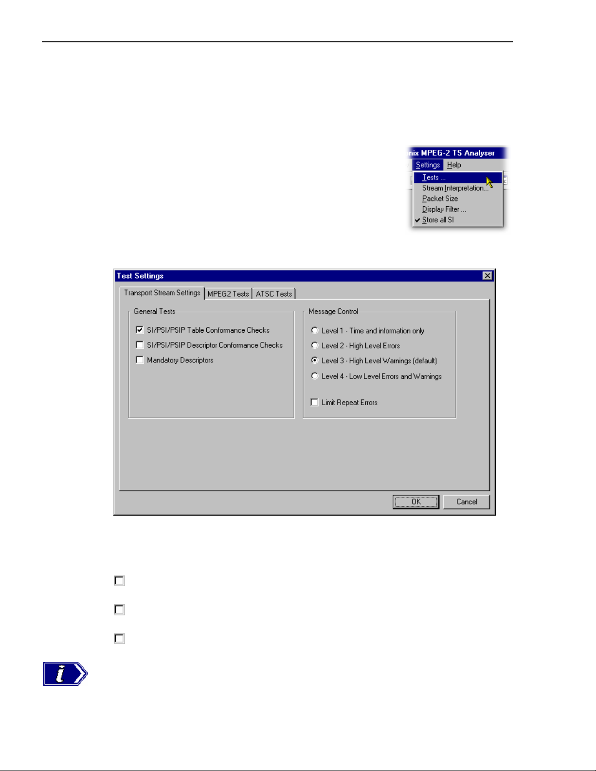
Stream Test Settings
The stream Test Settings can only be modified before opening a file. To change these
settings and options once a file has been opened: the file must be closed, the settings
modified and the file re-opened.
Select
Tests... from the Settings menu to open the Test
Settings dialog.
Note that the
Tests… option is not available when a file is
open.
The Test Settings dialogue contains a number of tabbed pages as described below:
Tabs are shown only for the test sets available, as set in the Stream Interpretation screen.
General Tests
SI/PSI/PSIP Tables
Conformance Checks
IS/PSI/SI Descriptor
Conformance Checks
Mandatory Descriptors
The ATSC standard, in particular, specifies differences in the allowed and mandatory
descriptors based upon whether the context is cable, satellite or terrestrial. The analyzer does
not know the intended context, so may log warnings that do not apply in all contexts. In
these situations the log will indicate the contexts that are relevant.
10 AD951A/AD953A MPEG Test System User Manual
Enables conformance check of the SI/PSI tables.
Enables conformance checks of the SI/PSI descriptors.
Checks for inclusion of mandatory descriptors within each
SI/PSI table.
Page 27

Transport Stream Analyzer - 1
Message Control
Message Control is used to limit the level of error reporting during analysis. Select the error
level required.
Limit Repeat Errors
Multiple reports (greater than 20) of errors can be limited, by enabling the Limit Repeat
Errors
checkbox.
When this option is enabled, up to 20 reports are made for a single error type, but thereafter
a the total in excess of twenty is displayed at the end of the analysis.
AD951A/AD953A MPEG Test System User Manual 11
Page 28
1 - Transport Stream Analyzer
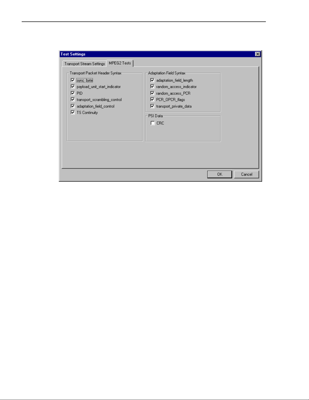
MPEG2 Test Options
These test options are laid out in a similar hierarchy to the conformance specifications in
the MPEG-2 standard. For a full description of each test, see section 2.3.2.1 of the MPEG-2
standard ISO/IEC 13818-4 (Ref [9]). The dialog uses the same names as those used in the
standard.
Enable an option in the dialog to check for conformance to that part of the specification. A
test is enabled when there is a check mark in the box. Conformance is not tested when the
box is not checked.
12 AD951A/AD953A MPEG Test System User Manual
Page 29

Transport Stream Analyzer - 1
DVB Test Options
These test options are laid out according to the Priority scheme used in the conformance
specifications for the DVB standards. Refer to section 5.2 of the DVB standard TR 101 290
(Ref [1]) for a full description. The dialog uses the same names as those in the standard.
Enable an option to check for conformance to the related part of the specification. An
option is enabled when there is a check mark in the box. Conformance is not tested when
the box is not checked.
DVB 2.2 CRC-error and MPEG CRC tests refer to the same test and are linked in these
dialogs. Enabling/Disabling either test in one of the dialogs will also enable/disable the test
in the other dialog.
DVB tests also apply to both ISDB-S and ISDB-T standards.
AD951A/AD953A MPEG Test System User Manual 13
Page 30
1 - Transport Stream Analyzer
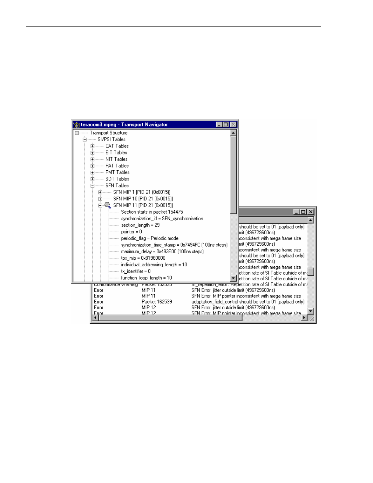
Single Frequency Network (SFN) Errors
SFN error analysis is only applicable in DVB interpretation mode. The option is enabled
when there is a check mark in the box. Conformance is not tested when the box is not
checked.
All of the tests specified in DVB standard TR 101 290 (Ref [1]) are carried out.
Although MIPs are not SI tables, they are listed in the Transport Navigator window as such
for convenience. SFN errors are presented in the Message Log.
14 AD951A/AD953A MPEG Test System User Manual
Page 31

Transport Stream Analyzer - 1
Advanced DVB Test Settings
The advanced DVB test settings dialog provides defaults for (and an opportunity to change)
a selection of Priority 3 DVB test settings.
The dialog is accessed using the
DVB Tests tab.
Advanced Test Settings… button on the Test Setting -
AD951A/AD953A MPEG Test System User Manual 15
Page 32
1 - Transport Stream Analyzer
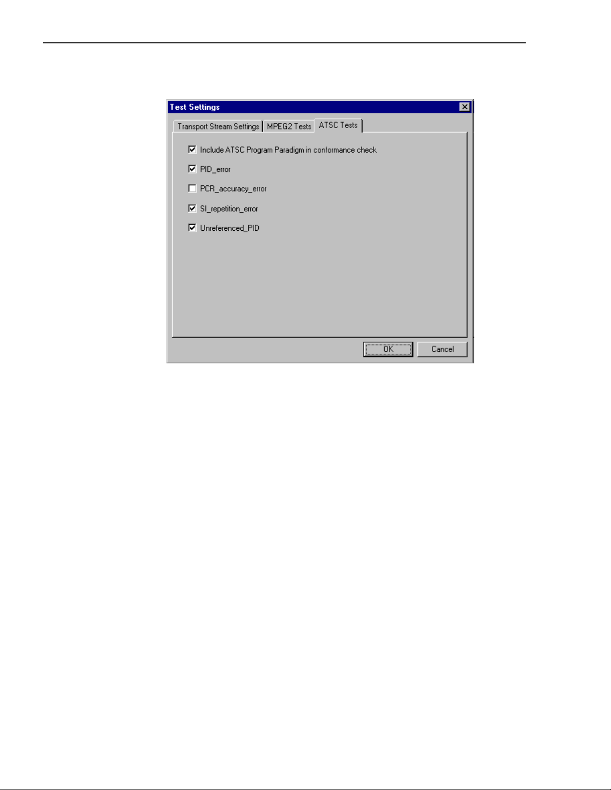
ATSC Test Options
These test options are laid out according to the Priority scheme used in the conformance
specifications for the ATSC standards. Refer to A/65 Program and System Information
Protocol for Terrestrial Broadcast and Cable (Ref [3]) for a full description. The dialog
uses the same names as those in the standard
Enable an option to check for conformance to the related part of the specification. An
option is enabled when there is a check mark in the box. Conformance is not tested when
the box is not checked.
PID_error, PCR_accuracy_error, SI_repetition_rate and unreferenced_PID conform to
the equivalent DVB tests.
Include ATSC Program Paradigm in conformance check is
specific to ATSC streams.
16 AD951A/AD953A MPEG Test System User Manual
Page 33

Transport Stream Analyzer - 1
Scripts and Modules
SI scripts and modules are available to the Transport Stream Analyzer to enable SI table and
descriptor data to be analysed successfully. Whilst scripts are mainly used to enable
analysis of SI data dictated by the various international standards, modules tend to be used
to enable analysis of proprietary SI.
Essential scripts and modules are installed and enabled using the Stream Interpretation
dialog. In the absence of any enabled scripts or modules, only the PAT table will be
analysed, all other data will be presented as private data.
A listing of the currently available scripts is given in the Custom SI Scripting section of this
manual. In addition, scripts may be customised to provided analysis of private data.
Modules and their documentation are supplied when required. As a security measure, the
use of some modules may require dongle permissions to be set.
If a suitably configured script is selected and enabled before a stream is analysed, custom
data will be analysed when the stream is opened. If the script is not selected or enabled the
stream will not fail to be analysed, but any custom data will be reported as either an error in
the stream configuration or as private or unknown data.
Scripts and modules can only be selected and enabled when no files are open. The Stream
Interpretation dialog is available when a file is open, but all activity is disabled.
Note that a script file will not be used for analysis until:
x It is present in the Scripts text-box in the current analysis mode.
x It is successfully enabled by closing the Stream Interpretation dialog using the OK
button.
AD951A/AD953A MPEG Test System User Manual 17
Page 34

1 - Transport Stream Analyzer
p
Handling Scripts and Modules
To open the Stream Interpretation dialog, with all files
closed select the
Settings menu.
The Stream Interpretation dialog is displayed as shown
below:
Script and
Module
Selection
Stream Interpretation… option from the
Current
Scri
ts
Expert Mode controls
Current
Modules
The top half of the dialog is concerned with selecting scripts and modules. The two text
boxes (Scripts and Modules) show the scripts and modules currently selected. The area
between the two text boxes is dedicated to Expert mode controls.
18 AD951A/AD953A MPEG Test System User Manual
Page 35

Transport Stream Analyzer - 1
Script and Module Selection
The selection area of the Stream Interpretation dialog is best viewed and used from left to
right.
Base Standard section allows the MPEG, DVB, ATSC or ISDB standard to be
The
selected for analysis.
MPEG-2 only
Interprets and analyses the packets in conformance to the MPEG-2
standards.
DVB
Interprets and analyses the Transport Stream Packets according to the
specifications of the DVB and MPEG-2 standards.
ATSC
Interprets and analyses the Transport Stream Packets according to the
specifications of the ATSC and MPEG-2 standards.
ISDB
Interprets and analyses the Transport Stream Packets according to the
ARIB and MPEG-2 standards
The standard selected will dictate the availability of the remaining options in the Extensions
and Data Standard sections.
The
Extensions section allows country-specific extensions to be added to the basic
standard scripts. If
None is selected, only the standard scripts are listed in the Scripts text-
box. The remaining country-specific extensions add extra scripts to the current listing. As
with the Base Standard, the choice of
options in the
Data Standards section. The Custom selection allows users to include their
Extensions option will dictate the availability of the
own selection of scripts using Expert Mode.
The
Data Standards section offers a choice of data-specific scripts.
The last section,
Proprietary Standards, lists the proprietary modules currently available.
Note that the scripts and modules listed by default are those resident in the default
installation directory (i.e. tektronix\testsystem\modules). Other directory locations can be
specified in Expert Mode. All selections will be retained between TS Analyzer sessions.
Syntax Checking
Scripts are syntactically analysed when the OK button is selected. They are also checked
when the application is opened. A fault in the syntax of a script will not necessarily prevent
a stream from being analysed, but it may result in incomplete analysis of the stream.
Scripts listed in the Scripts text-box will not be used for stream analysis until they have
been successfully checked; that is, the application has been opened or the Stream
Interpretation dialogue has been closed with no script-related error messages issued.
An intermediate check of scripts listed in the Scripts text-box can be made by selecting the
Reload Scripts button. This performs the same action as the OK button but leaves the
dialog open. Similarly, the Reload Modules button performs an intermediate check on the
listed modules.
Syntactic errors will be indicated and reported in the Message Log.
AD951A/AD953A MPEG Test System User Manual 19
Page 36

1 - Transport Stream Analyzer
Expert Mode
Expert Mode allows the user to select and customise the scripts and modules to be
used in stream analysis. Note that when the expert mode is selected, the Custom extension
option is automatically selected and that the management buttons are enabled. In Expert
mode, all scripts become available to be added to the script list. The scripts will be checked
and loaded, ready to be used for analysis, when the OK button is selected.
Script Management Buttons
The script management buttons act on the scripts currently listed in the Scripts text-box.
Script files are parsed in the order that they are listed; in some circumstances this
may be important. To move a file in a list, highlight the file name and select the Up
or Down arrow button as required. Each press of the button will move the file up
or down one place in the list until it reaches the top or the bottom.
Add a script to the list: A standard Windows file selection dialog is opened. The
default file extension is
added to the bottom of the list. If necessary, it can be moved using the Up and
Down buttons.
Scripts can be loaded from any directory.
Delete the highlighted script.
Change scripts' default directory: By default, all scripts are found in a default
directory created during installation (i.e. tektronix\scripts). This button may be
used to set a different default directory.
Note that all scripts supplied by Tektronix in the default installation are installed in
a single directory; as long as this directory is designated as the default directory,
they will work satisfactorily.
Script
management
.scp. Select the required file. The selected script will be
Module
management
20 AD951A/AD953A MPEG Test System User Manual
Page 37

Transport Stream Analyzer - 1
View highlighted script with the associated application; by default, script files are
associated with the ScriptPad utility.
For a script file to be viewed successfully, the file extension (.scp) must be
associated with a text editor in the MS Windows environment. The MPEG Test
System installation program associates by default a script editing utility called
ScriptPad; the user may use another text editor, e.g. MS Notepad, if preferred.
ScriptPad is a simple script editor that can be installed with the MPEG Test
System. Scripts can be viewed and edited as required (depending upon the file
permissions).
Module Management Buttons
The module management buttons act on the modules currently listed in the Modules textbox.
Add a module to the list: A standard Windows file selection dialog is opened. The
default file extension is
added to the list; list order is not important as it is with scripts.
Note that some specialised modules need to be security enabled via the dongle. In
these cases, a warning will be issued when the module is reloaded.
.dll. Select the required file. The selected module will be
Delete the highlighted module.
Change modules' default directory: By default, all modules are found in a default
directory created during installation (i.e. tektronix\testsystem\modules). This
button may be used to set a different default directory.
Note that all modules supplied by Tektronix in the default installation are installed
in a single directory; as long as this directory is designated as the default directory,
they will work satisfactorily.
AD951A/AD953A MPEG Test System User Manual 21
Page 38

1 - Transport Stream Analyzer
Opening a file
Any file holding a recorded or synthesised sample of a stream can be opened for analysis by
this program. To analyze the PES packets open the file in the PES Analyzer. A file can be
opened by both the TS and PES Analyzers at the same time.
Opening a file from the Menus and Toolbar
To open a file select the Open ... option from the
File menu. If the required file is in the list of
recently analysed files then it can be opened from
the list to save using the open file dialogue.
Alternatively use the
There is a shortcut button available on the Toolbar
for opening a file, which uses the standard file open
symbol:
Ctrl+O keyboard shortcut.
Opening a file from Windows Explorer or a File Browser Window
A new copy of the program can be run and a selected file opened in a single operation by
selecting a Stream File in Windows Explorer or a File Browser window
Place the pointer over the file name or icon, press the right mouse button to pop-up a menu
and then select the
When the program is started with a selected file the last set of program options will be used.
Analyse option
22 AD951A/AD953A MPEG Test System User Manual
Page 39

Transport Stream Analyzer - 1
Window Layout
Transport Navigator and Message Log windows are opened as soon as the file is opened.
The layout of the windows will have been saved from the last time the program was used. If
the program has just been installed the windows will be in the application default Cascade
arrangement which looks like this:
Many users re-arrange the windows so that the Transport Navigator and Message Log do
not overlap. The examples in this manual often use this arrangement:
AD951A/AD953A MPEG Test System User Manual 23
Page 40

1 - Transport Stream Analyzer
Transport Stream Analysis
The Transport Stream Analyzer program now starts to analyze the file for conformance to
the selected tests. Thanks to the efficient algorithms used by the program a large file will be
analysed in only minutes. A great deal of computation is being performed during the
analysis phase, less efficient algorithms have been seen to take hours.
As the file is analysed messages are written in the Message Log and the Top Levels of the
Transport Structure diagram are drawn in the Transport Navigator. The rightmost pane in
the Status Bar at the bottom of the program window shows the progress of analysis as the
percentage of the file processed.
When the processing is done an ‘
Analysis Complete’ message is written in the Message
Log with a summary of the information analysed and errors found. The summary includes
the rate at which the file was analysed
24 AD951A/AD953A MPEG Test System User Manual
Page 41

Transport Stream Analyzer - 1
SI Filtering
Table elements can be excluded from the Transport
Navigator display using the Display Filter available via the
Settings Î Display filter… Menu bar option.
The following dialog is displayed:
AD951A/AD953A MPEG Test System User Manual 25
Page 42
1 - Transport Stream Analyzer
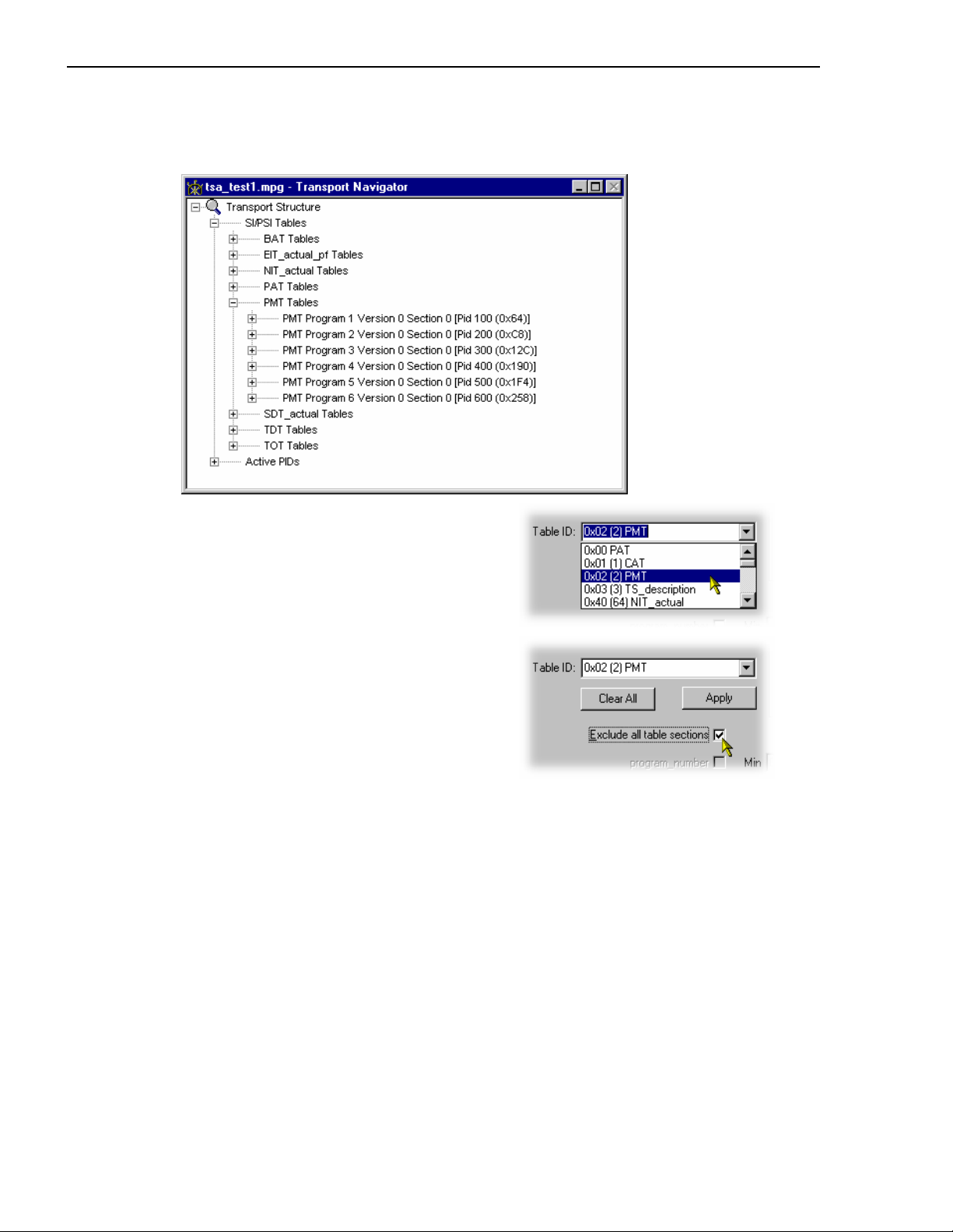
Selecting a Table for Filtering
Example: Prior to filtering, the stream tree may be as shown here:
In the Filter SI Display dialog table identities
are listed in the
Table Id: drop-down menu.
All sections of a table can be excluded by
enabling the
Exclude all table sections
checkbox.
To view the result of filtering, the Refresh
Table Tree
View menu.
option must be selected from the
26 AD951A/AD953A MPEG Test System User Manual
Page 43

Transport Stream Analyzer - 1
In this case the PMT Table Id will still be displayed but all sections will be excluded – as
shown below:
or sections of tables can be included:
To exclude a range of sections, enable the section by selecting the checkbox and enter the
range required.
Note that section names
shown in the dialog change
according to the Table
selected.
To view the result of
filtering, the
Tree
option (or F5) must be
selected from the
Refresh Table
View
menu.
For example, the settings shown here will result in the display shown below:
Minimum and maximum values may be entered in either decimal (12345) or hexadecimal
(0xA12B) format.
AD951A/AD953A MPEG Test System User Manual 27
Page 44

1 - Transport Stream Analyzer
The parameters for each table must be set individually. Overall settings can be applied
individually by selecting the
all of the settings and selecting the
Apply button when a setting is made or as a whole by making
OK button.
To view the result of new filter settings, the
from the
View menu.
All settings can be cleared by selecting the
Note that filter settings remain in force for as long as TS Analyzer is active; filter settings
made for one stream will be applied to all streams subsequently opened. The settings are
lost when TS Analyzer is closed unless they have been previously saved.
Saving/Loading SI Filter Settings
The filter settings made in the Display Filter dialog can be saved and subsequently reapplied to the same stream or other streams.
To save the current filter settings, select the
the
Save As dialog. To retrieve or load filter settings, select the Load button and identify
the filter file in the
Open dialog. The file extension *.fil is used.
Storing SI information
This features speeds up the analysis time where high densities of SI are present. Table data
collected during analysis is stored in volatile memory if the
is enabled. This means that even if filtering is applied, the underlying data is still available.
If the filtering is removed, the data can be successfully displayed. The data is lost when the
stream is closed.
Refresh Table Tree option must be selected
Clear All button.
Save button and enter a name (and location) in
Settings Î Store all SI option
If the
Settings Î Store all SI option is not enabled, full analysis will still take place, but
any Table information which is not displayed because of filter setting will be discarded. If
all sections in a table are filtered, even the Table Id will not be displayed in the Navigator
tree.
28 AD951A/AD953A MPEG Test System User Manual
Page 45
Transport Stream Analyzer - 1
Menus and Controls
When a file is open the program presents a different set of controls. All TS Analyzer
functions can be accessed from the Menu Bar. The Toolbars provide convenient shortcuts
for the more frequently used menu options. All controls are context-sensitive; that is, they
will be enabled or disabled depending on the view currently selected.
Menus and Options
The Menu Bar provides access to all system options via drop-down menus.
A check mark (
no
9 means that it is hidden. Similarly a greyed-out option indicates that the option is not
currently available.
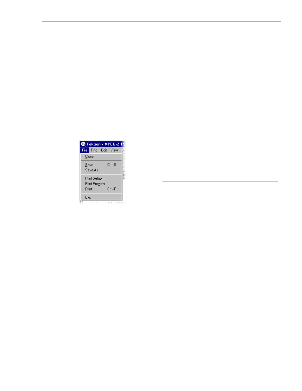
File Menu Options
9) next to an option indicates that the window or toolbar is currently visible,
Close Closes the current file. This option is
available as soon as analysis starts. If
the wrong file is being opened, or the
wrong options are selected, selecting
this option will abandon the analysis
and close the file.
Save Allows the currently highlighted
Transport Navigator view to be saved
in ASCII format. (If the view has not
previously been saved, the Save As…
dialog is displayed so that a file name
can be created.)
Save As… Allows the currently highlighted
Transport Navigator view to be
named and saved in ASCII format.
Print Setup… Selects printer and configuration.
Print Preview Provides an on-screen print preview
of the currently selected view.
Print… Prints contents of the currently
selected view.
Exit Closes any file that is open and
terminates execution the program.
AD951A/AD953A MPEG Test System User Manual 29
Page 46

1 - Transport Stream Analyzer
Find Menu Options
Edit Menu Options
Transport Packet Opens the Find Transport Packet
dialogue, to search using one or
more criteria..
Copy Copies the contents of the current
window to the Windows Clipboard,
from which it can be pasted into a
document in another application.
Paste TS Packet Selecting this option will go to
and display details of the packet
number held by the Windows
clipboard.
(The packet should have already
been identified in the PES Analyzer
and copied to the Windows
clipboard using the
TS packet
option.)
Edit Î Copy
View Menu Options
Options available in this menu are dependent upon the currently selected view.
View Menu Options - All views, basic menu
Toolbars Ź
A sub-menu that provides the Control viewing
options. All options are toggle action. The
following options are available:
Main Views
PCR Graphs View Controls
Slider bar Status bar
(See Toolbars, page 34.)
-----------------------------------------------------------------
All options in this section of the View menu are
toggle action; either showing or hiding the named
view.
Message Log
Shows or hides the Message Log view.
Hex Views Ź
Transport Packet Hex View
Displays the transport packet in
hexadecimal form.
PSI/SI/PSIP Section Hex View
Displays the PSI/SI/PSIP table section in
hexadecimal form.
30 AD951A/AD953A MPEG Test System User Manual
Page 47
Transport Stream Analyzer - 1
Structure Diagrams Ź
Transport Packet Header and
PSI/SI/PSIP Section
Bit Rate Graphs
Transport Bit Rate
PID Bit Rate.
PCR Statistics Ź
Interval; Arrival Time Jitter; Inaccuracy;
Overall Jitter and Frequency Offset
Multiplex Statistics
and
Ź
Histogram and Pie chart view selection.
Module Specific View
Displays a module specific view, e.g. EPG
(Electronic Program Guide). If more than one
module specific view is available, a dialog is
displayed from which a selection can be made.
---------------------------------------------------------------------
Refresh
Refreshes the currently active view (where
appropriate).
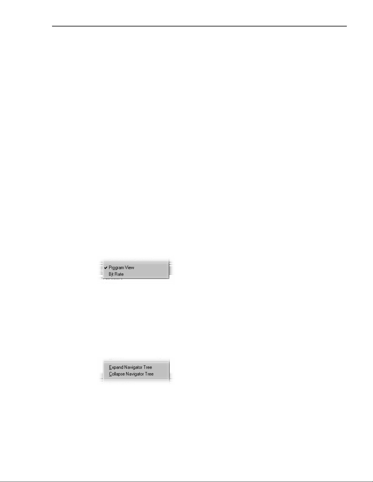
View Menu Options - Multiplex Statistics view (Histogram only)
Program View
Changes the sort order of the PIDs in the
Multiplex Statistics window. When enabled,
the PIDs are sorted by Program and Table
order. When disabled they are sorted by
ascending PID number.
Bitrate
PID usage can be expressed either as a
percentage of the whole stream or in Mbit/s.
View Menu Options - Navigator view
Expand Table Tree
Expands all the nodes in the Transport
Navigator window’s Transport Structure tree.
Collapse Table Tree
Collapses all the nodes in the Transport
Structure tree.
AD951A/AD953A MPEG Test System User Manual 31
Page 48

1 - Transport Stream Analyzer
Graphs Menu Options
Graphs menu options are enabled when a graph view is open.
Settings Menu Options
All Settings dialogs are enabled when no stream is open. With a stream open, all Settings
menu options are enabled except the Tests option; the
Size
dialog boxes are opened in read-only mode.
Synchronise Views
When enabled, automatically synchronises all
displayed PCR graphs.
Zoom In / Out
Zoom in/out the displayed PCR graph.
--------------------------------------------------------------------
Previous Point Differential
Selects PPD plotting in the PCR Statistics
graphs.
Line Fit Differential
Selects LFD plotting in the PCR Statistics
graphs.
Stream Interpretation… and Packet
Tests…
Displays the Test Settings dialog.
Stream Interpretation…
Displays the Stream Interpretation dialog.
Packet Size
Specifies the packet size that will be used to
interpret the stream.
Display Filter…
Displays the Display Filter dialog.
Store all SI
When enabled, all SI information is stored
during analysis. When disabled, SI Information
for tables that are filtered out is not stored.
32 AD951A/AD953A MPEG Test System User Manual
Page 49

Transport Stream Analyzer - 1
Window Menu Options
Cascade Cascades all open windows in TS
Analyzer. Minimized windows are
ignored.
Tile Tiles all open windows
horizontally.
Arrange Icons Aligns icons of any minimised
windows at the bottom of the
program's main window.
1 <window title> Makes the named window
2 <window title> active, putting it on top of any
3
... etc. windows which had been
hiding all or part of it.
Help Menu Options
About StreamAnalyser… Opens a dialog which
displays the program version
number and license number.
AD951A/AD953A MPEG Test System User Manual 33
Page 50

1 - Transport Stream Analyzer
Toolbars
Toolbars provide convenient shortcuts for the more frequently used menu options. The four
toolbars are described in the following paragraphs.
Toolbars can be individually dragged off the edge of the main window into a floating pallet.
To do this place the mouse pointer on the vertical bar at the left-hand end of the toolbar,
hold the left button down and drag into the main window area. The result is a self-contained
window as shown below:
Toolbars can also be docked with any edge of the main TS Analyzer window. To place the
Toolbar on a window border drag it over the border until the outline changes shape.
Main Toolbar
Closes the current file. This button becomes enabled the moment a file is opened
and analysis starts. If the wrong file is being opened, or the wrong options are
selected, clicking on the button will abandon the analysis and close the file.
Open a file. This button is disabled when a file is open.
Saves the contents of the Transport Navigator to a simple text file.
Print the contents of the current window.
Opens the Find Transport Packet dialog to search for a packet by one or more
criteria.
Copies the Message Log to the clipboard.
Opens a dialog that displays the program version number and license number.
34 AD951A/AD953A MPEG Test System User Manual
Page 51

Transport Stream Analyzer - 1
Views Toolbar
Toggles the Message Log view.
Toggles the Transport Packet Hex view.
Toggles the SI Table Section Hex view.
Toggles the Transport Packet Header view.
Toggles the SI/PSI Table view
Toggles the PCR Instantaneous Transport Rate scatter graph.
Toggles the PID Bit Rate graph.
Toggles the Multiplex Statistics (Histogram) view.
Toggles the Multiplex Statistics (Pie Chart) view.
Toggles a module-specific view, e.g. EPG view. If more than one modulespecific view is available a dialog containing a list of available views is
displayed.
PCR Views Toolbar
Toggles the PCR Interval scatter graph.
Toggles the PCR Arrival Time Jitter scatter graph
Toggles the PCR Inaccuracy scatter graph
Toggles the PCR Overall Jitter scatter graph
Toggles the PCR Frequency Offset scatter graph
AD951A/AD953A MPEG Test System User Manual 35
Page 52

1 - Transport Stream Analyzer
View Control Toolbars
Navigator View Control
Status Bar
Message Field
Expands all branches of the
Transport Structure tree in the Transport
Navigator.
Collapses all branches of the
Transport Structure tree in the Transport
Navigator.
Multiplexer Statistics Histogram View Control
Toggles the Multiplex Statistics histogram view between Program view and
PID view.
Toggles the display of the value of the current occupancy of each PID relative
to the other PIDs in either
% or Mb/s.
PCR Graph View Control
Synchronises all PCR graph displays.
Zoom in to PCR graph display.
Zoom out from PCR graph display.
Base Standard
Keyboard Mode
Indicators
Filter Status
Timestamp
status
Analysis
status
The Status Bar may be hidden from view, but if visible is always at the bottom of the main
window. It displays the following information about the program and keyboard states:
Message Field Gives a description of any button or menu option over which
the mouse pointer is placed. It can also show non-critical
messages.
Base Standard Indicates the base standard selected in the Stream
Interpretation dialog.
Keyboard Mode Indicators Indicates the keyboard mode, i.e. CapsLock, NumLock and
ScrollLock.
Filter Status Indicates that the Navigator display Filter is in use, i.e.
On
.
Filter
Timestamp Status Indicates that timestamps have been found in the stream.
Analysis Status Indicates progress when a file is being loaded.
36 AD951A/AD953A MPEG Test System User Manual
Page 53

Transport Stream Analyzer - 1
Slider Bar
The program can display the contents of any packet in the currently loaded file. Packets are
numbered according to their position in the file, the first being packet 0 (zero). The Slider
Bar displays the packet number for the current packet. It has a slider control and buttons for
selecting which packet to view.
Slider
Scrolls through the
packets in the file.
Start of file
Move to
previous packet
End of file
Move to next
packet
Current packet
The left and right cursor movement buttons are shortcuts for the previous and next packet
buttons.
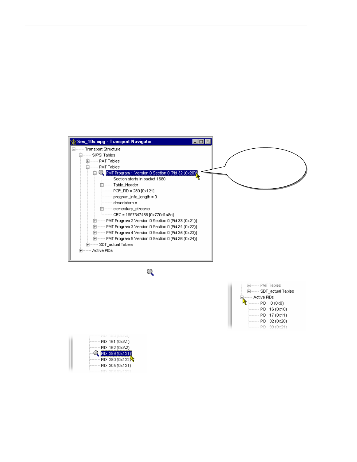
A filter can be specified to restrict which packets the Slider Bar may select. The filter can
be used to select a particular PID and table_id in the table sections of the Navigator tree or a
single PID in the Active PIDs section of the Navigator tree. The current filter selection is
indicated by the magnifying glass symbol,
, in the Transport navigator. A new filter can
be selected by clicking on the required Table or Active PID in the Transport Navigator
window.
Selected Type:
PMT tables
for Program 1
(PID 32)
Clicking on any reference to a PID or table_id will set the filter. For example clicking on
the line ‘
PCR PID = 289 (PID 289 (0x121)’ will restrict selection to packets carrying PID
289.
AD951A/AD953A MPEG Test System User Manual 37
Page 54

1 - Transport Stream Analyzer
When there is no magnifying glass symbol or
Bar may select any packet. To disable filtering, click on the
Transport Structure is selected the Slider
Transport Structure node.
Like the Toolbar, the Slider Bar can be dragged from the edge of the main window into a
floating pallet. To do this click on the background inside the Slider Bar (the label ‘
Packet’
is a convenient place) and drag into the main window area. The result is a self-contained
window which looks like this:
To replace the Slider Bar on the window border drag it over the border until the outline
changes shape. Unlike the Toolbar it can only be placed on either the top or bottom edges.
38 AD951A/AD953A MPEG Test System User Manual
Page 55
Transport Stream Analyzer - 1
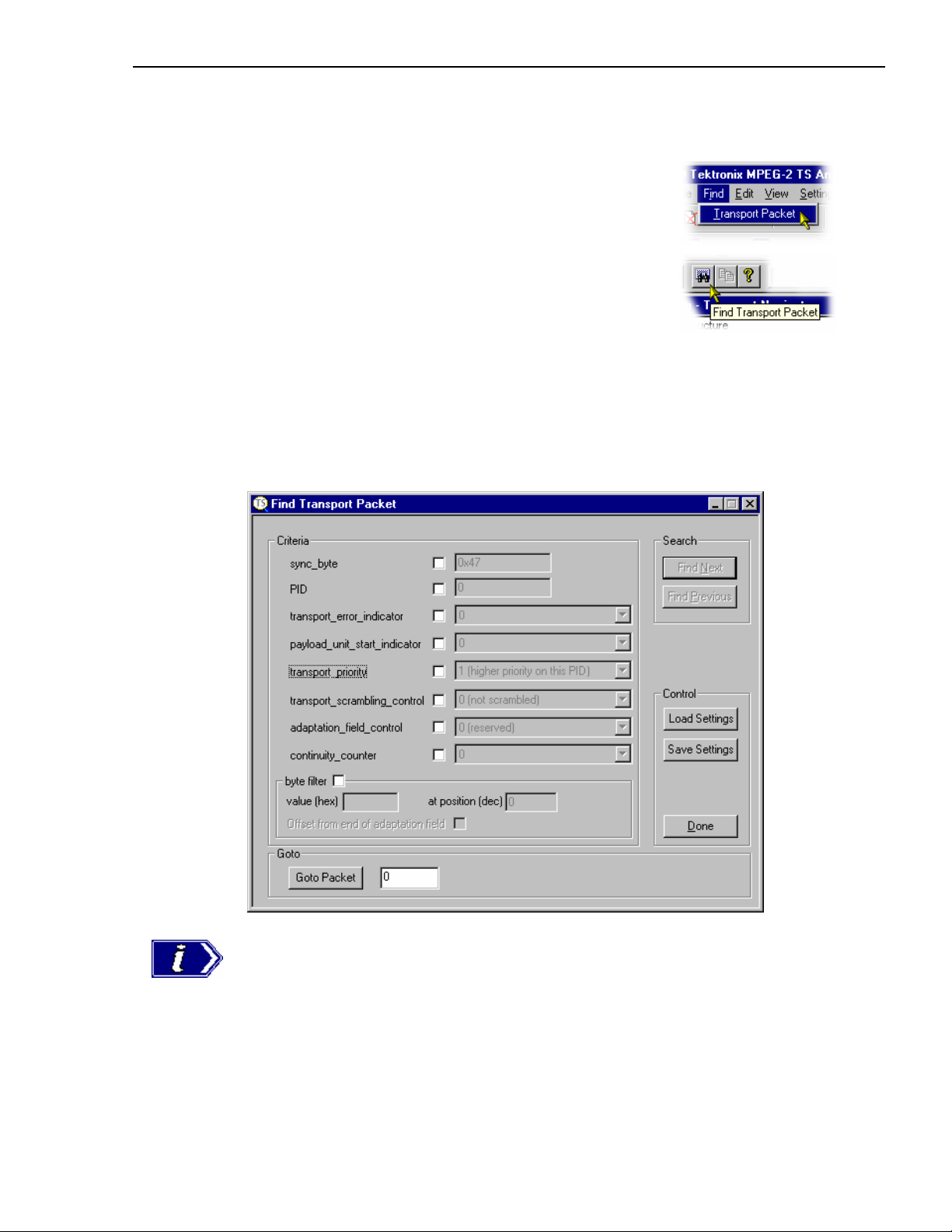
Find Transport Packet
To go to or search for transport packets select the
Transport Packet option from the Find menu.
Alternatively click on the Find Transport Packet
button on the Toolbar:
This opens the Find Transport Packet dialog. Packets can be searched for by any
combination of the Criteria contained in the dialogue. The
its position within the file, taking the first packet as 0 (zero).
Goto facility selects a packet by
By default, when the
Find->Transport Packet option is first selected, none of the criteria
options are selected, the packet number in the
Find Previous buttons are disabled.
Goto panel is 0 (zero), the Find Next and
The Find Transport Packet dialog remains open after a packet has been selected to make it
quicker to select further packets. It may be closed by selecting the
Done button. The dialog
is not confined within the boundaries of the main window. It may be moved on to the
desktop and also minimised on the desktop.
AD951A/AD953A MPEG Test System User Manual 39
Page 56

1 - Transport Stream Analyzer
Search by Criteria
To search for packets which match a set of criteria select the required options in the Criteria
panel. For example, if packets of PID 160 carry MPEG-2 video, to search for packets with
an adaptation field the criteria could be selected as follows:
Click in a checkbox to select a search criteria. Once selected the associated value is no
longer ‘greyed out’ and can be modified. The
decimal or hexadecimal by prefixing the value with
hexadecimal. Select all of the required search criteria and specify the associated values.
Both of the
Find Next to search forward from the current packet or Find Previous to search backwards.
The Byte Filter
The byte filter criteria
provides facilities to
search for packets by the
value at a specific
position in the packet.
Select the byte filter option then enter the search value and position of the byte within the
packet. Enter the search value as a pair of hexadecimal digits. In the above example the
value is 0x7f (that is 127 in decimal). The position is specified as an offset from the first
byte in the packet, the same as the addresses shown in the Transport Packet Hex View. The
first byte of a packet is at position 0 (zero).
When searching for a packet with the
value of
becomes available for selection.
sync_byte and PID values may be entered in
0x. E.g. PID 160 would be 0xA0 in
Find buttons become enabled as soon as one of the criteria is selected. Click on
adaptation_field_control criteria selected and a
3 (payload and adaptation field) the Offset from end of adaptation field option
This option changes the address mode to treat the first byte after the adaptation field as
position 0 (zero). For example:
40 AD951A/AD953A MPEG Test System User Manual
Page 57

Transport Stream Analyzer - 1
To search for packets
which have the value 7
in the 15 byte after an
adaptation field, enter a
value of 07 hex and a
position address of 14
decimal.
Loading and Saving Settings
The current set of search criteria may be saved to disk for reference
and re-use by clicking on the
browser window is opened to specify the name and location of the
settings file.
By default the file has an extension of .fnd
Save Settings button. A standard file
Goto Packet
Select the
Load Settings button to restore a set of previously saved search criteria.
This also opens a
standard file browser
with the default
extension of
.fnd
It is a good idea to
choose names that
explain what the settings
are or give a reminder of
what the search is for.
Transport Stream Analyzer displays the location of a packet within the file on the Slider
Bar. This is the position from the start of the file, numbering the first packet as Packet 0
(zero). To move to a specific packet by this address, enter the packet number and select the
Goto Packet button in the Goto panel. For example:
This will move to packet
108325. If the file is shorter than 108325 packets the program will
stay on the current packet.
AD951A/AD953A MPEG Test System User Manual 41
Page 58

1 - Transport Stream Analyzer
Transport Navigator
Where required, the Transport Navigator performs the following functions:
x Displays structure of the Service Information (SI/DVB) and Program Specific
Information (PSI/MPEG) and Program and System Information Protocol (PSIP/ATSC)
Tables, including their payload information.
x Lists all the Active Packet Identifiers (PID).
x Enables packet selection, via the Slider Bar, to be set to all packets or only those
belonging to a particular PID or PID and table_id.
42 AD951A/AD953A MPEG Test System User Manual
Page 59
Transport Stream Analyzer - 1
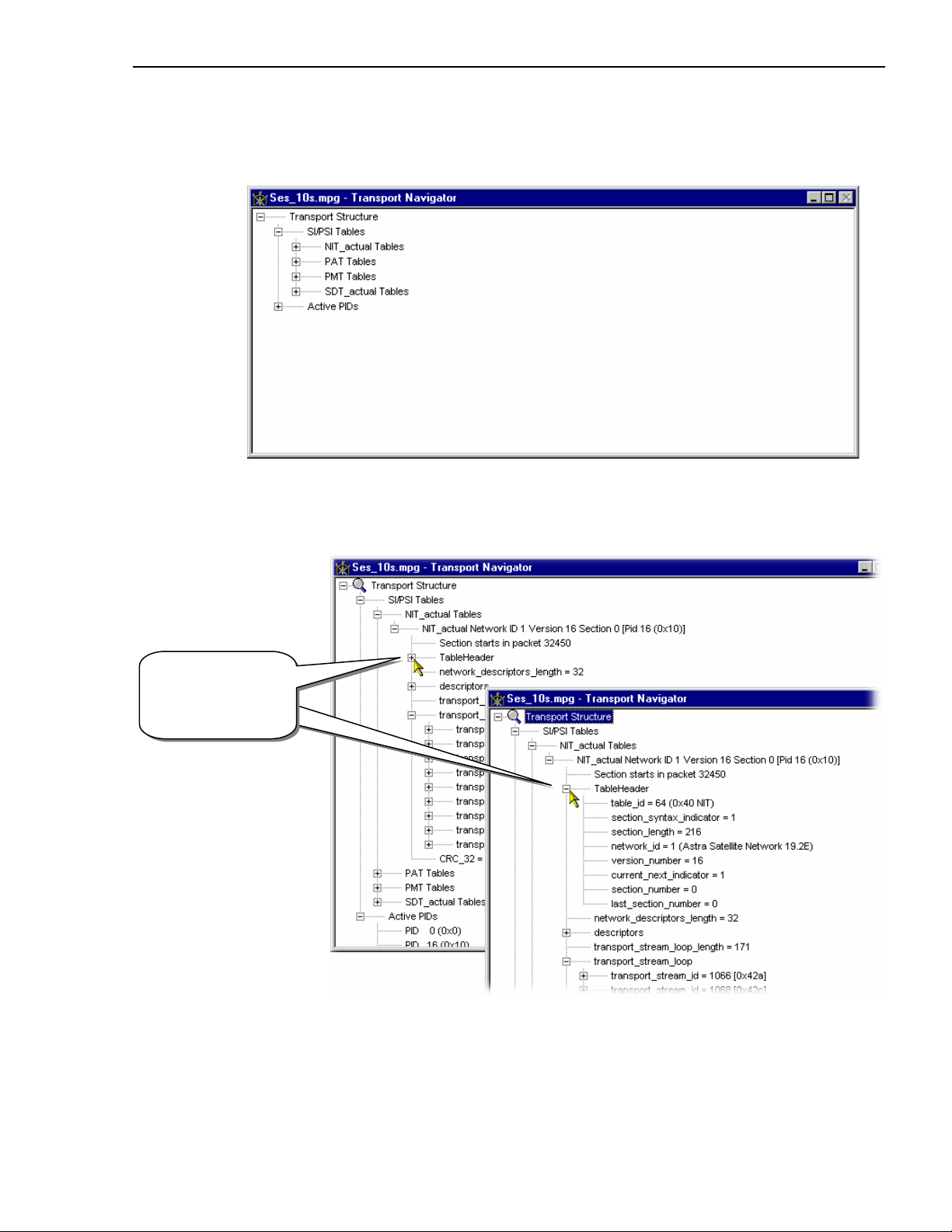
Transport Structure Diagram
The Transport Navigator is displayed by the program as soon as a file is opened. As the file
is analysed the top levels of a structure diagram are drawn in the window:
The structure is represented by a tree diagram, with the ‘root node’ or highest level
component at the top. Components which contain more information beneath them in the
structure are indicated as a branch node by a square box.
Click on the box to
display or hide the
structure beneath
the node.
Click on the
box to
display or
If the branch node has a minus sign in the box the level of detail below it is displayed. The
lower level(s) may be hidden by clicking the mouse pointer on the box.
If the box contains a plus sign, there is another level contained by the node which is
currently hidden. Click the mouse pointer on the box to display the next level of
information under the node.
AD951A/AD953A MPEG Test System User Manual 43
Page 60
1 - Transport Stream Analyzer
Components which are connected to a branch of the tree without a square box are leaf
nodes. They display the lowest and finest level of detail.
Selecting a PID
The Transport Navigator displays Packet Identifiers (PID) as a positive decimal integer
followed by the equivalent hexadecimal value in brackets (parenthesis). The PID is carried
in a 13 bit field hence PID values range from
When a file is first opened and analysed any packet may be selected. The Slider Bar and
Transport Navigator can be used together for restricting selection to packets with a
particular PID and table_id. This is called PID and table_id filtering. A filter can be
specified by clicking on any reference to a PID or table.
0 (0x0) to 8191 (0x1FFF).
Selected Type:
PMT tables
for Program 1
(PID 32)
The magnifying glass symbol,
, on the line indicates the selected PID and table_id.
To select a PID which does not hold table
information or is not referred to in a table do the
following:
Expand the
Active PIDs branch of the Transport
Structure. This gives a list of all the Packet
Identifiers found in the file.
If the list is longer than can be contained in the visible
area of the window a scroll bar will appear. Scroll
down to find the required PID.
Select the line showing the PID number.
44 AD951A/AD953A MPEG Test System User Manual
Page 61

Transport Stream Analyzer - 1
To disable the filter and allow any packet to be selected, click on
root node. When the
Transport Structure node is selected (or the magnifying glass symbol
Transport Structure, the
is hidden) the Slider Bar may select any packet.
Transport Structure
selects all packet types.
No magnifying
glass implies
that all types
are selected.
Refer to the section on the Slider Bar for details of how to select packets once the PID
selection is made.
AD951A/AD953A MPEG Test System User Manual 45
Page 62

1 - Transport Stream Analyzer
Looking at the SI/PSI/PSIP Tables
Table information is carried in the packet payloads. Each table section is carried in packets
identified by a PID unique to that table.
For example:
The Program Association
Table (PAT) is always held
in packets of PID 0 (zero).
The PAT contains
information about which
PIDs in the Transport
Stream are carrying the
Program Map Tables
(PMT).
Under the Version and
Section number the
Transport Navigator
identifies the first packet in
the file holding the PAT
section (
at…
Section starts
).
For sections that do not have
reserved PIDs (e.g. the PMT
which is referenced by the
PAT),
Section starts at…
does not identify the first
packet of the first section in
the file. Instead, it describes
the first packet of the first
section after the PID has
been referenced.
E.g. In the screenshot, the PMT for Program 4167 states Section starts in packet 1721.
This (1721) is actually the first packet number of the section after PMT PID 4167 has been
referenced by the PAT.
Some table sections are so large that their information is split across several packets. In
these cases the transport navigator gives the number of the first packet of that section in the
file with the
payload_unit_start_indicator in the Transport Packet Header set.
Below this the program interprets and displays the contents of the section.
46 AD951A/AD953A MPEG Test System User Manual
Page 63

Transport Stream Analyzer - 1
Table Structure
When a table section has been selected in the Transport Navigator, the SI/PSI Table
Structure window may be opened. This displays the Table contents in an alternative format,
as specified in the MPEG-2 standard ISO/IEC 13818-1, Annex F.
The above example shows a similar PAT to that displayed by the Transport Navigator in the
previous section. The
a large adaptation field, this table will fit in a single packet.
Looking at the Packets
Individual packets containing Table information can be examined using the Transport
Packet Header and Hex View. This is the same PAT section as shown above. Looking at the
first packet in the Hex View confirms that this section fits in a single packet:
Section length is held in this packet
in the byte at address 0x0007, with a
value of 0x21 (33 in decimal).
The last byte of table section
information is at address 0x0028.
From byte 0x002A to 0x00BC the
packet has been filled with packet
stuffing bytes of 0xFF.
The last 16 bytes contain the Reed Solomon data.
If in any doubt open the Transport Packet Header window to check for adaptation fields, as
in the next example.
section length field in the Table Structure shows that, unless there is
AD951A/AD953A MPEG Test System User Manual 47
Page 64

1 - Transport Stream Analyzer
Packets with Adaptation Fields
Packets carrying table sections may also contain an adaptation field. Here is an example of
a Service Description Table (SDT) section where an adaptation field and payload exactly
fill one packet:
Section length
in bytes
The Table Structure shows a section length of 113 bytes. This is the number of bytes after
the
section length field. So the total number of bytes in this payload is 117.
Opening the Transport Packet Header window shows an Adaptation Field of 67 bytes:
Gives number of bytes
following this byte. Total
length of Adaption Field
is 67 bytes
48 AD951A/AD953A MPEG Test System User Manual
Page 65

Transport Stream Analyzer - 1
Adding these together with the 4 bytes of the Header gives a total of 188 bytes:
Header 4
Adaptation Field 67
Payload (Section length + 4 bytes) + 117
188
If the transport stream consists of 204 byte packets the remaining 16 bytes contain the Reed
Solomon data. This is how the packet looks in the Hex View:
AD951A/AD953A MPEG Test System User Manual 49
Page 66

1 - Transport Stream Analyzer
Table Sections spanning two or more packets
A table section may contain more information than can fit in a single packet. Without any
space taken up by an adaptation field a packet has 184 bytes available to hold payload data.
The section of the Network Information Table (NIT) in this example has a section length of
216 bytes:
Number of bytes
after this field
The
section length can be seen in the Transport Navigator as well as the Table View:
Number of bytes
after this field
The payload for this NIT section consists of: 4 bytes of data up to and including the section
length field, plus the 216 bytes following the section length field. A total of 220 bytes. This
spans two packets as follows:
50 AD951A/AD953A MPEG Test System User Manual
Page 67

Transport Stream Analyzer - 1
Packet carrying first byte of table section
Both Table Structure and Transport Navigator identify the first packet in the file which
carries the start of the section. Selecting the Table in the Transport navigator automatically
selects the first packet with a start of section. There may be one or more packets, preceding
that, whose section start was prior to the start of file.
The Slider Bar will allow any packet of the chosen PID to be selected. The Transport Packet
header will show if it carries the start of a packet. For example:
The payload unit start
indicator is set to 1,
hence this packet
should hold the start of
the section
Alternatively, the
packets by PID with a particular
Find Î Transport Packet menu option has facilities to search for
payload_unit_start_indicator value.
The Hex View shows that the packet is completely filled by the section contents. There are
no packet stuffing bytes.
AD951A/AD953A MPEG Test System User Manual 51
Page 68

1 - Transport Stream Analyzer
Subsequent Packet carrying PSI Table section
The next packet, which should contain the remaining 36 bytes of the table section, can be
selected by either:
x Clicking on the Next packet button in the slider bar (providing that table section is still
selected as the current PID in the Transport navigator)
x Using the
payload_unit_start_indicator parameter set to 0 (zero).
Find -> Transport Packet menu option with the
The second packet of the example NIT section looks like this in the Transport Packet
Header and the Hex Views:
52 AD951A/AD953A MPEG Test System User Manual
Page 69

Transport Stream Analyzer - 1
Looking at the Complete Table (Hex View)
The SI Table Hex view displays the complete table in hex format.
AD951A/AD953A MPEG Test System User Manual 53
Page 70

1 - Transport Stream Analyzer
Transport Packet Hex View
This is the lowest level view of the Transport Packet data. It shows the contents of each
byte in hexadecimal on the left and ASCII characters on the right. The ASCII representation
only shows characters for values in the range 0x20 (space) to 0x7e (tilde). All others are
represented by a dot.
Each byte is represented as a pair of hexadecimal digits, in the hexadecimal representation
and a single character in ASCII. The four digit numbers in the left most column are the
addresses, also in hexadecimal, of the first byte of each row. Four example: the sync byte
(value
47) is first in the packet. It is at address 0x0000.
Address of
the first byte in
the row
in this case
the Sync byte
0x4f
shown as
the letter "G" in
ASCII
Note that by using the cursor to highlight a section of data, the corresponding data is
highlighted in the hex or ASCII area.
54 AD951A/AD953A MPEG Test System User Manual
Page 71

Transport Stream Analyzer - 1
Packet Size
The packet size can be
determined from the address of
the last byte. 204 byte packets
go up to address 0x00CC, but
the last address of 188 byte
packets is 0x00BC.
The previous examples are from
a 204 byte packet stream.
This is an example from a 188
byte packet stream:
Packet Header
The first four bytes of the packet contain the Packet Header. The numbers in the Hex View
and characters in the ASCII view are colored magenta to make the header stand out. The
rest of the data, the payload, is displayed in black.
4 byte Packet
Header colour
coded magenta
ASCII view
colour coded
to match
The Transport Stream Analyzer provides the Transport Packet Header view to interpret
information held in headers and adaptation fields.
AD951A/AD953A MPEG Test System User Manual 55
Page 72

1 - Transport Stream Analyzer
Adaptation Fields
If the packet header has an adaptation field, the bytes are shown in blue. This is to make
them stand out from the rest of the header and the payload data.
This particular packet belongs to an MPEG-2 video PID and contains a PCR adaptation
field of 8 bytes. Adaptation fields can be much larger than this.
Transport Private Data
If transport private data is present it is color coded green in both the hexadecimal
representation and ASCII view:
4 byte Packet
Header colour
coded magenta
4 byte header
displayed in magenta
colour text
Adaptation Field
colour coded blue
Adaptation Field
displayed in blue
colour text
Text in ASCII
view colour coded
to match
Transport Private
Data colour coded
green
56 AD951A/AD953A MPEG Test System User Manual
Page 73

Transport Stream Analyzer - 1
r
Transport Packet Header
The Transport Packet Header view interprets and displays the header of the currently
selected packet. The relationship of the information displayed to the Hex View and
underlying binary data is shown in this diagram:
Transport
Packet
Heade
Binary
Hexadecimal
Hex View
AD951A/AD953A MPEG Test System User Manual 57
Page 74

1 - Transport Stream Analyzer
Adaptation Fields
If the packet contains an adaptation field the Transport Packet Header view will interpret
and show information which is defined in the MPEG-2, DVB and ATSC standards. It will
not interpret private data, whose format is not in the public domain.
This is a Transport Packet Header view of an adaptation field containing a Program Clock
Reference (PCR):
and this is the mapping between Transport Packet Header and Hex Views:
58 AD951A/AD953A MPEG Test System User Manual
Page 75

Transport Stream Analyzer - 1
Message Log
The program always displays the Message Log window when it opens a file. As the file is
analysed the program reports the results, listing errors and warnings, in this window. Once
analysis is complete, a summary is appended to the report.
The following icons are used to indicate the activity logged:
Information Indicates processing activity.
Time Indicates the time of an activity.
Warning Provides information about low severity events.
Error Provides information about high severity events and
conformance violations.
AD951A/AD953A MPEG Test System User Manual 59
Page 76
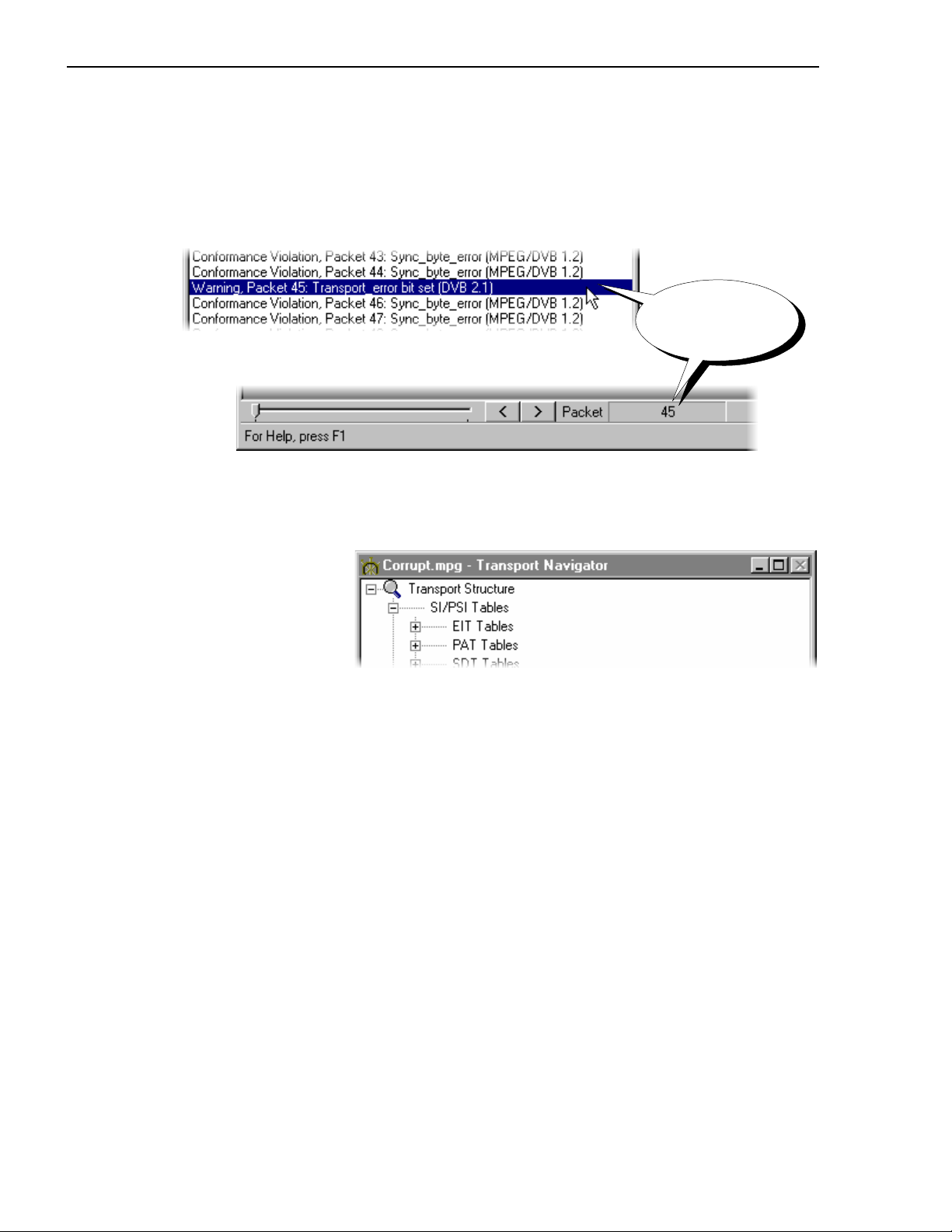
1 - Transport Stream Analyzer
Packet Selection
If a warning or error message gives a packet number, that packet may be inspected by
selecting the message. For example, here is an extract from a Message Log which contains
reports of errors and warnings, i.e. a series of conformance violations for packets 43, 44,
46,47 and a warning for Packet 45:
Any PID selection in the Transport navigator will be reset to allow all PIDs to be accessed.
The magnifying glass icon will appear on the
structure diagram:
Selecting this line
makes Packet 45 the
current packet.
Transport Structure at the top level of the
60 AD951A/AD953A MPEG Test System User Manual
Page 77

Transport Stream Analyzer - 1
Having selected the packet it can now be inspected with other tools, such as, the Transport
Packet Header and Hex View.
Raw header
information shown in
hexadecimal and colour
coded magenta
State of transport error
indicator is interpreted in
the Transport Packet
Header window
Grey may be used if the last bytes
are missing from the transport
stream; in such a case, the missing
bits would be set to 00.
AD951A/AD953A MPEG Test System User Manual 61
Page 78

1 - Transport Stream Analyzer
Multiplex Statistics
Two views of the multiplex statistics are available. Each view shows essentially the same
information, one as a histogram, the other as a pie chart. They show what proportion of the
Transport Stream is taken up by each PID, across the entire file. There are various display
options available in the histogram view.
Histogram View
Program View
When Transport Stream Analyzer is first started Program View is selected by default. This
displays the PIDs listed in program number order, then by PID number within each
program. The tables and non-program PIDs follow the programs in the list.
If there are more PIDs than can be displayed a scroll bar will appear on the right hand side
of the window.
From left to right the columns displayed in Program View are:
Program For program streams this displays the program number and type of
data carried by each PID. The data types are:
Video PID carries packets of video
Audio PID carries packets of audio
62 AD951A/AD953A MPEG Test System User Manual
Page 79

Transport Stream Analyzer - 1
AC3 Audio PID carries packet of ATSC compressed audio
Priv PID carries Private data
UPriv PID carries User Private data
For non-program PIDs a name or mnemonic is given if it can be
determined from the relevant tables. Any PID carrying unrecognised
data type is left blank.
PID Shows the PID number which each row of the table applies to.
% or Mbits/s Displays the current occupancy of each PID relative to the other PIDs
as a value. The selected units of measurement,
% or Mbits/s, is
displayed in the column title.
Use the
Multiplex Occupancy Shows the current occupancy of each PID relative to the other PIDs
Selecting Program View
To switch to Program View, if it is not currently selected, click on the
Program View option from either the right-click menu (right) or from
the
View menu (below):
Bitrate option from the pop-up Menu to toggle between the
% and Mbits/s display.
as a bar chart.
(A check mark 9 appears next to the option when Program View is selected. No check
mark indicates that PID View is selected.)
AD951A/AD953A MPEG Test System User Manual 63
Page 80

1 - Transport Stream Analyzer
PID View
The PID View displays the PIDs, in PID number order, without program numbers or types.
To select PID view, uncheck the
menus.
Using the same file as for the previous Program View example, the PID View is:
Program View option in either the View or right-click
From left to right the columns displayed in Program View are:
PID Shows the PID number to which each row of the table applies.
% or Mbits/s Displays the current occupancy of each PID relative to the other PIDs
as a value. The selected units of measurement,
% or Mbits/s, is
displayed in the column title.
Multiplex Occupancy Shows occupancy of each PID relative to the others as a bar chart.
64 AD951A/AD953A MPEG Test System User Manual
Page 81

Transport Stream Analyzer - 1
Right-Click Menu
This menu provides display options and a refresh command. Position the cursor anywhere
inside the window and click the right mouse button to display the menu.
Bitrate Display
When the Bitrate option is selected from the right-click menu the % or Mbits/s column
displays the occupancy figures in Mbit/s. For example:
(A check mark, 9,
indicates that the
display option is
currently enabled.)
Program View
Selects Program or PID view. (A check mark, 9,
indicates that Program View is selected. No check
mark, 9, means that PID view is displayed.)
Bitrate Toggle the % or Mbits/s column between
displaying values as a percentage or bit rate. (A
check mark, 9, indicates that the values are given
as a bit rate. No check mark, 9, means that they are
shown as a percentage.)
Refresh If a stream is still being analysed this option
refreshes the display to show the latest results.
Once analysis is complete, and the final results are
displayed, this option has no further effect.
AD951A/AD953A MPEG Test System User Manual 65
Page 82

1 - Transport Stream Analyzer
Double Clicking for Additional Information
Once the analysis of the file is complete some more information can be displayed by double
clicking on the bar or text for a PID. This causes the program to display a pop-up window
showing additional information. Single or double clicking the mouse elsewhere removes the
pop-up window.
Double clicking provides the same information in both the Program View and PID View.
66 AD951A/AD953A MPEG Test System User Manual
Page 83
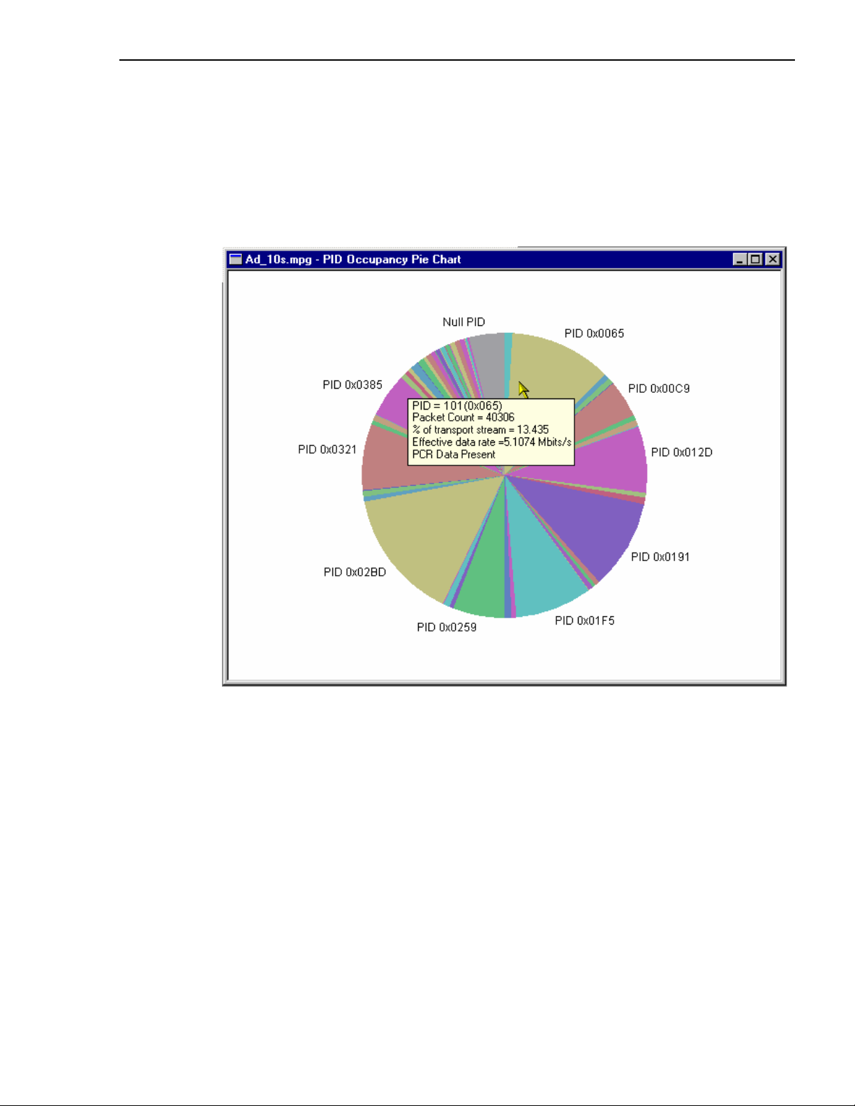
Transport Stream Analyzer - 1
Pie Chart View
This Multiplex Statistics window displays a pie chart that shows what proportion of the
Transport Stream is taken up by each PID, across the entire file.
More information can be displayed by double-clicking a section of the pie chart. This
causes the program to display a pop-up window showing additional information for that
PID. The information displayed is the same as that shown in the histogram view.
AD951A/AD953A MPEG Test System User Manual 67
Page 84

1 - Transport Stream Analyzer
Graphing Features
The Transport Stream Analyzer program checks the Program Clock References (PCR) for
conformance to the DVB, ATSC and MPEG-2 standards. It analyses the timing of the PCRs
and displays interpretations of these results using the PCR Statistics Graphs.
There are two sets of graphs: PCR Statistics and Bit Rate. All graphs have a similar format
and controls. The common features are as follows:
PID
selection
buttons
Point Data
Display Area
Cursor
Slider Bar
PID Selection Buttons
Down the left hand side of the window are one or more buttons for selecting which PIDs to
plot on the graph. In the above example there are 5, of which PID 610 and PID 620 are
displayed in the graph.
Display Area
All points are color coded to match the color of their selection button, i.e. the points for PID
610 are colored the same blue as the top of the PID 610 button.
68 AD951A/AD953A MPEG Test System User Manual
Page 85

Transport Stream Analyzer - 1
Cursor
The cursor indicates the point to which the current data applies.
Note the crosshair box at the actual data point.
(See also Slider Bar below.)
Horizontal (Time) Axis
The horizontal axis of the graph represents time, as related to the position of the packet
within the file. The file starts at the left-hand side and finishes at the right.
Vertical Axis
The vertical axis is specific to each type of graph. The scale may be recalibrated when a
PID is added to the graph (button selected) or removed (button deselected).
Point Data
The data associated with a selected point is displayed in the Point Data table. The point can
be selected by clicking the cursor over the required point or by using the Slider Bar.
Bitrate Point Data Table
PCR Statistics Point Data Table
Note that not all values are relevant to all of the graphs described in the following pages.
Where not relevant, the value will be marked as 'not applicable' or the field will not be
displayed.
Zoom Controls
For each press of a plus or minus Zoom button, the x axis is scaled by
approximately ±50%.
AD951A/AD953A MPEG Test System User Manual 69
Page 86

1 - Transport Stream Analyzer
PCR Synchronise
Plot Format
The points on the PCR_AC, PCR_OJ and Arrival Time Jitter PCR graphs can be plotted
using one of two measurement methods: Previous Point Differential and Line Fit
Differential. The technical aspects of these methods are described in an on-line Technical
note accompanying this User Guide.
When enabled, this function automatically synchronises all displayed PCR
and bitrate graphs in terms of displayed PIDs, cursor position and zoom level.
The values are taken from the active PCR and applied to all open PCR and
bitrate graphs.
The plot method is selected via the
Graphs menu.
As a guide, the two illustrations below show the same section of a file in the PCR
Inaccuracy graph using the
Previous Point Differential and Line Fit Differential (default)
methods respectively.
Previous Point Differential Line Fit Differential
70 AD951A/AD953A MPEG Test System User Manual
Page 87

Transport Stream Analyzer - 1
Slider Bar
The Slider Bar represents the position of the currently selected point in the file, the section
of the file currently displayed and allows the selection to be changed.
Previous/Next
point
Cursor
Cursor
Pointer
File Range
Zoom Range
The whole bar represents the whole file or File Range. The black section of the bar, the
Zoom Range, represents the displayed section; this will change according to the zoom
selection.
The Cursor Pointer indicates the position of the cursor in the file/zoom range. The cursor
can be moved in the following ways:
x Click the mouse pointer in the display area. The Cursor will move to the nearest point
and details will be shown in the Data table. The Slider Bar will also reflect the change of
position.
x Use the mouse pointer to drag and drop the Cursor Pointer in the Slider Bar. If the
pointer is dragged outside the current Zoom Range, the Zoom Range (and hence the
display) will be moved to centre the cursor in the display area.
x Click the mouse pointer to the left or right of the Cursor Pointer.
x Use the Previous/Next point buttons. Each press of a button will move the Cursor to the
previous/next point of the currently selected PID.
AD951A/AD953A MPEG Test System User Manual 71
Page 88

1 - Transport Stream Analyzer
PCR Statistics Graphs
PCR Interval
This graph provides a display of the time interval between successive PCRs. The
interval is displayed on the y-axis. By default the y-axis scale shows the conformance
thresholds for the DVB, ATSC or MPEG-2 standards.
To conform to MPEG-2 the interval must be within 100ms. For conformance to DVB or
ATSC the interval must be within 40ms. If the interval exceeds the 100ms threshold, the yaxis scale will be adjusted accordingly.
72 AD951A/AD953A MPEG Test System User Manual
Page 89

Transport Stream Analyzer - 1
Arrival Time Jitter (Arrival)
(Also known as Network Jitter.) This graph displays the time interval between the
actual arrival time of a PCR packet and its expected arrival time based on its byte index.
The actual arrival time is calculated using time stamping information appended to each
packet when a transport stream is recorded with the Player application with Time-Stamping
active. Note that the ASI+TS card must be fitted for the time-stamping feature to be
available. Only time-stamped streams can be graphed in this way.
Arrival Time Jitter = PCR_OJ - PCR_AC
(For more information about Arrival Time Jitter, refer to Appendix I of Reference [1].)
AD951A/AD953A MPEG Test System User Manual 73
Page 90

1 - Transport Stream Analyzer
Inaccuracy (PCR-AC)
The Inaccuracy graph shows the difference between the actual and expected
values for each PCR on the y-axis. Expected PCR values are calculated from the byte index
of the PCR.
PCR_AC = PCR_OJ - Arrival Time Jitter
The MPEG-2, DVB and ATSC standards specify that PCRs must be within ±500ns of the
actual transport rate. By default the scale is set to ±500ns. If the Inaccuracy in any of the
displayed PIDs is greater than ±500ns, the y-axis is drawn to show the complete range of
values as full scale.
(For more information about PCR_AC, refer to Section 5.3.2.6 and Appendix I of
Reference [1].)
74 AD951A/AD953A MPEG Test System User Manual
Page 91

Transport Stream Analyzer - 1
Overall Jitter (PCR-OJ)
The Overall Jitter graph shows the time interval between the actual value of the
PCR and its expected value based on its arrival time.
The actual arrival time is calculated using time stamping information appended to each
packet when a transport stream is recorded with the Player application with Time-Stamping
active. Note that the ASI+TS card must be fitted for the time-stamping feature to be
available. Only time-stamped streams can be graphed in this way.
PCR_OJ = PCR_AC + Arrival Time Jitter
This value can be compared against the maximum error specification in ISO/IEC 13818-1
for PCR Accuracy of ±500 ns only if the jitter in the transmission is assumed to be zero.
(For more information about PCR_OJ, refer to Section 5.3.2.5 and Appendix I of
Reference [1].)
AD951A/AD953A MPEG Test System User Manual 75
Page 92
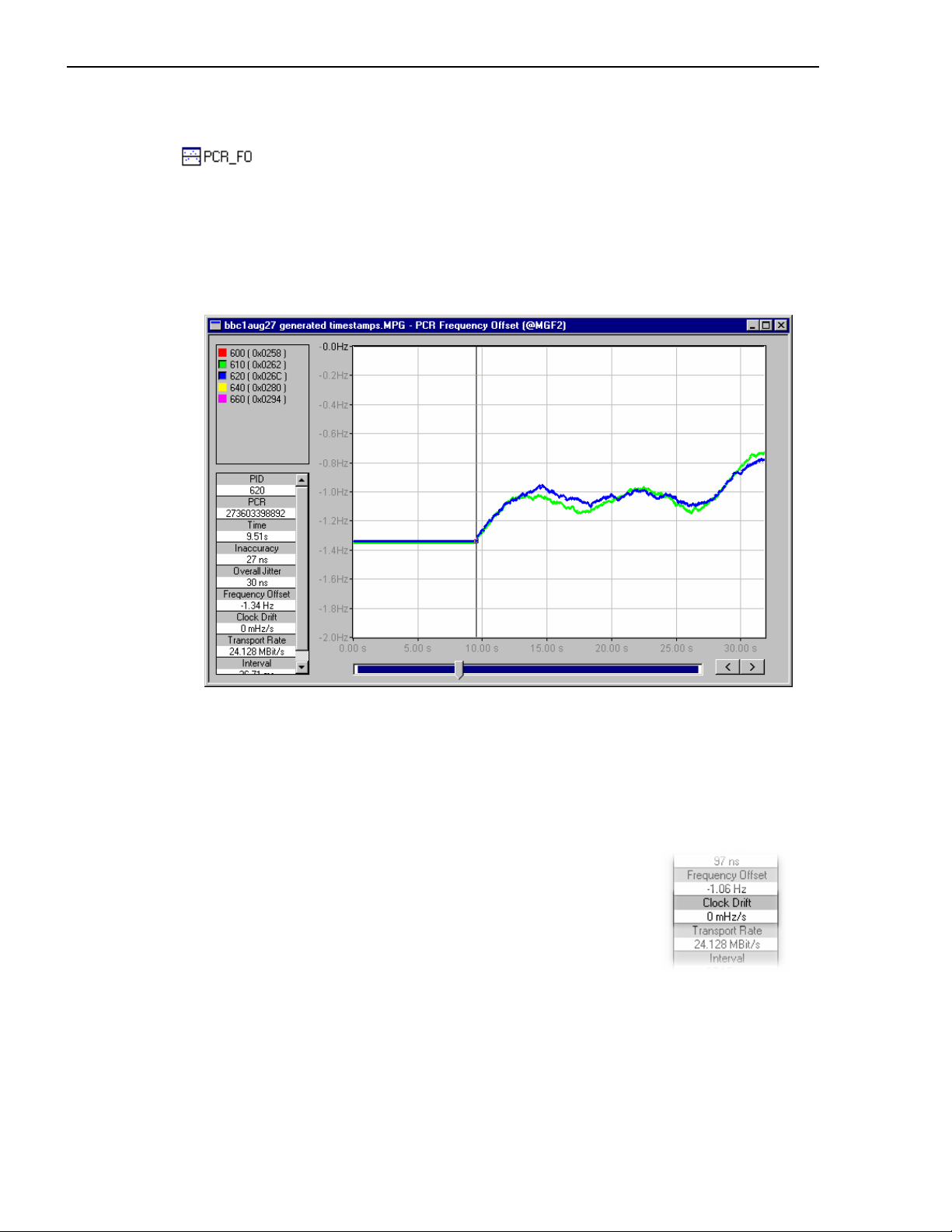
1 - Transport Stream Analyzer
Frequency Offset (PCR-FO)
The Frequency Offset graph shows the difference between the program clock
frequency and the nominal clock frequency (measured against a reference which is not PCR
or TS derived).
The frequency is calculated using time stamping information appended to each packet when
a transport stream is recorded with the Player application with Time-Stamping active. Note
that the ASI+TS card must be fitted for the time-stamping feature to be available. Only
time-stamped streams can be graphed in this way.
PCR_FO is a measurement of the error in the PCR frequency from the specified 27MHz;
the MPEG specification sets the limits at ±810Hz.
(For more information about PCR_OJ, refer to Section 5.3.2.3 and Appendix I of
Reference [1].)
PCR Drift Rate Measurement (PCR_DR)
This value (Clock Drift) is shown in the data table for a selected
point. It is the rate of change PCR_FO and is usually very small.
Since it is calculated using PCR_FO measurements, it is only
available for time-stamped transport streams.
(For more information about PCR_OJ, refer to Section 5.3.2.4 and Appendix I of
Reference [1].)
76 AD951A/AD953A MPEG Test System User Manual
Page 93

Transport Stream Analyzer - 1
Bit Rate Graphs
Instantaneous Transport Rate (ITR)
This graph displays the instantaneous transport rate on the y-axis. It is derived
from each pair of PCRs and displayed in the form of a scatter graph centred around the
mean transport rate for the file. Each point on the scatter graph represents the rate for a
particular PCR.
Following are some more examples from streams synthesised for Tektronix. They show
different ranges and patterns in the data:
AD951A/AD953A MPEG Test System User Manual 77
Page 94

1 - Transport Stream Analyzer
PID 110 is constant and PID 210 has a small sinusoidal variation, both centred on 8.0
Mbit/s.
PID 310 has a slightly bigger range, going from 7.9998 to 8.0001 Mbit/s. When added to the
graph the range and other data is rescaled.
78 AD951A/AD953A MPEG Test System User Manual
Page 95

Transport Stream Analyzer - 1
Adding PID 410 to the display changes the scales more. Because of the peak values of
PID 410, PIDs 310 and 210 now occupy a smaller proportion of the scale.
The vertical line in this graph shows a discontinuity of some sort. This may have been
caused by a large step in the PCR values. The general area can be determined by inspecting
and analysing the PCRs on either side of the discontinuity.
AD951A/AD953A MPEG Test System User Manual 79
Page 96
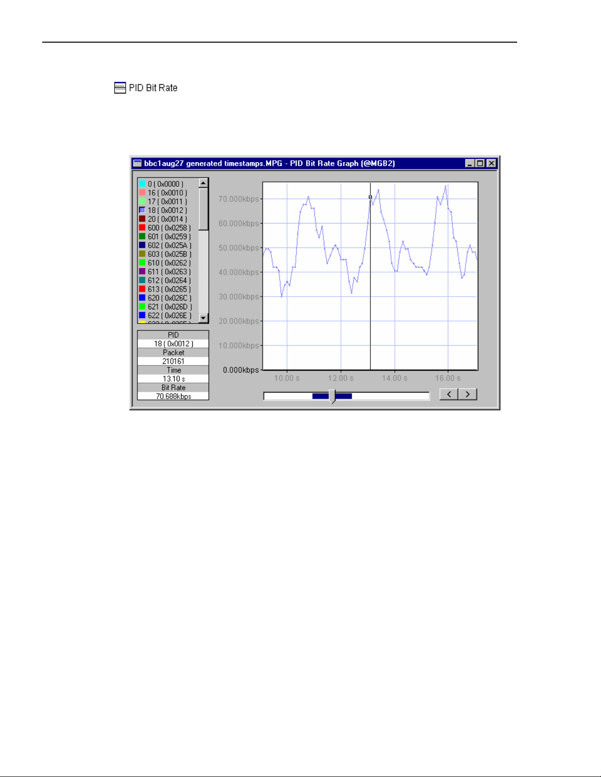
1 - Transport Stream Analyzer
PID Bitrate
specified PID over a particular interval (defined by MGB2, refer to section 5.3.3.2 in
reference [1]). The bitrate can be calculated for each PID in the stream. The bitrate for each
PID is calculated on-demand; a progress bar is displayed. If the
during calculation of the bitrate, the partial results are displayed in the graph window.
PID bitrate is calculated by counting the number of packets that occur on a
Stop button is selected
80 AD951A/AD953A MPEG Test System User Manual
Page 97

Transport Stream Analyzer - 1
)
Electronic Program Guide
The Electronic Program Guide view (EPG), available in DVB, ATSC or ISDB mode, is a
module-specific view. Information, extracted from the Service and Event SI/PSIP tables, is
used to compile a graphical display.
To open the EPG view, select
View Î Module Specific View. If more than one module-
specific view is available, a dialog is displayed from which the required view can be
selected.
Actual/Other
Schedule Select
Day SelectTime Select
Schedule window
Normal event (Bl)
Date Select
Time Zone Select
Overlapping
events (Or)
Zoom
Controls
Service
header
Present
event (Gr)
Following
event (Y)
CRC error (R)
Timescale (24hr
(Note that the codes given in the bottom left-hand corner of each
schedule item in this diagram are given for color reference only
and do not appear on the actual display.)
In the EPG example shown above, the current time is between 13:00 and 14:00 hours, as
implied by those events marked as 'Present'.
AD951A/AD953A MPEG Test System User Manual 81
Page 98

1 - Transport Stream Analyzer
The screen elements are described below:
Actual/Other The DVB, ATSC and ISDB-S standards describe two types of
The EPG can show only one schedule (Actual or Other) at a time.
Time Select If the time selected in this field is not currently displayed, the display
Day Select A DVB and ISDB schedule may contain schedules for up to 64 days;
Date Select This field provides an alternative way to select the day (of those that
Time Zone Select The time zone may either be derived from the transport stream, UTC
schedule information, i.e. the schedule for the Services transmitted in
the transport stream - Actual, and the schedule for Services not
carried in the transport stream - Other.
will immediately scroll until it is.
the ATSC schedule is 16 days long. This field is used to select the
day to be displayed. Note that only one day can be displayed at a
time.
may be available) to be viewed. Note that the value in the Day select
field is changed to match the date selected.
(Co-ordinated Universal Time) or local time (as set on the host
computer).
Zoom Controls Zooms in or out on the day currently displayed by approximately
50%.
Note that currently the EPG view will only display events in the H-layer when in ISDB-T
mode.
82 AD951A/AD953A MPEG Test System User Manual
Page 99
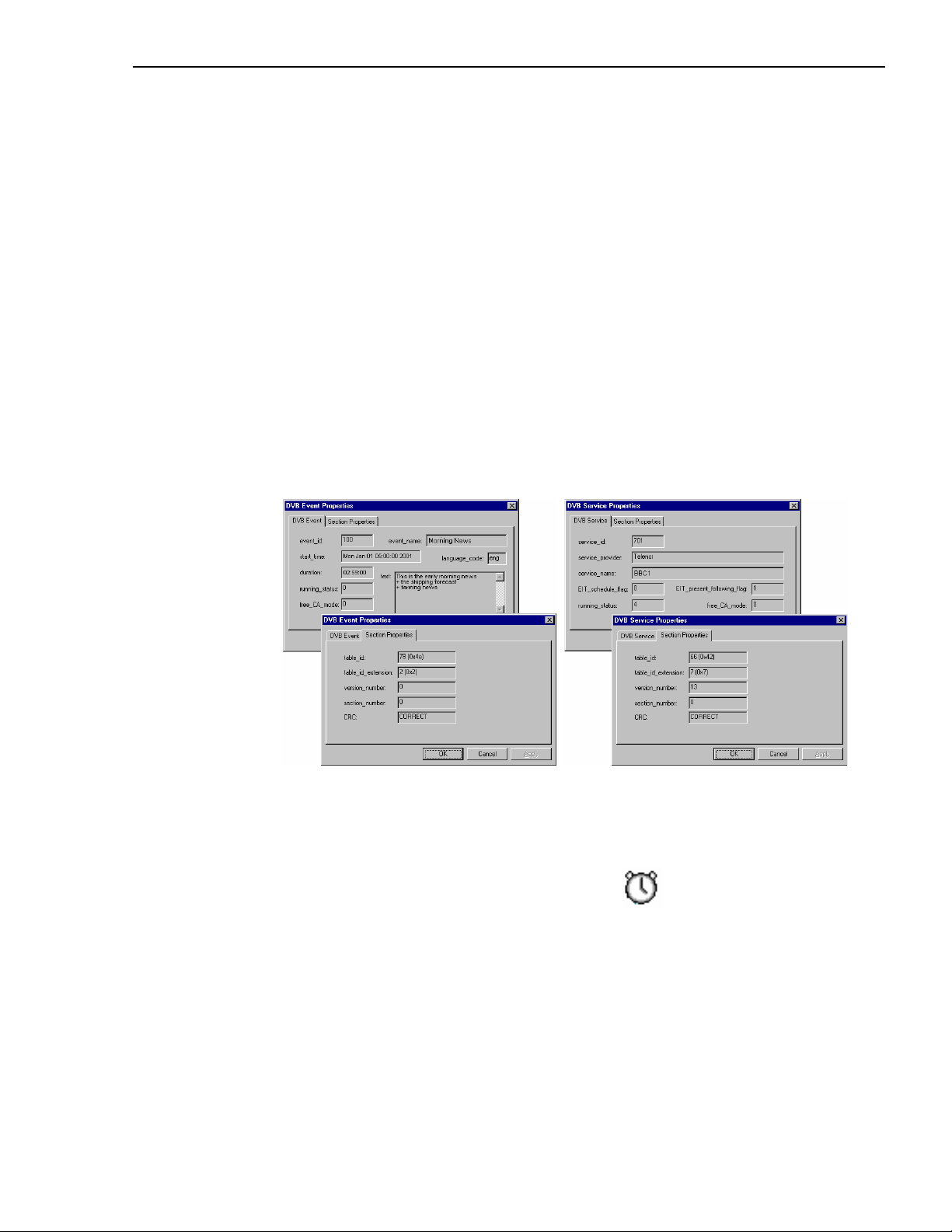
Transport Stream Analyzer - 1
Schedule Window
The main area or Schedule window of the EPG window displays all of the events scheduled
for a single day in the selected schedule (Actual or Other).
Each event described by the Event Information Table is displayed in graphical form and
associated with a Service. Included in each event block are the event name and the timing of
the event. In the case of present or following events, an appropriate label is also displayed
(DVB and ISDB only).
Event Properties
Double-clicking on an individual event or a service header in the schedule window will
display a properties dialog. The fields displayed in the two tab pages of this dialog are
derived from the EIT and SDT (DVB and ISDB) or the EIT and MGT (ATSC).
The content of the first page (left-hand tab) will vary depending on whether the item is an
event or a service and whether it is time-shifted or not. The second page (right-hand tab)
always displays Section Properties since both services and events, whether time-shifted or
not, are always carried in sections.
(Examples of DVB Event properties)
Time-Shifting
A service or event may be displayed with a clock icon ; this indicates that the item is
'time-shifted'.
AD951A/AD953A MPEG Test System User Manual 83
Page 100

1 - Transport Stream Analyzer
Color Coding
The status of the events is color coded for easy recognition:
Green: Present Event - An event which is signalled as the Actual or Other event
currently being broadcast (DVB and ISDB only).
Yellow: Following Event - An event which is signalled as the Actual or Other event to
be broadcast after the Present Event (DVB and ISDB only).
Blue: Normal Event - A normal, scheduled event that does not fall into any other
category.
Red: CRC Error - The event was transmitted in a section with a bad CRC (cyclic
redundancy check).
Orange: Overlapped Event - An event's duration overlaps with another event.
84 AD951A/AD953A MPEG Test System User Manual
 Loading...