


Technical Reference
AD951A & AD953A
MPEG Test System
Specifications and Performance Verification
071-1425-00
Warning
The servicing instructions are for use by qualified
personnel only. To avoid personal injury, do not
perform any servicing unless you are qualified to
do so. Refer to all safety summaries prior to
performing service.
www.tektronix.com

Copyright © Tektronix, Inc. All rights reserved.
Tektronix products are covered by U.S. and foreign patents, issued and pending. Information in this publication supercedes
that in all previously published material. Spec ifications and price change privileges reserved.
Tektronix, Inc., P.O. Box 500, Beaverton, OR 97077
TEKTRONIX and TEK are registered trademarks of Tektronix, Inc.

Table of Contents
General Safety Summary iii...................................
Specifications
Related Manuals 1--1.................................................
Product Description 1--2..............................................
Electrical Specifications 1--3...........................................
Mechanical Characteristics 1--11........................................
Environmental Characteristics 1--12......................................
Certificates and Compliances 1--13.......................................
Performance Verification
Preparation 2--1.....................................................
Check ASI+TS Interface 2--5....................................
Check the Player 2--5.................................................
Check the Monitor 2--9...............................................
Check the Recorder 2--12..............................................
Check SMPTE 310M Interface (SSI) 2--17..........................
Check the Player 2--17.................................................
Check the Monitor 2--22...............................................
Check the Recorder 2--24..............................................
Check DVB SPI Interface 2--29...................................
Check the Player 2--29.................................................
Check the Monitor 2--33...............................................
Check the Recorder 2--35..............................................
Test SM+ Duplex (AD953A or AD951A with Option MPLUS) 2--42............
Power Down 2--46....................................................
AD951A & AD953A MPEG Test System Specifications and Performance Verification
i

Table of Contents
ii
AD951A & AD953A MPEG Test System Specifications and Performance Verification

General Safety Summary
Review the following safety precautions to avoid injury and prevent damage to
this product or any products connected to it.
To avoid potential hazards, use this product only as specified.
Only qualified personnel should perform service procedures.
While using this product, you may need to access other parts of the system. Read
the General Safety Summary in other system manuals for warnings and cautions
related to operating the system.
ToAvoidFireor
Personal Injury
Use Proper Power Cord. Use only the power cord specified for this product and
certified for the country of use.
Connect and Disconnect Properly. Do not connect or disconnect probes or test
leads while they are connected to a voltage source.
Ground the Product. This product is grounded through the grounding conductor
of the power cord. To avoid electric shock, the grounding conductor must be
connected to earth ground. Before making connections to the input or output
terminals of the product, ensure that the product is properly grounded.
Observe All Terminal Ratings. To avoid fire or shock hazard, observe all ratings
and markings on the product. Consult the product manual for further ratings
information before making connections to the product.
Do not apply a potential to any terminal, including the common terminal, that
exceeds the maximum rating of that terminal.
Powering Off. The power cord provides Mains disconnect.
Replace Batteries Properly. Replace batteries only with the same type and rating.
Do Not Operate Without Covers. Do not operate this product with covers or panels
removed.
Use Proper Fuse. Use only the fuse type and rating specified for this product.
Avoid Exposed Circuitry. Do not touch exposed connections and components
when power is present.
Wear Eye Protection. Wear eye protection if exposure to high-intensity rays or
laser radiation exists.
Do Not Operate With Suspected Failures. If you suspect there is damage to this
product, have it inspected by qualified service personnel.
Do Not Operate in Wet/Damp Conditions.
AD951A & AD953A MPEG Test System Specifications and Performance Verification
iii

General Safety Summary
Do Not Operate in an Explosive Atmosphere.
Keep Product Surfaces Clean and Dry.
Provide Proper Ventilation. Refer to the manual’s installation instructions for
details on installing the product so it has proper ventilation.
Symbols and Terms
Terms in this Manual. These terms may appear in this manual:
WARNING. Warning statements identify conditions or practices that could result
in injury or loss of life.
CAUTION. Caution statements identify conditions or practices that could result in
damage to this product or other property.
Terms on the Product. These terms may appear on the product:
DANGER indicates an injury hazard immediately accessible as you read the
marking.
WARNING indicates an injury hazard not immediately accessible as you read the
marking.
CAUTION indicates a hazard to property including the product.
Symbols on the Product. The following symbols may appear on the product:
CAUTION
Refer to Manual
iv
AD951A & AD953A MPEG Test System Specifications and Performance Verification
WARNING
High Voltage
Protective Ground
(Earth) Terminal
Standby

Specifications
This chapter contains specifications for the AD951A and AD953A MPEG Test
Systems
All specifications are guaranteed unless labeled “typical.” Typical specifications
are provided for your convenience but are not guaranteed. Specifications marked
with the n symbol are verified in the Performance Verification section.
To meet specifications, the following conditions must be met:
H The system must have been calibrated/adjusted in an ambient temperature
between 20 °C and 30 °C(68°F and 86 °F).
H The system must be kept within the environmental limits specified in this
document.
H The system must be powered from a source maintaining voltage and
frequency within the limits described in this document.
H The system must have been operating continuously for at least 20 minutes
within the specified operating temperature range.
Related Manuals
NOTE. This system’s product calibration classification is List 2; no calibration
data reports are available. However, all measurement equipment used to
establish or verify conformance of the product with published specifications is
maintained traceable.
The following manuals are also available to use with the AD951A and AD953A
MPEG Test Systems. These manuals are shipped with each system, and are also
available on the Tektronix Web site.
H AD951A & AD953A MPEG Test System Getting Started Manual,
071-1422-xx, which provides system installation and operating instructions.
H AD951A & AD953A MPEG Test System User Manual, 071-1423-xx, which
provides detailed reference information about the system.
AD951A & AD953A MPEG Test System Specifications and Performance Verification
1- 1

Specifications
Product Description
The AD951A or AD953A MPEG Test Systems are MPEG Test Systems that
play, record and multiplex MPEG--2 Transport Streams. The AD953A also
includes a protocol analyzer capable of analyzing transport streams in MPEG--2,
DVB, ATSC and ISDB environments. With the addition of Option RM, the
systems can be rack mounted.
AD953A System
AD951A System
The base AD953A system includes one MIC card and one SCSI hard drive for
MPEG file storage. The base system includes the following software:
H Record and Play
H MUX
H Make seamless
H Cutter
H Maker
H Editor
H TSA
H PES and Buffer Analysis
H Monitor Plus
The AD951A system is in the same physical platform as the AD953A and also
has one MIC card and one SCSI hard drive for MPEG file storage. The base
system includes the following software:
1- 2
Options
H Record and Play
H MUX
H Make seamless
H Cutter
H Maker
H Editor
Several software and hardware options can be purchased to add functionality to
the system. For a complete list of options, refer to the AD951A & AD953A
MPEG Test System Getting Started Manual.
AD951A & AD953A MPEG Test System Specifications and Performance Verification

Electrical Specifications
Specifications
Table 1- 1: Platform characteristics
Characteristic Description
Operating system Microsoft Windows NT 4.0, Service pack 6a
Processor P4, 2.53 GHz minimum
Disk space
Operating system and software appli c ations 80 GB, IDE hard drive
MPEG file storage
With one MIC card installed
With two MIC cards installed
MPEG storage disk I/O Port SCSI--3, Micro D68 connector, 68 pin
RAM 1GB
CD--ROM drive DVD--R only / CD--R/W
Floppy disk drive 3.5 in, 1.44 MB high density double--sided
Display LCD, 1024 X 768, 10.4 inches
Ethernet One 10/100--base T; RJ45 connector and
Keyboard port Mini DIN, PS--2, one on the rear and one on
Mouse port Mini DIN, PS--2, one on the rear and one on
Printer port IEEE P1284
EXT VGA Output 15--pin, high density, Sub--D
COM port RS--232
36 GB, one SCSI hard drive
72 GB, two SCSI hard drives
(2HD)
one 10/100/1000--base T; RJ45 connector
the left front side.
the left front side.
AD951A & AD953A MPEG Test System Specifications and Performance Verification
1- 3

Specifications
MIC Board Characteristics
Table 1- 2: Pin allocation of the 15 pin I/O connector
Characteristic Description
Pin 1 Ground
Pin 2 External Clock Input +
Pin 3 Not used
Pin 4 Precision Clock Output –
Pin 5 Not used
Pin 6 Trigger Output
Pin 7 Ground
Pin 9 External Clock Input –
Pin 10 Ground
Pin 11 Precision Clock Output +
Pin 12 Not used
Pin 13 Not used
Pin 14 Trigger Input
Pin 15 Not used
Table 1- 3: Precision clock output characteristics
Characteristic Description
Frequency range 31.25 kHz minimum
12.5 MHz maximum
Resolution 1 bps
n Accuracy ᐔ1 ppm above 2.5 Mbps
ᐔ2 ppm below 2.5 Mbps
Drift, typical ᐔ1 ppm per year maximum typical.
Can be adjusted to remove the drift.
Signal level at BNC output 1.045 V minimum
1.155 V maximum
Into 50 Ω load
Signal level at 15--pin sub D connector LVDS levels into 100 Ω differential load
1- 4
AD951A & AD953A MPEG Test System Specifications and Performance Verification

Table 1- 4: External clock input characteristics
Characteristic Description
Frequency 31.25 kHz minimum
90 MHz maximum
Duty cycle 50% --50% nominal
45%--55% maximum
Signal level of BNC input 200 mV minimum
5.0 V maximum
Triggers on falling edge
Minimum slope of 7.5 V/ s
Input impedance of BNC input 50 Ω
AC coupled
Signal level of 15 pin sub D--connector
clock input
Input impedance of 15 pin sub D--connector clock input
200 mV
2.4 V
LVDS levels
100 Ω differential
p-p
maximum
p-p
minimum
Specifications
Table 1- 5: Trigger input/output characteristics
Characteristic Description
Input signal level VIL: 0 V minimum, 0.8 V maximum
VIH: 2.4 V minimum, 5 V maximum
Output signal level VIL: 0 V minimum, 0.8 V maximum
VIH: 2.4 V minimum, 5 V maximum
AD951A & AD953A MPEG Test System Specifications and Performance Verification
1- 5

Specifications
Table 1- 6: DVB parallel interface characteristics
Characteristic Description
DVB Parallel Input
Connector D--25
n Transport stream rate 250 kbps minimum
90 Mbps maximum
Packet length 188 and 204 byte
Physical interface type LVDS
Signal amplitude 5.0 V
200 mV
Termination 100 Ω line to line of differential pair
Clock period for recording 85 ns minimum
100 s maximum
DVB Parallel Output
Connector D--25
Physical interface type LVDS
Signal amplitude, typical 600 mV ty pical, differential into 100 Ω load
5.0 V maximum differential
maximum differential
p--p
minimum differential
p--p
1- 6
AD951A & AD953A MPEG Test System Specifications and Performance Verification

ASI Interface Card
Characteristics
Specifications
Table 1- 7: ASI input
Characteristic Description
Connector BNC
Link rate 270 Mbaud ᐔ100 ppm
n Transport stream rate 250 kpbs minimum
90 Mbps maximum
Data format ASI format: accepts both burst and packet mode
M2S (DIVICOM)
Signal amplitude 200 mV
2.0 V
Termination 75 Ω nominal, transformer coupled
p--p
maximum
p--p
minimum
Table 1- 8: ASI output
Characteristic Description
Connector BNC
Impedance 75 Ω nominal, transformer coupled
n Transport stream rate 250 kpbs minimum
90 Mbps maximum
Signal amplitude 720 mV
880 V
Into 75 Ω load
p--p
maximum
p--p
minimum
AD951A & AD953A MPEG Test System Specifications and Performance Verification
1- 7

Specifications
GPSI Interface Card
Characteristics
Table 1- 9: SMPTE310M input
Characteristic Description
Connector BNC
Termination 75 Ω, transformer coupled
Data format Bi--phase coded
Compliant with SMPTE310M
Input bit rate 1 Mbps minimum
44 Mbps maximum
Signal amplitude 200 mV
5.0 V
p--p
maximum
p--p
minimum
Table 1- 10: SMPTE310M out put
Characteristic Description
Connector BNC
Output impedance 75 Ω, transformer coupled
Output bit rate Adjustable from 1 Mbps to 44 Mbps
When set for 8VSB 19,392,658.46 bps ᐔ2.8 ppm
When set for 16VSB 38,785,316.92 bps ᐔ2.8 ppm
Signal amplitude 800 mV
1.0 V
p--p
maximum
p--p
nominal
Into 75 Ω load
Table 1- 11: SSI input
Characteristic Description
Connector BNC
Termination 75 Ω, transformer coupled
Data format Bi--phase coded
NRZ data
n Input bit rate 1 Mbps minimum
44 Mbps maximum
Signal amplitude 200 mV
5.0 V
p--p
maximum
p--p
minimum
1- 8
AD951A & AD953A MPEG Test System Specifications and Performance Verification

Table 1- 12: SSI output
Characteristic Description
Connector BNC
Output impedance 75 Ω, transformer coupled
n Output bit rate 1 Mbps minimum
44 Mbps maximum
Signal amplitude 800 mV
1.0 V
p--p
maximum
p--p
nominal
Into 75 Ω load
Table 1- 13: RS422/RS485 input
Characteristic Description
Data format NRZ
Termination 120 Ω line to line of differential pair
Input bit rate 1 Mbps minimum
40 Mbps maximum
Signal amplitude 200 mV
10.0 V
minimum differential
p--p
maximum differential
p--p
Specifications
Table 1- 14: RS422/RS485 output
Characteristic Description
Data format NRZ
Output impedance 120 Ω line to line of differential pair
Output bit rate 1 Mbps minimum
40 Mbps maximum
Signal amplitude 600 mV
5.0 V
Into 120 Ω differential load
p--p
maximum
p--p
nominal
AD951A & AD953A MPEG Test System Specifications and Performance Verification
1- 9

Specifications
Table 1- 15: ECL input
Characteristic Description
Data format NRZ
Coupling Can be configured to be AC or DC coupled
n Input bit rate 1 Mbps minimum
50 Mbps maximum
Signal amplitude 200 mV
5.0 V
p--p
maximum
p--p
minimum
Table 1- 16: ECL output
Characteristic Description
Data format NRZ
Coupling Can be configured to be AC or DC coupled
n Output bit rate 1 Mbps minimum
50 Mbps maximum
Signal amplitude 800 mV
1.0 V
p--p
maximum
p--p
nominal
Table 1- 17: DHEI input
Characteristic Description
Data format NRZ
Coupling DC coupled, differential pair, ECL levels
Input bit rate 1 Mbps minimum
50 Mbps maximum
Signal amplitude 200 mV
5.0 V
p--p
maximum
p--p
minimum
Table 1- 18: DHEI output
Characteristic Description
Data format NRZ
Coupling DC coupled, differential pair, ECL levels
Output bit rate 1 Mbps minimum
50 Mbps maximum
48 Mbps maximum when using external clock
Signal amplitude 800 mV
p--p
nominal
1- 10
AD951A & AD953A MPEG Test System Specifications and Performance Verification

AC Power Source
Characteristics
Table 1- 19: AC power source characteristics
Characteristic Description
Source voltage 100 to 240 VAC ᐔ10% (90 to 264 VAC RMS)
Frequency range 50/60 Hz
Power consumption 4 Amps maximum
Peak inrush current 13 Amp at 240 VAC, 50 Hz
Mains fuse value T6.3AH, 250V, Fast; Not operator replaceable.
Mechanical Characteristics
Specifications
105 watts typical
120 watts typical with Option DU installed
Refer servicing t o qualified service personnel.
Table 1- 20: Mechanical characteristics
Characteristic Description
Classification Fixed location benchtop or rack-mounted use.
Cooling airflow Intake is from t he front and sides of the instrument.
Exhaust is to the bottom and rear of the instrument.
For proper cooling, at least two inches (5.1 cm) of
clearance is needed on the rear and sides of the
instrument cabinet.
Overall dimensions Height 226 mm (8. 9 in), without bottom feet
Width: 432 mm (17 in)
Depth: 560 mm (22 in), with rear feet
Weight 15.5 kg (34 lb)
Shipping weight 27 kg (59.5 lb)
AD951A & AD953A MPEG Test System Specifications and Performance Verification
1- 11

Specifications
Environmental Characteristics
Table 1- 21: Atmospherics
Characteristic Description
Temperature
Operating 5 °Cto40°C, 30 °C per hour maximum gradient
Non--operating --20 °Cto+60°C, 30 °C per hour maximum gradient
Humidity
Operating 10% to 80% relative humidity up to 31 °C. Above 31 °C,
Non--operating 10% to 95% relative humidity, non--condensing
Altitude
Operating 0 to 3000 m (9800 ft)
Non--operating 0 to 12,000 m (40,000 ft)
derate linearly to 50% at 40 °C
Table 1- 22: Dynamics
Characteristic Description
Random vibration
Operating 0.27 grms total from 5 to 500 Hz
Non--operating 2.28 grms total from 5 to 500 Hz
Sine vibration
Operating 0.013 inch peak--to--peak displacement 5 to 55 Hz
Functional shock
Non--operating 20 g, 11 ms half--si ne
Table 1- 23: Transportation and storage in the shipping container
Characteristic Description
Transportation package material Transportation package material meets recycling criteria as
described in Environmental Guidelines for Package Design
(Tektronix part number 063-1290-00) and Environmentally
Responsible Packaging Handbook (Tektronix part number
063-1302-00).
1- 12
AD951A & AD953A MPEG Test System Specifications and Performance Verification

Certificates and Compliances
g
gyp
Table 1- 24: Certifications and compliances
Category Standards or description
Specifications
EC Declaration of Conf ormity -EMC
Australia / New Zealand
Declaration of Conformity-EMC
EC Declaration of Conf ormity -Low Voltage
U.S. Nationally Recognized
Testing Laboratory Listing
Canadian Certification CAN/CSA C22.2 No. 1010.1 : 1992 and No. 1010.1B : 1997
Additional Compliance ANSI/ISA S82.02.01:1999 Safety standard for electrical and electronic test, measuring,
Installation (Overvoltage)
Category Descriptions
1
Emissions which exceed the levels required by this standard may occur when this equipment is connected to a test
object.
Meets intent of Directive 89/336/EEC for Electromagnetic Compatibility. Compliance was
demonstrated to the following specifications as listed in the Official Journal of the European
Communities:
EN 61326 EMC requirements f or Class A electrical equipment for
measurement, control and laboratory use.
IEC 61000--4--2 Electrostatic discharge immunity (Performance criterion B)
IEC 61000--4--3 RF electromagnetic field immunity (Performance criterion A)
IEC 61000--4--4 Electrical fast transient / burst immunity (Performance criterion B)
IEC 61000--4--5 Power line surge immunity (Performance criterion B)
IEC 61000--4--6 Conducted RF immunity (Performance criterion A)
IEC 61000--4--11 Voltage dips and interruptions immunity (Performance criterion B)
EN 61000--3--2 AC power line harmonic emissions
EN 61000--3--3 Flicker
Complies with EMC provision of Radiocommunications Act per the following standard(s):
AS/NZS 2064.1/2 Industrial, Scientific, and Medical Equipment: 1992
Compliance was demonstrated to the following specification as listed in the Official Journal of the
European Communities:
Low Voltage Directive 73/23/EEC, amended by 93/68/EEC
EN 61010-1 : 2001 Safety requirements for electrical equipment for measurement
control and laboratory use.
UL61010B-1 : 2003 Equipment for measurement use.
Safety requirements for el ectrical equipment for measurement,
control, and laboratory use.
controlling, and related equipment.
IEC61010-1:2000 Safety requirements for electrical equipment for measurement,
control, and laboratory use.
Terminals on this product may have different installation (overvoltage) category designations. The
installation categories are:
CAT III Distribution-level mains (usually permanently connected). Equipment at this level is
typically in a fixed industrial location.
CAT II Local-level mains (wall sockets). Equipment at this level includes appliances, portable
tools, and similar products. Equipment is usually cord-connected.
CAT I Secondary (signal level) or battery operated circuits of electronic equipment.
1
AD951A & AD953A MPEG Test System Specifications and Performance Verification
1- 13

Specifications
Table 1- 24: Certifications and compliances (cont.)
Category Standards or description
Overvoltage Category Overvoltage Category II (as defined in IEC 61010-1)
Pollution Degree Descriptions A measure of the contaminat es that could occur in the environment around and within a product.
Typically the internal environment inside a product is considered to be the same as the external.
Products should be used only in the environment for which they are rated.
Pollution Degree 1 No pollution or only dry, nonconductive pollution occurs. Products in
this category are generally encapsulated, hermetically sealed, or
located in clean rooms.
Pollution Degree 2 Normally only dry, nonconductive pollution occurs. Occasionally a
temporary conductivity that is caused by condensation must be
expected. This location is a typical office/home environment.
Temporary condensation occurs only when the product is out of
service.
Pollution Degree 3 Conductive pollution, or dry, nonconductive pollution that becomes
conductive due to condensation. These are sheltered locations
where neither temperature nor humidity is controlled. The area is
protected from direct sunshi ne, rain, or direct wind.
Pollution Degree Pollution Degree 2 (as defined in IEC 61010-1). Note: Rated for indoor use only.
Equipment Type Test and measuring
Safety Class Class 1 (as defined in IEC 61010-1) -- grounded product
1- 14
AD951A & AD953A MPEG Test System Specifications and Performance Verification

Performance Verification
Before you begin the Performance Verification procedures, perform the
following steps:
Preparation
H Ensure that the procedures are performed only by qualified service personnel
who have read the General Safety Summary at the front of this manual.
H Ensure that the service personnel are familiar with system operation (refer to
the AD951A & AD953A MPEG Test System Getting Started Manual).
Required Equipment
H A test system (can be either one of these two systems):
H AD953A with options ASPT, GPPC, and DU installed
H AD953 with ASPT, GPPC, and DU installed
Connect the Systems
Power On
H 75 Ω BNC-to-BNC cable (quantity of four)
Tektronix part number 174-4954-00
H DB25 to DB25 cable (quantity of four)
Tektronix part number 174-4955-00
Connect the following on both the test system and the system under test:
1. Make sure the dongle is securely installed on the parallel port.
2. Connect the keyboard to the side or rear panel keyboard connector.
3. Connect the mouse to the side or rear panel mouse connector.
4. Connect the power cord to the rear panel power input connector.
5. Connect the test system to the unit under test as shown in Figure 2--1.
1. Power on both systems by pushing the front panel ON/STBY switch.
2. When the Microsoft NT window appears, press CTRL-ALT-DEL to bring up
the login window and then click OK.
AD951A & AD953A MPEG Test System Specifications and Performance Verification
2- 1

Performance Verification
Test system
System under test
Power
1 2 3 4 5 6 7 8 9 10 11 12
Parallel
port
Keyboard
Mouse
Power
12 345 6789101112
Figure 2- 1: Connecting the test equipment to the unit under test
Parallel
port
Keyboard
Mouse
2- 2
AD951A & AD953A MPEG Test System Specifications and Performance Verification

Load Test Streams
Performance Verification
1. Load the test streams onto the system as follows:
a. Insert the AD951A and AD953A MPEG Test System Recovery
CD--ROM (Tektronix part number 063-3744-xx) into the CD-RW
drive of the test system.
b. Launch Windows Explorer.
c. Locate the Test Streams directory on the CD-ROM (D: drive) and
run Setup.exe.
d. Follow the setup instructions, accepting all of the default values.
e. Verify that all of the mpg files on the disc were copied to the Test
Streams folder on the E: drive.
f. If there are two MIC cards installed, copy the “Test Streams” folder
from the E: drive to the F: drive.
g. Close Windows NT Explorer.
AD951A & AD953A MPEG Test System Specifications and Performance Verification
2- 3

Performance Verification
2- 4
AD951A & AD953A MPEG Test System Specifications and Performance Verification

Check ASI+TS Interface
Perform these checks only if you have an ASI card installed in your system.
Before you proceed, perform the preparation steps beginning on page 2--1.
NOTE. Each screen, button, or window is illustrated the first time it appears.
Check the Player
System Under Test
1. Launch the player by double-clicking the TS Player icon.
2. Click the Change Interface icon as shown below:
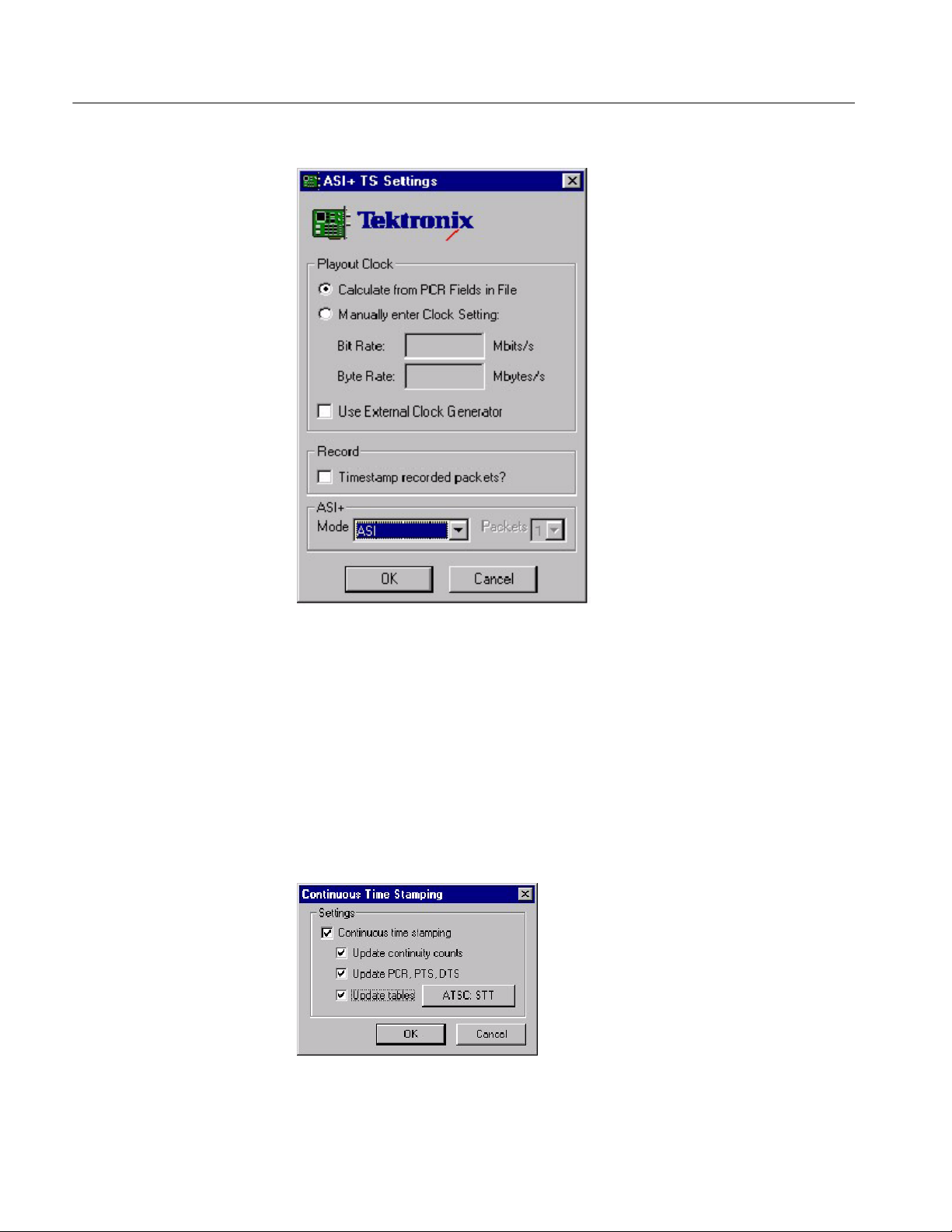
3. Select ASI+TS on the card that is connected to the ASI.
4. Click Settings...
5. In the Settings window, select Calculate from PCR Field in File.
AD951A & AD953A MPEG Test System Specifications and Performance Verification
2- 5
Check ASI+TS Interface
6. Close the Settings window and the Card Configuration window.
7. In the MPEG--2 Player menu:
a. Select File > Open and open the Sym1.mpg file (on drive F).
b. Enable Settings > Auto Rewind.
c. Enable Settings > Loop Mode.
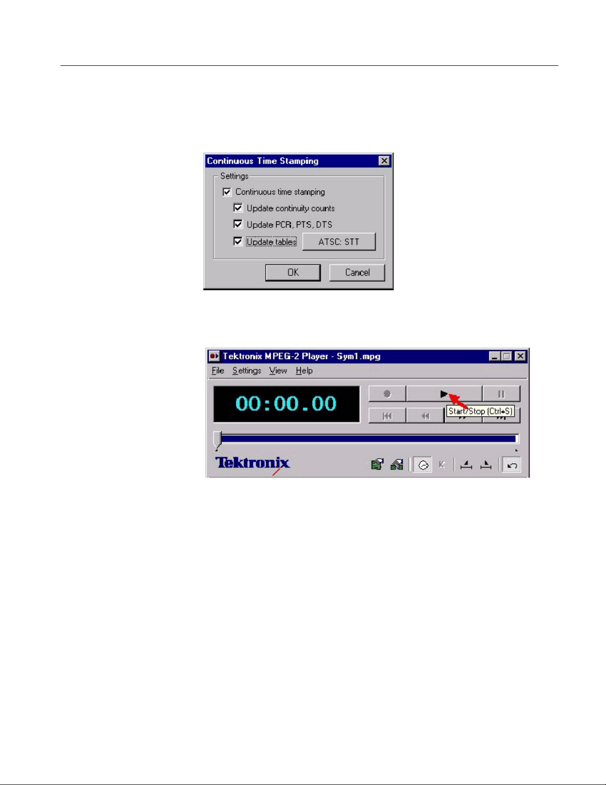
d. Select Settings > Continuous Time Stamping... and enable all options in
that window.
8. Click the play button.
2- 6
AD951A & AD953A MPEG Test System Specifications and Performance Verification

Check ASI+TS Interface
Test System
1. Double-click the TS Monitor-Recorder icon to launch the monitor.
2. Click the change interface icon, as shown below:
3. Select ASI+TS for the card that is connected to the ASI.
4. Set Settings > Mode to Monitor.
5. Click the play button, as shown below.
6. Verify that the monitor displays a green sync indicator and that the sync
errors are zero.
AD951A & AD953A MPEG Test System Specifications and Performance Verification
2- 7

Check ASI+TS Interface
7. Click the toggle multiplex icon, as shown below.
2- 8
AD951A & AD953A MPEG Test System Specifications and Performance Verification

Check the Monitor
Check ASI+TS Interface
Test System
1. Launch the player by double-clicking the TS Player icon.
2. Click the Change Interface icon.
3. Select ASI+TS on the card that is connected to the ASI and then click
Settings...
4. In the Settings window, select Calculate from PCR Field in File.
5. Close the Settings window and the Card Configuration window.
6. In the MPEG--2 Player menu:
a. Select File > Open and open the Sym1.mpg file (on drive F).
b. Enable Settings > Auto Rewind.
c. Enable Settings > Loop Mode.
7. Select Settings > Continuous Time Stamping... and enable all options in that
window.
8. Click the play button.
AD951A & AD953A MPEG Test System Specifications and Performance Verification
2- 9

Check ASI+TS Interface
9. Verify that the multiplexer is displaying the picture information.
2- 10
System Under Test
1. Double-click the TS Monitor-Recorder icon to launch the monitor.
2. Click the change interface icon.
3. Select ASI+TS for the card that is connected to the ASI.
4. Set Settings > Mode to Monitor.
5. Click the play button.
6. Click the toggle multiplex icon.
AD951A & AD953A MPEG Test System Specifications and Performance Verification

Check ASI+TS Interface
7. Verify that the multiplexer is displaying the picture information.
Second ASI Card
Close
If there is a second ASI card installed, repeat the procedure.
Select the stop button (next to the play button) to stop both applications. Then
close both applications by clicking the X in the upper right corner.
AD951A & AD953A MPEG Test System Specifications and Performance Verification
2- 11

Check ASI+TS Interface
Check the Recorder
Test System
System Under Test
1. Launch the ASI player by double-clicking the TS Player icon.
2. Click the Change Interface icon.
3. Select ASI+TS on the card that is connected to the ASI and then click
Settings...
4. In the Settings window, select Calculate from PCR Field in File.
5. Close the Settings window and the Card Configuration window.
6. In the Player menu:
a. Select File > Open and open the Sym1.mpg file (on drive F).
b. Enable Settings > Auto Rewind.
c. Enable Settings > Loop Mode.
7. Select Settings > Continuous Time Stamping... and enable all options in that
window.
1. Double-click the TS Monitor-Recorder icon to launch the monitor.
2. Click the change interface icon.
3. Select ASI+TS for the card that is connected to the ASI.
4. Set Settings > Mode to Monitor.
5. Select File > Create File...
2- 12
AD951A & AD953A MPEG Test System Specifications and Performance Verification

Check ASI+TS Interface
6. The Stream Make Wizard opens. In this window, click Next>.
7. Enter the filename “E:\Test Streams\test.mpg”
8. Set the packet size to 204 Byte Packets.
AD951A & AD953A MPEG Test System Specifications and Performance Verification
2- 13

Check ASI+TS Interface
9. Set the number of packets to 1500000. Click Finish.
10. Set the Settings > Mode to Trigger.
11. Select Settings > ASI+ TS Settings...and enable Timestamp recorded
packets.
2- 14
12. Select File > Set Output and open E:\Test Streams\test.mpg.
13. Select Settings > Mode Settings...to open the Settings window.
AD951A & AD953A MPEG Test System Specifications and Performance Verification

Check ASI+TS Interface
14. In the Settings window, do the following:
a. In the Control tab, enable Record under Specify Actions to Perform.
b. In the Global Events tab, enable Global Event 1. All other options
should be disabled.
c. In the PID Events tab, enable PID’s in Set under Apply to. All other
options should be disabled.
d. Exit the Settings window.
15. Click the play button and wait for the recording to complete.
Close Applications
System Under Test
1. Click the stop button on the monitor and wait for the recording to complete.
2. Click the stop button on the player.
3. Close the monitor and the player applications by clicking the X in the upper
right corner.
1. Double-click the TS Player icon to launch the player.
2. Click the change interface icon.
3. Select ASI+ TS on the card that is connected to the ASI.
4. Select Settings...
5. In the Settings window, enable Calculate from PCR Fields in File.
6. Close the Settings window and the Card Configuration window.
7. In the MPEG--2 Player menu:
a. Select File > Open and open the Sym1.mpg file (on drive F).
b. Enable Settings > Auto Rewind.
c. Enable Settings > Loop Mode.
d. Select Settings > Continuous Time Stamping... and enable all options in
that window.
8. Click the play button to s tart the player.
AD951A & AD953A MPEG Test System Specifications and Performance Verification
2- 15

Check ASI+TS Interface
Test System
Close Applications
1. Double-click the TS Monitor-Recorder to launch the monitor.
2. Click the change interface icon.
3. Select ASI+ TS on the card that is connected to the ASI.
4. Set the Settings > Mode to Monitor.
5. Click the play button on the monitor.
6. Click the toggle multiplex icon on the monitor.
7. Verify that the multiplexer is displaying the picture information.
1. Click the stop button on the monitor and the player.
2. Close the monitor and the player applications by clicking the X in the upper
right corner.
2- 16
AD951A & AD953A MPEG Test System Specifications and Performance Verification

Check SMPTE 310M Interface (SSI)
Perform these checks only if you have an GPSI card installed in your system.
Before you perform these checks, perform the preparation steps on page 2--1 and
set up the test system and the system under test as shown on page 2--2.
NOTE. Each screen, button, or window is illustrated the first time it appears.
Check the Player
System Under Test
1. Launch the player by double-clicking the TS Player icon.
2. Click the change interface icon as shown below:
3. Select GPSI on the card that is connected to the GPSI.
4. Click Settings...
AD951A & AD953A MPEG Test System Specifications and Performance Verification
2- 17

Check SMPTE 310M Interface (SSI)
5. In the GPSI Card Settings window, do the following:
a. In the Interface Settings tab, set the Input Interface and the Output
Interface(s) to SMPTE/SSI.
b. In the Clock Settings tab, set the Clock Source to Internal MIC Clock
and set the Bit rate to 19.39265846 Mbits/s.
c. Click OK to exit the settings window and save the settings.
6. Close the Card Configuration window.
7. In the Player menu:
a. Select File > Open and open the Sym1.mpg file (on drive F).
b. Enable Settings > Auto Rewind.
c. Enable Settings > Loop Mode.
2- 18
AD951A & AD953A MPEG Test System Specifications and Performance Verification
Check SMPTE 310M Interface (SSI)
8. Select Settings > Continuous Time Stamping... and enable all options in that
window.
9. Click the play button as shown below:
1. Double-click the TS Monitor-Recorder icon to launch the monitor.Test System
AD951A & AD953A MPEG Test System Specifications and Performance Verification
2- 19

Check SMPTE 310M Interface (SSI)
2. Click the change interface icon, as shown below:
3. Set Settings > Mode to Monitor.
4. Select GPSI for the card that is connected to the GPSI.
5. Click Settings...
6. In the GPSI Card Settings window, do the following:
a. In the Interface Settings tab, set the Input Interface and the Output
Interface(s) to SMPTE/SSI.
b. In the Clock Settings tab, set the Clock Source to Recover Clock and set
the Bit rate to 19.39265836 Mbits/s.
c. Click OK to exit the settings window and save the settings.
7. Click the play button on the monitor.
8. Verify that the monitor displays a green sync indicator and that the sync
errors are zero.
2- 20
AD951A & AD953A MPEG Test System Specifications and Performance Verification

Check SMPTE 310M Interface (SSI)
9. Click the toggle multiplexer icon as shown below:
Second GPSI Card
Close
10. Verify that the multiplexer is displaying the picture information.
If there is a second GPSI card installed, click the start button again to stop the
applications and repeat the procedure.
Close both applications by clicking the X in the upper right corner.
AD951A & AD953A MPEG Test System Specifications and Performance Verification
2- 21

Check SMPTE 310M Interface (SSI)
Check the Monitor
Test System
1. Launch the player by double-clicking the TS Player icon.
2. Click the change interface icon.
3. Select GPSI on the card that is connected to the GPSI.
4. Click Settings...
5. In the GPSI Card Settings window, do the following:
a. In the Interface Settings tab, set the Input Interface and the Output
Interface(s) to SMPTE/SSI.
b. In the Clock Settings tab, set the Clock Source to Internal MIC Clock
and set the Bit rate to 19.39265836 Mbits/s.
c. Click OK to exit the settings window and save the settings.
d. Exit the Card Configuration window.
6. In the Player menu:
a. Select File > Open and open the Sym1.mpg file (on drive F).
b. Enable Settings > Auto Rewind.
c. Enable Settings > Loop Mode.
System Under Test
7. Select Settings > Continuous Time Stamping... and enable all options in that
window.
8. Click the play button.
1. Double-click the TS Monitor-Recorder icon to launch the monitor
2. Click the change interface icon.
3. Set Settings > Mode to Monitor.
4. Select GPSI for the card that is connected to the GPSI.
5. Click Settings...
6. In the GPSI Card Settings window, do the following:
a. In the Interface Settings tab, set the Input Interface and the Output
Interface(s) to SMPTE/SSI.
b. In the Clock Settings tab, set the Clock Source to Recover Clock and set
the Bit rate to 19.39265836 Mbits/s.
2- 22
AD951A & AD953A MPEG Test System Specifications and Performance Verification

Check SMPTE 310M Interface (SSI)
c. Click OK to exit the settings window and save the settings.
7. Click the play button.
8. Verify that the monitor displays a green sync indicator and that the sync
errors are zero.
9. Click the toggle multiplex icon.
10. Verify that the multiplexer is displaying the picture information.
Second GPSI Card
Close
AD951A & AD953A MPEG Test System Specifications and Performance Verification
If there is a second GPSI card installed, click the start button again to stop the
applications and repeat the procedure.
Close both applications by clicking the X in the upper right corner.
2- 23

Check SMPTE 310M Interface (SSI)
Check the Recorder
Test System
1. Launch the player by double-clicking the TS Player icon.
2. Click the change interface icon.
3. Select GPSI on the card that is connected to the GPSI.
4. Click Settings...
5. In the GPSI Card Settings window, do the following:
a. In the Interface Settings tab, set the Input Interface and the Output
Interface(s) to SMPTE/SSI.
b. In the Clock Settings tab, set the Clock Source to Recover Clock and set
the Bit rate to 19.39265836 Mbits/s.
c. Click OK to exit the settings window and save the settings.
6. In the Player menu:
a. Select File > Open and open the Sym1.mpg file (on drive F).
b. Enable Settings > Auto Rewind.
c. Enable Settings > Loop Mode.
7. Select Settings > Continuous Time Stamping... and enable all options in that
window.
2- 24
AD951A & AD953A MPEG Test System Specifications and Performance Verification

Check SMPTE 310M Interface (SSI)
System Under Test
1. Double-click the TS Monitor-Recorder icon to launch the monitor.
2. Click the change interface icon.
3. Select GPSI for the card that is connected to the GPSI.
4. Select File > Create File...
5. The Stream Make Wizard opens. In this window, click Next>.
AD951A & AD953A MPEG Test System Specifications and Performance Verification
2- 25

Check SMPTE 310M Interface (SSI)
a. Enter the filename “E:\Test Streams\test.mpg”
b. Set the packet size to 204 Byte Packets.
c. Set the number of packets to 1500000.
d. Click Finish.
6. Select Settings > Mode > Trigger.
2- 26
7. Select File > Set Output and open E:\Test Streams\test.mpg.
8. Select Settings > Mode Settings...to open the Settings window.
AD951A & AD953A MPEG Test System Specifications and Performance Verification

Check SMPTE 310M Interface (SSI)
9. In the Settings window, do the following:
a. In the Control tab, enable Record under Specify Actions to Perform.
b. In the Global Events tab, enable Global Event 1. All other options
should be disabled.
c. In the PID Events tab, enable PID’s in Set under Apply to. All other
options should be disabled.
d. Exit the Settings window.
10. Click the play button and wait for the recording to complete.
Close Applications
System Under Test
1. Click the play button again to stop the player.
2. Close the monitor and the player applications by clicking the X in the upper
right corner.
1. Double-click the TS Player icon to launch the player.
2. Click the change interface icon.
3. Select GPSI on the card that is connected to the GPSI.
4. Select Settings...
5. In the Settings window, do the following:
a. In the Control tab, enable Record under Specify Actions to Perform.
b. In the Global Events tab, enable Global Event 1. All other options
should be disabled.
c. In the PID Events tab, enable PID’s in Set under Apply to. All other
options should be disabled.
d. Exit the Settings window.
6. In the Player menu:
a. Select File > Open and open the test.mpg file (on drive F).
b. Enable Settings > Auto Rewind.
c. Enable Settings > Loop Mode.
7. Select Settings > Continuous Time Stamping... and enable all options in that
window.
8. Click the play button to s tart the player.
AD951A & AD953A MPEG Test System Specifications and Performance Verification
2- 27

Check SMPTE 310M Interface (SSI)
Test System
1. Double-click the TS Monitor-Recorder to launch the monitor.
2. Click the change interface icon.
3. Select GPSI on the card that is connected to the GPSI.
4. In the Settings window, do the following:
a. In the Control tab, enable Record under Specify Actions to Perform.
b. In the Global Events tab, enable Global Event 1. All other options
should be disabled.
c. In the PID Events tab, enable PID’s in Set under Apply to. All other
options should be disabled.
d. Exit the Settings window.
5. Select Settings > Mode > Monitor.
6. Click the play button on the monitor.
7. Click the toggle multiplex icon on the monitor.
8. Verify that the multiplexer is displaying the picture information.
Second GPSI Card
Close Applications
If there is a second GPSI card installed, stop the player and monitor and then
repeat the procedure.
Close both the player and the monitor applications by clicking the X in the upper
right corner.
2- 28
AD951A & AD953A MPEG Test System Specifications and Performance Verification

Check DVB SPI Interface
Perform these checks on all AD951A and AD953A MPEG Test S ystems.
Before proceeding, perform the preparation steps beginning on page 2--1.
NOTE. Each screen, button, or window is illustrated the first time it appears.
Check the Player
System Under Test
1. Double click the TS Player icon to launch the player.
2. Click the change interface icon as shown below:
3. Select DVB parallel on the card that is available and then click Settings..
4. Select Manually enter Clock Setting and then enter 80 for the Bit Rate.
AD951A & AD953A MPEG Test System Specifications and Performance Verification
2- 29

DVB SPI Interface
5. Click OK to exit the Settings window and again to exit the Card Configura-
tion window.
6. In the MPEG--2 Player menu:
a. Select File > Open and open the Sym1.mpg file (on drive F).
b. Enable Settings > Auto Rewind.
c. Enable Settings > Loop Mode.
d. Select Settings > Continuous Time Stamping... and enable all options in
that window.
2- 30
AD951A & AD953A MPEG Test System Specifications and Performance Verification

7. Click the play button as shown below:
DVB SPI Interface
Test System
1. Double-click the TS Monitor-Recorder to launch the monitor.
2. Click the change interface icon.
3. Select DVB parallel on the card that is available.
4. Select Settings > Mode > Monitor.
5. Click the play button on the monitor as shown below:
6. Verify that the monitor displays a green sync indicator and that the sync
errors are zero.
AD951A & AD953A MPEG Test System Specifications and Performance Verification
2- 31

DVB SPI Interface
7. Click the toggle multiplex icon as shown below:
8. Verify that the multiplexer is displaying the picture information.
2- 32
AD951A & AD953A MPEG Test System Specifications and Performance Verification

Check the Monitor
DVB SPI Interface
System Under Test
1. Double-click the TS Monitor--Recorder icon to launch the monitor.
2. Select DVB parallel on the card that is available.
3. Click Settings..
4. In the DVB Parallel Settings window, Select Manually enter Clock Setting
and enter a bit rate of 80.
5. Click OK to exit the Settings window and again to exit the Card Configura-
tion window.
6. In the MPEG--2 Player menu:
a. Select File > Open and open the Sym1.mpg file (on drive F).
b. Enable Settings > Auto Rewind.
AD951A & AD953A MPEG Test System Specifications and Performance Verification
2- 33

DVB SPI Interface
c. Enable Settings > Loop Mode.
d. Select Settings > Continuous Time Stamping... and enable all options in
that window.
7. Click the play button to s tart the player.
Test System
1. Double-click the TS Player icon to launch the player.
2. Click the change interface icon.
3. Select DVB parallel on the card that is available.
4. Click the play button on the monitor.
5. Click the toggle multiplex button on the monitor.
6. Verify that the Multiplexer is displaying the picture information.
2- 34
Second MIC Card
(Option DU)
If Option DU is installed, stop the player and monitor applications and repeat the
procedure for the second MIC card.
AD951A & AD953A MPEG Test System Specifications and Performance Verification

Check the Recorder
DVB SPI Interface
Test System
1. Double-click on the TS Player icon to launch the player.
2. Click the change interface icon.
3. Select DVB Parallel on the card that is being tested.
4. Click Settings..
5. In the DVB Parallel Settings window, Select Manually enter Clock Setting
and enter a bit rate of 80.
6. Click OK to exit the Settings window and again to exit the Card Configura-
tion window.
7. In the MPEG--2 Player menu:
a. Select File > Open and open the Sym1.mpg file (on drive F).
b. Enable Settings > Auto Rewind.
c. Enable Settings > Loop Mode.
d. Select Settings > Continuous Time Stamping... and enable all options in
that window.
8. Click the play button to s tart the player.
AD951A & AD953A MPEG Test System Specifications and Performance Verification
2- 35

DVB SPI Interface
System Under Test
1. Double-click on the TS Monitor-Recorder icon to launch the monitor.
2. Click the change interface icon.
3. Select DVB Parallel on the card that is being tested.
4. Select File > Create File...
5. Click Next> in the Stream Make Wizard window.
2- 36
AD951A & AD953A MPEG Test System Specifications and Performance Verification

6. Enter the filename “E:\Test Streams\test.mpg”.
7. Set the packet size to 204 Byte Packets.
8. Set the number of packets to 1500000
9. Click Finish.
DVB SPI Interface
10. Select Settings > Mode > Trigger.
11. Select Settings > DVB Parallel Setting.
12. In the DVB Parallel Settings window, enable DVALID Clock Masking and
click OK.
13. Select File > Set Output and open the file “E:\Test Streams\test.mpg”.
AD951A & AD953A MPEG Test System Specifications and Performance Verification
2- 37

DVB SPI Interface
14. Select Settings > Mode Settings...
a. In the Control tab, enable Record under Specify Actions to perform.
2- 38
AD951A & AD953A MPEG Test System Specifications and Performance Verification

DVB SPI Interface
b. In the Global events tab, enable Global Event 1. All other options should
be disabled.
c. In the PID events tab, enable PID’s in Set. All other options should be
disabled.
d. Click OK to close the Settings window.
e. Click the play button to start the monitor and wait for the recording to
complete.
15. Stop the player on the test system by clicking the play button.
Close Applications
AD951A & AD953A MPEG Test System Specifications and Performance Verification
Close both the applications on both systems.
2- 39

DVB SPI Interface
System Under Test
1. Double-click the TS Player icon to launch the player.
2. Click the change interface icon.
3. Select DVB Parallel on the card that is being tested.
4. Click Setting...
5. In the DVB Parallel Settings window, Select Manually enter Clock Setting
and enter a bit rate of 80.
6. Click OK to exit the Settings window and again to exit the Card Configura-
tion window.
7. In the MPEG--2 Player menu:
a. Select File > Open and open the test.mpg file (on drive F).
b. Enable Settings > Auto Rewind.
c. Enable Settings > Loop Mode.
d. Select Settings > Continuous Time Stamping... and enable all options in
that window.
8. Click the play button to s tart the player.
2- 40
AD951A & AD953A MPEG Test System Specifications and Performance Verification

DVB SPI Interface
Test System
1. On the test system launch the monitor by double clicking on Tektronix TS
Monitor--Recorder.
2. Click the change interface icon.
3. Select DVB Parallel on the card that is being tested.
4. Select Settings > Mode > Monitor.
5. Click the play button to s tart the monitor.
6. Click the toggle multiplex button on the monitor.
7. Verify that the multiplexer is displaying picture information.
Second MIC Card
Close Applications
AD951A & AD953A MPEG Test System Specifications and Performance Verification
If Option DU is installed, stop the system under test player and test system
monitor and then repeat this procedure for the second MIC card.
1. Stop the applications on both systems.
2. Close the applications on both systems by clicking the X in the upper right
corner.
2- 41

DVB SPI Interface
Test SM+ Duplex (AD953A or AD951A with Option MPLUS)
Test System
1. Double-click the TS Player icon to launch the player.
2. Click the change interface icon.
3. Select DVB on the card that is available.
4. Click Settings...
5. In the DVB Parallel Settings window, Select Manually enter Clock Setting
and enter a bit rate of 60.
6. Click OK to exit the Settings window and again to exit the Card Configura-
tion window.
7. In the MPEG--2 Player menu:
a. Select File > Open and open the Sym1.mpg file (on drive F).
b. Enable Settings > Auto Rewind.
c. Enable Settings > Loop Mode.
d. Select Settings > Continuous Time Stamping... and enable all options in
that window.
8. Click the play button to s tart the player.
9. Repeat steps 3. through 8. for the second player.
2- 42
AD951A & AD953A MPEG Test System Specifications and Performance Verification

DVB SPI Interface
System Under Test
1. Double--click the TS Monitor Plus icon to launch the application.
2. Click Connect to Local Host to connect to both MIC cards.
3. Check for a message that the connection has been made. Click OK.
4. Verify that Stream1 and Stream2 are available.
AD951A & AD953A MPEG Test System Specifications and Performance Verification
2- 43

DVB SPI Interface
5. Click on Stream 1.
a. From Stream menu, select configuration.
b. In the Configuration of stream window, select DVB Parallel and set the
Stream Mode to DVB.
c. Click OK.
2- 44
6. Click on Stream 2 and repeat the substeps in step 5.
AD951A & AD953A MPEG Test System Specifications and Performance Verification

DVB SPI Interface
7. Click on Stream 1.
a. Click PROG in the toolbar as shown below:
b. Click the Error LED View icon in the toolbar (looks like stoplights).
c. Click the pie chart in the toolbar.
8. Click on Stream 2 and repeat the substeps in step 7.
AD951A & AD953A MPEG Test System Specifications and Performance Verification
2- 45

DVB SPI Interface
9. Verify that the Stream monitor is processing both streams.
Close Applications
Power Down
2- 46
1. Stop both players on the test system.
2. Verify that the streams are no longer being received on the stream monitor.
3. Close the Stream plus monitor.
1. Click Start and then select Shut Down.
2. From the Shut down menu select Shut Down then click Y es.
3. Press the ON/STBY button when prompted that it is OK to shut down.
4. Disconnect all cables from the instrument.
AD951A & AD953A MPEG Test System Specifications and Performance Verification
 Loading...