

Page 1

User Manual
A6906S Fiber-Optic Isolation System
070-8900-04
Page 2

Copyright E T ektronix, Inc. 1993. All rights reserved. T ektronix products are covered by U.S. and foreign patents, issued and pending. Information in this publication supercedes
that in all previously published material. Specifications and price change privileges reserved.
Printed in the U.S.A.
T ektronix, Inc., P.O. Box 1000, Wilsonville, OR 97070–1000
TEKTRONIX and TEK are registered trademarks of T ektronix, Inc.
Page 3

WARRANTY
T ektronix warrants that this product will be free from defects in materials and workmanship for a period of one (1)
year from the date of shipment. If any such product proves defective during this warranty period, T ektronix, at its
option, either will repair the defective product without charge for parts and labor, or will provide a replacement in
exchange for the defective product.
In order to obtain service under this warranty, Customer must notify Tektronix of the defect before the expiration
of the warranty period and make suitable arrangements for the performance of service. Customer shall be
responsible for packaging and shipping the defective product to the service center designated by T ektronix, with
shipping charges prepaid. Tektronix shall pay for the return of the product to Customer if the shipment is to a
location within the country in which the T ektronix service center is located. Customer shall be responsible for
paying all shipping charges, duties, taxes, and any other charges for products returned to any other locations.
This warranty shall not apply to any defect, failure or damage caused by improper use or improper or inadequate
maintenance and care. T ektronix shall not be obligated to furnish service under this warranty a) to repair damage
resulting from attempts by personnel other than T ektronix representatives to install, repair or service the product;
b) to repair damage resulting from improper use or connection to incompatible equipment; or c) to service a
product that has been modified or integrated with other products when the effect of such modification or
integration increases the time or difficulty of servicing the product.
THIS WARRANTY IS GIVEN BY TEKTRONIX WITH RESPECT TO THIS PRODUCT IN LIEU OF
ANY OTHER WARRANTIES, EXPRESSED OR IMPLIED. TEKTRONIX AND ITS VENDORS
DISCLAIM ANY IMPLIED WARRANTIES OF MERCHANTABILITY OR FITNESS FOR A
P ARTICULAR PURPOSE. TEKTRONIX’ RESPONSIBILITY TO REP AIR OR REPLACE DEFECTIVE
PRODUCTS IS THE SOLE AND EXCLUSIVE REMEDY PROVIDED TO THE CUSTOMER FOR
BREACH OF THIS WARRANTY. TEKTRONIX AND ITS VENDORS WILL NOT BE LIABLE FOR ANY
INDIRECT, SPECIAL, INCIDENT AL, OR CONSEQUENTIAL DAMAGES IRRESPECTIVE OF
WHETHER TEKTRONIX OR THE VENDOR HAS ADVANCE NOTICE OF THE POSSIBILITY OF
SUCH DAMAGES.
Page 4

Page 5

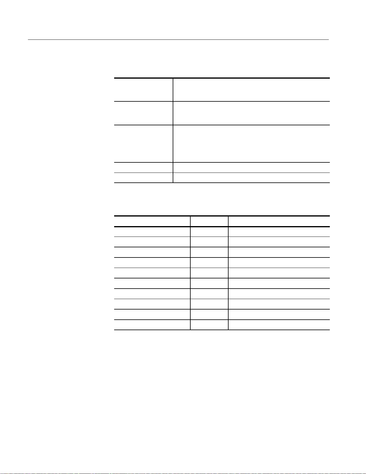
EC Declaration of Conformity
We
Tektronix Holland N.V.
Marktweg 73A
8444 AB Heerenveen
The Netherlands
declare under sole responsibility that the
A6906S Fiber Optic Isolation System
meets the intent of Directive 89/336/EEC for Electromagnetic Compatibility.
Compliance was demonstrated to the following specifications as listed in the Official
Journal of the European Communities:
EN 55011 Class A Radiated and Conducted Emissions
EN 50081-1 Emissions:
EN 60555-2 AC Power Line Harmonic Emissions
EN 50082-1 Immunity:
IEC 801-2 Electrostatic Discharge Immunity
IEC 801-3 RF Electromagnetic Field Immunity
IEC 801-4 Electrical Fast Transient/Burst Immunity
Page 6

Page 7

Table of Contents
List of Figures iii. . . . . . . . . . . . . . . . . . . . . . . . . . . . . . . . . . . . . . . . . . . . .
List of Tables iv. . . . . . . . . . . . . . . . . . . . . . . . . . . . . . . . . . . . . . . . . . . . . .
General Safety Summary v. . . . . . . . . . . . . . . . . . . . . . . . . . . . . . . . . . . .
Injury Precautions v. . . . . . . . . . . . . . . . . . . . . . . . . . . . . . . . . . . . . . . . . . . . . . . .
Product Damage Precautions vi. . . . . . . . . . . . . . . . . . . . . . . . . . . . . . . . . . . . . . . .
Safety Terms and Symbols vi. . . . . . . . . . . . . . . . . . . . . . . . . . . . . . . . . . . . . . . . . .
Preface vii. . . . . . . . . . . . . . . . . . . . . . . . . . . . . . . . . . . . . . . . . . . . . . . . . . .
Options viii. . . . . . . . . . . . . . . . . . . . . . . . . . . . . . . . . . . . . . . . . . . . . . . . . . . . . . . . .
Standard Accessories ix. . . . . . . . . . . . . . . . . . . . . . . . . . . . . . . . . . . . . . . . . . . . . .
Optional Accessories ix. . . . . . . . . . . . . . . . . . . . . . . . . . . . . . . . . . . . . . . . . . . . . .
Customer Support x. . . . . . . . . . . . . . . . . . . . . . . . . . . . . . . . . . . . . . . . . . . . . . . . .
Getting Started 1. . . . . . . . . . . . . . . . . . . . . . . . . . . . . . . . . . . . . . . . . . . .
AC Power 1. . . . . . . . . . . . . . . . . . . . . . . . . . . . . . . . . . . . . . . . . . . . . . . . . . . . . . .
Charging the Battery Pack 1. . . . . . . . . . . . . . . . . . . . . . . . . . . . . . . . . . . . . . . . . .
Preparing for Operation 3. . . . . . . . . . . . . . . . . . . . . . . . . . . . . . . . . . . . . . . . . . . .
Operating Basics 7. . . . . . . . . . . . . . . . . . . . . . . . . . . . . . . . . . . . . . . . . . .
Power On and Calibration 7. . . . . . . . . . . . . . . . . . . . . . . . . . . . . . . . . . . . . . . . . .
Optional T emperature Calibration 8. . . . . . . . . . . . . . . . . . . . . . . . . . . . . . . . . . . .
Operation 8. . . . . . . . . . . . . . . . . . . . . . . . . . . . . . . . . . . . . . . . . . . . . . . . . . . . . . .
Cleaning Fiber-Optic Cable Connectors 11. . . . . . . . . . . . . . . . . . . . . . . .
Programming 13. . . . . . . . . . . . . . . . . . . . . . . . . . . . . . . . . . . . . . . . . . . . . .
Setting Up 13. . . . . . . . . . . . . . . . . . . . . . . . . . . . . . . . . . . . . . . . . . . . . . . . . . . . . . .
GPIB Requirements 14. . . . . . . . . . . . . . . . . . . . . . . . . . . . . . . . . . . . . . . . . . . . . . .
Setting GPIB Parameters 14. . . . . . . . . . . . . . . . . . . . . . . . . . . . . . . . . . . . . . . . . . .
Other Documents You Will Need 15. . . . . . . . . . . . . . . . . . . . . . . . . . . . . . . . . . . . .
Commands 15. . . . . . . . . . . . . . . . . . . . . . . . . . . . . . . . . . . . . . . . . . . . . . . . . . . . . .
CALibration 16. . . . . . . . . . . . . . . . . . . . . . . . . . . . . . . . . . . . . . . . . . . . . . . . . . . . .
COUpling 17. . . . . . . . . . . . . . . . . . . . . . . . . . . . . . . . . . . . . . . . . . . . . . . . . . . . . . .
EVEnt? (Query Only) 17. . . . . . . . . . . . . . . . . . . . . . . . . . . . . . . . . . . . . . . . . . . . .
HELp? (Query Only) 17. . . . . . . . . . . . . . . . . . . . . . . . . . . . . . . . . . . . . . . . . . . . . .
ID? (Query Only) 18. . . . . . . . . . . . . . . . . . . . . . . . . . . . . . . . . . . . . . . . . . . . . . . . .
INIt (No Query Form) 18. . . . . . . . . . . . . . . . . . . . . . . . . . . . . . . . . . . . . . . . . . . . .
PRObe? (Query Only) 18. . . . . . . . . . . . . . . . . . . . . . . . . . . . . . . . . . . . . . . . . . . . .
RANge 19. . . . . . . . . . . . . . . . . . . . . . . . . . . . . . . . . . . . . . . . . . . . . . . . . . . . . . . . .
RQS 19. . . . . . . . . . . . . . . . . . . . . . . . . . . . . . . . . . . . . . . . . . . . . . . . . . . . . . . . . . .
SET? (Query Only) 20. . . . . . . . . . . . . . . . . . . . . . . . . . . . . . . . . . . . . . . . . . . . . . .
STAndby 20. . . . . . . . . . . . . . . . . . . . . . . . . . . . . . . . . . . . . . . . . . . . . . . . . . . . . . .
TRAns? (Query Only) 21. . . . . . . . . . . . . . . . . . . . . . . . . . . . . . . . . . . . . . . . . . . . .
TESt? (Query Only) 21. . . . . . . . . . . . . . . . . . . . . . . . . . . . . . . . . . . . . . . . . . . . . . .
Status Bytes and Event Codes 22. . . . . . . . . . . . . . . . . . . . . . . . . . . . . . . . . . . . . . .
A6906S Fiber-Optic Isolation System User Manual
i
Page 8

Table of Contents
Appendix A: Specifications 23. . . . . . . . . . . . . . . . . . . . . . . . . . . . . . . . . . .
Appendix B: Performance Verification 27. . . . . . . . . . . . . . . . . . . . . . . . .
Prerequisites 27. . . . . . . . . . . . . . . . . . . . . . . . . . . . . . . . . . . . . . . . . . . . . . . . . . . . .
Required T est Equipment 28. . . . . . . . . . . . . . . . . . . . . . . . . . . . . . . . . . . . . . . . . . .
Offset and Noise Check 28. . . . . . . . . . . . . . . . . . . . . . . . . . . . . . . . . . . . . . . . . . . .
Rise Time Check 29. . . . . . . . . . . . . . . . . . . . . . . . . . . . . . . . . . . . . . . . . . . . . . . . .
Bandwidth Check 31. . . . . . . . . . . . . . . . . . . . . . . . . . . . . . . . . . . . . . . . . . . . . . . . .
Gain Check 32. . . . . . . . . . . . . . . . . . . . . . . . . . . . . . . . . . . . . . . . . . . . . . . . . . . . . .
Probe Check 34. . . . . . . . . . . . . . . . . . . . . . . . . . . . . . . . . . . . . . . . . . . . . . . . . . . . .
Appendix C: GPIB Interface Messages 37. . . . . . . . . . . . . . . . . . . . . . . . .
Appendix D: Maintenance 41. . . . . . . . . . . . . . . . . . . . . . . . . . . . . . . . . . .
Replacing Fuses 42. . . . . . . . . . . . . . . . . . . . . . . . . . . . . . . . . . . . . . . . . . . . . . . . . .
Replacing the Probe 42. . . . . . . . . . . . . . . . . . . . . . . . . . . . . . . . . . . . . . . . . . . . . . .
Probe Compensation 45. . . . . . . . . . . . . . . . . . . . . . . . . . . . . . . . . . . . . . . . . . . . . .
Replacing the Fiber-Optic Cable 46. . . . . . . . . . . . . . . . . . . . . . . . . . . . . . . . . . . . .
Transmitter Panel Removal 47. . . . . . . . . . . . . . . . . . . . . . . . . . . . . . . . . . . . . .
Fiber-optic Cable Removal 48. . . . . . . . . . . . . . . . . . . . . . . . . . . . . . . . . . . . . .
Fiber-optic Cable Installation 49. . . . . . . . . . . . . . . . . . . . . . . . . . . . . . . . . . . .
Panel Installation 52. . . . . . . . . . . . . . . . . . . . . . . . . . . . . . . . . . . . . . . . . . . . . .
Calibration 52. . . . . . . . . . . . . . . . . . . . . . . . . . . . . . . . . . . . . . . . . . . . . . . . . . .
Appendix E: Replaceable Parts List 53. . . . . . . . . . . . . . . . . . . . . . . . . . .
Parts Ordering Information 53. . . . . . . . . . . . . . . . . . . . . . . . . . . . . . . . . . . . . . . . .
Using the Replaceable Parts List 53. . . . . . . . . . . . . . . . . . . . . . . . . . . . . . . . . . . . .
Glossary 59. . . . . . . . . . . . . . . . . . . . . . . . . . . . . . . . . . . . . . . . . . . . . . . . . .
Index 61. . . . . . . . . . . . . . . . . . . . . . . . . . . . . . . . . . . . . . . . . . . . . . . . . . . . .
ii
A6906S Fiber-Optic Isolation System User Manual
Page 9

List of Figures
Table of Contents
Figure i: Power-Cord Plug Options viii. . . . . . . . . . . . . . . . . . . . . . . . . . . .
Figure 1: A69T06 Battery Removal 2. . . . . . . . . . . . . . . . . . . . . . . . . . . .
Figure 2: Battery Charging 2. . . . . . . . . . . . . . . . . . . . . . . . . . . . . . . . . .
Figure 3: A6906S Connections for Use 3. . . . . . . . . . . . . . . . . . . . . . . . .
Figure 4: Connection of the Fiber-Optic Cable and Connector 4. . . . .
Figure 5: A69R06 Receiver Controls 9. . . . . . . . . . . . . . . . . . . . . . . . . . .
Figure 6: 6-Inch Ground Lead Clip 10. . . . . . . . . . . . . . . . . . . . . . . . . . . .
Figure 7: Fiber-Optic Cable and Connector Cleaning 11. . . . . . . . . . . .
Figure 8: Stacked GPIB Connectors 13. . . . . . . . . . . . . . . . . . . . . . . . . . .
Figure 9: Typical GPIB Network Configuration 14. . . . . . . . . . . . . . . . .
Figure 10: Noise Check Setup 29. . . . . . . . . . . . . . . . . . . . . . . . . . . . . . . .
Figure 11: Rise Time Check Setup 30. . . . . . . . . . . . . . . . . . . . . . . . . . . . .
Figure 12: Bandwidth Check Setup 31. . . . . . . . . . . . . . . . . . . . . . . . . . . .
Figure 13: Gain Check Setup 32. . . . . . . . . . . . . . . . . . . . . . . . . . . . . . . . .
Figure 14: Probe Check Setup 34. . . . . . . . . . . . . . . . . . . . . . . . . . . . . . . .
Figure 15: Replacing the probe 43. . . . . . . . . . . . . . . . . . . . . . . . . . . . . . .
Figure 16: Removing the Panel 48. . . . . . . . . . . . . . . . . . . . . . . . . . . . . . .
Figure 17: Fiber-optic Cable Installation (for Type A) 49. . . . . . . . . . . .
Figure 18: Connection of the Fiber-optic Cable and Connector 50. . . . .
Figure 19: Fiber-optic Cable Installation (for Type B) 51. . . . . . . . . . . .
Figure 20: Replaceable Parts 56. . . . . . . . . . . . . . . . . . . . . . . . . . . . . . . . .
Figure 21: Accessories 57. . . . . . . . . . . . . . . . . . . . . . . . . . . . . . . . . . . . . . .
A6906S Fiber-Optic Isolation System User Manual
iii
Page 10

Table of Contents
List of Tables
Table i: A6906S Order Options viii. . . . . . . . . . . . . . . . . . . . . . . . . . . . . .
Table 1: A6906S Attenuation Factors with Probe Factor Included 9. .
Table 2: A6906S GPIB Commands 16. . . . . . . . . . . . . . . . . . . . . . . . . . . .
Table 3: Status Bytes 22. . . . . . . . . . . . . . . . . . . . . . . . . . . . . . . . . . . . . . .
Table 4: Event Codes 22. . . . . . . . . . . . . . . . . . . . . . . . . . . . . . . . . . . . . . .
Table 5: Electrical Specifications 23. . . . . . . . . . . . . . . . . . . . . . . . . . . . .
Table 6: Fiber-Optic Cable Characteristics 25. . . . . . . . . . . . . . . . . . . . .
Table 7: Battery Characteristics 25. . . . . . . . . . . . . . . . . . . . . . . . . . . . . .
Table 8: Physical Characteristics 25. . . . . . . . . . . . . . . . . . . . . . . . . . . . .
Table 10: GPIB Interface Functions 26. . . . . . . . . . . . . . . . . . . . . . . . . . .
Table 11: Test Equipment Required for Performance Verification 28. .
Table 12: Gain Accuracy Limits 33. . . . . . . . . . . . . . . . . . . . . . . . . . . . . .
Table 13: Available Fiber-Optic Cables 46. . . . . . . . . . . . . . . . . . . . . . . .
Table 14: Fiber-Optic Cable Changes Requiring Recalibration 46. . . .
iv
A6906S Fiber-Optic Isolation System User Manual
Page 11

General Safety Summary
Review the following safety precautions to avoid injury and prevent damage to
this product or any products connected to it.
Injury Precautions
Use Proper Power Cord
Avoid Electric Overload
Do Not Operate Without
Covers
Do Not Operate in
Wet/Damp Conditions
Ground the Product
Use Proper Fuse
Do Not Operate in
Explosive Atmospheres
To avoid fire hazard, use only the power cord specified for this product.
To avoid electric shock or fire hazard, do not apply a voltage to a probe that is
outside the range specified for that probe.
To avoid electric shock or fire hazard, do not operate this product with covers or
panels removed.
To avoid electric shock, do not operate this product in wet or damp conditions.
Portions of this product are grounded through the grounding conductors of the
power cords. To avoid electric shock, the grounding conductor must be
connected to earth ground. Before making connections to the input or output
terminals of the product, ensure that the product is properly grounded.
To avoid fire hazard, use only the fuse types and ratings specified for this
product.
To avoid injury or fire hazard, do not operate this product in an explosive
atmosphere.
Wear Eye Protection
A6906S Fiber-Optic Isolation System User Manual
Wear eye protection if exposure to high-intensity rays or laser radiation exists.
v
Page 12

General Safety Summary
Product Damage Precautions
Use Proper Power Source
Do not operate this product from a power source that applies more than the
voltage specified.
Do Not Operate With
Suspected Failures
If you suspect there is damage to this product, have it inspected by qualified
service personnel.
Safety Terms and Symbols
Terms in This Manual
Terms on the Product
These terms may appear in this manual:
WARNING statements identify conditions or practices that could result in injury
or loss of life.
CAUTION statements identify conditions or practices that could result in
damage to this product or other property.
These terms may appear on the product:
DANGER indicates an injury hazard immediately accessible as you read the
marking.
Symbols in This Manual
Symbols on the Product
vi
WARNING indicates an injury hazard not immediately accessible as you read the
marking.
CAUTION indicates a hazard to property including the product.
This symbol may appear in the manual:
This symbol indicates where specific cautions and warnings are found.
These symbols may appear on the product:
DANGER
High Voltage
Protective ground
(earth) terminal
ATTENTION
Refer to
manual
A6906S Fiber-Optic Isolation System User Manual
Page 13

Preface
The A6906S Fiber-Optic Isolation System allows long-distance transmission of
electrical signals. Features include:
H Ability to safely use the transmitter in a floating or ungrounded environment.
H Electrical isolation between transmitter and receiver.
H Up to 200 meter fiber-optic cable length (with Option 3).
H 100 MHz bandwidth.
The A6906S Fiber-Optic Isolation System converts an input analog electrical
signal into an optical signal. This signal is then transmitted along the fiber-optic
cable, received, and converted back into an electrical signal. This transmission
scheme provides a signal transmission system that operates over long distances,
offers low distortion, transmits at high speed, and electrically insulates the
signal. The A6906S Fiber-Optic Isolation System has the following components:
H A69T06 Transmitter, with battery pack, fiber-optic cable, and probe.
H A69R06 Receiver.
H A69C06 Sealed Lead-Acid Battery Charger.
The A69T06 Transmitter is an electrical-to-optical (E/O) converter; it converts
an input electrical signal into an optical signal. System gain is controlled by an
attenuator that is set in a 1–2–5 sequence. The A69T06 is also provided with a
variable-gain amplifier for self-calibration to maintain measurement precision.
The A69T06 is powered by an internal sealed rechargeable lead-acid battery
pack.
The A69R06 Receiver is an optical-to-electrical (O/E) converter. It converts an
optical signal input, via a fiber-optic cable, into an electrical signal. This unit
functions as the controller for the A69T06 Transmitter. It can be used to control
self-calibration and transmitter attenuator switching using front-panel operations.
The A69R06 can also be controlled from an external device via the GPIB
(IEEE–488) interface.
The A69C06 Sealed Lead-Acid Battery Charger charges the battery pack while
the battery pack is removed from the A69T06.
A6906S Fiber-Optic Isolation System User Manual
vii
Page 14
Preface
Options
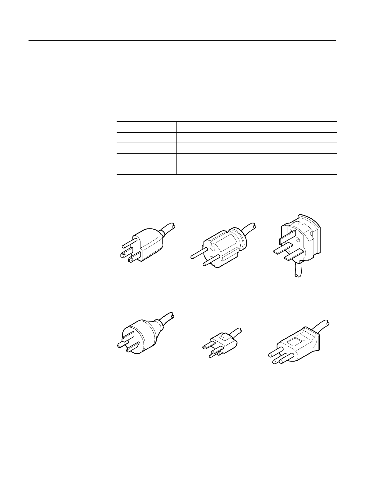
You can order the A6906S Fiber-Optic Isolation System with different options,
as listed in Tables i and Figure i.
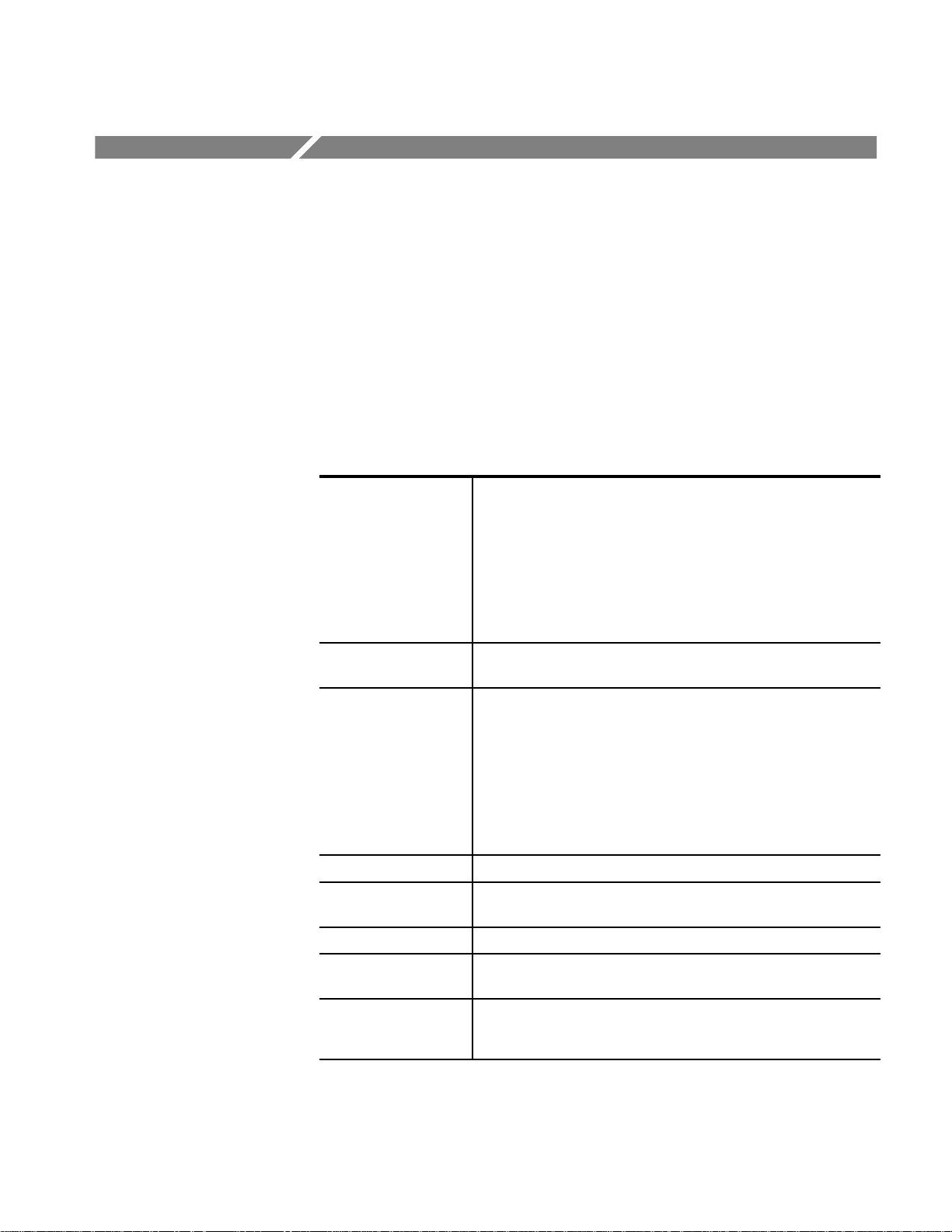
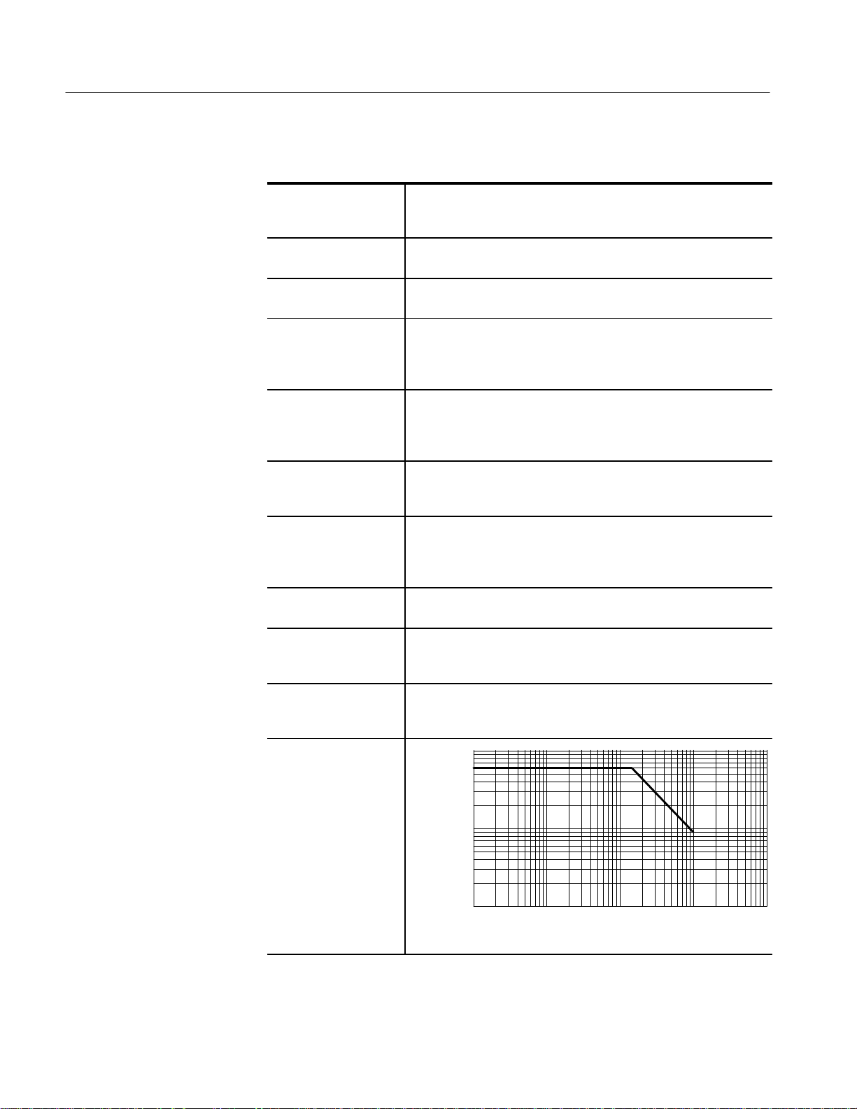
T able i: A6906S Order Options
Option Number Description
01 Replace standard 3 meter fiber-optic cable with 20meter cable.
02 Replace standard 3 meter fiber-optic cable with 100 meter cable.
03 Replace standard 3 meter fiber-optic cable with 200 meter cable.
04 Replace standard 3 meter fiber-optic cable with 10 meter cable.
Standard*
North American
115V
Option A3
Australian
230V
* Canadian Standards Association certification
includes these power plugs for use in the
North American power network
Option A1
Universal Euro
Option A4*
North American
Figure i: Power-Cord Plug Options
230V
230V
Option A2
UK
230V
Option A5
Switzerland
230V
viii
A6906S Fiber-Optic Isolation System User Manual
Page 15

Standard Accessories
Preface
The standard accessories that are included with the A6906S are listed below.
Accessories, for example spare battery packs, can be ordered separately by using
the Tektronix part numbers listed in the Replaceable Parts List on page 53.
H battery pack
H 50 W BNC Cable
H 50 W Feedthrough Termination
H Industrial lead set (for banana plug test accessories)
H Retractable Hook Probe Tip
H Spare Fuse for the A69R06
H Spare Fuse for the A69C06
H Fiber-Optic Cable Connector Cleaner (set of 5)
Optional Accessories
H A6906S Fiber-Optic Isolation System User Manual
H Two power cords
H 6-Inch Ground Lead
The optional accessories listed below can be ordered for use with your A6906S.
Tektronix part numbers for these accessories can be found in the Replaceable
Parts List on page 53.
H 75 W BNC Cable
H 75 W Feedthrough Termination
H GPIB Cable
H Index Matching Oil (for optical cable connections)
H Fiber-Optic Cable Connector Cleaner (set of 200)
A6906S Fiber-Optic Isolation System User Manual
ix
Page 16

Preface
Customer Support
To help you get the best performance from your A6906S, Tektronix offers the
sales, application, and service support:
Sales Support
Application Support
Service Support
To order optional equipment and accessories, call the Tektronix National
Marketing Center at 1-800-426-2200. Outside the United States or Canada,
contact your nearest Tektronix Service Center.
For assistance in applying the A6906S Fiber-Optic Isolation System to your
measurement needs, contact Tektronix Customer Support at 1-800-835-9433
x2400, between 6 am and 5 pm Pacific time. Outside the United States or
Canada, contact your nearest Tektronix Service Center.
To obtain exchange modules to repair your A6906S, call the Tektronix FastParts
Center at 1-800-848-5083. If you want Tektronix to perform repair or calibration
services, or should your A6906S system need repair beyond that described in
this manual, contact your nearest Tektronix Service Center.
x
A6906S Fiber-Optic Isolation System User Manual
Page 17

Getting Started
This section tells you how to set up the A6906S Fiber-Optic Isolation System for
battery charging and normal operation. Since the A69T06 Transmitter operates
using battery power, you will first need to charge the battery pack.
AC Power
The A6906S Fiber-Optic Isolation System is capable of continuous operation
with input voltages that range from 90 V to 250 V with source voltage frequencies from 47 Hz to 66 Hz.
Detachable three-wire power cords with three-contact plugs are provided with
the A69R06 Receiver and A69C06 Sealed Lead-Acid Battery Charger for
connection to both the power source and protective ground. For electrical shock
protection, insert these plugs into a power source outlet that has a properly
grounded protective ground contact.
Charging the battery pack
The A69T06 Transmitter is powered from a battery pack. To charge the battery
pack, you need to remove it from the A69T06 Transmitter. It takes 12 hours to
charge a battery pack that has been fully discharged. You cannot use a battery
pack to power the A6906S while the battery pack is charging, but you can use a
second battery pack to operate the A69T06 while charging a battery pack using
the A69C06.
WARNING. Before removing the battery pack for charging, disconnect the probe
from the circuit being measured.
Do not put your hand or any foreign object into the battery pack compartment
after removing the battery pack.
Do not use the A69C06 Sealed Lead-Acid Battery Charger with any instrument
or battery other than the A6906S battery pack.
1. Connect the A69C06 Sealed Lead-Acid Battery Charger to the AC power
source through the supplied grounded power cord. Make sure that the green
POWER light is on.
2. Turn off the A69T06 by pressing the OFF button on the battery pack. The
red power light will turn off.
A6906S Fiber-Optic Isolation System User Manual
1
Page 18
Getting Started
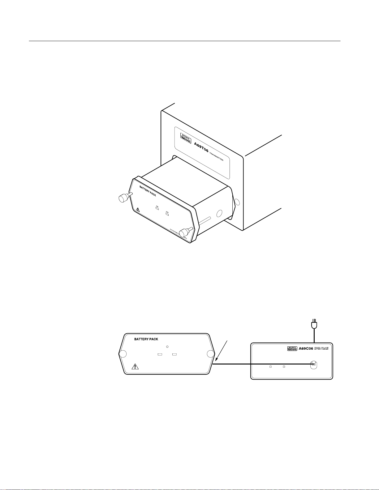
3. Remove the battery pack from the A69T06 by unscrewing the two thumb-
screws on the front of the battery pack, as shown in Figure 1. Pull the battery
pack completely out of the A69T06.
Figure 1: A69T06 Battery Removal
4. Connect the cable from the A69C06 OUTPUT to the connector on the right
side of the battery pack, as shown in Figure 2.
To AC Power
Source
Side Connector
OUTPUT
Figure 2: Battery Charging
5. Make sure the red CHARGE light on the front of the A69C06 is on. When
the battery pack is fully charged, this light will turn off.
2
A6906S Fiber-Optic Isolation System User Manual
Page 19
Preparing for Operation
Getting Started
NOTE. battery packs are shipped fully charged. If you do not see the charge light
come on, the battery pack is still fully charged and can be used immediately.
6. When the battery pack is fully charged, disconnect it from the A69C06 and
reinstall it in the A69T06 Transmitter. Install the battery pack right-side up
in the A69T06, or the A69T06 will not operate even though the power light
turns on.
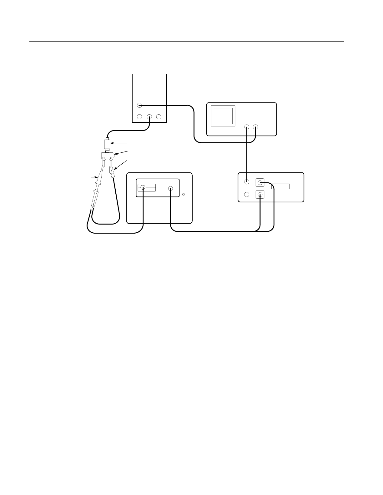
Figure 3 shows the connections necessary to use the A6906S Fiber-Optic
Isolation System.
NOTE. The A69T06 Transmitter, fiber-optic cable, and A69R06 Receiver have
been calibrated at the factory as a unit. Do not exchange modules among
A6906S Fiber-Optic Isolation Systems; Tektronix will not warrant performance
to specifications if you do so. Always use an A69T06 and A69R06 having
matching serial numbers.
Test Oscilloscope
50 W oscilloscope
input (or add 50 W
termination here if
oscilloscope has only
high-impedance input).
50 W Output
White
75 W Output
Red
Figure 3: A6906S Connections for Use
Connecting the
Fiber-Optic Cable
The fiber-optic cable connects the A69R06 Receiver to the A69T06 Transmitter.
The cable consists of two optical conductors, one for signal and one for control
commands. The two optical conductors are marked with different colored
protective caps: white marks the signal conductor and red marks the command
conductor.
A69R06
SIGNAL
COMMAND
To AC Power
Source
Fiber-Optic Cable
A69T06
Probe
A6906S Fiber-Optic Isolation System User Manual
3
Page 20
Getting Started
CAUTION. Be careful not to bend the fiber-optic cable excessively or apply
excessive force. When storing the fiber-optic cable, be sure to replace the cable
and the unit’s protective caps to protect them from soiling.
1. Remove the protective caps from the A69R06 SIGNAL and COMMAND
connectors.
2. Remove the red protective cap from the fiber-optic cable.
3. Remove the clear plastic protector from the optical surface of the fiber-optic
cable.
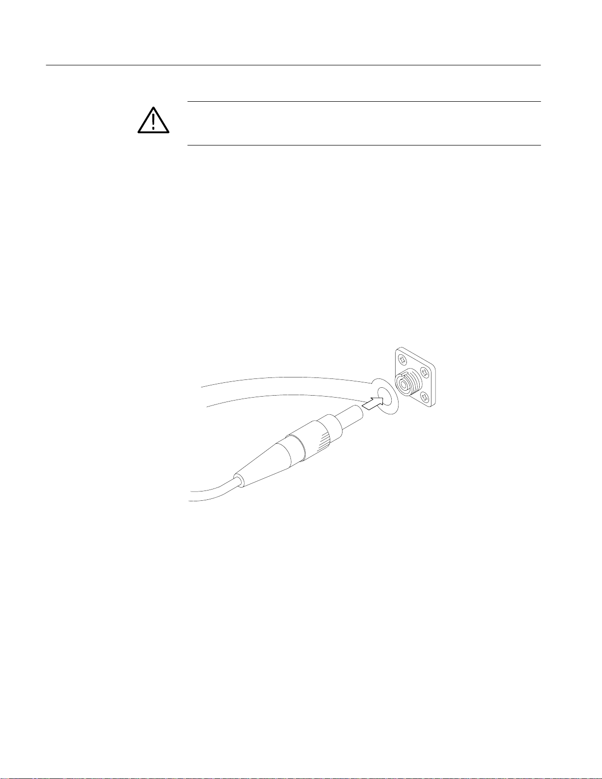
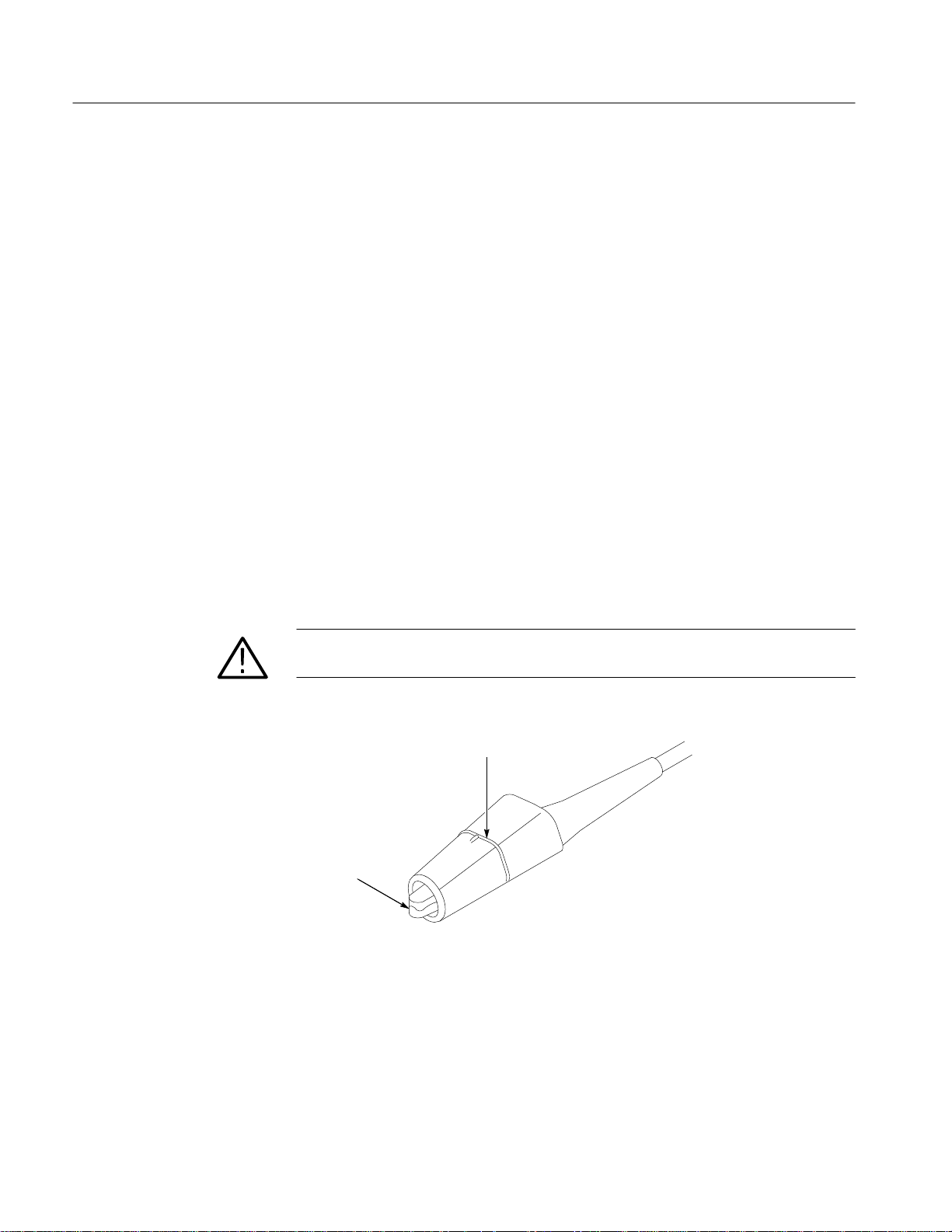
4. Place the cable strain relief around the A69R06 COMMAND conductor as
shown in Figure 4.
5. Insert the uncovered cable plug into the A69R06 COMMAND conductor.
Verify that the plug’s notch is completely seated in the connector’s groove
and then tighten the plug retaining ring, hand tight only.
Connecting to the
Oscilloscope
Strain relief on one connector only
Figure 4: Connection of the Fiber-Optic Cable and Connector
6. Repeat steps 2 and 5 for the white-capped fiber-optic cable, connecting it to
the A69R06 SIGNAL connector.
Use the included 50 W BNC cable to connect the A69R06 50 W OUTPUT to a
50 W oscilloscope input. If you have a 75 W system, you can use the 75 W
OUTPUT connector instead.
If your oscilloscope has only high-impedance inputs, you can install the included
50 W feedthrough termination between the oscilloscope input and the 50 W BNC
cable. Do not install the termination at the A69R06 end of the cable.
4
A6906S Fiber-Optic Isolation System User Manual
Page 21

Getting Started
NOTE. The self-calibration feature of the A6906S requires that the 50 W output of
the A69R06 be terminated into 50 W. If you are using a 75 W system, attach the
50 W feedthrough termination to the 50 W output and use the 75 W output to
connect to the system input.
AC Power
Connect the A69R06 Receiver to the AC power source through the supplied
grounded power cord.
Once you have connected the fiber-optic cable, the oscilloscope, and the power
cord, the A6906S Fiber-Optic Isolation System system is ready to power on and
use.
A6906S Fiber-Optic Isolation System User Manual
5
Page 22

Getting Started
6
A6906S Fiber-Optic Isolation System User Manual
Page 23

Operating Basics
This section tells you how to operate the A6906S Fiber-Optic Isolation System
once it is installed.
NOTE. To use this section, you must first install the A6906S as described in the
Getting Started section starting on page 1. A battery pack must be charged and
installed in the A69T06 Transmitter.
Power On and Calibration
The A6906S requires that both the A69T06 Transmitter and A69R06 Receiver be
powered on. The A69T06 takes power from its battery pack, and the A69R06
takes power from the AC line.
1. On the A69T06 battery pack, press the ON button to turn on transmitter
2. On the A69R06, turn on the power using the POWER OFF/ON switch on
power. The red light between the ON and OFF buttons will turn on.
the back panel.
If the attenuation display shows Er1, check the fiber-optic cable connections
between the transmitter and receiver. If necessary, clean the optical connectors as described in Cleaning Optical Connectors on page 11.
Allow the system to warm up for 20 minutes before proceeding. If you do
proceed to use the A6906S, perform step 3 below after 20 minutes have
passed since power on. Performance to specifications is guaranteed only after
20 minutes warm-up.
NOTE. The self-calibration feature of the A6906S requires that the 50 W output of
the A69R06 be terminated into 50 W. If you are using a 75 W system, attach the
50 W feedthrough termination to the 50 W output and use the 75 W output to
connect to the system input.
3. On the A69R06 front panel, press the CAL button to initiate the calibration
procedure. The transmitter and receiver will calibrate themselves to each
other. The calibration process takes approximately one minute the first time
after power on, subsequent calibrations take approximately 30 seconds.
When the calibration is complete, the green PASS light will turn on.
A6906S Fiber-Optic Isolation System User Manual
7
Page 24

Operating Basics
If the red FAIL light comes on instead, check the fiber-optic cable connections between the transmitter and receiver. If necessary, clean the optical
connectors as described in Cleaning Optical Connectors on page 11. If the
green PASS light still doesn’t come on, the instrument needs repair.
Once the A6906S is powered up and calibrated, it is controlled by the front panel
buttons on the front of the A69R06 Receiver. It can also be controlled by a GPIB
computer or controller connected to the A69R06, making it a part of an
automated test system.
Optional Temperature Calibration
The A69T06 monitors its internal temperature and applies internal calibration
corrections to compensate for drift in offset. Temperature does not affect the
A69R06 and so it has no temperature monitoring system.
Normally, temperature corrections are applied based on default correction values.
You can override the default values with values that are optimized to a specific
temperature; however, if the temperature changes while the override values are in
effect the A69T06 will not correct the for the offset drift induced by the changed
temperature. To set optimum override values, follow these steps:
Operation
1. Install the A6906S in the environment in which it will be used.
2. On the A69R06, press the CAL and COUPLING buttons simultaneously.
3. Press the A69R06 COUPLING button again.
4. Allow the temperature environment to stabilize. Do not continue to step 5
until the A69T06 has been in a temperature-stable environment for at least
20 minutes.
5. Press the A69R06 COUPLING button again. Until this step is completed,
the A6906S will not respond to GPIB commands.
To return to normal operation with default temperature correction values:
1. Install the A6906S in the environment in which it will be used.
2. On the A69R06, press the CAL and COUPLING buttons simultaneously.
3. Press the A69R06 CAL button again.
To use the A6906S Fiber-Optic Isolation System to take a measurement, connect
the probe to the circuit you want to test, select the ATTENUATOR and
COUPLING settings on the A69R06, and view the output on the oscilloscope.
8
A6906S Fiber-Optic Isolation System User Manual
Page 25
Operating Basics
WARNING. Do not apply the probe to voltages that exceed the maximum ratings
indicated on the rear panel of the A69T06.
"
W
"
W
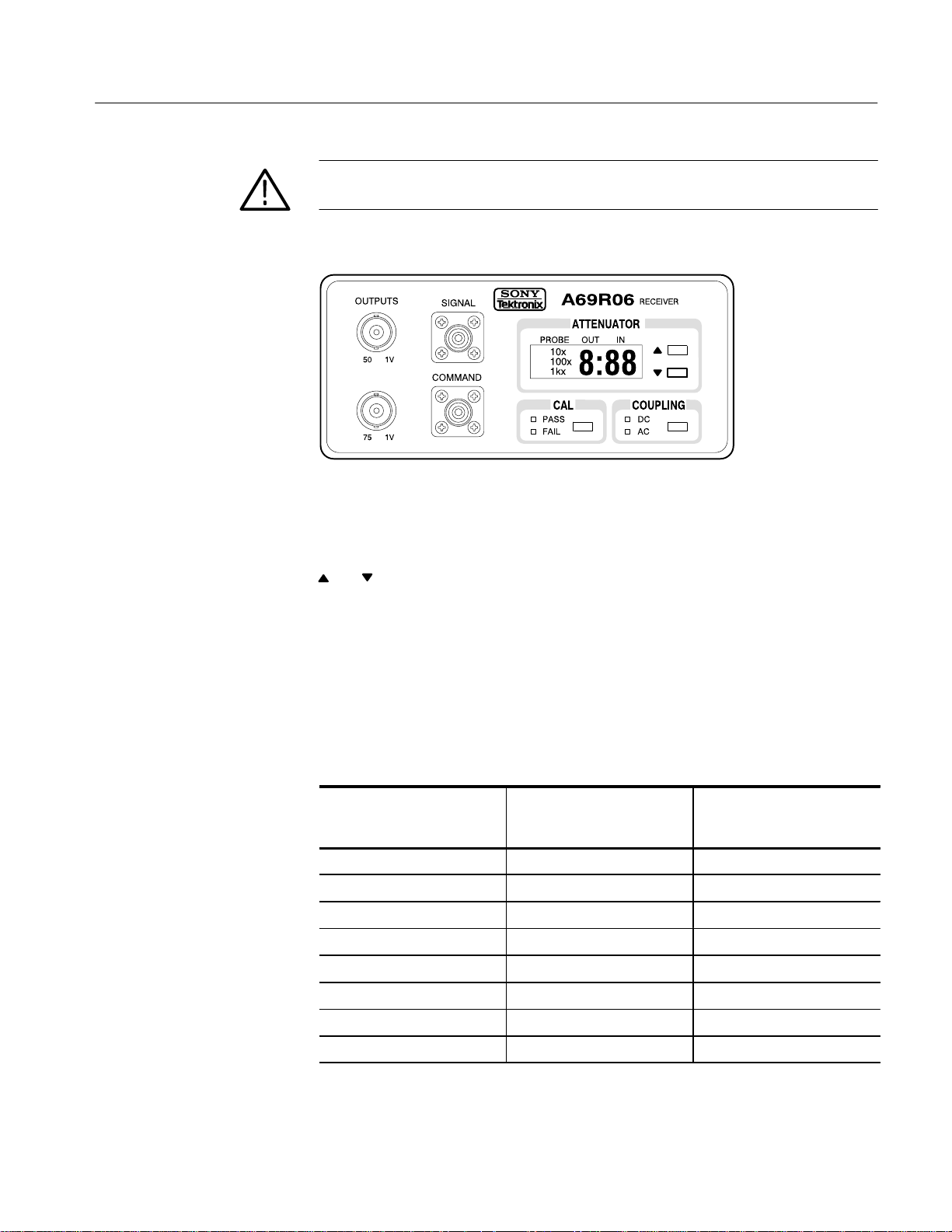
Figure 5: A69R06 Receiver Controls
Attenuator Controls
The ATTENUATOR controls consist of a digital readout and two buttons,
and . The digital readout displays the attenuation factor of the A69T06 and
A6906S, but does not include the 100× attenuation of the probe. The 100× light
in the attenuator display is always on to remind you to include this factor when
reading the displayed attenuation.
The buttons adjust the attenuation factor up or down, to increase or decrease the
displayed height of the signal on the oscilloscope display. Table 1 shows the
attenuation factors of the A69T06 including probe.
T able 1: A6906S Attenuation Factors with Probe Factor Included
Probe Tip to
Displayed Attenuation
Factor
Oscilloscope Input
Attenuation
1:50 5,000× 8mV
1:20 2,000× 20 mV
1:10 1,000× 40 mV
1:5 500× 80 mV
1:2 200× 200 mV
1:1 100× 400 mV
2:1 50× 800 mV
5:1 20× 2.0 V
Output Amplitude of a
40 V
Signal
p-p
p-p
p-p
p-p
p-p
p-p
p-p
p-p
p-p
A6906S Fiber-Optic Isolation System User Manual
9
Page 26
Operating Basics
Calibration Controls
Coupling Controls
Oscilloscope Controls
6-Inch Ground Lead
The CAL button starts the self-calibration process . This performs automatic
internal adjustments in the A69T06 and A69R06, and adjusts the transmitter and
receiver to each other. When the calibration is complete, the green PASS and red
FAIL lights tell you whether the self-calibration was successful.
If the self-calibration fails, clean the optical connectors as described in Cleaning
Fiber-Optic Cable Connectors on page 11. If the green PASS light still doesn’t
come on, the instrument needs repair.
The COUPLING button changes the A6906S system to either DC or AC
coupling. Push the button to change the setting from one to the other. The green
DC or AC lights tell you which coupling mode is selected.
The oscilloscope you use with the A6906S provides controls for triggering,
horizontal size, vertical size, and other display parameters. Use these oscilloscope controls just as you would when using a regular oscilloscope probe.
Figure 6 shows the 6-inch ground lead that is included with the A6906S as a
standard accessory. Use the 6-inch ground lead in place of the longer ground lead
for measuring fast-rising waveforms.
WARNING. To avoid electrical shock, do not touch the metal of the ground clip.
Handle the clip by the insulation above the Limit Mark as shown in Figure 6.
Limit Mark
Metal Part
Figure 6: 6-Inch Ground Lead Clip
10
A6906S Fiber-Optic Isolation System User Manual
Page 27

Cleaning Fiber-Optic Cable Connectors
If the fiber-optic cable or front panel optical connector is dirty, the system may
not perform as it should or may fail self-calibration. If the fiber-optic cable or
connector is dirty, use the fiber-optic cleaner accessory to clean it as shown in
Figure 7. Normally, a single cleaner can clean a number of fiber-optic cables or
connectors. If the connector is extremely dirty, use a small amount of alcohol and
use the cleaner only once.
Figure 7: Fiber-Optic Cable and Connector Cleaning
A6906S Fiber-Optic Isolation System User Manual
11
Page 28

Cleaning Optical Connectors
12
A6906S Fiber-Optic Isolation System User Manual
Page 29

Programming
Setting Up
You can use a computer to control the A6906S and make measurements. With an
oscilloscope that also can be programmed, the computer and A6906S can form a
complete, automated measurement system.
Your computer, also known as the controller, must be capable of operating on a
GPIB bus that conforms to IEEE Std 488.1–1987. GPIB cards are available to
provide this capability for personal computers.
The A69R06 Receiver has a 24-pin GPIB connector on its rear panel, as shown
in Figure 8. This connector has a D-type shell and conforms to IEEE Std
488.1–1987.
Attach an IEEE Std 488.1–1987 GPIB cable between this connector and your
controller. Figure 8 shows how cables can be stacked together. You can stack a
second cable on either the receiver connector or the controller connector, to
similarly connect your oscilloscope.
Figure 8: Stacked GPIB Connectors
A6906S Fiber-Optic Isolation System User Manual
13
Page 30
Programming
GPIB Requirements
Observe these rules when you use your A69R06 with a GPIB network:
H Assign a unique device address to each device on the bus. No two devices
can share the same device address.
H Do not connect more than 15 devices to the bus.
H Connect one device for every 2 meters (6 feet) of cable used.
H Do not use more than 20 meters (65 feet) of cable for the entire bus.
H Power on at least two-thirds of the devices on the network while using the
network.
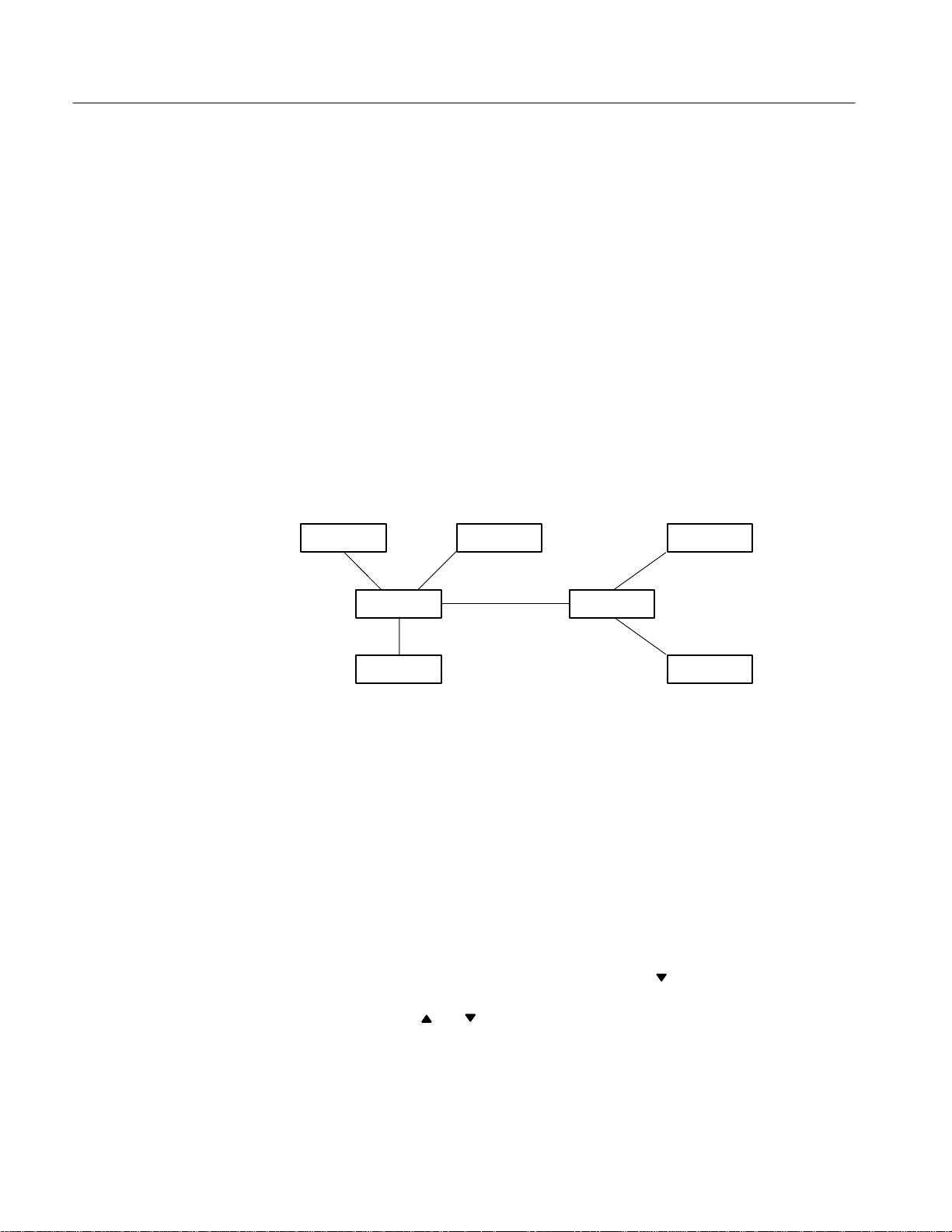
H Connect the devices on the network in a star or linear configuration as shown
in Figure 9. Do not use loop or parallel configurations.
Figure 9: Typical GPIB Network Configuration
Setting GPIB Parameters
You must set the GPIB parameters of the A69R06 to match the configuration of
the bus and controller.
GPIB Address
Set the GPIB ADDRESS using the A69R06 front panel. The GPIB controller
uses this address to send commands to the A69R06. The address of the A69R06
must be different from the addresses used by all other devices on the bus.
To set the GPIB address, press the ATTENUATOR
simultaneously and then release them. The attenuator display shows the current
address. Press the
address is set, press the COUPLING button to return to normal operation.
GPIB Device
GPIB Device
GPIB Device
GPIB Device
GPIB Device
GPIB Device
GPIB Device
and COUPLING buttons
and buttons to change the address. When the proper
14
A6906S Fiber-Optic Isolation System User Manual
Page 31

Programming
You can set the address from 0 through 30. You can also set the A69R06 to “off
line,” which disables all communications with the controller, by specifying
address 31.
GPIB Terminator
The termination mode specifies what conditions the A69R06 looks for to
determine the end of a command. The terminator may be set to “EOI” only or
“LF or EOI.” You will need to consult your controller documentation to
determine which setting is best for your configuration.
To set the GPIB terminator, press the ATTENUATOR
buttons simultaneously and then release them. The attenuator display shows the
current termination. Press the
the proper termination mode is set, press the COUPLING button to return to
normal operation.
The termination mode also specifies the termination of output messages from the
A69R06 to the controller. When the mode is “LF or EOI,” the A69R06 adds CR
and LF characters to the end of messages. In “EOI” only mode, the A69R06 adds
no characters to messages.
Other Documents You Will Need
Tektronix cannot know what type of controller you will use with your A69R06,
and so this document cannot cover the topics that are specific to your installation. To completely understand and implement a GPIB system, you will need the
documentation that supports your controller. If you are using a personal
computer with a GPIB card, you will need the documentation for both the PC
and the GPIB card.
and COUPLING
and buttons to change the termination. When
Commands
Command names show both upper- and lower-case characters. Only the
upper-case characters are required. You can abbreviate commands by omitting
lower-case characters, starting from the end. For example, you can enter the
COUpling command as COUPLING, COUPL, or COU. You can use lower-case
letters anyplace in command names or arguments: coUpLiNg, CouPl, or cou are
valid.
A6906S Fiber-Optic Isolation System User Manual
15
Page 32

Programming
T able 2: A6906S GPIB Commands
Command Name Description
CALibration Executes self-calibration, optionally returns result
COUpling Sets or queries input coupling
EVent? Returns the last pending event code
HELp? Returns a list of A6906S GPIB commands
ID? Returns instrument ID including firmware version numbers
INIt Initializes A6906S to factory default settings
PROBE? Returns the probe type
RANge Sets or queries the attenuator range
RQS Enables or disables system requests (SRQs)
SERIAL? Returns A6906S serial number
SET? Returns all A6906S settings as command string
ST Andby Sets or queries standby mode
CALibration
Syntax
Returns
Examples
TRAns? Queries status of transmitter
TESt? Performs A6906S self test query
Initiates the self-calibration of the A6906S. The query form returns the result.
PASS or FAIL, depending on the self-calibration result.
CALIBRATION
performs a self-calibration of the A6906S without a return message.
CAL?
might return CAL PASS.
16
A6906S Fiber-Optic Isolation System User Manual
Page 33

COUpling
Programming
Sets or queries the input coupling of the A6906S.
Syntax
Arguments
Examples
EVEnt? (Query Only)
Syntax
COUpling AC
COUpling DC
COUpling?
AC sets the input to AC coupling. DC sets the input to DC coupling.
COU DC
sets the A6906S input to DC coupling.
COU?
might return COUP DC, indicating that the A6906S input is set to DC coupling.
Returns the error or event code for the most recent event reported by serial poll,
or for the highest priority condition pending.
EVEnt?
Returns
Examples
HELp? (Query Only)
Syntax
Returns
The most recent error/event code.
EVE?
might return EVENT 266 as the most recent error code.
Returns a list of commands that are recognized by the A6906S.
HElp?
Will always return the string CAL, COU, EVE, HEL, ID, INI, PRO, RAN, RQS,
SET, STA, TRA, TES
A6906S Fiber-Optic Isolation System User Manual
17
Page 34

Programming
ID? (Query Only)
Returns the A6906S identification, including the Codes and Formats Version and
the firmware version.
Syntax
Returns
Examples
INIt (No Query Form)
Syntax
PRObe? (Query Only)
Syntax
ID?
The instrument identification string.
ID?
may return the string ID SONY_TEK/A69R06, V81.1, FV1.00
Initializes the A6906S (both A69R06 and A69T06) to factory default settings.
INIt
Returns the type of probe connected to the A69T06. This will always be X100.
PROBETYpe?
18
Returns
Examples
PROBETYPE X100
PROBETY?
will return PROBETYPE X100.
A6906S Fiber-Optic Isolation System User Manual
Page 35

RANge
Programming
Sets or queries the A6906S attenuator range setting.
Syntax
Arguments
Examples
RANge 1:50
RANge 1:20
RANge 1:10
RANge 1:5
RANge 1:2
RANge 1:1
RANge 2:1
RANge 5:1
RANge?
The argument tells how much the A6906S should attenuate or amplify the input
signal.
RAN 1:50
sets the A6906S to attenuate signals by a factor of 50. (Combined with the 100×
probe, the total attenuation is a factor of 5,000.)
RAN?
might return RANGE 1:1, indicating that the A6906S is set to neither amplify
nor attenuate.
RQS
Enables or disables SRQs (System Requests). When disabled, the A6906S does
not act on error conditions other than to log them, and does not signal that it is
ready to transmit data to the controller.
Syntax
Arguments
Examples
A6906S Fiber-Optic Isolation System User Manual
RQS ON
RQS OFF
RQS?
ON enables SRQ events. Off disables SRQ events.
RQS ON
enables SRQ events.
19
Page 36

Programming
SET? (Query Only)
Returns a string containing all the individual programming commands required
to return the A6906S to its present state. This string can be saved and sent at
some future time when you want to return the A6906S to all the present settings.
STAndby
Syntax
Returns
Examples
Syntax
Arguments
SET?
COU <AC | DC>;RAN <1:50 | 1:20 | 1:10 | 1:5 | 1:2 | 1:1 | 2:1 |
5:1>;RQS <ON | OFF>;STA <ON | OFF>
SET?
might return COU AC;RAN 1:2;RQS OFF;STA OFF
Enables or disables the standby mode, or queries the current standby mode
setting.
STAndby ON
STAndby OFF
STAndby?
ON turns standby mode on, OFF turns standby mode off.
20
Returns
Examples
ON or OFF
STA ON turns on standby mode.
STA?
might return STANDBY OFF, indicating standby mode is off.
A6906S Fiber-Optic Isolation System User Manual
Page 37

TRAns? (Query Only)
Programming
Queries the state of the A69T06. This is needed because the GPIB interface is a
part of the A69R06.
Syntax
Returns
Examples
TESt? (Query Only)
Syntax
Returns
NORMAL if the A69T06 has a charged battery and is responding normally,
LOW if the battery pack has a low charge level, OFF if it is powered off or not
responding, or UNKNOWN if the A69R06 cannot determine the status.
TRA?
might return TRA NORMAL, indicating that the A69T06 is operating normally
with a full battery charge.
Instructs the A6906S to perform a self-test operation and return the result.
PASS or FAIL
Examples
A6906S Fiber-Optic Isolation System User Manual
TES?
might return TEST PASS, indicating that the self-test completed successfully
with no errors.
21
Page 38

Programming
Status Bytes and Event Codes
The status and error reporting system of the A69R06 interrupts the controller by
asserting an SRQ (service request). The service request indicates that an event
has occurred that requires attention. When the controller polls the bus, the status
byte returned by the A69R06 indicates the type of event that occurred. A further
EVEnt? query will return an event code that gives more specific information
about the cause of the service request. The SRQ status byte and the event code
provide a limited amount of information about the specific cause of the service
request.
T able 3: Status Bytes
Category RQS Off RQS On RQS Off RQS On
No Status 0000 0000 0000 0000 0 0
Power On 0000 0001 0100 0001 1 65
Binary Decimal
Operation Complete 0000 0010 0100 0010 2 66
Command Error 0010 0001 0110 0001 33 97
Execution Error 0010 0010 0110 0010 34 98
Internal Error 0010 0011 01 10 0011 35 99
Execution Warning 0010 0110 0110 0110 38 102
T able 4: Event Codes
Category Code Description
Command Errors 101 Command header error
103 Command argument error
106 Missing argument
151 Command statement too long
Execution Errors 203 I/O buf fers full
204 Command received during self-calibration
Internal Errors 302 Self-calibration fail
350 Battery off
22
System Events 401 Power on
402 Self-calibration pass
Internal Warning 550 Low battery charge
A6906S Fiber-Optic Isolation System User Manual
Page 39
Appendix A: Specifications
All specifications are subject to the following conditions:
H The A6906S and probe have been warmed up for at least 20 minutes.
H The A6906S and probe have been self-calibrated at an ambient temperature
between 20_ C and 30_ C after the warm up period.
The specifications in Table 5 and Table 9 are warranted specifications unless
otherwise noted. Other specifications are typical or nominal characteristics.
T able 5: Electrical Specifications
Input-to-Output
Voltage Ratio
DC Offset Accuracy,
all ranges
Gain Accuracy,
50 W output,
at 500 mV DC
Bandwidth, –3 dB DC to 100 MHz
Flatness, passband ±5% with probe, DC to 20 MHz
User selectable: without probe (typical) with probe
1 : 50 attenuation 5,000×
1 : 20 attenuation 2,000×
1 : 10 attenuation 1,000×
1 : 5 attenuation 500×
1 : 2 attenuation 200×
1 : 1 (unity) 100×
2 : 1 gain 50×
5 : 1 gain 20×
±10 mV
without probe (typical) with probe
1 : 50 attenuation ±3.0% ±3.2%
1 : 20 attenuation ±3.0% ±3.2%
1 : 10 attenuation ±2.5% ±2.7%
1 : 5 attenuation ±2.5% ±2.7%
1 : 2 attenuation ±2.5% ±2.7%
1:1 ±2.0% ±2.3%
2 : 1 gain ±2.0% ±2.3%
5 : 1 gain ±2.0% ±2.3%
±5% without probe, DC to 30 MHz, typical
Rise Time 3.5 ns
Probe Input Impedance 10 MW, typical
Aberrations,
without probe
with probe
A6906S Fiber-Optic Isolation System User Manual
2.9 pf, typical
6%
, typical within first 20 ns
p-p
10%
, typical within first 20 ns
p-p
23
Page 40
Appendix A: Specifications
1
z
T able 5: Electrical Specifications (Cont.)
Total Harmonic
Distortion
1 kHz Sine Wave
Output Noise Level
DC to 100 MHz
Output Impedance,
at DC
Maximum Rated Normal
Mode Input Voltage
probe tip to
probe common
Maximum Rated Common Mode Input Voltage
probe common to
earth ground
Maximum Output
Voltage,
50 W Output
Common Mode
Rejection Ratio
Common Mode
Slew Rate
1.0% (at 1 V
2.0% (at 2 V
≤2.2 mV
output), typical
p-p
output), typical
p-p
RMS
50 W ±5%
75 W ±5%
848 V (DC plus peak AC)
6 kV (peak surge ≤250 ms)
848 V (DC plus peak AC)
6 kV (peak surge ≤250 ms)
2V
p-p
without probe, 1:1 range with probe, 5:1 range
120 dB at 60 Hz, typical
80 dB at 1 MHz, typical 60 dB at 1 MHz, typical
60 dB at 10 MHz, typical 40 dB at 10 MHz, typical
100 kV/ms, typical
Delay ,
50 ns, typical
3 m Fiber-Optic
Cable
Power Requirements 90 to 250 VAC, 47 to 66 Hz
10 W (A69R06), typical
25 W (A69C06), typical
Frequency Derating with
probe, typical
kV
600 V
100 V
10 V
RMS
RMS
RMS
RMS
100
kHz
1
MHz
10
MHz
100
MHz
1
GH
24
A6906S Fiber-Optic Isolation System User Manual
Page 41

T able 6: Fiber-Optic Cable Characteristics
Optical Fiber Type Plastic clad multimode fiber
Core/Clad Size 200/230mm
Numeric Aperture 0.4
Fiber-Optic Cable
Maximum Tension,
Cable
Connector
40 kg (88 lb)
2 kg (4.4 lb)
Appendix A: Specifications
Fiber-Optic Cable
Minimum Bend Radius,
no tension
100 mm
50 mm short term
T able 7: Battery Characteristics
Battery Life,
Continuous
transmitter use
at 25_ C
Battery Rated Capacity 12 Ah
Battery Full
Charge Time
at 25_ C
DC Supply Current from
Battery to Transmitter
Maximum Battery
Charge Current
12 hours
12 hours
800 mA (normal mode)
150 mA (standby mode)
1.25 A
T able 8: Physical Characteristics
Weight A69T06: 7.8 kg (17.2 lb)
Outside Dimensions,
not including probe
or fiber-optic cable
A6906S Fiber-Optic Isolation System User Manual
A69R06: 1.7 kg (3.7 lb)
A69C06: 1.4 kg (3.1 lb)
A69T06 A69R06 and A69C06
H: 139mm (5.5 in) 56 mm (2.2in)
W: 170 mm (6.7 in) 120mm (4.7 in)
D: 475mm (18.7 in) 300 mm (11.8in)
25
Page 42
Appendix A: Specifications
T able 9: Environmental Characteristics
Operating Temperature
A69T06, A69R06
A69C06
Humidity,
operating and
non-operating
Non-Operating
Temperature,
A69T06, A69R06
A69C06
battery pack
Electrostatic Immunity 20 kV
Safety Certifications UL1244, CSA-C22.2 #231–M89
0_ C to 50_ C
10_ C to 35_ C
95% relative humidity from 30_ C to 50_ C
MIL-E-16400F paragraphs 4.5.9 through 4.5.9.5.1, class 4.
–25_ C to 50_ C
–25_ C to 70_ C
–15_ C to 30_ C (long-term storage, >1 month)
T able 10: GPIB Interface Functions
Name Subset Notes
Source Handshake SH1 Complete capability
Acceptor Handshake AH1 Complete capability
T alker T6 Basic talker, serial poll, unaddress if MLA
Listener L4 Basic listener, unaddress if MTA
Service Request SR1 Complete capability
Remote/Local RL2 No local lockout
Parallel Poll PPO No capability
Device Clear DC1 Complete capability
Device Trigger DT0 No capability
Controller C0 No capability
26
A6906S Fiber-Optic Isolation System User Manual
Page 43

Appendix B: Performance Verification
This section contains a collection of procedures for checking that the A6906S
Fiber-Optic Isolation System performs as warranted. The procedures check all
the warranted characteristics in Appendix A: Specifications on page 23.
NOTE. A brief functional verification can be performed without test equipment.
Install the A6906S Fiber-Optic Isolation System as described in Power On and
Calibration on page 7, and perform the self-calibration. If the PASS light comes
on, the system is verified as functional.
Prerequisites
The tests in this subsection comprise an extensive, valid confirmation of
performance and functionality when the following requirements are met:
1. The battery pack must be charged as described in Charging the battery pack
on page 1. The battery pack must be installed in the A69T06.
2. The A69T06 and A69R06 must be connected with the fiber-optic cable, and
the A69R06 must be connected to an oscilloscope, as described in Preparing
for Operation on page 3.
3. All cabinets must be in place.
4. The A6906S Fiber-Optic Isolation System must have been operating for a
continuous warm-up period of at least 20 minutes within the operating
temperature specified in Appendix A: Specifications on page 23.
5. The self-calibration routine must have been performed and passed after the
warm-up period, as described in Power On and Calibration on page 7.
A6906S Fiber-Optic Isolation System User Manual
27
Page 44

Appendix B: Performance Verification
Required Test Equipment
Table 11 lists all the test equipment required to do the performance check.
T able 11: Test Equipment Required for Performance Verification
Description Minimum Requirements Example Purpose
Oscilloscope 350 MHz bandwidth,
automated measurement
capability: Mean, RMS, Rise
Time, Peak-Peak
Calibration Generator Fast-rise signal level 100 mV to
1 V, repetition rate 1MHz,
rise time ≤1 ns, flatness ±2%
Sine Wave Generator 250 kHz to 100 MHz, variable
amplitude to 1 V
50 kHz reference
Coaxial Cable, 50 W Precision
(2 required)
Feedthrough T ermination, 50W 50 W, female-to-male BNC
BNC to Dual Banana Connector Female BNC to male dual
50 W, 1 m (36 in), male-to-male
BNC connectors
connectors
banana
into 50W,
p-p
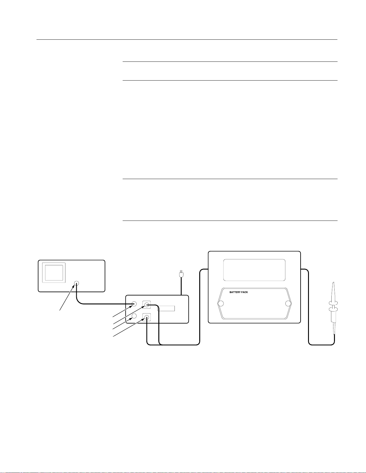
Offset and Noise Check
Perform this check with the A6906S Fiber-Optic Isolation System connected to
an oscilloscope and configured for normal use, as shown in Figure 3 on page 3.
Use the 6-inch ground lead on the probe common lead.
Tektronix TDS 460 Checking noise, rise time,
aberration and bandwidth
Tektronix PG 506A Checking rise time
Tektronix SG 503 Checking bandwidth
Tektronix part number
012-0482-00
Tektronix part number
01 1-0049-01
Tektronix part number
103-0090-00
Signal connection
Signal termination
Various tests
28
1. Short the probe tip to the probe common lead. The connections should now
be configured as shown in Figure 10.
2. On the A69R06, set the ATTENUATOR to 1 : 1 and COUPLING to AC.
3. Set the oscilloscope as follows:
Horizontal 1 ms/div. . . . . . . . . . . . . . . .
Vertical 5 mV/div. . . . . . . . . . . . . . . . . .
Coupling AC. . . . . . . . . . . . . . . . .
Impedance 50 W. . . . . . . . . . . . . . .
BW Limit On (100 MHz). . . . . . . . . . . . . . . .
Measurement RMS and Mean. . . . . . . . . . . . .
Acquisition Mode Sample (Average off). . . . . . . . . .
A6906S Fiber-Optic Isolation System User Manual
Page 45

Appendix B: Performance Verification
4. To measure noise, check that the RMS measurement readout of the
oscilloscope is less than 2.2 mV.
Oscilloscope
Probe
6-inch Ground Lead
A69T06
Fiber-Optic Cable
Coaxial Cable
A69R06
Figure 10: Noise Check Setup
5. Change the oscilloscope acquisition mode to average, and the coupling to
DC.
6. To measure offset,check that the Mean measurement readout of the
oscilloscope is <±10 mV.
7. Unclip the 6-inch ground lead from the probe tip.
Rise Time Check
Perform this check with the A6906S Fiber-Optic Isolation System connected to
an oscilloscope and configured for normal use, as shown in Figure 3 on page 3.
Use the 6-inch ground lead on the probe common lead.
1. Attach a coaxial cable to the fast rise output of the calibration generator.
Attach a 50 W feedthrough termination to the other end of the coaxial cable.
Attach a BNC to Dual Banana Connector to the 50 W feedthrough termination, and connect the A6906S probe to the banana jacks. Make sure the
probe tip is connected to the signal jack and the 6-inch ground lead is
connected to the ground jack. Attach another coaxial cable from the Trigger
Output
should now be configured as shown in Figure 11.
A6906S Fiber-Optic Isolation System User Manual
of the Cal Generator to channel 2 on the oscilloscope. The connections
29
Page 46
Appendix B: Performance Verification
Calibration Generator
Probe
Coaxial Cable
Trig Out
50 W Feedthrough Termination
BNC to Dual Banana Connector
6-inch Ground Lead
A69T06 A69R06
Fiber-Optic Cable
Figure 11: Rise Time Check Setup
2. Set up the oscilloscope as follows:
Oscilloscope
Coaxial Cable
Horizontal 10 ns/div. . . . . . . . . . . . . . . .
Measurement Rise Time. . . . . . . . . . . . .
Trigger Source Channel 2. . . . . . . . . . . .
Trigger Coupling DC. . . . . . . . . .
Channel 1 Channel 2
Vertical 2 mV/div 200 mV/div. . . . . . . . . . . . . . . . . . . . . .
Coupling DC DC. . . . . . . . . . . . . . . . . . . . . . . . . .
Impedance 50 W 50 W. . . . . . . . . . . . . . . . . . . . . . .
BW Limit Off Off. . . . . . . . . . . . . . . . . . . . . . . . .
Averaging On On. . . . . . . . . . . . . . . . . . . . . . . . . .
3. Set up the calibration generator as follows:
Amplitude Fast Rise, Positive Slope, Max Ampl.. . . . . . . . . . . . . . . .
4. On the A69R06, set the ATTENUATOR to 1 : 1 and COUPLING to AC.
5. Adjust the calibration generator pulse amplitude for five divisions of display
on the oscilloscope, and a frequency of 1 MHz. Check that the Rise Time
measurement readout of the oscilloscope is 3.5 ns or less.
30
A6906S Fiber-Optic Isolation System User Manual
Page 47

Bandwidth Check
Appendix B: Performance Verification
Perform this check with the A6906S Fiber-Optic Isolation System connected to
an oscilloscope and configured for normal use, as shown in Figure 3 on page 3.
Use the 6-inch ground lead on the probe common lead.
1. Attach a coaxial cable to the output of the sine wave generator. Attach a
50 W feedthrough termination to the other end of the coaxial cable. Attach a
BNC to Dual Banana Connector to the 50 W feedthrough termination, and
connect the A6906S probe to the banana jacks. Connect the probe tip to the
signal jack and the 6-inch ground lead to the ground jack. The connections
should now be configured as shown in Figure 12.
Sine Wave Generator
Oscilloscope
Probe
Coaxial Cable
50 W Feedthrough Termination
BNC to Dual Banana Connector
6-inch Ground Lead
A69T06
Fiber-Optic Cable
Figure 12: Bandwidth Check Setup
2. Set up the oscilloscope:
Horizontal 5 ms/div. . . . . . . . . . . . . . . .
Vertical 10 mV/div. . . . . . . . . . . . . . . . . .
Coupling DC. . . . . . . . . . . . . . . . .
Impedance 50 W. . . . . . . . . . . . . . .
BW Limit Off. . . . . . . . . . . . . . . .
Acquisition Mode Average (8). . . . . . . . . .
Trigger Source Channel 1. . . . . . . . . . . .
Trigger Coupling DC. . . . . . . . . .
Measurement Peak–Peak. . . . . . . . . . . . .
Coaxial Cable
A69R06
A6906S Fiber-Optic Isolation System User Manual
31
Page 48

Appendix B: Performance Verification
3. On the A69R06, set the ATTENUATOR to 1 : 1 and COUPLING to AC.
4. Set the output of the sine wave generator to a reference frequency of 50 kHz.
5. Adjust the sine wave generator output level so that the Peak-Peak measure-
ment readout of the oscilloscope is 50 mV.
6. Set the oscilloscope horizontal to 5 ns/div.
7. Set the sine wave generator frequency to 100 MHz.
8. Confirm that the Peak-Peak measurement readout on the oscilloscope is
≥35.4 mV.
Gain Check
Perform this check with the A6906S Fiber-Optic Isolation System connected to
an oscilloscope and configured for normal use, as shown in Figure 3 on page 3.
Use the 6-inch ground lead on the probe common lead.
Probe
Coaxial Cable
Calibration Generator
BNC to Dual Banana Connector
6-inch Ground Lead
A69T06
Figure 13: Gain Check Setup
Oscilloscope
Coaxial Cable
A69R06
Fiber-Optic Cable
32
1. Attach a coaxial cable to the standard amplitude output of the calibration
generator. Attach a BNC to Dual Banana Connector to the other end of the
A6906S Fiber-Optic Isolation System User Manual
Page 49

Appendix B: Performance Verification
coaxial cable, and connect the A6906S probe to the banana jacks. Make sure
the probe tip is connected to the signal jack and the 6-inch ground lead is
connected to the ground jack. The connections should now be configured as
shown in Figure 13.
2. Set up the oscilloscope:
Averaging On. . . . . . . . . . . . . . . .
Horizontal 500 ms/div. . . . . . . . . . . . . . . .
Vertical 100 mV/div. . . . . . . . . . . . . . . . . .
Coupling DC. . . . . . . . . . . . . . . . .
Impedance 50 W. . . . . . . . . . . . . . .
BW Limit On (20 MHz). . . . . . . . . . . . . . . .
Measurements Peak-Peak. . . . . . . . . . . . .
Acquisition Mode Hi Res. . . . . . . . . .
3. Set the output of the calibration generator to 10 V.
4. Set the A69R06 ATTENUATOR to 5 : 1 and DC coupling. Adjust the
trigger for a stable display. Use the TDS 460 SET LEVEL TO 50% button.
Check that the oscilloscope Peak-Peak measurement readout is between
488.5 mV and 511.5 mV. Repeat for each of the A69R06 ATTENUATOR
settings. Refer to Table 12 and check that the oscilloscope Peak-Peak
measurement readout is within the limits given.
T able 12: Gain Accuracy Limits
Calibration
ATTENUATOR
Setting
5:1 10 V 100 mV/div 488.5 mV to 511.5 mV
2:1 20 V 100 mV/div 390.8 mV to 409.2mV
1:1 50 V 100 mV/div 488.5 mV to 511.5 mV
1:2 100 V 100 mV/div 486.5 mV to 513.5 mV
1:5 100 V 50 mV/div 194.6 mV to 205.4 mV
1:10 100 V 20 mV/div 97.3 mV to 102.7 mV
1:20 100 V 10 mV/div 48.4 mV to 51.6 mV
1:50 100 V 5 mV/div 19.36 mV to 20.64 mV
Generator
Voltage
Oscilloscope
Vertical Size
Oscilloscope Peak-Peak
Measurement Readout
A6906S Fiber-Optic Isolation System User Manual
33
Page 50

Appendix B: Performance Verification
Probe Check
Perform this check with the A6906S Fiber-Optic Isolation System connected to
an oscilloscope and configured for normal use, as shown in Figure 3 on page 3.
Use the 6-inch ground lead on the probe common lead.
1. Check that the probe readout on the A69R06 has the 100× light turned on.
2. Connect a coaxial cable to the HIGH AMPL (high amplitude) output of a
calibration generator. Attach a BNC to dual banana connector to the other
end of the coaxial cable. Connect the A6906S probe to the BNC to dual
banana connector by attaching the probe tip to the signal side of the BNC to
dual banana connector and attaching the reference common lead to the
ground side. Figure 14 illustrates these connections.
Calibration Generator
Oscilloscope
Probe
Coaxial Cable
50 W Feedthrough Termination
BNC to Dual Banana Connector
6-inch Ground Lead
A69T06 A69R06
Figure 14: Probe Check Setup
3. Set up the oscilloscope:
Horizontal 2 ms/div. . . . . . . . . . . . . . . .
Vertical 10 mV/div. . . . . . . . . . . . . . . . . .
Coupling DC. . . . . . . . . . . . . . . . .
Impedance 50 W. . . . . . . . . . . . . . .
BW Limit On (20 MHz or 100 MHz). . . . . . . . . . . . . . . .
Acquisition Mode Average. . . . . . . . . .
Coaxial Cable
Fiber-Optic Cable
34
A6906S Fiber-Optic Isolation System User Manual
Page 51

Appendix B: Performance Verification
4. Adjust the A69R06 ATTENUATOR to 1 : 1.
5. Set the calibration generator to produce a 10 kHz high-amplitude signal, and
the output amplitude to display a 5 division high waveform on the oscilloscope.
6. Confirm that the flatness of the upper waveform half is within 4% of total
signal amplitude.
A6906S Fiber-Optic Isolation System User Manual
35
Page 52

Appendix B: Performance Verification
36
A6906S Fiber-Optic Isolation System User Manual
Page 53

Appendix C: GPIB Interface Messages
The following explains how the A69R06 reacts to standard interface messages.
Message abbreviations used are from ANSI/IEEE Std 488–1978.
My Talk Address and
My Listen Address
(MTA and MLA)
Go to Local (GTL)
Device Clear (DCL)
Selected Device
Clear (SDC)
Serial Poll Enable and
Disable (SPE and SPD)
The A69R06’s address is established as previously explained in the GPIB
Address and Terminator information. When the A69R06 receives its own address
along with either of these messages, it responds by entering the appropriate state:
ready to talk or ready to listen.
The GTL message sets the A69R06 to local state.
The DCL message reinitializes communication between the A69R06 and the
controller. In response to DCL, the A69R06 clears any input and output
messages as well as any unexecuted control settings. Also cleared are any errors
and events waiting to be reported (except the power-on event). If the SRQ line is
asserted for any reason other than power-on, it becomes unasserted when the
DCL message is received.
The SDC message performs the same function as DCL; however, only instruments that have been listen-addressed respond to SDC.
The SPE message causes the A69R06 to transmit its serial-poll status byte when
it is talk addressed. The SPD message switches the A69R06 back to normal
operation.
Unlisten and Untalk
(UNL and UNT)
Interface Clear (IFC)
A6906S Fiber-Optic Isolation System User Manual
When the UNL message is received, the A69R06’s listen function is placed in an
idle (unaddressed) state. In the idle state, the A69R06 will not accept messages
over the bus until MLA is asserted.
The talk function is placed in an idle state when the A69R06 receives the UNT
message. In this state, the A69R06 cannot transmit via the bus until MTA is
asserted.
When IFC is asserted, both the Talk and Listen functions are placed in an idle
state. This produces the same effect as receiving both the UNT and the UNL
commands.
37
Page 54

Appendix C: GPIB Interface Messages
Remote/Local Functions
The A69R06 is always in one of the following states:
Local. The A69R06 always starts up in local mode when power is first applied.
In addition, the unit switches to local mode from remote mode when one of the
following occurs:
H A front panel operation is performed while in remote mode.
H The REN line goes false.
H The GTL message is received when addressed as a listener.
Remote. When both the ATN and REN lines are true and the A69R06 receives an
MLA message, operation changes from local status to remote status.
38
A6906S Fiber-Optic Isolation System User Manual
Page 55

Warning
The following servicing instructions are for use only by qualified personnel. To
avoid personal injury, do not perform any servicing other than that contained in
the operating instructions unless you are qualified to do so. Refer to General
Safety Summary and Service Safety Summary prior to performing any service.
Page 56

Page 57

Appendix D: Maintenance
Most of the parts of the A6906S Fiber-Optic Isolation System cannot be serviced
by the user. User repair is limited to replacing the following modules:
H The entire A69C06.
H Line fuse in the A69C06.
H The entire A69R06 (replacement requires factory recalibration of all
modules).
H Line fuse in the A69R06.
H The entire A69T06 (replacement requires factory recalibration of all
modules).
H battery pack in the A69T06.
H Probe in the A69T06.
H Fiber-Optic Cable in the A69T06 (replacement with fiber-optic cable of
different length may require factory recalibration of all modules—see
Table 14 on page 46).
NOTE. The A69T06 Transmitter, fiber-optic cable, and A69R06 Receiver are
calibrated at the factory as a matched unit. Tektronix does not warrant
performance to specifications if you exchange modules among A6906S FiberOptic Isolation Systems. Always use an A69T06 and A69R06 having matching
serial numbers.
You can replace a failed module or return it to your Tektronix Service Center for
repair. If you replace the A69T06, A69R06, or in some cases replace the
fiber-optic cable with one of a different length, you must return the entire
A6906S Fiber-Optic Isolation System to your Tektronix Service Center for
calibration or performance to specifications is not warranted.
A6906S Fiber-Optic Isolation System User Manual
41
Page 58

Appendix D: Maintenance
Replacing Fuses
Replacing the Probe
The A69R06 and A69C06 have AC line fuses. The A69T06 and the battery pack
do not have user-replaceable fuses.
CAUTION. To prevent equipment damage, do not substitute a spare fuse from one
assembly for another. The spare fuses for the A69C06 and the A69R06 are not
interchangeable.
The housing for the fuses is a part of the line cord connector in the body of the
A69R06 and A69C06 modules. To remove the fuse, unplug the AC power cord
from the A69R06 or A69C06. Using a small screwdriver, open the fuse case and
replace the fuse. Always replace the fuse with one of the same type and ratings.
You can replace the probe attached to the A69T06 by removing the panel of the
A69T06 that the probe cord passes through. You will need a small PZ1
POSIDRIV screwdriver.
WARNING. To prevent injury or death, do not use the A6906S while the transmitter is open for access to the transmitter sub-unit. Electrical isolation is not
provided and the transmitter sub-unit will be at ground potential of the system
being measured.
1. Remove the panel of the A69T06 by removing the six screws holding it in
place. Pull the panel out slowly, being careful not to put tension on the
fiber-optic cable.
CAUTION. To prevent cable or probe damage, do not pull on the fiber-optic cable
or the fiber-optic cable connectors.
If you need more free length of fiber-optic cable, carefully pull it through the
grommet holding it in the removed panel. Pull slowly and do not exert any
tension on the optical connectors inside the A69T06.
42
A6906S Fiber-Optic Isolation System User Manual
Page 59

Appendix D: Maintenance
2. Pull out the two spacers holding the transmitter sub-unit inside the A69T06.
3. Reach inside the A69T06 and pull the transmitter sub-unit out, but do not
completely remove it from the case of the A69T06. See Figure NO TAG. If
necessary, pull on the probe compensation box (part of the probe connector).
Transmitter
Sub-unit
Probe Cable
Grommet Housing
Toroid
Probe
Connector
Compensation
Box
Spacer
Panel
Figure 15: Replacing the probe
4. Remove the probe from the transmitter sub-unit ELEC INPUT connector by
rotating the probe connector counterclockwise and pulling it off.
5. Remove the probe cord grommet housing from the A69T06 panel by
removing the two screws holding it in place.
6. Remove the two screw and nut assemblies holding together the two halves of
the grommet assembly.
7. Pull the probe out through the A69T06 front panel.
A6906S Fiber-Optic Isolation System User Manual
43
Page 60
Appendix D: Maintenance
8. Remove the probe tip from the probe to allow the probe head to pass through
the toroid.
9. Unwind the probe cable from the toroid inside the probe cable grommet
housing. The toroid improves the high frequency CMRR performance of the
A6906S.
WARNING. To prevent injury or death, do not substitute probes of different types
for the double-insulated probe supplied with the A69T06. Exposed conductive
parts of the probe are at ground potential of the system being measured.
10. Reassemble the A6906S in the reverse order of disassembly.
NOTE. Begin reassembly by winding the probe cable around the toroid. Wind
exactly seven full turns around the toroid, and keep the toroid as close to the
probe compensation box as possible. The strain relief on the probe cable coming
out of the probe compensation box can be part of the cord that is wound around
the toroid.
11. Before completing reassembly of the A69T06, perform a low-frequency
compensation of the new probe, as described in the next section. Perform
this adustment before reinstalling the back panel.
12. After compensating the new probe, complete the assembly by reinstalling the
A69T06 back panel. Two of the six screws for this panel are shorter than the
others; the shorter screws go in the middle height positions on the panel and
the longer screws go in the corners.
44
A6906S Fiber-Optic Isolation System User Manual
Page 61

Appendix D: Maintenance
Probe Compensation
Perform the probe compensation with the A6906S Fiber-Optic Isolation System
configured for normal use.
1. Connect the A6906S probe to the calibrator output of the test oscilloscope.
2. Adjust the A69R06 ATTENUATOR to 5 : 1.
NOTE. The common lead of the A6906S must be connected to a ground connector
on the test oscilloscope for successful completion of the low-frequency probe
compensation.
3. Set the test oscilloscope to display the calibrator signal.
4. Set the horizontal to display at least one full waveform cycle, and set the
vertical so that the waveform amplitude is at least 80% of full screen height.
5. Insert a non-conductive screwdriver into the hole in the A6906S probe
compensation box. Rotate the screwdriver until optimum waveform flatness
is obtained. The probe compensation box is attached to the probe connector
that attaches to the A69T06.
A6906S Fiber-Optic Isolation System User Manual
45
Page 62

Appendix D: Maintenance
Replacing the Fiber-Optic Cable
You can replace the fiber-optic cable with one of the cables listed in Table 13.
CAUTION. To prevent equipment damage, use extreme caution not to damage the
cable or connectors when replacing a fiber-optic cable. If you do not have
experience working with fiber-optic cable and connectors, you are encouraged to
return the A6906S Fiber-Optic Isolation System to a Tektronix Service Center for
cable replacement and calibration.
T able 13: Available Fiber-Optic Cables
Fiber-Optic Cable Length Cable Type A Cable Type B
3m 174-3152-00 174-3152-01
10 m 174-2924-01 174-2924-02
20 m 174-2925-01 174-2925-02
100 m 174-2926-01 174-2926-02
200 m 174-2927-01 174-2927-02
NOTE. If you replace the fiber-optic cable with a different length than previously
installed, you may need to return the complete A6906S Fiber-Optic Isolation
System to a Tektronix Service Center. Performance to specifications is not
warranted unless calibrated by Tektronix.
Table 14 lists cable length changes that require system recalibration.
T able 14: Fiber-Optic Cable Changes Requiring Recalibration
Fiber-Optic
Cable Length
from 3 m recalibrate recalibrate
from 10 m recalibrate recalibrate
from 20 m recalibrate recalibrate
to 3 m to 10 m to 20m to 100 m to 200 m
46
from 100 m recalibrate recalibrate recalibrate recalibrate
from 200 m recalibrate recalibrate recalibrate recalibrate
A6906S Fiber-Optic Isolation System User Manual
Page 63
Appendix D: Maintenance
To replace the fiber-optic cable, remove the panel of the A69T06 that the probe
cord passes through using a small PZ1 POSIDRIV screwdriver.
CAUTION. Before removing the fiber-optic cable from the A69T06, make sure the
other end of the cable is disconnected from the A69R06 and the cable connectors
at that end have the protective caps in place. Replace the optical connector
covers on the A69R06 whenever the fiber-optic cable is disconnected.
Transmitter Panel
Removal
Refer to Figure 16 when removing the transmitter panel.
CAUTION. Before removing the fiber-optic cable from the A69T06, make sure the
other end of the cable is disconnected from the A69R06 and the cable connectors
at that end have the protective caps in place. Replace the optical connector
covers on the A69R06 whenever the fiber-optic cable is disconnected.
1. Remove the panel of the A69T06 by unscrewing and removing the six
screws that hold it in place. Pull the panel out slowly, being careful not to
pull on the fiber-optic cable.
CAUTION. Do not pull on the fiber-optic cable or the fiber-optic cable connectors. Excessive strain can damage the fiber-optic cable or probe.
2. Pull out the two spacers holding the transmitter sub-unit inside the A69T06.
Reach inside the A69T06 and pull the transmitter sub-unit out, but do not
completely remove it from the case of the A69T06. If necessary, you may
grasp and pull on the probe compensation box which is part of the probe
connector.
WARNING. While the A69T06 Transmitter is open for access to the transmitter
sub-unit, electrical isolation is not provided and the transmitter sub-unit will be
at ground potential of the system being measured. Do not use the A6906S in a
floating-ground mode, or use it to measure hazardous voltages, while the
A69T06 is open.
3. Disconnect the probe from the ELEC INPUT connector on the transmitter
sub-unit by twisting the probe connector counterclockwise and pulling it off.
A6906S Fiber-Optic Isolation System User Manual
47
Page 64

Appendix D: Maintenance
Transmitter Sub-unit
Probe Connector
Probe Compensation Box
Figure 16: Removing the Panel
Panel
Grommet
Optical
Connector
Spacer
Fiber-optic Cable Removal
48
If you are replacing a fiber-optic cable perform steps 1
to 3. If this is a first-time
installation, perform step 2.
1. Remove the fiber-optic cable from the transmitter sub-unit by unscrewing the
two optical connectors. Pull off the connectors along with the cable strain
release.
2. Remove the optical cable grommet from the A69T06 panel by removing the
two screws holding it in place. Once unscrewed, the grommet will disassemble into two pieces.
3. Pull out one connector at a time through the A69T06 panel.
A6906S Fiber-Optic Isolation System User Manual
Page 65

Appendix D: Maintenance
Fiber-optic Cable
Installation
(OPTICAL FIBER
The installation procedure varies depending on whether the fiber-optic cable is
type A or B as shown in Table 13 on page 46.
Installation for Fiber-optic Cable Type A
See Figure17 for installing the fiber-optic cable type A.
Hole
CABLE)
Sleeve
Strain relief
Panel
Probe
Fiber-optic cable
Grommet
White protective cap for
SIGNAL connector
To the connector
on the transmitter
sub-unit
Red protective cap for
COMMAND connector
Figure 17: Fiber-optic Cable Installation (for Type A)
1. Pass one of the optical connectors from outside to inside through the hole
labeled OPTICAL FIBER CABLE on the panel.
A6906S Fiber-Optic Isolation System User Manual
49
Page 66

Appendix D: Maintenance
CAUTION. You cannot pass the other connectors through the hole unless the
protective caps are removed. To prevent damage, be careful not to get the
connectors dirty.
2. Remove the protective cap from the other connector, and then pass that
connector from outside to inside through the hole on the panel.
3. Pass the strain relief from outside to inside through the hole on the panel.
4. Connect the SIGNAL connector (with white protective cap) of the fiber-op-
tic cable to the OPTICAL SIGNAL INPUT connector on the transmit
sub-unit.
5. Place the cable strain relief around the OPTICAL COMMAND INPUT
connector on the transmit sub-unit, as show in Figure 18.
Strain relief on one connector only
50
Figure 18: Connection of the Fiber-optic Cable and Connector
6. Connect the COMMAND connector (with red protective cap) of the
fiber-optic cable to the OPTICAL COMMAND INPUT connector on the
transmit sub-unit. Verify that the cable strain relief is firmly seated between
the connectors.
A6906S Fiber-Optic Isolation System User Manual
Page 67

Installation for Fiber-optic Cable Type B
See Figure 19 for installing the fiber-optic cable type B.
Panel
Hole
(OPTICAL FIBER
CABLE)
Sleeve
Appendix D: Maintenance
Probe
Strain relief
White protective cap for
SIGNAL connector
To the connector
on the transmitter
sub-unit
Grommet
Red protective cap for
COMMAND connector
Fiber-optic cable
Figure 19: Fiber-optic Cable Installation (for Type B)
1. Pass one of the optical connectors from outside to inside through the hole
labeled OPTICAL FIBER CABLE on the panel.
CAUTION. You cannot pass the other connector through the hole unless the
protective cap is removed. To prevent equipment damage, be careful not to get
the connector dirty.
2. Remove the protective cap from the other connector, and then pass that
connector from outside to inside through the hole on the panel.
A6906S Fiber-Optic Isolation System User Manual
51
Page 68
Appendix D: Maintenance
3. Move the strain relief backward from the sleeve of the fiber-optic cable, and
then pass the whole sleeve completely through the hole on the panel.
4. As slightly bending the end of the strain relief where the fiber-optic cable is
passing through, pass the whole strain relief from outside to inside through
the hole on the panel.
5. Connect the SIGNAL connector (with white protective cap) of the fiber-op-
tic cable to the OPTICAL SIGNAL INPUT connector on the transmit
sub-unit.
6. Place the cable strain relief around the OPTICAL COMMAND INPUT
connector on the transmit sub-unit, as show in Figure18.
7. Connect the COMMAND connector (with red protective cap) of the
fiber-optic cable to the OPTICAL COMMAND INPUT connector on the
transmit sub-unit. Verify that the cable strain relief is firmly seated between
the connectors.
Panel Installation
Calibration
1. Cover the fiber-optic cable sleeve with two pieces of optical cable grommet
while observing the orientation of the grommet in the panel; the long end
points away from the transmitter sub-unit, and then install the grommet into
the panel as was being installed before.
2. Connect the probe to the ELEC INPUT connector on the transmitter
sub-unit.
CAUTION. When re-installing the panel, be careful not to put the fiber-optic cable
between the panel and the cabinet.
3. Re-install the panel of the A69T06 by screwing the six screws. Two of the
six screws for the panel are shorter than the others; the shorter screws go into
the middle height positions on the panel and the longer screws go into the
corners.
Perform the performance check for the A6906S instrument as described in
Appendix B: Performance Verification.
52
A6906S Fiber-Optic Isolation System User Manual
Page 69

Appendix E: Replaceable Parts List
This section contains a list of the components that are replaceable for the
A6906S Fiber-Optic Isolation System. As described below, use these lists to
identify and order replacement parts.
Parts Ordering Information
Replacement parts are available from or through your local Tektronix, Inc.,
service center or representative.
Changes to Tektronix instruments are sometimes made to accommodate
improved components as they become available and to give you the benefit of
the latest circuit improvements. Therefore, when ordering parts, it is important to
include the following information in your order:
H Part number.
H Instrument type or model number.
H Instrument serial number.
H Instrument modification number, if applicable.
If a part you order has been replaced with a different or improved part, your local
Tektronix service center or representative will contact you concerning any
change in the part number.
Using the Replaceable Parts List
The tabular information in the Replaceable Parts List is arranged for quick
retrieval. Understanding the structure and features of the list will help you find
all the information you need for ordering replacement parts.
Item Names
In the Replaceable Parts List, an Item Name is separated from the description by
a colon (:). Because of space limitations, an Item Name may sometimes appear
as incomplete. For further Item Name identification, U.S. Federal Cataloging
Handbook H6–1 can be used where possible.
A6906S Fiber-Optic Isolation System User Manual
53
Page 70

Appendix E: Replaceable Parts List
Indentation System
Abbreviations
This parts list is indented to show the relationship between items. The following
example is of the indentation system used in the Description column:
1 2 3 4 5 Name & Description
Assembly and/or Component
Attaching parts for Assembly and/or Component
(END ATTACHING PARTS)
Detail Part of Assembly and/or Component
Attaching parts for Detail Part
(END ATTACHING PARTS)
Parts of Detail Part
Attaching parts for Parts of Detail Part
(END ATTACHING PARTS)
Attaching parts always appear at the same indentation as the item it mounts,
while the detail parts are indented to the right. Indented items are part of, and
included with, the next higher indentation. Attaching parts must be purchased
separately, unless otherwise specified.
Abbreviations conform to American National Standards Institute (ANSI)
standard Y1.1.
CROSS INDEX – MFR. CODE NUMBER TO MANUFACTURER
S3109
TK0191 SONY/TEKTRONIX PO BOX 5209,
TK2541 AMERICOR ELECTRONICS LTD 2682 W COYLE AVENUE ELK GROVE VILLAGE IL 60007
0B445 ELECTRI–CORD MFG CO INC 312 EAST MAIN ST WESTFIELD PA 16950
64537 KDI ELECTRONICS INC
80009 TEKTRONIX INC 14150 SW KARL BRAUN DR
FELLER 72 Veronica Ave
Unit 4
TOKYO INTERNATIONAL
31 FARINELLA DR EAST HANOVER NJ 07936
SUBSIDIARY OF KDI CORP
PO BOX 500
Summerset NJ 08873
TOKYO JAPAN 100–31
BEAVERT ON OR 97077–0001
54
A6906S Fiber-Optic Isolation System User Manual
Page 71

Appendix E: Replaceable Parts List
Fig. &
Index
No.
16–1
–2 650–3122–00
–3 650–3022–00 1 BATTERY PACK AS:6V 12AH,SHIELDED LEAD–ACID
–4 159–0345–00 1 FUSE,CARTRIDGE:DIN,1A,250V,FAST 80009 159034500
–5 159–0260–00 1 FUSE,CARTRIDGE:2A,250V,MEDIUM 80009 159026000
–6 650–3063–00 1 RECEIVER: A69R06 80009 650306300
–7 174–3152–00
–8 200–4146–00 2 COVER,DUST:FC TYPE FBR OPT CONN,WHITE 80009 200414600
–9 650–3064–00 1 BATTERY CHARGER: A69C06 80009 650306400
–10 206–0461–00 1 PROBE,HEAD:100X,BLACK
–11 013–0107–08 1 TIP,PROBE:MINIATURE/COMPACT SIZE,BLACK
–12 200–4147–00 2 COVER,DUST:FC TYPE FBR OPT CONN,RED 80009 200414700
–13 200–4173–00 2 CAP,DUST:FC TYPE OPT FBR CONN,PLASTIC 80009 200417300
Tektronix
Part No.
010–0568–00 1 PROBE,PASSIVE:DOUBLE INSULA TED,100X
650–3122–01
650–3123–00
650–3123–01
174–2925–01
174–2926–01
174–2927–01
174–2924–01
Serial No.
Effective Dscont
J300000
J300291
J300000
J300291
J300290
J300290
Qty
12345 Name & Description
(ALSO INCLUDES 16-10 AND 16-11)
1
TRANSMITTER:W/INSULA TING BOX (A69T06)
(STANDARD ONLY)
1
TRANSMITTER:W/INSULA TING BOX (A69T06)
(STANDARD ONLY)
1
TRANSMITTER:W/INSULA TING BOX (A69T06;03)
(OPTION 03 ONLY)
1
TRANSMITTER:W/INSULA TING BOX (A69T06;03)
(OPTION 03 ONLY)
BATTERY
CA ASSY,FBR OPT:3M L,MULTIMODE,FC TO FC
1
(STANDARD ONLY)
CA ASSY,FBR OPT:20M L,MULTIMODE,FC TO FC,
1
W/TENSION RELIEF
(OPTION 01 ONLY)
CA ASSY,FBR OPT:100M L,MULTIMODE,FC TO FC,
1
W/TENSION RELIEF
(OPTION 02 ONLY)
CA ASSY,FBR OPT:200M L,MULTIMODE,FC TO FC,
1
W/TENSION RELIEF
(OPTION 03 ONLY)
CA ASSY,FBR OPT:10M L,MULTIMODE,FC TO FC,
1
W/TENSION RELIEF
(OPTION 04 ONLY)
(PART OF 16–1)
(PART OF 16–1)
Mfr.
Code
80009 010056800
80009
80009
80009
80009
80009 650302200
80009
80009
80009
80009
80009
80009 206046100
80009 013010708
Mfr. Part No.
650312200
650312201
650312300
650312301
174315200
174292501
174292601
174292701
174292401
A6906S Fiber-Optic Isolation System User Manual
55
Page 72

Appendix E: Replaceable Parts List
1
2
Figure 20: Replaceable Parts
56
A6906S Fiber-Optic Isolation System User Manual
Page 73

Appendix E: Replaceable Parts List
Figure 21: Accessories
Fig. &
Index
No.
21–
–1 011–0049–01 1 TERMN,COAXIAL:50 OHM,2W,BNC 64537 T132DS
–2 012–1392–00 1 LEAD,SET :(1) SIGNAL,(1) GROUND 80009 012139200
–3 012–0057–01 1 CA ASSY ,RF:COAXIAL,;RFD,50 OHM,43 L,BNC,MALE,STR,
–4 196–3422–00 J300406 1 LEAD,ELECTRICAL23 AWG,6.000 L,BLACK PVC TK0191 196342200
Tektronix
Part No.
016–1218–00 1 CLEANER:2.5MM DIA X 130MM L,CHEMICAL TEXTILE,
161–0066–00 2 CABLE ASSY,PWR,:3,18A WG,98 L,SVT,GREY/BLK,60
161–0066–09 2 CABLE ASSY,PWR,:3,0.75MM SQ,220V,99.0 L EUROPEAN
161–0066–10 2 CABLE ASSY,PWR,:3,0.1MM SQ,250VOLT ,2.5 METERS
161–0066–11 2 CABLE ASSY,PWR,:3,1.00MM SQUARED,250V,10 AMP,
161–0066–12 2 CABLE ASSY,PWR,:3,18 AWG,98 L,SVT,GREY/BLK,
Serial No.
Effective Dscont
Qty
12345 Name & Description
STANDARD ACCESSORIES
BOTH ENDS,W/STRAIN RELIEF BOOT BOTH ENDS
STICK–TYPE,5 PIECES
DEG C,IEC BME X STR,IEC RCPT ,10A/125V
(STANDARD ONLY)
(OPTION A1–EUR0PEAN)
LONG,UNITED KINGDOM,STR IEC–320 RCPT ,13 AMP
FUSED UK PLUG
(OPTION A2–UNITED KINGDOM)
2.5METERS LONG,AUSTRALIA, (STRAIGHT)
(OPTION A3–AUSTRALIAN)
60 DEG C,BME X STR,IEC RCPT ,10A/250V
(OPTION A4–NORTH AMERICAN)
Mfr.
Code
80009 012005701
80009 016121800
0B445 ECM–161–0066–00
S3109 86511000
S3109 BS/13–H05VVF3G0
S3109 198–000
TK2541 13E68,25–1E–250
Mfr. Part No.
A6906S Fiber-Optic Isolation System User Manual
57
Page 74

Appendix E: Replaceable Parts List
Fig. &
Index
No.
Tektronix
Part No.
161–0154–00 2 CABLE ASSY,PWR,:3,1.00MM SQ,250V,10A,2.5 METER
159–0260–00 1 FUSE,CARTRIDGE:2A,250V,MEDIUM 80009 159026000
159–0345–00 1 FUSE,CARTRIDGE:DIN,1A,250V,FAST 80009 159034500
070–8900–04 1 MANUAL,TECH:USER A6906S 80009 070890004
011–0055–01 1 TERM,COAXIAL:75 OHM,1W,BNC 80009 011005501
012–0991–00 1 CABLE,COMPOSITE:IDC,GBIB,2 METER,24 COND 80009 012099100
012–0074–00 1 CA ASSY,RF:COAXIAL,RFD,75 OHM 80009 012007400
016–1208–00 1 CLEANER:2.5 MM DIA X 130 MM L TEXTILE,STICK–TYPE,
252–0408–00 1 OIL:INDEX MATCHING OIL FOR OPT CONN 80009 252040800
Serial No.
Effective Dscont
Qty
(OPTION A5–SWISS)
OPTIONAL ACCESSORIES
200 PIECES
Mfr.
Code12345 Name & Description
S3109 12–H05VVF3G 00–
80009 016120800
Mfr. Part No.
58
A6906S Fiber-Optic Isolation System User Manual
Page 75

Glossary
Amplification
The degree of increase in amplitude as a signal passes through a device such
as a probe or amplifier. That is, the ratio of the output measure to the input
measure. For example, a ×5 amplifier will magnify, or increase, the input
signal’s voltage by a factor of 5. Amplification is the reciprocal of attenuation.
Attenuation
The degree of reduction in amplitude as a signal passes through a device
such as a probe or attenuator. That is, the ratio of the input measure to the
output measure. For example, 100× probe will attenuate, or reduce, the input
signal’s voltage by a factor of 100. Attenuation is the reciprocal of amplification.
Bandwidth
The frequency range within which an instrument’s performance with regard
to a particular characteristic falls within specified limits, usually –3 dB.
Controller
A computer that controls the action of one or more peripheral devices.
Coupling
The association of two or more systems or circuits for the transfer of power
or information from one to the other.
Fiber-Optic Cable
A cable of one or more conductors that carry information in the form of the
relative intensity of a signal of light.
Floating Ground
A system where signal ground is connected to a potential that is different
than earth ground.
Frequency
The reciprocal of the time period. Measured in Hertz (Hz) where 1 Hz = 1
cycle per second.
Gain
See Amplification.
GPIB (General Purpose Interface Bus)
An interconnection bus and protocol that allows you to connect multiple
instruments in a network under the control of a controller. Also known as
IEEE 488 bus. Transfers data with eight parallel data lines, five control lines,
and three handshake lines.
A6906S Fiber-Optic Isolation System User Manual
59
Page 76

Glossary
Isolation
Electrical insulation between the input signal ground of a measurement
system and earth ground. Usually, the output of an isolation system grounds
the output signal to the earth ground.
Oscilloscope
An instrument for making a graph of two factors, usually voltage versus
time.
Probe
An input device that connects test and measurement equipment to a circuit
under test.
Query
A type of command that requests a specified condition or status of the
instrument.
S/N Ratio
The ratio of the signal level to the noise level of a waveform.
SRQ
A Service ReQuest is initiated by the A69R06 in response to some internal
event, in order to call this event to the attention of an external controller
connected to the GPIB interface.
60
A6906S Fiber-Optic Isolation System User Manual
Page 77

Index
Numbers
50 Ohm OUTPUT connector, 4, 5
75 Ohm OUTPUT connector, 4, 5
A
AC light, 10
AC power, 1
Accessories
optional, ix
standard, ix
ATTENUATOR button, 9
B
Basic operation, 7
Battery Pack, charging, 1
Block diagram, interconnections, 3
Button
ATTENUAT OR, 9
COUPLING, 10
OFF, 1
SET?, 20
STAndby, 20
TESt, 21
TRAns, 21
Compensation, probe, 44
Computer. See Controller, GPIB
Connections, 3
Connector
50 Ohm OUTPUT, 4, 5
75 Ohm OUTPUT, 4, 5
COMMAND, 4
IEEE Std 488.1–1987, 13
OUTPUT, 2
SIGNAL, 4
Controller, GPIB, 13
COUPLING button, 10
COUpling command, 17
Customer support, x
D
DC light, 10
Description, product, vii
Display, Er1, 7
C
Cable
fiber-optic, 3, 11
IEEE Std 488.1–1987, 13
stacking GPIB, 13
Calibration, 7
T erminating 50 Ohm OUTPUT connector, 7
CALibration command, 16
CHARGE light, 2
Charging battery pack, 1
Cleaning, fiber-optic cable connectors, 11
Command, GPIB syntax, 15
COMMAND connector, 4
Commands
CALibration, 16
COUpling, 17
EVEnt?, 17
HELp?, 17
ID?, 18
INIt, 18
PRObe?, 18
RANge, 19
RQS, 19
E
Er1 display, 7
Event codes, 22
EVEnt? command, 17
F
FAIL light, 8
Fiber-optic cable
connecting, 3
connector cleaning, 11
replacing, 45
Fuses, 41
G
GPIB
address, 14
command syntax, 15
configurations, 14
connection rules, 14
A6906S Fiber-Optic Isolation System User Manual
61
Page 78

Index
connector, 13
event codes, 22
interface functions, 26
interface messages, 37
operation, 13
parameters, 14
status bytes, 22
terminator, 15
H
HELp? command, 17
Horizontal size, 10
I
ID? command, 18
IEEE Std 488.1–1987, 13
INIt command, 18
Interconnections, 3
Interface functions, GPIB, 26
Interface messages, GPIB, 37
L
Light
AC, 10
CHARGE, 2
DC, 10
FAIL, 8
PASS, 7
POWER, 1
Line power, 1
PASS light, 7
Performance verification, 27
Power, line, 1
POWER light, 1
POWER OFF/ON switch, 7
Power on, 7
Probe, replacing, 42
Probe compensation, 44
PRObe? command, 18
Product description, vii
R
RANge command, 19
Replaceable parts, 49–54
Replacing
fiber-optic cable, 45
probe, 42
RQS command, 19
S
Safety information, v
SET? command, 20
SIGNAL connector, 4
Size, displayed, 10
Specifications, 23
Standard, IEEE Std 488.1–1987, 13
Standard accessories, ix
STAndby command, 20
Status bytes, 22
Switch, POWER OFF/ON, 7
Syntax, GPIB command, 15
O
OFF button, 1
Operation, 7
Optional accessories, ix
Options, viii
Oscilloscope
connecting, 4
controls, 10
OUTPUT connector, 2
P
Parts, replaceable, 49–54
62
T
TESt command, 21
TRAns command, 21
Triggering, 10
V
Vertical size, 10
A6906S Fiber-Optic Isolation System User Manual
 Loading...