

Page 1

Instructions
A6303 & A6303XL
100 Amp AC/DC Current Probe
070-3906-06
Warning
The servicing instructions are for use by qualified
personnel only. To avoid personal injury, do not
perform any servicing unless you are qualified to
do so. Refer to all safety summaries prior to
performing service.
www.tektronix.com
Page 2

Copyright © Tektronix, Inc. All rights reserved.
Tektronix products are covered by U.S. and foreign patents, issued and pending. Information in this publication supercedes
that in all previously published material. Specifications and price change privileges reserved.
Tektronix, Inc., P.O. Box 500, Beaverton, OR 97077
TEKTRONIX and TEK are registered tradem arks of Tektronix, Inc.
Page 3

WARRANTY
Tektronix warrants that the products that it m anufactures and sells will be free from defects in materials and
workmanship for a period of one (1) year from the date of shipment. If a product proves defective during this
warranty period, Tektronix, at its option, either will repair the defective product without charge for parts and labor,
or will provide a replacement in exchange for the defective product.
In order to obtain service under this warranty, Customer must notify Tektronix of the defect before the expiration
of the warranty period and make suitable arrangements for the performance of service. Customer shall be
responsible for packaging and shipping the defective product to the service center designated by Tektronix, with
shipping charges prepaid. Tektronix shall pay for the return of the product to Customer if the shipment is to a
location within the country in which the Tektronix service center is located. Customer shall be responsible for
paying all shipping charges, duties, taxes, and any other charges for products returned to any other locations.
This warranty shall not apply to any defect, failure or damage caused by improper use or improper or inadequate
maintenance and care. Tektronix shall not be obligated to furnish service under this warranty a) to repair dam age
resulting from attempts by personnel other than Tektronix representatives to install, repair or service the product;
b) to repair damage resulting from improper use or connection to incompatible equipment; c) to repair any
damage or malfunction caused by the use of non-Tektronix supplies; or d) to service a product that has been
modified or integrated with other products when the effect of such modification or integration increases the time
or difficulty of servicing the product.
THIS W ARRANTY IS GIVEN BY TEKTRONIX IN LIEU OF ANY OTHER WARRANTIES, EXPRESS
OR IMPLIED. TEKTRONIX AND ITS VENDORS DISCLAIM ANY IMPLIED WARRANTIES OF
MERCHANTABILITY OR FITNESS FOR A PARTICULAR PURPOSE. TEKTRONIX’
RESPONSIBILITY TO REPAIR OR REPLACE DEFECTIVE PRODUCTS IS THE SOLE AND
EXCLUSIVE REMEDY PROVIDED TO THE CUSTOMER FOR BREACH OF THIS WARRANTY.
TEKTRONIX AND ITS VENDORS WILL NOT BE LIABLE FOR ANY INDIRECT, SPECIAL,
INCIDENTAL, OR CONSEQUENTIAL DAMAGES IRRESPECTIVE OF WHETHER TEKTRONIX OR
THE VENDOR HAS ADVANCE NOTICE OF THE POSSIBILITY OF SUCH DAMAGES.
Page 4

Page 5

Table of Contents
General Safety Summary ii...................................
Service Safety Summary iv....................................
Preface v...................................................
Contacting Tektronix vi.............................................
Getting Started 1............................................
Probe Installation 1................................................
Operating the Current Probe Slide 2...................................
Degaussing and Autobalancing the Current Probe 3......................
Why Degauss the Current Probe? 3...................................
Maximum Current Limits 4..........................................
Specifications 6.............................................
Maintenance 11..............................................
Cleaning 11.......................................................
Disassembly Instructions 11..........................................
Obtaining Replacement Parts 13.......................................
Preparation for Shipment 14..........................................
Replaceable Parts List 15......................................
Parts Ordering Information 15.........................................
Using the Replaceable Parts List 15....................................
A6303 & A6303XL Instructions
i
Page 6

General Safety Summary
Review the following safety precautions to avoid injury and prevent damage to
this product or any products connected to it. To avoid potential hazards, use this
product only as specified.
Only qualified personnel should perform service procedures.
ToAvoidFireor
Personal Injury
Connect and Disconnect Properly. Do not connect or disconnect probes or test
leads while they are connected to a voltage source.
Ground the Product. This product is indirectly grounded through the grounding
conductor of the mainframe power cord. To avoid electric shock, the grounding
conductor must be connected to earth ground. Before making connections to the
input or output terminals of the product, ensure that the product is properly
grounded.
Observe All Terminal Ratings. To avoid fire or shock hazard, observe all ratings
and marking on the product. Consult the product manual for further ratings
information before making connections to the product.
The common terminal is at ground potential. Do not connect the common
terminal to elevated voltages.
Do Not Operate Without Covers. Do not operate this product with covers or panels
removed.
Avoid Exposed Circuitry. Do not touch exposed connections and components
when power is present.
Do Not Operate With Suspected Failures. If you suspect there is damage to this
product, have it inspected by qualified service personnel.
Do Not Operate in Wet/Damp Conditions.
Do Not Operate in an Explosive Atmosphere.
Keep Product Surfaces Clean and Dry.
ii
A6303 & A6303XL Instructions
Page 7

General Safety Summary
Symbols and Terms
Terms in this Manual. These terms may appear in this manual:
WARNING. Warning statements identify conditions or practices that could result
in injury or loss of life.
CAUTION. Caution statements identify conditions or practices that could result in
damage to this product or other property.
Terms on the Product. These terms may appear on the product:
DANGER indicates an injury hazard immediately accessible as you read the
marking.
WARNING indicates an injury hazard not immediately accessible as you read the
marking.
CAUTION indicates a hazard to property including the product.
Symbols on the Product. The following symbols may appear on the product:
CAUTION
Refer to Manual
Breakable.
Do not drop.
WARNING
High Voltage
Double
Insulated
Protective Ground
(Earth) Terminal
Do not connect to or
remove from an
uninsulated conductor that
is HAZARDOUS LIVE.
A6303 & A6303XL Instructions
iii
Page 8

Service Safety Summary
Only qualified personnel should perform service procedures. Read this Service
Safety Summary and the General Safety Summary before performing any service
procedures.
Do Not Service Alone. Do not perform internal service or adjustments of this
product unless another person capable of rendering first aid and resuscitation is
present.
iv
A6303 & A6303XL Instructions
Page 9

Preface
This instructions manual supports the operation and maintenance of the A6312
Current Probe with any of the AM503 series current probe amplifiers.
You can find additional documentation supporting the operation and maintenance
of the AM503 series amplifiers in the following manuals:
H AM503 Instruction Manual (070-2052-XX)
H AM503S (AM503A) User Manual (070-8170-XX)
H AM503S (AM503A) Service Manual (070-8174-XX)
H AM503B & AM5030 Instruction Manual (070-8766-XX)
A6303 & A6303XL Instructions
v
Page 10

Preface
Contacting Tektronix
Phone 1-800-833-9200*
Address Tektronix, Inc.
Department or name (if known)
14200 SW Karl Braun Drive
P.O. Box 500
Beaverton, OR 97077
USA
Web site www.tektronix.com
Sales support 1-800-833-9200, select option 1*
Service support 1-800-833-9200, select option 2*
Technical support Email: techsupport@tektronix.com
1-800-833-9200, select option 3*
6:00 a.m. -- 5:00 p.m. Pacific time
* This phone number is toll free in North America. After office hours, pl ease leave a
voice mail message.
Outside North America, contact a Tektronix sales office or distributor; see the
Tektronix web site for a list of offices.
vi
A6303 & A6303XL Instructions
Page 11
Getting Started
This section covers the installation and operation of the A6303 & A6303XL
current probes.
The A6303 is a DC to 15 MHz current probe designed for use with the AM503
family of current probe amplifiers and the 11A16 plug-in. The A6303 can
measure currents to 100 A (DC + peak AC), and up to 500 A peak current (while
not exceeding the amp-second rating).
The A6303XL is an extended length cable version of the A6303. It offers the
same current ranges as the A6303 with a diminished frequency range of DC to
10 MHz. The A6303XL can only be used with the AM503B and AM5030, and
will not be recognized by other current probe amplifiers.
Please refer to the amplifier documentation for verification procedures, adjustments, and additional specifications.
If you need assistance using your probe, please call our Customer Support Center
at 1-800-833-9200 and select option 3. If you are outside the United States or
Canada, please contact your nearest Tektronix Service Center.
Probe Installation
To connect a current probe to the Amplifier input connector, align the tab of the
probe connector with the slot in the Amplifier INPUT connector as shown in
Figure 1(a). Align the dot on the probe connector with the groove opening of the
input connector as shown in Figure 1(b). Push the probe connector in while
twisting the barrel clockwise to lock the connector.
CAUTION. Handle current probes with care. Do not drop a probe or subject it to
impact, or the core may crack. Do not connect or disconnect a current probe
while the probe is clamped around a live conductor or while the Amplifier is
powered on, or the probe may suffer electrical damage.
A6303 & A6303XL Instructions
1
Page 12

Getting Started
Amplifier
Push connector in
and twist to lock
Current probe connector
Tab
Slot
(a) Align the tab with the connector slot
Figure 1: Connecting a current probe to the amplifier
Operating the Current Probe Slide
Each current probe has a slide that opens and closes the probe jaw. This allows
you to clamp the probe around a conductor under test. The slide must be locked
to accurately measure current or to degauss the probe. If a probe is unlocked, the
PROBE OPEN indicator on the Amplifier will light.
WARNING. When the probe slides are open, the exposed ferrite core pieces are
not insulated.
To avoid injury or equipment damage, remove power from an uninsulated wire
before clamping the current probe around it.
Current probe
Connector
Amplifier
(b) Insert the connector into the Amplifier
Groove
Alignment dot
Never disconnect the probe from the Amplifier when the probe is connected to a
live conductor.
Allow your hands to contact the probe handle and lock only.
Figure 2 illustrates the slide operation of the probe. To open the probe, press the
bottom of the lock button and squeeze the handle until the core is open. To lock
the probe, release the squeeze handle and press the top of the lock button.
2
A6303 & A6303XL Instructions
Page 13

(1) Unlock the probe
(2) Squeeze
the handle
(a) Opening the probe
Getting Started
(2) Lock the probe
(1) Release the handle
(b) Closing and locking the probe
Figure 2: Operating the probe slide
Degaussing and Autobalancing the Current Probe
1. Verify that the current probe is connected to the Amplifier.
2. Remove the current probe from the conductor under test.
3. Lock the probe slide closed as shown in Figure 2(b).
4. Press the Amplifier PROBE DEGAUSS AUTOBALANCE button.
NOTE. The degauss procedure will fail if the Amplifier is not properly connected
toa50Ω termination impedance.
After you have completed the oscilloscope adjustments and the Amplifier
degauss/autobalance procedure, your system is ready to measure current.
Why Degauss the Current Probe?
Degaussing the probe removes any residual magnetization from the probe core.
Such residual magnetization can induce measurement error. Autobalancing
removes unwanted DC offsets in the amplifier circuitry.
A6303 & A6303XL Instructions
3
Page 14

Getting Started
Failure to degauss the probe is a leading cause of measurement errors. To
maintain measurement accuracy, degauss your probe in each of these cases:
H After turning on the Amplifier and allowing a 20-minute warm-up period.
H Before connecting the probe to a conductor, or changing conductors under
H Whenever an overload condition occurs.
H Whenever the probe is subjected to a strong external magnetic field.
H Periodically during normal use.
Maximum Current Limits
Current probes have three maximum current ratings: continuous, pulsed, and
Ampere-second product. Exceeding any of these ratings can cause measurement
errors or probe heating. See Specifications on page 6 for probe current ratings.
test.
H Maximum Continuous Current refers to the maximum current that can be
continuously measured at DC or at a specified AC frequency. The maximum
continuous current value is derated with frequency; as the frequency
increases, the maximum continuous current rating decreases.
H Maximum Pulsed Current refers to the maximum peak value of pulsed
current the probe can accurately measure, regardless of how short (within
bandwidth limitations) the pulse duration is.
H Ampere-Second Product defines the maximum width of pulsed current that
you can measure when the pulse amplitude is between the maximum
continuous and maximum pulsed current specifications. The maximum
continuous specification itself varies with frequency.
NOTE. Always degauss the probe after measuring a current that exceeds the
maximum continuous current, maximum pulsed current, or Ampere-second
product rating of the probe. Exceeding these ratings can magnetize the probe
and cause measurement errors.
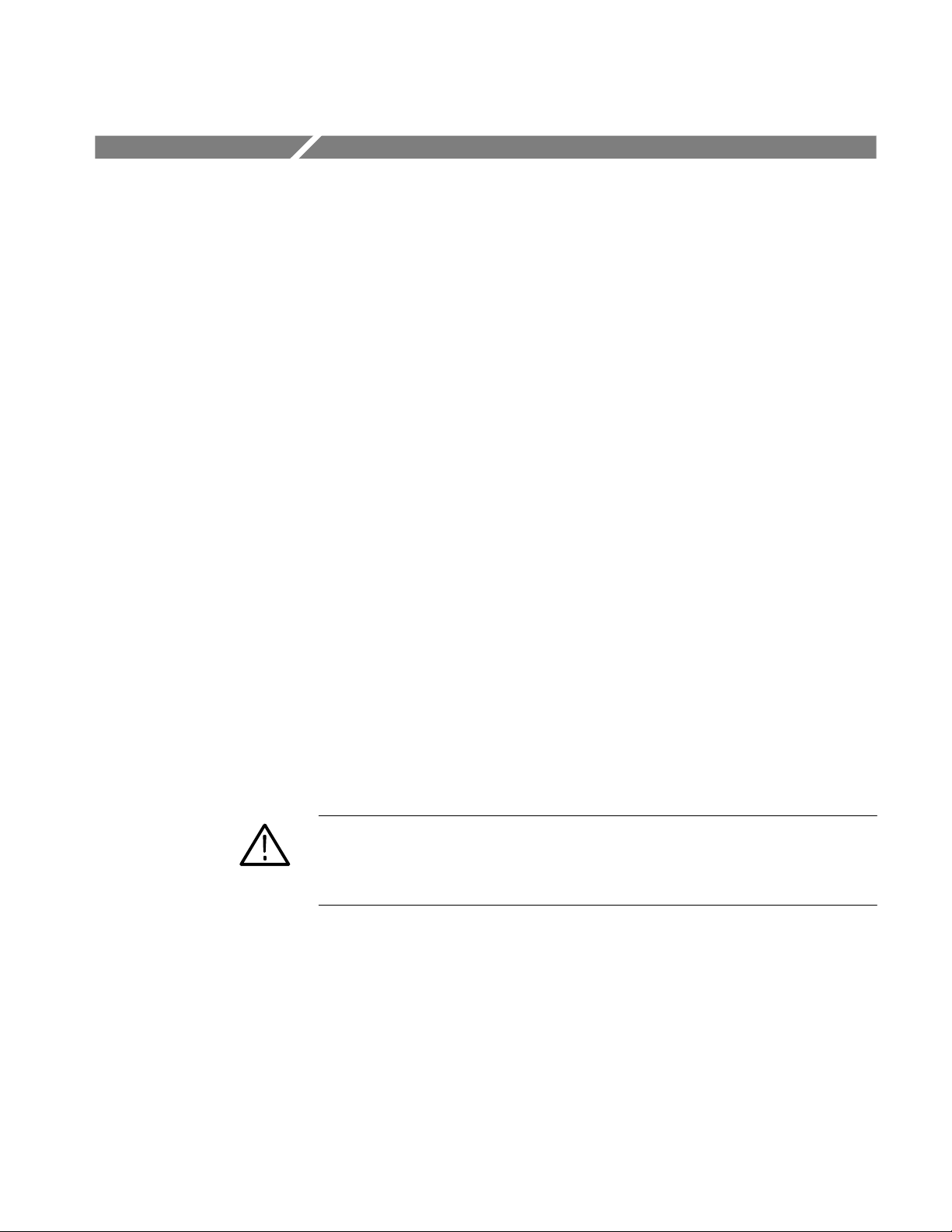
To determine if your measurement exceeds the Ampere-second product, perform
either Procedure A or Procedure B:
Procedure A
4
To determine the maximum allowable pulse width, measure the peak current of
the pulse (see Figure 3a). Divide the Ampere-second (or Ampere-microsecond)
specification of your probe by the measured peak current of the pulse. The
quotient is the maximum allowable pulse width; the pulse width at the 50% point
of the measured signal must be less than this value.
A6303 & A6303XL Instructions
Page 15
Getting Started
I
max
p
Pulse width
at 50%
50%
I
max
c
0A
(a) Maximum allowable pulse width (b) Maximum allowable pulse amplitude
Figure 3: Applying the Amp-second product rule
Do not exceed
Maximum
pulsed
current
Pulse width
at 50%
50%
Maximum
continuous
current
Procedure B
To determine the maximum allowable pulse amplitude, measure the pulse width
at the 50% points (see Figure 3b). Divide the Ampere-second (or Amperemicrosecond) specification of your probe by the pulse width. The quotient is the
maximum allowable current; the peak amplitude of the measured pulse must be
less than this value.
A6303 & A6303XL Instructions
5
Page 16
Specifications
Mechanical, electrical, and environmental characteristics unique to the probe are
listed in this section. The probe’s performance specifications are determined by
the amplifier that it is used with. Please refer to the amplifier documentation for
probe performance specifications.
Table 1: Electrical Characteristics
Bandwidth (--3 dB) A6303: DC to 15 MHz
A6303XL: DC to 10 MHz
Rise Time (10% to 90%) A6303: ≤23 ns
A6303XL: ≤35 ns
Frequency Derating 12 A at 10 MHz
Maximum Bare Wire Working Voltage 600 V
300 V
Maximum Continuous Current 100 A (DC + peak AC)
Maximum Pulsed Current 500 A
Amp⋅Second Product 1 ¢ 10-2A⋅s (10,000 A⋅s)
Insertion Impedance 0.02 Ω at 1 MHz
0.15 Ω at 15 MHz
RMS
RMS
,CATII
, CAT III
6
A6303 & A6303XL Instructions
Page 17
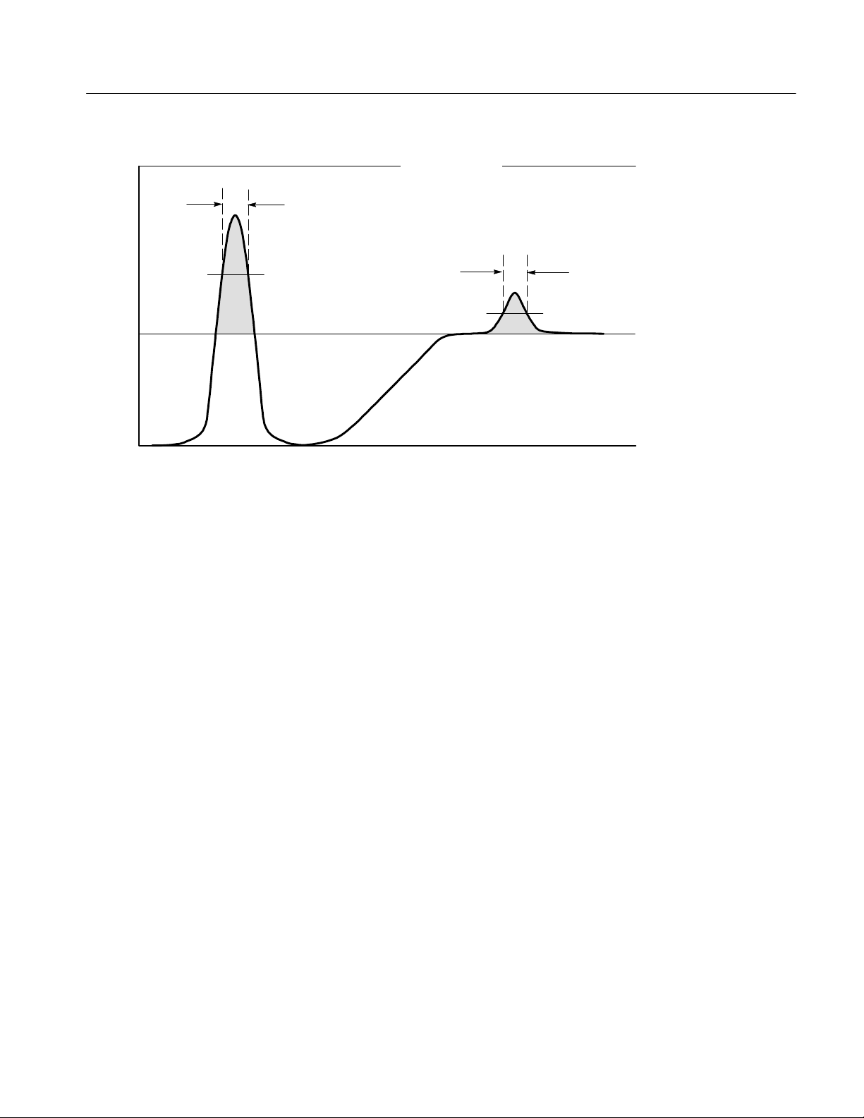
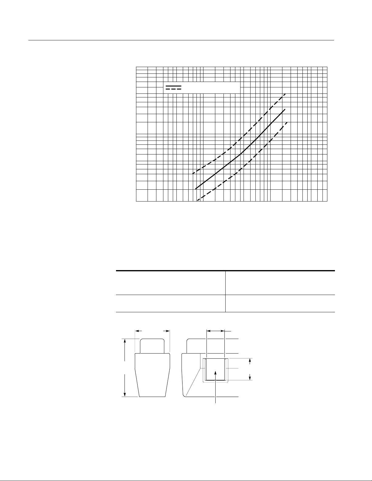
Specifications
500
400
Amp-second product limit = 10,000 A ⋅ s
Max. peak pulse (≤500 A)
300
200
Amperes (peak)
Max. continuous pulse
100
10
40
50
60
3020
8070
90
(≤100 A)
100
Allowable pulse width (microseconds)
Figure 4: A6303 and A6303XL specified operating area
Any width
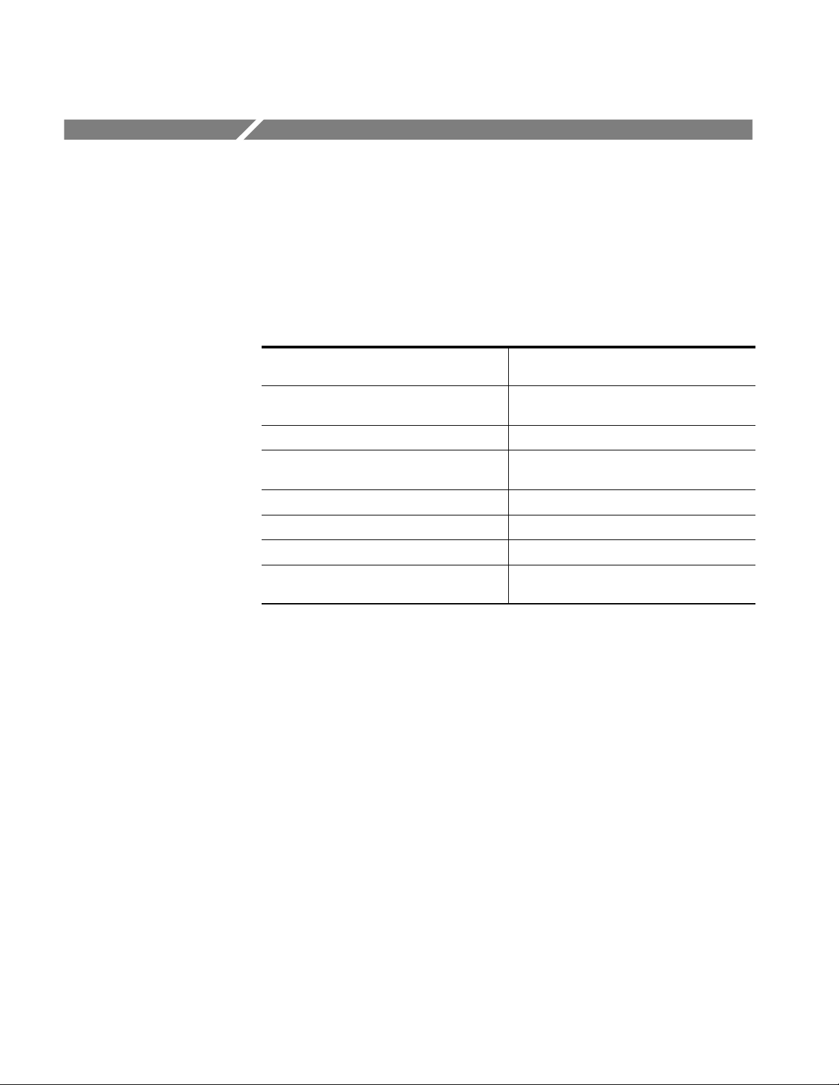
200
100
50
10
Maximum input current (Amperes peak)
1
0.001
0.01
Frequency (MHz)
Figure 5: A6303 and A6303XL frequency derating curve
Derating curve
Maximum input current
501010.1
A6303 & A6303XL Instructions
7
Page 18
Specifications
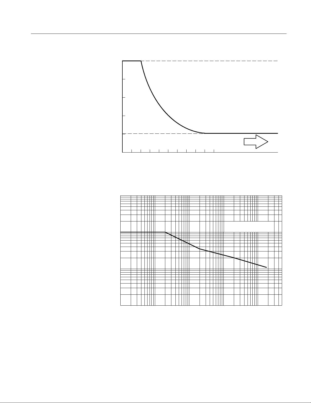
1.0
0.5
0.2
0.1
.05
Typical impedance
Impedance deviation
Insertion impedance (ohms)
.02
.01
0.1
0.2
Frequency (MHz)
Figure 6: A6303 and A6303XL insertion impedance curve
105210.5
5020
Table 2: Mechanical Characteristics
Probe Dimensions Length: 26.8 cm (10.6 inches)
Width: 4.05 cm (1.6 inches)
Height: 15.6 cm (6.13 inches)
Cable Length A6303: 2 m (6.6 feet)
A6303XL: 8 m (26.25 feet)
21 mm
(0.83 in)
25 mm
(1.0 in)
67 mm
(2.7 in)
41 mm
(1.6 in)
Maximum Wire Size
21 mm (0.83 in)
Figure 7: A6303 and A6303XL Probe Jaw Dimensions (Nominal)
8
A6303 & A6303XL Instructions
Page 19

Table 3: Environmental Characteristics
Operating Temperature 0°Cto50°C
Storage Temperature -- 4 0 °Cto75°C
Humidity
Specifications
Nonoperating
Operating
Altitude
Operating
Transportation Qualifies under National Safe Transit
Mechanical Shock 500 g. Half sine. Three shocks on three of the
Vibration 0.025 in. pk-pk displacement. 10 -- 50 Hz in
Random Vibration
Operating
30°Cto60°Cat90to95%RH
30°Cto50°Cat90to95%RH
2,000 m (6,416 ft)
Procedure 1A, category II, 36 i n. drop.
probe for 1 ms duration. Total of 9 shocks.
1min. cycles. Hold 9 min. at any major
resonance, or if none, at 55 Hz. Total time, 54
min.
0.31 g
axis.
Tektronix Std. 062-2858-00, Rev. B, Class 3.
, 5 to 500 Hz, 10 minutes on each
RMS
A6303 & A6303XL Instructions
9
Page 20

Specifications
Table 4: Certifications and Compliances
EC Declaration of Conformity -Low Voltage
Approvals UL3111-1 -- Standard for electrical measuring and test equipment
Installation Category Descriptions Terminals on this product may have different installation category designations. The installation
Compliance was demonstrated to the fol lowing specification as listed in the Official Journal of the
European Communities:
Low Voltage Directive 73/23/EEC
EN 61010-1:1993 Safety requirements for elect ric al equipment for measurement,
control, and laboratory use
EN 61010-2-032:1995 Particular requirements for hand-held current clamps for electrical
measurements and test
CAN/CSA C22.2 No. 1010.1 -- Safety requirements for electrical equipment for measurement,
control and laboratory use
IEC1010-2-032 -- Safety requirements for electrical equipment for measurement, control, and
laboratory use
categories are:
CAT III Distribution-level mains (usually permanently connected). Equipment at this l evel is
typically in a fixed industrial location
CAT II Local-level mains (wall sockets). Equipment at this level includes appliances, portable
tools, and similar products. Equipment is usually cord-connected
CAT I Secondary (signal level) or battery operated circuits of electronic equipment
10
A6303 & A6303XL Instructions
Page 21
Maintenance
Cleaning
This section explains how to clean the A6303 & A6303XL current probes and, if
necessary, disassemble a probe for maintenance or repair. Also included are
instructions for preparing a probe for shipment.
The A6303 & A6303XL current probes should require only routine cleaning.
Performance verification and probe adjustment procedures may be found in the
AM 503B & AM 5030 Instruction Manual.
WARNING. Probe disassembly should only be performed by qualified service
personnel.
To clean the probe body, use a soft cloth dampened in a solution of mild
detergent and water. To clean the core, open the jaw and clean the exposed core
surfaces with a cotton swap dampened with isopropyl alcohol (isopropanol) or
ethyl alcohol (fotocol or ethanol).
Do not lubricate the mating surfaces of the jaws. Any lubricant between the core
pieces should be removed with a recommended solvent.
Do not use chemicals containing benzine, benzene, toluene, xylene, acetone, or
similar solvents.
Do not use a petroleum based lubricant on the plastic. If the plastic slide
assembly requires lubrication, use a silicone based grease sparingly.
Do not immerse the probe in liquids or use abrasive cleaners.
Disassembly Instructions
The following procedures explain how to disassemble the probe body and
replace the current transformer.
WARNING. Probe disassembly should only be performed by qualified service
personnel.
1. Unlock the probe slide.
A6303 & A6303XL Instructions
11
Page 22

Maintenance
2. Place the probe on a flat surface with the screw heads facing up.
3
3. Using a
/32inch Allen wrench, remove the eight retaining screws from the
case.
4. While holding the squeeze handle and slide, lift the top part of the probe
body off.
5. Remove the slide.
WARNING. There is a spring in the squeeze handle that can pop out and cause
personal injury unless care is exercised when disassembling the probe.
6. Lift the cable out of the probe handle and insert a pair of pliers in the handle
as shown in Figure 8.
Torsion spring
Body half
Squeeze
handle
Figure 8: Removing the handle
7. While maintaining a firm grip on the pliers, carefully lift the squeeze handle
and gear out of the probe. See Figure 8.
8. To remove the current transformer, lift the assembly out of the probe as
shown in Figure 9 and unplug it from the circuit board.
12
A6303 & A6303XL Instructions
Page 23

Current transformer
Maintenance
Circuit board
Figure 9: Removing the current transformer
9. To remove the circuit board, unplug the board from the current transformer.
10. Before reassembling the probe, be sure that the gap between the stationary
and moveable core pieces is clean. If necessary, use isopropyl alcohol or a
similar cleaning agent to clean the pieces. Also, clean the contacts of the
slide switch, if necessary. Should the plastic slide assembly require
lubrication, sparingly apply silicone-based grease to the parts.
Probe reassembly is the reverse of steps 1 through 9. You may need to
squeeze the handle slightly to align the gear teeth with the slide rack.
NOTE. Exercise care when fitting the slide back into the probe body; aligning the
switch contacts can require patience.
Obtaining Replacement Parts
Replacement parts may be obtained through your local Tektronix field office or
representative. Refer to the Replaceable Parts List on page 15 for more
information.
A6303 & A6303XL Instructions
13
Page 24

Maintenance
Preparation for Shipment
If you must ship your Tektronix product, please use the original packaging if
possible. If the original packaging is unfit for use or not available, use the
following packaging guidelines:
1. Use a corrugated cardboard shipping carton having inside dimensions at least
2. Put the probe into a plastic bag or wrap to protect it from dampness.
3. Place the probe into the box and stabilize it with light packing material.
4. Seal the carton with shipping tape.
one inch greater than the probe dimensions. The box should have a carton
test strength of at least 200 pounds.
14
A6303 & A6303XL Instructions
Page 25

Replaceable Parts List
This section contains a list of the components that are replaceable for the Current
Probe. As described below, use these lists to identify and order replacement
parts.
Parts Ordering Information
Replacement parts are available from or through your local Tektronix, Inc.,
service center or representative.
Changes to Tektronix instruments are sometimes made to accommodate
improved components as they become available and to give you the benefit of
the latest circuit improvements. Therefore, when ordering parts, it is important to
include the following information in your order:
H Part number
H Instrument type or model number
H Instrument serial number
H Instrument modification number, if applicable
If a part you order has been replaced with a different or improved part, your local
Tektronix service center or representative will contact you concerning any
change in the part number.
Using the Replaceable Parts List
The tabular information in the Replaceable Parts List is arranged for quick
retrieval. Understanding the structure and features of the list will help you find
all the information you need for ordering replacement parts.
Item Names
Abbreviations
In the Replaceable Parts List, an Item Name is separated from the description by
a colon (:). Because of space limitations, an Item Name may sometimes appear
as incomplete. For further Item Name identification, U.S. Federal Cataloging
Handbook H6-1 can be used where possible.
Abbreviations conform to American National Standards Institute (ANSI)
standard Y1.1.
A6303 & A6303XL Instructions 15
Page 26
Replaceable Parts List
1
3
2
4
5
12
13
6
A1
10
11
8
9
7
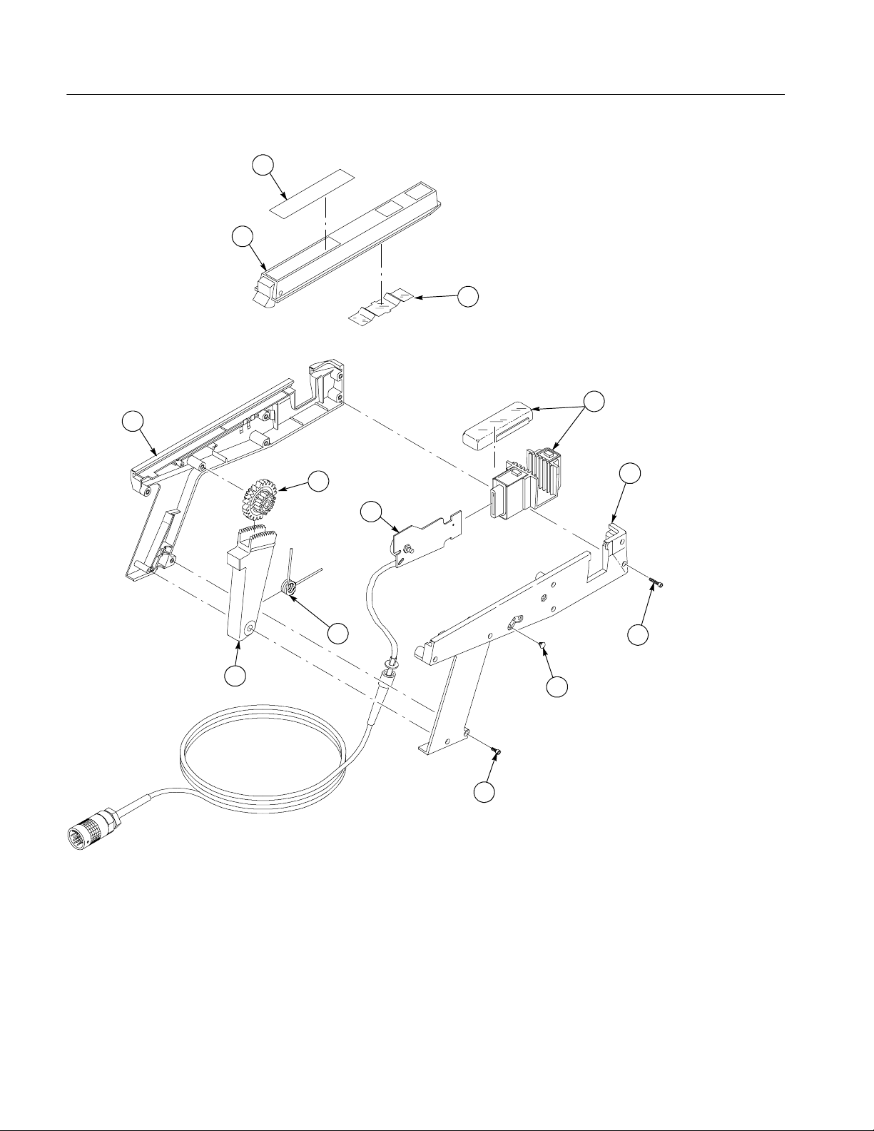
Figure 10: A6303 & A6303XL exploded view
16 A6303 & A6303XL Instructions
Page 27

Replaceable Parts List
Replaceable Parts List
Fig. &
index
number
10-- PROBE CURRENT:A6303/A6303XL
--1 204--0713--01 1 BODY HALF,PROBE:LEFT W/CONTACTS P6303 TK1163 ORDER BY DESCRIP
--2 351--0955--00 1 SLIDE ASSEMBLY:WITH WARNING LABEL 80009 351--0955--00
--3 334--4347--01 1 MARKER,IDENT:MKD A6303 07416 334-- 4347-- 01
--4 214--2422--00 1 SPRING,FLAT:UPPER CAN TK1326 214-- 2422-- 00
--5 120--1102--00 1 TRANSFORMER,CUR:TOP & BOTTOM 80009 120-- 1102--00
--6 204--0712--01 1 BODY HALF,PROBE:RIGHT W/CONTACTS P6303 TK1163 ORDER BY DESCRIP
--7 211-- 0093-- 00 6 SCREW,CAP:4-- 40 X 0.75,SCH,STL,CD PL,HEX REC 0KB01 ORDER BY DESCRIP
--8 348--0023--00 4 PLUG,HOLE:U/W0.14 DIA HOLE,WHT PLSTC 02768 207-- 090201-- 00-- 0101
--9 211-- 0183-- 00 2 SCREW,CAP:4-- 40 X 0.5,SCH,STL,CD PL,HEX REC 93907 ORDER BY DESCRIP
--10 174-- 3247-- 00 B031152 1 CABLE ASSY:CABLE ASSY W/CKT BD, A6303 80009 174--3247--00
--11 214-- 2446-- 00 1 SPR,HLCL,TRSN:0.1 OD X 0.5 L,MU SIC WIRE 8X345 ORDER BY DESCRIP
--12 367-- 0218-- 00 1 HANDLE,SQUEEZE:PROBE TK2565 367--0218-- 00
--13 401-- 0352-- 00 1 GR CLUSTER,SPUR:(2)18 AND (1) 24 T,PLASTIC TK2565 401-- 0352-- 00
Tektronix
part number
334--8622--01 1 MARKER,IDENT:MARKED A6303XL 0KB05 334--8622--01
174--3247--01 B031153 1 CABLE ASSY:W/C KT BD,A6303 80009 174-- 3247-- 01
174--3222--00 1 CABLE ASSEMBLY:WITH CIRCUIT BOARD,A6303XL 80009 174-- 3222-- 00
070--3906--XX 1 MANUAL,TECH:INSTRUCTION,A6303,A6303XL,DP TK2548 070--3906--XX
Serial no.
effective
Serial no.
discont’d
Qty Name & description Mfr. code Mfr. part number
Standard Accessories
A6303 & A6303XL Instructions 17
Page 28

Replaceable Parts List
Manufacturers Cross Index
Mfr.
code
02768 ILLINOIS TOOL WORKS INC 195 ALGONQUIN RD DES PLAINES, IL 60016--6103
07416 NELSON NAME PLATE COMPANY 3191 CASITAS AVENUE LOS ANGELES, CA 90039--2410
0KB01 STAUFFER SUPPLY CO 810 SE SHERMAN PORTLAND, OR 97214--4657
0KB05 NORTH STAR NAMEPLATE INC 5750 NE MOORE COURT HILLSBORO, OR 97124--6474
80009 TEKTRONIX INC 14150 SW KARL BRAUN DR
8X345 NORTHWEST SPRING MFG CO 5858 SW WILLOW LANE LAKE OSWEGO, OR 97035
93907 CAMCAR DIV OF TEXTRON INC ATTN: ALICIA SANFORD
TK1163 POLYCAST INC 9898 SW TIGARD ST TIGARD, OR 97223
TK1326 NORTHWEST FOURSLIDE INC 18500 SW TETON AVENUE TUALATIN, OR 97062
TK2548 XEROX CORPORATION DIV OF XEROX CORPORATION
TK2565 VISION PLASTICS INC 26000 SW PARKWAY CENTER DRIVE WILSONVILLE, OR 97070
Manufacturer Address City, state, zip code
PO BOX 500
516 18TH AVE
14181 SW MILLIKAN WAY
BEAVERTON, OR 97077--0001
ROCKFORD, IL 611045181
BEAVERTON, OR 97005
18 A6303 & A6303XL Instructions
 Loading...