

Page 1

80C12B
xx
ZZZ
Optical Sampling Module
User Manual
*P071299400*
071-2994-00
Page 2

Page 3

xx
80C12B
ZZZ
Optical Sampling Module
User Manual
www.tektronix.com
071-2994-00
Page 4

Copyright © Tektronix. All rights reserved. Licensed software products are owned by Tektronix or its subsidiaries
or suppliers, and are protected by national copyright laws and international treaty provisions.
Tektronix products are covered by U.S. and foreign patents, issued and pending. Information in this publication
supersedes that in all previously published material. Specifications and price change privileges reserved.
TEKTRONIX and TEK are registered trademarks of Tektronix, Inc.
Contacting Tektronix
Tektronix, Inc.
14150 SW Karl Braun Drive
P.O. Box 500
Beaverto
USA
For product information, sales, service, and technical support:
n, OR 97077
In North America, call 1-800-833-9200.
Worl dwid e, visi t www.tektronix.com to find contacts in your area.
Page 5

Warranty
Tektronix warrants that this product will be free from defects in materials and workmanship for a period of three
(3) years from the date of shipment. If any such product proves defective during this warranty period, Tektronix, at
its option, either will repair the defective product without charge for parts and labor, or will provide a replacement
in exchange for the defective product. Parts, modules and replacement products used by Tektronix for warranty
work may be n
the property of Tektronix.
ew or reconditioned to like new performance. All replaced parts, modules and products become
In order to o
the warranty period and make suitable arrangements for the performance of service. Customer shall be responsible
for packaging and shipping the defective product to the service center designated by Tektronix, with shipping
charges prepaid. Tektronix shall pay for the return of the product to Customer if the shipment is to a location within
the country in which the Tektronix service center is located. Customer shall be responsible for paying all shipping
charges, duties, taxes, and any other charges for products returned to any other locations.
This warranty shall not apply to any defect, failure or damage caused by improper use or improper or inadequate
maintenance and care. Tektronix shall not be obligated to furnish service under this warranty a) to repair damage
result
b) to repair damage resulting from improper use or connection t o incompatible equipment; c) to repair any damage
or malfunction caused by the use of non-Tektronix supplies; or d) to service a product that has been modified or
integrated with other products when the effect of such modification or integration increases the time or difficulty
of servicing the product.
THIS WARRANTY IS GIVEN BY TEKTRONIX WITH RESPECT TO THE PRODUCT IN LIEU OF ANY
OTHER WARRANTIES, EXPRESS OR IMPLIED. TEKTRONIX AND ITS VENDORS DISCLAIM ANY
IMPLIED WARRANTIES OF MERCHANTABILITY OR FITNESS FOR A PARTICULAR PURPOSE.
TRONIX' RESPONSIBILITY TO REPAIR OR REPLACE DEFECTIVE PRODUCTS IS THE SOLE
TEK
AND EXCLUSIVE REMEDY PROVIDED TO THE CUSTOMER FOR BREACH OF THIS WARRANTY.
TEKTRONIX AND ITS VENDORS WILL NOT BE LIABLE FOR ANY INDIRECT, SPECIAL, INCIDENTAL,
OR CONSEQUENTIAL DAMAGES IRRESPECTIVE OF WHETHER TEKTRONIX OR THE VENDOR HAS
ADVANCE NOTICE OF THE POSSIBILITY OF SUCH DAMAGES.
[W4 – 15AUG04]
btain service under this warranty, Customer must notify Tektronix of the defect before the expiration of
ing from attempts by personnel other than Tektronix representatives to install, repair or service the product;
Page 6

Page 7

Table of Contents
General Safety Summary ......................................................................................... iv
Environmental Considerations ................................................................................... vi
Preface ............................................................................................................. vii
Specificati
Manual Structure............................................................................................. vii
Related Documentation ..................................................................................... viii
Getting Started ..... . ... . . ..... . ..... . ... . . . .... . ..... . ..... . ... . . ..... . ..... . ... . . . .... . ..... . ..... . ... . . ..... . ..... 1
Instrument Requirements .................. ................................ ................................ ... 1
Module Features ............................................................................................... 1
Options
Installation ............................. ................................ .................................. ....... 6
Operating Basics.................................................................................................... 9
Usage....................... ................................ .................................. ................... 9
System Interaction............................................................................................ 10
Front Panel Controls............................ ................................ .............................. 11
Comm
Programmer Interface Commands .............................. ................................ ............ 14
User Adjustments ............................... ................................ .............................. 14
Optimizing Measurement Accuracy .............................. .................................. ........ 14
Cleaning ....................................................................................................... 18
Reference ............... .................................. ................................ .......................... 21
velength, Filter, and Bandwidth Selection . . ..... . ... . . ..... . ..... . ..... . ..... . .... . . .... . ..... . ..... . . 21
Wa
Clock Recovery ........................... ................................ .................................. .. 21
Electrical versus Optical Bandwidth........................................................................ 21
Glossary
Index
ons................................................................................................. vii
and Accessories ...................................................................................... 3
ands from the Main Instrument Front Panel ....................................................... 12
80C12B Optical Sampling Module User Manual i
Page 8

Table of Contents
List of Figure
Figure 1: Module compartments.................................................................................. 7
Figure 2: Co
Figure 3: 80C12B optical module front panel.................................................................. 11
Figure 4: Vertical Setup dialog boxes (DSA8300)............................................................. 13
nnecting optical cables correctly............ ................................ ....................... 9
s
ii 80C12B Optical Sampling Module User Manual
Page 9

List of Tables
Table 1: 80C12B module features ................... .................................. ........................... 2
Table 2 : St a
Table 3: Available 80C12B filter options ........................................................................ 3
Table 4: Available 80C12B calibration and warranty options ............................ ..................... 4
Table 5: Optional accessories ..................................................................................... 5
ndard accessories ..................................................................................... 3
Table of Contents
80C12B Optical Sampling Module User Manual iii
Page 10

General Safety Summary
General Safet
To Avoid Fire or Personal
Injury
ySummary
Review the fo
this product or any products connected to it.
To avoid pot
Only qualified personnel should perform service procedures.
While using this product, you may need to access other parts of a larger system.
Read the safety sections of the other component manuals for warnings and
cautions r
Ground the product. This product is indirectly grounded through the grounding
conductor of the mainframe power cord. To avoid electric shock, the grounding
conductor must be connected to earth ground. Before making connections to
the input or output terminals of the product, ensure that the product is properly
ground
Observe all terminal ratings. To avoid fire or shock hazard, observe all ratings
and ma
information before making connections to the product.
The i
ed.
nputs are not rated for connection to mains or Category II, III, or IV circuits.
llowing safety precautions to avoid injury and prevent damage to
ential hazards, use this product only as specified.
elated to operating the system.
rkings on the product. Consult the product manual for further ratings
Do not apply a potential to any terminal, including the common terminal, that
eeds the maximum ratingofthatterminal.
exc
Do not operate without covers. Do not operate this product with covers or panels
oved.
rem
Do not operate with suspected failures. If you suspect that there is damage to this
oduct, have it inspected by qualified service personnel.
pr
Avoid exposed circuitry. Do not touch exposed connections and components when
ower is present.
p
Wear eye protection. Wear eye protection if exposure to high-intensity rays or
laser radiation exists.
Do not operate in wet/damp conditions.
Do not operate in an explosive atmosphere.
Keep product surfaces clean and dry.
Provide proper ventilation. Refer to the manual's installation instructions for details
on installing the product so it has proper ventilation.
iv 80C12B Optical Sampling Module User Manual
Page 11
General Safety Summary
TermsinThisManual
Symbols and Terms on the
Product
These terms may
WAR NI NG . Warning statements identify conditions or practices that could result
in injury or loss of life.
CAUTION. Caution statements identify conditions or practices that could result in
damage to this product or other property.
These terms may appear on the product:
DANGER in
the marking.
WARNING
read the marking.
CAUTIO
The following symbol(s) may appear on the product:
appear in this manual:
dicates an injury hazard immediately accessible as you read
indicates an injury hazard not immediately accessible as you
N indicates a hazard to property including the product.
80C12B Optical Sampling Module User Manual v
Page 12

Environmental Considerations
Environmenta
Product End-of-Life
Handling
Restriction of Hazardous
Substances
l Considerations
This section
Observe the following guidelines when recycling an instrument or component:
Equipment Recycling. Production of this equipment required the extraction and
use of natu
harmful to the environment or human health if improperly handled at the product’s
end of life. In order to avoid release of such substances into the environment and
to reduce the use of natural resources, we encourage you to recycle this product
in an appropriate system that will ensure that most of the materials are reused or
recycled appropriately.
This product has been classified as Monitoring and Control equipment, and is
outside the scope of the 2002/95/EC RoHS Directive.
provides information about the environmental impact of the product.
ral resources. The equipment may contain substances that could be
This symbol indicates that this product complies with the applicable European
Union requirements according to Directives 2002/96/E C and 2006/66/EC
on waste electrical and electronic equipment (WEEE) and batteries. For
information about recycling options, check the Support/Service section of the
Tektronix Web site (www.tektronix.com).
vi 80C12B Optical Sampling Module User Manual
Page 13

Preface
This manual includes the following information:
The capabilities of the module
How to install the module
How to control signal acquisition, processing, and input/output of information
Specifications
The latest
site (www.tek.com/manuals).
Specifications are located in the specifications and performance verification
document for your main instrument. You can download the manual from the
Tektronix Web site (www.tek.com/manuals).
To meet measurement specifications, ensure that:
version of this document is available at the Tektronix manuals Web
The instrument was calibrated/adjusted at an ambient temperature between
+20 °C and +30 °C.
The instrument has been operating continuously for 20 minutes within the
operating temperature range specified.
Vertical compensation has been performed with the module installed in the
same compartment used when the compensation was performed. Ambient
temperature must be within ± 2 °C of the compensation temperature.
The instrument must be in an environment with temperature, altitude,
humidity, and vibration within the operating limits described in the
specifications.
nual Structure
Ma
This manual contains the following chapters:
Getting Started shows you how to configure and install your optical module.
Operating Basics describes controlling the module using the front panel and
the instrument user interface.
Reference provides information on wavelength selection, clock recovery,
and optical bandwidth.
80C12B Optical Sampling Module User Manual vii
Page 14

Preface
Related Documentation
This document covers installation and usage of the sampling module and its
features. For information about the main instrument in which the sampling
module is installed, refer to the user documents and online help provided with
your main instrument.
viii 80C12B Optical Sampling Module User Manual
Page 15

Getting Started
The 80C12B Series Optical Sampling Module is a high-performance optical
module that supports high bandwidth telecom and datacom standards from
155 Mb/s to 11
compatible with the following main instruments (mainframes):
.7 Gb/s in a single optical sampling module. The module is
Instrument Requirements
DSA8300
DSA8200, CSA8200,
CSA8000B, CSA8000,
TDS8200, TDS8000B, and
TDS8000
DSA8300 Dig
DSA8200 Digital Serial Analyzer
CSA8000, CSA8000B, and CSA8200 Communications Signal Analyzers
TDS8000, TDS8000B, and TDS8200 Digital Sampling Oscilloscopes
TekScope application software version 6.0.3.X or greater.
Select Help > About from the TekScope application Help menu to show
your current version.
Microsoft Windows 7 Ultimate (32 bit) operating system.
cope application software version 5.1 or greater.
TekS
Select Help > About from the TekScope application Help menu to show
current version.
your
Microsoft Windows XP operating system.
ital Serial Analyzer
Contact Tektronix Customer Support (www.tek.com) for information on how to
upgrade your instrument to meet these requirements.
Module Features
Table 1 lists the 80C12B optical module features. (See Table 1 on page 2.)
The Operating Basics section has information on the module controls, connectors,
and indicators. (See Figure 3 on page 11.)
80C12B Optical Sampling Module User Manual 1
Page 16

Getting Started
Table 1: 80C12B
Feature Description
Number of inpu
Effective wa
Calibrated
Supported s
wavelength settings
module features
t channels
velength range
tandards or data
1
1
700 nm to 1650 nm
850 nm, 1310 nm, 1550 nm
(See Table 3
on page 3.)
filtering rates
Typical op
tical bandwidth at
>12 GHz (available with Options F0, 10G, or 10GP)
optical connector
Clock recovery Connect the BUFFERED electrical outputs to a CR175A
or CR286A Clock Recovery instrument (purchased
ly). (See page 21, Clock Recovery.)
age power (850 nm)
Absolute maximum
ructive optical input
nondest
separate
4mWaver
2
2 mW average power (1310 nm, 1550 nm)
10 mW peak power for 60 ms.
Internal fiber diameter 62.5 μm/125 μm multimode fiber
3
Optical return loss >14 dB for multimode fiber
for single-mode fiber
>24 dB
Outpu
tzero
mmediately after dark calibration ±2% × (vertical
<1 μWi
offset)
pendent channel deskew
Inde
Offset capability at front of
Standard
Standard
module
Power meter
1
Some values in the table are typical. See the product data sheet or the DSA8300 Specifications and Performance
Verification Technical Reference for more information.
2
Optical input powers below maximum nondestructive levels may exceed module input saturation and compression
limits.
3
Compatible with single-mode fiber of equal or smaller diameter.
Standard
2 80C12B O ptical Sampling Module User Manual
Page 17

Getting Started
Options and Ac
Standard Accessories
Options
cessories
This section lists the standard and optional accessories available for the sampling
modules.
The following acc essories are shipped with the module:
Table 2: Standard accessories
Item Part number
80C12B Optical Sampling Module User
Manual (this document)
Certificate of Traceable Calibration for
product at first shipment
SMA male 50 Ω termination (installed,
one per buffered electrical signal output
connector)
Fiber cleaning kit 020-2494-XX
80C12B. The standard 80C12B module provides user-selected filter options for
measuring specified sets of standards. There are three module configurations
available:
071-2994-XX
Not orderable
015-1022-XX
Option 10G provides Optical Reference Receiver (ORR) filters for all
standard rates between 8.5 and 11.7 Gb/s.
Options F0 - F12 provide 4 "tributary" filters for standards at data rates
from 155 Mb/s to 7.373 Gb/s. Select the four filter options when ordering
the module. (See Table 3.)
Option 10GP plus any three F1–F12 filters provides Optical Reference
Receiver (ORR) filters for all standard rates between 8.5 Gb/s and 11.7 Gb/s
plus the three selected tributary standard rates. (See Ta ble 3.)
NOTE. Options 10GP and F0 are mutually exclusive, as Option 10GP already
includes Option F0.
Available 80C12B filter options are:
Table 3: Available 80C12B filter options
Option Description
F0
F1
F2
Unfiltered 12 GHz bandwidth
OC-3/STM-1 (155.52 Mb/s)
OC-12/STM-4 (622 Mb/s)
80C12B Optical Sampling Module User Manual 3
Page 18

Getting Started
Table 3: Available 80C12B filter options (cont.)
Option Description
F3
F4
F5
F6
F7
F8
F9
F10
F11
F12
10GP FC8500 (8.500 Gb/s)
FC1063 (1.0625 Gb/s)
ENET1250 Gigabit Ethernet (1.250 Gb/s)
FC2125 (2.125 Gb/s)
OC-48/STM-16 (2.488 Gb/s)
2GBE (2.500 Gb/s)
INF2500 (2.500 Gb/s)
FEC2.666 Gb/s (2.666 Gb/s)
10GBASE-X4 (3.125 Gb/s)
10GFC-X4
FC-3188 (3.188 Gb/s)
FC4250 (4.250 Gb/s)
INF5000 (5.000 Gb/s)
OBSAI6144 (6.144 Gb/s)
CPRI7373 (7.373 Gb/s)
OC-192/STM-64 (9.95 Gb/s)
8GFC (8.500 Gb/s)
10GBASE-W (9.95 Gb/s)
10GBASE-R (10.31 Gb/s)
40GBASE-R4 (10.31 Gb/s)
100GBASE-R10 (10.31 Gb/s)
10GFC (10.51 Gb/s)
FEC10.66 (10.66 Gb/s)
FEC10.71 (10.71 Gb/s)
FEC11.10 (11.1 Gb/s)
FC11317 (11.3 Gb/s)
Unfiltered 12 GHz bandwidth
80C12B-10G. The 80C12B-10G module contains only the 10GP filters and
bandwidth.
Calibration and Warranty.
Table 4: Available 80C12B calibration and warranty options
Option Description
C3 Three years of calibration service
C5 Five years of calibration service
D1
D3
D5
R3 Extended repair warranty to three years
R5
Calibration data report
Three years of calibration data reports (requires Opt. C3)
Five years of calibration data reports (requires Opt. C3)
Extended repair warranty to five years
4 80C12B O ptical Sampling Module User Manual
Page 19

Getting Started
Optional Accessories
You can order th
e following accessories for use with the sampling modules. See
the Tektronix Web site for the current list of optional accessories:
Table 5: Optio
Item Part number
D4/PC Univer
Biconic UCI
FC/PC UCI ad
SMA 2.5 UCI
SC/PC UCI
DIN/PC UC
DIAMOND
SMA UCI
DIAMON
UCI adapter
ST/PC
le to 3.5 female SMA
3.5 ma
-on SMA connector
Slip
000 & TDS8000 Series Service Manual
CSA8
8300 Service Manual
DSA
DSA8200 Service Manual
DSA8300 S pecifications and Performance
Verification Technical Reference
80C12B Series Optical Sampling Module
ser Manual (this document)
U
nal accessories
sal Optical Input (UCI) adapter
adapter
apter, APC-108
adapter
adapter
I adapter
2.5 UCI adapter
adapter
D 3.5 UCI adapter
119-4514-XX
119-4515-XX
119-5115-XX
119-4517-XX
119-5116-XX
119-4546-XX
119-4556-XX
119-4557-XX
119-4558-XX
119-4513-XX
015-0552-XX
015-0553-XX
071-0438-XX
-0572-00 (PDF file downloadable from
077
the Tektronix Web site)
1-2049-XX
07
077-0571-00 (PDF file downloadable from
the Tektronix Web site)
071-2994-00
80C12B Optical Sampling Module User Manual 5
Page 20

Getting Started
Installation
Electrostatic Discharge
Cautions
CAUTION. The electrical data outputs on the optical module are subject to
damage from electrostatic discharge (ESD). To prevent damage from electrostatic
discharge,
Store the module, with the supplied SMA terminations installed, in a static-free
container
Whenever you move the optical module from one instrument to another, use a
static-f
Be sure to only operate the optical module in a static-controlled environment
(ground
Always use a grounded wrist strap (provided with your instrument) when
instal
observe the following guidelines:
, such as the shipping container.
ree container to carry the optical module.
ed conductive table top, wrist strap, floor mat, and ionized air blower).
ling, removing, or handling an optical module or m aking connections.
Correct Module Handling
Guidelines
Discharge to ground any electrostatic charge on cables before attaching the cable
to the o
CAUT
Never install or remove a module when the instrument is powered on (front-panel
On/
Do not drop the module since damage and misalignment of the photodiode optical
as
Place the protective cap(s) on the optical and electrical input connectors when
th
To prevent loss of optical power or damage to the optical connectors, keep the
c
Check that all connectors, jumpers, and protective caps are clean before
connecting them to the module. (See page 18, Cleaning the Optical Connectors.)
ptical module.
ION. Take the following precautions to avoid damaging your optical module:
Standby power switch is ON).
sembly can result. Store the module in a secure location when not in use.
e module is not in use.
onnectors clean at all times.
6 80C12B O ptical Sampling Module User Manual
Page 21

Getting Started
Optical Sig nal
Module Locations
Overdrive
Caution
CAUTION. Circuitry in the optical module is very susceptible to damage from
overdriven s
levels for the module.
The optica
compartments support single channel modules, while the small compartments
support single or dual channel modules. Eight of the 10 inputs are usable at one
time. (See Figure 1.)
ignals. Verify that input optical signals are within acceptable power
l modules fit in the large upper module slots of the instrument. The large
Installing a Module
Figure 1: Module compartments
At least one module must be installed in an instrument to acquire signals.
NOTE. Installing a large module in either large compartment disables some of the
small compartment channels. Refer to the instrument Online Help for information
about compartment interaction.
1. Power off the instrument using the front-panel On/Standby power switch.
2. Plug the grounding strap into the instrument ground connector, and place the
ground strap on your wrist, with contact to skin.
3. Turn the hold-down screws all the way counterclockwise s o that they are
completely out and the module retaining tab is flush with the edge of the
module.
4. Insert the module into a compartment and slowly push it in with firm pressure
until it is seated.
80C12B Optical Sampling Module User Manual 7
Page 22

Getting Started
Removing a Module
5. Turn the hold-d
6. Once you have installed the module, power on the instrument. Verify that
the module pas
NOTE. When first installing a sampling module(s) or after moving a sampling
module from one compartment to another, run a module compensation (Utilities
> Compensation) to ensure that the instrument meets it specifications. You must
also run a compensation if an extender is installed, changed, or removed from a
module. (See page 14, Optimizing Measurement Accuracy.)
After running compensation, save the new values to retain them; otherwise they
are lost when powering off the instrument.
1. Power off the instrument using the front-panel On/Standby power switch.
2. Plug the grounding strap into the instrument ground connector, and place the
ground strap on your wrist, with contact to skin.
3. Turn the hold-down screws all the way counterclockwise so that they are
completely out and the module retaining tabs are flush with the edge of the
module.
4. Slide the appropriate large module ejector lever sideways to unseat the
module from the mainframe connector.
own screws clockwise to lock the module in place.
ses power-on tests.
5. Pull on the hold-down screws to remove the module from the slot.
6. Handle the module appropriately. For example, move it to another slot in the
instrument or place it in a static-protected environment for transport or storage.
8 80C12B O ptical Sampling Module User Manual
Page 23
Operating Basics
Usage
This section contains optical module signal connection and operation information.
Handle your optical module carefully at all times.
Connecting Optical Signals
Keep optical signal connectors clean to preserve the signal integrity. (See page 18,
Cleaning the Optical Connectors.)
The input of the 80C12B module can couple to any single-mode or multimode
dimension not exceeding a core diameter/cladding diameter of 62.5/125 μm. Use
UCI (universal connector interface) series adapters to couple alternate cable types
to the optical module. Refer to the Tektronix Web site for details.
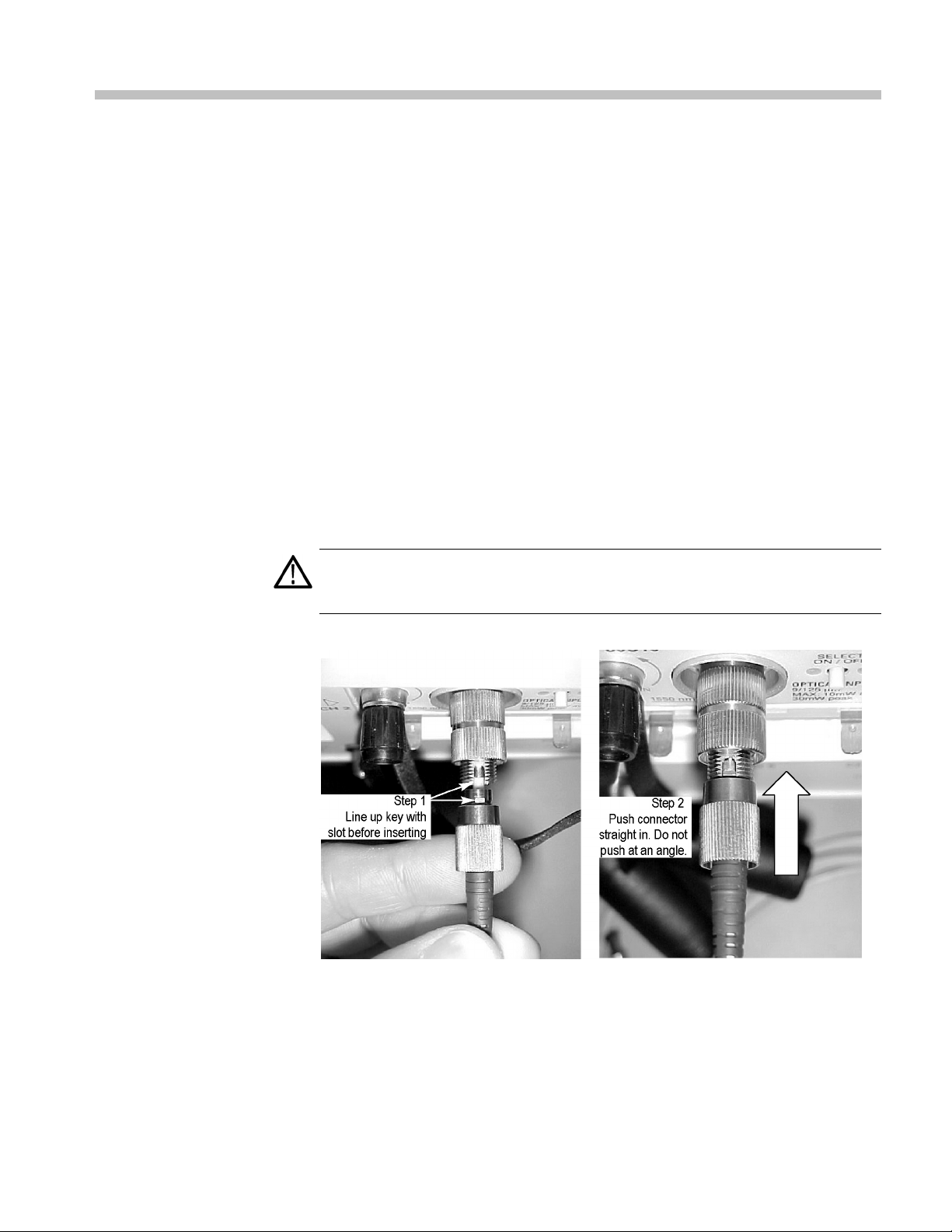
To connect the fiber optic cable to the module optical input:
1. Line up the key with the slot in the UCI adapter before inserting.
CAUTION. Do not insert the connector into the UCI adapter at an angle. Do
not insert the connector and then rotate to line up the key with the slot. Either
n can damage the UCI adapter.
actio
igure 2: Connecting optical cables correctly
F
2. Firmly push the cable connector or adapter into the interface ferrule until it
reaches the stop. Do not twist the cable while inserting.
80C12B Optical Sampling Module User Manual 9
Page 24

Operating Basics
Attenuating Optical
Signals
3. Firmly tighten
the cable connector or the adapter shell. Tighten with finger
pressure only.
4. To remove, loo
sen the cable connector or adapter shell and pull out without
rotating or bending the cable or adapter.
To keep the optical input power to an appropriate level, you may need to attenuate
the optical
signal. The 80C12B absolute maximum optical signal levels are:
4 mW average optical power at 850 nm
2 mW average optical power at 1310 nm and 1550 nm
10 mW peak at wavelength of highest responsivity
CAUTION. To avoid damaging the optical input of the module, attenuate the input
optical signal to the absolute maximum optical signal levels listed above.
NOTE. The 80C12B module can have a somewhat deteriorated response for
signals greater than 800 μW
al sampling modules can have dynamic ranges exceeded without obvious
Optic
(1310 nm and 1550 nm) and 1300 μW
p-p
(850 nm).
p-p
visual indication on the waveform because the overloaded signal output of the
photodetector may still be within the dynamic range of the internal electrical
sampler. To ensure accurate measurements, make sure that input signal levels are
within allowed ranges.
System Interaction
r optical module is a part of a larger instrument s ystem. Most optical module
You
functions are controlled automatically by the main instrument. These include such
things as vertical scaling and horizontal sampling rate. You do not directly control
these parameters; they are controlled for you as you perform tasks on the main
instrument. The parameters that you control from the optical module front panel
are explained in the Front Panel Controls section.
An additional optical module function that you control from the main instrument
is external channel attenuation. External Attenuation lets you enter a number
representing any external attenuation you have added to a channel.
10 80C12B Optical Sampling Module User Manual
Page 25

Operating Basics
Front Panel Co
Channel Selection
ntrols
The following figure shows the 80C12B front panel. (See Figure 3.)
Each channel has a SELECT channel button and an amber channel light. The
button operates as follows:
If the amber channel light is on, the channel is acquiring a waveform.
If you push the channel button and the channel is not being acquired (for
any channel or math waveform), then the instrument activates (turns on) the
channel.
If you push the button and the channel is active as a channel waveform, then
the instrument selects the channel waveform.
If the channel waveform is already selected when you push the channel
button, the instrument turns the channel off.
Figure 3: 80C12B optical module front panel
Optical Input Connector
80C12B Optical Sampling Module User Manual 11
The optical input connector uses a universal connector interface (UCI) that allows
use of many standard fi ber-optic female connector styles. Some of the standard
UCI interfaces supported are FC, ST, SC, and DIN.
Page 26

Operating Basics
Outputs
Hold-Down Screws
The 80C12B modu
recovery purposes, route this signal to the input of a Tektronix CR175A or
CR286A Electrical Clock Recovery instrument, or to an 80A05 Electrical Clock
Recovery module installed in the same mainframe.
CAUTION. Electrostatic discharge (ESD) will cause permanent damage to
electrical outputs. Adhere to standard ESD handling precautions when using
the outputs
or connectors to ground before attaching them to the BUFFERED outputs.
To discharge a cable, touch the center pin of the coaxial cable to a grounded
conductor (such as the outside ground conductor of the BUFFERED output
connector) just before connecting the cable to the module.
NOTE. Use 50 Ω terminations, provided with your optical module, on all unused
electrical outputs.
Hold-down screws attach the module to the main instrument. Once the hold-down
screws are loosened, use the module slot eject levers to remove the module from
a powered-down main instrument. Indicators on the hold-down screws point in
the direction that the latch is pointing.
. In particular, make sure to discharge all electrical signal cables
le provides buffered electrical signal outputs. For clock
. Do not pull on module connectors to remove a module; always use the
NOTE
hold-down screws to pull the module out far enough for you to hold the module
and remove it from the instrument.
mmands from the Main Instrument Front Panel
Co
The Vertical Setup dialog box (click Setup > Vertical from the instrument menu)
lets you toggle between the basic and optical module vertical setup controls.
SeeFigure4.)
(
Select the channel you want to set in the Waveform section of the dialog box.
Then select the Setup Wavelength, Filter, Bandwidth, or Compensate controls in
the dialog box to change those settings or to initiate a compensation. Optical
modules with the clock recovery option also have source and rate controls in
the Trigger dialog box.
12 80C12B Optical Sampling Module User Manual
Page 27

Operating Basics
Detailed infor
main instrument.
mation on these dialog boxes is found in the Online Help of your
Figure 4: Vertical Setup dialog boxes (DSA8300)
NOTE. The user interface (UI) images in this manual are from the DSA8300
ument. The DSA8200 UI, although different in appearance, has a similar UI
instr
layout as the DSA8300 for most functions.
80C12B Optical Sampling Module User Manual 13
Page 28

Operating Basics
Programmer In
terface Commands
The remote programming commands for all sampling modules are documented in
the Programmer Guide acce ssible from the instrument Help menu.
User Adjustments
All optical module setups, parameters, and adjustments are controlled by the
main instrument. To save, recall, or change any module settings, use the
main-instrument menus or front-panel controls. Consult the Online Help for
your main instrument.
Optimizing Measurement Accuracy
Performing the following procedures to increase (or maintain) the measurement
accuracy of the optical module:
Run Vertical Compensation
Clean the Optical Connectors
Run Dark-Level and User Wavelength Gain Compensations
Perform Vertical
Compensation
Performing a vertical compensation will maximize the accuracy of the automatic
measurements you take. This p rocedure uses internal routines to optimize the
vertical offset, gain, and linearity.
Overview To perform optical compensations Control elements and resources
Prerequisites
Access the
compensation
routines
1. Install the optical sampling module(s).
2. Place dust covers on all optical module channels (or
otherwise turn off optical inputs to the module).
3. Power on the instrument and allow a 20 minute
warm-up before doing this procedure.
4. Set the acquisition to run continuously.
5. Select Utilities > Compensation from the application
menu bar to open the Compensation dialog box.
The Compensation dialog box lists the main instrument
(mainframe) and installed sampling modules. The
temperature change from the last compensation is
also listed.
6. Wait until the Status for all items changes from Warm
Up to Pass, Fail,orComp Req'd.
See the instrument user documentation and
online help for details on operating the instrument
controls.
14 80C12B Optical Sampling Module User Manual
Page 29

Overview To perform optical compensations Control elements and resources
Set save
compensation
values
Select what to
compensate
Run
compensa
Verify t
compensation
routines pass
Compen
fail actions
tion
hat the
sation
7. Click Compensate and Save in the Select Action
area. Make sure to save the compensation values.
In-memory com
power off the instrument.
8. Select what to compensate
For DSA8300: You will need to run two compensations
to compensate the mainframe and all m odules. Select
Mainframe a
Modules and run the compensation.
For DSA8200: From the top pulldown list, choose All
(default selection) to compensate the main instrument
and all ins
9. Click Exe
10. Follow any on-screen instructions to disconnect
inputs and install terminations; be sure to follow static
precaut
11. The compensation may take several m inutes to
complet
main instrument and for all sampling modules listed
in the Compensation dialog box when compensation
tes.
comple
12. If Fail
appears as the Status, rerun the compensation.
If Fail status continues after rerunning compensation,
and the instrument has passed the 20-minute warm-up
d, the module or main instrument may need
perio
service. Contact Tektronix C ustomer Service.
pensation values are lost when you
nd run the compensation, then select All
talled modules.
cute to begin the compensation.
ions when following these instructions.
e. Verify that Pass appears as Status for the
Operating Basics
Perform Dark-Level and
User Wavelength Gain
Compensations
Performing a dark-level calibration m aximizes the accuracy of the extinction
ratio and other optical automatic measurements you take. Performing a User
Wavelength Gain compensation optimizes an optical channel for your custom
input signal. Use the following procedure to perform either compensation; this
cedure applies only to optical modules.
pro
NOTE. The user interface (UI) images in this manual are from the DSA8300
instrument. The DSA8200 UI, although different in appearance, has a similar UI
layout as the DSA8300 for most functions.
NOTE. These procedures compensate the selected module and its current
bandwidth or filter selection. The compensation values are not saved when
powering off the instrument.
80C12B Optical Sampling Module User Manual 15
Page 30

Operating Basics
Overview To perform optical compensations Control e lemen ts and resources
Prerequisite
Select the
waveform
s
1. Install the op
2. Use the Vert
Set the acquisition system to run continuously.
compensate.
tical sampling module in the instrument.
ical buttons to select the channel to
See the instrument user documentation and
online help f
controls.
or details on operating the instrument
Access the
dark-level
compensation
Run the
dark-level
compensation
3. Click Setup > Vertical.
4. Clic k the Dark Level button under Compensation.
Follow the on-screen instructions.
5. Repeat steps 2 through 4 for any additional optical
channels that you want to compensate.
If any of the following settings or conditions change after
performing a dark level compensation, run another dark
level compensation to maintain the measured accuracy.
Trigger rate setting
Vertical offset setting
Filter or bandwidth setting
Ambient temperature change of more than 1 °C
16 80C12B Optical Sampling Module User Manual
Page 31

Overview To perform optical compensations Control elem e nts and resources
Run the user
wavelength
gain
compensation
You can option
an optical channel:
NOTE. You must know the optical power value of the
custom signal
optical power meter to precisely measure and record the
custom optical signal power. Then connect the signal to the
module using
6. In the Vert Setup dialog box, click the User
Wavelength Gain button under Compensation. Follow
the on-scre
ally use a custom input signal to compensate
. Use an independently calibrated average
the sam e fiber cables.
en instructions.
Operating Basics
Set the wav
to be applied to the channel in the User Wavelength
Gain Compensation dialog box.
7. Click OK to
8. Repeat steps 2, 6, and 7 to compensate additional
optical channels.
elength and power values of the signal
execute the compensation.
80C12B Optical Sampling Module User Manual 17
Page 32

Operating Basics
Cleaning
Exterior
The case of the module keeps dust out and should not be opened. Confine cleaning
to the front panel of the module. To clean the case, remove the module from the
main instrum
of the module. (See page 6.)
WARNING. To prevent injury, power off the instrument and disconnect it from line
voltage before performing any cleaning.
Clean the exterior surfaces of the module with a dry lint-free cloth or a soft-bristle
brush. If any dirt remains, use a damp cloth or swab dipped in a 75% isopropyl
alcohol solution. Use a swab to clean narrow spaces around controls and
connectors. Do not allow moisture inside the module. Do not use abrasive
compou
CAUTION. To prevent damage, avoid the use of chemical cleaning agents which
might damage the plastics in this instrument. Use a 75% isopropyl alcohol
solution as a cleaner and wipe with deionized water. Use only deionized water
when cleaning the menu buttons or front-panel buttons. Before using any other
type of cleaner, consult your Tektronix Service Center or representative.
ent but first read the entire Installation procedure for proper handling
nds on any part of the chassis that may damage the chassis.
aning the Optic al
Cle
Connectors
Do not open the module case. There are no user serviceable components inside
the module and cleaning the interior is not required.
Small dust particles and oils can easily conta minate optical connectors and reduce
or block the signal. Take care to preserve the integrity of the connectors by
keeping them free of contamination.
AUTION. To prevent loss of optical power or damage to the optical connectors,
C
keep the connectors clean at all times.
To reduce the need for cleaning, immediately replace protective caps on the
optical connectors when not in use.
18 80C12B Optical Sampling Module User Manual
Page 33

Operating Basics
Overview To clean t
s
Supplie
required
Remove UCI
adapter
One comp
number 118-1068-01.
A cleaning tool, such as:
a FIS cassette cleaner, (such as FI-6270)
a FIS tape dispenser cleaner (such as FI-7111).
an Optipop pipe cleaner (such as F1-6364).
1. Loosen the UCI adapter and remove it. This exposes
the male fiber end-face behind the UCI connector.
Use the followi
ng items to clean optical connectors:
Dry, clean, and dust-free compressed air
Fiber cleaning cassette and/or tape dispenser cleaner
Pipe cleaner
CAUTION. Clean both ferrule endfaces with a dry cloth tape cleaner (cassetted
or in a dispenser).
For safe and effective cleaning of the optical male fiber end-face exposed after
removing the UCI adapter, Tektronix recommends the following method and tools.
he optical connectors
ressed air can, such as Tektronix part
Related i
Cleanin
the Tektronix Optical Connector Cleaner part
number 020-2494-XX) are available from several
supplie
nformation
g kits for optical connectors (such as
rs.
Clean UCI
pter
ada
2. Clean contaminates from the inside wall of the hollow
ale-to-female ferrule alignment tube inside the UCI
fem
adapter.
Use the compressed air can to clean the female
input of the UCI adapter end-to-end.
Pull the pipe cleaner through the UCI adapter.
UTION.
CA
input of the UCI adapter when it is installed on the module.
Do not blow compressed air into the female
80C12B Optical Sampling Module User Manual 19
Page 34

Operating Basics
Overview To clean the optical connectors Related information
Clean fiber
input
3. Advance the fiber cleaning cassette or tape-dispenser
cleaner to expose an unused clean section of the
lint-free, dr
4. Lightly drag the clean, dry, surface of the cleaning tool
cloth against the male end-face of the fiber input for a
short distan
5. Place the UCI adapter back on the cleaned fiber
end-face.
y, cleaning surface.
ce (a centimeter or two).
Dust cap
Clean
attaching
s
device
6. When the module does not have a fiber cable attached
to its inpu
airborne contaminates from lodging in the female
optical input.
7. Clean any male fiber end-face input fiber or device that
you a ttach to the UCI input.
t(s), attach the b lac k dust-cap to prevent
Use a similar cleaning method to clean the fiber
end-face input fiber or device.
20 80C12B Optical Sampling Module User Manual
Page 35

Reference
This section describes available filter selections, clock recovery enabling
procedures, and optical bandwidths.
Wave
length, Filter, and Bandwidth Selection
Clock Recovery
See Tables 1 and 3 for available wavelength, filter, and bandwidth information.
(See Table 1 on page 2.) (See Table 3 on p age 3.)
To select the optical wavelength, open the Vertical Setups menu. (See Figure 4
on page 13.)
Select the channel in the Waveform section of the menu. Then select the
wavelength of the signal to measure fromtheSetupWavelengthdropdownbox.
Use the Signal Conditioning boxes to select the filter and bandwidth appropriate
for your optical standard.
For more information, see the Online Help for your main instrument.
The 80C12B module comes standard with buffered electrical signal outputs.
Connect the buffered outputs to a CR175A or CR286A Clock Recovery module
to obtain a clock recovery signal. Refer to the CR175A or CR286A module user
documentation for triggering information.
When connecting cables to the BUFFERED outputs, make sure to torque the
connector to the proper value of 56 N/c (5 in-lb) ±2.8 N/c (0.25 in-lb)
Make sure to torque the SMA connector to the proper value when connecting
cables to the BUFFERED outputs:
56N•c(5in-lb)±2.8N•c(0.25in-lb)
Electrical versus Optical Bandwidth
Electrical bandwidth is defined as the frequency at which the power out is one half
the power out at a frequency near DC. In the voltage domain the power dissipated
into a resistive load (such as a 50 Ω termination
where V
the resistance value. The frequency dependent response of a system is typically
described using a logarithmic decibel scale. A value expressed in terms of a
decibelrelativetoareferenceisdefined as:
80C12B Optical Sampling Module User Manual 21
is the RMS of the voltage swing seen at the resistive load, and R is
RMS
of a sampler) is the V
RMS
2
/R
Page 36

Reference
For electrical
the system to a sinusoidal frequency at or near DC. The point at which the system
response (power) is at one half would therefore be:
In terms of frequency, voltage, and resistance the bandwidth is expressed as:
where V(f) is the RMS of the voltage swing response at the bandwidth frequency,
and V(DC) is the RMS voltage swing response at a frequency approaching DC.
Further math yields V(f) = 0.707 V(DC).
The expression is simplified by canceling the R and moving the squared term
inside the log expression to a multiple outside the log expression:
In the DSA8300, DSA8200, CSA8000 and TDS8000 Series instruments, the
vertical units displayed for an optical module are not in volts, but in watts, which
are units of power. The optical-to-electrical converter inside the module outputs
a voltage the amplitude of which is linearly dependent on the incoming optical
power; in this condition the voltage applied at the electrical sampler already
represents optical power in i
voltage and divide by R).
bandwidths the reference of a system is commonly the response of
ts linear form (as opposed to having to square the
For the optical sampling mod
power is one half that approaching DC is:
The V(f) is the frequency at which the vertical swing is one half (0.5) the V(DC)
(not 0.707). The optical bandwidth therefore corresponds to the electrical
bandwidth of -6 dB.
During impulse testing of optical modules, the resulting impulse waveform is
converted to a frequency by Fo
as –3 dB = 10 log(vertical swing at frequency/vertical swing at DC). During
reference receiver curve calculation, however, the definition is changed to match
the industry standard definition which assumes electrical bandwidths are –3 dB =
20 log(vertical swing at frequency/vertical swing at DC).
ules, the bandwidth where the displayed optical
urier transform and the bandwidth is d efined
22 80C12B Optical Sampling Module User Manual
Page 37

Reference
Bandwidth for Unfiltered
Frequency Settings
Bandwidth for Reference
Receiver Settings
The curve calcu
(for example, 2 GHz, 2.5 GHz, 21 GHz, 12.5 GHz, 14 GHz, 20 GHz, 30 GHz,
40 GHz, 50 GHz, 65 GHz, and 80 GHz) uses the definition for dB and optical
bandwidth:
–3 dB = 10 log(vertical swing at frequency / ve rtical swing at DC)
The curve ca
GbE, Infiniband, and OC/STM standards) uses the definition of dB and bandwidth
that matches the industry standard which assumes electrical bandwidths:
–3 dB = 20 log(vertical swing at frequency/vertical swing at DC)
lation of frequency response for the unfiltered frequency settings
lculation of frequency response for reference receiver settings (FC,
80C12B Optical Sampling Module User Manual 23
Page 38

Reference
24 80C12B Optical Sampling Module User Manual
Page 39

Glossary
Accuracy
The closeness of the indicated value to the true value.
Analog-to-Digital Converter
A device that converts an analog signal to a digital signal.
Attenuation
A decrease in magnitude (for optical systems this is u sually optical power)
of a signal.
Autoset
A means of letting the instrument set itself to provide a stable and meaningful
display of a given waveform.
Average Optical Power (AOP)
The time averaged m easurement of the optical power over a much longer time
period than the bit rate of the s ignal.
Bandwidth
The difference between the limiting frequencies of a continuous frequency
spectrum. Bandwidth is the frequency at which the power out is one half
the power out at a frequency near DC. The range of frequencies handled by
adeviceorsystem. Bandwidthisameasure of network capacity. Analog
bandwidth is measured in cycles per second. Digital
in bits of information per second. (See page 21, Electrical versus Optical
Bandwidth.)
Channel
A place to connect a signal or attach a network or transmission line to
sampling heads. Also, the smallest component of a math expression. A
transmission path between two or more stations.
Channel Number
The number assigned to a specific signal input connector. The top channel of
the left-most sampling head compartment of the main instrument is always
channel 1, regardless of any repositioning or omission of sampling heads.
Clock
bandwidth is measured
A signal that provides a timing reference.
80C12B Optical Sampling Module User Manual 25
Page 40

Glossary
Common Mode
A circumstance where a signal is induced in phase on both sides of a
differential
network.
dB
Decibel: a method of expressing power or voltage ratios. The decibel scale is
logarithmic. It is often used to express the efficiency of power distribution
systems when the ratio consists of the energy put into the system divided by
the energy delivered (or in some cases, lost) by the system. One milliwatt of
optical po
wer is usually the optical reference for 0 dBm. The formula for
decibels is:
where Viis the voltage of the incident pulse, Vlis the voltage reflected
back by the load, P
is the power out, and Piis the power in. (See page 21,
o
Electrical versus Optical Bandwidth.)
dBm
A logarithmi
c measure of power referenced to 1 milliwatt (1 mW optical
power = 0.0 dBm).
Degradation
A deterioration in a signal or system.
Differen
tial Mode
A method of signal transmission where the true signal and its logical
complim
ent are transmitted over a pair of conductors.
Digital signal
A signal made up of a series of on and off pulses.
Digital transmission system
A transmission system where information is transmitted in a series of on
and off pulses.
26 80C12B Optical Sampling Module User Manual
Page 41

Glossary
Extinction Rat
io
The ratio of two optical power levels of a digital s ignal generated by an
e. P
optical sourc
high, and P
2
is the optical power level generated when the light source is
1
is the power level generated when the light source is low.
FEC: Forward Error Correction
Additional bits and/or coding added to a data stream to allow for automatic
error detection and correction at the receiving end. These extra bits and/or
coding tend to increase a serial data rate above the original nonFEC data
stream to accommodate the extra information added by the FEC.
Fiber Optics
A method of transmitting information in which light is modulated and
transmitted over high-purity, filaments of glass. The bandwidth of fiber optic
cable is much greate r than that of copper wire.
Impedance
The opposition to an AC signal in the wire. Impedance is very much like
resistance to a DC signal in a DC circuit. Impedance is made up of resistance,
inductive, and capacitive reactance.
Initialize
Setting the instrument main instrument to a completely known, default
condition.
Internal Clock
An internally generated trigger source that is synchronized with the Internal
Clock Output signal.
Mode
A stable condition of oscillation in a laser. A laser can operate in one mode
(single mode) or in many modes (multimode).
Modulation
A process whereby a signal is transformed from its original form into a
signal that is more suitable for transmission over the medium bet
ween the
transmitter and the receiver.
80C12B Optical Sampling Module User Manual 27
Page 42

Glossary
Multimode Cabl
A thick cored optical fiber (compared to single mode cable) that can propagate
light of multi
OMA (Optical Modulation Amplitude)
The difference between the average power levels of the logic 1 level, High,
and the logic 0 level, Low, of the optical pulse signal. The levels are the
Means of the logical levels sampled within an Aperture of the logical 1 and
0 regions of the pulse. The logical 1 and 0 time intervals are marked by
the crossi
(AOP)ofthesignal.
Protocol
Formal conventions that govern the format and control of signals in a
communication process.
Recovered Clock
k signal derived from and synchronous with a received data sequence.
Acloc
Setting
The state of the front panel and system at a given time.
e
ple modes.
ngs of a reference level determined as the Average Optical Power
Single-Mode Cable
An optical cable with a very small core diameter (usually in the range of
2-10 microns). Such cables are normally used only with laser sources due to
eir very small acceptance cone. Since the cone diameter approaches the
th
wavelength of the source, only a single mode is propagated.
Trigger
An electrical event that initiates acquisition of a waveform as specified by
the time base.
Waveform
The visible representation of an input signal or combination of signals.
28 80C12B Optical Sampling Module User Manual
Page 43

Index
A
Accessories, 3
list, 3
optional, 5
standard, 3
Accuracy, 25
optimizing, 14
Adjustments, 14
Analog-t
AOP
Attenuating optical signals, 10
Attenuation, 25
Autoset, 25
o-Digital converter, 25
average optical power, 25
B
Bandw
BUFFERED connector torque, 21
idth, 25
electrical, description, 21
optical, description, 22
selection, 21
C
Channel, 25
ber, 25
num
selection, 11
Cleaning
module, 18
optical connectors, 18
Clock, 25
recovery, 21
recovery outputs, 12
Clock recovery connector
torque, 21
Common mode, 26
Compensating a module, 8
Compensation
dark-level, 15
vertical, 14
wavelength gain, 15
Connecting optical signals, 9
Connector torque, 21
D
Dark-level compensation
how to perfor
Data
recovery, 21
dB, 26
dBm, 26
Decibel, 26
Degradat
Differential mode, 26
Digital signal, 26
Digital transmission system, 26
ion, 26
m, 15
E
Electrostatic discharge cautions, 6
Extinction ratio, 27
F
res, 1
Featu
FEC, 27
Fiber optics, 27
Filter selection, 21
Forward Error Correction, 27
Front panel controls, 11
G
tting started, 1
Ge
H
handling guidelines (module), 6
Hold down screws, 12
I
Impedance, 27
Initialize, 27
Input connector, 11
Installation, 6
Internal clock, 27
M
Main instrument commands, 12
Manuals
part numbers, 3
Measurement accuracy
optimizing, 14
Mode, 27
Modulation, 27
Module fe
Module handling guidelines, 6
Multimode cable, 28
atures, 1
O
OMA
optical modulation
amplitude, 28
ting basics, 9
Opera
Optical
dark-level compensation, 15
input connector, 11
vertical compensation, 14
wavelength gain
pensation, 15
com
Optical input overdrive caution, 7
Optimizing measurement
accuracy, 14
Optional accessories list, 5
Options
ist, 3
l
Outputs
clock, 12
data, 12
Overdriven optical input, 7
P
Procedure
perform dark-level
compensation, 15
perform user wavelength gain
compensation, 15
perform vertical
compensation, 14
Product description, 1
80C12B Optical Sampling Module User Manual 29
Page 44

Index
Programmer int
Protocol, 28
erface, 14
R
Recovered
clock, 28
Reference, 21
S
Safety Summary, iv
Sampling
SELECT CHANNEL button, 11
Setting, 28
Single-mode cable, 28
head features, 1
SMA connector t
Specifications, vii
Standard accessories, 3
System interaction, 10
orque, 21
T
Torque (BUFFERED
connectors), 21
Trigger, 2
8
U
Usage, 9
User adjustments, 14
User wavelengt
how to perform, 15
h compensation
V
Vertical compensation
how to perform, 14
W
Waveform, 28
Wavelength
selectio
Wavelength gain
compensation, 15
n, 21
30 80C12B Optical Sampling Module User Manual
 Loading...