

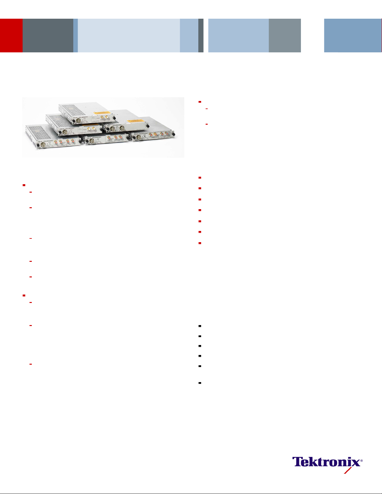
Optical Sampling Modules
80C07B • 80C08C • 80C10B • 80C11 • 80C12 • 80C25GBE Data Sheet
Tributary Telecom and Datacom
80C07B and 80C12 provide Excellent Optical Sensitivity and Broad
Wavelength Test Capability
2 Multirate Telecom Conformance Testing Solutions
1
Mb/s (OC-3/STM-4) through 11.317 Gb/s (10GFC w/
Features & Benefits
10 Gb/s Tel
100 Gb/s and 40 Gb/s Telecom and Datacom
ecom and Datacom
Highly Accurate ER Calibrated (Extinction Ratio) Measurement Option
for Increased Repeatability and Transferability of the Measurement
80C08C and 80C12 (w/ Option 10G) – Low-noise, High Optical
Sensitivity, and Broad Wavelength Conformance Testing for 10 GbE,
40 GbE (R4), 1 00 GbE (X10) LAN, WAN, FEC, 10G Fibre Channel,
and 10 Gb/s
80C11 30 GHz Optical Bandwidth Conformance Testing and
Characterization for 10 Gb/s Telecom and Datacom Standards and
FEC Rates
80C08C and 80C11 Integrated Clock Recovery supports All Current
10 Gb/s Standards or User-defined Rates from 9.8 to 12.6 Gb/s (CR4)
80C12 Clo
80A07 Clock Recovery Module (Sold Separately)
80C10B 80 GHz Optical Bandwidth and Lowest Noise Capability for
Performa
RZ, or Optical Duobinary Data Formats
New 80C10B Option F1 provides Optical Reference Receivers for
Conformance Testing of 25.781 Gb/s (100GBase-R4), 27.739 Gb/s
(100GBase-R4 w/ FEC), 39.813 Gb/s (OC-768/STM-256, VSR-2000),
41.25 Gb/s (40GBase-R1), 43.018 Gb/s (OTU3, VSR-2000 w/ FEC,
4x10G LA
New 80C25GBE module provides 65 GHz full bandwidth and
fully integrated selectable reference rece iver filtering, enabling
conformance testing at either 1310 nm or 1550 nm for 27.739G
(100GBase-LR4+FEC and 100GBase-ER4+FEC), and 25.781G
(100GBase-LR4 and 100GBase-ER4 )
Telecom Standards and FEC Rates
ck Recovery for 10 Gb/s Rate is supported by the 80A05 or
nce Testing and Signal Characterization of 40 Gb/s NRZ,
NPHYOTU3)inasinglemodule
80C07B, 80C1
from 125*
FEC) and Multirate Datacom Conformance Testing Solutions for Fibre
Channel, Gigabit Ethernet, and Infiniband Standards
Applications
High-speed Optical Communications Testing
Extinction Ratio and Q-factor Measurements
Eye-pattern and Pulse Shape Analysis
Relaxation Oscillation Testing
Optical Signal Analysis
Compliance Testing
NRZ, RZ, and Optical Duobinary Signal Characterization
DSA8200*2Series Sampling Oscilloscope
Optical Modules
The DSA8200 Series Sampling Oscilloscope, when configured with one or
more optic
Telecom (125 Mb/s to 44.50 Gb/s) or Datacom (Gigabit Ethernet, 10 GbE,
40 GbE, 100 GbE, Fibre Channel to 10 GFC, and InfiniBand) applications,
as well as general-purpose optical component testing.
Each optical module includes all the elements necessary for optical testing:
*1125 Mb/s is supported by selecting 155 Mb/s rate.
2
*
Also compatible with CSA/TDS8200, CSA/TDS8000B, and CSA/TDS8000 sampling oscilloscopes.
al sampling modules, provides complete optical test solutions for
Optical-to-Electrical Converter
Average Power Monitor
One or More Reference Receiver Filters
A Full Bandwidth Optical Path
Optional Integrated Clock Recovery (80C12 clock recovery is provided
using the 80A05 or 80A07 Clock Recovery Module – sold separately)
Universal Optical Input Connector

Data Sheet
New: ER Calibrated (Extinction Ratio)
To increase the level of transferability of the ER measurem ent, ER
calibration o f the module against a calibrated, known, high ER source. This
optional feature is available on most modules (see Ordering).
Calibrated reduces the uncertainty of ER results through Tektronix
Optical Sampl
Module Description
80C07B Multirate, Datacom and Telecom The 80C07B module is a broad wavelength (700 to 1650 nm) multirate optical sampling module optimized for testing
80C08C Mult
High Sensit
80C10B Multirate Datacom and Telecom 40 Gb/s
and 100 Gb/s
ultirate, 10 Gb/s Datacom and Telecom
80C11 M
80C12 Multirate Datacom and Telecom The 80C12 module is a broad wavelength (700 to 1650 nm) multirate optical sampling module providing 1G, 2G, 4G, 8G,
C25GBE Multirate Datacom 100 Gb/s
80
ing Modules
irate, Broad Wavelength,
ivity 10 Gb/s
datacom/telecom signals from 125 to 2500 Mb/s.
With its amplified O/E converter design, this module provides excellent signal-to-noise performance, allowing users to
examine low-power optical signals. The 80C07B can be optionally configured with clock recovery that supports 125, 155,
622, 1063, 1250, 2125, 2488, 2500, and 2666 Mb/s rates.
The 80C08C m
testing for
applicatio
10.709 Gb/s
With its am
sensitivi
recovery o
The 80C10B module provides integrated and selectable reference receiver filtering, enabling conformance testing at either
1310 nm or 1550 nm for 39.813 Gb/s (OC-768/STM-256), 41.25 Gb/s (40GBase-LR), and 43.018 Gb/s [OTU3, (4×10G LAN
PHY)] rates. In addition to the filter rates, the user may also choose selectable bandwidths of 30 GHz, 65 GHz, and 80 GHz
for 80C10B for optimal noise vs. bandwidth performance for accurate signal characterization. The 80C10B is optionally
available with Option F1 which extends filter selections to include 27.739 Gb/s (100GBase-LR4 + FEC and 100GBase-ER4
+ FEC), and 25.781 Gb/s (100GBase-LR4 and 100GBase-ER4 ). The 80C10B is also optionally available in a bundled
ordering configuration which includes a 70+ GHz electrical sampling channel.
The 80C
dataco
its hig
compon
defined rate in the continuous range from 9.8 to 12.6 Gb/s.
user-
and 10G telecom and datacom testing. This highly flexible module can be configured to support either lower data rate
applications (1 to 8.5 Gb/s) or a wide variety of 10 Gb/s applications. The low data rate applications include: 1, 2, 4, and
8G Fibre Channel, multilane standards such as 10GBase-X4 and 4-Lane 10 Gb/s Fibre Channel, and Infiniband SDR and
DDR rates. The supported 10 Gb/s application includes both datacom and telecom application. The supported 10 Gb/s
datacom applications include 10GbE, 40GbE-R4, 100GbE-SR10 applications at 9.953, 10.3125, 11.0957 Gb/s and 10G
Fibre Channel applications at 10.51875 Gb/s and 11.317 Gb/s. The 80C12 also provides telecom rate testing at 9.953,
10.664, and 10.709 Gb/s.
With its amplified O/E converter design, this module provides excellent signal-to-noise performance and high optical
sensitivity, allowing users to examine low power level optical signals. Clock recovery for the 80C12 is provided using the
80A05 or 80A07 (sold separately).
C25GBE module provides 65 GHz full bandwidth and integrated and selectable reference receiver filtering, enabling
80
nformance testing at either 1310 nm or 1550 nm for 27.739G (100GBase-LR4+FEC and 100GBase-ER4+FEC), and
co
.781G (100GBase-LR4 and 100GBase-ER4).
25
odule is a broad wavelength (700 to 1650 nm) multirate optical sampling module providing datacom rate
10GbE, 40GbE-R4, 100GbE-SR10 applications at 9.953, 10.3125, 11.0957 Gb/s and 10G Fibre Channel
ns at 10.51875 Gb/s and 11.317 Gb/s. The 80C08C also provides telecom rate testing at 9.953, 10.664, and
.
plified O/E converter design, this module provides excellent signal-to-noise performance and high optical
ty, allowing users to examine low power level optical signals. The 80C08C can be optionally configuredwithclock
ptions that can support any standard or user-defined rate in the continuous range from 9.8 to 12.6 Gb/s.
11 module is a long wavelength (1100 to 1650 nm) multirate optical sampling module optimized for testing 10 Gb/s
m and telecom standard rates at 9.953, 10.3125, 10.51875, 10.664, 10.709, 11.0957, 11.317, and 14.025 Gb/s. With
h optical bandwidth of up to 30 GHz (typical) it is well suited for general-purpose high-performance 10 Gb/s optical
ent testing. The 80C11 can be optionally configured with clock recovery options that can support any standard or
2 www.tektronix.com
Optical Sampling Modules — 80C07B • 80C08C • 80C10B • 80C11 • 80C12 • 80C25GBE
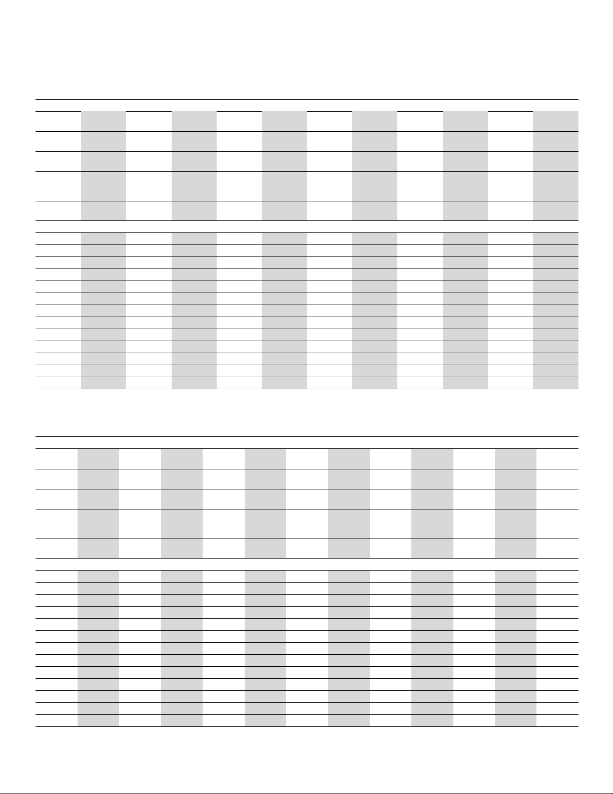
Optical Modules: 80C07B
Module
Opt.
Bandwidth
(GHz)
Wavelength
Range (nm)
Fibre Input
(μm)
Mask Test
Sensitivity
(dBm)
Number of
Channels
Rates Supported: ■=Filter, ♦=Optical Clock Recovery, ⊕=Electrical Clock Recovery
125 Mb/s*
155 Mb/s
622 Mb/s
1063 Mb/s
1250 Mb/s
2125 Mb/s
2488 Mb/s
2500 Mb/s
3.125 Gb/s
3.188 Gb/s
3.32 Gb/s
4.25 Gb/s
9.95 Gb/s
*1125 Mb/s is supported by selecting 155 Mb/s rate.
F1 F2 F3 F4 F5 F6 F7 F8 F9 F10
2.52.52.52.52.52.52.52.52.52.52.5
700-1650 700-1650 700-1650 700-1650 700-1650 700-1650 700-1650 700-1650 700-1650 700-1650 700-1650
9or50or
62.5
9or50or
62.5
9or50or
62.5
9or50or
62.5
9or50or
62.5
–22 –22 –22 –22 –22 –22 –22 –22 –22 –22 –22
11111111111
1
■■■■
■■■■
■ ■■■
■■■■
■ ■■■
■■■■
■■■■■■■■■■
■■■■■■■■■■
80C07B
9or50or
62.5
9or50or
62.5
9or50or
62.5
9or50or
62.5
9or50or
62.5
CR1
9or50or
62.5
♦
♦
♦
♦
♦
♦
♦
♦
Optical Modules: 80C08C, 80C10B, 80C11, and 80C25GBE
Module
Opt. CR1 CR2 CR4
Bandwidth
10 10 10 10 80 65 65 30 30 30 30 30
80C08C 80C10B 80C25GBE 80C11
(GHz)
elength
Wav
ge (nm)
Ran
Fibre Input
(μm)
Mask Test
-1650
700
9or50or
62.5
-1650
700
9or50or
62.5
-1650
700
9or50or
62.5
–15 –15 –15 –15
-1650
700
9or50or
62.5
0-1330
129
0-1620
152
99999999
–7
Sensitivity
(dBm)
Number of
111111111111
Channels
Rates Supported: ■=Filter, ♦=Optical Clock Recovery, ⊕=Electrical Clock Recovery
9.95 Gb/s
10.31 Gb/s
10.52 Gb/s
10.66 Gb/s
10.71 Gb/s
11.1 Gb/s
11.3 Gb/s
■
■
■
■
■
■
■
♦ ♦ ♦■♦♦♦♦
♦♦♦
♦♦
♦
♦
♦
♦
14.025 Gb/s
25.78 Gb/s
27.74 Gb/s
39.81 Gb/s
41.25 Gb/s
43.02 Gb/s
■■
■■
■■
129
152
F1
0-1330
0-1620
129
152
0-1330
0-1620
110
0-1650
CR1 CR2 CR3 CR4
110
0-1650
110
0-1650
110
0-1650
–8 –8 –9 –9 –9 –9 –9
■
■
■
■
♦♦
♦♦♦
■
■
■■■■■
■■■
■■
110
0-1650
♦
♦
♦
♦
www.tektronix.com 3
Data Sheet
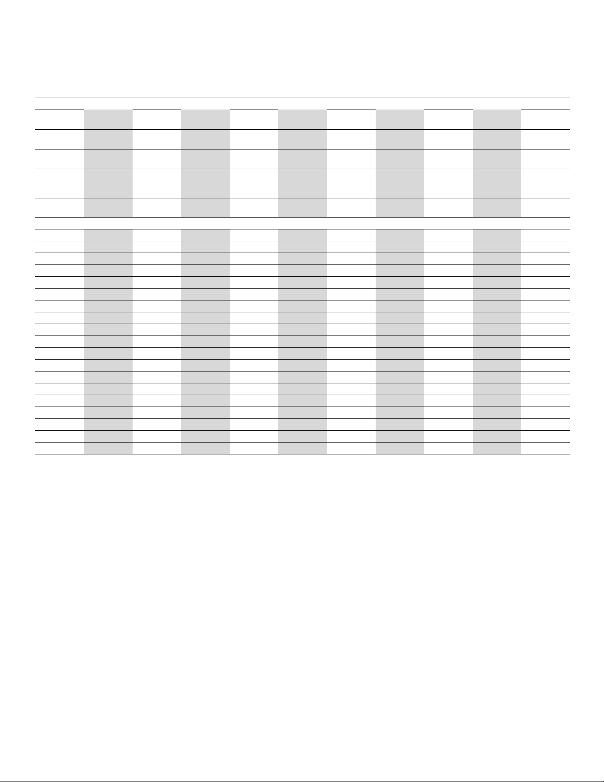
Optical Modules: 80C12
Module
Opt.
Bandwidth
F1 F2 F3 F4 F5 F6
4.25 9 9 4.25 9 9 9 10
(GHz)
Wavelength
700-1650 700-1650 700-1650 700-1650 700-1650 700-1650 700-1650 700-1650
Range (nm)
Fibre Input
9 or 50 or 62.5 9 or 50 or 62.5 9 or 50 or 62.5 9 or 50 or 62.5 9 or 50 or 62.5 9 or 50 or 62.5 9 or 50 or 62.5 9 or 50 or 62.5
(μm)
Mask Test
–19 –19 –19 –19 –19 –19 –19 –14
Sensitivity
(dBm)
Number of
11111111
Channels
Rates Supported: ■=Filter, ♦=Optical Clock Recovery, ⊕=Electrical Clock Recovery
155 Mb/s
622 Mb/s
1063 Mb/s
■■
1250 Mb/s
2125 Mb/s
■■■■ ■
2488 Mb/s
2500 Mb/s
3.125 Gb/s
3.188 Gb/s
■■■■
■■■■
3.32 Gb/s
4.25 Gb/s
8.5 Gb/s*
5
■■ ■■
■■ ■■■■
9.95 Gb/s
10.31 Gb/s*
5
10.52 Gb/s
10.66 Gb/s
10.71 Gb/s
11. 1 G b /s
11. 3 G b /s
*3With 80A05 or 80A07.
4
With 80A05 Option 10G or 80A07.
*
5
*
Draft version of the 8.5GFC fi lter. T11 committee redefined this filter at the April 2008 meeting. New 8.5GFC filter, as defined in ANSI FC-PI-4 (Rev 8),
Option 10G modules only; and is identified as 10GBase-R.
80C12
FC 10G CR*
3
CR*
♦♦
♦♦
♦♦
♦♦
♦♦
♦♦
♦♦
♦♦
♦♦
■
♦♦
♦♦
80A07
■
■
■
■
■
■
■
is identical to the 10GBase-R 10.313G filter and is available for 80C12
♦
♦
♦
♦
♦
♦
♦
4
4 www.tektronix.com

Optical Sampling Modules — 80C07B • 80C08C • 80C10B • 80C11 • 80C12 • 80C25GBE
Electrical Clock Recovery
Product Feature / Characteristic
80A05
Standard Option 10G
OC3/STM1 155.52 Mb/s
OC12/STM4 622.08 Mb/s
Fibre Channel 1.063 Gb/s
Gigabit Ethernet 1.25 Gb/s
SAS Gen I 1.50 Gb/s ♦*
2 GB Fibre Channel 2.125 Gb/s
OC48/STM16 2.488 Gb/s
2 GB Ethernet 2.50 Gb/s
PCI Express I 2.50 Gb/s ♦*
Infiniband®SDR 2.50 Gb/s
2.5G G.709 FEC 2.666 Gb/s
SAS Gen II 3.0 Gb/s ♦*
XAUI, 10GBase-X 3.125 Gb/s
10 GB Fibre Channel ×4 3.188 Gb/s
4 GB Fibre Channel 4.25 Gb/s
FB-DIMM1
3.2, 4.0, 4.8 Gb/s ♦*
PCIExpress/Infinband DDR 5.0 Gb/s ♦*3,*
FB-DIMM2
4.8, 6.4, 8.0, 9.6 Gb/s ♦*
OIF CEI 6+ Gb/s ♦*
2x XAUI
8 GB Fibre Channel*
5
6.25 Gb/s
8.50 Gb/s
OC192/STM64 9.953 Gb/s
XFP/XFI
9.95-11.2
10GBase-W 9.953 Gb/s
10GBase-R*
5
10.31 Gb/s
10 GB Fibre Channel 10.51 Gb/s
G.975 FEC 10.66 Gb/s
G.709 FEC 10.71 Gb/s
■■
■■■
■■■
■■■
4
4
♦*
■■■
■■■
■■■
4
4
♦*
■■
■■
4
4
♦*
■■
■■
■■■
3,*4
4
3,*4
3
■
■■
3
♦*
■
■■
■
■
■
OIF CEI 11+ Gb/s
10 GbE w/ FEC 11.10, 11.3 Gb/s
Super FEC 12.50 Gb/s
■
■
User User selectable Partial Full
*3With 80A05 or 80A07.
4
With 80A05 Option 10G or 80A07.
*
5
ft version of the 8.5GFC fi lter. T11 committee redefined this filter at the April 2008 meeting. New 8.5GFC filter, as defined in ANSI FC-PI-4 (Rev 8), is identical to the 10GBase-R 10.313G filter and is available for 80C12
*
Dra
n 10G modules only; and is identified as 10GBase-R.
Optio
80A07
♦*
■
■
♦*
♦*
■
♦*
♦*
■
■
■
■
♦*
■
■
♦*
♦*
♦*
■
♦*
♦*
3
3
3
3
3
3
3
3
3
3
3
www.tektronix.com 5

Data Sheet
Characteristics
Optical Sampl
Module App licat ion Type
80C07B Tributary Datacom/Telecom Standard Included: OC-48/STM-16 (2.488 Gb/s),
ing Module Characteristics
Standards and Supported Filtering Rates*
Infiniband SDR, 2 GbE (2.500 Gb/s);
Optional (choose any two): OC-3/STM-1
6
Number of Input
Channels
Effective
Wavelength
Range
Calibrated
Wavelengths
1 700 nm to 1650 nm 780 nm, 850 nm,
1310 nm, and 1550 nm
(±20 nm)
(155 Mb/s), OC-12/STM-4 (622 Mb/s),
Fibre Channel (1.063 Gb/s), GbE (1.250 Gb/s),
2G Fibre Channel (2.125 Gb/s)
80C08C 10 Gb/s Datacom/Telecom OC-192/STM-64 (9.953 Gb/s), 10GBase-W
(9.953 Gb/s), 10GBase-R, 40GBase-R4,
100GBase-SR10 (10.31 Gb/s), 10G Fibre
1 700 nm to 16
50 nm
780 nm, 850
1310 nm, an
(±20 nm)
d1550nm
Channel (10.52 Gb/s), ITU-T G.975 FEC
(10.664 Gb/s), ITU-T G.709 (10.709 Gb/s),
10 GbE FEC (11.1 Gb/s), 10 GFC FEC
(11.3 Gb/s), 10GBase-LRM, 40GBase-SR4,
100GBase-SR10, 40GBase-LR4
80C10B 100 Gb/s and 40 Gb/s
Telecom and Datacom
OC-768/STM-256 (39.813 Gb/s), OTU3, VSR-2000
FEC (43.018 Gb/s), OTU3 (44.5 Gb/s), 40GBase-LR
1 1310 nm and
1550 nm
1310 nm and 1550 nm
(±20 nm)
(41.25 Gb/s), 100GBase-R4 (25.781 Gb/s),
100GBase-R4 FEC (27.739 Gb/s)
80C11 10 Gb/s Datacom/Telecom OC-192/STM-64 (9.953 Gb/s), 10GBase-W
(9.953 Gb/s), 10GBase-R, 40GBase-LR4
1 1100 nm to 1650 nm 1310 nm and 1550 nm
(±20 nm)
(10.31 Gb/s), 10G Fibre Channel (10.52 Gb/s),
ITU-T G.975 FEC (10.664 Gb/s), ITU-T G.709
(10.709 Gb/s), 10 GbE FEC (11.1 Gb/s),
10 GFC FEC (11.3 Gb/s), 40GBase-LR4,
16GFC (14.025 Gb/s)
80C12
1to8.5Gb/s
Datacom/Telecom
Fibre Channel (1.063 Gb/s), 2G Fibre Channel
(2.125 Gb/s), 4G Fibre Channel (4.250 Gb/s),
10GBase-X4 (3.125 Gb/s), 8G Fibre Channel
(8.50 Gb/s)*
5
, 10GFC-X4 (3.1875 Gb/s),
1 700 nm to 1650 nm 850 nm, 1310 nm, and
1550 nm (±20 nm)
VSR5-3318 (3.318 Gb/s), 1x Infiniband SDR
(2.5 Gb/s), 10GBase-LRM, 40GBase-SR4,
100GBase-SR10, 40GBase-LR4
10 Gb/s Datacom/Telecom OC-192/STM-64 (9.953 Gb/s), 10GBase-W
(9.953 Gb/s), 10GBase-R*
5
, 40GBase-R4,
100GBase-SR10 (10.31 Gb/s), 10G Fibre Channel
(10.52 Gb/s), ITU-T G.975 FEC (10.664 Gb/s),
ITU-T G.709 (10.709 Gb/s), 10 GbE FEC
(11.1 Gb/s), 10 GFC FEC (11.3 Gb/s)
80C25GBE 100 Gb/s Datacom 100GBase-LR4 (25.781, FEC 27.739),
11
100GBase-ER4 (25.781, FEC 27.739)
*5Draft version of the 8.5GFC fi lter. T11 committee redefined this filter at the April 2008 meeting. New 8.5GFC filter, as defined in ANSI FC-PI-4 (Rev 8), is identical to the 10GBase-R 10.313G filter and is available for 80C12
Option 10G modules only; and is identified as 10GBase-R.
6
Bandwidths shown are warranted unless printed in an italic typeface which represents a typical value. 80C08C, 80C12: Bandwidths and optical filters valid for OMA ≤500 uW (1550/1310 nm), OMA ≤860 uW (850 nm), OMA
*
≤1020 uW (780 nm).
Note: Refer to Optical Sampling Modules User Manual for more detailed information.
310 nm and
550 nm
1
310 nm and 1550 nm
1
±20 nm)
(
nm,
6 www.tektronix.com

Optical Sampling Modules — 80C07B • 80C08C • 80C10B • 80C11 • 80C12 • 80C25GBE
Optical Sampling Module Characteristics (Cont.)
Module
80C07B Option CR1: 155 Mb/s, 622 Mb/s,
Clock Recovery (Optional) Clock Recovery Outputs Unfiltered Optical
Bandwidth*
±Clock, ±Data 2.5 GHz
1.063 Gb/s, 1.250 Gb/s,
2.125 Gb/s, 2.488 Gb/s,
2.500 Gb/s, 2.666 Gb/s
80C08C Option CR1: 9.953 Gb/s,
Clock, Clock/16 10 GHz
10.31 Gb/s;
Option CR2: 10.31 Gb/s,
10.52 Gb/s;
Option CR4: Continuous from
9.8Gb/sto12.6Gb/s
6
80C10B*
80C11 Option CR1: 9.953 Gb/s;
Option CR2: 9.953 Gb/s,
10.664 Gb/s;
CR1: Clock, Clock/16, Data;
CR2, CR3, CR4: Clock,
Clock/16
80 GHz
30 GHz
Option CR3: 9.953 Gb/s,
10.709 Gb/s;
Option CR4: Continuous between
9.8Gb/sto12.6Gb/s
80C12
Provided by 80A05 or 80A07
(sold separately)
ELECTRICAL SI GNAL OUT 9GHz(for all options
except 10G)
10 GHz (Option 10G)
*6Bandwidths shown are warranted unless printed in an italic typeface which represents a typical value. 80C08C, 80C12: Bandwidths and optical filters valid for OMA ≤500 uW (1550/1310 nm), OMA ≤860 uW (850 nm), OMA
≤1020 uW (780 nm).
Absolute Maximum
6
Nondestructive
Optical Input
5 mW average; 10 mW
peak power at wavelength
of highest responsivity
1 mW average; 10 mW
peak power at wavelength
of highest responsivity
20 mW average; 60 mW
peak power at wavelength
of highest relative
5 mW average; 10 mW
peak power at wavelength
of highest responsivity
1 mW average; 10 mW
peak power at wavelength
of highest responsivity
Internal Fibre
Diameter
62.5 μm/125 μm
Multi Mode
62.5 μm/125 μm
Multi Mode
9 μm/125 μm
Single Mode
responsivity
9 μm/125 μm
Single Mode
62.5 μm/125 μm
Multi Mode
Optical Sampling Module Characteristics (Cont.)
Module
cal Return
Opti
Loss
80C07B >14 dB (Multi Mode)
Fibre Input
Accepted
Single or Multi Mode 0.50 μW at 155 Mb/s, 622 Mb/s,
>24 dB (Single
Mode)
80C08C >14 dB (Multi Mode)
Single or Multi Mode 1.7 μWatallfilter rates (1550/1310 nm,
>24 dB (Single
Mode)
80C10B
80C11
80C12 >14 dB (Multi Mode)
>30 dB
>30 dB
Single Mode
Single Mode 5.5 μWatallfilter rates;
Single or Multi Mode 1.3 μW(allfilters except Option 10G)
>24 dB (Single
Mode)
80C25GBE
>30 dB
Single Mode
ptical Noise (Typical)
RMS O
ptical Noise (Maximum)
RMS O
1.0 μW at 155 Mb/s, 622 Mb/s,
1063 Mb/s, 1250 Mb/s;
0.70 μW at 2.488/2.500 Gb/s
1063 Mb/s, 1250 Mb/s;
1.5 μW at 2.488/2.500 Gb/s
3.0 μWatallfilter rates (1550/1310 nm) Standard
no CR)
1310 nm 1550 nm 1310 nm 1550 nm
21 uW (25.8,
27.7 Gb/s)
26 uW (30 GHz)
28 uW (39.8 Gb/s
-43.0Gb/s)
44 uW (65 GHz)
72 uW (80 GHz)
15 uW (25.8,
27.7 Gb/s)
19 uW (30 GHz)
20 uW (39.8 Gb/s
-43.0Gb/s)
33 uW (65 GHz)
55 uW (80 GHz)
38 uW (25.8,
27.7 Gb/s)
45 uW (30 GHz)
50 uW (39.8 Gb/s
-43.0Gb/s)
75 uW (65 GHz)
130 uW (80 GHz)
35 uW (30 GHz)
38 uW (39.8 Gb/s
60 uW (65 GHz)
105 uW (80 GHz)
8.0 μWatallfilter rates;
7.0 μW at 14.025 GHz
10.0 μWat20GHz
20.0 μWat30GHz
10.0 μW at 14.025 GHz
14.0 μWat20GHz
30.0 μWat30GHz
2.5 μW(allfilters except Option 10G)
2.4 μW (’Full BW’ and Option 10G filters)
5.0 μW (’Full BW’ and Option 10G filters)
1310 nm 1550 nm 1310 nm 1550 nm
21 uW (25.8,
27.7 Gb/s)
44 uW (65 GHz)
15 uW (25.8,
27.7 Gb/s)
33 uW (65 GHz)
38 uW (25.8,
27.7 Gb/s)
75 uW (65 GHz)
60 uW (65 GHz)
Independent
Channel Deskew
Standard
Standard
28 uW (25.8,
27.7 Gb/s)
- 43.0 Gb/s)
Standard
Standard
Standard
28 uW (25.8,
27.7 Gb/s)
www.tektronix.com 7

Data Sheet
Optical Sampling Module Characteristics (Cont.)
Module
Offset Capability
80C07B Standard Standard
80C08C Standard Standard
80C10B, 80C
25GBE
Standard Standard
80C11 Standard Standard
80C12 Standard Standard
*7Smallest power level for mask test. Values represent theoretical typical sensitivity of NRZ eyes for comparison purposes. Assumes instrument peak- peak noise consumes most of the mask margin.
Power Meter Power Meter Range Power Meter Accuracy
+4 dBm to –30 dBm
0dBmto–30dBm
+13 d Bm to –21 dBm
+4 dBm to –30 dBm
0dBmto–30dBm
5% of reading –22 dBm at 155 Mb/s,
5% of readin
5% of readin
g
g
5% of reading –12 dBm at all filter rates;
5% of reading –19 dBm (for all options
–14 dBm (for Option 10G)
Mask Test Optical
Sensitivity*
622 Mb/s;
–20 dBm at
2488/2500 Mb/s
–16 dBm at al
25.8 and 27.
–8 dBm (1550
–7 dBm (1310
39.813 to 43
–7 dBm (155
–6 dBm (131
l filter rates
7Gb/s:
nm) and
nm);
.018 Gb/s:
0nm)and
0nm)
–5 dBm at 20 GHz;
–6 dBm at 30 GHz
except Option 10G)
7
Optical Sampling Module Characteristics (Cont.)
Module
80C07B
80C08C
80C10B
80C11
*8Low ER signals (ER ≤ 6 dB): signal passes 802.3ae-like mask (scaled horizontally for bit rate); 105samples
in mask. High ER signals (ER > 6 dB): signal passes OC-192-like mask (scaled horizontally for bit rate);
5
10
samples in mask.
Extinction Ratio Calibrated Accuracy (Opt.
ence Filter
Refer
ge (Gb/s)
in Ran
—
…11.3
9.9
01 ER Calibrated)*
Repeatability
(Typical)
(to itself
and to other
80Cxx-Opt. 01)
Option not available
±0.6% (–0.39 dB /
+0.42dBat12dB)
—
9.9…11.3
±0.6% (–0.39 dB /
Option not available
+0.42dBat12dB)
8
±1.2% (–0.76 dB /
+0.92dBat12dB)
±1.2% (–0.76 dB /
+0.92dBat12dB)
Accuracy
Physical Characteristics
Module
Dimensions (mm/in.)
Width Height Depth Net
Weight
(kg/lb.)
80C07B 165/6.5 25/1.0 305/12.0 <1.36/<3.0
80C08C 165/6.5 25/1.0 305/12.0 <1.22/<2.7
80C10B 165/6.5 25/1.0 305/12.0 <2.61/<5.75
80C11 165/6.5 25/1.0 305/12.0 <1.22/<2.7
80C12 165/6.5 25/1.0 305/12.0 <2.61/<5.75
80C25GBE 165/6.5 25/1.0 305/12.0 <2.61/<5.75
Ordering Information
80C07B
Multirate Datacom and Telecom Optical Sampling Module.
Includes: User Manual, FC/PC Optical Connector.
80C08C
Multirate Datacom and Telecom Optical Sampling Module.
Includes: User Manual, FC/PC optical connector.
80C10B*
Multirate Optical Sampling Module – 80 GHz.
Includes: User manual, FC/PC optical connector.
80C11
Multirate Datacom and Telecom Optical Sampling Module.
Includes: User Manual, FC/PC optical connector.
80C12
Multirate Datacom and Telecom Optical Sampling Module.
Includes: User Manual, FC/PC optical connector. Clock recovery is available using
the 80A05 or 80A07. The 80C12 Multirate Telecom and Datacom Optical Sampling
Module is available with a wide variety of factory-configured signal conditioning
options. These options provide a variety of reference receiver filtering and unfiltered
signal acquisition bandwidths. The user must specify one of the following options
when ordering this module.
80C25GBE
Multirate Optical Sampling Module – 65 GHz.
Includes: User manual, FC/PC optical connector.
7
8 www.tektronix.com

Optical Sampling Modules — 80C07B • 80C08C • 80C10B • 80C11 • 80C12 • 80C25GBE
Options
Option
80C07B
Description
Opt. CR1 155/622/1063/1250/2125/2488/2500/2666 Mb/s clock/data
recovery.
User must select any one (1) of the following filter options:
Opt. F1 155, 622 Mb/s
Opt. F2 155, 1063 Mb/s
Opt. F3 155, 1250 Mb/s
Opt. F4 155, 2125 Mb/s
Opt. F5 622, 1063 Mb/s
Opt. F6 622, 1250 Mb/s
Opt. F7 622, 2125 Mb/s
Opt. F8 1063, 1250 Mb/s
Opt. F9 1063, 2125 Mb/s
Opt. F10 1250, 2125 Mb/s
80C08C
Opt. CR1 9.953, 10.31 Gb/s clock recovery
Opt. CR2 10.31, 10.52 Gb/s clock recovery
Opt. CR4 Continuous rate clock recovery supporting any standard or
user-definablerateintherangefrom9.8to12.6Gb/s
Opt. 01 ER Calibrated (when ordered with new module); module will
only work on mainframe with Windows XP and oscilloscope
FW V 5.0 and higher.
ER Calibrated can be ordered as an upgrade to an existing
module; order Opt. 01 + Opt. IFC (factory installation); factory
installation is required; module will only work on mainframe
with Windows XP and oscilloscope FW V 5.0 and higher.
80C10B*
7
80C10BE1 Bundled ordering configuration includes 80C10B plus one
80E06 single-channel 70+ GHz electrical module
Opt. F1 43.018, 39.813, 41.25, 27.739, 25.781 filters, 65 GHz full
bandwidth
80C11
Opt. CR1 9.953 Gb/s clock recovery
Opt. CR2 9.953, 10.66 Gb/s clock recovery
Opt. CR3 9.953, 10.71 Gb/s clock recovery
Opt. CR4 Continuous rate clock recovery supporting any standard or
user-definablerateintherangefrom9.8to12.6Gb/s
Opt. 01 ER Calibrated (when ordered with new module); module will
only work on mainframe with Windows XP and oscilloscope
FW V 5.0 and up.
ER Calibrated can be ordered as an upgrade to an existing
module; order Opt. 01 + Opt. IFC (factory installation); factory
installation is required; module will only work on mainframe
with Windows XP and oscilloscope FW V 5.0 and higher.
80C12
The user must specify one of the following options when ordering this module:
Opt. F1 1063, 2125, 4250 Mb/s filters, 4.25 GHz full bandwidth
Opt. F2 2125, 4250, 8500 Mb/s filters, 9 GHz full bandwidth
Opt. F3 1063, 2125, 8500 Mb/s filters, 9 GHz full bandwidth
Opt. F4 2125, 3125, 3187.5, 4250 Mb/s filters, 4.25 GHz full bandwidth
Opt. F5 3125, 3187.5, 4250, 8500 Mb/s filters, 9 GHz full bandwidth
Opt. F6 2125, 3125, 3187.5, 8500 Mb/s filters, 9 GHz full bandwidth
Opt. FC 3125, 3187.5, 3318, 8500 Mb/s filters, 9 GHz full bandwidth
Opt. 10G 8.5, 9.95, 10.31, 10.52, 10.66, 10.71, 11.1, 11.3 Gb/s filters,
10 GHz full bandwidth
*7Smallest power level for mask test. Values represent theoretical typical sensitivity of NRZ eyes for
comparison purposes. Assumes instrument peak-peak noise consumes most of the mask margin.
Service
Option
Description
Opt. C3 Calibration Service 3 Years
Opt. C5 Calibration Service 5 Years
Opt. D1 Calibration Data Report (includes frequency response curves
for all included reference receiver filters)
Opt. D3 Calibration Data Report 3 Years (with Opt. C3)
Opt. D5 Calibration Data Report 5 Years (with Opt. C5)
Opt. R3 Repair Service 3 Years
Opt. R5 Repair Service 5 Years
Optical Connector Accessories
While the FC/PC connector is standard with the 8000 Series optical sampling
modules, the input connector type can be interchanged with any of the following
standard adapters:
Adapters
Adapter
ST/PC
D4/PC
Biconic 119-4515-xx
FC/PC
SMA 2.5
SC/PC
DIN/PC 47256
HP/PC
SMA
DIAMOND 3.5
Note: For LC connector please use LC to FC/PC patch cable and connect to the default FC/PC.
Order
119-4513-xx
119-4514-xx
119-5115-xx
119-4517-xx
119-5116-xx
119-4546-xx
119-4556-xx
119-4557-xx
119-4558-xx
Product(s) are manufactured in ISO registered facilities.
www.tektronix.com 9

Data Sheet
10 www.tektronix.com

Optical Sampling Modules — 80C07B • 80C08C • 80C10B • 80C11 • 80C12 • 80C25GBE
www.tektronix.com 11

Data Sheet
Contact Tektronix:
ASEAN / Australa
Balkans, Israel, South Africa and other ISE Countries +41 52 675 3777
Central East Eu
Mexico, Central/South America & Caribbean 52 (55) 54247900
rope, Ukraine, and the Baltics +41 52 675 3777
Central Europe & Greece +41 52 675 3777
Luxembourg +44 (0) 1344 392400
Asia, and North Africa +41 52 675 3777
Middle East,
The N etherlands 090 02 021797
People’s Rep
United Kingdom & Ireland +44 (0) 1344 392400
For other areas contact Tektronix, Inc at: 1 (503) 627-7111
ublic of China 86 (10) 6235 1230
Republic of
sia (65) 6356 3900
Austria +41 52 675 3777
Belgium 07 81 601
Brazil +55 (11) 3759-7627
Canada 1 (800) 661-5625
Denmark +4580881401
Finland +41526
France +33(0)169868181
Germany + 49 (221) 94 77 400
Hong Kong (852
India (91) 80-42922600
Italy +39 (02) 25086 1
Japan 81 (3) 67
Poland +41 52 675 3777
Portugal 80 08 12370
Korea 82 (2) 6917-5000
Russia & CIS +7 (495) 7484900
South Africa +27 11 206 8360
Spain (+34)
Sweden 020 08 80371
Switzerland +41 52 675 3777
Tai wa n 886 (
USA 1 (800) 426-2200
75 3777
) 2585-6688
14-3010
Norway 800 16098
901 988 054
2) 2722-9622
Updated 5 August 2009
66
www.tektronix.com
For Further Information. Tektronix maintains a comprehensive, constantly expanding
collection of application notes, technical briefs and other resources to help engineers working
on the cutting edge of technology. Please visit www.tektronix.com
t © Tektronix, Inc. All rights reserved. Tektronix products are covered by U.S. and foreign patents,
Copyrigh
d pending. Information in this publication supersedes that in all previously published material.
issued an
tion and price change privileges reserved. TEKTRONIX and TEK are registered trademarks of
Specifica
x, Inc. All other trade names referenced are the service marks, trademarks, or registered trademarks
Tek t ro n i
espective companies.
of their r
30 Nov 2009 85W-15964-16
 Loading...