

Page 1

80A06 PatternSync
Trigger Module
Instructions
www.tektronix.com
*P071174401*
071-1744-01
Safety Summary
To avoid potential hazards, use this product only
as specified.
While using this product, you may need to access
other parts of the system. Read the General
Safety Summary in other system manuals for
warnings and cautions related to operating the
system.
To avoid fire or personal injury
Ground the product. This product is indirectly
grounded through the grounding conductor of
the mainframe power cord. To avoid electric
shock, the grounding conductor must be connected to earth ground. Before making connections to the input or output terminals of the
product, ensure that the product is properly
grounded.
Observe all terminal ratings. To avoid fire or shock
hazard, observe all ratings and markings on the
product. Consult the host instrument documentation for further ratings information before making connections to the host instrument.
Do not apply a potential to any terminal,
including the common terminal, that exceeds the
maximum rating of that terminal.
Do not operate with suspected f ailures. If you
suspect there is damage to this product, have it
inspected by qualified service personnel.
Do not operate in wet/damp conditions.
Do not operate in an explosive atmosphere.
Keep product surfaces clean and dry.
Safety Terms In This Manual
CAUTION. Caution statements identify
conditions or practices that could result in
damage to the equipment or other property.
Safety symbols on the
product
CAUTION
Refer to Product Manual
Environmental Considerations
Product End-of-Life Handling
Observe the following guidelines when
recycling an instrument or component:
Equipment Recycling. This product complies
with the European Union’s requirements according to Directive 2002/96/EC on waste electrical
and electronic equipment (WEEE). For information about recycling options, check the Support/
Service section of the Tektronix Web site
(www.tektronix.com).
Restriction of Hazardous Substances
This product has been classified as Monitoring and Control equipment, and is outside the
scope of the 2002/95/EC RoHS Directive.
This product is known to contain lead and
hexavalent chromium.
Product Description
The 80A06 PatternSync Trigger module requires
the 8000 series product software version 2.4 or
later. This module extends the triggering
capabilities of the mainframes listed in the
Specifications table in this document by
providing a frame synchronous (pattern) trigger.
The pattern trigger can be created from any
data-related clock, such as a recovered clock
signal, a user-supplied clock, a sub-clock, or
super-clock. This module can also be used with
the 82A04 Phase Reference Module to provide
down to 200 fs
The 80A06 module supports the use of the
80SJNB Advanced Jitter, Noise and BER
Analysis Software. Standard acquisition and
Framescan are also supported.
The 80A06 module is programmable from the
mainframe user interface or the GPIB interface.
Figure 1: 80A06 PatternSync module
Installing and Removing the Module
This module installs directly into any small
module slot in the listed mainframes. See the
mainframe documentation for proper installation
and removal of modules.
CAUTION. Instrument modules are extremely
static sensitive. Always ground yourself
when handling modules.
timebase jitter.
rms
Connector Care
Use extra care when attaching or removing SMA
connectors. Turn only the nut, not the cable.
Align the connectors carefully before turning the
nut. Use light finger pressure to make the initial
connection. Then tighten the nut lightly with a
wrench. Ideally, the SMA connectors should be
tightened to 56 N-cm (5 in-lb) with a torque
wrench.
Operation
When using this module with 80SJNB Advanced
Jitter, Noise and BER Analysis Software, use a
Phase Reference module installed in your
mainframe to ensure the most accurate
measurements.
The 80A06 accepts a user-supplied clock signal
and divides it by a programmed amount to
generate a frame trigger at the 80A06 TRIGGER
OUT connector. The trigger signal is not routed
internally and should be routed to the TRIGGER
DIRECT INPUT connector of the mainframe.
The trigger user interface of the mainframe
allows you to program the module to divide the
input clock signal by an integral multiple of the
length of the repetitive frame being applied to the
device under test (DUT), generating a
frame-synchronous trigger output.
The 80A06 module also provides a buffered
copy of the input clock at the CLOCK OUT
connector. This signal can be used for clocking
other equipment or as the phase reference clock
input for the 82A04 Phase Reference Module.
Specifications
Electrical
Characteristic
Mainframe interface Tekprobe®-Sampling,
Applicable mainframes DSA8200, TDS8000,
Number of channels One
Input and output connectors SMA female
Input/output impedance 50 Ω
Maximum non-destruct range 2.5 V
Maximum operating range 2.0 V
Maximum DC offset ± 5.0 VDC
Input electrical return loss
>15 dB 150 MHz to 10 GHz
>10 dB 10GHzto20GHz
Input/output coupling
CLOCK IN AC
CLOCK OUT AC
TRIGGER OUT DC, ground referenced
Supported clock rates
Minimum 150 MHz
Maximum 12.5 GHz
Input clock prescaler ratios
>150 MHz to ≤3.5 GHz
>3.5 GHz to ≤7GHz
>7 GHz to ≤12.75 GHz
Specification
Level 3.
Hot switching is
permitted.
CSA8000, TDS8000B,
CSA8000B, TDS8200,
CSA8200
pk-pk
pk-pk
12.75 GHz (typical)
1
4
8
16
Copyright E Tektronix. All rights reserved.
Page 2
Electrical (continued)
Characteristic Specification
Programmable pattern
1,2
length
Minimum 2
Maximum 223(8,388,608)
Front panel output amplitudes
CLOCK OUT (50 Ω,AC
coupled)
150 MHz to 8.0 GHz 500 mV
8.0 GHz to 12.75 GHz 250 mV
TRIGGER OUT (50 Ω,DC
coupled, ground referenced)
Output high level 0 V
Output low level -- 550 mV (typical)
Front panel output rise and fall
times
CLOCK OUT <60 ps (typical)
TRIGGER OUT <60 ps (typical)
System trigger jitter generation
DSA8200, CSA/TDS8000B,
CSA/TDS8200
Input clock >1.2 GHz <1.3 ps
Input clock ≤1.2 GHz
DSA8200 & CSA/TDS8000
Input clock >1.2 GHz <1.6 ps
Input clock ≤1.2 GHz
DSA8200 & CSA/TDS8200
with 80A06 and 82A04
modules
Minimum input sensitivity
150 MHz to 8.0 GHz 100 mV
8.0 GHz to 12.75 GHz 200 mV
1
DSA8200, CSA/TDS8000, CSA/TDS8000B, and
CSA/TDS8200 mainframe user interface or GPIB
configuration.
2
The 80A06 is programmed to within the hardware range of
the module (a pre-scaler followed by a counter with a
minimum count of 30) for the least-common-multiple count.
Environmental and Mechanical
Characteristic
Weight 0.4 kg (0.6 lbs)
Dimensions
Height 25 mm (1.0 in)
Width 79 mm (3.1 in)
Depth 135 mm (5.3 in)
Environmental conditions Refer to the host instrument
Electromagnetic
compatibility
850 fs
<3 mUI
1.5 mUI
1.0 ps
<3 mUI
1.5 mUI
<200 fs
50 mV
50 mV
Specification
specifications
Refer to the host instrument
specifications
pk-pk
pk-pk
rms
rms
rms
pk-pk
pk-pk
pk-pk
pk-pk
rms
(typical)
rms
rms
rms
(typical)
rms
rms
(typical)
(typical)
(typical)
(typical)
(typical)
(typical)
(typical)
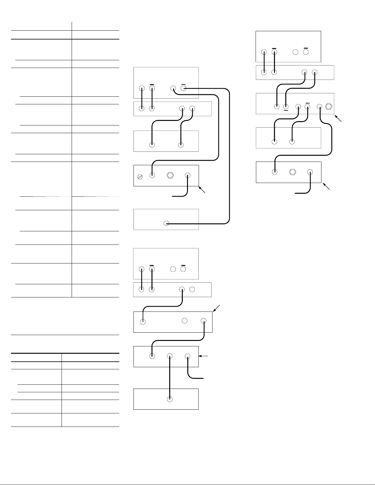
Setup Diagrams
The following illustrations show typical setup
configurations that use the 80A06 PatternSync
Module with other module types installed in a
mainframe.
Differential data setup
Pattern Generator
Data Clock
DUT
80E04
module
Trig Out
Clock In
To mainframe
Trigger Direct Input
82A04 Phase Ref module
Optical data setup
Pattern Generator
Data Clock
DUT
Optical cable
Optical In
Clock Out
Clock In
82A04 Phase Ref module
Trig Out
80A06
PatternSync
module
80C08C
optical
module
Clock1/16 Clock
80A06
PatternSync
module
To mainframe
Trigger Direct Input
Clock recovery setup
Pattern Generator
Data Clock
DUT
Clock Out
OutIn
80A05
80E04
module
Trig Out
Clock In
To mainframe
Trigger Direct Input
clock recovery
module
80A06
PatternSync
module
Accessories
The following accessories are shipped with the
80A06 PatternSync Trigger module:
S 80A06 Instructions 071-1744-xx
S 8000 Series Product 020-2543-xx
Documentation CD-- ROM
S (2) 12 inch SMA cables 174-1364-xx
Functional Check
Use the following procedure to verify that the
80A06 PatternSync module is recognized by the
host mainframe.
1. After installing the module, power on the
mainframe and wait for the scope application
to fully boot.
2. Select the Utilities menu and then select
System Properties.
3. Click the Modules tab.
4. Click the + next to the channel number
where the 80A06 module is installed.
5. Verify that the module nomenclature and
serial number are listed.
Warranty Information
For warranty information, go to
www.tektronix.com, click Support, and then
select Look Up Tektronix Warranty.
 Loading...