

Page 1

User Manual
80A05
Electrical Clock Recovery Module
071-1467-01
This document applies to firmware version 2.0.0
and above.
www.tektronix.com
Page 2

Copyright © Tektronix. All rights reserved. Licensed software products are owned by Tektronix or its subsidiaries or
suppliers, and are protected by national copyright laws and international t reaty provisions.
Tektronix products are covered by U.S. and foreign patents, issued and pending. Information in this publication supercedes
that in all previously published material . Specifications and price change privileges reserved.
TEKTRONIX and TEK are registered trademarks of Tektronix, Inc.
Contacting Tektronix
Tektronix, Inc.
14200 SW Karl Braun Drive
P.O. Box 500
Beaverton, OR 97077
USA
For product information, sales, service , and technical support:
H In North America, call 1-800-833-9200.
H Worldwide, visit www.tektronix.com to find contacts in your area.
Page 3

Warranty 2
Tektronix warrants that this product will be free from defects in mat erials and workmanship for a period of one (1) year
from the date of shipment. If any such product proves defective during this warranty period, Tektronix, at its option, either
will repair the defective product without charge for parts and labor, or will provide a replacement in exchange for the
defective product. Parts, modules and replacement products used by Tektronix for warrant y work may be new or
reconditioned to like new performance. All replaced parts, modules and products become the property o f Tektronix.
In order to obtain service under this warranty, Customer must notify Tektronix of the defect before the expiration of the
warranty period and make suitable arrangements for the performance of service. Customer shall be responsible for
packaging and shipping the defective product to the service center designated by Tektronix, with shipping charges prepaid.
Tektronix shall pay for the return of the product to Customer if the shipment is to a location within the country in which the
Tektronix service center is l ocated. Customer shall be responsible for paying all shipping charges, duties, taxes, and any
other charges for products returned to any other locations.
This warranty shall not apply to any defect, failure or damage caused by improper use or improper or inadequate
maintenance and care. Tektronix shall not be obligated to furnish service under this warranty a) to repair damage resulting
from attempts by personnel other than Tektronix representatives to install, repair or service the product; b) to repair
damage resulting from improper use or connec tion to incompatible equipment; c) to repair any damage or malfunc tion
caused by the use of non-Tektronix supplies; or d) to service a product that has been modified or integrated with other
products when the effect of such modification or integration increases the time or difficulty of servicing the product.
THIS WARRANTY IS GIVEN BY TEKTRONIX WITH RESPECT TO THE PRODUCT IN LIEU OF ANY OTHER
WARRANTIES, EXPRESS OR IMPLIED. TEKTRONIX AND ITS VENDORS DISCLAIM ANY IMPLIED
WARRANTIES OF MERCHANTABILITY OR FITNESS FOR A PARTICULAR PURPOSE. TEKTRONIX’
RESPONSIBILITY TO REP AIR OR REPLACE DEFECTIVE PRODUCTS IS THE SOLE AND EXCLUSIVE REMEDY
PROVIDED TO THE CUSTOMER FOR BREACH OF THIS WARRANTY. TEKTRONIX AND ITS VENDORS WILL
NOT BE LIABLE FOR ANY INDIRECT, SPECIAL, INCIDENTAL, OR CONSEQUENTIAL DAMAGES
IRRESPECTIVE OF WHETHER TEKTRONIX OR THE VENDOR HAS ADVANCE NOTICE OF THE POSSIBILITY
OF SUCH DAMAGES.
Page 4

Page 5

Table of Contents
General Safety Summary iii.......................................
Environmental Considerations v...................................
Preface vii...................................................
Manual Structure vii................................................
Related Documentation vii...........................................
Getting Started 1............................................
Product Description 1..............................................
Options and Accessories 3...........................................
Installation 4.....................................................
Electrostatic Discharge 5............................................
Static Controlled Workstation 5......................................
Operating Basics 7..........................................
Usage 7.........................................................
Front Panel 7.....................................................
LED 7...........................................................
Input and Output Connectors 8.......................................
System Interaction 8...............................................
Programmer Interface Commands 9...................................
User Adjustments 9................................................
Specifications 11.............................................
80A05 Electrical Clock Recovery Module User Manual
i
Page 6

Table of Contents
ii
80A05 Electrical Clock Recovery Module User Manual
Page 7

General Safety Summary
Review the following safety precautions to avoid injury and prevent damage to
this product or any products connected to it.
To avoid potential hazards, use this product only as specified.
Only qualified personnel should perform service procedures.
While using this product, you may need to access other parts of the system. Read
the General Safety Summary in other system manuals for warnings and cautions
related to operating the system.
ToAvoidFireor
Personal Injury
Ground the Product. This product is indirectly grounded through the grounding
conductor of the mainframe power cord. To avoid electric shock, the grounding
conductor must be connected to earth ground. Before making connections to the
input or output terminals of the product, ensure that the product is properly
grounded.
Observe All Terminal Ratings. To avoid fire or shock hazard, observe all ratings
and markings on the product. Consult the product manual for further ratings
information before making connections to the product.
Do Not Operate Without Covers. Do not operate this product with covers or panels
removed.
Avoid Exposed Circuitry. Do not touch exposed connections and components
when power is present.
Do Not Operate With Suspected Failures. If you suspect there is damage to this
product, have it inspected by qualified service personnel.
Do Not Operate in Wet/Damp Conditions.
Do Not Operate in an Explosive Atmosphere.
Keep Product Surfaces Clean and Dry.
Symbols and Terms
80A05 Electrical Clock Recovery Module User Manual
Terms in this Manual. These terms may appear in this manual:
WARNING. Warning statements identify conditions or practices that could result
in injury or loss of life.
CAUTION. Caution statements identify conditions or practices that could result in
damage to this product or other property.
iii
Page 8

General Safety Summary
Terms on the Product. These terms may appear on the product:
DANGER indicates an injury hazard immediately accessible as you read the
marking.
WARNING indicates an injury hazard not immediately accessible as you read the
marking.
CAUTION indicates a hazard to property including the product.
Symbols on the Product. The following symbols may appear on the product:
CAUTION
Refer to Manual
WARNING
High Voltage
Protective Ground
(Earth) Terminal
iv
80A05 Electrical Clock Recovery Module User Manual
Page 9

Environmental Considerations
This section provides information about the environmental impact of the
product.
Product End-of-Life
Handling
Observe the following guidelines when recycling an instrument or component:
Equipment Recycling. Production of this equipment required the extraction and
use of natural resources. The equipment may contain substances that could be
harmful to the environment or human health if improperly handled at the
product’s end of life. In order to avoid release of such substances into the
environment and to reduce the use of natural resources, we encourage you to
recycle this product in an appropriate system that will ensure that most of the
materials are reused or recycled appropriately.
The symbol shown to the
left indicates that this
product complies with the
European Union’s requirements according to Directive 2002/96/EC on waste
electrical and electronic
equipment (WEEE). For
information about recycling options, check the
Support/Service section of
the Tektronix Web site
(www.tektronix.com).
Restriction of Hazardous
Substances
80A05 Electrical Clock Recovery Module User Manual
This product has been classified as Monitoring and Control equipment, and is
outside the scope of the 2002/95/EC RoHS Directive. This product is known to
contain lead, cadmium, and hexavalent chromium.
v
Page 10

Environmental Considerations
vi
80A05 Electrical Clock Recovery Module User Manual
Page 11

Preface
Manual Structure
Related Documentation
This is the user manual for the 80A05 Electrical Clock Recovery module. The
manual covers capabilities, installation, operation, and specifications of the
module.
This manual is composed of the following chapters:
H Getting Started shows you how to configure and install your module and
lists standard and optional accessories.
H Operating Basics describes controlling the module using the front panel and
the instrument user interface, system interaction, the programmer interface,
and user adjustments.
H Specifications lists all typical and guaranteed specifications for this product.
See the following list for your main instrument operation and service documents.
These documents are available on the product documentation CD--ROM (with
the exception of Online Help).
Manual name Description
Online Help An online help system, integrated with the User Interface application that ships with the
main instrument.
Programmer Online Guide An alphabetical listing of the programming commands and other information related to
controlling the instrument over the GPIB.
Service Manual Describes how to service the instrument to the module level. This optional manual must
be ordered separately.
Specifications and Performance Verification
Manual
Provides a list of all specifications and performance verification procedures for the main
instrument and modules.
80A05 Electrical Clock Recovery Module User Manual
vii
Page 12

Preface
viii
80A05 Electrical Clock Recovery Module User Manual
Page 13
Getting Started
The Tektronix 80A05 Electrical Clock Recovery Module will recover the clock
from electrical data for all Tektronix electrical modules. The 80A05 Electrical
Clock Recovery Module provides a solution for triggering the main instrument
from single-ended or differential electrical signals. The 80A05 can also be used
as a general purpose clock recovery solution.
This module can be used in the following mainframes:
H DSA8200 Digital Serial Analyzer
H CSA8000, CSA8000B, and CSA8200 Communications Signal Analyzer
H TDS8000, TDS8000B, and TDS8200 Digital Sampling Oscilloscope
NOTE. Proper operation of the 80A05 module requires that the operating system
software installed on the main instrument is version 2.0 or greater. To display
the version installed, select About from the Help menu in the main instrument
user interface.
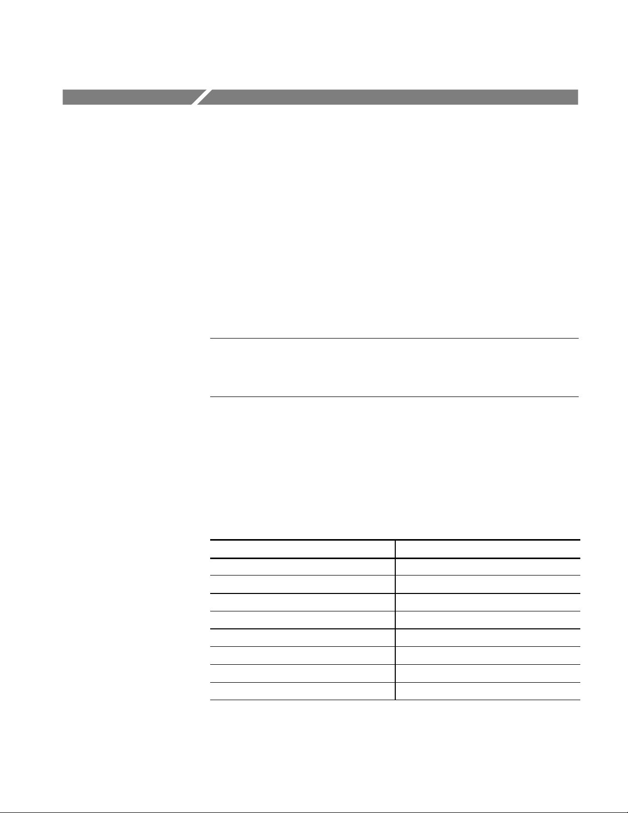
Product Description
The module provides the characteristics shown in Table 1. See Specifications for
a full list of product specifications.
Table 1: 80A05 module characteristics
Characteristic Value or description
Number of inputs 2
Input/output impedance 50 Ω
Input/output connectors SMA
Input/output coupling DC
Recovered clock timing jitter 50 Mb/s to 2.7 Gb/s: 0.5% of unit interval
Maximum input voltage 2.0 V
Analog bandwidth 3dB to 20 GHz
Minimum clock recovery sensitivity 8mV
p-p
p-p
80A05 Electrical Clock Recovery Module User Manual
1
Page 14

Getting Started
CAUTION. To prevent electrostatic damage to the main instrument and modules,
follow the precautions described in this manual and the documentation
accompanying your instrument.
(See Electrostatic Discharge starting on page 5.)
There are five (six, Option 10G) identical SMA female connectors on the front
panel: two data inputs, two data outputs, one TRIGGER CLOCK output, and
one 10G CLK output (Option 10G). Refer to Figures 2 and 3 on page 8.
The module receives power through the Tekprobe--Sampling interface. The
Power LED indicates the clock recovery circuitry is on and programmed to the
requested bit rate.
CAUTION. To prevent electrostatic damage to the main instrument and module,
follow the precautions described in this manual and the documentation
accompanying your instrument. (See Electrostatic Discharge starting on
page 5.)
2
80A05 Electrical Clock Recovery Module User Manual
Page 15
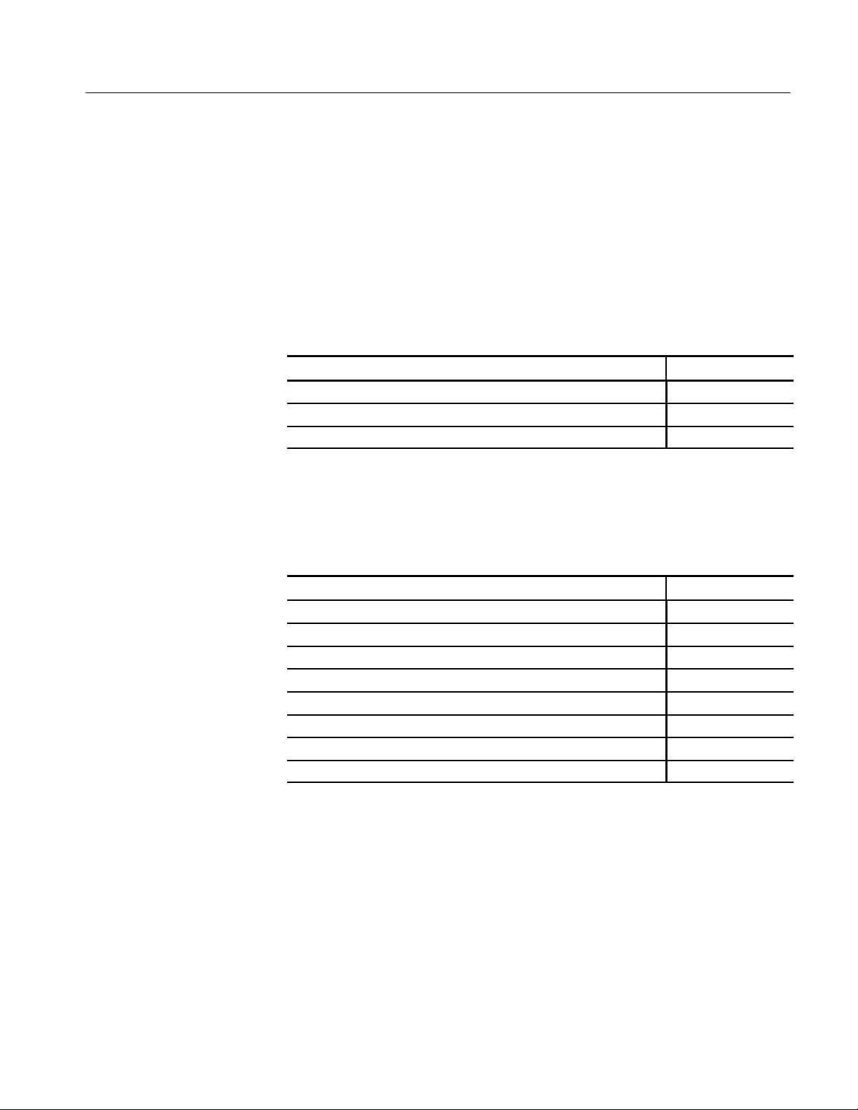
Options and Accessories
This section lists the standard and optional accessories available for the module.
Getting Started
Options
Standard Accessories
Optional Accessories
Option 10G adds >4.25 Gb/s Clock recovery.
The following accessories are shipped with the module:
Table 2: Standard accessories
Item Part number
80A05 Electrical Clock Recovery Module User Manual 071-1467-xx
(5) SMA, male, 50 Ω termination caps. Option 10G (6) 011-0182-xx
Transit case, ESD protective 004-5091-xx
You can order the following accessories for use with the module. Consult a
current Tektronix catalog for additions, changes, and details:
Table 3: Optional accessories
Item Part number
2X attenuator (SMA male-to-female) 015-1001-xx
5X attenuator (male-to-female) 015-1002-xx
Coaxial cable 015-0560-xx
Power divider 015-0565-xx
Asymmetrical power divider 015-0683-xx
SMA accessory kit 020-1693-xx
CSA8000 & TDS8000 Service Manual 071-0438-xx
DSA8200 Service Manual 071-2047-xx
80A05 Electrical Clock Recovery Module User Manual
3
Page 16

Getting Started
Installation
The 80A05 module fits into one of the large module compartments on the front
panel of an 8000 series instrument. See Figure 1.
To install a module, first power off the instrument using the front-panel
On/Standby switch. Then place the module in a compartment, and slowly push it
in with firm pressure. Once the module is seated, turn the hold-down screws on
the module to tighten the module into place. See Figure 1. When an 80A05
module is installed into one of the large slots, one of the smaller slots will be
disabled. Refer to the instrument’s online help to identify the disabled slot.
CAUTION. To prevent damage to the module or instrument, never install or
remove a module when the instrument is powered on or when either input
connector is unprotected.
Module compartment
ejectors
Loosen
80A05 module
Loosen
Figure 1: Installing a module
NOTE. When removing your module, first loosen the hold-down screws, and then
use the module ejector on the main instrument to eject the module.
4
80A05 Electrical Clock Recovery Module User Manual
Page 17

Getting Started
Electrostatic Discharge
To prevent electrostatic damage to the main instrument and modules, follow the
precautions described in this manual and the manuals that come with your
instrument.
Circuitry in the module is very susceptible to damage from electrostatic
discharge or from overdrive signals. Be sure to only operate the module in a
static-controlled environment. Be sure to discharge to ground any electrostatic
charge that may be present on the center and outer connectors of cables before
attaching the cable to the module.
Know your signal source. If it is capable of delivering overvoltages, it is safer to
not depend on the signal source settings for protection, but instead use an
external attenuator that protects the input from the worst-case conditions. For
example, for a 10 V maximum source connected to a 1 V maximum module, use
a 10X attenuator. Where possible, connect your cables to the signal source first,
and to the module second.
CAUTION. To prevent damage from electrostatic discharge, install the attached
50 Ω terminations on the I/O connectors before removing the module from an
instrument, storing, or when not in use. Store the module in a static-free
container, such as the shipping container. Whenever you move the module from
one instrument to another, use a static-free container to transport the module.
Static Controlled
Workstation
T o prevent damage to the module, discharge to ground any electrostatic charge
that may be present on the center and outer conductors of cables before
attaching the cables to the module.
T o prevent damage to the module, do not create an ESD antenna by leaving
cables dangling off the module input with the other end open.
T o prevent damage to the module or instrument, never install or remove a
module when the instrument is powered on.
Always use a wrist strap (provided with your instrument) when handling
modules or making signal connections. Wear antistatic clothing and work in a
static-free workstation when using modules.
T o prevent damage to the module or instrument, do not apply a signal outside
the Maximum Input Voltage Swing for your module.
For information on creating a static-controlled workstation, consult the Electronic Industries Association document, EIA-625; Requirements for Handling
Electrostatic-Discharge-Sensitive (ESDS) Devices.
80A05 Electrical Clock Recovery Module User Manual
5
Page 18

Getting Started
6
80A05 Electrical Clock Recovery Module User Manual
Page 19

Operating Basics
Usage
This chapter familiarizes you with the operation of your module. This chapter
describes the front-panel controls and connectors, interaction of the module with
your main instrument, user adjustments, and the programmer interface.
Figures 2 and 3 on page 8, show the front panel of the module and identify the
connectors and indicators.
CAUTION. To prevent damage to your module or instrument, do not apply a
signal outside the Maximum Input Voltage Swing for your module.
T o prevent electrostatic damage to the instrument and modules, follow the
precautions described in this manual and the documentation accompanying your
instrument. (See Electrostatic Discharge starting on page 5.)
Always use a wrist strap (provided with your instrument) when handling
modules or making signal connections.
Front Panel
Hold-down screws
LED
The input circuitry in your module is very susceptible to damage from overdrive
signals and electrostatic discharge. Never apply a DC or peak voltage greater
than the Maximum Operating Range (see Table 4 on page 11) of your module.
Only operate the instrument and module in a static-controlled environment.
The 80A05 module contains three primary features:
Use these to secure the module in the instrument module compartment once
connected. Turn clockwise to secure and counterclockwise to release. To prevent
damage to the module, use the compartment ejectors to remove the module from
the compartment (see Figure 1 on page 4 for the location of the ejectors).
The 80A05 module has one LED on its front panel. When on, it indicates the
module’s clock recovery output has been selected as the trigger source. The LED
is off when the module is not selected as the trigger source.
80A05 Electrical Clock Recovery Module User Manual
7
Page 20

Operating Basics
Figure 2: 80A05 module front panel
Figure 3: 80A05- 10G module front panel
Input and Output
Connectors
System Interaction
The connectors on the front panel of the 80A05 module provide connections for
the input and output signals. All connectors are SMA female connectors.
Connector Care. Never attach a cable to a sampling-module connector if the cable
has a worn or damaged connector because you may damage the sampling-module connector. Use extra care when attaching or removing a cable from the
connectors. Turn only the nut, not the cable. When attaching a cable to a
sampling-module connector, align the connectors carefully before turning the
nut. Use light finger pressure to make this initial connection. Then tighten the
nut lightly with a wrench.
NOTE. For best repeatability and to prolong connector life, use a torque wrench,
and tighten the connection to the range of 79-112 N⋅cm (7-10 in lb).
If the module connectors will receive heavy use, such as in a production
environment, you should install adapters (such as a Tektronix part number
015-0549-xx for 3.5 mm connectors) on the module to make connections to the
device under test.
The mainframe acts as the host via the large module receptacles for this module.
The remainder of the system interaction for this module is contained in the
documentation set included with your main instrument.
8
80A05 Electrical Clock Recovery Module User Manual
Page 21

Programmer Interface Commands
The remote-programming commands for all modules are documented in the
Programmer Online Guide for your main instrument.
User Adjustments
All module setups, parameters, and adjustments are controlled by the instrument.
To save, recall, or change any module settings, use the instrument menus or
front-panel controls or consult the Online Help and other documentation that
accompanied your main instrument.
Operating Basics
80A05 Electrical Clock Recovery Module User Manual
9
Page 22

Operating Basics
10
80A05 Electrical Clock Recovery Module User Manual
Page 23

Specifications
This section contains specifications for the 80A05 Electrical Clock Recovery
Module. All specifications are guaranteed unless noted as “typical.” Typical
specifications are provided for your convenience but are not guaranteed.
All specifications apply to all models of module unless noted otherwise. To meet
specifications, three conditions must first be met:
H The instrument must have been calibrated/adjusted at an ambient tempera-
ture between +20 _C and +30 _C.
H The oscilloscope must have been operating continuously for 20 minutes
within the operating temperature range specified.
H The instrument must be in an environment with temperature, altitude, and
humidity, within the operating limits described in these specifications
Table 4: Module characteristics
Specifications Characteristics
Mainframe interface Tekprobe®-Sampling, Level 3. Hot switching is not permitted.
Number of inputs 2
Input and output
connectors
Data input/output
coupling
Maximum
non-destruct range
Maximum operating
range
Maximum operating
range
Maximum DC offset ±2.0 VDC
Electrical Return Loss Data in+, data in--,data out+, data out--:
Electrical data attenuation
Propagation delay Either inputs:
Propagation Delay
mismatch
SMA
DC
Either inputs: 2.5 V
Single-ended operation:
Either input: 2.0 V
Complementary operation:
Each input: 1 V
15dB or better DC to 10GHz
Data in+, data in--,data out+, data out--:
10dB or better 10GHz to 20GHz
DC to 12.5 GHz: 6.6 dB ±0.6 dB
875 ps
Either inputs:
<15 ps
pk-pk
pk-pk
pk-pk
80A05 Electrical Clock Recovery Module User Manual
11
Page 24

Specifications
v
a
Recoveredclocktim
-
50M/bsto2.7G/bs:<
1.0%ofunitinterva
l
ingjitter2.7G/bsto6.375G/bs:<2.5psRMS
Table 4: Module characteristics (Cont.)
Specifications Characteristics
Input/output
impedance
Step response aberrations
Analog bandwidth ±3 dB, DC to 20 GHz
Front panel output
amplitudes
Front panel rise and
fall times
50 Ω
±2% or less over zone 10 ns to 20 ps before step transition
±10% or less for the first 300 ps following step transition
+1% --5% or less over zone 300 ps to 3 ns following step transition
+1% --3% or less over zone 3 ns to 100 ns following step transition
±0.5% after 100 ns following step transition
Trigger clock output: 400 mV
10G clock output: 500 mV
Trigger clock output: 300 ps
10G clock output: 30 ps
pk-pk
pk-pk
Recoveredclock tim- 50 M/bs to 2.7 G/bs: < 1.0% ofunit inter
ing jitter
2.7 G/bs to 6.375 G/bs: < 2.5 ps RMS
9.8 G/bs to 12.6 G/bs: < 2.0 ps RMS
Minimum clock recovery sensitivity
Single-ended operation:
150Mb/s to 2.7 G/bs: 10 mV
2.7 G/bs to 11.19 G/bs: 15 mV
11.19G/bsto12.5G/bs 20mV
pk-pk
pk-pk
pk-pk
Complementary operation:
Supported data rates
and formats
(without Option 10G)
150Mb/s to 2.7 G/bs: 8 mV
2.7 G/bs to 11.19 G/bs: 12 mV
11.19G/bsto12.5G/bs 15mV
OC3/SMT1 155.52 Mb/s
OC12/STM4 622.08 Mb/s
FibreChannel 1.063 Gb/s
pk-pk
pk-pk
pk-pk
Gigabit Ethernet 1.250 Gb/s
2 Gigabit FibreCHannel 2.125 Gb/s
OC48/STM16 2.488 Gb/s
2 Gigabit Ethernet 2.500 Gb/s
InfiniBand 2.500 Gb/s
2.5G G.709 FEC 2.666 Gb/s
4 Gigabit FibreChannel 4.250 Gb/s
Supported user selected clock recovery
50 Mb/s to 2.7 Gb/s
3.000 Gb/s to 3.188 Gb/s
(without Option 10G)
l
Supported data rates
and formats added
with Option 10G
OC192/STM64 9.953 Gb/s
10GBase-W 9.953 Gb/s
10GBase-R 10.31 Gb/s
10G FibreChannel 10.51 Gb/s
G.975 FEC 10.66 Gb/s
G.709 FEC 10.71 Gb/s
10GbE w/FEC 11.10 Gb/s
12
80A05 Electrical Clock Recovery Module User Manual
Page 25

Table 4: Module characteristics (Cont.)
Specifications Characteristics
Supported user selected clock recovery
with Option 10G
50 Mb/s to 3.188 Mb/s
3.267 Gb/s to 4.250 Gb/s
4.900 Gb/s to 6.375 Gb/s
9.800 Gb/s to 12.60 Gb/s
Table 5: Environmental specifications
Specification Characteristics
Temperature Operating: +10 °Cto+40°C
Humidity Non-operating: 5% to 90% relative humidity
Operating: 20% to 80% relative humidity
Specifications
Table 6: Mechanical specifications
Specifications Characteristics
Weight 1.22 kg (2.70 lbs.)
Overall dimensions Height: 2.5 cm (1.0 in)
Width: 16.5 cm (6.5 in)
Depth: 30 cm (12 in)
Does not include connectors, connector savers, connector covers, push
buttons, or lock-down hardware protruding from the front or rear panels.
Construction material Chassis aluminum alloy;
Front panel plastic laminate;
Circuit boards glass-laminate;
Cabinet sleeve aluminum
Cabinet end covers aluminum
80A05 Electrical Clock Recovery Module User Manual
13
Page 26

Specifications
Table 7: Electromagnetic specifications
Specification Characteristic
Emissions The instrument meets or exceeds t he EMC requirements of the
following standards: Emissions European Community Requirements
(including EN 61326)
EN55011 Class A Radiated Emissions
EN55011 Class A Conducted Emissions
IEC 1000--3--2 Power Harmonic Current Emissions
Susceptibility The instrument meets or exceeds the EMC requirements of the
following standards:
EN61326--1 European Community Requirements
IEC 1000--4--2 Electrostatic Discharge Immunity
4 kV contact discharge
8 kV air discharge
Performance criteria B
14
80A05 Electrical Clock Recovery Module User Manual
 Loading...