

Page 1

Model 8007
Semiconductor Test Fixture
Instruction Manual
Contains Operating and Servicing Information
Page 2

WARRANTY
Keithley Instruments, Inc. warrants this product to be free from defects in material and workmanship for a period of I year
from date of shipment.
Keithley Instruments, Inc. warrants the following items for 90 days from the date of shipment: probes, cables, rechargeable
batteries, diskettes, and documentation.
During the warranty period, we will, at our’option, either repair or replace any product that proves to be defective,
To exercise this warranty, write or call your local Keithley representative, or contact Keithley headquarters in Cleveland, Ohio.
You will he given prompt assistance and return instructions. Send the product, transportation prepaid, to the indicated service
facility. Repairs will be made and the product returned, transportation prepaid. Repaired or replaced products are warranted for
the balance of the original warranty period, or at least 90 days.
LIMITATION OF WARRANTY
This warranty does not apply to defects resulting from product modification without Keithley’s express written consent, or
misuse of any product or part. This warranty also does not apply to fuses, software, non-rechargeable batteries, damage from
battery leakage, or problems arising from normal wear or failure to follow instructions.
THIS WARRANTY IS IN LIEU OF ALL OTHER WARRANTIES, EXPRESSED OR IMPLIED, INCLUDING ANY
IMPLIED WARRANTY OF MERCHANTABILITY OR FITNESS FOR A PARTICULAR USE. THE REMEDIES PROVIDED HEREIN ARE BUYER’S SOLE AND EXCLUSIVE REMEDIES.
NEITHER KEITHLEY INSTRUMENTS, INC. NOR ANY OF ITS EMPLOYEES SHALL BE LIABLE FOR ANY DIRECT,
INDIRECT, SPECIAL, INCIDENTAL OR CONSEQUENTIAL DAMAGES ARISING OUT OF THE USE OF ITS
INSTRUMENTS AND SOFTWARE EVEN IF KEITHLEY INSTRUMENTS, INC., HAS BEEN ADVISED IN ADVANCE
OFTHE POSSIBILITY OF SUCH DAMAGES. SUCH EXCLUDED DAMAGES SHALL INCLUDE, BUT ARE NOT LIMITED TO: COSTS OF REMOVAL AND INSTALLATION, LOSSES SUSTAINED AS THE RESULT OF INJURY TO ANY
PERSON, OR DAMAGE TO PROPERTY.
Page 3

Model 8007
Semiconductor Test Fixture
Instruction Manual
01989, Keith@ Instruments, Inc.
All rights reserved.
Cleveland, Ohio, U.S.A.
Second Printing, October 2000
Document Number: 8007-901-01 Rev. B
Page 4

Manual Print History
The print history shown hclow lists the printing dates of all Revisions and Addenda created for this manual. The
Revision Level letter increases alphabetically as the manual undergoes subsequent updates. Addenda, which are
released between Revisions, contain important change information that the user should incorporate immediately
into the manual. Addenda are numbered sequentially. When a new Revision is crcatcd, all Addenda associated
with the previous Revision of the manual arc incorporated into the new Revision of the manual. Each new Revision includes a revised copy of this print history page.
Revision A (Document Number 8007-901-01) . Janunry 1989
Addendum A (Document Number 8007-901-02) .._....,,,,,,,,,,,,,,,,,,,,,,,,,.,,,,,....,. Mnrch 1989
Revision B (Document Number X007-901-01) October2000
Page 5

SAFETY PRECAUTIONS
The following safety precautions should be observed before using the Model 8007 and the associated instruments.
This test fixture is intended for use by qualified personnel who recognize shock hazards and are familiar with the safety
precautions required to avoid possible injury. Read over this manual carefully before using the test fixture.
Exercise extreme caution when a shock hazard is present at the test fixture. User-supplied lethal voltages may be present
on the fixture or the connector jacks. The American National Standards Institute (ANSI) states that R shock hazard exists
when voltage levels greater than 30V RMS or 42.4V peak are present. A good safety practice is to expect that hazardous
voltage is present in any unknown circuit before measuring.
Inspect the connecting cables and test leads for possible wear, cracks, or breaks before each use
For maximum safety, do not touch the test fixture, test cables or any instruments while power is applied to the circuit
under test. Turn off the power and discharge any capacitors before connecting or disconnecting cables from the test fix-
ture. Also, keep the test fixture lid closed while power is applied to the device under test. Safe operation requires the use
of the lid interlock (see paragraph 22.1).
Do not touch any object which could provide a current path to the common side of the circuit under test or power line
(earth) ground. Always make measurements with dry hands while standing on a dry, insulated surface capable of withstanding the voltage being measured.
Do not exceed the maximum signal levels of the test fixture, as defined in the specifications and operation section of this
manual.
Connect the fixture
Instrumentation and accessories should not be connected to humans.
0 = screw terminal to safety earth ground using #18 AWG or larger wire (supplied accessory).
Page 6

Page 7

Safety Precautions
The following safety precautions should be observed before using
this product and any associated instrumentation. Although some
instruments and accessories would normally be used with nonhazardous voltages, there are situations where hazardous conditions
may be present.
This product is intended for use by qualified personnel who recognize shock hazards and are familiar with the safety precautions re-
quired to avoid possible injury. Read the operating infomntion
carefully before using the product.
The types of product users are:
Responsible body is the individual or group responsible for the use
and maintenance of equipment, for ensuring that the equipment is
operated within its specifications and operating limits, and for en-
suring that operators are adequately trained.
Operators use the product for its intended function. They must be
trained in electrical safety procedures and proper use of the instru-
ment. They must be protected from electric shock and contact with
hazardous live circuits.
Maintenance personnel perform routine procedures on the product
to keep it operating, for example, setting the line voltage or replac-
ing consumable materials. Maintenance procedures are described in
the manual. Tbe procedures explicitly state if the operator may perform them. Otherwise, they should be performed only by service
pW3tlllti
Service personnel arc trained to work on live circuits, and
safe installations and repairs of products. Only properly trained ser-
vice personnel may perfoorm installation and service procedures.
perform
Users of this product must be protected from electric shock at all
times. The responsible body must enwre that users are prevented
access and/or insulated from every connection point. In home cases,
connections must be exposed to potential human contact. Product
users in these circumstances most be trained to protect themselves
from the risk ofelectric shock. If the circuit is capable of operating
at or above IO00 volts, no conductive part of the circuit may be
CQXXXi.
As described in the International Electrotechnical Commission
(IEC) Standard IEC 664, digital multimeter measuring circuits
(e.g.. Keithley Models 175A, 199,2000,2001,2002, and 2010) are
Installation Category Il. All other instruments’ signal temtinals are
Installation Category I and must not be connected to mains.
Do not connect switchingcards directly tounlimited power circuits.
They are intended to be used with impedance limited sources.
NEVER connect switching cards directly to AC mains. When coonetting sources to switching cards, install protective devices to limit fault current and voltage to the card.
Before operating an instrument. make sore the line cord is connected to a properly grounded power receptacle. Inspect the connecting
cables, test leads, and jumpers for possible wear, cracks, or breaks
before each use.
For maximum safety, do not touch the product, test cables, or any
other instruments while power is applied to the circuit under test.
ALWAYS remove power from the entire test system and discharge
any capacitors before: connecting or disconnecting cables or jumpers, installing or removing switching cards, or making internal
changes, such as installing or removing jumpers.
Exercise extreme caution when a shock hazard is present. Lethal
voltage may be present on cable connector jacks or test fixtures. The
American National Standards btstitute (ANSI) states that a shock
hazard exists when voltage levels greater than 30V RMS, 42.4V
peak, or 60VDC are present. A good safety practice is to expect
that hazardous voltage is present
in
any
unknown
circuit
before
measuring.
Do not touch any object that could provide a current path to the
common side of the circuit under test or power line (earth) ground.
Always make measttrement8 with dry hands while standing on a
dry, insulated surface
measured.
capable
of withstanding the voltage being
Page 8
The instrument and accessories must be used in accordance with its
specifications and operating instructions or the safety of the equip
ment may be impaired.
The WARNING heading in a manual explains dangers that might
result in personal injury or death. Always read the associated information very carefully before performing the indicated procedure.
Do not exceed the maximum signal levels of the instruments and accessories. as defined in the specifications and operating informa-
tion, and as shown on the instrument or test fixture panels, or
switching card.
When fuses are used in a product, replace with same type and rating
for continued protection against fire hazard.
Chassis connections must only be used as shield connections for
measuring circuits, NOT as safety earth ground connections.
If you are using a test fixture, keep the lid closed while power is ap-
plied to the device under test. Safe operation requires the use of a
lid interlock.
,fa@
wire recommended in the user documentation.
Then
fer to the operating instructions located in the manual.
Then
sore 1000 volts or more, including the combined effect of normal
and common mode voltages. Use standard safety precautions to
avoid personal contact with these voltages.
screw is present. connect it to safety earth ground using the
symbol on an instrument indicates that the user should re-
symbol on an instrument shows that it can source or mea-
The CAUTION heading in a manual explains hazards that could
damage the instrument. Such damage may invalidate the warranty.
instrumentation and accessories shall not be connected to humans.
Before performing any maintenance, disconnect the line cord and
all test cables.
To maintain protection from electric shock and iirc, replacement
components in mains circuits, including the power transformer, test
leads, and input jacks, must be purchased from Keithley Instmmerits. Standard fuses, with applicable national safety approvals,
may be used if the rating and type are the same. Other components
that are not safety related may be purchased from other suppliers as
loog as they are equivalent to the original component. (Note that selected parts should be purchased only through Keithley Instruments
to maintain accuracy and functionality of the product.) If you are
tmsore about the applicability of a replacement component, call a
Keithley Instruments oflice for information.
To clean an instrument. use a damp cloth or mild, water based
cleaner. Clean the cxterior of the instrument only. Do not apply
cleaner directly to the instrument or allow liquids to enter or spill
on the instrument. Products that consist of a circuit board with no
case or chassis (e.g., data acquisition board for installation into a
computer) should never require cleaning if handled according to instructions. If the board becomes contaminated and operation is affected, the board should be returned to the factory for proper
cleaning/servicing.
Rev. 10199
Page 9

Specifications
DEVICE SOCKET CONFIGURATION: 1 each, 24- and 48-pin gold contact DIP
sockets (0.100 in. pin spacing, 0.300 to 0.600 in. wide, zero insertion force, replaceable).
CONNECTOR ,TYPE: 6 mass termination connectors (12 coaxial connections each, 72
total measurement pathways).
MAXIMUM SIGNAL VOLTAGE: ZOOV peak, signal or guard to any signal, guard, sub-
chassis, or chassis.
MAXIMUM SIGNAL CURRENT: 1A peak.
OFFSET CURRENT (18’C-ZS’C, ~60% R.H.): <1 pA (0.1 pA typical @ ~40% R.H.).
PATH ISOLATION (ltl’=C -28’C, < 60% R.H.):
Resistance: >lTQ (1OTQ typical @I <40% R.H.).
Capacitance (nominal): 2pF.
CROSSTALK @ 1MHz (typical): -6OdB (5Oa scurce and measure).
3 dB BANDWIDTH (typical): 4MH.z (5On source and measure).
INSERTION LOSS @ 1MHz (typical): O.ldB (50.Q source and 1 MQ measure).
PATH RESISTANCE: <la.
ENVIRONMENT:
Operating: 0°C to 5O”C, <SO% non-condensing R.H. up to 35’C.
Storage: -25°C to t7O”C.
GENERAL:
Socket Operating Life: >25,000 open-close cycles.
Lid Interlock Switching: <28VDC, 50mA.
Dimensions, Weight: 140mm high x 305mm wide x 292mm deep (5.5 in. x 12 in. x
11.5 in.). Net weight 3.5kg (7 Ibs., 12 oz.).
ACCESSORIES SUPPLIED:
Instruction manual
Model 8007-MTC-3:
Model 8007-PTB:
Model 8007-GND-3:
Model 236~ILC-3:
ACCESSORIES AVAILABLE:
Model 8007-MTC-3:
Model 8007~PTB: Prototyping PC board
Model 236-ILC-3: Interlock cable, 3m (loft.1
3-lug triax to mass termination connector cable assembly,
3m (IO ft.), two supplied
Prototyping PC board
Safety grounding cable
Interlock cable, 3m (10 ft.)
3-1~s hiax to mass termination connector cable assemblv,
3m rloft.)
Specifications are for guarded measurement configuration, including external cables.
Prices and specifications subject to change without notice.
Page 10
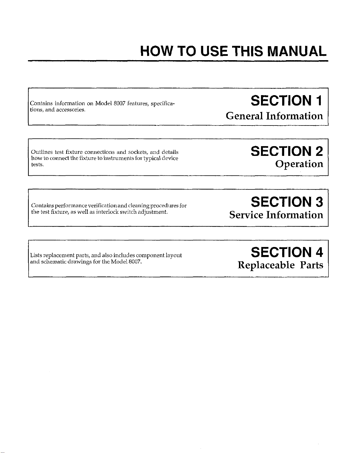
HOW TO USE THIS MANUAL
Contains information on Model 8007 features, specifications, and accessories.
Outlines test fixture connections and sockets, and details
how to connect the fixture to instruments for typical device
tests.
Contains performance verification and cleaning procedures for
the test fixture, as well as interlock switch adjustment.
Lists replacement parts, and also includes component layout
and schematic drawings for the Model 8007.
SECTION 1
General Information
SECTION 2
Operation
SECTION 3
Service Information
SECTION 4
Replaceable Parts
Page 11

Table of Contents
SECTION 1 - General Information
1.1 INTRODUCTION
1.2 FEATURES .
1.3 WARRANTY INFORMATION
1.4 MANUAL ADDENDA
1.5 SAFETY SYMBOLS AND TERMS
1.6
1.7 UNPACKING AND INSPECTION
1.7.1
1.72 Shipment Contents
1.7.3
1.8 REPACKING FOR SHIPMENT
1.9
SECTION 2 - Operation
SPECIFICATIONS
Inspection for Damage
Instruction Manual
OPTIONAL ACCESSORIES
2.1
2.2
2.2.1
2.2.2
2.2.3
2.3
2.4
2.4.1
2.4.2
2.4.3
2.4.4
2.4.5
2.5
2.5.1
2.5.2
2.5.3
2.54
2.5.5
2.5.6
2.57
2.5.8
2.5.9
2.5.10
2.5.11
2.5.12
2.5.13
2.5.14
2.5.15
INTRODUCTION
FIXTURE CONFIGURATION
RearPanel .......................
Front Panel. ......................
Sub Chassis Guarding
MATRIXCARDCONNECTIONS ......................................................
TYPICAL INSTRUMENT CONNECTIONS
Adapters
Source Measure Unit
DMM (Digital Multimeter)
Electrometer
SourceConnections
MEASUREMENT CONSIDERATIONS
Path Isolation
Keeping Connectors and Sockets Clean
Shielding
Guarding .......................................................................... 2-18
CableNoiseCurrents
MagneticFields
RadioFrequencyInterference
GroundLoops .....................................................................
Capacitance Considerations
Device Oscillation
Environmental Considerations
Vibration
Low Current and Low Voltage Measurements
Cumulative Power
AC Measurements
..........................................................................
..........................................................................
..........................................................................
..................
........
............................................................... 2-6
................................................................
...........................................................
.......................................................................
.................................................................
......................................................................
...............................................................
....................................................................
........................................................
..........................................................
..................................................................
.......................................................
..................................................................
.................................................................. 2-24
................................................. 2-l
.................................................
.................................................
.................................................
..............................................
..................................................
................................................
..........................................
2-1
2-l
2-5
2-7
2-7
2-9
2-11
2-11
2-14
2-14
2.17
2-17
2-18
2-18
2-20
2-20
2-21
2-21
2-22
2-22
2-24
2-24
2-24
2-24
Page 12

2.6
2.6.1
2.6.2
2.6.3
2.7
2.7.1
2.7.2
2.7.3
2.7.4
2.7.5
TYPICAL APPLICATIONS ...............................
CVMeasurements .....................................
FETTesting ...........................................
Semiconductor Parameter Analysis
USING THE I’ROTOTYPING BOARD
Board Wiring .........................................
Board Cleaning .......................................
Board Installation .....................................
Prototyping Board Considerations
Wiring Kelvin Connections on the Prototyping Board
SECTION 3 - Service Information
......................
.....................
.......................
......
..........
..........
.......... 2-28
..........
.......... 2-31
.......... 2-31
.......... 2-31
.......... 2-32
.......... 2-32
..........
2-25
2-25
2-29
2-32
3.1
3.2
3.2.1
3.2.2
3.2.3
3.2.4
3.2.5
3.2.6
3.2.7
3.3
3.3.1
3.3.2
3.4
3.4.1
3.4.2
3.5
3.6
3.7
3.7.1
3.7.2
3.7.3
3.7.4
INTRODUCTION ............................
PERFORMANCE VERIFICATION ..............
Environmental Conditions ...................
Recommended Test Equipment. ..............
Performance Record ........................
Isolation Resistance Verification ..............
Offset Current Verification ...................
Path Resistance Verification ..................
ACPerformance ...........................
HANDLING AND CLEANING PRECAUTIONS
Board Handling and Cleaning ................
Connector Cleaning. ........................
DISASSEMBLY ..............................
Fixture Disassembly ........................
Sub Chassis Disassembly ....................
INTERLOCK SWITCH CALIBRATION
PATHWAY MODIFICATION ..................
BINDING POST INSTALLATION ..............
Supplied Binding Posts ......................
Installation Procedure .......................
Binding Post Wiring ........................
Sub Chassis Installation .....................
.........
......
...... 3-1
......
...... 3-1
...... 3-2
...... 3-2
...... 3-4
...... 3-5
......
...... 3-7
...... 3-8
...... 3-8
......
......
...... 3-9
......
......
...... 3-11
......
...... 3-12
...... 3-12
...... 3-12
3-1
3-1
3-6
3-8
3-8
3-9
3-10
3-11
SECTION 4 - Replaceable Parts
4.1
4.2
4.3
4.4
4.5
INTRODUCTION .............................................................
PARTS LIST ..................................................................
ORDERING INFORMATION ...................................................
FACTORY SERVICE ...........................................................
COMPONENT LAYOUT AND SCHEMATIC DIAGRAM
...........................
...... 4-1
...... 4-l
......
...... 4-1
...... 4-1
4-1
Page 13

SECTION 2 - Operation
List of Illustrations
Figure 2-l
Figure 2-2
Figure 2-3
Figure 2-4
Figure 2-5
Figure 2-6
Figure 2-7
Figure 2-8
Figure 2-9
Figure 2-10
Figure 2-11
Figure 2-12
Figure 2-13
Figure 2-14
Figure 2-15
Figure 2-16
Figure 2-17
Figure 2-18
Figure 2-19
Figure 2-20
Figure 2-21
Figure 2-22
Figure 2-23
Figure 2-24
Figure 2-25
Figure 2-26
Figure 2-27
Figure 2-28 Typical Common-Source FET IV Characteristics
Figure 2-29
Figure 2-30
Figure 2-31
Figure 2-32
Figure 2-33
Figure 2-34
Model8007RearPanel ............................................................
Safety Interlock Connections
Input/OutputEquivalentCircuit ...................................................
Front Panel ......................................................................
Example of Sub Chassis Guarding
Matrix Card Connection Example
Adapters Required for Connections
Source Measure Unit Connections
DMMConnections ...............................................................
Electrometer Connections
Voltage Source Connections
Current Source Connections
Path Isolation Resistance
Voltage Attenuation by Path Isolation Resistance
ShieldingExample ................................................................
GuardedCircuit ..................................................................
Typical Guarded Signal Connections
Power Line GroundLoops .........................................................
Eliminating Ground Loops
5pe #73 Material, Impedance vs. Frequency
Type #43 Material, Impedance vs. Frequency Without Leads.
Type #43 Material, Impedance vs. Frequency With Leads.
CVTestSystem ..................................................................
Typical High Frequency CV Curve Generated by Model 590
Typical Quasistatic CV Curve Generated by Model 595
FETTestSystem ..................................................................
System Connections for JFET Test
Semiconductor Parameter Analysis Switching System
Current Gain Test Configuration
Prototyping Board ................................................................
PrototypingBoardInstallation .....................................................
KelvinConnections ...............................................................
Using Socket Jumpering to Add Kelvin Connections
.......................................................
..................................................
..................................................
................................................. 2-10
..................................................
.........................................................
........................................................
.......................................................
.......................................................... 2-17
................................................
........................................................
.........................................
...................................................
....................................................
.....................................
...........................
..............................
...........................
................................
......................................
.................................
..................................
2-2
2-3
2-5
2-6
2-7
2-8
2-12
2-13
2-14
2-15
2-16
2-18
2-19
2-19
2-20
2-21
2-21
2-23
2-23
2-23
2-25
2-26
2-27
2-28
2-29
2-29
2-30
2-31
2-32
2-33
2-33
2-33
Page 14

SECTION 3 - Service Information
Figure 3-l
Figure 3-2
Figure 33
Figure 3-4
Figure 3-5
Figure 3-6
Figure 3-7
Figure 3-8
Figure 3-9
Figure 3-10
Figure 3-11
Path Isolation Verification Connections
Offset Current Verification Connections
Path Resistance Verification Connections
Connections for AC Response Tests
Sub Chassis Removal ...................
Fixture Assembly .......................
Sub Chassis Disassembly ................
Hinge Alignment .......................
Safety Interlock Switch Adjustment
Examples of Pathway Modification
Binding Post Installation ................
.......
.......
.......
....
...
............
............
............ 3-6
............ 3-7
............ 3-8
............ 3-9
............
............ 3-10
............ 3-10
............ 3-11
............
3-4
3-5
3-9
3-12
Page 15
SECTION 2 - Operation
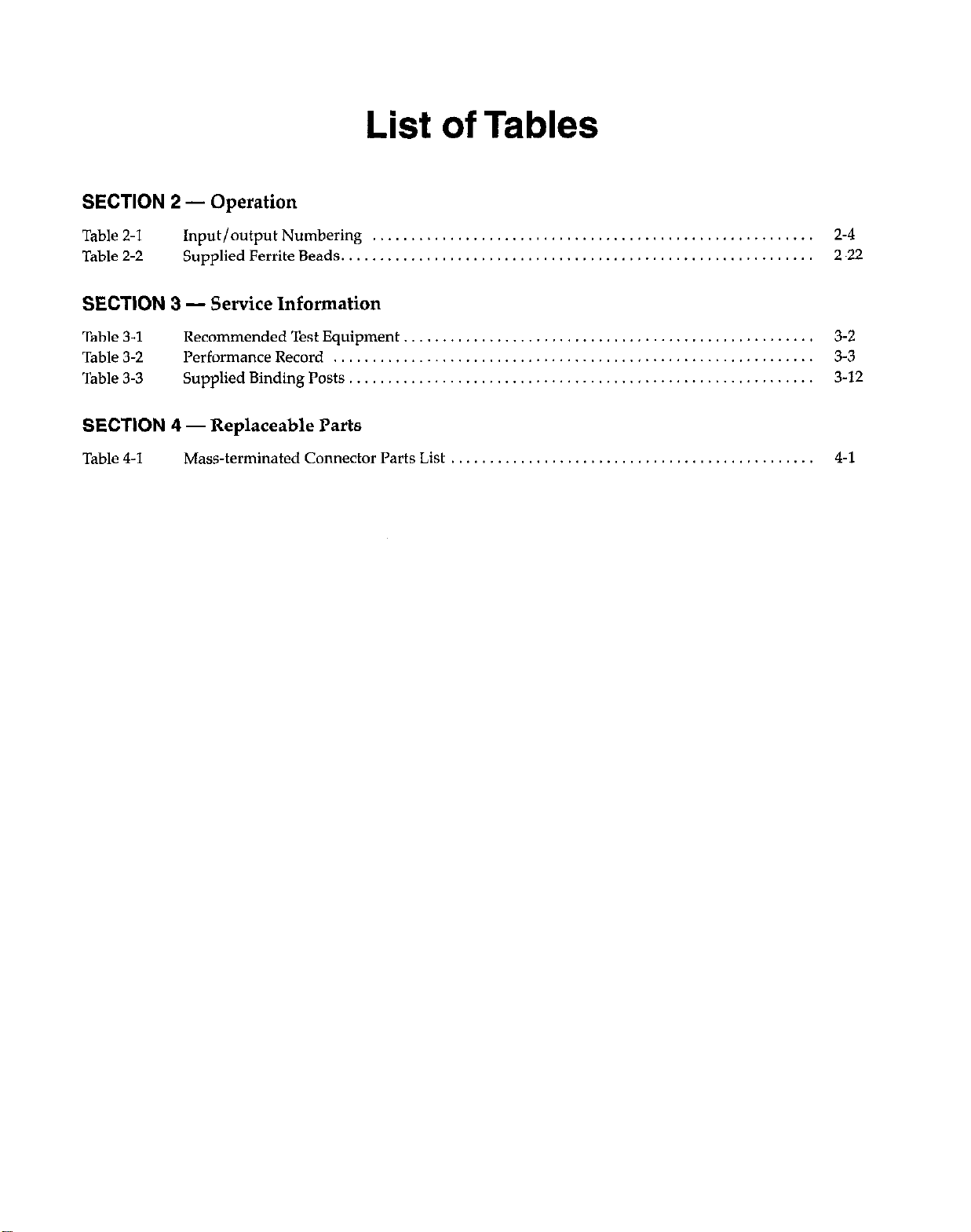
List of Tables
Table 2-l
Table 2-2
Input/output Numbering
Supplied Ferrite Beads.
SECTION 3 - Service Information
Table 3-1
Table 3-2
Table 3-3
Recommended Test Equipment
Performance Record
Supplied Binding Posts ......................
........................
SECTION 4 - Replaceable Parts
Table 4-l
Mass-terminated Connector Parts List
...............
2-4
2-22
......
......
...... 3-12
3-2
3-3
Page 16

Page 17

SECTION 1
General Information
1.1 INTRODUCTION
This section contains general information about the
Model 8007 Semiconductor Test Fixture, and it is arranged in the following manner:
1.2 Features
1.3 Warranty Information
1.4 Manual Addenda
1.5 Safety Symbols and Terms
1.6 Specifications
.
IHinged seamless lid for light-tight and Shielded measurements.
.
Interlocked lid for safety.
1.3 WARRANTY INFORMATION
Warranty information is located on the inside front cover
of this instruction manual. Should your Model 8007 require warranty service, contact the I<eithley representative or authorized repair facility in your area for further
information. When returning the fixture for repair, be
sure to fill out and include the service form at the back of
this manual in order to provide the repair facility with the
necessary information.
1.7 Unpacking and Inspection
1.8 Repacking for Shipment
1.9 Optional Accessories
1.2 FEATURES
The Model 8007 Semiconductor Test Fixture provides a
convenient way to connect the Model 7072 Semiconductor Matrix Card to standard packaged semiconductor devices. The Model 8007 has two ZIF (zero insertion force)
sockets to simplify connections to a variety of devices.
Key features of the Model 8007 include:
Six mass-terminated connectors located on the rear
panel for connecting the fixture to the Model 7072 matrix card or other devices.
24.pin and 48-pin ZIF sockets for ease of connections
to a variety of DIP packaged devices from 0.3” to 0.6”
lead centers.
Prototyping board, which plugs into the ZIF sockets,
can be used for custom circuit wiring.
Guarding pathways are carried through to the ZIF
socket terminals in order to maintain maximum pathway isolation.
1.4 MANUAL ADDENDA
Any improvements or changes concerning the test fixture or manual will be explained in an addendum included with the the unit. Be sure to note these changes
and incorporate them ilvto the manual before using or
servicing the fixture.
1.5 SAFETY SYMBOLS AND TERMS
The following symbols and terms may be found on an in-
strument or used in this manual.
The A
should refer to the operating instructions located in the
instruction manual.
The = symbol represents a protective grounding terminal. This terminal must be connected to a safety earth
ground via #18 AWG minimum wire before operation.
The WARNING heading used in this manual explains
dangers that might result in personal injury or death. Always read the associated information very carefully be-
fore performing the indicated procedure.
symbol on an instrument indicates that the user
0
l-1
Page 18

SECTION 1
GeneralInformation
The CAUTION heading used in this manual explains
hazards that could damage the unit. Such damage may
invalidate the warranty.
1.6 SPECIFICATIONS
Model 8007 specifications may be found at the front of
this manual.
1.7 UNPACKING AND INSPECTION
1.7.1
Upon receiving the Model 8007, carefully unpack it from
its shipping carton and inspect the fixture for any obvious signs of physical damage. Report any such damage to
the shipping agent immediately. Save the original packing carton for possible future reshipment.
1.7.2
The following items are included with every Model 8007
order:
.
Model 8007 Semiconductor Test Fixture
.
Model 8007~PTB prototyping board
.
Two Model 8007-MTC-3 mass-terminated triax cable
assemblies
.
Safety grounding cable (Model 8007-GND-3)
.
Safety interlock cable (Model 236~ILC-3)
.
Five 5-way binding posts
.
24 ferrite beads for device oscillation control (see para-
graph 2.5.10).
.
Model 8007 Instruction Manual
.
Additional accessories as ordered
1
7.3
If an additional instruction manual is required, order the
manual package, Keithley part number 8007-901-00. The
manual package includes an instruction manual and any
pertinent addenda.
Inspection for Damage
Shipment Contents
Instruction Manual
1.8 REPACKING FOR SHIPMENT
Should it become necessary to return the Model 8007 for
repair, carefully pack the unit in its original packing carton or the equivalent, and include the following information:
Advise as to the wwranty status of the test fixture.
Write ATTENTION REPAIR DEPARTMENT on the
shipping label.
Fill out and include the service form located at theback
of this manual.
1.9 OPTIONAL ACCESSORIES
Model 236ILC-3 Interlock Cable: The Model 236.ILC-3
is 3m (10 ft.) in length and is intended to connect the
Model 8007 interlock to instruments with similar inter-
lock circuits such as the Model 236 and 237 Source Meas-
ure Units.
Model 8007-MTC-3 Triax Cable Assembly: The Model
8007.MTC-3 is intended for input/output connections to
the Model 8007. The Model 8007-MTC-3 has hyelve
3.meter (lo-foot) triaxial cables that terminate to a single
mass-terminated connector on one end, and each cable is
terminated with a male triax connector on the other end.
A total of six Model 8007-MTC-3 cable assemblies are required to use all 72 input/output pathways on the test
fixture.
Model 8007-PTB Prototyping Board: The Model
8007~PTB Prototyping board is the board supplied with
the Model 8007. Additional Model 8007-FTB boards may
be ordered to allow ease of changing test circuits. The
prototyping board contains breadboarding areas with
holes on standard 0.1” centers, 0.04” in diameter for easy
mounting of standard components such as ICs, transistors, diodes, resistors, and capacitors. The Model
8007-PTB plugs into the two ZIF sockets located on the
top panel of the test fixture. The prototypingboard canbe
secured to the top panel with the captive screw, if desired, or it can be left unsecured for ease of removal.
l-2
Page 19
SECTION 2
Operation
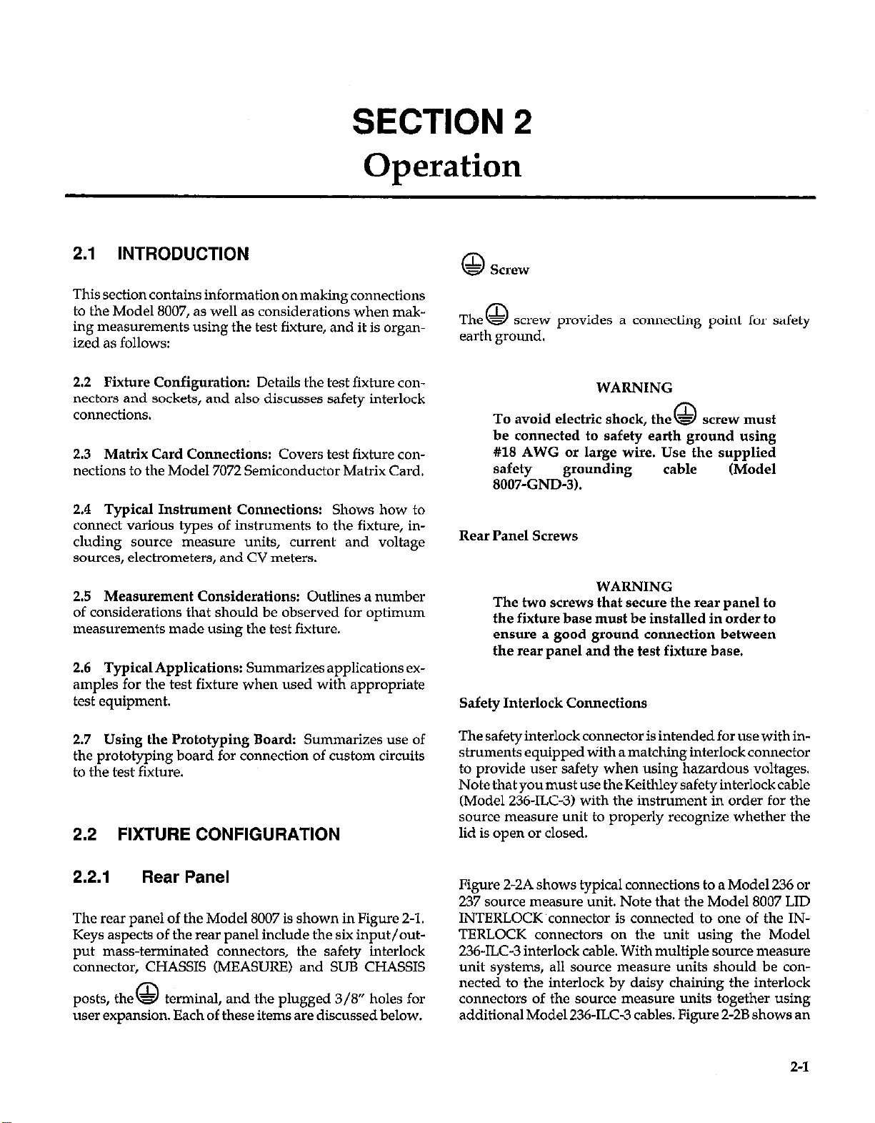
2.1 INTRODUCTION
This section contains information on making connections
to the Model 8007, as well as considerations when making measurements using the test fixture, and it is organized as follows:
Fixture Configuration: Details the test fixture con-
2.2
nectors and sockets, and also discusses safety interlock
connections.
Matrix Card Connections: Covers test fixture con-
2.3
nections to the Model 7072 Semiconductor Matrix Card.
2.4 Typical Instrument Connections: Shows how to
connect various types of instruments to the fixture, including source measure units, current and voltage
sources, electrometers, and CV meters.
2.5 Measurement Considerations: Outlines a number
of considerations that should be observed for optimum
measurements made using the test fixture.
2.6 TypicalApplications: Summarizesapplicationsexamples for the test fixture when used with appropriate
test equipment.
@
SCP3V
The = screw provides a connecting point for safety
0
earth ground.
WARNING
To avoid electric shock, the = screw must
be connected to safety earth ground using
#I18 AWG or large wire. Use the supplied
safety
8007-GND-3).
Rear Panel Screws
The two screws that secure the rear panel to
the fixture base must be installed in order to
ensure a good ground connection between
the rear panel and the test fixture base.
Safety Interlock Connections
grounding
WARNING
0
cable (Model
2.7 Using the Prototyping Board: Summarizes use of
the prototyping board for connection of custom circuits
to the test fixture.
2.2 FIXTURE CONFIGURATION
2.2.1
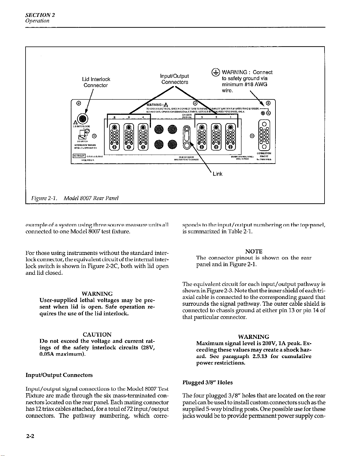
The rear panel of the Model 8007 is shown in Figure 2-1.
Keys aspects of the rear panel include the six input/output mass-terminated connectors, the safety interlock
connector, CHASSIS (MEASURE) and SUB CHASSIS
posts, the - ternmal, and the plugged 3/8” holes for 0
user expansion. Each of these items are discussed below.
Rear Panel
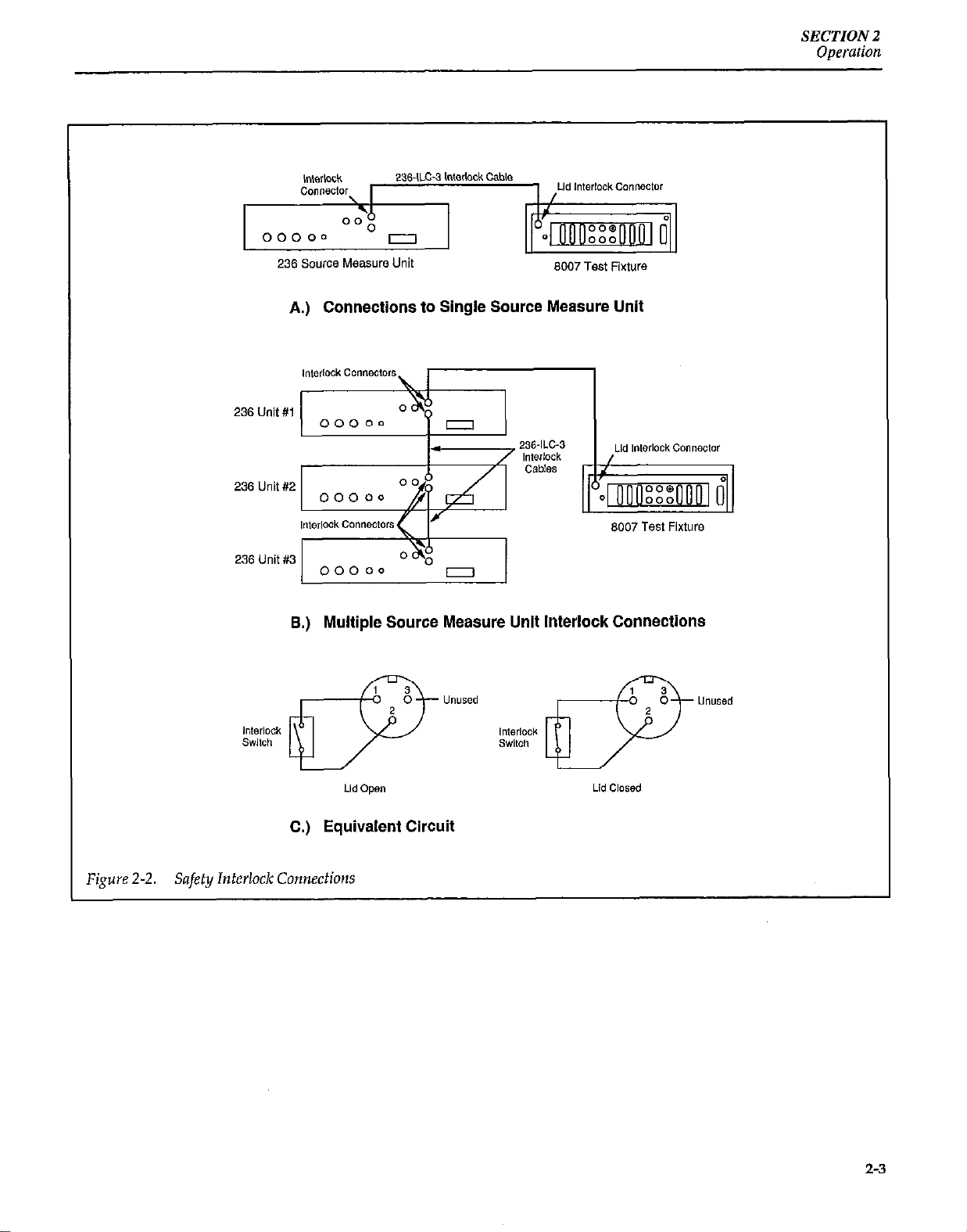
Thesafetyinterlockconnectorisintendedforusewithinstruments equipped tiith a matching interlock connector
to provide user safety when using hazardous voltages.
Note that you must use the Keithley safety interlock cable
(Model 236~ILC-3) with the instrument in order for the
source measure unit to properly recognize whether the
lid is open or closed.
Figure 2-2A shows typical connections to a Model 236 or
237 source measure unit. Note that the Model 8007 LID
INTERLOCK connector is connected to one of the INTERLOCK connectors on the unit using the Model
236-ILC-3 interlock cable. With multiple source measure
unit systems, all source measure units should be connected to the interlock by daisy chaining the interlock
connectors of the source measure units together using
additional Model 236~ILC-3 cables. Figure 2-2B shows an
2-l
Page 20
SECTION 2
Operation
Lid Interlock
connector
Figure 2-l. Model 8007 Rear Panel
InputJOutput
Connectors
example of a system using three source measure units all
connected to one Model 8007 test fixture.
minimum #18 AWG
’ Link
sponds to the input/output numbering on the top panel,
is summarized in Table 2-l.
For those using instruments without the standard interlock connector, the equivalent circuit of the internal interlock switch is shown in Figure Z-X, both with lid open
and lid closed.
WARNING
User-supplied lethal voltages may be pmsent when lid is open. Safe operation requires the use of the lid interlock.
CAUTION
Do not exceed the voltage and current ratings of the safety interlock circuits (28V,
0.05A maximum).
Input/Output Connectors
Input/output signal connections to the Model 8007 Test
Fixture are made through the six mass-terminated connectors located on the rear panel. Each mating connector
has 12 trim cables attached, for a total of 72 input/output
connectors. The pathway numbering, which corre-
NOTE
The connector pinout is shown on the rear
panel and in Figure 2-l.
The equivalent circuit for each input/output pathway is
shown in Figure 2-3. Note that the inner shield of each triaxial cable is connected to the corresponding guard that
surrounds the signal pathway. The outer cable shield is
connected to chassis ground at either pin 13 or pin 14 of
that particular connector.
WARNING
Maximum signal level is 2OOV, 1A peak. Exceeding these values may create a shock hazard. See paragraph 2.5.13 for cumulative
power restrictions.
Plugged 3/8” Holes
The four plugged 3/8” holes that are located on the rear
panel can be used to install custom connectors such as the
supplied 5-way binding posts. One possible use for these
jacks would be to provide permanent power supply con-
2-2
Page 21
SECTION 2
Operation
236 Source Measure Unit
8007 Test Fixture
A.) Connections to Single Source Measure Unit
B.) Multiple Source Measure Unit Interlock Connections
Figure 2-2.
I
Lid open
C.) Equivalent Circuit
Safety Interlock Connections
2-3
Page 22

SECTION 2
Operation
Table 2-1. Input/output Numbering
Connector Connector Pin Socket Pin Connector
Number Number Number* Number
1
1
4 1
2
3
4
5
6
7
8
9
10
11
12
2
6
7
8
9
10
11
12
13
5
14
15
16
17
6
7
8
18
19
20
9 21
10 22
11 23
24
ConnectorPin Socket Pin
Number Number*
37
2
3
4
38
39
40
41
:
7
8
9
10
11
12
42
43
44
45
46
47
48
1 1
2 2
3 3
4 4
5 5
6
7
6
7
8 8
9 9
10 10
11 11
12 12
3
25
26
27
28
29
30
7
31
8 32
9
10
11
12
33
34
35
36
6
1
2
3
4
5
6
7
8
9
10
11
12
13
14
15
16
17
18
19
20
21
22
23
24
2-4
Page 23

SECTION 2
Operation
Figure
Rp = Path Resistance
Cl, RI = Path Isolation (See specilications)
See paragraph 2.5 for discussion
-1
2-3.
Input/Output Equivalent Circuit
L----------------A
1
Coax Connection
,-- Guard Trace on PC Board
Chassis
Shorting
Link
I
8007 Test Fixture
nections to the two DIP sockets without having to route
power through the trim cables. Refer to paragraph 3.7 for
details on installing binding posts,
SUB CHASSIS Post
The SUB CHASSIS post is intended for applying a guard
signal from an external measuring or sourcing instmment. SUB CHASSIS is internally connected to the sub
chassis that houses the circuit board.
WARNING
Do not exceed the ZOOV peak between SUB
CHASSIS and CHASSIS. When using any
binding post with hazardous voltages (>3OV
RMS), shut off all sxnces beforeconnecting,
and dress all leads 80 that no conductive SUP
faces are exposed.
NOTE
The shorting link that connects SUB CHASSIS
to CHASSIS (MEASURE) should be discon-
nected from SUB CHASSIS when a guard signal is to be connected.
cmws (MEASURE) Post
The CHASSIS (MEASURE) binding post provides a convenient connecting point to fixture SUB CHASSIS. Normally, a shorting link is installed between this post and
the SUB CHASSIS binding post, which places the sub
chassis at chassis (earth) ground as well. If you intend to
connect a guard signal or circuit LO, the shorting link
must be removed from SUB CHASSIS.
WARNING
Do not use cmss~s (MEASURE) for safety
earth ground.
2.2.2
The front panel contains the 24-pin and 4%pin ZIF (zero
insertion force) sockets for device connections
(Figure Z-4). These two sockets can accommodate a variety of different DIP packages such as 14; 16-, and IS-pin
DIPS with 0.3 to 0.6.inch spacing. Also, the prototyping
board, which is covered in paragraph 2.7, is designed to
plug into these two sockets.
The sockets are individually numbered according to
standard DIP convention (l-24 and l-48). Table 2-1 sum-
Front Panel
2-S
Page 24

CABLE NUMBER
I
CABLE NUMBER
1 2 5
WARNING
User-supplied lethal voltages may be present while the lid is open. Safe operation requires the use of the safety interlock (paragraph 2.2.1,).
2.2.3
3
Sub Chassis Guarding
To install a device in one of the sockets, simply lift the
lever to open the socket holes, then carefully slide the
pins of tlw device down into the socket. When the device
is seated, move the socket lever down to the closed posilion to lock the d&cc into place.
2-6
NOTE
Disconnect tlw shorting link connecting SUB
CIHASSIS to CHASSIS (MEASURE) b&m
applying guard. To do so, loosen the binding
Page 25

posts, then swivel the link aside and tighten
the CHASSIS (MEASURE) binding post.
mainframe willresult in thesame 72.pin test capability as
the Model 8007 test fixture.
In order to be most effective, guard should be driven at
the same dc potential as the most critical (lowest level)
pathway to be guarded. If no guard is available, SUB
CHASSIS can be connected to circuit LO for effective
shielding of all pathways in the test fixture.
WARNING
Do not exceed the maximum recommended
SUB CHASSIS voltage (ZOOV peak).
NOTE
To avoid possible noise pickup, always cow
nect SUB CHASSIS either to guard, LO, or
CHASSIS (MEASURE).
2.3 MATRIX CARD CONNECTIONS
Model 7072 Connections
The Model 8007 is intended primarily for use with the
Model 7072 Semiconductor Matrix Card. The mass-terminated trim cable assemblies should be used to connect
the test fixture to the matrix card. Figure 2-6(A) shows an
example of how to connect the test fixture to one matrix
card. Since each Model 8007 I/O connector has connections for 12 pathways, the most logical scheme would be
to connect the test fixhm to’the columns on the Model
7072.
For additional switching pathways, additional matrix
cards must be used. SixModel 7072 cards installed in one
When making connections, keep in mind that all rows on
the Model 7072 are not the same. Rows A and B are lowcurrent rows, rows C through F are general-purpose
rows, and rows G and Hare CV rows. See the Model 7072
Instruction Manual for complete details.
Model 7152 Low-Current Matrix Card
Typical connections to a Keithley Model 7152 Low-Current Matrix Card are shown in Figure 2-6(B). Each cable
on the Model 8007-MTC-3 cable is connected to a cable on
the Model 7152-T cable using Pomona Model 5278 fe-
male-to-female trim adapters.
Model 7073 Coaxial Matrix Card
Figure 2-6(C) shows typical connections to a Model 7073
Coaxial Matrix Card. Note that each cable on the Model
8007.MTC-3 cable is connected to a BNC jack on the ma-
trix card using Pomona Model 5299 3-Q triax to BNC
adapters.
2.4 TYPICAL INSTRUMENT
CONNECTIONS
The following paragraphs show how to connect the
Model 8007 to various types of instruments through a
Model 7072 Semiconductor Matrix Card. For detailed information on cabling for matrix card-to-instrumelIt con-
nections, refer to the Model 7072 Instruction Manual, as
well as the test instrument’s instruction manual.
2-7
Page 26

SECTION 2
O/leratiorl
1
Instrument
Connections
(7078.TRX Triax)
Instrument
Connections
/----.
Mode, 8007.MTC-3 Mass-
-
7072 Semiconductor
Matrix Card
Terminated Triax Cable
A. 7072 Matrix Card Connection Example
Matrix to Triax
Cable
B. 7152 Matrix Card Example
Firwe 2-6. Matrix Cnrd Connection Exnmple
2-8
5278
Female to Female
Triax adapters
Page 27

Instrument
Connections
(7051 Coax)
SECTION 2
Opemion
7073 Coaxial
Matrix Card
C. 7073 Coaxial Matrix Card Example
Matrix Card Connection Example (Cont.)
2.4.1
In some cases, special adapters will be necessary to connect the Model 8007-MTC-3 trim cables to the instruments. Figure 2-7 shows typical connecting schemes for
Adapters
Terminated Triax Cable
trim to banana, trim cable to trim cable, 3-slot trim to
Z-lug triax, and trim to BNC connectors.
NOTE
For some connections, no commercial adapters are available. In those cases, it will be necessary to construct custom cables.
2-9
Page 28

SECTION 2
Operation
b.
BSla”a BNC/Banana
Jack
0”
ln*t,lmle”t
,,,;L; wm,..-.-D + To 8007
0 m ,,...,...,..,..... D
(Pomona 1894)
A.) TriaxiBanana
Z-Lug
Triax Adapter
,nstPunment
B.) 3-Lug Triax to Z-Lug Triax
3 Lug Triaxi BNC Triax Cable
(Pomona 5299) (8007 MTC-3)
6172
Triax
Cable
8007.MTC-3
Triax Cable
Pomona
5278
Female-to
Female Adapter
8007.MTC~3
Triax Cable
3 TO 8007
Fipre 2.7. Rdapkrs Required
C.) Triax Cable to Triax Cable
BNC Pomona
,r,,ttk,, Tg39h$ Triax Cab’e
D.) Triax to BNC
for
Connections
8007.MTC-3
Z-10
Page 29

SECTION 2
Operarion
2.4.2
Typical connections for a source measure unit are shown
in Figure 2-8. Note that the unit is connected to the rows,
while the test fixture itself is connected to the columns.
The mass-terminated triaxial cables are used to make the
connections between the test fixture and the matrix card,
while conventional trim cables should be used for connections between the unit and the matrix card.
Remote Sensing
The connections shown in Figure Z-8A are intended for
use with the source measure unit in remote sensing
mode. Remote sensing should be used when voltage
drops across the test leads and connectors are a consideration. When using remote sensing, it will be necessary
to connect two pathways to each side of the DUT. Either
but and jumper the circuit board, wire-up the prototyping board for Kelvin connections (as covered in para-
Source Measure Unit
NOTE
With some devices you may encounter device
oscillation resulting in incorrect readings. See
paragraph 2.5.10 for ways to verify the presence of oscillations and methods to minimize
them.
graph 2.7), or install short jumper wires between socket
terminals.
Local sensing
The connections shown in Figure Z-8B should be used
with the source measure unit in the local sensing mode.
Note that only two pathways are necessary through the
matrix card and test fixture to the DUT; no test fixture
modifications are necessary to use local sensing.
2.4.3
Typical connections for a DMM (for example, a Model
199) are shown in Figure 2-9. Two-wire connections are
shown in Figure 2-9(A), and 4-wire connections are
shown in Figure 2-9(B).
DMM (Digital Multimeter)
NOTE
As with source measure unit connections, the
4-wire connections will require adjacent
socket terminal jumpering or special
prototyping board wiring (paragraph 2.7) so
that two pathways are connected to each side
of the DUT.
2-11
Page 30

SECTION2
Operation
In7
I
I
! I
I !
8. Local Sensing
Page 31

SECTION 2
Opemtinn
L----J
707*
A. Z-Wire
I
L----i
Columns
8007
r----
I
1
Fipre 2-9. DMM
Connections
L----J L----.-J
7072
6. 4.Wire
8007
1
2-13
Page 32

SECTION 2
Oper&m
2.4.4
Electrometer 2.4.5 Source Connections
Two examples of electronwter connections are s11ow11 in
Figure Z-10. Guarded and unguarded volts connections
are shown in Figure 2-10(A) and Figure Z-lo(B), fast cur-
rent connections are shown in Figure Z-IO(C), and
guarded resistance connections are
shown in
Figure 2-10(D).
7072
A.) Electrometer, Unguarded Volts
Typical voltage and current source connections are
shown in Figure Z-11 and Figure 2-12 respectively. Voltage source connections are typically unguarded, while
current source connections are shown guarded, which is
the preferred configuration for low-level currents.
Coiwnns
r----
1
6.) Electrometer, Guarded Volts
7072
Columns
r----
L----J
1
0007
2-14
Page 33

r----
SECTION 2
Opemtion
C.) Electrometer, Fast Current
D.) Electrometer, Resistance (Guarded)
Electrometer Connections (Cont.)
ROW
Rows
r----7
,072
7072
COl”m”S
Columns
L----_1
r----
r----
I
8007
1
1
I
Figure 2-l 1. Voltage Source Connections
:- -) DUT
L- -.
fi
--
1
I
I
I
I
I
I
A--
l
-Socket
2-15
Page 34

SECTION 2
Operation
A,) Current Source, Unguarded
L----J
7072
Columns
Columns
r----
L----
r----
8007
1
I
I
I
I
I
I
I
6.) Current Source, Guarded
Figure Z-12. Current Source Connections
I Socket
I
I
_I
2-16
Page 35

SECTION 2
Operation
2.5 MEASUREMENT CONSIDERATIONS
Many measurements made with the Model 8007 can be
affected by noise and leakage paths. The following paragraphs discuss possible problems that might affect these
measurements and ways to minimize their effects.
2.5.1 Path Isolation
The path isolation is simply the equivalent impedance
between any two test paths in a measurement system.
Ideally, the path isolation should be infinite, but the actual resistance and distributed capacitance of cables, connectors, and sockets results in less than infinite path isolation values for these devices.
Path isolation resistance forms a signal path that is in parallel with the equivalent resistance of the DUT, as shown
in Figure Z-13. For low-to-medium device resistance values, path isolation resistance is seldom a consideration;
however, it can seriously degrade measurement accuracy when testing high-impedance devices. The voltage
measured across such a device, for example, can be substantially attenuated by the voltage divider action of the
device source resistance and path isolation resistance, as
shown in Figure 2-14. Also, leakage currents can be gen-
erated through these resistances by voltage sources in the
system.
Any distributed capacitance between measurement
pathways affects dc measurement settling time as well as
ac measurement accuracy. Thus, it is important that such
capacitance be kept as low as possible. Although the distributed capacitance of the test fixture and switching matrix card is generally fixed by design, there is one area
where you do have control over the capacitance in your
test system: the connecting cables. Use only low-capacitance cabling, and keep all cables as short as possible.
The effects of path resistance and capacitance can be
minimized by using guarding whenever possible. Paragraph 2.5.4 discusses guarding in more detail.
r-----
I
I I
I
I I
I
I __
RDUT
1
1 =E~ur
I I
I
L------l
DUT
RDUT
EDLIT
R PATH
= Source resistance of DUT
= Source voltage of DUT
= Path Isolation Resistance
= Input Resistance of Measuring Instrument
RIN
I
I
I RPATH <:
I
<
I
I
RIN <;
<
Measuring
Instrument
Figure 2-13. Path Isolation Resistance
2-17
Page 36

any semiconductor test system. Otherwise, interference
from such noise sources as line frequency and RF fields
can seriously corrupt a measurement.
-L-
- EDUT
T
2.5.2
As is the case with any hi@-resistance device, the integrity of connectors and sockets cm be compromised if they
are not handled properly. If the insulation becomes con-
taminated, the path isolation resistance will be substan-
tially reduced, nffcctillgl~igh-impedance measurements.
Oils and salts from the skin can contaminate insulators,
reducing their resistance. Also, contaminants present in
the air can be deposited on the insulator surfaces. To
avoid thcsc problems, never touch the connector or socket insulating material. In addition, the test fixture should
be used only in clean, dry environments to avoid con-
tamination.
Keeping Connectors and Sockets
Clean
For unguarded measurements, the inner shield of the triaxial cable that surrounds the signal path should be cow
netted to signal LO (or chassis ground for instruments
without isolated LO terminals). An example of how to
maintain a shielded pathway from an instrument,
through the matrix card, to the test fixture is shown in
Figure Z-15.
2.5.4
Guarding is important in high-impedance,circlLlts where
leakage resistance and capacitance coulli havedegrading
effects on the measurement. Guarding consists of using a
shield surrounding a conductor that is carrying the highimpedance signal. This shield is driven by a low-impedance amplifier to maintain the shield at signal potential.
For triaxial cables, the inner shield is used as guard. With
the Model 8007 test fixture, cach~guad p&way is carried through as close as possible to the corres~ponding device socket pin.
Guarding minimizes leakage resistance effects by driving the inner cable shield with a unity-gain amplifier, as
shown in Figure Z-16. Since the amplifier has a high input
impedance, it minimizes loading on the high-impedance
signal lead. Also, the low output impedance ensures that
the shield remains at signal potential, so that virtually no
leakage current flows through the leakage resistance, RI,.
Leakage between inner and outer shields may be consid-
erable, but that leakage is of little consequence because
that current is supplied by the buffer amplifier rather
than the signal itself.
Guarding
If the connector or socket insulators should become contaminated, either by inadvertent touching, or from air-
borne deposits, they can be cleaned wit11 a cotton swab
dipped in clean methanol. After thorough cleaning, they
should be allowed to dry for several hours in a 50°C lowhumidity environment before use, or they can be dried
more quickly using dry nitrogen gas. Do not use air from
an ordinary air compressor because oil present in the air
may result in contamination.
2.5.3
Proper shielding of all signal paths and devices under
test is important to minimize noise pickup in virtually
2-18
Shielding
In a similar manner, guarding also reduces the effective
cable capacitance, resulting in much faster measure-
ments on high-impedance circuits. Because any distrib-
uted capacitance is charged through the low impedance
of the buffer amplifier rather than by the source, settling
times are shortened considerably by guarding.
In order to use individual pathway guarding effectively
wit11 the Model 8007, the inner shield of the connecting
triaxial cable carrying the HI signal pat11 should be con-
nected to the guard output of the sourcing or measuring
instrument. That guard output should be at the same dc
potential as the signal being guarded. For the LO signal
path, simply connect the inner shield to LO at the meas-
uring or sourcing instrument.
Page 37

SE‘CTION 2
Operation
Inner
inner Shield of HI Triax
Connected to LO Connected to LO
r-----------
r-----
I
l-----------d
-----
7072 Card
Triax
1
r------i
l---- _I
8007
t
Socket
Figure 2-16.
Guarded Circuit
DUT
In
Fixture
/
Inner Shield
of Triax
r-------
Measuring
Instrument
2-19
Page 38

Figure 2-17 shows typical guarded connections, with the
guard path carried through the matrix card. Guard is carried through internally to the corresponding test socket
pin in order to provide maximum guarding benefits.
The entire sub chassis can also be guarded by connecting
a suitable guard potential to the rear panel SUB CHASSIS
jack of the test fixture. If no guard is available, connect the
SUB CHASSIS jack to circuit LO at a convenient point in
order to effectively shield internal fixture pathways.
WARNING
Maximum voltage between SUB CHASSIS
and CHASSIS (MEASURE) is 2OOV peak.
friction. l’iezoelectric charges are also generated by applying pressure to the cable.
In order to minimize cable noise currents, tie down cables
to avoid flexing, and isolate the cables from vibration
sources such as motors and pumps. Also, avoid tcmpera-
ture extremes that could lead to cable expansion and con-
traction.
2.5.6 Magnetic Fields
When a conductor loop cuts through magnetic lines of
force, a very small current ,is gener@ted. ‘This phenomenon will frequently cause unwanted signals to occur in
the test leads of a test system. If the conductor has sufficient length, even weak magnetic fields like those of the
earth can create sufficient signals to affect low-level
lneasurelnellts.
2.5.5 Cable Noise Currents
Noise currents can be generated by bending or flexing the
triaxial connecting cables. These currents, which are
known as triboelectric currents, are generated by charges
created between a conductor and insulator caused by
r-----
Two ways to reduce these effects are: (1) reduce the
lengths of the connecting cables, and (2) minimize the exposed circuit area. In extreme cases, magnetic shielding
may be required. Special metal with high permeability at
low flux densities (such as mu metal) are effective at reducing these effects.
Columns
-----
Triax
1
Triax
r------l
‘igure 2-l 7.
Z-20
L----------A
7072 Card
Socket
Typical Guarded Sigmf Connections
Page 39

Even when the conductor is stationary, magnetically-induced signals may still be a problem. Fields can be produced by various signals such as the ac power line voltage. Large inductors such as power transformers can
generate substantial magnetic fields, so care must be
taken to keep the test fixture a good distance away from
these potential noise sources.
2.5.7 Radio Frequency interference
RF1 (Radio Frequency Interference) is a general term
used to describe electromagnetic interference over a
wide range of frequencies across the spectrum. Such RF1
can be particularly troublesome at low signal levels, but it
can also affect measurements at high levels if the problem
is of sufficient severity.
RFI can be caused by steady-state sources such as radio or
TV signals, or some types of electronic equipment (mi-
croprocessors, high speed digital circuits, etc.), or it can
result from impulse sources, as in the case of arcing in
high-voltage environments. In either case, the effect on
the measurement can be considerable if enough of the
unwanted signal is present.
RF1 can be minimized in several ways. The most obvious
method is to keep the test fixture and signal leads as far
away from the RFI source as possible. Additional shielding of the test fixture, signal leads, sources, and measuring~instruments will often reduce RF1 to an acceptable
level. In extreme cases, a specially-constructed screen
room may be required to sufficiently attenuate the troublesome signal.
ment LO signal leads and then back through power line
ground. This circulating current develops a small but un-
desirable voltage between the LO terminals of the two instruments. This voltage will be added to the source voltage, affecting the accuracy of the measurement.
Fiaure Z-18. Power Line Ground LOOPS
Figure 2-19 shows how to connect several instruments
together to eliminate this type of ground loop problem.
Here, only one instrument is connected to power line
ground
Many instruments incorporate internal filtering that may
help to reduce RFI effects in some situations. In Some
cases, additional external filtering may also be required.
Keep in mind, however, that filtering may have detri-
mental effects on the desired signal.
2.5.8
When two or more instruments are connected together,
care must be taken to avoid unwanted signals caused by
ground loops. Ground loops usually occur when sensi-
tive instrumentation is connected to other instrumentation with more than one signal return path such as power
line ground. As shown in Figure Z-18, the resulting
ground loop causes current to flow through the instru-
Ground Loops
Ground loops are not normally a problem with instrulnentshavingisolated LO terminals. However, allinstruments in the test setup may not be designed in this manner. When in doubt, consult the manual for all instrumentation in the test setup.
z-21
Page 40

SECTION 2
Oat-ration
2.5.9 Capacitance Considerations
When making critical low-capacitance measurements,
keep in mind that the worst (highest) capacitance performance of the test fixture is between adjacent socket
pins. To minimize the effects of socket capacitance, measure between non-adjacent socket terminals. For example, assume you wish to measure the value of a discrete
capacitor by connecting the device between socket pins.
In this case, it would be better to connect the capacitor
across the socket rather than between adjacent socket
pins.
2.5.10 Device Oscillation
In some cases, you may encounter device oscillation
that will affect your measurements. Such oscillations are
not caused by the test fixture, but they can be present if
sufficient positive feedback is present in the test system.
This feedback can be caused by such factors as the additional capacitance of the test cables.
If present at all, oscillations will be seen more often with
multiple-instrument setups (for example, with source
measure units) when testing devices with high gainbandwidth products such as RF FETs, or with negativeresistance devices such as UJTs.
Verifying the Presence of Oscillations
With dc testing, the most obvious signs of possible oscil-
lations are:
l Unrepeatable or unstable measurements
l Inconsistent readings across ranges
l Unexpected data values
l Data changing significantly with the integration rate
of the instrument
l Changes in data with added instrument filtering.
The ac response of the pathways with ferrite beads will
be reduced, although the bulk dc resistance is very low.
Note that the beads must be installed as close to the
device package as possible to be most effective. Since
these beads typically have an inductance in the pH
range or less, this solution may be useful only for higher
oscillation frequencies (above 1OMHz or so).
Supplied Ferrite Beads
As summarized in Table 2-2, a total of 24 each of three
types of ferrite beads are supplied with the Model 8007.
These beads include leadless versions of Fair-Rite
Products Corp. types #43 and #73 ferrite material. A
version of type #43 with leads is also supplied for ease
of construction.
Table 2-2. Supplied Ferrite Beads
Qty. Description Keithley Part Number
24
Type #73, leadless CH-48
24
‘Qpe #43, leadless CH-49
24
Type #43, with leads
CH-50
Installing Ferrite Beads
If oscillation is found to be a problem, install ferrite
beads in the appropriate pathways on the prototyping
board supplied with the Model 8007 (see paragraphs
2.5.10 and 2.7 of instruction manual for information on
device oscillation and details on using the prototyping
board). In most cases, best results will be obtained by
installing beads on the gate or base leads of the DUTs.
Since the effective bead impedances at the frequency of
interest are typically less than 10051 (see below), it may
be necessary to use two or more beads, particularly in
difficult cases.
If any of these symptoms are noted, the presence of
oscillations can be verified with an oscilloscope. Note,
however, that connecting an oscilloscope may affect the
oscillation, either increasing or decreasing them, or possibly even dampening them completely.
Using Ferrite Beads
Using the supplied ferrite beads may solve the oscilla-
tion problem. These ferrite beads can be permanently
installed in all pathways going to the device under test.
2-22
Suppression Capabilities
Figure Z-20 shows how the impedance of the type #73
beads varies with frequency. Note that this material is
optimized for use below 40MHz. Figures 2-21 and 2-22
show the impedance vs. frequency curve of the type #43
material with and without leads, which is optimized for
use above 40MHz, up to a maximum of 200MHz. Note
that installation of ferrite beads may have undesirable
effects on the AC frequency characteristics of the test
circuit.
Page 41

SECTION 2
Oweration
Using Resistors
Another
solution
for oscillation - one that may also be
useful at lower frequencies-is to install series resistors
in the source or emitter of the DUT in order to reduce
overall gain. Some experimentation will be necessary to
determine the optimum value. In many cases, a small
resistance value will be all that is necessary to dampen
oscillations. In more serious cases, higher values will be
required. If you do install a series resistor, keep in mind
that it may have detrimental effects on other aspects of
the measurements. Always select as small a resistance
value as possible to minimize these effects.
LC Filters
For extreme cases, small LCT filters are available. These
filters can be mounted directly on the circuit board with
the inductive elements in series with the pathway, while
the capacitance element should be placed in parallel
with the pathway. Again, installing filters will affect the
ac performance of the test fixture.
2-23
Page 42

SECTION 2
Operation
Installing Components
In order to install series components, it will be necessary
to cut the individual circuit board traces going to the
socket terminals. For maximum benefit, devices should
be installed by soldering them to the traces as close to
the socket terminals as possible. Paragraph 3.6 discusses
circuit board modification in mcwe detail. Before modifying the test fixture, you may wish to verify that the
proposed remedy is viable by constructing a test circuit
on the prototyping board (paragraph 2.7).
CAUTION
Installing components or otherwise modifying the test fixture may degrade fixture performance specifications.
2.5.11 Environmental Considerations
Cleanliness
The test fixture should be operated only in a clean envi-
ronment. Otherwise, any dust or dirt that settles on the
fixture sockets or connectors could degrade fixture specifications. Even if front panel sockets are periodically
cleaned, long-term internal dirt build-up could also
affect specifications. If such contamination is suspected.
perform the performance verification procedures outlined in Section 3. Clean all internal parts using the procedure discussed in paragraph 3.3 if contamination is
verified.
Humidity
The test fixture should be operated within the humidity
limits given in the specifications at the front of this manual. Note that current and path isolation in particular
are affected by humidity. For best results, use the fixture
in a low-humidity environment.
Light
motors and pumps. Place the test fixture on a vibrationisolating base such as rubber if vibration swrces cannot
be completely eliminated.
2.5.13 Low Current and Low Voltage
Measurements
The effects of the fixture offset current come into play
with very low currents. To minimize these effects,
enable the instrument zero or suppression feature with
no device installed in the sockets and the lid closed to
cancel the offset current. Install the device, and make
the measurement with zero or suppress enabled. Measurements should be made as soon as possible after suppression to ensure that the offset currents are properly
suppressed.
Similarly, low-voltage measurements can be affected by
thermal EMF voltages. These voltages, which are typically generated at connector and relay contact points,
can also be suppressed by using the zero feature of the
measuring instrument. However, since these offsets are
thermally generated, temperature variations will cause
their values to drift. For that reason, the fixture should
be operated in a thermally-stable environment, especially when making critical, low-voltage measurements.
Also, it will be necessary to rezero the measuring instrument often if thermal drift is noted.
2.5.14 Cumulative Power
Each signal pathway of the test fixture is rated at ZOOV,
1A peak. Since there are 72 pathways, it is obvious that
the theoretical total power that could be dissipated by
device(s) in the fixture is extremely high. Note, however, that there is a practical limit as to how much
cumulative power can be safely dissipated within the
test fixture. To avoid fixture damage, restrict cumulative
power so that the operating temperature of the fixture
does not exceed the value stated in the specifications at
the front of this manual.
Some devices are affected by light, which is the main
reason the Model 8007 is equipped with a light-tight
gasket. In order to ensure that the light-tight environment for the device is maintained, periodically check
the gasket in the base for deterioration. Also, make certain that no obstructions such as test leads keep the lid
from seating properly.
2.5.12 Vibration
Any vibration could affect fixture performance due to
piezoelechic and triboelectric effects. To obviate these
effects, keep the fixture and cables as far away as
possible from vibration-producing sources such as
2-24
CAUTION
Exceeding the recommended operating temperature may cause fixture damage.
2.5.15 AC Measurements
The equivalent ac circuit of the test fixture is especially
important to those making ac measurements. For that
reason, typical specifications for insertion loss, crosstalk,
and 3dB bandwidth are summarized at the front of this
manual. An overview of how to go about testing these
aspects of fixture performance are summarized in paragraph 3.2.7.
Page 43

SECTION 2
Operation
2.6 TYPICAL APPLICATIONS
The following paragraphs discuss several typical applications for using the Model 8007 along with the
Model 7072 Semiconductor Matrix Card.
2.6.1 CV Measurements
CV (capacitance-voltage) measurements are often made
on semiconductor devices in order to determine
important semiconductor parameters such as doping
profile, band bending, and mobile ion concentration.
The following paragraphs discuss a typical CV system
and typical CV curves.
Typical System Configuration
Figure 2-23 shows a typical system for making CV mea-
surements on a device with several elements requiring
testing. System components perform the following
functions.
8007 Test Fixture
r-----
-------
1
Model 590 CV Analyzer: Measures CV data at 1OOkHz
and 1MHz and sends the resulting data to the computer
for further analysis.
Model 595 Quasistatic CV Meter: Measures quasistatic
CV data and sends the data to the computer.
Model 707 Switching Matrix: Controls the Semiconductor Matrix Card to close and open the desired
crosspoints at the proper time.
Model 7072 Semiconductor Matrix Card: Switches the
signal pathways to the device elements under test.
Computer: Controls the instruments in the test system
using appropriate software.
HPGL Plotter: Provides hard copy graphs for the tests.
Model 8007 Test Fixture: Holds the device package
being tested and provides the interconnection interface
between the inst&ments and the device.
707 Switching Matrix o- - ’
IEEE-488 Bus
Note: Rows C-F can be used la
this signal path.
CV Analyzer
I
HP-GL
PIOtter
‘igure Z-23.
CV Test System
2-25
Page 44

SECTION 2
Otwation
Typical CV curve8
Typical CV curves generated by the Models 590 and 595
are shown in Figure 2-24 and Figure 2-25 respectively.
The quasistatic curve is almost symmetrical, while the
high-frequency curve is asymmetrical because of the
inability of the minority carriers to follow the highfrequency test signal.
frequency CV measurements using the Model 8007 Test
Fixture.
When cable correcting the test system, be sure that the
test fixture cables are connected properly and that the
test fixture lid and ZIF sockets are closed (closing the
ZIF sockets can affect stray capacitance). Also, the
device under test must be removed from the socket
when cable correction is performed. See the Model 590
CV Measurement Considerations
High-frequency CV measurements are made using a
1OOkH.z or 1MHz test signal that can be affected by the
distributed capacitance of the connecting cables and test
fixture. In order to compensate for these effects, the
Model 590 includes software cable correction algorithms to optimize measurement accuracy. Cable correc-
Instruction Manual for complete details on cable
correction.
In a similar manner, the quasistatic CV measurements
made by the Model 590 are subject to errors caused by
leakage currents in the system. In order to minimize
these errors, it may be necessary to use the corrected
capacitance feature of the Model 590: see the Model 590
tion should always be used when -making high- Instruction Manual for details.
x
e 1.27
2
u- 1.20
8
,3 1.12
8
0 1.05
- 4.99
Keithley 590: 00:00:10:500 IOOKHz Xi Fllter ---..-..--.-. Parallel
Figure 2-24. Typical High Frequency CV Curve Generated by Model 590
-
3.99 - 2.99 -1.99 .0.99 0.00 1 .oo 1.99 2.99 3.99 4.99
Bias (Volt) X lW+OO
2-26
Page 45

+0.6E-10
SECTION 2
Oaeration
+0.4E-10
Figure 2-25.
I
I
I
-005.00
Typical Quasistatic CV Curve Generated by Model 595
VOLTAGE (V)
+005.00
KEITHLEY 595
2-27
Page 46

SECTION 2
Operation
2.6.2 FETTesting
FET devices are often tested to determine such
parameters as common-source characteristics. These
characteristic curves can yield much important
information about packaged FET devices. A typical test
system and example curves are discussed below.
Test System
Figure 2-26 shows a typical system for testing FETs. The
various components in the system perform the following functions as pictured in Figure Z-27.
Model 617 Electrometer/Source: Measures I&drain current) and sources VDS (drain-source voltage).
Model 230 Voltage Source: Sources VGS (gate-source
voltage).
Model 7072 Semiconductor Matrix Card: Routes the test
signals to the particular FET under test.
Model 707 Switching Matrix: Controls the matrix card to
open or close crosspoints as required.
‘&pica1 Common-Source Characteristics
Typical common-source characteristics are shown in
Figure Z-28. Such curves are generated by setting VGS to
specific values (for example, in increments of 0.25V),
and then stepping VDS across the desired range while
measuring 1~.
Device
Package
Figure 2-26.
A
s
c
0
E
F
G
H
FET Test System
___----------
1 2 3 ‘I 5 6 7 8 9
7072 Matrix Card
707 Switching Matrix
10 11
Z-28
Page 47

Model 230 Model 230
Voltage Source Voltage Source
SECTION 2
Oueration
617
Electrometer/Source
Q=
Figure 2-27. System Connectionsfor
Closed Crosspoints on 7072 Card.
‘,,--I
Figure 2-28.
Typical Common-Source FET IV
Characteristics
JFET Test
I
2.6.3 Semiconductor Parameter Analysis
A semiconductor parameter analysis switching system
is capable of complete dc characterization of semiconductors. The following paragraphs outline a typical system for such analysis.
System Configuration
Figure 2-29 shows the general configuration of a semi-
conductor test switching system. The various parts of
the system operate as follows:
HP4145B Semiconductor Parameter Analyzer: The SPA
has four source measure units, two voltage sources, and
two voltmeters. Each source measure unit can source
voltage and measure current, or source current and
measure voltage.
Model 707 Switching Matrix: Controls the matrix card to
open and close signal paths as required.
2-29
Page 48

SECTION 2
operation
9007 Test Fixture
DUT Pins
F
1...12 13v.24
h
Y
25...36
I
8007-MTC
Triax
I
HP 41458
Semiconductor
Parameter
Analyzer
L
SMU 1
SMU 2
SMU 3
SMU 4
Vsl
vs2
Vmf
Vm2
r
A
B
C
7072
D
Card
E
F
13...24
-I
T
I
I
I
7072 7072
I
Card Card
I
I
I
----
Columns
)
System Controller
HP9000 or IBM PC/AT
Figure 2-29.
Model 7072 Semiconductor Matrix Card: Switches the
test pathways to the device under test. In this particular
application, three matrix cards provide 36-pin test capability. For more complex applications, a total of six cards
can be installed in one mainframe, providing up to
72-pin switching capability in one mainframe.
2-30
Semiconductor Parameter Analysis Switching System
Note: Connecting cables from
SPA to matrix card included
in 707%CSHP cable set.
System Controller: Controls the SPA and switching
matrix using appropriate software. qpical controllers
are HP 9000 Series 200 or 300 (with HP-IB interface),
and IBM PC, AT, or compatible computers (equipped
with an IEEE-488 interface).
Page 49

SECTION 2
Oweration
Model 8007 Test Fixture: Provides the connection interface between the device under test and the matrix card.
Typical Test Configuration
A typical test configuration for determining the current
gain of a bipolar transistor is shown in Figure 2-30.
Source measure unit #l is used to set the base current,
Is, for a specific value of collector current, 1~. Source
measure unit #2 is used to set VCE to the desired value
and also measure 1~. The current gain, p is then calculated as follows:
p=$
‘B
2.7 USING THE PROTOTYPING BOARD
WARNING
User-supplied lethal voltages may be
exposed when the lid is open. Safe operation
requires the use of the safety interlock (see
paragraph 2.2.1)
NOTE
When using the prototyping board, specifications may be substantially degraded depending on cleanliness and
conditions such as humidity.
environmental
2.7.1 Board Wiring
Figure 2-31 shows the general configuration of the prototyping board. The circuit board has .04” diameter
holes on 0.1” centers. These holes will accept standard
IC packages, as well as mounting terminals such as
micro clips and vector pins. After installation, all components or terminals should be soldered in place to
assure good connections.
In order to complete wiring, you must connect appro-
priate points of your circuit to the input/output pads or
terminals on the prototyping board using jumper wires.
Wires can either be soldered to the adjacent pads or
wire-wrapped to the terminals. These pads and termi-
nals are arranged around the two ZIF socket pin groups,
and they are numbered for convenience.
2.7.2 Board Cleaning
Flux left on the circuit board after soldering can degrade
measurements, especially those of the high-impedance
variety. After soldering to the prototyping board, the
board should be carefully cleaned as follows:
1. Carefully clean the soldered areas using Freon@
TMS or TE or
clean, soft brush can be used to help remove the flux.
Be careful not to spread the flux around to other
areas of the board.
the
equivalent. Clean cotton swabs or a
SMU 1
Set IB
for specific
‘c
@=
Matrix card crosspolnts
Figure Z-30. Current Gain Test Configuration
Force ‘ICE
Measure I c
2-31
Page 50

SECTION 2
Operation
0
Figure 2-31. Prototyping Board
2. After cleaning with Freon@, swab the treated area
with clean methanol, then blow dry the board with
dry nitrogen gas.
3. After cleaning the board, allow it to dry for several
hours in a 5o”C, low-humidity environment before
use.
NOTE
After cleaning, be careful not to contaminate
the board surfaces by touching them with
your hands. Handle the board only by the
edges.
2.7.3 Board Installation
After constructing your circuits on the prototyping
board, mount it on the test fixture by first setting the ZIF
sockets to the open position, and then carefully lining
up the pins in the board with the corresponding socket
holes, as shown in Figure 2-32. Once the pins are lined
up, seat the board on the top panel of the test fixture,
then tighten the captive mounting screw to secure the
board to the front panel. Move the socket levers to the
closed position.
NOTE
Tighten the screw only finger tight; do not use
a screwdriver (a screwdriver may be used to
loosen the screw if necessary).
To remove the board, first loosen the screw and move
the socket levers to the open position. Pull up on the
0
Front
board until it is free of the sockets. Be sure to handle the
board only by the edges to avoid surface contamination.
2.7.4 Prototyplng Board Considerations
The guard pathways present on the main circuit board
are not carried through to the prototyping board. As a
result, the offset current and path insulation specifications for the test fixture given at the front of this manual
do not apply when using the prototyping board. For
that reason, prototyping board tests should be limited to
less critical (lower impedance) circuits than conventional test fixture measurements.
2.7.5 Wiring Kelvin Connectlons on the
Prototyping Board
One possible use for the prototyping board is for Kelvin
or 4.wire connections. Such connections are usually
used with remote sensing instruments such as source/
measure units.
Figure 2-33 shows typical Kelvin connections wired on
the prototyping board. Note that two terminals of the
DUT are connected to two pathways via jumpers to the
wire wrapping terminals.
Incidentally, you can also wire Kelvin connections
directly on the sockets. Simply route the sense leads to
unused socket terminals and add jumpers as shown in
Figure 2-34. Be certain that the jumper wires have the
same diameter as the DUT pins so that good connections are made both to the DlJT and jumpers.
2-32
Page 51

10
SECTION 2
Operation
0
i/8” Standoff
Installation
1. Open sockets with levers.
2. Line up pins with sockets.
3. Seat board on top panel.
4. Secure board with screw (finger tight),
5. Close sockets with levers.
Figure 2-32.
_/
Prototyping Board
/
Installation
Figure 2-33. Kelvin Connections
I
Dip in
Socket
Figure 2-34.
Using Socket Jumpering to Add Kelvin
Connections
,Sense Leads
2-33
Page 52

SECTION 2
Operation
2-34
Page 53

SECTION 3
Service Information
3.1 INTRODUCTION
This section contains information on servicing the Model
8007 Test Fixture, and it is arranged as follows.
Performanceverification: Outlines the procedures
3.2
necessary to verify that the test fixture meets important
stated specifications.
Handling and Cleaning Precautions: Details meth-
3.3
ods to clean fixture board surfaces and connectors to remove contamination that could affect performance.
3.4 Disassembly: Covers disassembly of the Model
8007.
3.5 Interlock Switch Calibration: Covers the procedure to adjust the clearance for the interlock switch.
3.6 Pathway Modification: Discusses techniques for
modifying pathways by installing custom components.
Binding Post Installation: Covers installation pro-
3.7
cedures for installing binding posts in the plugged 3/S”
holes.
of the procedures may expose you to hazardous voltages that could result in personal in-
jury or death. Do not attempt to perform
these procedures unless you are qualified to
do so. Perform all tests with the fixture lid
closed to ensure safe operation.
3.2 PERFORMANCE VERIFICATION
Performance verification can be performed t” check to
see that the test fixture meets its stated specifications, as
described in the following paragraphs.
3.2.1 Environmental Conditions
All tests should be performed at an ambient tenlperature
between 16’ and 28°C and at a relative humidity of less
than 60% unless otherwise noted. If the test fixture has
been subjected to temperature or humidity extremes, allow the unit to environmentally stabilize for at least one
additional hour before beginning the tests.
WARNING
The information in this section is intended
only for qualified service personnel. Some
3.2.2
Test equipment recommended for the performance verification tests are summarized in Table 3-l.
Recommended Test Equipment
3-l
Page 54

Table 3-1.
Recommended Test Equipment
Qty. 1 Description
1
Keithley Model 617 Electrometer
1 Keithley Model 199 DMM
1 Keithley Model 8007.MTC-3 Cable
1 1 l’omona 5299 3-Q Trim to BNC
Adapter
Pomona 1894 BNC to Banana
Adapter
Model 6172 2-slot to 3-lug Adapter
4-inch length stranded wire
1 3-foot length stranded wire
1 l-inch length bare copper #20 wire
) Specifications 1 Application
ZpA, +1.6%
30012, z!O.l%
Path isolation/offset current
Path resistance
All
Path resistance /isolatioll
Path resistance/isolatiol~
All
All
Path resistance
3.2.3 Performance Record
Table 3-2 can be used to record the verification results for
the pathway pairs being tested. Date, time, and fixture SErial number should also be recorded for future reference.
3.2.4 Isolation Resistance Verification
Follow the procedure below to verify that isolation resistance between any two given paths meets stated specifications. Should the test fixture fail any path isolation
tests, clean the circuit board and connectors, as discussed
in paragraph 3.3.
Recommended Equipment
l Model 617 Electrometer
. Model 8007.MTC-3 Cable Assembly
l Pomona Model 5299 3.Lug Triax to BNC Adapter
. Pomona Model 1894 BNC Female to Banana Plug
Adapter
. Model 6172 Z-slot to 3.lug Trim Adapter
l 4in. length of stranded wire
Test Connections
Figure 3-l shows the test connections for the isolation resistance verification tests. Use the Model 8007-MTC-3
mass-terminated triaxial cables to make the connections.
First connect the trim cable from one fixture pathway be-
ing tested to the HI jack of the Model 617 voltage source
using the two Pomona adapters (Model 5299 3-lug triax
to BNC; Model 1894 BNC fcmale to banana plug). Con-
nect the trim cable from the other connector to the elec-
trometer INPUT jack (using a Model 6172 2.slot to 3.lug
adapter). Finally, connect the 4” length of wire between
the LO terminal of the electrometer voltage source and
COM, and remove the link between COM and chassis
ground (leave the link in place if the measurements are
excessively noisy).
Procedure
Follow the procedure below to check the isolation resis-
tame between any two given pathways. Instead of check-
ing each possible pathway combination, check only one
3-2
Page 55

Table 3-2. Performance Record
Date: Serial number:
Time: Performed by:
or two pairs of adjacent pathways in each mass-terminated connector, or restrict your tests to those pathways
that are suspected of sub-standard specifications.
WARNING
Hazardous voltage will be used in the following test procedure. Be careful not to contact this voltage to avoid possible personal
injury or death. Close the test fixture lid before applying voltage.
1. Turn on the Model 617 Electrometer, and allow the
unit to warm up for at least one hour for rated accuracy. Make sure the electrometer is set for the unguarded mode (GUARD off).
2. Select the amps function and the 2pA range on the
electrometer, and enable zero check. Zero correct the
electrometer by pressing ZERO CORRECT. Leave
zero correct enabled for the remainder of the test.
3.
Connect the test fixture to the Model 617, as described above and shown in Figure 3-1. Remove the
prototyping board and any components if installed,
and close the test fixture lid.
4.
Program the Model 617 voltage source for a voltage
of +lOOV, but do not yet turn on the output.
5.
With the electrometer on the 2pA range, disable zero
check, and allow the reading to settle completely. If
necessary, move the Model 617 uprange to obtain an
on-range reading.
6.
Once the reading has settled, enable suppress to null
out any leakage current in the system.
7.
Turn on the voltage source, enable the V/I ohms
mode, and turn on autoranging on the electrometer.
8.
Allow the reading to settle, then verify that the reading is greater than 10%. Also, record the reading in
Table 3-2 for future reference.
9.
Turn off the voltage source, select amps, and enable
zero check. Disable suppress, and change the triax
cable connections to the next set of pathways you intend to test.
Repeat steps 5 through 9 for all pathways pairs to be
10.
tested.
3-3
Page 56

SECTION 3
Service Information
6172 I
617 Electrometer
Triax Cable
Triax Cable
I
Remove Ground Link
Connect Cables to
Pathways under to test
Figure
3-1.
Path Isolntion Verification Connections
3.2.5
Offset Current Verification
Follow tlxe procedure below to verify that offset current is
below specifications. Should the fixture fail the test, clean
the circuit board and connectors, as described in paragraph 3.3.
Required Equipment
. Model 617 Electrometer
l
Model 8007-MTC-3 Trim Cable Assembly
l
Model 6172 Z-slot to 3-lug Triax Adapter
Test Connections
Figure 3-2 shows the test connections for the offset current tests. Note that the pathway being tested should be
connected to the INPUT jack of the electrometer through
the Model 8007-MTC-3 triax cable assembly and the
Model 6172 Z-slot to 3-lug adapter. Also, make certain
that the link between COM and chassis ground has been
removed, and that the V-Q GUARD switch is in the OFF
position.
Procedure
1. Turn on the Model 617 Electrometer, and allow the
unit to warm up for at least one hour for rated accuracy. Make sure the electrometer is set for the m-
guarded mode (GUARD off).
2.
Select the amps function and the 2pA range on the
electrometer, and enablezero check. Zero correct the
electrometer by pressing ZERO CORRECT. Leave
zero correct enabled for the remainder of the test. After zero correcting the instrument, enable autoranging.
3. Connect the test fixture pathway to the INPUT jack
of the electrometer as described above. Make certain
that all components have been removed from the device sockets, then close the test fixture lid.
4. Disable zero check, then allow the reading to settle.
5. Verify that the current reading is less than 1pA
(10.‘*A), and record the reading in Table 3-2 for fu-
ture reference.
6.
Enable zero check, then connect the next pathway to
be checked.
7. Repeat steps 4 through 6 for all pathways to be
checked.
3-4
Page 57

Triax Cable
Remove Ground Link
Guard
Off
Fipre 3-2.
3.2.6
Offset
Curvent Verification Connections
Path Resistance Verification
The path resistance can be checked to verify that no bad
connections exist on any of the pathways. Follow the procedure below to check the path resistance.
Required Equipment
l Model 199 DMM
. Model 8007-MTC-3 Triax Cable Assembly
+ Pomona Model 5299 3-Lug Trim to BNC Adapter
. Pomona Model 1894 BNC Female to Banana Plug
Adapter
l Three-foot length of stranded wire
l One-inch length of #20 AWG bare copper wire
Test Connections
Figure 3-3 shows the test connections for the path resis-
tance checks. First, connect the Pomona BNC/banana
plug (1894) and 3-lug triax/BNC (5299) adapters to
VOLTS/OHMS HI of the DMM (see the inset of
Figure 3-3). Connect the triax cable to the DMM, but do
not yet connect the test fixture.
For the remaining connection, solder one end of the bare
copper wire to one end of the 3-foot length of stranded
8007 Test Fixture
wire, then connect the opposite end of the stranded wire
to the VOLTS/OHMS LO terminal of the DMM. After
soldering, clean all oxidation and flux from the length of
bare copper wire.
Procedure
1. Turn on the Model 199 DMM and allow the unit to
warm up for one hour.
2. Select the ohms function, 3OOQ range, and 5-l/2
digit resolution on the DMM.
3.
Short the end of the bare copper wire to the center
conductor of the triax cable connected to the DMM,
and allow the reading to settle. Enable zero on the
DMM with the two wires shorted together. This step
nulls out any residual resistance in the test connections.
4. Connect the triax cable assanbly to the test fixture.
Also, connect the end of the bare copper wire to the
socket terminal for the pathway being tested. Be sure
to push the end of the wire into the socket terminal
and close the lever to ensure a good connection.
5. Note the resistance reading on the DMM, and verify
that the value is less than IQ. Also record the reading
in Table 3-2 for future reference.
6. Repeat steps 3 through 5 for all pathways being
tested.
3-5
Page 58

Stranded
Wire
3.2.7
AC Performance
AC performance aspects such as insertion loss, crosstalk,
and 3dB bandwidth need not normally be tested as part
of the verification procedure. However, those who are in-
terested in characterizing the performance of their test
fixture can do so as outlined below. Insertion loss, 3dB
bandwidth, and crosstalk specifications are located in the
specifications at the front of this manual.
NOTE
Insertion loss, 3dB bandwidth, and crosstalk
specifications are typical.
Equipment
In order to test AC performance, a network analyzer or
separate RF signal generator and voltmeter or oscillo-
3-6
scope will be necessary. This equipment should have the
following basic specifications:
Source frequency: 1MHz and 4MHz
Source output impedance: 5OQ
Measure frequency: 1MHz and 4MHz
Measure input impedance: 500 and 1MQ selectable
Test Connections
Figure
3-4
show the test connections for AC tests. Since
most RFinstruments are equipped withBNC jacks, it will
be necessary to use triax/BNC adapters (Pomona 5299)
to connect the Model 8007.MTC-3 cables to the test
equipment.
WARNING
The outer shell of the trim connectors must
be connected to measurement LO to avoid a
possible shock hazard. Also, connect the ter-
Page 59

(1 Mn for insertion I
WARNING :
Conncect triax outer shell to measurement LO.
to safety earth ground using supplied safety grounding cable.
Test Fixture
L
Socket
Wire Jumper
(3dB Bandwidth only)
‘igure 3-4.
minal of the test fixture to safety earth
ground using the supplied safety grounding
cable before measuring.
3dB Bandwidth
For this test, both source and measure impedance are
5OQ. Set the source frequency to 4MHz, and the measurement device as appropriate. Install a jumper in the DIP
socket between the two pathways being tested, and close
the DIP socket.
Crosstalk
For this test, both source and measure impedance are
50R, and the test frequency is 1MHz. Remove the jumper
between socket terminals, and test between adjacent ter-
minals. Doing so will give you worst-case results because
adjacent socket terminals have the highest capacitance.
Connections
for
AC Response Tests
Insertion Loss
To test insertion loss, set the signal generator to 1MHz
with an output impedance of 5OQ. Remove the jumper,
and measure the insertion loss with a lM&2 input impedance directly at the socket terminal with the ZIF socket in
the close position (for worst case, highest capacitance
measurements).
Note that the measurement must be made directly at the
socket terminals because the connecting triax cables have
a characteristic impedance of 504 and the measurement
is specified with a load impedance of 1MQ. Insertion loss
is a measurement of what the device sees regardless of
impedance. The IMR measurement may yield slightly
better results than a 5Ofi measurement, but typically not
more than a 0.5dB improvement.
3.3 Handling and Cleaning Precautions
Because of the high-impedance areas on the Model 8007
circuit board and prototyping board, care should be
taken when handling or servicing the fixture to prevent
possible contamination that could degrade performance.
3-7
Page 60

3.3.1
The following precautions should be taken when bandling the test fixture circuit board.
Board Handling and Cleaning
proper handling. Connectors can be cleaned with methanol dipped in a cotton swab. After cleaning, allow connectors to dry for several hours in a 5O’C low-humidity
environment before use.
1. When removing the board from the unit, handle the
board only at the edges whenever possible. Do not
touch any board surfaces or components not associated with component or jumper installation.
2. Do not store or operate the test fixture in an environment where dust could settle on the circuit boards or
cmnectors. Use dry nitrogen gas to &an dust off the
circuit boards and connectors if necessary.
3. After soldering to the circuit board, remove flux
from soldered areas using Freon@ TMS or TE (or the
equivalent) dipped in clean cottons swabs or a clean,
soft brush. When cleaning, take care not to spread
the flux to other areas of the circuit board. Once the
flux is removed, swab only the soldered area with
methanol, then blow dry the board with dry nitrogen gas.
4. After cleaning, the fixture should be placed in a 50°C
low-humidity environment for several hours before
use.
3.3.2 Connector Cleaning
Connectors are also subject to pcrfonnance degradation
caused by contamination due to dirt build-up or im-
3.4 Disassembly
WARNING
Turn off all power and disconnect all cables
from the test fixture before disassembly.
3.4.1 Fixture Disassembly
Refer to Figure 3-5 and Figure 3-6, and disassenlble #the
test fixture as follows.
1. Remove the sub chassis by first loosening the two
rear screws and four fasteners (pry up with screw-
driver) that secure it to the fixture chassis, and then
retnove the sub chassis through the top panel (see
Figure 3-5).
2. Remove the screws that secure the bottom panel to
the chassis, then remove the panel. Two screws are
located at the bottom front, and the remaining
screwsarelocated on therearpanel near the topcorners.
3. Remove the screws that secure the top cover to the
hinges, then remove the top cover.
Fasteners
(4), Pry up to Loosen
Page 61

SECTION3
Service Iflformation
grounding. Make sure that all cables are dressed to
ensure no contact with the circuit board.
NOTE
If the hinge screws are loosened, the interlock
switch must be calibrated, as discussed in
paragraph 3.5.
3.4.2
Refer to Figure 3-7 and disassemble the sub chassis as follows.
1. Remove the four nuts that hold the bottom shield
2. Disconnect the individual cable connectors at the cir-
3. To remove the circuit board from the sub chassis,
Reassembly Notes
1. When installing the sub chassis, make certain that all
Sub Chassis Disassembly
and front panel together, then separate the two
halves of the sub chassis.
cuit board as required.
first remove the securing screws (S), then separate
the sub chassis and circuit board.
screws are properly installed to ensure proper earth
WARNING
All the screws that secure the sub chassis to
the fixture body must be installed to ensure a
proper safety earth ground (the two rear
screws are especially critical for proper
grounding of the rear panel to the base).
2. To assemble the lid to the base, first make sure the lid
is properly aligned (centered) with the light-tight
gasket trough on the base (see Figure 3-S). Tighten
all hinge screws securely while making sure the lid
remains centered. Check for smooth operation without interference throughout the entire range of motion. After reassembly, calibrate the safety interlock
switch, as discussed in the following paragraph.
WARNING
Be sure the lid grounding link is installed
under the hinge.
3.5 INTERLOCK SWITCH CALIBRATION
Follow the procedure below to make certain that the
safety interlock switch operates properly. This procedure
must be performed if the hinge screws are loosened for
any reason, and it can also be performed if you suspect
that the interlock switch does not operate properly. The
switch adjustment locations are shown in Figure 3-9.
3-9
Page 62

1, Remove the bottom cover from the test fixture,
2. Loosen the switch adjustment scravs A and 13 (see
Figure 3-9 for locations) just enough to nmve the
switch.
3. Close the top cover on the test fixture, and turn the
fixture over.
4. Insert n 0.020” to0.030” thickness gauge between the
operating tang on the back edge of the lid and the
switch button.
5. Adjust the interlock switch for R clearance of approximately 0.020” to 0.030” between the operating
tang and the switch body, as shown in Figure 3-9.
During the adjustment, make sure the lid remains
closed securely.
6. Tighten switch adjustment screw A first, then
tighten screw H, making certain that the clearance
does not change while you are tightening the screws.
7. After adjustment, verify that the switch opens when
the front edge of the lid opens between 0.25” and
0.4”. Readjust the switch if necessary.
8. Replace the bottom cover, then secure it with the
SCKWS removed earlier.
Adiustment Procedure
tars to dampen oscillntions, as in the example of
Figure 3-10.
Other possible applications would be for connections to
external power supplies via user-installed rear panel
binding posts, or to connect two or nwrc pathways to a
given socket terminal (for Kelvin connections, for example).
In order to gain access to the circuit board for modification, you must first remove the sub chassis from the test
fixture, as described in paragraph 3.4. Then, the module
shield must be removed to gain access to the circuit
board.
WARNING
Disconnect all other equipment from the test
fixture before removing the sub chassis and
shield.
3.6 PATHWAY MODIFICATION
NOTE
Pathway modification is recommended only
for skilled technicians who are familiar with
circuit board soldering techniques. Modifying
In sonic cases, you may wish to install components in series with some of the pathways. For example, you may
wish to install for current limiting, ferrite beads or resis-
3-10
CAUTION
Be careful not to touch board surfaces other
than around the area you intend to modify.
Otherwise, surface contamination may affect measurement integrity.
To customize a particular socket pin connection, first cut
the circuit board trace for the pathway you are modifying
adjacent to the socket terminal using a sharp knife or razor blade (be careful not to cut the surrounding guard
Page 63

SLWTION 3
Service Information
traces, however). After cutting the trace(s), scrape away
any solder resist or oxidation, then solder the components or wires, directly to the traces or the ZIF socket
pins.
After soldering, carefully clean the flux from the board
using Freon@ TE or TMS, then use a cotton swab dipped
in clean methanol, being careful not to spread the flux to
other areas of the board. After cleaning, blow dry the
board with nitrogen gas, then allow it to dry for several
hours in a 50°C low-humidity environment before use.
3.7 BINDING POST INSTALLATION
Supplied binding posts can be installed in the 3/8” holes
in the rear panel as discussed below. These binding posts
can be used for such purposes as routing power supply
voltages to the device sockets without having to use the
trim signal paths, or routing wires between the lid and
fixture base.
WARNING
Maximum test fixture signal level is ZOOV,
1A peak. Exceeding these levels may create a
shock hazard.
3.7.1
Supplied binding posts are summarized in Table 3-3. All
posts are identical except for color.
Supplied Binding Posts
WARNING
Whenusinghazardousvoltages(>30VRMS)
with binding posts, use the following precautions:
1. Turn off all sources before connecting.
2. Dress leads so that no conductive SUP
faces are exposed after connection.
3. Use the safety interlock circuit.
NOTE
Figure 3-10. Examples of Patlmm~Modificntion
: Appropriate traces must be cut on board. Scrape
away solder resist and solder component leads
directly to traces on board.
3-11
Page 64

SECTION3
Service Information
Table 3-3.
3.7.2
Installation Procedure
Turn off all power and disconnect all cables
from the test fixture before removing the sub
chassis.
Supplied Binding Posts
Keithley
Part No.
BP-11-O
BP-11-2
BP-1 1-5
BP-II-6
BP-11-9
WARNING
Color
Black
Red
GEl3l
Blue
White
3.7.3
After installation, the binding posts can be wired to the
desired points on the test fixture circuit board. For exam-
ple, you may wish to connect these posts to specific sock-
et terminals for power supply routing. All wiring must
have a 2OOV, IA peak rating to conform to the ratings for
the test fixture.
Binding Post Wiring
1. Remove the sub chassis from the test fixture by first
removing the screws that secure the sub chassis to
the fixture (see Figure 3-5).
2. Remove the plugs from the 3/8” holes into which
binding posts are to be installed.
WARNING
Do not leave any open holes, which could result in a possible shock hazard.
3. Install the binding post(s) in the hole(s) using
Figure 3-11 as a guide. Once assembled, secure the
post with the small washer and nuts. Solder the
wire(s) to the tip of the binding post, or install a lug
on the end of each wire, and secure the lug with a nut
on the lug post.
To wire to the circuit board, first cut the trace adjacent to
the socket terminal, then scrape the resist off the surface
of the trace. Solder the wire end directly to the trace, taking care not to short out to adjacent traces. Clean the circuit board after soldering.
Figure 3-7 shows how to make connections to the circuit
board in detail.
3.7.4 Sub Chassis Installation
After the binding posts are wired and connected, the sub
chassis should be installed and secured with the six
screws removed earlier. Also, be sure to connect the SUB
CHASSIS and CHASSIS (MEASURE) posts together
with the shorting link unless you intend to guard the sub
chassis (see paragraph 22.3 for details on guarding the
sub chassis).
3-12
Page 65

SECTION 4
Replaceable Parts
4.1 INTRODUCTION
This section contains a list of replaceable parts for the
Model 8007 as well as a component layout drawing and
schematic diagram of the test fixture.
4.2 PARTS LIST
Table 4-1 summarizes parts for the Amp connector that
mates with the I/O connectors on the test fixture. This information is included for those who wish to construct
their own custom connecting cables. Parts for the Model
8007 Test Fixture are listed in Table 4-2.
Table 4-1. Mass-terminated Connector Parts
List
Description
Signal Socket
Coaxial Socket
FerlUle
Housing (plug)
Hand Tool*
Amp Part Number
66101.4
51565-l
l-332056-0
201355-o
69656
4.3 ORDERING INFORMATION
To place an order, or to obtain information about replacement parts, contact your Keithley representative or the
factory (see the inside front cover of this manual for addresses). When ordering parts, be sure to include the following information:
1. Test fixture model number (8007)
2. Test fixture serial number
3. Part description
4. Circuit designation, if applicable
5. Keithley part number (see parts list)
4.4 FACTORY SERVICE
If the test fixture is to be returned to Keithley Instruments
for repair, perform the following:
1. Complete the service form located at the back of this
manual, and include it with the unit.
2. Carefully pack the test fixture in the original packing
carton or the equivalent.
3. Write ATTENTION REPAIR DEPARTMENT on the
shipping label.
Die Set*
69690
4.5 COMPONENT LAYOUT AND SCHEMATIC DIAGRAM
Figure 4-l is the component layout for the test fixture.
Figure 4-2 shows a schematic diagram of the fixture.
4-1
Page 66

Page 67

MODEL 8007, PARTS LIST
DESCRIPTION
KEITHLEY
PART NO.
CONN,COAXICON SOCKET
FASTENER (HARTWELL)
FRONT PANEL OVERLAY
RECEPTACLE,TEST SOCKET,24-PIN
RECEPTACLE,TEST SOCKET,48-PIN
STANDOFF
UNIVERSAL ZIF TEST SOCKET,24-PIN
UNIVERSAL ZIF TEST SOCKET,48-PIN
#4-40 PEM STANDOFF
#4-40 PEM STUD
BINDING POST
BINDING POST
BUMPER
CASTING, MACHINED
CONNECTOR, 3 PIN
FELT
FIXED JACKSCREW, FEMALE
FIXED JACKSCREW, MALE
FIXED JACKSCREW, MALE
GROUND STRAP
HANDLE MOUNTING SCREW
HANDLE OVERLAY
HINGE
INSULATOR
INSULATOR PANEL
MODULE CAGE
PIN HOOD
PIN HOOD
REARSUBPANEL
TOP COVER
#2 LOCKWASHER
#4 PEM NUT
#4 PEM NUT
#4 PEM NUT
#4 PEM STUD
#4-40 PEM STUD
#6 KEPNUT
#6 PEM STUD
#6-32 PEM NUT
#8 PEM NUT
CS-669
FA-218
8007-313
50-106-l
50-106-3
ST-139-16
50-107-l
50-107-3
FA-217-i
FA-213-l
BP-15
BP-1 i-9
FE-18
8007-317
CS-659
GA-26
cs-661
cs-660
cs-660
8007.321
FA-192
8007-318
H-6
27493-l 5
8007.305
6007.304
CS-685
CS-685
8007.306
8007-310
2LKWA
FA-103
FA-103
FA-103
FA-140-5
FA-213-2
6.32KEPNUT
FA-53
FA-18
FA-23
FIXED JACKSCREW, FEMALE
HANDLE
HOLE PLUG
MODULECOVER
cs-661
HH-35
HP-21
8007-306
Page 68

NUT BAR
NUT BAR
REARPANELiBOTTOMCOVER
SHORTING LINK
SWITCH
SWITCH BRACKET
#4 KEPNUT
#4 PEM NUT
FRONT PANEL ASSEMBLY
TERMINAL, MALE
TERMINAL, FEMALE
LUG
CONNECTOR
8007.322
8007-320
6007.302
BP-6
SW-477
8007-312
4.40KEPNUT
FA-103
8007-I 70
cs-329
CS-328
LU-99-3
CS-326-2
Page 69

( prrr 0 01
<Psfrool O
(- p bEI- 01
( p otro al
( prtro 01
C paw0 6/
C pft-r0 0
( pttro 0
C psi-r0 0
C p9kro 0
( pm-0 0
( pew 0 0
( p6fro 0
( posro 0
< pm-0
( pm-0
( pfsro
( prsro
( pssro
( p9sr 0
( ear 0 01
C pew 0 01
C pm-0 cij
( !aosro
( p TQro 01
( prrsro
( pfQr0
C pb9ro
( pssro
( 1,99,-O
C pd9ro
( PeQro
c p69ro
( Pm-0 01
( pwro 01
C pad-0 01
0
0
0
0
0
0
01
01
0
0
0
0
0
0
0
0
I
P
.
.
. .
.
:: :
:7 l
. .
b:i i
l-l
.Q
I
0
0 osfrq )
0 osfrq )
0 ocfrq >
0 offrq )
lo ozfr
.
.
.
0
0 I
lo o~fr q ]
10 oofrq )
[o 0 6.3-q )
lo 0 ezrq )
lo 0 da-q )
0 09arq )
0 05.3-q ‘)
0 o*ar q )
0 ofarq 1
lo oaar q ‘)
lo on- q )
10 oozrq )
lo 06TPq )
10 oerrq )
lo 00rq ')
lo osrrq ]
IO osw 4 )
lo otrrq >
[o ofrrq )
lo oarrq )
lo orrrq )
10 oorrq )
0 06rq)
00131-q)
0 0Lr q)
009rq‘)
oosrq]
lo ocr 4 1
lo 0 fr 4 )
lo
0 orrq)
q 1
0.3 q )
Page 70

I
a
I
m
I
a
Page 71

Appendix A
Bibliography of Semiconductor Measurements and Related Topics
Coyle, G. et al %&chine Handbook. Keithley Instruments., Cleveland, (1987).
Grove, A.S., I’hvsics and Tecluwloev of Semiconductor Devices. Wiley, New York (1967),
Nicollian, E.H. and Brews, J.R. MOS Phvsics and Technoloev. Wiley, New York (1982).
Sze, SM. Phvsics of Semiconductor Devices, 2nd edition. Wiley, New York (1985).
Sze, SM. Semiconductor Devices, Physics and Technolgy. Wiley, New York (1985).
A-l
Page 72

SERVICE FORM
Model No.
Serial No. Date
Name and Telephone No.
Company
List all control settings, describe problem and check boxes that apply to problem.
q
Intermittent IJAnalog output follows display
q
IEEE failure
q
Front panel operational
Display or output (cinzle one)
aDrifts nUnable to zero
OUrstable
q
Overload
IJCalibration only
aData required
(altach any additional sheets as necessary.)
q
Obvious problem on power-up
q
AII ranges or functions are bad
q
Will not read applied input
UC of C required
IJParticular range or function bad; specify
q
Batteries and fuses are OK
q
Checked all cables
Show a block diagram of you measurement system including all instruments connected (whether power is turned on or not).
Also, describe signal sowx.
Where is the measurement being performed? (factory, controlled labomrory, out-of-doors, etc.)
What power line voltage is used?
Relative humidity?
Any additional information. (If special modifications have been made by the user, please describe.)
Other?
Ambient Temperature?
 Loading...