

Page 1

Model 8006 Component Test Fixture
Instruction Manual
A GREATER MEASURE OF CONFIDENCE
Page 2

WARRANTY
Keithley Instruments, Inc. warrants this product to be free from defects in material and workmanship for a period of 1 year
from date of shipment.
Keithley Instruments, Inc. warrants the following items for 90 days from the date of shipment: probes, cables, rechargeable
batteries, diskettes, and documentation.
During the warranty period, we will, at our option, either repair or replace any product that proves to be defective.
To exercise this warranty, write or call your local Keithley representative, or contact Keithley headquarters in Cleveland, Ohio.
You will be given prompt assistance and return instructions. Send the product, transportation prepaid, to the indicated service
facility. Repairs will be made and the product returned, transportation prepaid. Repaired or replaced products are warranted for
the balance of the original warranty period, or at least 90 days.
LIMITATION OF WARRANTY
This warranty does not apply to defects resulting from product modification without Keithley’s express written consent, or
misuse of any product or part. This warranty also does not apply to fuses, software, non-rechargeable batteries, damage from
battery leakage, or problems arising from normal wear or failure to follow instructions.
THIS WARRANTY IS IN LIEU OF ALL OTHER WARRANTIES, EXPRESSED OR IMPLIED, INCLUDING ANY
IMPLIED WARRANTY OF MERCHANTABILITY OR FITNESS FOR A PARTICULAR USE. THE REMEDIES PROVIDED HEREIN ARE BUYER’S SOLE AND EXCLUSIVE REMEDIES.
NEITHER KEITHLEY INSTRUMENTS, INC. NOR ANY OF ITS EMPLOYEES SHALL BE LIABLE FOR ANY DIRECT,
INDIRECT, SPECIAL, INCIDENTAL OR CONSEQUENTIAL DAMAGES ARISING OUT OF THE USE OF ITS
INSTRUMENTS AND SOFTWARE EVEN IF KEITHLEY INSTRUMENTS, INC., HAS BEEN ADVISED IN ADVANCE
OF THE POSSIBILITY OF SUCH DAMAGES. SUCH EXCLUDED DAMAGES SHALL INCLUDE, BUT ARE NOT LIMITED TO: COSTS OF REMOVAL AND INSTALLATION, LOSSES SUSTAINED AS THE RESULT OF INJURY TO ANY
PERSON, OR DAMAGE TO PROPERTY.
Keithley Instruments, Inc. 28775 Aurora Road • Cleveland, Ohio 44139 • 440-248-0400 • Fax: 440-248-6168
1-888-KEITHLEY (534-8453) • www.keithley.com
Sales Offices:BELGIUM: Bergensesteenweg 709 • B-1600 Sint-Pieters-Leeuw • 02-363 00 40 • Fax: 02/363 00 64
CHINA: Yuan Chen Xin Building, Room 705 • 12 Yumin Road, Dewai, Madian • Beijing 100029 • 8610-6202-2886 • Fax: 8610-6202-2892
FINLAND: Tietäjäntie 2 • 02130 Espoo • Phone: 09-54 75 08 10 • Fax: 09-25 10 51 00
FRANCE: 3, allée des Garays • 91127 Palaiseau Cédex • 01-64 53 20 20 • Fax: 01-60 11 77 26
GERMANY: Landsberger Strasse 65 • 82110 Germering • 089/84 93 07-40 • Fax: 089/84 93 07-34
GREAT BRITAIN: Unit 2 Commerce Park, Brunel Road • Theale • Berkshire RG7 4AB • 0118 929 7500 • Fax: 0118 929 7519
INDIA: Flat 2B, Willocrissa • 14, Rest House Crescent • Bangalore 560 001 • 91-80-509-1320/21 • Fax: 91-80-509-1322
ITALY: Viale San Gimignano, 38 • 20146 Milano • 02-48 39 16 01 • Fax: 02-48 30 22 74
JAPAN: New Pier Takeshiba North Tower 13F • 11-1, Kaigan 1-chome • Minato-ku, Tokyo 105-0022 • 81-3-5733-7555 • Fax: 81-3-5733-7556
KOREA: 2FL., URI Building • 2-14 Yangjae-Dong • Seocho-Gu, Seoul 137-888 • 82-2-574-7778 • Fax: 82-2-574-7838
NETHERLANDS: Postbus 559 • 4200 AN Gorinchem • 0183-635333 • Fax: 0183-630821
SWEDEN: c/o Regus Business Centre • Frosundaviks Allé 15, 4tr • 169 70 Solna • 08-509 04 679 • Fax: 08-655 26 10
SWITZERLAND: Kriesbachstrasse 4 • 8600 Dübendorf • 01-821 94 44 • Fax: 01-820 30 81
TAIWAN: 1FL., 85 Po Ai Street • Hsinchu, Taiwan, R.O.C. • 886-3-572-9077• Fax: 886-3-572-9031
4/02
Page 3

Model 8006 Component Test Fixture
Instruction Manual
All Keithley product names are trademarks or registered trademarks of Keithley Instruments, Inc.
Other brand and product names are trademarks or registered trademarks of their respective holders.
©1989, Keithley Instruments, Inc.
All rights reserved.
Cleveland, Ohio, U.S.A.
First Printing, June 1989
Document Number: 8006-901-01 Rev. A
Page 4

Safety Precautions
The following safety precautions should be observed before using
this product and any associated instrumentation. Although some instruments and accessories would normally be used with non-hazardous voltages, there are situations where hazardous conditions
may be present.
This product is intended for use by qualified personnel who recognize shock hazards and are familiar with the safety precautions required to avoid possible injury. Read and follow all installation,
operation, and maintenance information carefully before using the
product. Refer to the manual for complete product specifications.
If the product is used in a manner not specified, the protection provided by the product may be impaired.
The types of product users are:
Responsible body is the individual or group responsible for the use
and maintenance of equipment, for ensuring that the equipment is
operated within its specifications and operating limits, and for ensuring that operators are adequately trained.
Operators use the product for its intended function. They must be
trained in electrical safety procedures and proper use of the instrument. They must be protected from electric shock and contact with
hazardous live circuits.
Maintenance personnel perform routine procedures on the product
to keep it operating properly, for example, setting the line voltage
or replacing consumable materials. Maintenance procedures are described in the manual. The procedures explicitly state if the operator
may perform them. Otherwise, they should be performed only by
service personnel.
Service personnel are trained to work on live circuits, and perform
safe installations and repairs of products. Only properly trained service personnel may perform installation and service procedures.
Keithley products are designed for use with electrical signals that
are rated Installation Category I and Installation Category II, as described in the International Electrotechnical Commission (IEC)
Standard IEC 60664. Most measurement, control, and data I/O signals are Installation Category I and must not be directly connected
to mains voltage or to voltage sources with high transient over-voltages. Installation Category II connections require protection for
high transient over-voltages often associated with local AC mains
connections. Assume all measurement, control, and data I/O connections are for connection to Category I sources unless otherwise
marked or described in the Manual.
Exercise extreme caution when a shock hazard is present. Lethal
voltage may be present on cable connector jacks or test fixtures. The
American National Standards Institute (ANSI) states that a shock
hazard exists when voltage levels greater than 30V RMS, 42.4V
peak, or 60VDC are present. A good safety practice is to expect
that hazardous voltage is present in any unknown circuit before
measuring.
Operators of this product must be protected from electric shock at
all times. The responsible body must ensure that operators are prevented access and/or insulated from every connection point. In
some cases, connections must be exposed to potential human contact. Product operators in these circumstances must be trained to
protect themselves from the risk of electric shock. If the circuit is
capable of operating at or above 1000 volts, no conductive part of
the circuit may be exposed.
Do not connect switching cards directly to unlimited power circuits.
They are intended to be used with impedance limited sources.
NEVER connect switching cards directly to AC mains. When connecting sources to switching cards, install protective devices to limit fault current and voltage to the card.
Before operating an instrument, make sure the line cord is connected to a properly grounded power receptacle. Inspect the connecting
cables, test leads, and jumpers for possible wear, cracks, or breaks
before each use.
When installing equipment where access to the main power cord is
restricted, such as rack mounting, a separate main input power disconnect device must be provided, in close proximity to the equipment and within easy reach of the operator.
For maximum safety, do not touch the product, test cables, or any
other instruments while power is applied to the circuit under test.
ALWAYS remove power from the entire test system and discharge
any capacitors before: connecting or disconnecting cables or jumpers, installing or removing switching cards, or making internal
changes, such as installing or removing jumpers.
Do not touch any object that could provide a current path to the common side of the circuit under test or power line (earth) ground. Always
make measurements with dry hands while standing on a dry, insulated
surface capable of withstanding the voltage being measured.
The instrument and accessories must be used in accordance with its
specifications and operating instructions or the safety of the equipment may be impaired.
Do not exceed the maximum signal levels of the instruments and accessories, as defined in the specifications and operating information, and as shown on the instrument or test fixture panels, or
switching card.
When fuses are used in a product, replace with same type and rating
for continued protection against fire hazard.
Chassis connections must only be used as shield connections for
measuring circuits, NOT as safety earth ground connections.
If you are using a test fixture, keep the lid closed while power is applied to the device under test. Safe operation requires the use of a
lid interlock.
2/02
Page 5

If a screw is present, connect it to safety earth ground using the
wire recommended in the user documentation.
!
The symbol on an instrument indicates that the user should refer to the operating instructions located in the manual.
The symbol on an instrument shows that it can source or measure 1000 volts or more, including the combined effect of normal
and common mode voltages. Use standard safety precautions to
avoid personal contact with these voltages.
The WARNING heading in a manual explains dangers that might
result in personal injury or death. Always read the associated information very carefully before performing the indicated procedure.
The CAUTION heading in a manual explains hazards that could
damage the instrument. Such damage may invalidate the warranty.
Instrumentation and accessories shall not be connected to humans.
Before performing any maintenance, disconnect the line cord and
all test cables.
To maintain protection from electric shock and fire, replacement
components in mains circuits, including the power transformer, test
leads, and input jacks, must be purchased from Keithley Instruments. Standard fuses, with applicable national safety approvals,
may be used if the rating and type are the same. Other components
that are not safety related may be purchased from other suppliers as
long as they are equivalent to the original component. (Note that selected parts should be purchased only through Keithley Instruments
to maintain accuracy and functionality of the product.) If you are
unsure about the applicability of a replacement component, call a
Keithley Instruments office for information.
To clean an instrument, use a damp cloth or mild, water based
cleaner. Clean the exterior of the instrument only. Do not apply
cleaner directly to the instrument or allow liquids to enter or spill
on the instrument. Products that consist of a circuit board with no
case or chassis (e.g., data acquisition board for installation into a
computer) should never require cleaning if handled according to instructions. If the board becomes contaminated and operation is affected, the board should be returned to the factory for proper
cleaning/servicing.
Page 6

Model 8006
Component Test Fixture
DEVICE SOCKET CONFIGURATION:
‘2Omn-1 and 3Omm axial (Kelvin), 4 pin TO-W/46;
4,8,10, and 12 pinTO-5,28 pin DIP (0.100 in. pin spacing,
0.300 to 0.600 in. wide, zero insertion force, replaceable).
CONNECTOR TYPE: Three-lug triaxial (12), isolated BNC
(2), 5-way binding posts (51, safety ground terminal (l),
safety interlock (1).
MAXlMUM COMMON MODE VOLTAGE FROM CHASSIS:
Trim inner shield 1lOOV peak
BNC shell 30V rms (DC to 6OHz)
5-way binding posts
ISOLATION FROM CHASSIS: >lGO (triax inner shield, BNC
shell, 5-way binding posts).
MAXIMUM SIGNAL VOLTAGE: 1lOOV peak, signal or guard to
any signal, guard, panel shield, or module shield (except
600V peak, any signal to its own guard).
MAXIMUM SIGNAL CURRENT: 1A peak.
OFFSET CURRENT: <lOOfA.
PATH ISOLATION (using triax or BNC connectors and cables):
Resistance:
Axial and Teflon@
SO&t-S
DIP socket >lTQ (>lOOTQ typical*)
Capacitance (nominal):
Axial sockets 0.2pF
Teflon@ sockets
DIP socket
CROSSTALK @ 1MHz (typical*): -70dB (SOQ source and
measure).
3dB BANDWIDTH (typical*): 4MHz (50R source and
measure).
INSERTION LOSS @ 1MHz (typical”): 0.3dB (50R source and
1h40 measure).
SOCKET KELVIN RESISTANCE:
Axial sockets: <lOO@ (<lOpQ typical).
Teflon@ and DIP sockets: 40mO
ENVIRONMENT:
Operating: 0” to 5O”C, ~70% non-condensing RH. up to 35°C.
Storage: -25’ to +70°C.
IlOOV peak
>lOOTQ (>lO,OOOTR typical’)
IPF
3pF
Page 7
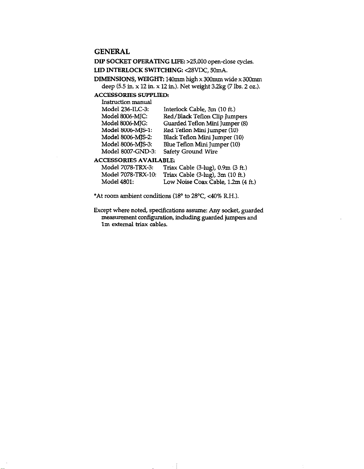
GENERAL
DIP SOCKET OPERATING LIFEz >25,000 open-close cycles.
LID INTERLOCK SWITCHING: <28VDC, 50mA.
DUIIENSIONS, WEIGHT: 14Omm high x 3OOmm wide x 3OOmm
deep (5.5 in. x 12 in. x 12 in.). Net weight 3.2kg (7 lbs. 2 oz.).
ACCESSORIES SUPPLIED:
lnstmction manual
Model 236-ILC3: Interlock Cable, 3m (10 ft.)
Model 8006-MJCz Red/Black Teflon Clip Jumpers
Model 800~MJG
Model 8006~MJS-1: Red Teflon Mini Jumper (10)
Model 8006~MJS-2:
Model 8006~MJS-3: Blue Teflon Mini Jumper (10)
Model 8007-GND-3:
ACCESSORIES AVAILABLE:
Model 7078-TRX-3: Triax Cable (3-lug), 0.9m (3 ft.)
Model 7078-TRX-10:
Model 4801: Low Noise Coax Cable, 1.2m (4 ft.)
*At room ambient conditions (18” to 28’C, ~40% R.H.).
Except where noted, specifications assume: Any socket, guarded
measurement configwation, including guarded jumpers and
lm external triax cables.
Guarded Teflon Mini Jumper (8)
Black Teflon Mini Jumper (10)
Safety Ground Wire
Triax Cable (3-lug), 3m (10 ft.)
Page 8
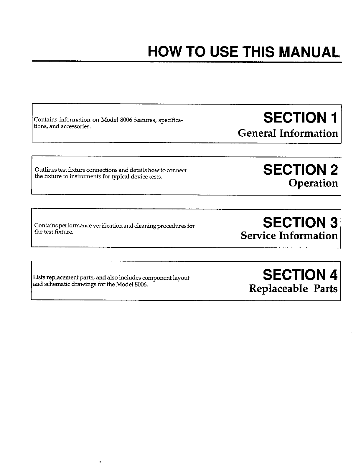
HOW TO USE THIS MANUAL
Contains information on Model 8006 features, specificatiom, and accessories.
Outlines test fixture connections and details how to connect
the fixture to instruments for typical device tests.
Contains performance verification and cleaning procedures for
the
test
fixture.
Lists replacement parts, and also includes component layout
and schematic drawings for the Model 8006.
SECTION 1
General Information
SECTION 2
Operation
SECTION 3
Service Information
SECTION 4
Replaceable Parts
Page 9
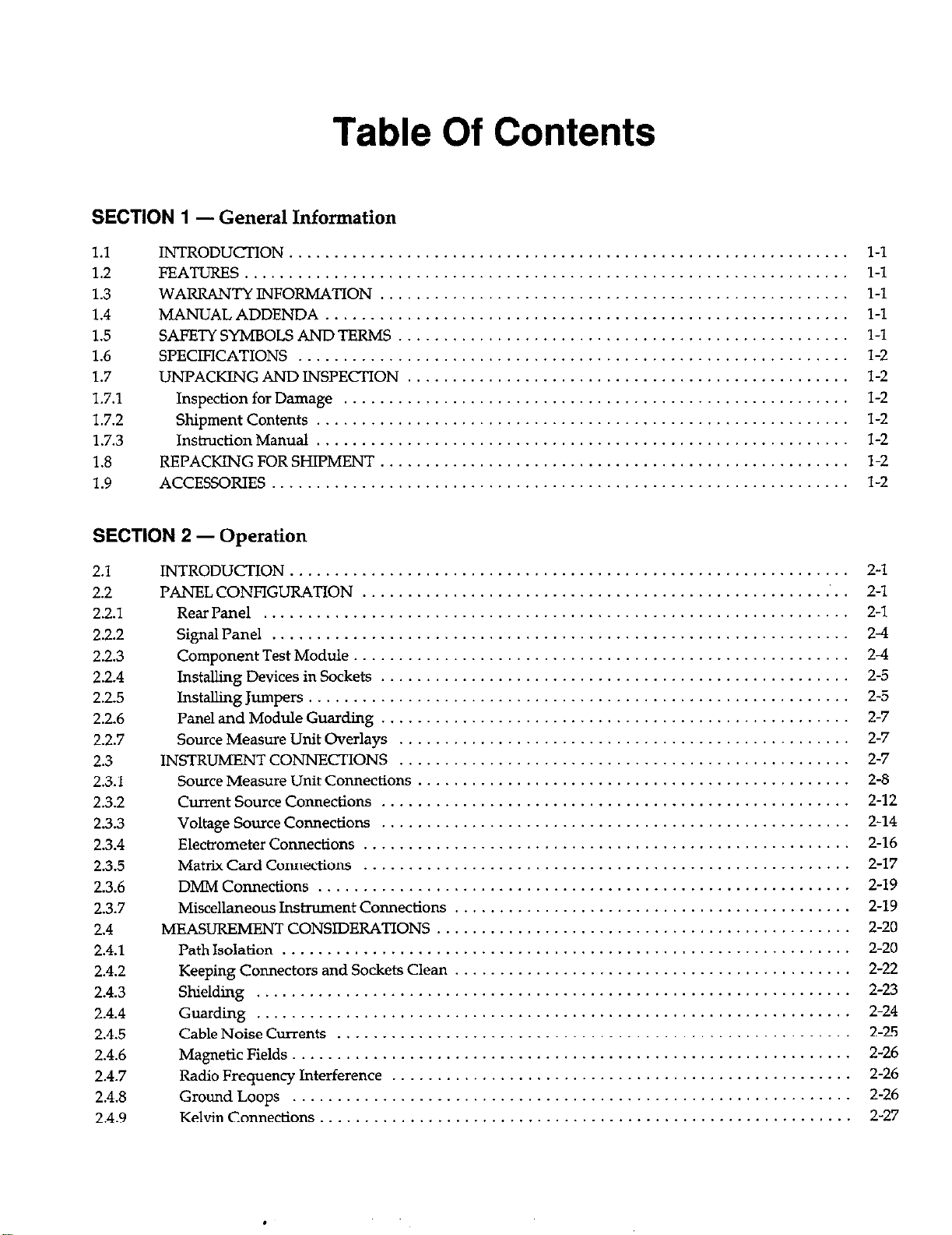
Table Of Contents
SECTION 1
1.1
- General Information
INTRODU’XION
1.2 FEATURES
1.3
WARRANTYINFORMATION
1.4 MANUAL ADDENDA
1.5 SAFETY SYMBOLS AND TERMS
1.6 SPECIFICATIONS
1.7 UNPACKING AND INSPECTION
1.7.1 Inspection for Damage
1.7.2 shipment contents
1.7.3
1.8
1.9
Instndion Manual
REPACKING FOR SHIPMENT
ACCESSORIES
SECTION 2 - Operation
2.1
2.2
2.2.1
2.2.2
2.2.3
2.2.4
2.2.5
2.2.6
2.2.7
2.3
2.3.1
2.3.2
2.3.3
2.3.4
2.3.5
2.3.6
2.3.7
2.4
2.4.1
2.4.2
2.4.3
2.4.4
2.4.5
2.4.6
2.4.7
2.4.8
2.4.9
INTRODUCTION ...........
PANELCONFIGURATION ...
RearPanel
..............
Signal Panel ....................
Component Test Module ...........
Installing Devices in Sockets ........
Installing Jumpers
................
Panel and Module Guarding ........
Source Measure Unit Overlays
INSTRUMENTCONNECTIONS
Source Measure Unit Connections
Current Source Connections ........
Voltage Source Connections ........
Electrometer
Connections ..........
Matrix Card Connections ..........
Dh4M Connections ...............
Miscellaneous Instrument Connections
MEASLJREMENT CONSIDERATIONS
Path Isolation ...................
Keeping Connectors and Sockets Clean
shiekiiig
Guarding
......................
...............
Cable Noise Currents ......
Magnetic Fields ...........
Radio Frequency Interference
Ground Loops ...........
Kelvin Connections ........
.............................
.............................
.............................
......
......
....
.............................
.............................
.............................
.....................
.....................
........................
........................
........................
....................
....................
....................
....................
....................
....................
....................
....................
....................
....................
....................
....................
....................
....................
.....................
l-l
l-l
l-l
l-l
1-l
l-2
l-2
l-2
l-2
l-2
l-2
l-2
.
2-l
2-l
2-l
24
24
2-5
2-5
2-7
2-7
2-7
2-8
2-12
2-14
2-16
2-17
2-19
.
2-19
2-20
2-20
2-z
2-23
2-24
2-25
2-26
2-26
2-26
2-27
Page 10
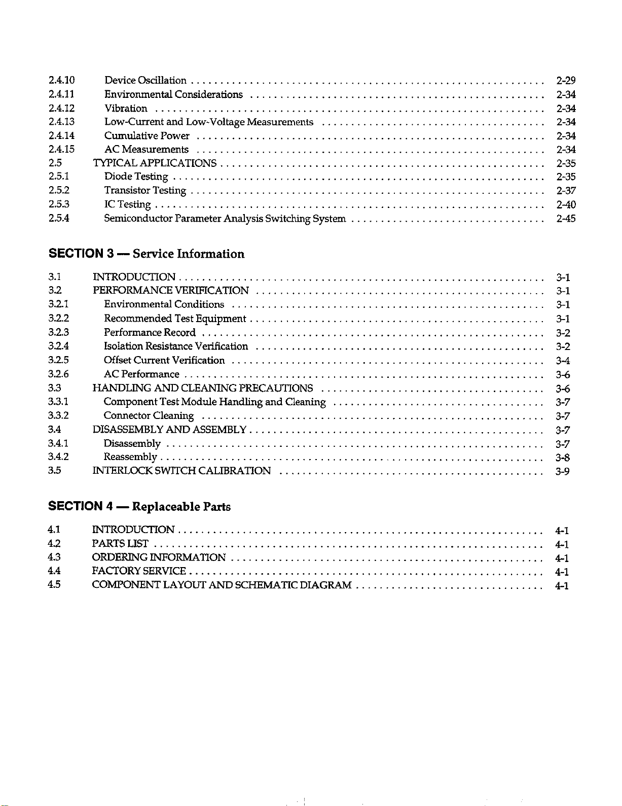
2.4.10
2.4.11
2.4.12
2.4.13
2.4.14
2.4.15
2.5
2.5.1
2.5.2
2.5.3
2.5.4
DeviceOsciIIation
Environmental Considerations
...........................
.................
Vibration .................................
Low-Current and Low-Voltage Measurements
Cumulative Power
AC Measurements
TYPICAL APPLICATIONS
DiodeTesting
Transistor Testing
..........................
..........................
......................
..............................
...........................
.....
ICTesting .................................
Semiconductor Parameter Analysis Switching System
................
................
................
................
................
................
................
2-29
2-34
2-34
2-34
2-34
2-34
2-35
2-35
2-37
240
245
SECTION
3.1
3.2
3.2.1
3.2.2
3.2.3
3.2.4
3.2.5
3.2.6
3.3
3.3.1
3.3.2
3.4
3.4.1
3.4.2
3.5
SECTION
4.1
4.2
4.3
3 - Service Information
INTRODUCTION
PERFORMANCE VERIFICATION
EnvironmentaI Conditions
Recommended Test Equipment
Performance Record
Isolation Resistance Verification
Offset Current Verification
AC Performance
HANDLING AND CLEANING PRFCAUTIONS
Component Test Module Handling and Cleaning
Connector Cleaning
DISASSEMBLY AND ASSEMBLY
Disassembly
Reassembly .............................
INTERLOCK SWITCH CALIBRATION
..........................
.............
.................
..............
......................
.............
.................
.........................
......................
..............
............................
.........
4 - Replaceable Parts
INTRODUCTION...............................
PARTSLIST . . . . . . . . . . . . . . . . . . . . .._............
ORDERTNG INFORMATION . . . . . . . . . . . . .
4.4 FACTORY SERVICE . . . . . . . . . . . . . . . .
4.5 COMPONENT LAYOUT AND SCHEMATIC DIAGRAM .
.......................
.......................
.......................
.......................
.......................
.......................
.......................
.......................
.......................
.......................
.......................
.......................
.......................
.......................
.......................
..............
..............
..............
..............
..............
. . . . . . . . . .
...........
...........
...........
3-l
3-l
3-l
3-1
3-2
3-2
34
3-6
3-6
3-7
3-7
3-7
3-7
3-a
3-9
4-l
41
41
4-l
4-l
Page 11

List Of Illustrations
SECTION 2
Figure 2-l
Figure 2-2
Figure 2-3
Figure 24
Figure 2-5
Figure 2-6
Figure 2-7
Figure 2-8
Figure 2-9
Figure 2-10
Figure 2-11
Figure 2-12
Figure 2-13
Figure 2-14
Figure 2-15
Figure 2-16
Figure 2-17
Figure 2-18
Figure 2-19
Figure 2-20
Figure 2-21
Figure 2-22
Figure 2-23
Figure 2-24
Figure 2-25
Figure 2-26
Figure 2-27
Figure 2-28
Figure 2-29
Figure 2-30
Figure 2-31
Figure 2-32
Figure 2-33
Figure 2-34
Figure 2-35
Figure 2-36
Figure 2-37
Figure 2-38
Figure 2-39
Figure 240
Figure 241
Figure 242
- Operation
Test Fixture Rear Panel
Connecting Interlock Circuit to Source Measure Units
Interlock Circuit Wiring
Front Panel Showing Signal Panel and Component Test Module
Jumper Installation Examples ..........................
Example of Module Guarding ..........................
Source Measure Unit Connections .......................
Unguarded Current Source Connections
Guarded Current Source Connections ....................
Unshielded Voltage Source Connections
Shielded Voltage Source Connections
Unguarded Electrometer Connections
Guarded Electrometer Connections ......................
Matrix Card Connections .............................
Unshielded DMM Connections .........................
Shielded DMM Connections
Path Isolation Equivalent Circuit
Path Isolation Resistance ..............................
Current Error Caused by Path Isolation Resistance
Shielding Example Using Triaxial Cables
Shielding Example Using Coaxial Cables
GuardedCircuit
....................................
Typical Guarded Signal Connections
PowerLineGroundLoops
EliminatingGroundLoops
Unshielded Kelvin Connections
Shielded Kelvin Connections
Kelvin Connections Equivalent Circuits
EliminatingOscillations
Test Configuration for Diode Tests
Jumper Installation for Diode Tests
EquiwlentCititforVFvs.IFTests
Equivalent Circuit for Leakage Test
Equivalent Circuit for Zener Diode Test
Test Configuration for Transistor Tests
Typical Jumper Installation for Transistor Tests
Test Configuration for Current Gain Test
Test Setup for Measuring Common-emitter Characteristics
Configuration for ICBO Test
Equipment Connections for Op Amp Tests
IC Power Supply Connections
Typical Jumper Installation for IC Test
...............................
........
..............................
..................
..................
....................
....................
...........................
........................
..........
..................
..................
.....................
............................
............................
........................
..........................
..................
..............................
......................
......................
....................
......................
..................
...................
.............
.................
....
...........................
................
..........................
...................
................
................
................
................
................
................
................
................
................
................
................
................
................
................
................
................
................
................
................
................
................
................
................
................
................
................
................
................
................
................
................
................
................
................
................
................
................
................
................
................
................
................
2-2
2-2
2-3
24
2-6
2-7
2-9
2-12
Z-13
2-14
2-15
2-16
2-17
2-18
2-19
2-20
2-21
2-22
2-22
2-23
2-24
2-24
2-25
2-26
2-27
2-27
2-27
2-28
2-31
2-35
2-36
2-36
2-37
2-37
2-38
2-39
240
241
241
242
242
243
Page 12
Figure 243 Circuit to Determine Input Bias Current
. . . . . . . . . . . .
Figure 244 Determining Input Offset Voltage Using DMM . , . . .
Figure 245 Determining Input Offset Voltage Using Nanovoltmeter
Figure 246
Figure 247
Semiconductor Parameter Analysis Switching System
Typical Test ConfIguration . . . . . . . _ . . . . .
....................
....................
....................
244
2-M
244
2-45
246
SECTION 3
Figure 3-l
Figure 3-2
Figure 3-3
Figure 34
Figure 3-5
Figure 3-6
Figure 3-7
Figure 3-8
- Service Information
Path Isolation Verification Triax Connections
Path Isolation Verification BNC Connections
Triex Conmdion+s for Offset Current Test .
BNC Connections for Offset Current Test
Connections for AC Response Test . . . .
Fixture Disassembly . . . . . . . . . . .
Hinge Alignment . . . . . . . . . . . .
Safety Interlock Switch Adjustment . .
. .
....................
....................
....................
....................
....................
....................
....................
....................
3-3
3-3
3-5
3-5
3-7
3-a
3-8
3-9
Page 13

List Of Tables
SECTION 3
Table 3-l
Table 3-2
- Service Information
Recommended Test Equipment .
PerfonnanceRecord . ..______.......____.__.,,._____......_.._.....,.....__ 3-2
3-1
Page 14
SECTION 1
General Information
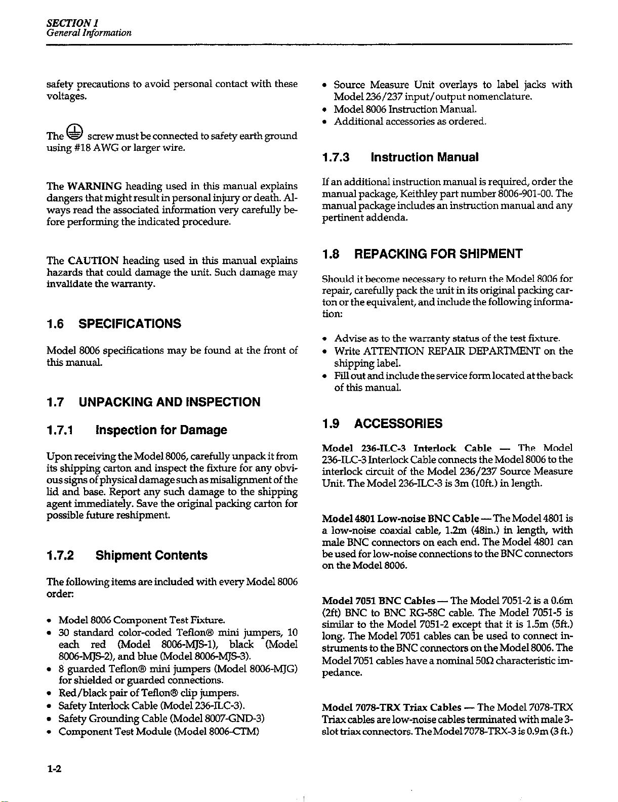
1.1 INTRODUCTION
This section contains general information about the
Model 8006 Component Test Fixture, and it is arranged in
the following manner:
1.2 Features
1.3 Warranty Information
1.4 Manual Addenda
1.5 Safety Symbols and Terms
1.6 Specifications
1.7 Unpacking and Inspection
1.8 Repacking for Shipment
1.9 Optional Accessories
1.2 FEATURES
Two axial lead sockets (2Omm and 3Omm spacing),
five TO package sockets, (two 4-pin, 8-pin, IO-pin, and
lZpin), and one 28-pin ZIF (zero insertion force) DIP
socket.
Color-coded mini jumpers supplied for easy device
connections.
All connecting points are clearly marked to minimize
the possibility of errors when making test connections.
Hinged lid with light-tight gasket and ground straps
for shielded measurements.
1.3 WARRANTY INFORMATION
Warranty information is located on the inside front cover
of this instruction manual. Should your Model 8006 require warranty service, contact the Keithley representative or authorized repair facility in your area for further
information. When returning the fixture for repair, be
sure to fill out and include the service form at the back of
this manual in order to provide the repair facility with the
necessary information.
1.4 MANUAL ADDENDA
The Model 8006 Component Test Fixture provides a convenient way to connect a variety of instrumentation to
standard packaged semiconductor devices. Although
primarily intended for use with Keithley Models 236 and
237 Source Measure Units, the Model 8006 can also be
used with a variety of other instrumentation, including
voltage and current sources, DMMs, LCR meters, oscillo-
scopes, analyzers, CV meters, and electrometers. The
Model 8006 has eight component sockets to simplify con-
nections to a variety of devices.
Key features of the Model 8006 include:
l
12 triax connectors for connecting up to six Source
Measure Units or other instrumentation requiring triaxial connections.
l
Two BNC connectors and five binding posts for additional instrument cormections.
l
Interlock connector for safe operation.
Any improvements or changes concerning the test fiuture or manual will be explained in an addendum included with the the unit. Be sure to note these changes
and incorporate them into the manual before using or
servicing the fixture.
1.5 SAFETY SYMBOLS AND TERMS
The following symbols and terms may be found on an instrument or used in this manual.
The A symbol on an instrument indicates that the
user should refer to the operating instructions located in
the instruction manual.
The
age may be present on the terminal(s). Use standard
symbol on an instrument shows that high volt-
l-1
Page 15
SECTION1
General Information
safety precautions to avoid personal contact with these
voltages.
The - screw must be connected to safety earth ground
0
using #18 AWG or larger wire.
The WARNING heading used in this manual explains
dangers that might result in personal injury or death. AIways read the associated information very carefuuy be
fore performing the indicated procedure.
The CAUTION heading used in this manual explains
hazards that could damage the unit. Such damage may
invalidate the warranty.
1.6 SPECIFICATIONS
Model 8006 specifications may be found at the front of
this manual.
1.7 UNPACKING AND INSPECTION
l
Source Measure Unit overlays to label jacks with
Model 236/237 input/output nomenclature.
l
Model 8006 Instruction Manual.
. Additional accessories as ordered.
1.7.3 Instruction Manual
If an additional instruction manual is required, order the
manual package, Keithley part number 8006-901-00. The
manual package includes an instruction manual and any
pertinent addenda.
1.8 REPACKING FOR SHIPMENT
Should it become necessary to return the Model 8006 for
repair, carefully pack the unit in its original packing carton or the equivalent, and include the following information:
. Advise as to the warranty status of the test fixture.
. Write ATTENTION REPAIR DEPARTMENT on the
shipping label.
l
Fill out and include the service form located at the back
of this manual.
1.7.1 Inspection for Damage
Upon receiving the Model 8006, carefully unpack it from
its shipping carton and inspect the fixture for any obvious signs of physical damage such as misalignment of the
lid and base. Report any such damage to the shipping
agent immediately. Save the original packing carton for
possible future reshipment.
1.7.2 Shipment Contents
The following items are included with every Model 8006
order:
Model 8006 Component Test Fixture.
30 standard color-coded Teflon@ mini jumpers, 10
each red (Model 8006-MJsl), black (Model
8006~MJSZ), and blue (Model 8006M&3).
8 guarded Teflon@ mini jumpers (Model 8CH&MJG)
for shielded or guarded connections.
Red/black pair of Teflon@ clip jumpers.
Safety Interlock Cable (Model 236-ILC-3).
Safety Grounding Cable (Model 8007-GND-3)
Component Test Module (Model 8006CTM)
1.9 ACCESSORIES
Model 236-ILC-3 Interlock Cable - The Model
236~ILC-3 Interlock Cable connects the Model 8006 to the
interlock circuit of the Model 236/237 Source Measure
Unit. The Model 236-ILC3 is 3m (loft.) in length.
Model 4801 Low-noise BNC Cable -The Model 4801 is
a low-noise coaxial cable, 1.2m (48in.1 in length, with
male BNC connectors on each end. The Model 4801 can
be used for low-noise connections to the BNC connectors
on the Model 8006.
Model 7051 BNC Cables - The Model 7051-2 is a 0.6m
(2ft) BNC to BNC RGd8C cable. The Model 7051-5 is
similar to the Model 7051-2 except that it is 1.5m (51%)
long. The Model 7051 cables can be used to connect instruments to the BNC connectors on the Model 8006. The
Model 7051 cables have a nominal 5Oa characteristic impedance.
Model 7078-TRX Triax Cables -The Model 7078-m
T&xx cables are low-noise cables terminated with male 3slot triax connectors. The Model 7078-TRX-3 is 0.9m (3 ft.)
l-2
Page 16

SECTION I
General Information
in length, and theMode 707%TRX-10 is3.Om(lO ft.) long.
The Model 707%TRX cables are recommended for making connections between the triax connectors on the
Model 8006 and external instrumentation such as the
Model 236/237 Source Measure Units.
Model 8006~CTh4 Component Test Module - The
Model 8006.CIMComponent Test Module is the module
supplied with the Model 8006 Test Fixture. The Model
8006cTM has two sets of axial lead Kelvin component
clips, five TO package sockets (two 4-pin, S-pin, IO-pin,
and 12;pin), and one 24-pin DE’ ZIF (zero insertion force
socket).
Model 8006-MJC Teflon@ Red/Black Clip Jumpers These clip jumpers can be used to make connections di-
rectly to component test leads.
Model 8006-MJG Guarded Teflon@ Mini Jumpers The Model 8006-MJG contains eight guarded mini jump-
ers like the guarded jumpers supplied with the Model
8006.
Model 8006-MJS Teflon@ Mini Jumpers -The Model
8006-MJS mini jumpers are the standard mini jumpers
supplied with the Model 8006. The jumpers are available
in three colors: black (Model 8006-MJS-I), red (Model
SC06-MJS-2), and blue (Model 8006-MJS-3). Each package
contains 10 jumpers.
Model 8007-GND-3 Safety Grounding Cable - The
Model 8007-GND-3 Safety
Groundmg
Cable is intended
for connecting fixture chassis ground to safety earth
gnxmd. One Model 8007-GND-3 is supplied with the test
fixture, and the cable is 3m (loft.) in length.
Source Measure Unit Overlays (PA-287)-The overlay
cards allow convenient identification of the rear panel
and signal panel jacks to correspond to Model 236/237
Source Measure Unit input/output nomenclature.
l-3
Page 17
SECTION 2
Operation
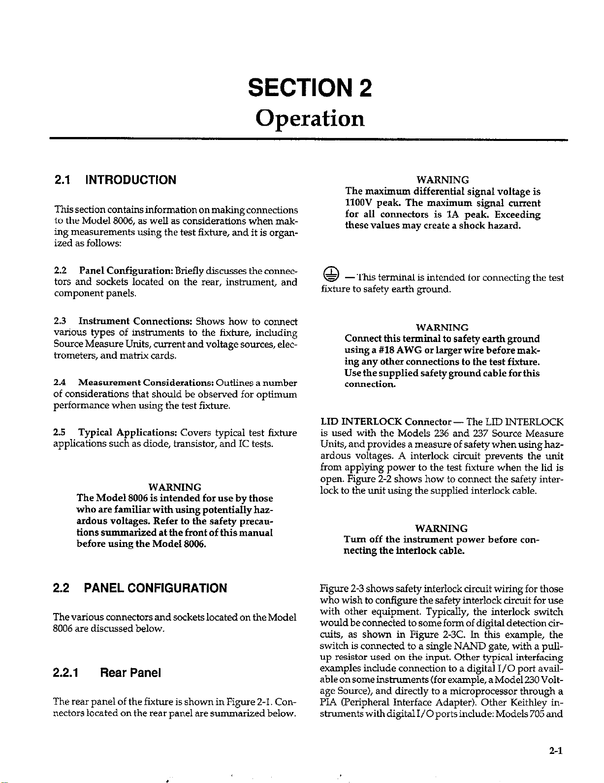
2.1 INTRODUCTION
This section contains information on making connections
to the Model 8006, as well as considerations when
ing measurements using
ized as follows:
Panel Configuration: Briefly discusses the connec-
2.2
tars and sockets located on the rear, instrument, and
component panels.
Instrument Connections: Shows how to connect
2.3
various types of instruments to the fixture, including
Source Measure Units, current and voltage sources, electrometers, and matrix cards.
Measurement Considerations: Outlines a number
2.4
of considerations that should be observed for optimum
performance when using the test fixture.
Typical Applications: Covers typical test fixture
2.5
appbcations such as diode, transistor, and IC tests.
The Model 8006 is intended for use by those
who are familiar with using potentially hazardous voltages. Refer to the safety precautions summarized at the front of this manual
before using the Model 8006.
the test fixture, and it is organ-
WARNING
mak-
WARNING
The maximum differential signal voltage is
1lOOV peak. The maximum signal current
for all connectors is 1A peak. Exceeding
these values may create a shock hazard.
@-.
fixture to safety earth ground.
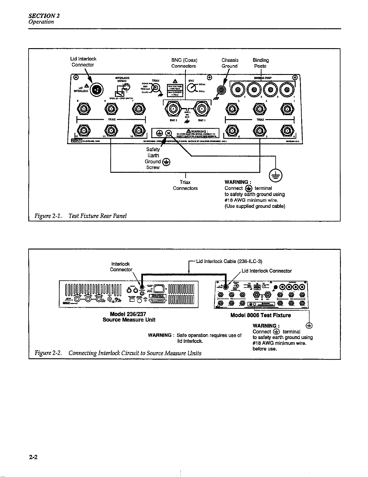
LID INTERLOCK Connector - The LID INTERLOCK
is used with the Models 236 and 237 Source Measure
Units, and provides a measure of safety when using hazardous voltages. A interlock circuit prevents the unit
from applying power to the test fixture when the lid is
open. Figure 2-2 shows how to connect the safety interlock to the unit using the supplied interlock cable.
Tlus terminal is intended for connecting the test
WARNING
Connect this terminal to safety earth ground
using a #18 AWG or largerwire before making any other connections to the test fixture.
Use the supplied safety ground cable fort&
connection.
WARNING
Turn off the instrument power before connecting the interlock cable.
2.2 PANEL CONFIGURATION
The various connectors and sockets located on the Model
8006 are discussed below.
2.2.1 Rear Panel
The rear panel of the fixture is shown in Figure 2-1. Connectors located on the rear panel are summarized below.
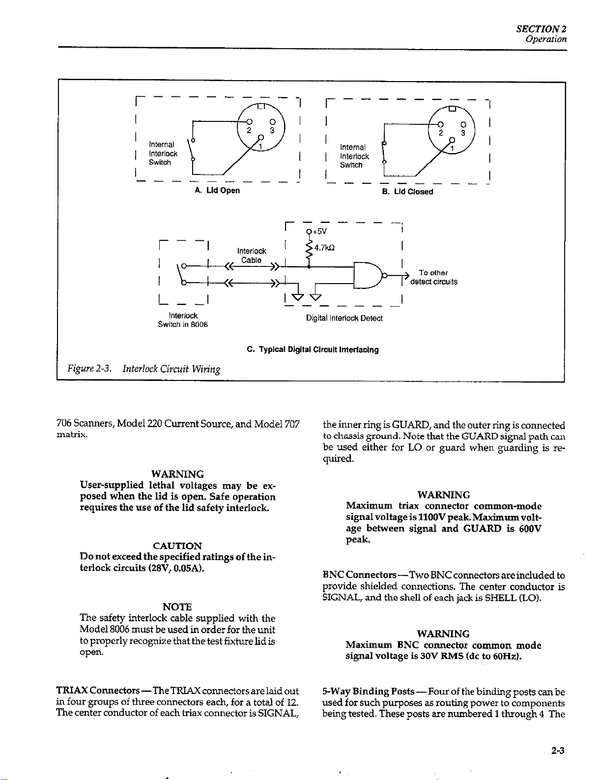
Figure 2-3 shows safety interlock circuit wiring for those
who wish to configure the safety interlock circuit for use
with other equipment. Typically, the interlock switch
would be connected to some form of digital detection circuits, as shown in Figure 2-3C. In this example, the
switch is connected to a single NAND gate, with a pullup resistor used on the input. other typical interfacing
examples include connection to a digital I/O port available on some instruments (for example, a Model 230 Voltage Source), and directly to a microprocessor through a
PL4 (Peripheral Interface Adapter). Other Keithley in-
struments
with digital I/O ports include: Models 705 and
2-l
Page 18
SECTZON 2
Operation
Lid Interlock
COllflectOr
Figure 2-1. Test Fixture Rear Panel
SNC (Coax)
COlVlFXiOlS
Chassis
Ground
Connect @ terminal
to safety earth ground using
#I 8 AWG minimum wire.
(Use supplied ground cable)
Binding
Posts
Interlock
connector
\ I
Model 2361237
Source Measure Unit
WARNING : Safe operation requires use of
lid interlock.
Lid Interlock Cable (236.ILC-3)
Figure 2-2. Connecting Interlock Circuit to Source Measure Units
, Lid Interlock Connector
WARNING :
Connect @ terminal
to safety earlh ground using
#I8 AWG minimum wire.
before use.
2-2
Page 19
SECTZON 2
Operation
Figure 2-3.
r---l
I
Internal
I ‘&$;g”
I
--------_
Interlock Circuit Wirin,q
lLlrP
A. Lid Open
I
---
I
----_
0
2 3
1
r----
I I
I I
I I
I I
-------__
r O+~V - - - -/
l**
-----__
Digital Interlock Detect
C. Typical Digital Circuit tnterfacing
Internal
Interlock
Switch
i
q
. Lid Closed
I
0
2 3
1
706 Scanners, Model 220 Current Source, and Model 707
matrix.
WARNING
User-supplied lethal voltages may be exposed when the lid is open. Safe operation
requires the use of the lid safety interlock.
CAUTION
Do not exceed the specified ratings of the interlock circuits (28V, 0.05A).
NOTE
The safety interlock cable supplied with the
Model 8006 must be used in order for the unit
to properly recognize that the test fixture lid is
open.
TRIAX Connectors-TheTRL4X connectors are laid out
in four groups of three connectors each, for a total of 12.
The center conductor of each t&.x connector is SIGNAL,
the inner ring is GUARD, and the outer ring is connected
to chassis ground. Note that the GUARD signal path can
be used either for LO or guard when guarding is required.
WARNING
Maximum trim connector common-mode
signal voltage is 1lOOV peak. Maximum voltage between signal and GUARD is 600V
pd.
BNCConnectors-TwoBNCconnectorsareincludedto
provide shielded connections. The center conductor is
SIGNAL, and the shell of each jack is SHELL (LO).
WARNING
Maximum BNC connector common mode
signal voltage is 30V RMS (dc to 60Hz).
5-Way Binding Posts-Four of the binding posts can be
used for such purposes as routing power to components
being tested. These posts are numbered 1 through 4 The
2-3
Page 20

SECTION 2
Operation
fifth binding post is chassis ground, and it is intended for
measurement grounding connections only.
WARNING
With hazardous voltages (>3OV RhCS, observe the following safety precautions when
using banana plugs.
1. Turn off all sources and discharge all capacitors before connecting them to the
banana plugs.
2. Dress all wires to ensure that no conductive surfaces are exposed after connecting
them to the binding posts.
3. Always use the lid interlock with any
scmrces connected to the banana plugs
(see the lid interlock discussion above).
2.2.2 Signal Panel
Figure 2-4 shows the signal panel of the test fixture. The
signal panel has a number of test jacks that provide con-
necting points for the input/output pathways via the
rear panel connectors. Each test jack on the panel is
clearly marked with the corresponding rear panel connector terminal. For example, the four sets of triax terminals are individually marked as SIGNAL and GUARD to
correspond to the SIGNAL and GUARD terminals of
each rear panel TRIAX connector. The TRIAX connectors
are numbered 1 through 12 in the same manner as the
rear panel connector numbering.
The signal panel also has a test jack (PANEL SHIELD)
that is connected to the shield located immediately under
the signal panel. This jack can be connected to circuit LO
for additional shielding, or it can be guarded by connecting it an appropriate guard potential from one of the signal panel jacks.
2.2.3 Component Test Module
Figure 24 shows the component test module, which contains sockets for a variety of device packages. These sockets include:
Signal
Panel
Component Test
Module Shield
Connection
t-
Module Fasteners
‘igure 24. Front Panel Showing Signal Panel and Component T&Module
I-
+
Triax
COnIlSCtiOllS
ZIF Socket
Handle
2-4
!
Page 21

SECTION 2
Operdon
Two axial Kelvin clip pairs (2Omm and 3Omm spacing):
Used for two-terminal axial-lead devices such as diodes,
capacitors, and resistors. Each clip has a SENSE and a
SOURCE connection which provide Kelvin
to the device.
Two 4-pin TO package sockets (small pin and large pin):
Intended primarily for use with transistors.
Three multi-pin TO package sockets (S-pin, IO-pin, and
l&pin TO-5): Designed for use with multi-pin transistor
and IC packages.
28-pin dual in-line package ZIF socket: Accepts DIP
packages up to 28 pins with 0.3 to 0.6in. lead spacing. The
associated handle should be raised to open the socket,
lowered to close the socket.
Each socket terminal has an associated test jack intended
to connect that terminal to the desired input/output
pathway using the supplied mini jumpers.
connections
2.2.4
Device Handling
When handling very high impedance devices (such as
high-megohm resistors) be careful not to contaminate the
body of the device, which would lower its impedance.
Also take care when handling static-sensitive devices
such as MOSFETs so as not to damage them with static
discharge. Handle such devices only at a grounded work
station, and also ground yourself with a suitable wrist
strap. Keep static-sensitive devices in their protective
containers until ready for testing.
Axial Kelvin Clips
To install an axial component such as a resistor or diode
in one of the two sets of axial Kelvin clips, hold the device
by the test lead ends, then carefully push the device leads
down into the clips until the device is properly seated.
Installing Devices in Sockets
NOTE
With some devices, you may encounter device oscillation which could affect measurements. Refer to paragraph 2.4.10 for details on
verifying and preventing oscillation.
One of the test jacks (MODULE SHIELD) is connected to
a box shield immediately under the component test module. This jack allows the shield to be connected to circuit
LO for additional shielding, or to a guard potential if de-
sired.
Module Removal and Installation
The Model 8006~CTM Component Test Module is de-
signed for easy removal and installation. Additional
modules can be purchased, allowing several device and
circuit configurations to be easily interchanged for rapid
testing.
To remove the component test module, first disconnect
all jumpers to the signal panel, then pulJ up on the four
fasteners that secure the module to the base (see
Figure Z-4 for locations). After the fasteners are released,
pull up on the module to remove it from the base.
To install the module, install it in the base with the fasten-
ers aligned in the corresponding holes, then push down
on the four fasteners to secure the module to the base.
TO Package Sockets
For TO package installation, carefully spread the leads
apart so that they will line up with the holes in the socket,
then slide the device leads down into the holes, taking
care not to bend any of the leads. When installing these
devices, be sure to line up the tab on the package body
with the indicated tab position on the panel. Doing so
will ensure that the numbers on the panel will corre
spend to the actual device terminal numbering.
DIP Socket
Toinstall a deviceontheDIPsocket, firstraisetheleverat
the side of the socket to open the socket, then carefully install the device on the socket. Once the device is properly
seated, lower the lever to lock the device into place.
To remove a device from the DIP socket, first raise the
lever, then pull the device free of the socket.
2.2.5 Installing Jumpers
In order to complete device connections, it will be necessary for you to install the mini jumpers between the ap-
2-5
Page 22

SECTION 2
Operation
propriate socket jacks and the desired input/output
pathway jacks located on the signal panel.
Standard Mini Jumpers
For many cormections, the standard color-coded jumpers
supplied with the Model 8006 can be used. These jumpers
can be stacked to allow two or more connections to a single jack. Figure 2-5 shows an example of jumpers installed between the binding uost jacks and one mix of ax-
1
ial component sockets usi@ 4&e connections.
Guarded Jumpers
For critical measurements requiring low offset current,
low noise, or high path isolation, the guarded jumpers
should be used with the jumper shield connected to the
Standard
Jumper
appropriate GUARD or SHELL jack on the signal panel.
Doing so will shield or guard the sensitive pathway right
down to the device socket.
Figure 2-5 also shows an example of connections using a
guarded jumper. Note that the jumper shield is connected to the GUARD terminal of one of the triax connecting jacks, while the center conductor at the same end
is connected to SIGNAL.
WARNING
Make certain hazardous voltages are notpresent on any of the front panel terminals before installing jumpers. To avoid a possible
shock hazard, always use the lid safety interlock, and discharge all capacitors before installing or removing jumpers.
Guarded Jumper
(Connect shield to ward)
Page 23
SECTION 2
Owation
Jumper Cleaning
In critical applications, or in high-humidity environ-
ments, it
Freon@ or methanol before using them. Allow the jump-
ers to dry thoroughly (several hours in a low-humidity
environment) before use, and handle
clean gloves after cleaning to avoid new contamination.
All jumpers should be periodically cleaned with Freon@
or methanol to remove dirt or other contamination that
could degrade overall performance. Again, cleaned
jumpers should be allowed to dry for several hours in a
low-humidity ambient-temperature environment, or for
30 minutes to one hour in a 50°C low-humidity environ-
ment before use.
2.2.6
Each triax pathway can be individually guarded by applying the guard signal to the inner shield of the cable.
When using the Model 236 or 237 Source Measure Unit,
guard is automatically applied through the inner shield
of the OUTPUT HI and SENSE HI connectine cables and
appears at the
may
be necessary to clean the coax jumpers with
them only
Panel and Module Guarding
GUARD jacks
for the assoduted signal
with
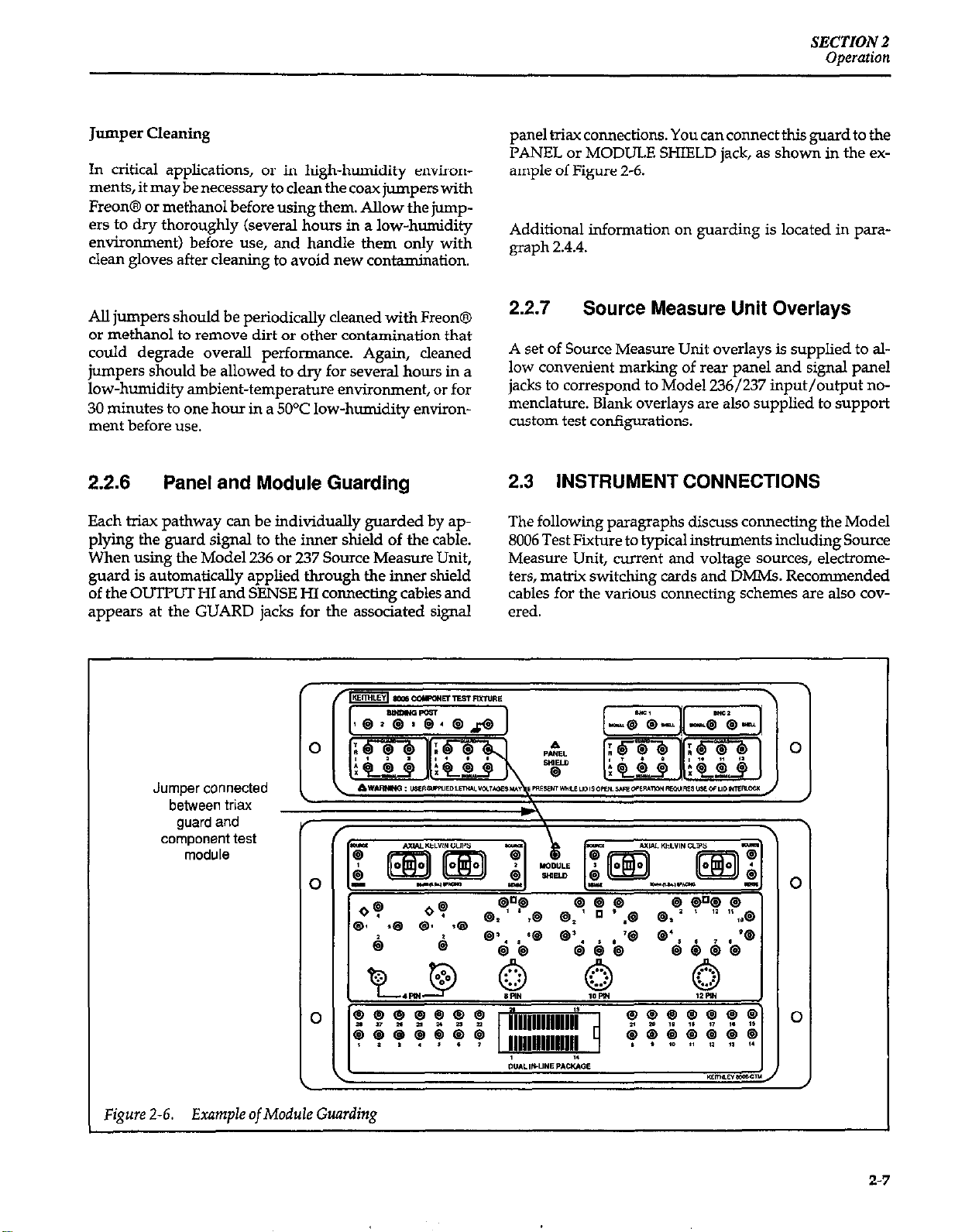
panel triax connections. You can connect this guard to the
PANEL or MODULE SHIELD jack, as shown in the example of Figure 2-6.
Additional information on guarding is located in paragraph 2.4.4.
2.2.7
A set of Source Measure Unit overlays is supplied to allow convenient marking of rear panel and signal panel
jacks to correspond to Model 236/237 input/output nomenclature. Blank overlays are also supplied to suppoti
custom test configurations.
Source Measure Unit Overlays
2.3 INSTRUMENT CONNECTIONS
The following paragraphs discuss connecting the Model
8006 Test Fixture to typical instruments including Source
Measure Unit, current and voltage sources, electrometers, matrix switching cards and DMMs. Recommended
cables for the various connectine schemes are also covered.
”
Jumper connected
between triax a
guard and
component test
module
Figure 2-6. Example of Module Guarding
2-7
Page 24

SECTION 2
operation
WARNING
Do not exceed the maximum test fiie signal level, as defined in the specifications and
stated on the rear panel. Always bun off all
power and discharge all capacitors before
connecting or disconnecting cables. Lethal
voltages may be exposed when the lid is
open. Safe operation requires the use of the
lid safety interlock (see paragraph 2.2.1).
2.3.1 Source Measure Unit Connections
Typical connections between the Model 8006 and the
Model 236/237 Source Measure Units are shown in
Figure 2-7. Note that remote sensing, and two connecting
methods for local sensing are shown.
NOTE
With some devices, you may encounter device oscihtion that will affect your measurements. Refer to paragraph2.4.10 for details on
verifying and preventing oscillation.
both OUTPUT LO and SENSE LO via the inner shield
and center conductor respectively.
Be careful not to confuse the terminal conventions on the
Source Measure Unit and the test fixture. HI appears on
the SIGNAL jacks,and guard OUTPUT HI and SENSE HI
actnally appears on the GUARD jacks on the signal panel
of the test fixture. As with all connections, you must complete the connections to the DUT in the appropriate device socket with the mini jumpers. Use standard mini
jumpers for unshielded and unguarded pathways, and
use guarded jumpers for guarded or shielded pathways.
Local Sensing Connections (Banana Plug for LO)
Connections for local sensing require only one fxiax ca-
ble, and a single banana plug patch cord (Figure2-7C and
2-7D). Note that local sensing is recommended only for
lower current situations where voltage drops XTOSS the
test cables and connectors is not a consideration. Also,
this configuration is recommended for less-critical applications where noise is not a problem.
Remote Sensing Connections
Remote sensing connections are shown in Figure 2-7A
and 2-78. Model 7078-TRX t&x cables are recommended
for all three connections. For the OUTPUT HI and SENSE
HI cables (A and B), the center conductor is HI, the inner
shield is GUARD, and the outer shield is chassis ground.
Note that the remaining cable (connected to C) carries
Local Sensing Connections (T&IX Cable for LO)
Where noise pickup is a consideration, the local sensing
connections shown in Figure 2-m and 2-7F are recommended. Here, two Model 7078~TRX tiax cables are used
to connect the Source Measure Unit to the test fixture.
When installing jumpers, keep in mind that OUTPUT LO
appears on GUARD on the signal panel with this connection scheme.
2-8
Page 25

Model 2361237
Source Measure Unit
A. Connections (Remote sensing)
SECTION 2
Operation
Firm 2-7. Source h4easure
336/237
Source Measure Unit
Unit
Connections
6. Equivalent Circuit (Remote Sensing)
2-9
Page 26

SEC’TZON 2
Operation
Model 236/237
Source Measure Unit
C. Connections (Local sensing, banana plug for LO)
kwce
Measure Unit Connections (Cont.)
I
236i237
8ource Measure Unlt
D. Equivalent Circuit (Local sensing, banana plug for LO)
I
2-10
Page 27

Model 238/237
Source Measure Unit
E. Connections (Local sensing. triax for LO)
SECTION 2
Operation
F. Equivalent Circuit (Local sensing. Via for LO)
~urce Measure Unit Connections (Cont.)
2-11
Page 28

SECTION 2
Operation
2.3.2 Current Source Connections
Unguarded Connections
Figure 2-8 shows unguarded connections between the
test fixture and a typical current source, a Keithley Model
220. Again, a Model 7078-m triax cable is recommended for connections. A Model 617’2 Z-slot to Slug
adapter will be necessary at the current source output
jack. Note that the center conductor is HI, the inner shield
is LO, and the outer shield is chassis ground.
Guarded Connections
Guarded connections can also be made using a Model
6167 Guarded Adapter along with the current source, as
shown in Figure 2-9. In this instance, the triax cable carries HI on the center conductor and GUARD on the inner
shield. LO is routed through a separate wire connected
between current source OUTlWT COMMON and a test
fixture binding post. In some cases, it may be necessary to
shieldLOustigtriaxialorcoaxialcabletominimizenoise
pickup.
The Model 6167 Guarded Adapter normally connects
output LO to the outer shell of the output triax connector,
and it must be modified. to avoid connecting current
source LO to chassis ground at the test fixture end. To
modify the fixture, disconnect the internal wire going to
the ou$ut triax connector outer shell.
- -
Figure 2-8.
220 Current Source
A. Connections
Unguarded Current Source Connections
I
Model80~ ~~ I06 Test Fixture
WARNING: 0
connecl @ terminal
to safety emh ground using
tt8 AWG minimum wire
before use.
I
2-12
Page 29

A. Connections
SECTION 2
Operation
Figure 2-9.
220 current Commm
SWrC.3
B. Equivalent Circuit
Guarded Current Source Connections
POsf
2-13
Page 30

SECTION 2
Operation
2.3.3
Voltage Source Connections
Unshielded Connections
Shielded Connections
For low signal levels or noisy test environments, shielded
connections should be used to minimize noise
(Figure 2-11). A male BNC to dual banana plug coaxial
Unshielded voltage source connections are shown in
Figure 2-10. Here, OUTPUT HI and LO are connected to
test fixture binding posts using banana plug patch cords
(Pomona B-36-O and B-36-2).
cable (Pomona 2BC-BNC36) should be used for connec-
tions. At the voltage source, the cable shield should be
connected to OUTPU’I LO, and the center conductor
should be connected to OUTl’UT HI.
WARNING
For remote sensing, add the indicated cords and jumpers Do not float the Model 230 more than 30V
(shown with dashed lines).
RMS above earth ground.
230 Voltage Source
r-IT<
sense
OUtpA
G----D3
230 Voltage Source
6. Equivalent Circuit
Figure 2-10. Unshielded Voltage Source Connections
signal Pam
Binding
post * 2
6066 Test Fixture
Model 8006 Test Fixture
Component
Test Module
h
I
=
2-14
Page 31

A. Connections
SECTION 2
Operation
Figure 2-11.
6. Equivalent Circuit
Shielded Voltage Source Connections
2-15
Page 32

SECTION 2
Operation
2.3.4
Unguarded Connections
Typical unguarded electrometer connections are shown
in Figure 2-12. Again, a single Model 7078-TRX hiax cable can be used to make the connections. The center conductor is HI, the inner shield is LO, and the outer shield is
chassis ground. A Model 6172 2-slot to 3-lug adapter will
be necessary on the electrometer INPUT jack to adapt the
cable to the electrometer INPUT connector. Note that
V-R GUARD should be off, and the ground link between
chassis ground and COM should be removed. Typical
voltage source conneciions are also shown in Figure 2-12.
Electrometer Connections
Guarded Connections
Figure 2-13 shows guarded electrometer connections.
Again, a t&x cable/adapter combination is used between the electrometer INPUT jack and the desired hiax
connector on the test fixture. In this case, the center conductor is HI, the inner shield is GUARD, and the outer
shield is chassis ground. LO is separately routed by connecting electrometer COM to a test fixture binding post
using an ordinary patch cord. If measurement noise is a
problem, route LO through a shielded path (either coax
or hiax) using suitable cables.
For guarded measurements, the V-Q GUARD switch on
the electrometer should be in the ON position. Also, the
ground link between chassis ground and COM should
normalIy be removed. In some cases, however, low-noise
617 Electrometer
817 Electrometer
6. Equivalent Circuit
Figure Z-12. Unguarded EJectrmneter Connections
Model 6006 Test Fixture
1
8008 Test Fixture
I
“SWl”Stdbd
J”“pNS
2-16
Page 33

SECTION2
c$=$---‘~;--?~;~~
Operation
performance may be obtained with the ground link installed.
2.3.5
Typical connections to a Model 7072 Semiconductor Ma-
ti Card are shown in Figure 2-14. Direct connections
without adapters using Model 707%TRX triax cables are
used. Each cable carries SIGNAL (can be HI or LO) on the
Matrix Card Connections
center conductor, GUARD on the inner shield, and chassis ground on the outer shield.
Connections to othertypes of matrix cards can bemade in
a similar manner by using the appropriate cables. For example, connections to a Model 7073 Coaxial Matrix Card
would be similar except that coaxial cable to the BNC
connectors would be made instead of the tiax combination shown in Figure 2-14.
I
617 Electrometer
B. Equivalent Circuit
Figure 2-13. Guarded Electrometer Connections
8006
Test Fixture
2-17
Page 34

SECTION2
Operation
Figure 2-14. Matrix Card Connections
A. Connections
6. Equivalent Circuit (Two pathways shown)
before “se.
rni”irn”rn wire
2-18
Page 35

SECTION 2
Operation
2.3.6
Unshielded Connections
Figure 2-15 shows typical unshielded DMM connections.
VOLT/OHMS HI and LO are connected to the binding
posts using ordinary banana plug patch cords (Pomona
B-36-O and B-36-2). For 4-wire measurements, simply
connect two additional patch cords between OHMS
SENSE HI and LO and the remaining two binding posts,
as well as additional jumpers (shown as dashed lines).
Shielded Connections
If measurement noise is a consideration, the shielded
connections shown in Figure 2-l 6 should be used. A male
BNC to dual banana plug cable (Pomona 2BC-BNC-36) is
recommended for shielded connections. Connect
VOLTS/OHMS HI to the center conductor, and connect
VOLTS/OHMS LO to the cable shield. If shielded 4-wire
connections are required, connect a second shielded ca-
DMM Connections
ble between OHMS SENSE HI and LO and the remaining
BNC connector on the test fixture.
2.3.7
Miscellaneous Instrument Connections
Other instruments such as oscilloscopes, CV meters, LCR
meters, and network analyzers can also be connected to
the test fixture using appropriate cables. The cables used
will, of course, depend on the type of connector(s) on the
test instrument. The following general recommendations
apply when connecting these types of instruments to the
Model 8006.
50.Q BNC Connections
For instruments requiring 500 BNC connections, the
Model 7051 BNC cables are recommended. Connect the
cables to the BNC 1 or BNC 2 jacks on the test fixture. If
more
than two BNC connections are required, these BNC
cables can be connected to the test fixture TRIAX jacks us-
Figure 2-15. Unshielded DMh4 Connections
B. Equivalent Circuit
2-19
Page 36

SECTION 2
Operation
Model 196 DMM
A. Connections
B. Equivalent Circuit
Figure 2-16. Shielded Dh4h4 Connections
ing Model 7078-TRSBNX triax-to-BNC adapters. Note,
however, that the 5OQ impedance may not be maintained
through the adapters and triax jacks.
Low-Noise BNC Connections
6006 Test Fixture J.
As an alternative to the above arrangement for 2-lug
jacks, you can use Model 7024 triax cables, which are terminated with Z-slot male connectors on each end. Model
6171 3-slat to Z-lug triax adapters will be necessary to
connect these cables to the TRL4X connectors on the test
fixtwe jacks.
For low-noise BNC connections, Model 4801 low noise
coaxial cables are recommended. Connect these cables to
BNC 1 or BNC 2 on the test fixture. Again, these cables
can also be connected to the TRL4X connectors using
Model 7078-TRX-BNC adapters, if required.
Triaxial Cable Connections
Instruments equipped with triax connectors can be con-
nected to the desired test fixture TRL4X jack(s) using
Model 7078-W triax cables. Since these cables are
equipped with 3-slot male triax connectors, a Model 6172
2-&t to 3-lug triax adapter will be necessary to connect
the cables to instrument equipped with Z-lug female triax
connectors.
Z-20
2.4 MEASUREMENT CONSIDERATIONS
Many
measurements
affected by noise and leakage paths. The following para-
graphs discuss possible problems that might affect these
measurements and ways to minimize their effects.
2.4.1
Path isolation is simply the equivalent impedance be-
tween any two test paths in a measurement system. Ide-
ally, the path isolation should be infinite, but the actual
resistance and distributed capacitance of cables, connec-
Path Isolation
made with the Model 8006 can be
Page 37

SECTION 2
Operation
tars, and sockets results in less than infinite path isolation
values for these devices.
Equivalent Circuit
The equivalent path isolation circuit is shown in
Figure Z-17. The path isolation resistance, RF, and the
path isolation capacitance, CP, are assumed to be lmpsum values, and they represent the isolation from one
SIGNAL pathway to another including one-meter triax
cables and guarded jumpers to the socket connecting
jack. In this instance, tiax pathways are shown, but path
isolation to BNC and binding-post pathways is similar.
Isolation Resistance
Path isolation resistance forms a signal path that is in parallel with the equivalent resistance of the DUT, as shown
in Figure 2-18. For low-to-medium device resistance mlues, path isolation resistance is seldom a consideration;
however, it can seriously degrade measurement accuracy when testing high-impedance devices. The Current
flowing through such a device, for example, can be substantially attenuated by the current divider action of the
device source resistance and path isolation resistance, as
shown in Figure 2-19. Such leakage paths (RPATH) bleed
some of the current away from the device under test
(Row), reducing measurement accuracy.
Test Fixhue Isolation Resistance
The path isolation of the test fixture itself depends on the
connectors and sockets being used. For the triax and BNC
connectors, thelimitigfactor is thesocket,with the axial
and TO sockets having substantially higher guaranteed
path isolation values than the DIP socket. The typical isolation for the Dll? socket is much better, however; see the
specifications for complete details.
The path isolation value for the binding posts is much
lower than for the BNC and triax connectors. For that reason, the binding posts should only be used for non-critical signal paths such as power supply routing.
Path Isolation Capacitance
Any distributed capacitance between measurement
pathways affects dc measurement settling time as well as
ac measurement accuracy. Thus, it is important that such
capacitance be kept as low as possible. Although the distributed capacitance of the test fixture is generally fixed
by design, there is one area where you do have control
over the capacitance in your test system: the connecting
>
I
t-
Triax
Cables
1
Figure 2-17. Path Isolation Equivalent Circuit
1
I
Cp = Path Isolation
Capacitance
8006 Test Fixture
2-21
Page 38

SECTION 2
Operation
r-----, r-----~
I
I
I
I I I
I
I __
I -EDLIT I I
I I I
I
L-----J L-----J
R
DUT
R PATH
! I I I
I I I I
I I
DUT
I I RPATH
I I
I I
Test Fixture
R DUT
E DUT
= Source resistance of DUT
= Source voltage of DUT
= Path isolation resistance
= Input resistance of measuring instrument
RIN
I I
I I
I
I I
I I
I I
I I
r-----
I RIN
L------l
Measuring Instrument
1
I
I
I
I
I
I
Figure 2-18. Path Isolation Resistance
I DUT
R
DUT
Figure 2-19. Current Error Caused bypath Isolation Re-
sistance
cables. Use only low-capacitance cabling, and keep all cables as short as possible. Also, guarded jumpers minimize path capacitance to the test sockets.
Test Fixhw Isolation Capacitance
The test fixture isolation capacitance depends on the
socket in question. In general, the isolation capacitance is
much lower for the axial component socket than for the
TO or
DIP
package sockets.
Keep in mind that the capacitance is highest between ad-
jacent terminals
of a given socket. For that reason, it may
be advantageous to measure low capacitance values be-
tween non-adjacent terminals of a socket whenever possible.
Minimizing Path Isolation Effects
The effects of path resistance and capacitance can be
minimized by using guarded jumpers whenever possi-
ble. Paragraph 2.4.4 discusses guarding in more detail.
2.4.2 Keeping Connectors and Sockets
Clean
As is the case with any high-resistance device, the integrity of connectors and sockets can be compromised if they
are not handled properly. If the insulation becomes contaminated, the path isolation resistance will be substantially reduced, affec!ing high-impedance measurements.
Oils and salts from the skin will contaminate insulators,
reducing their resistance. Also, contaminants present in
2-22
Page 39

SECTION 2
Omration
the air can be deposited on the insulator surfaces. To
avoid these problems, never touch the connector or sock-
et insulating material. In addition, the test fixture should
be used only in clean environments to avoid contamination.
If the connector or socket insulators should become contaminated, either by inadvertent touching or from airborne deposits, they can be cleaned with a cotton swab
dipped in clean methanol. After thorough cleaning. they
should be allowed to dry for one-half to one hour in a
low-humidity environment before we, or they can be
dried more quickly using dry nitrogen gas. Do not use air
from an ordinary air compressor because oil present in
the air may result in contamination. Also, do not use air
from a tank because it can cause moisture to condense on
the socket.
2.4.3
Shielding
Proper shielding of all signal paths and devices under
test is important to minimize noise pxkup in virhlauy
any semiconductor test system. Otherwise, interference
from noise sources such as line frequency and RF fields
can st?riously corrupt a measurement.
Coaxial Cable Shielding
Coaxial cables can also be used to provide effective
shielding. Connect each coaxial cable to one of the BNC
connectors on the test fixture. The center conductor
should be connected to HI of the test instrument, and the
cable shield should be connected to LO, as in the example
of Figure Z-21. Coaxial cables can also be connected to
one of the triax connectors by using a Keithley Model
707%TRX-BNC triax to BNC adapter.
WARNING
Do not apply driven guard to coaxial cables
because hazardous voltages may be placed
on the outer cable shields, creating a possible shock hazard. Maximum common-mode
voltage for the BNC jacks (or any BNC cable)
is 30V RMS (dc to 60Hz).
Panel and Module Shielding
In many cases, it may be desirable to connect the signal
panel or component module shields to circuit LO or chassis ground. To do so, simply connect a mini jumper between each shield jack to the appropriate circuit terminal
(LO or chassis ground). As with any shielding situation,
experimentation may be necessary to determine the con-
figuration that results in the lowest noise.
Triaxial Cable Shielding
For unguarded measurements, the inner shield of thetri-
axial cable that surrounds the signal path should be connected to signal LO (or to chassis ground for instruments
without isolated LO terminals). An example of how to
maintain a shielded pathway from an instrument to the
test fixture is shown in Figure Z-20.
, , -lr
smdng 0,
mas”ring
l”Rmme”t
1. _,”
Ftgure 2 20
Shzldtng Example Using Triaxiul C.&es
Jumper Shielding
Guarded jumpers should be used in cases where the
shield must be carried through as close to the device
socket as possible. Simply connect the jumper shield to a
shield connection on the signal panel. Typically circuit
GUARD will be used as the shield connecting point, although better noise performance may obtained by con-
I
6006 Test Fixture
!
I
Z-23
Page 40

SECTION 2
Operation
I
Instrument
I
“’ \,,.a,, u
grounded on
some instruments
Figure Z-21. Shielding Example Using Coaxial Cables
netting shields to chassis ground in some cases. The same
general consideration applies to shield connection points
throughout a test system. Usually, experimentation is the
best way to determine the best shielding configuration.
In order to avoid ground loops, connect the shield to only
to one point in the drcuit.
2.4.4 Guarding
Signal Panel Te*t Module
8006 Test Fixture
Component
1
I
Guarding is especially important in high-impedance circuits where leakage resistance and capacitance could
have degrading effects on the measurement. Guarding
consists of using a shield surrounding a conductor that is
carrying the high-impedance signal. This shield is driven
by a low-impedance amplifier to maintain the shield at
signal potential. For kiaxial cables, the inner shield is
used as guard.
Guarding Principles
Guarding
minimizes leakage resistance effects by driving the inner cable shield with a unity-gain amplifier, as
shown in Figure 2-22. Since the amplifier has a high input
impedance, it
minimizes loading on the high-impedance
signal lead. Also, the low output impedance ensures that
the shield remains at signal potential, so that virtually no
leakage current flows through the leakage resistance, Rr.
Leakage between inner and outer shields may be considerable, but that leakage is of little consequence because
that cumnt is supplied by the buffer amplifier rather
than the signal itself.
In a similar manner, guarding also reduces the effective
cable capacitance, resulting in much faster measurements on high-impedance circuits. Because any distributed capacitance is charged through the low impedance
of the buffer amplifier rather than by the high-impedance
E,
= DUT source voltage
Rs = DUT source resistance
RL = Leakage resistance
‘igure 2-22. Guarded Circuit
source, settling times are shortened considerably by
guarding.
Using Guarding
In order to use individual pathway guarding effectively
with the Model 8006, the inner shield of the connecting
triaxial cable carrying the HI signal path should be connected to the guard output of the sourcing or measuring
instrument. That guard output must be at the same dc potential as the signal being guarded. Many instruments
such as the Model 236/237 Source Measure Units automatically drive. the inner shield of the HI signal pathways
2-24
Page 41

SECTION 2
opmtion
at guard potential (in the case of the Model 2% and 237,
both OLITPUT Hl and SENSE HI are separately
guarded).
Any LO signal pathways
need not be guarded. For the LO signal path, simply connect the inner shield to LO at the measuring or sourcing
instrument.
Typical Guarded Connections
Figure 2-23 shows typical guarded connections, with the
guard path carried through the inner shield of the con-
necting cable. Note that guard appears on the GUARD
jack of the signal panel on the test fixture. Also note that
LO is routed through a binding post in this example; in
some cases, it may be necessary to connect LO using
shielded wire to avoid detrimental effects on the measurement.
Panel and Module Guarding
running through triaxial cables
nal panel and the signal panel or component test module
shield jack, as required.
Jumper Guarding
With sensitive measurements, guarding can be carried
through to the device socket by using the guarded jurnpers in place of the standard jumpers. To connect these
jumpers for guarding, simply connect the jumper shield
to the guard potential on the signal panel. For example, if
you are using a Model 236/237, guard appears on the
GUARD jack for the associated signal panel connections.
WARNING
Hazardous voltage may be present on
GUARD.
2.4.5
Noise currents canbe generated by bending or flexing the
triaxial or coaxial connecting cables. These currents,
which are known as triboelectric currents, are generated
by charges created between a conductor and insulator
caused by friction between conductors and insulators.
Cable Noise Currents
For very critical measurements, it may be desirable to
connect the instrument panel or component test module
shields to guard potential. To do so, simply connect a
mini jumper between the desired GUARD jack on the sig-
Instrument
Figure 2-23. Typical Guarded Signal Connections
In order to minimiz
to avoid flexing, and isolate the cables from vibration
sources such as motors and pumps. Also, avoid temperature extremes that could result in cable expansion and
contraction.
8006TestFixture
e cable noise currents, tie down cables
Page 42

SECTION 2
Operation
2.4.6
When a conductor loop cuts through magnetic lines of
force, a very small current is generated. This phenomenon will frequently cause unwanted signals to occur in
the test leads of a test system. Jf the conductor has suffi-
cient length or cross-sectional area, even weak magnetic
fields such as those of the earth can create sufficient signals to affect low-level measurements.
Two ways to reduce these effects are: (1) reduce the
lengths of the connecting cables, and (2) minimize the exposed circuit area. In extreme cases, magnetic shielding
may be required. Special metal with high permeability at
low flux densities (such as mu metal) are effective at reducing these effects.
Even when the conductor is stationary, magnetically-induced signals may still be a problem. Fields can be produced by various signals such as the ac power line voltage. Large inductors such as power transformers can
generate substantial magnetic fields, so care must be
taken to keep the test fixture, instruments, and connecting cables a good distance away from these potential
noise sources.
Magnetic Fields
stnxted screen room may be required to sufficiently attenuate the troublesome signal.
Many instruments incorporate internal filtering that may
help to reduce RFI effects in some situations. In some
cases, additional external filtering may also be required.
Keep in mind, however, that filtering may have detrimental effects on the desired signal.
2.4.6
When two or more instruments are connected together,
care must be taken to avoid unwanted signals caused by
ground loops. Ground loops usually occur when sensitive instrumentation is connected to other insinunentation with more than one signal return path such as power
line ground. As shown in Figure 2-24, the resulting
ground loop causes current to flow through the instrument LO signal leads and then back through power line
ground. This circulating axrent develops a small, but
undesirable voltage between the LO terminals of the two
instruments. This voltage will be added to the source
voltage, affeaing the accuracy of the measurement.
Ground Loops
2.4.7
RH (Radio Frequency Interference) is a general term
USHI to describe electromagnetic interference over a
wide mnge of frequencies across the spectrum. Such RFI
can be particularly troublesome at low signal levels, but
is can also affect measurements at high levels if the fields
are of sufficient magnitude.
RFI can be caused by steady-state sources such as radio or
TV signals, or some types of electronic equipment (mi-
aoprocessors,
result from impulse sources, as in the case of arcing in
high-voltage environments. In either case, the effect on
the measurement can be considerable if enough of the
unwanted signal is present.
RFIcanbeminimiz ed in several ways. The most obvious
method is to keep the test fixture, instruments, and signal
leads as far away from the RFI source as possible. Additional shielding of the test fixture, signal leads, sources,
and measuring instruments will often reduce RFI to an
acceptable level. In extreme cases, a specially-con-
Radio Frequency Interference
high speed digital circuits, etc.), OF it can
Figure 2-25 shows how to connect several instruments
together to eliminate this type of ground loop problem.
Here, only one instnunent is connected to power line
ground.
Ground loops are not normally a problem with instruments having isolated LO terminals. However, all instruments in the test setup may not be designed in this manner. When in doubt, consult the manual for all instrumentation in the test setup.
2-26
Page 43

SECTION 2
Operation
INSTRUMENT INSTRUMENT
1 1 INSTRUMENT INSTRUMENT
0 0
1 1
0 0 0 0
T T
2 2 lNSTR”MENT lNSTR”MENT
T T T T
Figure 2-25. Eliminating Ground Loops
3 3
2.4.9
Kelvin Connections
Kelvin (4wire) connections are often necessary in cases
0 0
where higher currents are used to avoid measurement errors caused by voltage drops aaoss connectors and cables. Examples of ins!mments that frequently use Kelvin
connections are the Models 236 and 237 Source Measure
Units (when using remote sensing), and DMMs making
4wire resistance measurements like the Models 196 and
199.
Kelvin Connection Example
Figure 2-26 shows a typical example of unshielded Kel-
vin connections using 4-wire
signal pathways to a 2-termid DUT mounted in one of the axial Kelvin sockets. In
cases where noise is a problem, the shielded configuration shown in Figure 2-27 is recommended.
Figure 2-26. Unshielded Kelvin Connections
I Jl+--+u
2361237
Source Measure Unit
Fixure 2-27. Shielded Kelvin Connections
8006 Test Fixture
2-27
Page 44

SECTZON 2
Operation
Socket Kelvin Resistance
When using the axial sockets, Kelvin pathways are car-
ried through directly to the DUT located in the socket.
With Kelvin connections to transistor and DIP sockets,
however, Kelvin connections can only be carried through
to the socket terminal, as shown in Figure 2-28. As a resuit, there is some small residual resistance, &, present
Signal Panel
r -&LQ--TTT _ _ ,
in the pathway between the connecting jack and the socket terminal. For this reason, the socket Kelvin resistance
for the transistor and DIP sockets is substantially higher
than the axial socket Kelvin resistance. Since socket Kelvin resistance could affect the accuracy of low-resistance
measurements, it is recommended that you use the axial
sockets for such measurements whenever possible.
Component
- - -0
Socket
Connection
Jack
L----------l
slcl = Socket Kelvin Resistance
R
Fimre 2-28. Kelvin Connections Equivalent Circuits
Jack
I’
2-28
Page 45

2.4.10 Device Oscillation
In some cases, you may
will affect your measurements. Such oscillations are the
result of parasitic feedback caused by stray capacitance
and inductance in the test system. The following paragraphs cover important aspects of oscillation such as devices likely to oscillate, signs of possible oscillations, and
methods to elimiiate oscillations.
Conditions Conducive to Oscillation
Oscillations are more likely with multiple-inshunent
test setups (for example, with Source Measure Units)
when testing devices with high gain-bandwidth products such as RF FETs, small-geometry bipolar transistors,
and GaAs MESFETs. Other components that may oscillate include negative-resistance devices such as UJTs.
Verifying the Presence of Oscillations
From a dc testing standpoint, the most obvious signs of
possible oscillations include:
Unrepeatable or unstable measurements
Inconsistent readings across measurement ranges
Unexpected data values
Data varying significantly with changes in the integration rate of the instrument
Significant changes in data with added insinnnent fl-
tering.
encounter device oscillation
that
SECTION 2
Operation
l
Connecting a series RC circuit between the drain (CC&
lector) and gate (base).
. Connecting a series RC circuit between the gate (base)
and source (emitter).
. Adding shunt capacitance between the drain (CO&Y-
tar) and source (emitter).
Each of these methods is shown schematically in Figure
Z-29, which shows a typical PET test configuration. The
configuration for a bipolar tmnsistor would be similar,
with the emitter, base, and collector leads replacing the
source, gate, and drain leads respectively.
Method 1: Adding Ferrite Beads
The Model 8006 Test Fixture already indudes internal
ferrite beads on each socket lead as a precautionary meas-
ure against oscillations in most nominally stable test configurations. When testing very high frequency devices,
however, it may be necessary to add additional ferrite
beads to the gate (base) lead of the DUT (Figure Z-29A).
The additional beads act to reduce the Q of the parasitic
feedback circuit, decreasing the likelihood of oscillations.
Since ferrite beads will typically have an impedance of
lOOti or less at the frequency of interest, it may be necessary to use two or more beads, particularly with highgain devices. Fair-Rite Products Corp. is a good source
for shield-bead kits for this application (see below for address).
Method 2: Adding Series Gate Resistance
If any of these conditions are noted, the presence of oscillations can be verified with an oscilloscope. Note, however, that connecting an osciuoscope may affect the oscillations, either increasing or decreasing them, or possibly
even dampening them out completely. If the presence of
oscillations is verified, note the oscillation frequency so
that appropriate remedies can be applied, as outlined be1OW.
Eliminating Oscillations
We will now briefly discuss the following five methods
for eliminating device oscillation:
. Adding ferrite beads in series with the gate (base) lead.
l
Adding series resistance to the gate (base) lead.
A series gate (base) resistance, &, can also be added to reduce the Q of the parasitic feedback network
(Figure Z-298). This method should be used only if the
added gate resistance will have no undesirable effects on
the measured device parameters. The resistor should
have the following value in order to be effective:
RG> ’
2n f,L,
Where:
It = value of added gate resistance
fc, = frequency of undesired osc4lation
~b;e;quivalent inductance connected to gate, including
2-29
Page 46

SECTION 2
Operation
Methods 3 and 4: Installing Series RC Circuits
Another useful method is to install a series RC network
between the gate (base) and the drain Wkxtor), as in
Figure 2-29C, or between the gate (base) and the source
(emitter), as shown in Figure 2-29D. These RC circuits act
to reduce the overall loop gain that would occur near any
resonance point caused by the parasitic feedback. In order to be effective, the relationship between RC and the
oscillation frequency should be as follows:
RC> -.!.-
2rrf0
fo = frequency of undesired oscillation
R = value of added resistance
C = value of added capacitance
4; = total equivalent inductance connected to gate including cables
cc0 = gate-to-drain capacitance of DUT in socket.
One final (and simpler) method is to install a shunt capacitance, C, between the drain (collector) and source
(emitter) leads of the device under test (Figure 2-296).
This capacitance will cancel some of the inductance present in the cables used between the test fixture and instrumentation. The recommended range of value for this
capacitor is between 5pF and 1500pF. Note that the use of
values larger than 1500pF may result in Source Measure
Unit oscillation or increase circuit settling times unac-
ceptably.
Installing Components
Where possible, components should be installed as close
to the DLIT as possible. Ferrite beads, for example, can be
slipped over the appropriate DUT test leads, while resistors and capacitors can be installed in the Kelvin sockets
and then jumpers installed to the device under test.
Recommended Reading
For additional information on the subject of device oscillation and how to prevent it, refer to the following literature:
FalrRlte.LlneitrFemtes. FairRite Products Corp., P.O. Box J, WallkiU,
N.Y. 12589.
Method 5: Shunt Capacitance
Data, Motorola Inc., Box 2W12, Phwnix, AZ
Z-30
Page 47

SECTION 2
Operation
SOWX
tvwasure
Unit # 1
Source
Measure
Unit # 1
I
r- - - - - -O-
1 /Bead
Y’
I
I
I
Ferrite
ooa
G
I
I
L--------J
8006 Test Fixture
A. Method 1, Series Ferrite Bead in Gate
D
S
---
1
I
I
I
I
I
I
I
Y
r----*
I
Y
I
I
I
I
I
A
RG
G
I- - - - - I?- _ -,
8006 Test Fixture
source
Measure
Unit #2
Source
MeaSUW
Unit #2
Figure Z-29. Eliminating Oscillations
B. Method 2, Series Resistance in Gate
2-31
Page 48

SECTION 2
Operation
4
r-----v--1
c
R
D
G
S
I
I
I
I
source
MeZNre
Unit #2
SOUrCe
MeaSWf
Unit #l
L L
T T
I-----
8006 Test Fixture
C. Method 3, Series RC Circuit, Gate to Drain
r---- ---I
I
I
* *
I
D
- - -J
I
T
I
I
G
R
c
II
S
0
I
I
I
I
I
Y
I----------’
1
*
8006 Test Fixture
I I
T T
I
Source
Measure
Unit #2
T
Eliminating Oscillations (Cont.)
2-32
D. Method 4, Series RC Circuit, Gate to Source
Page 49

SECTION 2
Operation
Source
Measure
Unit #1
E. Method 5, Shunt Capacitance, Drain to Source
Eliminating Oscillations (Cont.)
I
I
I
T
I
I
I
I
I
Y
L---------A
D
G
S
v
8006 Test Fixture
I
I -l-
I
I
I
I
I
T
V
Source
Measure
Unit #2
2-33
Page 50

SECTION 2
Operation
2.4.11 Environmental Considerations
Cleanliness
The test fixture should be operated only in a clean environment. Otherwise, any dust or dirt that settles on the
fixturesockets, connectors, or jumpers could degrade fixture specifications. Even if front panel sockets are periodically cleaned, long-term internal dirt build-up could
also affect specifications. If such contamination is sus-
pected, perform the performance verification procedures
outlined in Section 3. Clean all internal parts using the
procedure discussed in paragraph 3.3 if contamination is
verified.
Humidity
The test fixture should be operated within the humidity
limits given in the specifications at the front of this manual. Note that offset current and path isolation in particu-
lar are affected by humidity. For best results, use the fix-
ture in a low-humidity environment.
Light
2.4.13 Low-Current and Low-Voltage
Measurements
Low-Current Measurements
The effects of the fixture offset current come into play
with very low currents. To minimize these effects, enable
the instrument zero or suppression feature with no de-
vice installed in the sockets and the lid closed to cancel
the offset current. Install the device, and make the measurement with zero or suppress enabled. Measurements
should be made as soon as possible after suppression to
ensure that the offset currents are properly suppressed.
Low-Voltage Measurements
Similarly, low-voltage measurements can be affected by
thermal EMF voltages.These voltages, which are typically generated at connector and relay contact points, can
also be suppressed by using the zero feature of the meas-
urmg mstrument. However, since these offsets are ther-
mally generated, temperature variations will cause their
values to drift. For that reason, the fixhxe should be operated in a thermslly-stable environment, especially when
making critical, low-voltage measurements. Also, it will
be necessary to rezero the measuring instrument often if
thermal drift is noted.
Some devices are affected by light, which is the main rea-
son the Model 8006 is equipped with a light-tight gasket.
In order to ensure that the light-tight environment for the
device is maintained, periodically check the gasket in the
base for deterioration. Also, make certain that no obstructions such as test leads keep the lid from seating properly.
For extremely light-sensitive measurements, place a
length of opaque tape or other dark material over the center three inches of the hinge, completely covering the
hinge slots. Doing so will ensure that no light leaks
through the interlock switch slot in the base.
2.4.12 Vibration
Any vibration could affect fixture performance due to
piezoelectric and triboelectric effects. To obviate these effects, keep the fixture and cables as far away as possible
from vibration-producing sources such as motors and
pumps. Place the test fixture on a vibration-isolating base
such as rubber if vibration sources cannot be completely
eliminated.
2.4.14 Cumulative Power
Each signal pathway of the test fixture is rated IIOOV, IA
peak. From these values, it is obvious that the theoretical
total power that could be dissipated by device(s) in the
fixture is extremely high. Note, however, that there is a
practical limit as to how much cumulative power can be
safely dissipated within the test fixture. To avoid fixture
damage, restict cumulative power so that the operating
temperature of the fixture does not exceed the value
stated in the specifications at the front of this manual.
CAUTION
Significantly exceeding the recommended
operating temperahue may cause fixture
damage.
2.4.15 AC Measurements
AC performance of the test fixture is especially important
to those making ac measurements. For that reason, specifications for insertion loss, crosstalk, and 3dB
bandwidths are summarized at the front of this manual.
2-34
Page 51

SECTION 2
Operation
An overview of how to go about testing these aspects of
fixture performance are summarized in paragraph 3.2.6.
2.5 TYPICAL APPLICATIONS
The following paragraphs discuss typical applications
for the Model 8006 Test Fixture including diode tests,
lxmsistor tests, and IC tests. For additional applications,
refer to the Model 236/237 Applications Manual.
2.5.1 Diode Testing
Diode tests such as VF vs. IF (forward voltage vs. forward
current), ILKG vs. Vn (leakage current vs. reverse voltage),
and zener breakdown voltage can be performed using
23%ILC-3 Interlock Cable
the Model 8006 along with the necessary test equipment.
Figure Z-30 shows the basic configuration for making
such diode tests using the test fixture along with a Mod.el
236 Source Measure Unit. The Source Measure Unit can
source current and simultaneously measure voltage or
source voltage and simultaneously measure current, providing all the measurement capability required for this
particular application.
Note that Model 7078-TRX triax cables are used to connect the test fixture to the Source Measure Unit. In order
to complete connections, mini jumpers must be installed,
as shown in Figure 2-31. Note that guarded jumpers are
used for both the output and sense HI pathways, while
standard jumpers are used for the LO pathways.
7078.TRX -E= -
Triax Cables
I I
Model 2361237 Source Measure Unit
Note : Remote connections shown. See Figure 2-7
for local sensing connections
I
Model 8006 Test Fixture
Figure Z-30. Test Configuration for Diode Tests
I
2-35
Page 52

SECTION 2
Operation
Standard
Jumpers
Guarded
Jumpers
Diode in
Socket
Figure Z-31. Jumper Installation
236 Source
Measure Unit
Sweep IF ,
Measure VF
Figure 232. Equivalent Circuit for VP vs. 4 Tests
V, vs. Ip Test
for
Diode Tests
r-T
’ zz ’ VF
I
- -- -
6006
Test
Fixture
rent value, the forward voltage, V, is measured and
stored for later analysis and plotting.
The forward voltage drop across a diode can be determined by forcing a forward current (IF) through that di-
ode,
and then measuring
across the diode. FigureZ-32 shows the equivalent circuit
for the VP vs. IF test. Note that the Source Measure Unit is
set up to source current and then measure the resulting
voltage drop across the diode. In order to perform the VF
vs. IF test, the unit is programmed to sweep across the desired range of 1~ at the required increments. At each cur-
2-36
the resulting voltage
drop (VJ
Diode Leakage Current Test
Diode leakage current is tested by reverse biasing the di-
ode and then measuring the current flowing through the
diode. Figure 2-33 shows the equivalent circuit of the test
setup, with the Source Measure Unit now used to source
the reverse bias voltage, V, and then measure the resulting leakage current, IEG.
Page 53

SECTION 2
Operation
236 Source
Measure Unit
Sweep V, ,
Measure I LKG
Figure Z-33. Equivalent Circuit for Lea!uzge Test
236 Source
Measure Unit
Sweep Iz ,
Measure V,
r-T
’ 2z ’ VR
I
- __ 8006
Test
Fixture
r-y
' 'zz/ ' vz
I
- -- -
8006
Test
Fixture
( Figure 2-34. Equivalent Circuit for Zener Diode Test
In order to perform the leakage test, the Source Measure
Unit is programmed to sweep the reverse bias voltage
across the desired range at specific increments. At each
voltage value, the diode leakage current, ILKG, is measured by the unit and then stored for later analysis and
plotting.
Zener Diode Test
A common test on zener diodes is the breakdown or
zener test. This test can be performed by forcing a reverse
current through the diode while monitoring the reverse
voltage across the device. Curves made from tests made
across a range of values will show the characteristic zener
or breakdown “knee” at the point where the diode begins
to conduct heavily in the reverse direction. In the reverse
breakdown point, the voltage across the device remains
nearly constant.
Figure 2-34 shows the equivalent circuit for the zener diode test. Here, the Source Measure Unit sources the reverse current through the diode, and it also measures the
reverse voltage across the device. To perform the test, the
reverse bias current is swept across the required range,
and the reverse voltage across the diode is measured at
each current. Plots made from the test data should show
the characteristic zener come.
2.5.2 Transistor Testing
Typical transistor tests include current gain, comrnonemitter characteristics, and open-lead leakage tests (r0
2-37
Page 54

SECTION 2
Operation
and 1~~0). Figure 2-35 shows a typical test configuration
using the Model 8006 along with two Model 236 or 237
Source Measure Units that can be used for a variety of
transistor tests (only one Source Measure Unit is neces-
sary to perform two-lead tests such as leakage, while a
third Source Measure Unit will be needed if prograrnma-
236 Source Measure Unit #1
Model 8006 Tes
ble substrate bias is required). Typical mini jumper con-
nections, are shown in Figure 2-36. Note that guarded
jumpers are used for collector and base connections,
while standard jumpers are used for emitter connections.
Figure 2-35.
236 Source Measure Unit #2
Test Configuration for Transistor Tests
2-38
Page 55

Standard Jumper
- Guarded Jumper
SECTION 2
Operation
Transistor
Under
Test
Transistor Pinouts : 4 = Emitter
1 = Base
3
= Collector
2-39
Page 56

SECTION2
Operation
Current Gain
The dc common-emitter current gain, p, of a transistor is
calculated as follows:
Figure 2-37 shows the equivalent circuit for the current
gain test. Unit1 is used to source the base current, 1~. Unit
2 sources the collector-emitter voltage, Va, and it also
measures Ic.
In order to perform the current gain test, Unit 2 is first set
to the desired value of V,. Unit 1 sets base current, and
Unit 2 measures collector current. The current gain can
then be calculated as outlined above.
then measured. When the data are plotted, the result is
the familiar family of common-emitter curves.
Figure 2-38 shows a typical test configuration for measuring common-emitter characteristics. Unit 1 is used to
set the base current, IB, to the desired values. Unit 2 provides the collector-emitter voltage, Vcs, and it also measures the collector current, 1~.
Leakage Tests
Transistor leakage tests are performed by applying a re-
verse bias across two leads while leaving the third lead
open. Typical of such tests are I~SO (collector-baseleakage
current, emitter open) and Lm (collector-emitter leakage
current, base open).
Figure 2-39 shows a typical test configuration for measuring ho. Here, the Source Measure Unit is used to reverse bias the lmnsistor junction and measure 1~~0.
Common-Emitter Characteristics
Common-emitter characteristics are determined by step-
ping the base current, IB, through a range of values. At
each 1~ value, the collector-emitter voltage, VCE, is swept
across the desired range, and the collector current, Ic, is
Transistor
Under Test
r
t-i i- '
Unit #l
Setle
for
Desired
IC
2.5.3
Typical of tests that can be performed on KS mounted on
the test fixture are input bias current and offset voltage
tests on operational amplifiers. The following paragraphs describe instrument connections, IC power supplies, and give an overview of these tests.
I
IC Testing
--‘c
r-4l
I
V
Unit #2
Source VCE
Measure Ic
Y
Figure 2-37. Test Configuration
2-40
for
Current Gain Test
Page 57

Unit #1
Sweep I B
SECTION 2
Operation
Transistor
Under Test
L - -. - 2
6006 Test
Fixture
Figure 2-38. Test Setup for
ICBO+
Source
Measure
Unit
Source v,,
Measure
1 cso
;@
I
V
I I
Figure 2-39. Configuration
Measuring
6006 Test Fixture
r---i
for ICBO
Test
Common-emitter Characteristics
Equipment Connections
Figure 240 shows how to connect the test instrument, a
Model 196 DMM, to the test fixture for these tests. A
BNC-to-dual banana plug cable is used to connect the
DMM VOLTS/OHMS termimls to one of the BNC connectors on the test fixture.
IC Power Supplies
Any ICs to be tested must be powered in some manner by
external power supplies. Typically, analog ICs may be
powered by +15V supplies, connections for which are
shown in Figure 241. Note that the + and-supply terminals can be routed through two of the binding posts.
2-41
Page 58

SECTION 2
Operafion
BNC-Banana Plug Cable (Pomona 2BC-BNC-36)
Model 8008 Test Fixture
WARNlNO :
Figure 240.
Equipment Connections
for
Op Amp Tests
1
minimum wi
-15”
0
#IS AWO
before use.
t15”
External Power Supply
Figure 241. IC Power Supply Connections
6606 Test Fixture
6. Equivalent Circuit
Page 59

SECTION 2
Operation
Jumper Installation
Figure 2-42 shows typical jumper installation for IC tests.
In this example, power supply jumpers are connected belween the binding post jacks, while a guarded and standard jumpers are connected to the BNC jacks. The exact
connecting points to the DIP socket jacks will, of course,
depend on the particular IC being tested.
Input Bias and Offset Current
The input bias current is defined as the dc biasing current
required at either op amp input to provide an output
voltage of zero (assuming no input signal or input offset
voltage). The input offset current is simply the difference
between the two input bias current values.
Power Supply
cl5
\
-15
/ \
As shown in Figure Z-43, two input bias currents, Ia and
1~~ are measured by placing high-value resistors between
the output and inverting input, as well as between the
non-inverting input and circuit common or LO. The out-
put voltage, Eo, is then measured for each bias current
with the resistor for the bias current not being measured
shorted. The bias current amplitude can then be determined as follows:
or,
I,,=?
2
The input offset current, IOS, is simply the difference be-
tween the two input bias current values.
Guarded Jumper
Figure 2-42. Typical
Jumper
\
0
0
Typical IC in Socket
Installation for IC Test
2-43
Page 60

SECTZON 2
ODeration
E,=
I B1 R,
(@shorted)
E,= I BzRZ (Rphorted)
Figure 243. Circuit to Determine Input Bias Current
The resistor values will depend on the magnitude of the
expected input bias current. For best results, choose values that will result in an Eo value of l-2V. For example,
with an input bias current of IpA, a resistance value of
10% wiII result in an output voltage of 1V.
RI
100R
b
1 ookn
A
+
EO
v 196
DMM
“1
-E,
vos= G
Figure 244. Determining Input Offset Voltage Using
DMh4
If a more sensitive instrument such as the Model 181
Nanovoltmeter is available, a circuit with unity-gain can
be used, as shown in Figure 245. Here, the offset voltage
is directly measured by the instrument with no computation necessary on the part of the user.
-I
Input Offset Voltage
The input offset voltage, VOS, is defined as the differential
dc input voltage required to provide zero volts at the output (assuming zero input signal and Source resistance).
The offset voltage of an op amp can be determined by using
the circuit shown in
voltage is measured by the DMM, the offset voltage can
be calculated es follows:
Figure 244. Once the output
-E0
” =_
03 1001
Figure 2-4.5. Determining Input Offef Vohge
Using Nanwoltmeter
2-44
Page 61

SECTION 2
Operation
2.5.4
Semiconductor Parameter
Analysis Switching System
A semiconductor parameter analysis switching system is
capable of complete dc characterization of semiconductors. Such a system can perform a variety of tests (including those outlined earlier in the paragraph) on diodes, bipolar transistors, and FETs, both in discrete and
ages. The following paragraphs outline a typical system
for such analysis.
System Configuration
Figure 2-46 shows the general configuration of a semi-
conductor test switching system. The various parts of the
system operate as follows:
IC
pack-
Model 236/237 Source Measure Units: The system
shown includes two Model 236 or 237 Source Measure
Units. Each unit can simultaneously force voltage and
measure current, or force current and measure voltage.
Model 707 Switching Matrix Controls tlw matrix card to
open and close signal paths as required. The switching
matrix gives the test system the capability to connect any
DUT pin to any inshunent test node.
Model 7072 Semiconductor Matrix Card: Switches the
test pathways to the device under test. In this particular
application, one matrix card provides 12.pin test capability. For more complex applications, a total of six cards can
be installed in one mainframe, providing up to 72-pin
switching capability in one mainframe. Additional test
fixtures would also be required to expand the test configuration.
Dip
I
8006
Test Fixture
Socket
Cables Cables\ . 1 1 1 1 1 t I
output HI -
==a
Sense HI
0”tp”“Sense LO
Unit 111 (236/237)
Output HI
sense HI
output/sense LO
unit I42 (236,237)
ROW
CO”“~C,O~S
Controller
(HP9000 or IBM PC/AT)
-0
v
System
:I
C 1 Semiconductor
DI
El
FI
IEEE-488 Bus
Figure Z-46. Semiconductor Parameter Analysis Switching System
1, , , , , , , , , , , ,
I
7072
Matrix Card
4 707 Switching
Matrix
2-45
Page 62

SECTION 2
Opmition
System
and switching matrix with user-supplied software. Typical controllers are HP 9000 Series 200 or 300 (with HP-IB
interface), and IBM PC, AT, or compatible computers
(equipped with an IEEE-488 interface).
Model 8006 Test Fixture: Provides the connection interface between the device under test and the matrix card(s).
Controller: Controls the Source Measure Units
---- -7
Typical Test Configuration
A typical test configuration for the semiconductor parameter analysis switching system is shown in
Figure
plications as current gain and common-emitter characteristic testing. Unit 1 is used to supply the base current,
Is. Unit 2 is used to set VCE to the desired value, and it also
measures Ic.
Device in test fixture
2-47.
This configuration can be used for such ap-
-IC
I
yT-@
’ “CE
_I
Y
Figure Z-47. Typical Test Configuration
rQ3
63=
I
Matrix card crosspoints
@
I
2-46
Page 63

SECTION 3
Service Information
3.1 INTRODUCTION
This section contains information on servicing the Model
8006 Test Fixture, and it is arranged as follows.
3.2 Performance Verification: Outlines the procedures necessary to verify that the test fixture meets its
stated specifications for offset current and path isolation.
3.3 Handling and Cleaning Precautions: Details
methods to clean fixture board surfaces and connectors
to remove contamination that could affect performance.
Disassembly: Covers disassembly of the Model
3.4
8006.
Interlock Switch Calibration: Gives the procedure
3.5
to adjust the safety interlock switch for proper operation.
WARNING
The information in this section is intended
only for qualified service personnel. Some
of the procedures may expose you to hazardous voltages that could result in personal in-
jury or death. Do not attempt to perform
these procedures unless you are qualified to
do so.
3.2 PERFORMANCE VERIFICATION
Performance verification can be checked to see that the
test fixture meets its stated specifications, as described in
the following paragraphs.
3.2.1 Environmental Conditions
All tests should be performed at an ambient temperature
between 18” and 28°C and at a relative humidity of less
than 70% unless otherwise noted. If the test fixture has
been subjected to temperature or humidity extremes, allow the unit to environmentally stabilize for at least one
additional hour before beginning the tests.
3.2.2 Recommended Test Equipment
Test equipment recommended for the performance verification tests is summarized in Table 3-1.
Qty. 1 Description
Keithley Model 617 Elechometer
Model 4801 Low-noise Coax Cable
Model 7078-TRX-3 Trim Cables
Pomona 5299 3-lug Triax to BNC AdapterPomona 1894 BNC to Banana Plug Adapter
Keithley 6172 2-slot to 3-lug Triax Adapter
Keithley 6147 Triax to BNC Adapter
4 in. length of stranded wire
Table 3-l. Recommended Test Equipment
[ specification
2pA, + 1.6%
Application
Path insulation, offset current
Both (BNc)
Both (triax)
Path insulation, resistance
Path insulation, resistance
Path insulation, offset current
Both (BNC)
Path insulation
Path isolation
3-l
Page 64

SECTION 3
Service Information
3.2.3 Performance Record
Table 3-2 can be used to record the verification values for
the sockets and terminals being tested.
l
Pomona Model 2BC-36 Banana Plug Patch Cord
l
Model 6172 2slot to 3-lug Triax Adapter
l
Model 6147 Triax to BNC Adapter
l
4in. length of #18-20 AWG stmnded wire
Table 3-2. Performance Record
Date:
Time:
Jack, Socket
Terminal
Serial Number:
Performed by:
Isolation
Resistance
I I
1
I I
I I
I I
I
I
I
Offset
Current
I
Trlax Test Connections
Figure 3-l shows the test connections for the path isola-
tion verification tests on the triax connectors. Use the
Model 7078-TRX triax cables to make the test connections. Connect one hiax cable to the HI terminal of the
Model 617 voltage source using the triax to BNC and
BNC to banana plug adapters. Connect the second tiax
cable to the electrometer INPUT jack using a Model 6172
2slot to 3-lug adapter. Finally, connect the 4in. length of
wire between the LO terminal of the electrometer voltage
source and COM, and remove the link between COM and
chassis ground.
BNC Test Connections
Figure 3-2 shows the test connections for the path isola-
tion verification tests on the BNC connectors. Use the
Model 4801 low-noise coax cables to make the test connections. Connect one coax cable to the HI terminal of the
Model 617 voltage source using the BNC to banana plug
adapter. Connect the second coax cable to the electrometerINPUTjackusingaModel6147TriaxtoBNC adapter.
Finally, connect the 4in. length of wire between the LO
terminal of the electrometer voltage source and COM,
and remove the link between COM and chassis ground.
3.2.4
Isolation Resistance Verification
Follow the procedure below to verify that isolation resistance between any two given paths meets stated spedcations. Should the test titure fail any path isolation
tests, clean the associated sockets and connectors, as discussed in paragraph 3.3.
Recommended Equipment
. Model 617 Electrometer
. Model 7078-TRX-3 Triax Cables (2)
l
Model 4801 Coax Cables (2)
l
Pomona Model 5299 3-Lug Triax to BNC Adapter
. Pomona Model 1894 BNC Female to Banana Plug
Adapter (2)
3-2
Combining BNC and Triax Connections
Pathways between BNC and triax connectors can be
checked by making the connections to both triax and
BNC connectors. Simply use the required connecting
method from Figure 3-l and Figure 3-2 to make connections to the triax and BNC connectors.
Jumper Connections
In order to complete pathway connections, install two
guarded mini jumpers between the triax or BNC terminals on the signal panel and the socket terminals you intend to incorporate into the pathways being tested. For
the guarded jumpers, the jumper shield should be connected to the GUARD or SHELL jack of the associated
connector terminal on the signal panel.
Procedure
Follow the procedure below to check the path isolation
resistance between any two given pathways.
Page 65

707%TRXCable
Service
SECTION 3
Information
Figure 3-1.
Figure 3-2.
Path Isolation Verification Triux Connections
Path Isolation Verification BNC Connections
3-3
Page 66

SECTION 3
Service Information
WARNING
Hazardous voltage will be used in the following test procedure. Be careful not to contact this voltage to avoid possible personal
injury or death. Perform the procedure with
the lid closed.
1.
Turn on the Model 617 Electrometer, and allow the
unit to warm up for at least one hour for rated accuracy. Make sure the electrometer is set for the unguarded mode (GUARD off).
2.
Select the amps function and the 2pA range on the
electrometer, and enable zero check. Zero correct the
electrometer by pressing ZERO CORRECT. Leave
zero correct enabled for the remainder of the test.
3.
Connect the test fixture to the Model 617, as described aboveand showninFigure3-I (triaxconnections), Figure 3-2 (BNC connections), or Figure 3-3
(binding post connections). Make suIe that no components are mounted on the fixture and that the fixture lid is closed.
4.
Program the Model 617 voltage source for a voltage
of +lOOV, but do not yet turn on the output.
5.
With the electrometer on the 2pA range, disable zero
check, and allow the reading to settle completely. If
necessary, move the Model 617 uprange to obtain an
on-scale reading.
6.
Once the reading has settled, enable suppress to null
out any leakage current in the system.
7.
Turn on the voltage source, enable the V/I ohms
mode, and turn on autoranging on the electrometer.
8.
AUow the reading to settle, then verify that the reading is greater than the required value for the socket
and pathway being tested as follows:
Triax and BNC connectors (axial and TO sockets):
>I x lO%a
Triax and BNC connectors (DIP socket): >I x10*%X
3.2.5
Offset Current Verification
Follow the procedure below to verify that offset current
for the triax and BNC pathways is below specifications.
Should the fixture fall the test, clean the connectors, as described in paragraph 3.3.
Required Equipment
l
Model 617 Electrometer
l
Model 4801 Low-noise Coax Cable
l
Model 7078-m-3 Triax Cable
l
Model 6172 Z-slot to 3-lug Triax Adapter
l
Model 6147 Triax to BNC Adapter
Triax Test Connections
Figure 3-3 shows the test connections for the offset cur-
rent tests on triax connectors. Note that the pathway being tested should be connected to the INPUT jack of the
electrometer through the Model 7078-TRX-3 triax cable
and the Model 6272 Z-slot to 3-lug adapter. Also, make
certain that the link between COM and chassis ground
has been removed, and that the V-Q GUARD switch is in
the OFF position.
BNC Test Connections
Figure 3-4 shows the test connections for the offset current tests on BNC connectors. Note that the pathway being tested should be connected 1s the INPUT jack of the
electrometer through the Model 4801 Low-noise Coax
Cable and the Model 6147 Trlax to BNC adapter. Also,
make certain that the link between COM and chassis
ground has been removed, and that the V-Q, GUARD
switch is in the OFF position.
Also, record the reading in Table 3-2 for future reference.
9.
Turn off the voltage source, select amps, and enable
zero check. Disable suppress, and change the triax
cables and mini jumper connections to the next set of
pathways you intend to test.
10.
Repeat steps 5 through 9 for all pathways pairs to be
tested.
3-4
Jumper Installation
In order to complete pathway connections, install one
guarded mini jumper between the triax or BNC terminal
on the signal panel and the socket terminal you intend to
test. The shield of the guarded jumper should be connected to the GUARD or SHELL jack of the associated
connector jack on the signal panel.
Page 67

617 Electrometer
SECTION 3
Service Informtim
Model 8006 Test Fixture
Figure 3-3.
Triax Connections
for
Offset Current Test
35
Page 68

SECTION 3
Service hformmion
Procedure
1.
Turn on the Model 617 Electrometer, and allow the
unit to warm up for at least one hour for rated accuracy. Make sure the electrometer is set for the unguarded mode (GUARD off).
2.
Select the amps function and the 2pA range on the
electrometer, and enable zero check. Zero correct the
electrometer by pressing ZERO CORRECT. Leave
zero correct enabled for the remainder of the test. After zero correcting the instrument, enable autoranging.
3.
Connect the test fixture pathway to the INPUT jack
of the electrometer as described above. Make certain
that all components have been removed from the device sockets, then close the test fixture lid.
4.
Disable zero check, then allow the reading to settle.
5.
Verify that the current reading is less than 1OOfA
(KYA), and record the reading in Table 3-2 for fu-
ture reference.
6.
Enable zero check, then connect the next pathway to
be checked.
7.
Repeat steps 4 through 6 for all pathways to be
checked.
3.2.6 AC Performance
AC performance aspects such as insertion loss, crosstalk,
and 3dB bandwidth need not normally be tested as part
of the verification procedure because these factors are
fixed by design, and they will not usually change in the
field. However, those who are interested in charactetiing the performance of their test fixture can do so as outlined below. Insertion loss, 3dB bandwidth, and crosstalk
specifications are located in the specifications section at
the front of this manual.
Test Connections
Figure 3-5 show the test connections for ac tests. Since
most RF insinunents are equipped with BNC jacks, it will
be necessary to use triax/BNC adapters (Pomona 5299)
to connect tiax cables to the test equipment. BNC jacks
should be connected using 5OQ coaxial cables (Model
7051). Jumpers should be connected between the appro-
priate jacks on the signal panel and the socket terminal
jacks on the component test module. Note that the pathways being tested should be shorted together for the 3dB
bandwidths and insertion loss tests. Also, the guards
should be jumpered as shown.
WARNING
Connect the = terminal of the test fixture to
safety earth ground using the supplied
safety grounding cable before measuring.
3dB Bandwidth
For this test, sweep the source frequency from IMHz to
4MHz, and set the measurement device as appropriate.
Install a jumper between the two socket terminal jacks for
the pathways being tested. Verify that the frequency response drops off by no more than 3dB at the specified frequency.
Insertion Loss
To test insertion loss, set the signal generator to 1MHz
with. an output impedance of 5021. The measurement device should have an input impedance of 1MQ. Note that
the socket terminals should remain shorted for this test.
0
NOTE
AC specifications are typical.
Equipment
In order to test ac performance, a network analyzer or
separate RF signal generator and voltmeter or oscilloscope will be necessary. This equipment should have the
following basic specifications:
Source frequency: lMHz4MHz
Source output impedance: 5OQ
Measure frequency: lMHz-4MHz
Measure input impedance: 5OQ (IMQ for insertion loss).
3-6
Crosstalk
For this test, the test frequency is IMHz. Remove the
jumper between socket terminals, and test between adjacent terminals. Doing so will give you worst-case results
because adjacent socket terminals have the highest capacitance.
3.3 HANDLING AND CLEANING
PRECAUTIONS
Because of the high-impedance areas on the Model 8006,
care should be taken when handling or servicing the fixture to prevent possible contamination that could degrade performance.
Page 69

SECTION 3
Service Information
BNC to
triax adapters (Pomona 5299)
(Triax only)
I
WARNING :
Connect triax outer shell to measurement LO.
Connect I 0 to safety earth ground using supplied safety grounding cable.
Figure 3-5. Connections
for
Jumper Guards
I-\
Measure
AC Response Test
Guarded Jumper
I
I
Cables
\ J-
Signal
Panel
Test Fixture
(3dB Bandwidth,
Insertion loss)
Component
Test Module
Guarded Jumpe!
3.3.1 Component Test Module Handling
and Cleaning
The following precautions should be taken when han-
dling the component test module.
1. When removing the component test module from
the unit, handle the board only at the edges whenever possible. Do not touch any sockets not associated with component or jumper installation.
2. Do not store or operate the test fixture in an environment where dust could settle on the jacks or connec-
tors. Use dry nitrogen gas to clean dust off the jacks
and connectors if necessary.
3. Do NOT remove the component module shield unless absolutely necessary!
4. After soldering to the sockets while making repairs
or modifications, remove flux from soldered areas
using Freon@ TMS or TE (or the equivalent) dipped
Clean cottons swabs or a clean, soft brush. When
cleaning, take care not to spread the flu to other areas of the module. Once the flux is removed, swab
only the soldered area with methanol, then blow dry
the board with dry nitrogen gas.
5. After cleaning, the module should be placed in a
50°C low-humidity environment for at least one
hour before use.
3.3.2 Connector Cleaning
Connectors are also subject to performance degradation
caused by contamination due to dirt build-up or improper handling. Connectors can be cleaned with methanol dipped cotton swabs. After cleaning, allow connectars to dry for at least one hour in a 5O’C low-humidity
environment before use.
3.4 DISASSEMBLY AND ASSEMBLY
3.4.1 Disassembly
WARNING
Turn off all power and disconnect all test cables and wires from the test fixture before
beginning disassembly.
CAUTION
During disassembly or reassembly be care-
fulnot to touchanysocketortest jackinsula-
3-7
Page 70

SECTION3
Service
Information
tars to avoid contamination that could compromise fixture performance.
Refer to Figure 3-6, and disassemble the test fixture as fol-
4. Release the two signal panel fasteners by carefully
prying up on them with a small flat-blade screwdriver. Slide the signal panel slightly to the side and
tilt it until you can slide it down through the hole in
the base until the panel rests inside the fixture.
5. Carefully pull the rear/top panel away from the base
until you can access the interlock switch connector.
Disconnect the interlock switch plug from the connector, then pull the bottom/rear panel away from
the base,. while holding on to the signal panel.
NOTE
If the hinge screws are loosened, the interlock
switch must be calibrated, as discussed in
paragraph 3.5. For this reason, it is recommended that the lid not be removed unless absolutely necessary.
3.4.2
Reassembly
When reassembling the fixture, keep the following important points in mind.
i
i
?gure 3-6. Fixture Disassembly
1. Remove any jumpers installed on the test fixture.
2. Release the four fasteners that secure the component
test module, then remove the module from the base.
To gain access to wiring inside the module, remove
the two screws tlvat secure the bottom module
shield, then remove the shield.
CAUTION
Removal of the component module shield is
not recommended unless absolutely necessary. Specifications may be degraded by contamination if the shield is removed.
1. If the lid was removed, first assemble the lid to the
base. First make sure the hinge is aligned in the rear
gasket recess, as shown in Figure 3-7. Also make
sure the lid is properly aligned (centered) in the
light-tight gasket on the base at all points around the
perimeter of the base, then tighten all hinge screws
securely while making sure the lid remains centered.
After tightening the screws, check for smooth operation without interference throughout the entire
mnge of motion.
3. Remove the screws that secure the b&tom/rear
panel to the chassis, then remove the panel. Three
screws are located at the bottom front, and the remaining three screws are located on the rear panel
across the top.
3-S
WARNING
Be sure the lid grounding straps are installed
under the hinge.
Page 71

Make sure the component test module shield is in-
2.
stalled and secured.
3. Besure toconnectthesafetyinterlockswitchconnector.
Secure the signal panel first and then component test
4.
module with the fasteners.
If the lid was removed, calibrate the safety interlock
5.
switch, as discussed in the following paragraph.
3.5 INTERLOCK SWITCH CALIBRATION
SECTION3
Service Information
4. Insert a 0.02OJJ.03Oii.
thickness gauge between the
operating tang on the back edge of the lid and the
switch button (see Figure 3-S).
5.
Push the switch up against the gauge until it seats
firmly. Make sure the lid remains securely closed.
6. Tighten the switch adjustment screw A first, then
tighten screw B, making certain that the switch does
not move.
After adjustment, verify that theswitch opens before
7.
the front edge of the lid opens >0.25-0.4Oin.
After adjustment, replace the bottom cover. then se-
8.
cure it with the screws removed earlier,
Follow the procedure below to make certain that the
safety interlock switch operates properly. This procedure
must be performed if the hinge screws are loosened for
any reason, and it can also be performed if you suspect
that the interlock switch does not operate properly. The
switch adjustment locations are shown in Figure 3-8.
Remove the bottom cover from the test fixture (see
1.
paragraph 3.4).
2.
Loosen the switch adjustment screws A and B (see
Figure 3-8 for locations) just enough to move the
switch.
Close the top cover on the test fixture, then turn the
3.
fixture upside down.
screw A
PIAl switch against
gauge until seated
Adjustment Procedure
Figure 3-8.
Safety Interlock
I
Switch Adjustment
3-9
Page 72

SECTION 4
Replaceable Parts
4.1 INTRODUCTION
This section contains a list of replaceable parts for the
Model 8006 as well as a component layout drawing and
schematic diagram of the test fixture.
4.2 PARTS LIST
Parts for the fixture are listed in Tables 4-l and 4-2.
4.3 ORDERING INFORMATION
To placean order, or to obtain information about replacement parts, contact your Keithley representative or the
factory (see the inside front cover of this manual for addresses). When ordering parts, be sure to include the following information:
1. Test fixture model number (8006)
2. Test fixture serial number
3. Part description
4. Circuit designation, if applicable
5. Keithley part number (see parb list)
4.4 FACTORY SERVICE
If the test fixture is to be retimed to Keithley Inshuments
for repair, perform the following:
1.
Complete the service form located at the back of this
manual, and include it with the unit.
2.
Carefully pack the test fixture in the original packing
carton or the equivalent.
3.
Write ATTENTION REPAIR DEPARTMENTon the
shipping label.
4.5 COMPONENT LAYOUT AND
SCHEMATIC DIAGRAM
Drawing number 81X6-100 is the component layout for
the signal board. Drawing number 8006-130 shows a
component layout of the personality board.
4-l
Page 73

TABLE 4-1. PARTS LIST FOR COMPONENT TEST MODULE
CIRCUIT
DESIG.
S81
5013070,
so71
SO72
so73
so74
so75
SO76.SO80.
SO82..SO85
* SERIAL NUMBERS 446739 THROUGH 446775
‘“ALL OTHER UNITS
DESCRIPTION
a-DE
CHOKE
UKi
RECEPTACLE TEST SOCKET
SHIELD
STANDOFF
TEFLON SPACER
UNIVERSAL ZIF TEST SOCKET
TEST JACKJNSULATED
SOCKET,TYPE TO-18,4-PIN
SOCKET,TYPE TO-5,4-PIN
SOCKET,l-YPE TO-5,8-PIN
SOCKET,TYPE TOd,lO-PIN
SOCKET,NPE TO-5,12-PIN
AXIAL OR RADIAL LEAD TEST SOCKET
KEITHLEY
PART N.
CH-48
CH-49
LU-123
SO-1 08-2
6006-311
ST-137-13
8006.314
SO-1 07-2
TJ-9
so-1 10
so-1 1 l‘,
SO-112’, 50.124”
so-1 13’, SO-125”
so-1 14’, SO-126”
so-1 17
SO-1 23”
Page 74

TABLE 4-2. PARTS LIST FOR TEST FIXTURE
CIRCUIT
DESIG. DESCRIPTION
BINDING POST
BINDING POST
BUMPER
CASTING, MACHINED
CONNECTOR, 3 PIN
FEET
GROUND STRAP
GUARDED JUMPER
HINGE
INTERLOCK CABLE
JUMPER CABLE
JUMPER CABLE
JUMPER CABLE
REAR PANEL I BOlTOM COVER
SAFETY GROUND CABLE
TOP COVER
HANDLE
NUT BAR
NUT BAR
SWITCH
CABLE,BNC
CABLE,TRIAX
FASTENER
LlK3
UK;
OVERLAY
KEITHLEY
PART NO.
BP-15
BP-24-9
FE-1 8
8006-302
CS-659
FE-1 7-1
8007-321
6006-MJG
H-6
236-ILC-3
8006~MJS-1
8006-MJS-3
8006-MJS-2
8006-307
8007~GND-3
8007-310
HH-35
8007-322
6007-320
SW-477
CA-76-1
CA-73-l
FA-218
LU-123
LU-65
8006-305
so1 ..so34
TEST,JACK INSULATED
TJ-9
Page 75

Page 76

Page 77

Service Form
Model No.
Serial No. Date
Name and Telephone No.
Company
List all control settings, describe problem and check boxes that apply to problem.
il Intermittent
0 1EEE failure
0 Front panel operational
Display or output (check one)
a Drifts
0 Unstable
B Overload
0 Calibration only
0 Data required
(attach any additional sheets as necessary)
Show a block diagram of your measurement system including all instruments connected (whether power is turned on or not).
Also, describe signal source.
0 Analog output follows display
0 Obvious problem on power-up
0 All ranges or functions are bad
0 Unable to zero
0 Will not read applied input
0 Certificate of calibration required
0 Particular range or function bad; specify
a Batteries and fuses are OK
0 Checked all cables
Where is the measurement being performed? (factory, controlled laboratory, out-of-doors, etc.)
What power line voltage is used?
Relative humidity?
Any additional information. (If special modifications have been made by the user, please describe.)
Other?
Ambient temperature?
“F
Page 78

Specifications are subject to change without notice.
All Keithley trademarks and trade names are the property of Keithley Instruments, Inc. All other
trademarks and trade names are the property of their respective companies.
Keithley Instruments, Inc. 28775 Aurora Road • Cleveland, Ohio 44139 • 440-248-0400 • Fax: 440-248-6168
1-888-KEITHLEY (534-8453) • www.keithley.com
Sales Offices: BELGIUM: Bergensesteenweg 709 • B-1600 Sint-Pieters-Leeuw • 02-363 00 40 • Fax: 02/363 00 64
CHINA: Yuan Chen Xin Building, Room 705 • 12 Yumin Road, Dewai, Madian • Beijing 100029 • 8610-6202-2886 • Fax: 8610-6202-2892
FINLAND: Tietäjäntie 2 • 02130 Espoo • Phone: 09-54 75 08 10 • Fax: 09-25 10 51 00
FRANCE: 3, allée des Garays • 91127 Palaiseau Cédex • 01-64 53 20 20 • Fax: 01-60 11 77 26
GERMANY: Landsberger Strasse 65 • 82110 Germering • 089/84 93 07-40 • Fax: 089/84 93 07-34
GREAT BRITAIN: Unit 2 Commerce Park, Brunel Road • Theale • Berkshire RG7 4AB • 0118 929 7500 • Fax: 0118 929 7519
INDIA: Flat 2B, Willocrissa • 14, Rest House Crescent • Bangalore 560 001 • 91-80-509-1320/21 • Fax: 91-80-509-1322
ITALY: Viale San Gimignano, 38 • 20146 Milano • 02-48 39 16 01 • Fax: 02-48 30 22 74
JAPAN: New Pier Takeshiba North Tower 13F • 11-1, Kaigan 1-chome • Minato-ku, Tokyo 105-0022 • 81-3-5733-7555 • Fax: 81-3-5733-7556
KOREA: 2FL., URI Building • 2-14 Yangjae-Dong • Seocho-Gu, Seoul 137-888 • 82-2-574-7778 • Fax: 82-2-574-7838
NETHERLANDS: Postbus 559 • 4200 AN Gorinchem • 0183-635333 • Fax: 0183-630821
SWEDEN: c/o Regus Business Centre • Frosundaviks Allé 15, 4tr • 169 70 Solna • 08-509 04 679 • Fax: 08-655 26 10
SWITZERLAND: Kriesbachstrasse 4 • 8600 Dübendorf • 01-821 94 44 • Fax: 01-820 30 81
TAIWAN: 1FL., 85 Po Ai Street • Hsinchu, Taiwan, R.O.C. • 886-3-572-9077• Fax: 886-3-572-9031
© Copyright 2001 Keithley Instruments, Inc.
Printed in the U.S.A.
4/02
 Loading...