

Page 1

Model 8002A High Resistance Test Fixture
INTRODUCTION
This pactig kt conti Momtion on wtig the Model 8002A figh Resiatice T~t Ftie.
The Model ~2A allows r~iatace measmementa as high x 10I5Q wtig eith~ of twobmic operatig modes. h tie Pico_eter mode, the t~t time is d~i~d to operate k con~tion with
a separate voltage sowce md pico-eter; h the Sowc&Measwe mode, the t~t fitie is titendd to operate with a Model 236/237 %wce Memue Utit or S* tis-ent.
k order to ~e the effects of md~tiable le~ge uents, tie Model 8002A tidudw a
Winded tritid jack for meter comections. hterlock protiions ~e Ao tiduded to emwe stie
OperatiOn.
.
Supplied Accessories
The foHotig acc~sories ae suppfied with the Model 800A
. M&el 6172 2-lug to %Iug Ttid Adapte~ mows cometiom of 3-lug titid mblw to elw-
tiomete~ with 2-lug ti*
comdom.
● Model 707&R-3 3-foot, 3-slot Tritid Cable: Comects the &tie Meter jack to a picom-
meter, ele&ometer, or souce measme tit eqtippd with a >lug ~ com~or.
. Model 8007-G~-3 Stie~ Gromd W&e Comecta the — t-
qomd.
. Lid kterlock comector (pti nmber C%62k WOW comection of the Model W02A titalock
titit to tet im~ent ustig atom -g.
● B— to b-na mble (pti nmber CA-l&l): Comecta V %wce btitig posh to extemd
voltage sowce.
. A copy of & pa~g kt.
Optional Accessories
The optional accessories &ted below =e rwomadd for me with the Model WOW
. Model 4801 Low-noise Cotid Cable Mows com+g pico-etem qtippd tith a BNC
jack to the titie (rqti= Model 707&~-BNC tim-t&BNC adapt=).
. Model 6171 >lug tm2-lug T&d Adapter Nom cometion of 2-lug titid mbl~ to the M-
ter jack.
. Model 70243 3-foot, Z-slot Tritid Cable Comects the fitie Metro jack to ti~mb
eq~pped ~th 2-lug ~~1 cO~e~Ors (req~res MOdel 61~ adapter).
Q
d of titie to stiety eh
PA-X Rev. A/~
Page 2
. Model 7078-~-BNC T* to BNC Adapter mows mnnection of BNC cablea to the fixtim
Meter jack.
● Mating bdkhead intilock comector (part numb C~9h This comector is the mting con-
nector for the supplied ~2 interlock Comector.
● Banma plug patch cord (Pomona B-36): Comects test fixwm binding posts to binding posts or
banana jacka on k-merits (inatited wim Nybe subatitited if ~~ment is quip@ tith
binding post(s) instead of tins jack(s)).
SAFHY INFORMATION
Safety Spbok and Terns
The fo~owing te~ or -1s are found on the teat fi~ or used in this packing list
#
The
Uae standard safety p~autions to avoid p-d contact with these voltages.
ml 0. an irra~ent ahowa that 1000V or mom my & pr-t w the te~(s).
A W~G heading indicab tids that my mW permnal in~~ or deafi Always read
the indicatd infomtion ve~ tiefiHy before petirrning the inrficatd procedme.
The tiWON heading e~laim h~ds that muld damage the inahmmt. Such d~ge my
invahdate the w=anty.
The — xmw must be commted to Aety eafi ~ond as mrtiined How.
@
Safety PmcautiOm
WAmG
To avoid possible peraoml ~u~ or death caused by ele&c shock, the
foUowing safety precautions must be obaemed when ushg the Model
SO02A Test Futi
1. Uaer~upplied lethal voltages my be p~nt while the teat tie fid is open. Safe o~ation
rquirea the uae of the Ed interlock.
2. Before use, comect the fixtire — te- to safety eti @und ustig #18AWG tim~
Q
* (u= the suppfied mfety gromd wire).
3. Oo not mceed 200V peak on Vaomm or Meter inputs. Do not mceed XV or 5ti on fid interlock connector. ‘
4. Tm off d] wurces and discharge d] capacitom before connecting or diacomecting tins or
cabla to the test fixtire.
PA-283 Rev. A / M9
Page 3
5. Dress au wties to ensue that no condudve smfaces me exposed tier -g connection to
the bkdkg posk.
Fl~URE CONFIGURATION
Fi~e 1 shows the top panek md eqtivdent &tit of the Model 8W~, ad Fi~e 2 shows the
front panel of the test fitie. Key mpecs of the &tie ae outied below.
DUT Connection Posh: These posts allow easy connection of the DUT (detice mdertet). To connect a detice lead, simply press dom on the pst, md hefi the detice lead hto the open slot k
the side of the post. Release the sptig-loaded pat to seat the lead properly.
NO~
Be cweti not to touch the fidatom or the bdy of the DUT to avoid conttinatimr that cmdd tifed yow measmements.
.
Pico=eter/Sowc&Measm Stit& ~ stitch contiok the opemtig mode of the titeti
titerlock stit~. The stitch mwt be placed k the Pico_eter position when the tie k to &
wed tith a wpmate voltige wince ad pic—
position whm the &tie is to be wed tith a Model 236/237 %wce Mewwe Utit or S* tistiment.
eter, ad it mwt be set to the %wc&Meme
~~ON
D-age to ks-ents could ocwif the stitch is fi the wong position
V Source Btidhg Posts Th- tio 5-way btidtig posk ae desi~d to com~a exted voltage souce or somce me=me tit LO to the t=t tie. B—
com~ed to these posk. The red post k H, md the bh~ post ia LO.
Meter Jack The Meter ja~ k a *lug femdc titi cometior to b wed to cmmect a picmmeter, detiometer, or somce mewetit to the t=t &tie. Note that the tier fig k automati-
dy tiven at ~d potential when Wd tith a Mdd 236/237 %wce Mem Utit.
@ Te~~saewtetidmustbemmddtode~e@~omd.
ja&, lugs, or bme ti= m h
Page 4

Keihlq Mdel ~OX TestExtire Cleveland,Ohio Madei“ U.S.A.
,,
V source Me”&r
Own tid= own witti.
I I , a , I 1 ,
Criati @nAor) Interlmk
tid
~n3
,...
.
1
0
Kmammeterf
Source-Measure
Swich
FiWre 1. Top Pawl
DUT
- COnnetiion
Posts
WARNING:
Page 5

Vokage Source
Binding Posts
3-Lug Tfiu >
Meter Jack
Figure 2. Fronf Panel
~~~ BO02A HIGH RESIST~CE WST Fl~RE
10
—
— —
— — —
-1
r–––––___
LID
INTERLOCK
.
I
I
I
I
---,,,
I
-”...
I
Internal
1 Interlock
Switch
I
———
Fi@re 3. Infwlock Circuit Wi7ing
P
——— ___
A. Md Open
r––l
~ ez~
1– _ _l
Interlock
Switch in 8002A
0
23
1
Interlock
C. Typical mgilal ~rcuit I“terticing
II
II
I
II
-_ ___ ___ __:
~_+5; –––
%
——— ___ _
~giti[ Interloti Deteti
Internal
( Interlock
Switi
4.7kfl
o
23
1
P!
B. Md Closed
–1
To other
I detect circ.i%
PA-SEE Rev. A/ @9
Page 6

PICOAMMETER OPERATION
In the Picoameter o~rating mode, the fixture comwts to a volta~ sourm and electrometer or
picoameter, as shown in the typical emmpleof Fi~re 4. In this instanm, a Model 617 Elec&ometer/%urce supplies both voltage-sourting and cument-measuring functions. FiWre 5 shows con-
nwtiom for a wpaate Mudel 2W Voltage Sourm and Model 485 Picoameter.
(
R
Note : Set ~xture mode switch
to
ptmammeter operation
ixture
WARNING : Conneti = to Safety
Eaflh Ground using
supplied safety ground
wire.
@
Figure 4. Connecting Ekctimetm/Source fo Fkfure
Operating Notes
. me elwtiometer should & U4 in the picoaweter mode ody (do not use the nomal resis-
tmce mode). %lwt the V/I ob mde on the Model 617 to &redly display resis~nce.
. me Pimameter/%ureMeasure switch must be ~t to the Plcoammetm position with this
cofi~ration.
. The Model 617 V-Q Guard stitch should & placd in the OFP psition when measuring cur-
rent.
● Nthough the lid interlock swit& is opratioml, it is recommended that you always set the volt-
a& source output to OV &fore opning the lid to change D~s.
PA-283 Rev. A / 449
Page 7

~ - .—4. -.”~
E, ~
s- . .
g,; D5B b5B 6 65
n
485 Rcoammeter
%bbd side
10 COmmo”
\ r
tkii:l ‘:’”’’’”; '"'""''''' ''"''''''"''''''':'"''''''''''''''''''''''''''''' 9----
CA-1%1 Dual S..... Plug [S.pptieq
,,, .,,,,,.,,,,, .,.,,,.,,.,,. ,, .,.,,.,,
230 Voltage Source
L.:.:.:.:*
a---m----d
@O? C*I.
al Lw-Ntise Cm, (Notsu~~)
BNC~riax Meter
Ad@ter Jati
B “- ---”-.
.-
Rbkd side
.. . .. . .
. . . . . . .
E
... . . . ... .--------- h..
Wn”m,me,
=--
u....., v 10
sfety eanh g<o.nd
7078-TRX-BNC TciaxtwBNC Adwter (Not
s“pphed)
8002A Tes” ‘.Sttlxtl
f
. .
%
+ @ -----
Figure 5. Connecting Voltage Source and Picoammefer toFixture
SOURCE MEASURE UNIT OPERATION
F1~e 6 shows how to cored the Model ~W Test Fwtie to a Model 236/237 %uce Measue
Utit mtig the tidicated cablm.
Operatig Notes
. Stie operation req~m the we of the Ed titerlock (s- stiety precaution),
. The Flcoameter/%wceMemue %t& mmt be ti the Souc~Measm position for h con-
fi~ation.
. The sowce messme’tit must be set for local semtig with the test cofi~ation show.
● The nomd sowce measwe utit o~rating mode for resistmce measwement is souce V, me*-
we I. The resistmce, of come, is stiply V/I.
PA-283 Rev. A / -
Page 8

Model 236/237 Source Measure Unit
k
/
Omput
HI
7076-TRX-3
Tfi= Cable
(S.ppfied)
Binding
Post
~
Banana
Patch Cord
(Supplied)
use lR of CA-1 8-1
Fi~re 6. Connecting Test Ftiture fo Source Mmsure Unit
\
‘r
Plug
5--——
..
■
++-
\
8002A Test FiXure
WPICAL PERFORMANCE
=g~~~~[
236-ILC-3
lnterlO& C*le
(Supplied with
Mdel 23W237 )
WARNING : Safe operation requires
Note : Set fixture
%
WARNING : Connect = to safety
use of tid interlo&.
for Source-Measure operation
mode switch
eamh ground using
supplied safety ground
wire. .
6
Two key mpwts of &tire perfommce that cmdd tif~ Iow-@ent or high-r~kfrmce messw~
ments me the offset ment md tidation r~ktice. The offset tient dgebmidy adds to the
D~ uent, tifetig me~~emmt acwa~. Stimly, the tititionrmistsnce adb a pw~el
le~ge path that shmts some of the ment away from the DDT, dso tif-g memmment ac-
aa~.
T~icd perfomnce chmadetitics of the time (X°C, 40% rehtive htidify, ~ded) me:
Ofiet uent <0.IpA
&dation resktice >1016Q
To tier reduce the effed of ofiet mat and tidation resistmce, w the S~P~SS or~L
featie of the memtig tis-ent, if avdable. To suppres offset uent, for emple, fit set
he voltage sowce to OV,md place the sowcefi opemte. With theDDT cmmected, md the tie
Ed dined, set the b-at to i& low~t p~ible _nt me~mement rnge, then emble sup
pr~s tier Wotig the readtig to se~e. %t the voltage so~ce to the destied tst voltage, then
*e yow memmement as mud.
k a stim mmer, tie effeh of tistiation r-istice a *O be suppr~ed. To do so, fist re
move the D~, C1OWthe &&e fid, md prowm the voltige sowce to the dmtied t~t value. With
the k~ent me=tig uent on the lowest rmge possible, mablesuppress &wfhe reatig
~= completely. Tm off the voltage somce, md rebti the D~. Nefi, dose the Ed, * on
PA-383 Rev. A / ~
Page 9
the voltage source, and then mke the masur~ent in the usual mmer. If a Model 617 Electrometer/%urce is Wing uwd, the im~ment can &placed in the V/I oh= mode aftw the sup
pr~sion procedure has&n completed in order to duectly display resistance.
HANDLING AND CLEANING
horder
Teflon@ imulated. To maintain this high fisulatimr resistance value, it is imptiant tit these areas not become contatimted by skin oils or kom air-hme depsits. In order to avoid continuation,do not touch the imulators or o~rate the fixtire in di~ entironmmta.
The most obtious si~ of pssible contafimtimr is substmdmd imulation resis~ce, which an
be verified by ti]ng a stindwd resistance measurement with the D~ removed. U lower-fhannoml resistance is noted, mreklly clean the TMon@ imulators and the Meter jack using a clea
cotton swab dip@ in clean methaml. After cleating, allow the test fixtire to dry for
hours in a W°C, low-hutidity entiroment before use.
REPLACEABLE PARTS
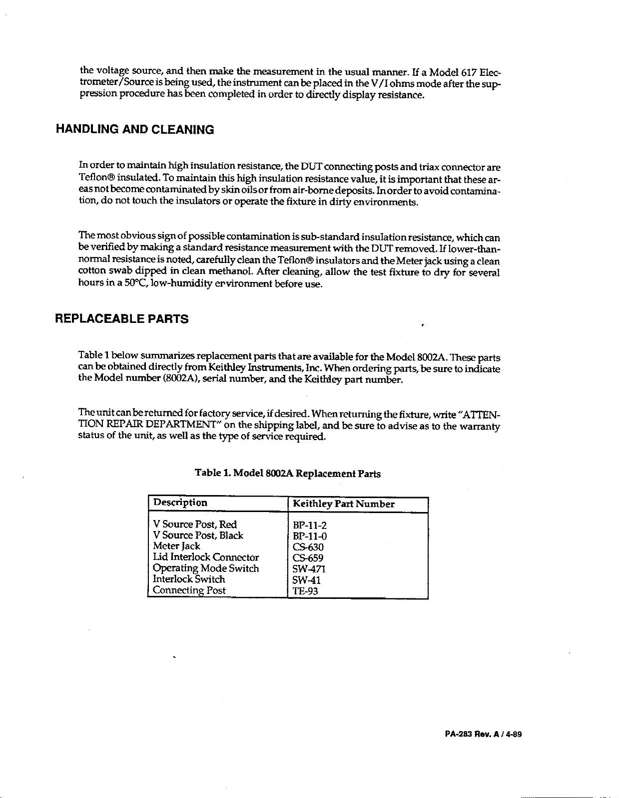
Table 1 below su-ti replacement prta that am avtible for the Mdel 8W~. Th~ ptis
cm be obtained directly fim KeiMey k~ments, hc. men ordefig pafis, b sue to indicate
the Modd number (8W2A), acrid number, and the KeiNey pati number.
Theutit can,kretimd for facto~ =fice, if desiti. men retiting the fixWre, write “A~N~ON ~PO DEP~TMW on the shipping label, md k sure to advise as to the waman~
status of the utit, as well as the type of ace r-quired.
to tinhin high imuktimr resistance, the D~ comecting posts and tri= cmmector are
.
seveml
1Description
Table 1. Model ~~ Replacement Pati
Keitiey Pati Number
PA-2= ReV. A / 449
Page 10

.
Keifiley Im-enk,
Inc.. 28775 Am Road. Clevelad, OH 44139. 216-248-W. F= 216-248-6168. ht@//ww.keitiley. com
WM.Y 1--=- Cb. Y“? an X. Btiltig, Rom 705. N.. 12Yti” Rod, Dewti, Mtia. Btijing, Cb 1W9. 8610-2022886. F= 8610-2022892
KdWey lmt_o”@ SM. BP@. 3 ti~ de, Gaays .91122 PM- -x .31-6-0115155. Fw 31-W117726
KdWey l“st_ak GmbH . Lmdskger Sti 65.82110 Gti”g . 49-89-8493W4 . F=: 49-89-W930759
%Wey Immmti, Ltd. . ~e ~nstm .58 Pom Rd . &a&ng, Bwktim RG30 lU . ti017 W-575%6 . F= &017%-59@69
=tUey Imme”ta SU . Vide S. -mm. 38. 201* ~ao . 39-2483~008 . F= 39-248302274
=itiey =. &bid. BMg.. 7.20.2 Nititi.jti. Stijti-h, To~o la. 81.3.5389.19M. F= 81.3.5389-2068
=tiy --s BV . Avetig fin We,, 49.4202 MS Gotichem . 31-(0)183.635333 . F= 31.(0)183.630821
=tiy timetis W. tis,batisemz 4. 8~ Xbn&ti . 41.1-821* . Fz 41.1 -8~3081
UW.Y bmmti Ttiwm .1, %8-Y. Ftit Sat . Hstihu, Ttiwm, RO.C. .886-35-778462. F= 88 C35-77M55
 Loading...