

Page 1
Page 2
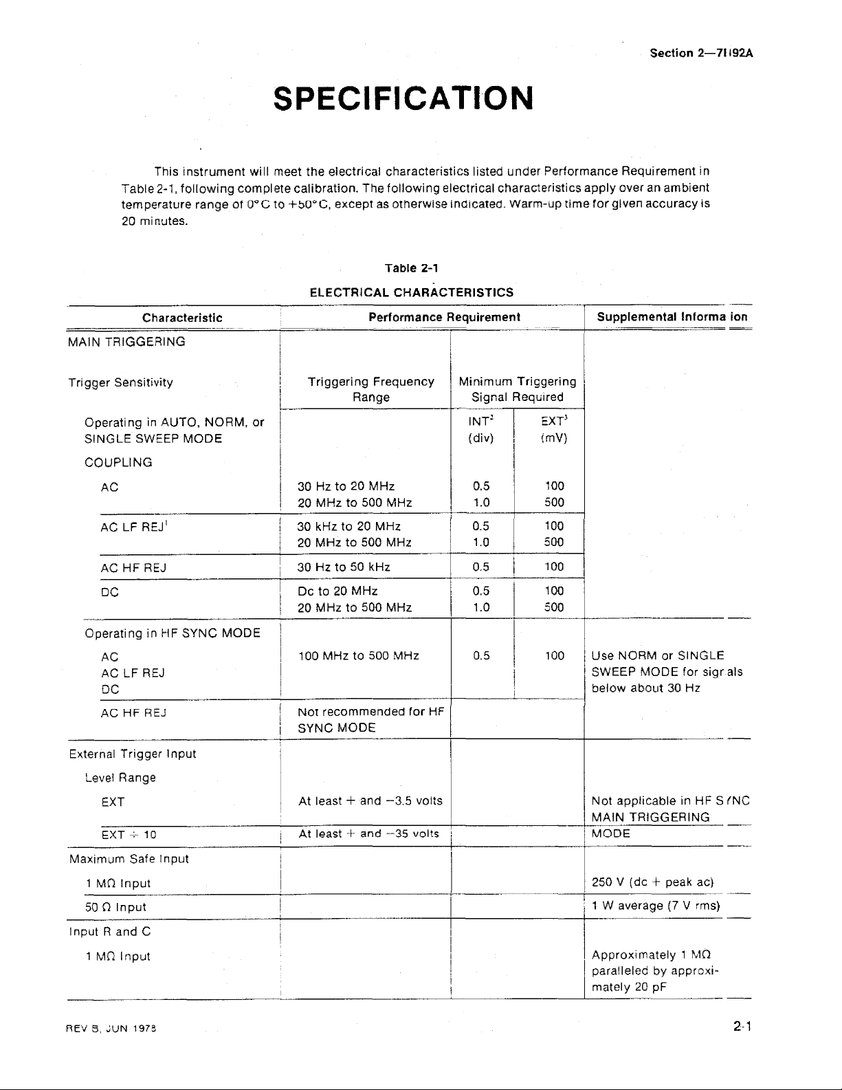
SPECIFICATION
Section
2-71
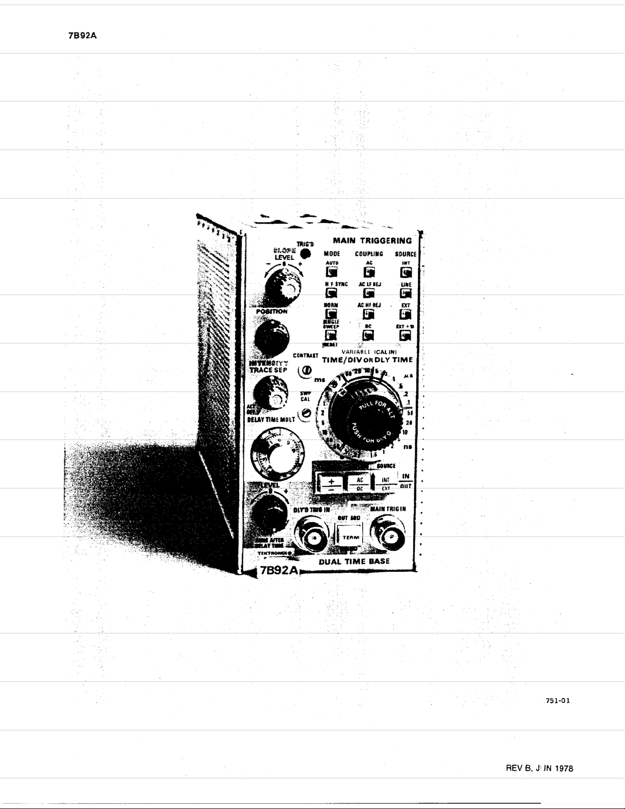
192A
Th~s Instrument will meet
Table
2-1,
temperature range
20 m~nutes.
-
MAlN
Trigger Sensitivity
Operating In
SINGLE
COUPLING
AC
AC
Operating in
Characteristic
TRIGGERING
AUTO,
SWEEP
LF
REJ'
Hf
REJ
D
C
MF
A
C
AC
LF
REJ
OC
the
electrical
following complete calibration. The
of
0°C
to
+5C°C,
except
as
ELECTRICAL
Performance
I
Range
NORM,
MODE
SYNC MODE
or
I
I
I
/
30Hzto20MHz 0.5
20
MHz
to
/
1
30
kHzto20MHz
j
20
MHz
1
30
Hz
I
I
Dc to
1
20 MHz
I
I
I
100 MHz
500
to
500
to
50
kHz
20 MHz 1
to
500
to
500
i
~
characteristics llsted under Performance Requrrement
following
otherwise ~ncllcated Warm-up tlmefor given accuracy
Table
CHARACTERISTICS
MHz
MHZ
MHz
electrical charact~rlstics apply
2-1
Requirement
(div)
I
1
1.0
'
I
I
/
0.5
0.5
:
I
/
1
100
500
100
00
500
over
Supplemental
I
(
1
an arnb~ent
lnforma ion
i
MHz
I
Use NORM or SINGLE
SWEEP
/
below about
MODE
30
for
Hi
in
rs
-
--
-
-
sigr
als
AC
HF
REJ
External Trigger lnput
Level Range
EXT
Max~rnum Safe Input
1
~fl
Inpu:
50
fl
Input
lnput R and
1
hln
REV B LUN
C
lnput
1973
I
Not
recommended
j
SYNC
MODE
I
1
At
least + and -3.5 volts
I
I
i
1
i
--
for
HF
I
I
I
I
I
I
1
Not applicable
MAlN
TRIGGERING
MODE
1
250
V
(dc
T
1
W
average
I
I
I
I
Approximately 1 Mfl
I
paralleled
rnately 20
+
peak ac)
(7
by
approxi-
pF
~n
HF S INC
V
rms)
2-
1
Page 3

50
R
lnput
Characteristic
Table
2-1
{con!)
Periormance
Requirement
.
Supplemental
w-
I
nfor
nation
Resistance
Reflection
Domain)
Trigger J~tter
Internal
Delayed
Trigger
Trigger
Internal
External
or External
Tr~gger~
Sensitivity
Jitter
or
Trigger
Coefficient (Time
ng
External
lnput
50
ps
or
less
at
500
Triggering Frequency
Range
30
Hz
to
20
MHz
20
MHz
to
500
MHz
Dc
to
20
MHz
20
MHz
to
500
MHz
50 ps
or
less
at 500
MHz
MHz
Minimum Triggering
Signal Required
INT'
(div)
EXT
(mvl
50
fl
withrn
0.1
p-p
(using
f
lectonleter)
7%
1
GH
r
Re-
-
Level
EXT
-
-
....---
Maximum
1
Mfl
50
fl
lnput
R
1
MR
50
fl
Resistance
Reflection
(Time
Normal,
Sweep
Trace)
Sweep
Sweep
Rates
Range
Sale
lnput
lnput
and
C
lnput
lnput
Domain)
Alternate
and
input
Coefficient
(Delayed
Delayed
At
0.2
least
ddiv
+3.5
to
0.5
V
to
-3.5
ns/div in
V
27
calibrated steps
250
Y
(dc
-
peak
t
W
average
Approximately
paratleted
mately
59
i3
within
0.1
p-p
by
20
pF
(using
17
appro)
7%
Reflectometer)
Selected
OR
Steps
sequence
by
DELAY
in
a
TIMYD
TIME
1-2-5
V
1
1
Mf
GH
a(
)
rrr
s)
i-
V
switch.
REV
B,
Jl
IN
1978
Page 4

Table
2-1
(cont)
Characteristic
Sweep
Accuracy
Ov5r
Center 8 Div
2
s/Div to 20 ns!Div
Over Any
Center 8 Div
Variable Sweep Rate
lntens~iied Sweep (Delaying
Sweeo
Display)
Sweep
Trace
Rates
2
Div
Portion Within
of
Alternate
Performance
Measc~red
Within
Within
Within
Within
Within
Within
Continuously variable between calibrated
sweep rates
0.2
in
7900-Series Oscilloscope
2%
3%
4%
-
-
5%
5%
10%
s/div to
10
ns/div in
Requirement
Within
Within
/
Within
-
I
Within
/
With~n
Within
23
3%
4?b
5%
-
6%
5%
10%
calibrated steps
Supplemental
Extends
at least
BLE
control internal!
sw~tchable between I
laying and Delayed
Sweeps.
at least
Selected
OR
DLY
Steps in a
Informalion
sweep
0.5
s. VARIA.
Varjabfe
2.51
by
TIME/DI
TI
WE
switcl
1-2-5
rate
rar
seql ence
-
13
(
)e-
ge
\/
.
Swees
Accuracy
Ovcr
Center 8 Div
.2
s
Div
to
20
ns/Div
0;sr
Any
2
Div
Portion Within
8
2iv
Vanaz!e
Trace Separation
Var~acie Time Delay
Dela;
Sweep
ALT
Time
C-''
TIME/DIV Settings
Rate
OFF
Range
Measured in 7900-Series Oscilloscope
Within
Withrn
Within
Con!inuous!y variable between calibrated sweep
rates
lntens~fied sweep can be
div above the delayed sweep
Intensified sweep
played when
is
pulled out and rotated
SEP
2%
3%
5%
control
I
I
/
I
of
the delaying
theT!ME/DIV
dockwlse,
1s
In
ALT
OFF
Within
Within
3%
Withrn
4%
5%
positioned
OR
DELAY
pos~tlon
at
feast
sweep
TlME swltch
and the
3.5
is dis-
f
RACE
-
Extends sweep
least
0.5
trol
internally switch
between Delaying ar
Delayed Sweeps
Allow Intensified
operation
rate
o at
s. Variable i :on-
able
d
--
-
mc
-le
of
2
s;Drv
REV 3 JUN
to
1978
10
ns!Div
0
to
to
1.96
9.8
times :he
s)
DLY
TlME switch
setting
(0
Page 5

Characteristic Performance Requirement Supplemental
-
D~fferent~ai Delay Ttme Measuremen:
Accuracy
Both
50
DELAY
dial
sett~ngs at
greater
One
or
MULT
0
50
ns/Dtv
Both
delay
greater
One
or
than
25
TIME MULT
0
50
or
.
both
DELAY
dial sett~ngs
to
10
ns/D~v
tlmes
than
25
equal
ns
TlME
less
than
to
or
both delay times less Wlth~n
ns
-
--
-
W~th~n
scale
---
W~th~n 0
+5
W~thtn
--
+5
--
ns
ns
Table
2-1
(cont)
--
-
-
-
-
0
75%
of
--
75%
of
1
0%
of measurement
1
0%
of
rneasuremenr
-
-
measurement
measurement
-
-
+O
25°i~
-
+9.5%
1-0.540
+1.0%
-
-
of fult
of
full
of full scale
of
full
scale
--
scale
--
-
--
-
Full scale ts
TlMEiDlV
setting
-
-
15
OR
-
-
--
--
-
lnlorm
---A
t~mes 'he
Dl
Y
TIAE
-
ation
>
--
Delay T~me J~tter
~
I
I
I
1
part
0.2
20
s/Div
ps/Oiv
to
to
50
10
ps/Dlv
I
)
ns/Div
or
delay t~me
TlME
switch setttng)
1
part
or less
delay t~me
TIME sw~tch selt~ng $0.5 ns)
'will
not trigger
-For Internal Triggering only, the specified -3 dB frequency
when the number in the table Is greater than the
'~riggering signal
'fhe specified
is greater than the
on
the sine waves
amplitude
-3
dB
frequency
-3
dB
of
8
div
requirements increased by
of
the Vertical
frequency
Table
2-2
of
the Vertical Syslern.
amplitude
-3
System
ENVIRONMENTAL
Refer
to
the Specification for theassociated oscilloscope. Net We~ght 1 3.062 Ibs (1.372
Jitter spec~f~cation
apply to the f~rst 2%
rnaxtmurn ava~lable
time (DELAY TIME
dial
setting
less
in
50,000
of the maxtmum available
(10
times the TIMWDIV
in
50,000
(10
tlmes the TIME/DIV
or
less (internal),
of
dB
frequency of the Vertical System.
factor
replaces any lrequenciesintheabove table when the number in the
of
:he
or
the Vertical System replaces any frequencies in the above tabi'
of
10
for
EX7
OR
DLY
maxrmurn
3 V or less (external) a!
+
OR
10
operation.
ava~lable
DLY
Table
60
2-3
Hz
or
less
below.
PHYSICAL
I-
kg)
I
See
Fig.
2-1,
Dimensions
Dimensional Drawir
than
lab1
--
do
dl
M
?s
c
f
lay
JLT
I
g
not
the
20)
REV
A,
JI
N
1978
Page 6

OVERALL DIMENSIONS
(MEASURED
AT
MAXIMUM
POINTS)
Specification-
'B92A
I
I
NOTE
DIMENSIONS ARE GIVEN
INCHES
AND
BOTTOM
FIGURE
WITH
TOP
FIGURE
IN
CENTIMETERS.
Fig.
IN
2-1.
Dimensional
drawing.
3EV
C.
JUN
1978
 Loading...