

Page 1

COMMITTED
TO
EXCELLENCE
Tektronix,
P
Box
.O
.
Beaverton,
070-1484-01
Product
Group
Inc
500
Oregon
42
PLEASE
AT
THE
INSTRUCTION
.
97077
CHECK
REAR
O
FOR
THIS
Serial
CHANGE
MANUAL
Number
INFORMATION
.
MANUAL
First
Printing
Revised
FEB
OCT
1983
1972
Page 2

All
Copyright
Contents
without
form
of
v
1972
this
the
Tektronix,
publication
written
permissionofTektronix,
may
Inc
.
not
be reproduced
rights
reserved
in
any
Inc
.
.
Products
byU.S.and
Tektronix,
of
foreign
TEKTRONIX,
registered
trademarks
isaregistered
PrintedinU
are
reserved
.S .A.Specification
.
TEK,
trademarkofTektronixU.K.Limited
Inc.and
patents
SCOPE-MOBILE,
of
INSTRUMENT
Each
instrument
or
stamped
designates
of
the
serial
unique
United
to
States
has a
on
the
chassis.The
the
country
number
each
instrument.Those
have
serial
of
are
six
manufactureisidentified
its
subsidiaries
and/or
pending
and
Tektronix,
SERIAL
number
Inc.TELEQUIPMENT
and
price
NUMBERS
on a
first
manufacture.The
assigned
sequentially
manufactured
unique
follows
as
digits.The
:
patents
change
parW
number
last five
are
covered
.
°
.A
.
privileges
insert,
or
and
in
country
are
tag,
letter
digits
are
the
of
B000000
100000
200000
300000
700000
Tektronix, Inc.,Beaverton,
Tektronix
Tektronix
Sony/Tektronix,
Tektronix
The
Guernsey,
United
Holland,
Netherlands
Ltd
.,
Kingdom,
Japan
NV, Heerenveen,
Oregon,
Channel
Ltd.,London
USA
Islands
Page 3

SECTION
SECTION
1
OPERATING
7A26
Installation
General
7A26
Basic
2
SPECIFICATION
Introduction
Electrical
Environmental
Physical
The
instructions
sonnel
other
to
doso
TA
INSTRUCTIONS
Features
Operating
Front-panel
Applications..
remaining
only
than
.
. . . . . . . ... . . . . . . . . . .
. .
. . . . . . . . . . . . . . . . . . . . . . .
. . . .
Characteristics
Characteristics
Characteristics
portionofthis
.
These
.
To avoid
that called
LE
O
CONTENTS
Information
Controls
. . . . . . .
. .
. .
. . . . ... . . . . . . . . . . . . . . . .
w
servicing instructions
electrical
outinthe
.
... . . . . . .
and
Connectors
. .
. . . . . . . ... .
... . . . . . . ...
. . . . .
.
. . . . . . . . .
WARNING
Table
shock,donot
operating
. .
. .
of
. . . ... . . . . . . . . . . . . . . . . .
. .
. .
. . . . . . . . . . . . . . ... . .
. .
. . . . . . . . . . . . . . ... . . . .
. . . . . . . ... . . . . .
. . . . . . ... . . . . . ... . . . .
... . . . . . ... . . . . . ..2-1
. . . . . . . . . . . . . . . ... . . . . . ...
. . . . . . . . . . . . . . . . . . . . . . . . . . .
. . . . . . ... . . . . . ... . . . . . . . . . .
Contents
are
instructions
lists
the
for
usebyqualified
perform
any
unless
. . .
. .
. . . . .
servicing
per-
servicing
qualified
. .
PAGE
1-1
1-1
1-1
1-2
1-4
2-1
2-2
2-2
SECTION
SECTION
SECTION5
SECTION
SECTION
SECTION
3
THEORY
Introduction..
Block
Diagram
Detailed
4
MAINTENANCE
Introduction
Preventive
Troubleshooting
Corrective
Troubleshooting
Repackaging
CALIBRATION
Introduction
Performance
Test
Calibration
Index
6
ELECTRICAL
Parts
Abbreviations
7
DIAGRAMS
Symbols
8
MECHANICALPARTS
Mechanical
Index
Mechanical
CHANGE
Circuit
Equipment
to
Calibration
Ordering
and
of
Mechanical
OF
OPERATION
. . . . . . ...
. . . . .
Description
. . . . . ... .
Maintenance
. . . . . . . .
Maintenance
Chart
for
Shipment
. . . . . . .
Check
Required
Procedure
PARTS
Information
and
Symbols
AND
CIRCUIT
Reference
Parts
List
Parts
List
INFORMATION
. . . . . . . .
. .
. .
. . . . . . . ... . . . . . . . . . . . . . .
. . . . ... . . . . . . . . ... . . . . . ... . .
. . .
. ... .. . . . .
. . . . ... . . . . . ... . . . . . ... . . . . . . . . ... . . . . . .
. . . . . . . . . . ... . . . . . .
. . . . . . . . .
. . . . . ... . . . . . . . . . . . . . . . ... . . . . . . ... .
. .
. . . . . . . . . . .
. . . . . . . ... . . . . . . ... . . . . . . . . . . . . .
. . . ... .
. . . ... . . . . . . . . . . . . . . . . . . . . . . . .
Procedure
LIST
BOARD
Designators
LIST
Information
Parts
Illustrations
&
TEST
. .
. . . . . . . . . . . . . . . .
. . . ... . . . . . . . . . . . . . . . .
. .
. . . . . . . . . . . . . . . . . . . . . . . . . ... . . . . . .
. .
. . . . . . . . . . . . . . ... .
... . . . . . . . . ... . . . . . . . . . . . . .
. . . . . . . . . . . . . . ... . . . .
. . . . .
. .
. . . . . . . . . . . . . . ... . . . . .
. .
. . . . . . . . . . . . ... . . . . ... . . . .,. . . .
ILLUSTRATIONS
EQUIPMENT
. . . . . . . . . ...
.
. . . . . . . . . . . .
. .
. . . . . . ... . . .
. . . ... . . . . . .
. . . . . . . .
. . . . . . . . . .
. .
. . . . . . .
. .
. .
. .
3-1
3-1
3-1
4-1
4-1
4-1
4-3
4-5
4-8
5-1
5-1
5-1
.
5-3
5-3
REVSEP
1981
Page 4

Fig.1-1.7A26
Dual
Trace
Amplifier
.
Page 5

Section
1--7A26
7A26
Features
The
7A26
Dual
Trace Amplifier
for
use
7A26
and
gain
to
correspond
Channel2canbeinverted
Installation
The
can
be
7000-series
in
vertical
and
lower
fully
insertit.
oscilloscope
at
the
against
To
inscribed
7A26
the
7A26
TEKTRONIX
with
isadual-channel
compensation
to
the
PRELIMINARY
is
7A26
bottom-left
the front panel.See
remove
will
calibrated
installed
plug-in
rails
with
out
in
oscilloscopes,
compartments.To
of the
The
front
when
the
corner
7A26,
the
the unit
unlatch.Continue
of the
oscilloscope
any
7A26
OPE
7000-Series
wide-bandwidth
circuits
settingofthe
7A26isfully
are
for
differential
INFORMATION
and
ready
compartment
butisintended
with
the
willbeflush
of the
Fig.1-2
pull
on
identification
pullingonthe
.
ATIN
plug-in
automatically
7A26
.
unitisdesigned
Oscilloscopes.The
amplifier.Internal
VOLTS/DIV
measurements
for
use
as
TEKTRONIX
of
for
align
install,
oscilloscope
the front of the
with
inserted,
willbein
the
latch
"7A26")
switched
switch
.
received.It
principal
and
latchtoslide
the
tracks
the
(which
and
use
upper
and
latch
place
the
INSTRUCTIONS
used.For probes
without
Vertical
.
switch
signal
torofthe
should
front-panel
The
control
screwdriver
Connectors)
clockwise,
GAIN
as
the
divisions,
Input
is
switches
type
the
readout,
Gain
To
check
to 10
from
be exactly four
GAIN
knob
controlisengaged,
the
knobisturned.Turn
screwdriver
then
Coupling
The
Channel1and
allow
of display
coupling
to
see
Check
the
gain
mV
and
oscilloscope
the
channel
GAIN
adjustment
and
(see
.
'Turn
until
the
until
remove
choice
a
desired
use
to
for
turning
Fig.1-3
.
used with
be
Tektronix,
the
and
Adjustment
either
of
being
the
GAIN
the
the
channel,
connect
exactly four
is
Channel2coupling
and
40
calibrator
checked
divisions
engaged
the
knob
Front
knob
control
the
vertical
the
deflectionisset
screwdriver
of
input
the applied
amplifier
Inc.catalog
millivolts,
The
.
.
divisionsofdeflection
by
pressinginthe
clockwise,
is
deflection
GAIN
.
coupling
units
.
VOLTS/DIV
set
the
1
input
to the
vertical
If
not, adjust the
with
Panel
narrow-blade
a
Controls
then
engaged.When
will
control
to exactly
(AC-GND-DC)
methods.The
signal
will
deflection
knob
determine
with
or
kilohertz
connec-
GAIN
and
counter-
the
change
with
four
.
GENERAL
Introduction
single-trace
For
amplifier
DISPLAY
1orCH
appropriate
operations
Signal
connecting
attenuation
the
operating
be
equipped
probe
automatically
the
channels
2
Connections
general,
In
circuit
Any
TEKTRONIX
used with
connects
actual
MODE
and
connecting
input.In
using
CH1only
probes
a
signal to
probe
under
conditions
TEKTRONIX
with
readout.'The
toacircuit
corrects
deflection
OPERATING
operation,
can be
and
TRIGGER
the
offer
offersahigh input
test
.
probe,
the
factor
either
independently
used
signal
the
discussions
apply
the
the
input
perform
to
withareadout
readout
in
readout
at
most
7A-series
the
INFORMATION
of the
two
by
SOURCE
equally toCH2
the
displayedonthe
tip
to be
observed
to follow,
convenient
of the
impedance
very
close
amplifier
coding
amplifier
of the
switchestoCH
7A26
coding
identical
setting
the
the
to
single-trace
.
only
of
means
A
10X
.
and
allows
normal
to
ring
can
units
ringonthe
which
unit
CRT
being
probe
DC
and
signals
.
Release
coupling
below about
square
are
The
DC
component
AC
signals
probe)
these
to
Fig.1-2
position
the
signal.It
of
waves
attenuatedintheACposition
latch
.
30
hertz
with
low-frequency
must
must
be
also
(ten
used
display
to
used to
be
hertz with
components
.
the
display
a
10X
as
Page 6

Operating
CH
Provides
CH2POLARITY
Provides
CH2display
Instructions-7A26
1
Input
Connector
signal
means
.
connectiontoCH1.
of
inverting
the
CH1POSITION
Controls
trace
trace
---,
position of
and
.
"ADD"
the
display
CH
mode
1
Selects
signal
Selects
.
source
the
mode
of
of
operation
the
trigger
.
Providesameansoflimiting
upper
bandwidth
CH2POSITION
Controls
trace
only
Deflects trace
for trace
ments
with
readout
"IDENTIFY"
.
position of the
IdisabledinADD)
about0.2
identification.In
Readout,
with
also
the
.
division
replaces
the
CH
2
.
instru-
word
CH2Input
Provides
Connector
signal
connectiontoCh2.
AC-GND-DC
Selects
mode
.
(sameasCH
signal
Provides
uncalibrated
calibrated
When
pushed
panel
calibration
Selects
factors
V/Div
;
sequence
input
continuously
settings
steps
.
the
VARIABLE
in,
it
screwdriver
from
ten
.
coupling
becomes
of deflection factor
calibrated
5
mV/Div
steps
1)
variable
between
control
a front
adjustment
deflection
to
in
a
is
for
.
5
1-2-5
Fig.1-3.7A26
front-panel controls
and
connectors
.
Page 7

In
the
AC
coupling
signalisblockedbya
coupling
DC
precharge
use
probe
coupling
input
input
inputs
to the
VOLTS/DIV
determined
of the
the
tion
switch
calibrated
settings
switch.With
clockwise
uncalibrated
least12.5
source
factor
control
CH
displayed
Thisisparticularly
when
POLARITY
the
same
will
positive-going
on
move
DISPLAY
CH1inputortheCH2 input
switch to the
position
component
feature
this
feature,
the
circuit
to
capacitor to
The
GND
position
of
the
amplifier
connectors.However,
are
not
grounded,
signal
source
and
The
amount
probe,
setting
factors
apply
The
VARIABLE
can
.
2
POLARITY
The
CH
differential
+UP
polarityasthe applied
move
the
CRT
the
For
of
by
the
the
of the
indicatedbythe
only
(CAL
between
the
and
the
vertical
volts/division.By
to the input
be
POLARITY
2
waveform
switch has
position,
the
CRT
waveform
in
inverted
trace
down
MODE
single-trace
corresponding
position,
capacitorinthe
provides
much
larger
shouldbeused with
first
set
the
wait
and
charge.Then
provides a
without
and
.
VARIABLE
vertical
IN)
the
set
measurements
deflection
signal
amplitude,
setting
of the
VARIABLE
when
the
position
control
calibrated
VARIABLE
VOLTS/DIV
deflection
connector,
within
Switch
switch
the
of
useful
two
the
displayed
traceup.Inthe
at
form
.
Switch
operation,
the
DC
component
input
circuit.The
the
best
displayofsignals
than
the
AC
components.The
large
DC
GND
coupling
the
the
VARIABLE
.
provides
applyingacalibrated
the range
signal
in
added
positions,
signal
theCH2
andapositiveDCvoltage
position:CH1orCH2
to
about
set
ground
externally
signals
same
Controls
producedbyasignal
the
VOLTS/DIV
control.Calibration
settings
variable,
steps
control
setto5
factorisextended
any
may
appliedtotheCH2
operation
aretobe
+UP
waveform
andapositiveDCvoltage
input
apply
the
and
set
.
two
seconds
the
couplingtoAC
referenceatthe
grounding
connected
DC
load
attenuation
VOLTS/DIV
of the
controlisin
of the
fully
volts/division
specific
of
the
be
usedtoinvert
made.The
and
will
INVERT
willbedisplayed
signal
the
DISPLAY
the
of
AC
with
inputs.To
for
to the
presented
factor
and
deflec-
counter-
to
voltage
deflection
input
the
7A26
CH
have
position,
to the
MODE
.
the
the
the
the
the
will
Connect
is
switch,
uncalibrated
VOLTS/DIV
VARIABLE
of
INVERT.In
either
the
the
Operating
To
display
signalisalso
a
desired
the
.
MODE
channel1and
Although
CHOP
rates
rates
tible
switch
signals,
is
at
signal
both
deflection
However,ifthe
settodifferent deflection
is
the
determined
applied
positioning
POSITION
switched
hertz
mode
about
.
TRIGGER
2
switch
appliedtothe
display of
a
switch
applied to the
display of the
switch, the
channel
appropriate
Alternate
switch
mode
below
alternate
.
Add
Mode.The
canbeusedtodisplay
for
.
The
VOLTS/DIV
difficulttodetermine
voltage
ChopMode.The
MODE
non-repetitive
on
switch
rate
provides
0.5millisecond
1.The
CH
provides
CH2.
providesatrigger
MODE
the
setting
signal in
a
applied to the other
by
CH1orCH2 position
Mode.The
producesadisplay
channel2with each
the
ALT
providesamore
about0.5
mode
common-mode
overall
factor
CH1and
amplitude
accurately
to
one
channel
of the
control
producesadisplay
between
(controlled
the best
phenomena
SOURCE
CH
a
CH1input
the
signal
The
CH2position
CH
signal
.Inthis
trigger
of
one
channel independently
setting
the
DISPLAY
ALT
positionofthe
mode
canbeusedatall
satisfactory
millisecond/division.At slow
switching
ADD
position
the
rejectiontoremoveanundesired
deflection factorinthe
switches
indicatedbyeither
traceiscontrolled
only
channels
1
trigger
2 input
position
signal
the
set
to the
CH2VOLTS/DIV
factors,
the
from
of the
onlyifthe
is
known.In
.
CHOP
by
positionofthe
applied to the
applied
DISPLAY
position
at
mainframe).In
displayatsweep
/division
is
to be
Switch
signal
connector.This providesastable
of the
signal
connector.This providesastable
to the
of
for
the
time-base
Instructions-7A26
channel,
which
becomes
of
sum
CRT
resultant
approximately
or
displayed
obtained
obtained
the
MODE
simply
select
MODE
.
alternates
sweep
the
DISPLAY
or difference of
same
VOLTS/DIV
the
resultant
display.In this
amplitude
the
by
of the
whichiselectronically
general
whenever
TRIGGER
CH1input
TRIGGER
CH2input
TRIGGER
switch.The
switch to
DISPLAY
on the
sweep
displayatsweep
visually
ADD
mode
positionisthe
switches
amplitude
display
of
the
ADD
the
channel
DISPLAY
a
the
rates
slower
dual-trace,
.
from
the
connector
the
from
connector
unitisdependent
when
between
rates,
sweep
percep-
MODE
switch
can
signal
mode,
500
CHOP
SOURCE
signal
SOURCE
SOURCE
trigger
the
CRT
the
two
with
are
case,
be
kilo-
than
signal
a
.
.
1
.
.
REV,B,MAR.1975
Page 8

Operating
source
as
follows
Instructions-7A26
for
each
:
MODE
CH
1
CH
2 Channel
ADD
CHOP
ALT
Trace
Identification
When
deflected
This
featureisparticularly
Channel
Algebraic
Algebraic
Alternates
IDENTIFY
the
about 0.2divisiontoidentify
displayed.When
ments
replaced
BW
with
with
Switch
readout,
the
Providesameans
FULL:Allows
MHz
:
Reduces
20
megahertz
.
positionofthe
TRIGGER
l
2
sumofchannel1and
sumofchannel1and
between
buttonispressed,
useful
the
IDENTIFY
the
word
"IDENTIFY"
of
limiting
the
7A26
to
the
upper
bandwidthofthe
DISPLAY
SIGNAL
MODE
SOURCE
switch
channel
channel
channel1and
when
multiple
the
channel
the
7A26
traces
trace
buttonispressedoninstru-
deflection
factor
readout
.
the
upper
bandwidth
operateatfull
bandwidth
7A26toabout
2
2
trace
are
.
20
is
For
low-frequency
theDCpositiontoprevent
4.Set the
divisionsofthe
VOLTS/DIV
waveform
NOTE
signals
vertically
below
about30hertz
attenuationofthe
switch
to
display
.
signal
about
use
.
five
2
5.Set
display.Set
displays
the time-base
the time-base
several
cyclesofthe
Triggering
controls
unit toasweep
waveform
forastable
rate
which
.
is
.
is
.
Turn
below
the
7A26
waveform
the
center horizontal
6
.
portionofthe
lines
waveformiswithin the
Position control,
peaks
lies
near
7.Measure
peak.Check
in
the
CAL
the
the
that
IN
position
move
center
divisionsofvertical
VARIABLE
the
POSITION
coincides
viewing
the
displaysoone
vertical
.
controlsothe
with
oneofthe
line,
and
area.With
line
(see
Fig.1-4)
deflection
(VOLTS/DIV)
lower
graticule
the
topofthe
the time-base
of
the
upper
.
peak-to-
control
is
NOTE
BASIC
General
The
following
techniques
the
associated
These
applications
application
individual
for
many
applications
your
local
information
for
making
TEKTRONIX
must
be
measurements.This
TEKTRONIX
assistanceinmaking
instrument
Peak-to-Peak
To
following
1 .
2.Set the
switches
make
procedure
Apply
to
.
Voltage
peak-to-peak
the
signaltoeither
DISPLAY
display
the
APPLICATIONS
basic
are
not
adapted
not
described
Field
specific
Measurements
:
MODE
channel
describes
measurements
the
witha7A26
oscilloscope
describedindetail
the
to
instrument
requirementsofthe
can
in
this
manual.Contact
Office
or
representative
measurements
(AC)
voltage
measurements,
input
connector
and
TRIGGER
used
.
procedures
and
time-base
since
alsobeused
with
use the
.
SOURCE
and
and
each
for
this
.
This
ments
than
peaktopeak
8.Multiply
VOLTS/DIV
of
the
probeifused
technique
between
the
switch
can
also
be usedtomake
two
pointsonthe
.
deflection
measured
setting.Include
.
Position
Centerline
the
To-
waveform,
in
step
attenuation
T
measure-
rather
7 by
factor
the
3.Set the
coupling
switchtoAC
.
Fig.1-4.Measuring
the
peak-to-peak voltage
of a
waveform
.
Page 9

X
EXAMPLE
deflection
attenuator
Volts
PeaktoPeak
Substituting the
The
peak-to-peak
:
is4.5
probe,
Volts
Instantaneous
To
measure
proceedasfollows
1.Connect
2.Set the
switches
to
the
the
DISPLAY
display
Assume
vertical
deflection
(divisions)
given values
Peak-to-Peak
that
divisions
and
the
voltageis45
Voltage
level
DC
:
signaltoeither
the
channel
the
peak
(see
Fig.1-4)
VOLTS/DIV
VOLTS/DIV
setting
:
= 4.5X1X
volts
.
Measurements
given
at
a
input
MODE
used
and
.
peak
to
switchissetto1V.
vertical
usinga1OX
probe
attenuation
X
factor
10
(DC)
pointona
connector
TRIGGERSOURCE
waveform,
.
7.Measure
ence
line
levelisto be
measurement
8.Establish
2
POLARITY
the
reference
9.Multiply
VOLTS/DIV
probe,ifused
EXAMPLE
divisions
3
.6
reference
of0.5V.
Using
the
Instantaneous
Voltage
Substituting the given values
the
distanceindivisions
and
the point on the
measured.For
is
between
the
switchinthe
lineispositive
the distance
setting.Include
.
:
Assume
(see
line
usinga1OX
formula
vertical
= distanceXpolarity
(divisions)
the reference
polarity
the
Fig.1-5)
:
Operating
waveform
example,
of the
+UP
position,
.
measured
the
vertical
and
the
probe
withaVOLTS/DIV
XDIVX
:
Instructions-7A26
between
at
line
and
waveform
in
attenuation
distance
waveform
VOLTS/
setting
the
refer-
the
which
in
Fig.1-5
A
point
With
.
any
step 7 by the
factor of the
.
the
above
point
measured
is
above
setting
probe
attenuation
factor
DC
the
CH
is
the
3.Set the
divisions
4.Set the
trace
to the
the
voltageisnegative
trace
to the top
control
line
position
display.Set the
display
after
To
measureavoltage
other
4.Set
step
reference
position
5.Set the
can
6.Set the time-base Triggering controls
of the
of the
than
be
.
VOLTS/DIV
waveform
coupling
bottom
this
ground,
the
voltage
the
trace
coupling
checked
waveform
graticule
with
graticule
reference
coupling
to
to the
at
time-base
switch
.
switch
make
switch toDC.
any
.
to
GND
lineorother
respect to
line.Do
line
NOTE
level
the
not
has
been
with
the
following
switchtoDC
input
reference
timebyswitching
sweep
to
respecttoa voltage
line
rate
display
ground,
move
established
connector.Then
.
Theground
and
position
reference
position the
the
changes
and
apply
to the
forastable
for
an
about
POSITION
.
reference
optimum
five
the
line.If
to
the
GND
Instantaneous3.6X
Voltage
The
instantaneous
Fig.1-5.Measuring
reference
.
voltageis18
instantaneous
+1
volts
voltage
X0.5
.
V
X
with
respecttosome
10
Page 10

=
Operating
ComparisonMeasurements
arbitrary
by
comparing
use for the
tate calibrationofequipment
does
tion.The
arbitrary
correct
divisionsofdeflection.The
how
measurements
uponaspecific
Set the
of
the
controltoproduceadisplay
vertical
VARIABLE
Instructions-7A26
In
some
applicationsitmay
unitsofmeasurement
the
VOLTS/DIV
unknown
comparison-measurement
not
produce
adjustment
unitsofmeasurement
adjustment
to
establish
To
establishanarbitrary
1.Connect
time-base
signal
2.Set the
divisions
arbitrary
.
reference
the reference
unit
.
VOLTS/DIV
control
switch
signalstoa
an
exact
willbeeasier
is
indicated
amplitude,
sweep
in
amplitude.Do
after
be
desirabletoestablish
other
than
.
This
is
particularly
reference
techniqueisto
where
the desired
number
following
unitsofmeasure
vertical
signal
switch
obtaining
of
and
are
established
by
an
procedure
deflection
proceedasfollows
to the input
ratetodisplay
and
whichisan
the
those indicated
useful
when
amplitude.One
facili-
amplitude
divisionsofdeflec-
more
accurate
so that the
exact
for
the
exact
not
desired
number
comparison
factor
connector
several
VARIABLE
number
change
deflection
of
describes
based
:
cycles
of
the
6.Measure
calculate
following
Amplitude
if
volts,aVOLTS/DIV
control
divisions.Substituting these
sion
.
peak
vertical
using
.
the
formula
Signal
EXAMPLE
adjusted
factor
Vertical
Conversion
Then
withaVOLTS/DIV
amplitude
deflection
the
signal
Signal
Amplitude
formula
Factor
the
vertical
amplitude
.
VOLTS/DIV
:
Assumeareference
to
of an
amplitude
of the
setting
setting
provideavertical
(step4):
4X5V
unknown
of five
divisions
formula
2
V
X1.5X5 =15volts
deflection
unknown
X
conversion
of 5Vand
valuesinthe
30
V_
setting
in
signal
vertical vertical
factor
signal
amplitudeof30
the
deflectionoffour
vertical
of 2 V, the
signal
which
can
be
determined
(step6):
divisions
using
X
deflection
(divisions)
VARIABLE
peak-to-
produces
and
the
conver-
a
by
3.To
establishanarbitrary
the
amplitude
accuratelyatany
amplitude
not
known,
VOLTS/DIV
4.Divide
by
the
establishedinstep
switch.Thisisthe
Vertical
Conversion
Factor
5
.
To
disconnect
signal
to the
toasetting
make
an accurate
VARIABLE
of
of the
it
can be
controlissetinstep 2
the amplitude
product
measure
the reference
input
that
control
vertical
an
unknown
settingofthe
reference
of the
2
vertical
the
connector.Set the
provides
.
signal
measured
the
of
vertical
the
and
measurement.Do
settingofthe
conversion
__amplitude
vertical
deflection
(divisions)
amplitude
signal
sufficient
signal
VOLTS/DIV
must
before the
.
reference
deflection
factor
reference
of
and
connect
vertical
deflection
can
be measured
be
known.If it is
signal
VOLTS/DIV
.
signal
(volts)_
VOLTS/DIV
X
an
unknown
the
VOLTS/DIV
deflection
not
readjust
factor
switch,
VARIABLE
(volts)
(divisions)
switch
setting
signal,
unknown
switch
the
the
so
to
Dual-TracePhase
Phase
comparison
frequency
7A26.This
be
system
procedure
1.Set the
position,
2.Set the
general,
ALT
TRIGGER
3.Connect
the
or
probes
connect
4.If
POLARITY
may
if
so,
canbemade
method
used
up
to
.
make
To
CH1and
depending
CHOP
is
more
SOURCE
comparison
which
the
signals
the
signals
switch to
beofopposite
take
this
the reference
into
Difference
between
of
the
frequency
the
on
the
DISPLAY
is
more
suitable
to
signal
to the
have
similar
to the
areofopposite
invert
polarity
accountinthe
Measurements
two
using the
phase
comparison,
CH2coupling
typeofcoupling
suitable
for
CH1.
input
dual-trace
difference
limit
MODE
for
high
signal
CH2input.Use
time
connectors
the
channel
dueto180°phase
final
signals
to
low
frequencies.Set the
to the
delay
polarity,
of the
feature of the
measurement
of the
switchestothe
ALT
calculation
oscilloscope
use the
2 display.(Signals
following
desired
.
or
CHOP.In
frequencies
CH1input
coaxial
characteristics
.
set
the
difference
.)
same
can
same
and
and
cables
to
CH
2
;
Page 11

5.Set the
controls of the
five
about
6.Set the
about
controls
one
7.Center
POSITION
8.Adjust
one
cycle of the reference
horizontal
linesofthe
graticule
450/division).The
degreesas45°/division
9.Measure
sponding
VOLTS/DIV
two
divisionsinamplitude
time-base
cycle of the
forastable
the
waveforms
controls
divisions
represents45°
points
.
the
time-base
graticule
sweep
the horizontal
the
on
switches
channelssothe
.
unit toasweep
waveforms.Set the
display
.
on
the
Variable
signal
between
(see
Fig.1-6).Each
of the cycle
rate
.
waveform
the
can
difference
.
and
displays
graticule
Time/Div
occupies
second
(360°-:8
now
VARIABLE
the
are
rate
which
with the
control
exactly
and
tenth
divisionofthe
be
statedinterms
between
equal
and
displays
Triggering
7A26
until
eight
vertical
divisions
corre-
Operating
Using the
Phase
Substituting the given
The
High
made
Variable
increase
switch.Set the
=
magnified
of
previouslybythe
the
= 4.50
Fig.1-6
horizontal
formula
Difference=
Phase
phase
differenceis13.50
Resolution
More
accurate
by
increasing
Time/Div
the
sweep
sweep
EXAMPLE
Magnifier,
/division.Fig.1-7
:Ifthe
the
but
difference
:
horizontal
difference
(divisions)
values
:
Difference=0.3X 45
.
Phase
Measurements
dual-trace
the
control).One
Magnifier
rate
amount
magnified
with
rateiswith
by
the
of 3
phase
sweep
rate
to
dividing
of
sweep
sweep
rateisincreased10times
sweep
shows
Magnifier
divisions,
the
Instructions-7A26
sweep
X
(degrees/division)
0
measurements
(without
the
of
the
X10
the
magnification
rateis450/division
same
set
the
changing
easiest
time-base Magnifier
and
determine
sweep
rate
signalsasused
to
X10
differenceis:
phase
rate
can
ways
obtained
.
With
.
be
the
to
the
by
=10
in
a
10.Multiply
450/division
difference
division
1-6
.
EXAMPLE
withasweep
.
to
:
the
measured
obtain
Assume
rateof45°/divisionasshown
distance
the
exact
a horizontal difference of 0
(in
amount
divisions)
of
phase
in
Fig
by
Phase
Difference= difference
Substituting
.3
.
The
phase
the given
Phase
difference
horizontal
X
(divisions)
values
:
Difference=3X4.50
is13.5°.
magnified
sweep
rate
(degrees/division)
Fig
.
Measuring
1-6
.
phase
difference
between
two
signals
Fig.1-7.High
.
magnifier
.
resolution
phase
measurement
using
time-base
Page 12

Operating
Instructions-7A26
Common
The
signals
undesirable
common-mode
1.Set the
and
2.Connect
undesired
3.Connectasignal
the
in
Fig
cancel
to
signal
1
4.Set
AC,
5.Set the
equalinamplitude
Mode
ADD
feature of the
which
components
DISPLAY
the
TRIGGER
informationtotheCH1
CH1signaltothe
.
1-8aline-frequency
out
the line-frequency
.
both
depending
VOLTS/D
Rejection
contain
rejection.The
SOURCE
the
signal
similartothe
CH2input
coupling
on
switches
the applied
IV switches
.
7A26
can be used to
undesirable
can
procedureisas
MODE
switchtoMODE
containing
signalisconnectedtoChannel
signal
components.These
be
eliminated
switchtoALT
both
the
input
connector
unwanted
connector.For
component
to the
same
.
so the
signals
follows
or
.
desired
.
portion
example,
of the
setting,DCor
are
display
through
:
CHOP
and
of
2
Channel
about
6.Set the
2
POLARITY
signals
7.Adjust
VARIABLE
common-mode
only
the
EXAMPLE
shown
unwanted
corresponding
2
(Fig.1-8B).Fig.1-8C
signal
as
The
signal
superimposed
used.A DC
Channel2canbeused
signal
appliedtoChannel1.
DISPLAY
switch
areofopposite
the
control
signal.The
desired
in
displayed
above
portion of the
:
An
Fig.1-8.The
line
frequency
line
frequency
when
procedure
voltage of the
Channel
MODE
to
INVERT
polarity
for
example
onsome
.
2
maximum
signal
channel1signal
of
signal
applied
components
signalisconnected
shows
common-mode
can
alsobeused
DC
proper
to cancel out the
switchtoADD.Set the
so
the
common-mode
VOLTS/DIV
cancellation
which
this
mode
to
the
desired
level
when
polarity
switch
of the
remains
Channel1contains
rejection
DC
should
.
of
operation
(Fig.1-8A).A
to
Channel
portion of the
is
used
for
examining
DC
coupling
applied to
portionofthe
CH
and
.
be
is
a
is
Fig.1-8.Using
Channel1signal
frequency
(C)
component.(B)
Resultant
CRT
the
ADD
contains
display using
mode
for
desired
Channel 2
common-mode
common-mode
information
contains
rejection.(A)
along
line
frequency
rejection
with
.
line-
only
.
Page 13

Introduction
The
ambient
temperatureof+20°C
following
electrical
SPECIFICATION
characteristics
+30
to
°C,
and
are
valid
over
the
afterafive-minute
TABLE
Electrical
stated
warmup
2-1
environmental
unless
otherwise
range
for
noted
instruments
.
Section
calibratedatan
2-7A26
Characteristic
Deflection
GAIN
Frequency Response
Maximum
Factor
Calibrated
Deflection
Uncalibrated
Range
BW
FULL/20
Upper
Bandwidth
R
isetime
Input
Range
Factor
(VARIABLE)
Voltage
MHz
Accuracy
Gain
Match
Performance
5
mV/Div
sequence
Within2%with
20
Depends
MHz
.
gain
upon
to5V/Div;ten
Requirement
GAIN
adjustedat10
within1%full
oscilloscope
gain
used
steps
.
.
in a
1,2,5
mV/Div
Supplemental
Aberrations;5mVand 10mV.+4.0%,-4.0%,
nottoexceed6%P-P
total
to
exceed8%.
.
Continuously
extends
per
division
Permits
calibrated
scopes
See the
or
the
20
MHz,±3MHz
21 ns
variable
deflection factor to
.
adjustmentofdeflection
operation
.
oscilloscope
Tektronix,
current
maximum
.
.
Inf
between
with
all
mainframe
Inc.catalog
ormatio
n
;
20mVto5V,
calibrated steps
at least12.5
7000-series
specifications
factor
oscillo-
.
not
;
volts
for
DC
Coupled
AC
Coupled
REVDNOV
1979
250
volts,
volts
peak-to-peak
less
.
500
volts,
volts
peak-to-peak
less
.
50:1display
(DC+Peak
maximum,
(DC+Peak
maximum,
ratioupto
AC);AC
AC);AC
200
component500
one
kilohertz
component
one
kilohertz
megahertz
or
500
or
.
Page 14

Specification-7A26
SN
8208879-below
SN
B208880-up
Capacitance
SN
B208879-below
SN
8208880wp
1ME22%
1
MA2%
20pF±02pF
22pF±02pF
.
.
Overdrive
Delay
Time
Common
Display
Trigger
Recovery
Mode
Modes
Source
Difference
Rejection
Selection
Time
Between
Ratio
Channels
At
least10:1,DCto50MHz
Channel1only
Dual-trace, alternate
Added
Dual-trace
Channel
Channel1only
Follows
Channel2only
Refer
to the
.
algebraically
chopped
2 trace
only
.
DISPLAY
.
Environmental
specification
between
.
between
.
MODE
TABLE
-----------
.
channels
channels
selection
2-2
Characteristic
for
the
associated
0.1msorlesstorecovertowithin
after
removalofoverdrive
divisionsor-75
drive
signal
200
picosecondsorless
.
.
.
mainframe
.
duration
divisions
.
.
one
signalofupto+75
regardlessofover-
division
Size
Weight
2-2
Fits
all
2_Pounds
TABLE
7000-series
9Ounces1.2
__
2-3
plug-in
0
_
compartments
kiloqra
ams~
.
.
NOV
REV
1979
B
Page 15

WARNiNG
Page 16

Section
3-7A26
Introduction
This
section
circuitry
begins
diagram
is
interconnections
the
stages
Diagrams
following
relationship
variable gain
Amplifier
gain
usedinthe
withadiscussion
shown
described
relationship
Complete
The
setting,
in detail
.
section.Refertothese
circuit
.
Channel1Amplifier
provides
variable
of the
in
the
between
of the
schematics
description
BLOCK
control,
signal
gain
manual
7A26
amplifier.The
of the
Diagrams
using the
stagesineach
front-panel
of
DIAGRAM
and
trace
polarity
control,
THEORY
containsadescriptionofthe
description
7A26
instrument
section.Then,
block
controlstothe
each
circuit
schematics
for
circuit
positioning.The
inversioninaddition to
and
using the
diagram
major
are
throughout
electrical
provides
trace
positioning
each
show
to
circuit
individual
given
values
gain
Channel
circuit
in
setting,
OF
block
the
and
the
the
and
.
OPERATION
The
provide
lines,
output
limits
Amplifierisconnected
the
to the 7000-series
2
differential
from
.
the
The
output
interface
Readout
DETAILED
The
CH1and
with
which
CH1is
Display
These
upper
the
includes a
and
signal
each
channel,toa
stages
also
frequency
of the
connector
encoding
exception
describedindetail
circuitry
.
CIRCUIT
CH2amplifier
POLARITY
Trigger
Display
.
of
Channel
outputs
containabandwidth
responseto20
to the oscilloscope
NOTE
the
for
common
and
Trigger
usedinthe
DESCRIPTION
circuits
CH2GAIN
inverting
throughout
switch
the
signal
display
limiter
megahertz
Channel
mainframe
7A26isstandard
are
identical
stage
circuit.Only
this
discussion
amplifiers
and
trigger
and
trigger
that
.
switch
02450,
via
.
The
signal tobedisplayedonthe
CH1or
the
is
selects
passed
10
connectorispassed
ation.When
position,
other
Amplifier's
balance
Gain
adjustments
output
tioning
functions
1,
Channel2.
CH2INPUT
input
coupling
selected,
When
mV
Overall
with
to the
the correct
to the
Input
the
VOLTS/DIV
positions,
the
the
2X
positions
gain
adjustments
GAIN
Amplifier.Variable
are
also
of the
the
Gain
circuitry
are
controlled.Channel2is
exception
connector.The
switch,
amount
Source
the
through
VOLTS/DIV
Gain
of the
is
and
where
where
attenuators.The
of
attenuation
Follower
switchisset
signal
connected
the
attenuators
Amplifier
VOLTS/DIV
reduced
are
VARIABLE
controlledinthe
Amplifierisconnected
of the
by
includedinthe
Balance
the
POSITION
polarity
CRT
is
applied
signal
passes
through
the
appropriate
VOLTS/DIV
and
.
to the 5
switchissetinthe 5
operatesatfull
switch, the
two.Internal gain
Amplifier
2X
gainisadjustedinthe
and
high
Gain
and
identicaltoChannel
inversion
coupling
the
signal
mV
to the
without
Amplifier.The
INPUT
attenu-
gain.In
2X
frequency
to the
IDENTIFY
function
to the
switch
and
mV
Gain
and
.
Posi-
is
all
in
AC-GND-DC
Input
signals
AC-coupled,
S100A
showing
When
INPUT
the
C10
signal
opens
amplifier
without
INPUT
AC-GND-DC
GND
Input
determined by
S100B.The
divisionofCRT
isacam-type
the
the
AC-GND-DC
signalisconnected
AC
position,
The
.
capacitor
from
the
signal
to
the
needtodisconnect
connector.Resistor
position
Attenuator
The
effective
Switch
connected
DC-coupled,
operationisgivenonthe
the
passing
path
ground.This
switch, allows
.
overall
the
basic
deflection.To
to the
switch;a
switchisin
directly
INPUT
prevents
to the
and
connects
deflection
setting
deflection
INPUT
or
internally
signal
passes
the
amplifier.The
providesaground
the applied
R102,
C10
to
of the
factoris5
increase
connectors
disconnected
contact-closure
schematic
the
DC
position,
to the
attenuators.In
through
DC
component
GND
the input
connected
be
factor
VOLTS/DIV
circuit
signal
pre-chargedinthe
of the
millivolts
the
basic
can
chart
diagrams
the
capacitor
of the
position
of the
reference
the
from
the
across
7A26
switch,
per
deflection
be
.
.
is
REV.B,
MAR.1975
Page 17

TheoryofOperation--7A26
factortothe
attenuators
cam-type
(see
Diagram1)indicate
the position
10
mV/Div
input
Follower.The
2X
Gain
the
attenuators
stackedtoproduce
front panel.These
compensated
signals,
frequencies
In
frequencies
input
RC
characteristics
contains
attenuation
capacitor to
Input
Below
amplifier
limits
CR130
swingatthe
and
the
pensation.Input
positionsisset
(01350)isfrom
from
the
inputtothe
10
mV
SN
01508
current
provides
the
gateofQ150A
capacitanceofR130
Input
capacitance
C130.The
the
source
resistance
2X
Gain
T1301isa
drivetoU1350
type
amplifier
In
the5mV
and9of
values
are
switched
switch
and
shown
positions,
signalisconnected
10
Amplifier.For
are
voltage
the
attenuators
the
attenuator
addition to
within the
attenuators
an adjustable
at
high
provide
Source
the
provides
capacitanceofR130
positions
B080000-Up
providingaconstant
drivetothe
Follower
SN
B080000
with
Q150B
current
circuit
gateof0150A
by
the
collector
2X
.
circuit
protection by
outputofthe2XGain
of
Q150A.C134
network
Amplifier
balun
at
with
position,
U1350
indicatedonthe front panel,
into
the
circuit.S10013
the dotsonthe contact-closure
when
the
associated
(openorclosed).In
the
attenuators
directly
mV/Div
are
(one
drivetothe
capacitance
C134
Gain
to
for
to
position
switch
positions
switched
the deflection
hybrid
dividers.For
providing
designedtomaintain
megohm
series
frequencies,
correct input
providing
.
The
sourceofQ1
of
Q140.8160
Amplifier
.
Q150A
gateofQ150A.Dual-diode
about±:10
provides
the5mV
forQ150A
transformer
high
dual
the
into
attenuators
act as
resistance
actsasa
constant
bandwidth
X20pF).Each
capacitor to
.Q150A
protectionbylimiting
frequencies.01350
differential
full
U1450
and
gateofQ1
to
about4:9
provide
for
outputofthe2XGain
50A
isasource
current
limiting
volts.C130,
low
and10mV
and
.
which
driveisprovided
load
the 5
are
to
the
decreases
above
the
circuit
factor
DC
and
capacitive
attenuation
of the
and
an
capacitance
Q140
constant
volts.8134,C130,
low
the5mV
and
high
is
usedtobalance
between
.
8132
the
frequency
positionsisset
Amplifier
R134
provides
output
resistors
50A.Dual-diode
formanegative
precision
is
chart
contacts
not
Input
the
indicatedonthe
are
low-frequency
dividers;at
divider
instrument,
the
provide
adjustable
.
form
current.8132
frequency
the 5
follower with
voltage
C134,
compensation
(01350)isfrom
isaparaphase
capabilities
are
mV/Div
10
the
and
frequencies
from
81401
and
used;the
Source
gain
of the
mV/Div,
singly
frequency-
high
.
at
same
input
attenuator
correct
shunt
a
cascode
voltage
com-
10
Amplifier
the
mV
and
limits
CR130
swing
and
differential
.
pins
and
the
mV
the
the
in
or
all
at
by
81403.In
a
drive
The
and
81341
CR1319
while
C1331,81331,
tions.C1334
ture
81345
Fixed
Amplifier
the
at
Gain
01450
overall
(R1423B)
through
determines
5,6and8,9
81436
Fixed
C1431
adjustable high
T-coil
etched
adjustedby81353
Position
Positioning
01450
81465
sources,
tioning
trace
Display
.
5
The
trolling
CH1ON
through
the
CH1OFF
transistor
channel
not displayed.Pins11and12are
the
levels
S30A.The
to the
T-coiled.C1531
ments
all
other
current
other
is
compensation.81336,
shift
level
.
through
halfisdiverted
dissipated
.
and
switching
C1332
and
are
high-frequency
length
etched
input
of
01350
Amplifier
isavariable-gain
channel
components
are
peaking
circuit
outputfrom
controls the voltageatthe bases of
current
third
the
the
1 is
trigger
gain.The
controls
pins
11
the
shared
.
provides
thermal
inductors
board.DC
Circuit
currentisadded
which
in
added.81467,
current
Channel
cascode
channel
Levelatpin12isHI,
transistor
shifters.At
Levelatpin
pair
collectors,
displayed
being
selectedbythe
signalisrouted
amplifier
attenuator
the load
in
dummy
81319
between
and
RT1334
inductors
circuit
.
determine
and
12of01450.The
collector
adjustable
81434, C1434,
compensations.81435
frequency
.
the current sources
turn
for the
Switch
amplifier,
1
display
pair
and
and
81531
resistorsisdividedinhalf
through
load
maintain
the 5
mV
81332
provide
C1336,
adjustments
and
capacitors are partofthe
board
and
cascode
GAIN
(R1423A)
the
output
low frequency
compensations.01450
and
capacitors
balance over the
determines
81466,
IDENTITY
Amplifier
modes.When
the
with
outputsatpins5and
the
same
11isLO,
pins6and8.
when
through
switch,
are
positions
pins 6
proper
high-frequency
amplifier
to
01550
turning
pin 11isHI
alwaysinopposite
DISPLAY
T-coiled
01750,
high
the
signal
and8of
resistors
and
are
C1345,
.
provide
ratioofbase
C1436,
the
the
and
function
channel1signal
time
When
81343
collector
10
mV
thermal
T-coil
which
and
VARIABLE
base-current
levels
betweens
compensation
81431,and
and
are
part
variable
signal
and
01470
the
amount
CR1465
.
is
used
the
the
off
pin 12isHI,
channel1is
MODE
basesof01550
which
frequency
L1345
the
path
01350
voltage
positions
compensa-
tempera-
peaking
sets
currents
ratio
C1435
Input
of the
range
current
01490
current
of
posi-
provide
for
con-
DISPLAY
passes
9 to
DISPLAY
second
states,
switch
is
also
adjust-
.
and
.
and
the
pins
.
are
is
of
.
3-2
REV.C,
MAR.1975
Page 18

TheoryofOperation--7A26
Trigger
and
Amplifier,
determines
trigger
Display
0840,Q860,
level
output
currents
shiftersatFULL
at20megahertz.The
summing
The
CR880
0940,
Output
Channel
U1750
isacascode
operates
U1550
selection
and
The
Display
to zero
Bandwidth
.
with
point
Thepifilterisused
pi
filterisisolated
when
The
Trigger
Q960,
Shifters
similarly
.
the base
.
Trigger
Out
and
voltsatthe
the
BANDWIDTH
forCH1
the
BW
Output
and
Q980
just
Switch
Q880
Amplifier
amplifier
to the
The
TRIGGER
levelsonpins11and12of
Common
Common
selectionisobtainedbycontrolling
BW
switch,
level
and
in
switch
Common
operationissimilar
discussed
usedasthe
Display
Base
are
used
plug-in
S32,
and
shifters
CH2selection
the
collectors
from
the
in
FULL
is
Base
.
SOURCE
Base
Level
to
return the
interface
Q820
0860,
also
output
.
Level
trigger
Channel
switch,
Level
Shifters,
and
Q880
serve
as a
.
of
Q860
by
Shifters
to the Display
switch,
U1750
Shifters
DC
for
Q840
are
current
and
CR860
Switch
S30B
for
Q820,
signal
display
base
are
used
Q880
and
0920,
only).Dataisencoded
resistors
adding
(TS-3)
in
than) being displayed
readout.R648
and
switch
symbol
tion
VOLTS/DIV
dots
indicate
.
cam
number
switchedin.
5
swtich.R639
ranges.R630,
stage
again
the
between
current
R647-CR647
and
the uncal
the
isinthe
I
factor
Switching
on
switch
mV
through0.5V(500
(Q620)
depending
VOLTS/DIV
on
them
and
through
Column
position.This
(Channel
Column
(inverted)
readout
resistors
switchtothe
the
contact-closurechart
when
the
are
1, 2,or5
R368
andR643
R631,
select
are
output
output
INVERT
being
.
associated
closed
depending
and
the
on
the
switch
Q620
switched
are
.
R642
and
.
these
output
the
time-slot
.
between
line
when
the
resultsinthe
preceding
2 only)isswitched
line
position
displayed
usedtoindicate
mainframe
R633,
mV)
select
the
decimal
resistor
the
when
the
This
.
preceding
readout
(see
contactsonthe
R634,
and
on
the
combination
select
them(milli)
positionsofthe
theV(volts)
outputofthe
point
(number
combinationswitchedinby
linesbyswitching
input
lines,orby
time-slot
CAL
symbol
deflection
between
CH
2
resultsinthe
the
Diagram
R635
symbol
probe
three
IN switch
>
(greater
factor
TS-2
POLARITY
the
deflec-
setting
of
system
Section)
VOLTS/DIV
select
that
prefixinthe
VOLTS/DIV
in
sensing
of
zeroes),
the
.
The
the
is
is
all
Channel2Gain-Polarity
CH2operationisthe
reference the
For
instance,
U1350
the
second
drives
matches
in
CH1.InCH
cascode
to be
the
gaininboth
prefix
number
U2350
reversed to
functionsinCH2the
amplifier
2 a
Translator
A
schematic
Diagram4in
and
Q1070,
levels
from
CR1060
into
and
saturation
Readout
The
Readout
resistors
the
readoutofdeflection
(VARIABLE)
and
Channel1and
of the Translator
the
Diagrams
increase
the
mainframe
CR1062
.
Encoding
Encoding
probe
sensing
information,
the
keep
2,
Row
factor,
Amplifier
sameasCH1.
for
CH1is1and
Polarity feature
U2450.S22A
U2450.Polarity
polarity
CHOP
positions
section.The
and
toausable
Q1050
circuit
stage
Q620.This
and
Column
uncalibrated
and
signal
and
For
circuit
number
CH2is
same
as
does
included
is
allows base
Gain
R2411,
.
circuitisshown
translator,
ALT
control
level
Q1070
consistsofswitching
circuit
output
deflection factor
inversion
in
the
from
(Channel
Q1050
logic
7A26
going
encodes
lines
on
DC
for
Q620
coding
mainframe
resistance
through
volt
time-slot
Q620
to
A37
off.The
the
VOLTS/DIV
the
readoutbya
identifies
to the
flowing
resistance.The
factor
input
third
coding
sets
resistor
is
the
.
biasonQ620
current
Probe
2
.
factor
.
2
sensing the
sink
this
include the
the input
stage
see
for
voltage
supply.The
determines,
current.When
Interface
collector
through
Witha1Xprobe
connector,
readout
Witha10X
100
increases
in
sensing
the
of
through
circuit
connector
from
the
Operating
IDENTIFY
the
divider
Connector
currentisadded
Interface
determined
is
microamperes
the
stage
probe
connected
amount
corrects
probe
resultant
along
Q620
probe
deflection
of current
the
probe
the
attenuation
provides the
probe
coding
Instructions).The
input.The
with
R621
voltage
with
emitter
the
-15
B33,
Connector
(ornoprobe)
turned
is
by
connected,
of
factor
collector
the
input
from
readout
The
third
.
to the
(coded
contactisalso
resistor
CR621
the
biasonQ620
R622,
pulseisapplied
interrogated
column
connected
current
deflection
switch
to
factorof10
attenuation
connector
the
output
system
contact
probe
probes
to the
the
collector
the input
to
position
will
flow.This
current
sensing
only
used
forms
-15
and
output
factor
allow
.
by
of
to
of
;
a
V
and
to
its
.
REV
.B,DEC
.
1974
3-3
Page 19

TheoryofOperation--7A26
The
IDENTIFY
on
Diagram3)does
1.It
causes
channelofthe
front
2.It
sufficient
to
the
readout
panel
forward
column
with
controls
amount
button
two
things
the
trace
7A26
to
connectors,
and
biases
of
collector
current output,
the
word
"IDENTIFY"
(S1465onDiagram2or
when
pressed
:
representing
move
about0.3
CR621
current
replaces
and
the
division
Fig.1-3)
Q620
.
to
which,
the
deflection factor
.
S2465
appropriate
(see
the
resultina
when
added
These
two
actions
when
multiple
traces
buttonisreleased,
position
circuitry
tion
oscilloscope
are
restored
CR1465
inCH1,
from
the
on
the operationofthe
instruction
aidinidentifying
are
displayed.When
the
deflection
.
and
CR2465
position
circuitry.For
manual
.
the
7A26
the
IDENTIFY
factor
readout
inCH2
isolate
further
readout system,
trace
and
trace
readout
informa-
see
the
Page 20

MAINTENANCE
Section
4-7A26
Introduction
This
section
mation
maintenance,
maintenance
the 7000-series
Further
for use
and
maintenance
can
PREVENTIVE
General
Preventive
inspection,
the
semiconductor
mended
etc.,performed
reliability
preventive
as
a
Cleaning
Avoid
might
Special care
Polyphenylene
apply
halogenated
soluble
alcohol
the
damage
any
detergents,
.
of the
manual
in
preventive
troubleshooting
information
be
found
in
oscilloscopes
.
MAINTENANCE
maintenance,
onaregular
devices
of chemical
the
should
Oxide
instrument
used
maintenance
plastics
be
attenuator
containing
ethyl,
of this
use
solvent
hydrocarbons.To
contains
the
consistingofcleaning,
in
used
taken
maintenance
maintenance,
the
of
7A26
relatingtogeneral
instruction
basis,
.
Periodic
the unit are
measure
cleaning
clean,
methyl
agents
in this
when
cleaning
boards.Do
ketones,
use
or
corrective
.
manuals
will
checks
not recom-
.
which
instrument,
esters
only
isopropyl
infor-
visual
improve
of the
the
not
or
water
for
containing
tionsisavailable
Order
the necessary
TEKTRONIX
TROUBLESHOOTING
General
The
following
the
and
in
other
7A26
calibration
theory
on
circuit
contained
shooting
tion,
advantage.The
information
Troubleshooting
Diagrams.Circuit
Section 7.The
component
Circuit
outlined
boards
are
Each
board-mounted
the
photographby
Component
dots
on
tolerances,
Components
on
the
body
circuit
in
this
Boards.The
on
the
schematic
shown
and Wiring
resistors
etc.,accordingtothe
not
color
.
lubricating
through
.
any
Part
Number
is
provided
sectionsofthis
The
schematic
sections
of
operation
behavior
Aids
diagrams
number
instrument
circuit
diagrams,
on
the
backs
electrical
its
circuit
number
Color
and
capacitors
coded
usually
materials
TEKTRONIX
003-0342-02
to
augment
manual
diagrams,
should
section
and
output
are
given
and
electrical
are
shown
boards
usedinthe
and
of the
schematic
component
.
Code.Colored
signify
EIA
standard
have
and
instruc-
Field
.
information
when
trouble-
circuit
descrip-
be
used
to
gives
detailed
requirements
on
foldout
on
photographs
electrical
the value printed
value of
the
identified
is
color
pages
diagrams
7A26
diagrams
stripes
Office
full
each
are
of the
on
or
values,
code
.
.
in
.
.
.
Front
Panel.Loose
cloth oradry
used;however,
Interior.Cleaning
precede
the
compressed
dirt
swab,
solution
calibration,
settingsofthe
airtoblow
can
be
removed
or
cloth
.
brush.Water
abrasive cleaners
dampened
dust
the
since
the cleaning
calibration
off
the
with
withamild
may
be
removed
and
mild
should notbeused
interior
adjustments.Use
a
soft
of
accumulated
dry
brush,
detergent
Lubrication
Useacleaning-type
connecting
switch
REV
plug contacts,
detents
OCT
1982
withaheavier
lubricantonshaft
and
switch
contacts.Lubricate
grease.A
detergent
the
unit
process
low-velocity
dust.Hardened
cotton-tipped
bushings,
lubrication
withasoft
may
be
.
should
could
alter
and
water
inter-
kit
The
insulated wires
7A26
are
color
coded
to
pointtoanotherinthe unit
Semiconductor
tions
of the
are
shown
on
Troubleshooting
The
following
the
7A26
.
1.Semiconductor
transistors,
helpful.A
Type576
transistor-curve
will
Lead
semiconductor
the
foldout
Equipment
equipment
diodes,
give
and
the
Configuration.The
Tester--Some
most
used
for
facilitate
.
devices
following
is
FET's
tracer
complete
interconnection
tracing
used
in this
the
schematic
useful
for
means
used
in
this
suchasthe
information
in
the
wires
from
one
lead
configura-
instrument
diagrams
troubleshooting
of
testing
instrument
TEKTRONIX
the
.
.
is
Page 21

Maintenance-7A26
2.DC
required
ohmmeter
3.Test
view
TEKTRONIX
readout
Time-Base
probe
4.Plug-in
the
accessibility
Part
Troubleshooting
This
which
ceeding
1.Check
7A26
there
operation
Operating
Voltmeter
for
for
Oscilloscope--A
waveforms
system.7D13
unit,
will
meet
unit
outside
Number
troubleshooting
checks
with extensive
controls can
is*any
ofacontrol
Instructions
checking
checking
different
at
7000-series
anda7A-series
the
needsofboth
Extender-A
of
the
during
067-0589-00
Control
troubleshooting.Order
Procedure
the
simple
troubleshooting
Settings
indicateatrouble
question
section
and
Ohmmeter-A
voltages
resistors
within
and
diodes
test
oscilloscope
points
mainframe
Digital
Multimeter
amplifier
items2and3.
fixture
plug-in
.
procedureisarrangedinan order
about
or
that
compartment
trouble
.
An
the
front-panel
.
possibilities
.
incorrect
that
correct function
the
circuits,
.
in
the
equippped
unit,
unit
permits
TEKTRONIX
does
connector,
voltmeter
is
required to
circuit.A
7B-series
witha10X
operation
for
before
setting
not
exist.If
see
and
with
better
pro-
of the
the
is
an
a
of
or
Check
6
.
methods
ponents
checked
ment
tionisactual
transistorissuspected
checked
however,
replacement
are
TEKTRONIX
but
operating
sure
replace
.
by
from
To
locate
ponents
Freeze
Part
Number
or
dichlordi-fluorremethane
Can-O-Gas)
coolant
A
.
TRANSISTORS
by
not
since
the
any
Individual
are
provided
Components
disconnecting
the
effects
intermittent
mounted
(Miller
may
be sure that
available,
they
conditions,
power
Stephenson,
006-0173-01)
may
damage
performance
substituting
might
alsobedamaged
Type
do
is
transistor
Components.The
for
checking
which
are
solderedinplace
one endtoisolate
of
surrounding
NOTE
or
temperature
on
the
attenuator
MS-240,
is
recommended.Dry
(Freon
also
be used
the
.
The
of
circuit
use
576).Static-type
not
check
some
off
.
.
polyphenylene
best
under
being
a
component
conditions
a
dynamic
operation
defects
before
attempting
Other
check
operating
defective,itcan
the
individual
circuitry
.Ifsubstitute
may
.
sensitive
board,
TEKTRONIX
12,
Dupont
typesofcircuit
oxide
of
transistor
conditions.If
known
are
not
tester
testers
may
under
go
unnoticed.Be
to
following
are
the
measure-
com-
Quik
boards
opera-
best
to be
such
transistors
(such
be used,
simulated
remove
com-
best
ice
or
good
that
.
a
be
;
a
as
or
2.Check
with
troubleshooting
ment
used
possible,
correctly
persists.Check
connected
defective
3.Visual
instrumentinwhich
can be located
connections,
damaged
4.Check
tion
of the
Performance
only
bearesultofmis-adjustment,
by
calibration.Complete
in
Section5.
5.Check
stage
can
Associated
with
this
substituteanamplifier
into the
and
.
components,
be locatedbychecking
indicator
that
that
Check.Visually
the
by
visual
broken
Instrument
unitorthe
CheckofSection5.
Voltages.Often
Equipment.Before
the
of
instrumentisoperating
the
etc
7A26
check
unit
known
unit
and
seeifthe
the
input
signals
interconnecting
check
the
troubleissuspected.Many
indications,
wires,
damaged
.
Performance.Check
affected
calibration
the
suchasunsoldered
circuit,byperforming
The
apparent
and
may
instructions
defective
the
voltageinthe
proceeding
that the equip-
correctly.If
operating
to be
problem
are
properly
cables
circuit
portion
the
trouble
be
component
are
not
of the
troubles
boards,
calibra-
may
corrected
are
given
circuit
B.DIODES.A
a
short
circuitbymeasuring
nals
withanohmmeter
resistance
when
diodesorback
current.High
Resistor
Resistors
measured
detected
highest
voltage
should
or
.
capacitor
by
should
the
meter
Do
not
useanohmmeter
C.RESISTORS
toleranceisgiven
normally
value
D.CAPACITORS
by
scale.Useanohmmeter
rating
be high
can best be
checking
diode
be very highinone
leads
diodes
withanohmmeter
currents
.
Check
do
varies
widely
.Aleakyorshorted
checking
after
whether
resistance
of the
initial
detected
the
canbechecked
the
resistance
settothe RX1kscale.The
reversed
are
scale
that
may
damage
resistors
in
the
not
need
to be replaced
from
withanohmmeteron
which
capacitor
capacitor
.
charge
of the capacitor.An
with
foranopenorfor
between
direction
.Donot
hasahigh
the
with
Electrical
the
specified
The
a
capacitance
passesACsignals
check
.
diodes
an
capacitor
will
not
resistance
and
internal
.
ohmmeter
Parts
value
exceed
very
tunnel
unless
.
can
reading
meter,
.
termi-
diode
low
List
the
be
the
the
open
or
.
.
4-2
REV.B,
MAR.1975
Page 22

Maintenance-7A26
7.Repair and
requiredtoreplace
Component
anceofany
any
electrical
affected
General
Corrective
ment
replace
Obtaining
Standard
replacements
local
TEKTRONIX
many
in less
Inc.Before
the
parts
When
remember
component
instrument,
replacement
unless
adversely
Replacement.Be
circuit
components
circuit
may
CORRECTIVE
maintenance
and
instrument
components
Replacement
Parts.All
for
of the
electronic
time thanisrequired
purchasing
list
for
value,
selecting
that
may
particularly
parts
it is
known
affect
Readjust
components
that has
be necessary
consistsofcomponent
repair.Special
in
this
instrument
electrical
the
7A26
Field
Office
components
or
ordering
tolerance,
NOTE
replacement
the
physical
affect
should
that a different
instrument
the
Circuit.Special
in
this
unit
sure to
been
replaced.Recalibration of the
MAINTENANCE
Parts
can
or
to
order
parts,
the
at
be
performance
check
repaired or
.
techniques
are
and
be
obtained
representative.However,
canbeobtained
them
replacement
rating
and
it is
size
and
performance
high
frequencies
direct
component
techniques
are
given
the
perform-
that
required to
given
here
mechanical
through
from
Tektronix,
parts,
description
important
shape
of
.
replacements
will
.
under
has
had
replace-
.
part
your
locally
check
.
to
of a
the
All
not
Soldering
Disconnect
before
Attenuator
Boards
excellent
care
rules
1.Usealow-wattage
2.Do
time,
3.Use
removing
4
.
or
halogenated
5.To
methyl
Techniques
soldering
are
made
electrical
when
cleaning or soldering
shouldbeobserved
not
thanisabsolutely
some
multi-lead
Do
not
clean,
or isopropyl alcohol
the
instrument
.
Circuit
from
polyphenylene
characteristics
apply
more
necessary
form
devices
apply
any
hydrocarbons
use
only
from
Board.The
this
when
removing
soldering
heat,orapply
of
vacuum
.
solvent
.
water-soluble
.
the
power
Attenuator
oxide
.
Use
more
material
or
iron
(not over15watts)
heat
.
solder
containing
detergents,
source
Circuit
becauseofits
than
normal
.
The
following
replacing
remover
ketones,
parts
foralonger
when
esters
ethyl,
:
.
Special
components,
parts
accordance
parts
Tektronix,
local
Ordering
Tektronix,
1.Instrument
2.Instrument
3
number)
4.TEKTRONIX
Parts.In
some
are
manufactured
with
usedinthis
Inc.Order
TEKTRONIX
Parts.When
Inc.,include the
.Adescription of the
.
addition
special
our
specifications.Mostofthe
instrument
all
Field
Type
.
Serial
Number
Part
to the
parts
are
usedinthe
or
selectedbyTektronix,
have been
special
Office or
ordering
Number
following
.
part
(if
.
parts
representative
replacement
electrical,
standard
manufactured
directly
information
include
electronic
7A26.These
Inc
. i
mechanical
from your
.
parts
from
:
circuit
Circuit
ponents
be replaced
Keep
n
circuit
by
1.Useapencil-type
rating
2.Apply
between
3.Heat-shunt
pairoflong-nose
4.Avoid
circuit
from
5.Use
mounted
the
following
boards
from
the
board,
the base
electronic
Boards
using
:
15to50
heat
component
excessive
as this
material
(except
the
on
normal
pliers
circuit
pointsinmind
watts
from
the
and
the
leadtothe
.
heating
could
.
grade
Attenuator
circuit
boardsinthe
board
soldering
.
soldering
the
circuit
component
of
separate the
60-40
tin
board).Thecom-
amplifier
soldering
when
iron
irontothe
board
the junction with the
circuit
lead
techniques
soldering
witha(wattage)
.
by
board
solder
.
junction
means
can
on the
of a
wiring
4-
.
3
Page 23

Maintenance-7A26
6.Clip
circuit
removing
Metal
(potentiometers,
50 watt
when
1 .
freely
2.Apply
Excess
3.Ifawire
excess
4.Clean
removing
Component
off
board.Clean
solvent
Terminals.When
soldering
soldering
Apply
.
only
solder
.
the
solvent
any
excess lead length
off
.
etc.)use
iron
.
metal terminals
only
enough
enough
may
impair
extends
Replacement
flux
.
beyond
from
extending
any
residual
soldering
tin-lead
60-40
Observe
:
heat
to
soldertoformasolid
the
function
the
the
solder
the
make
solder
flux
metal
solder
following
of the part
joint,
joint
beyond
withaflux-
terminals
and
precautions
the
solder
connection
.
clip
withaflux-
a
off
15
flow
the
the
A
.
READOUT
1.Disconnect
board
.
to
.
2.Remove
mounting
3.Disconnect
board
.
4.Remove
5.To
B.ATTENUATOR
1.Remove
outlinedinthe previous
2.Disconnect
and
ground
CIRCUIT
the
surface
.
the
replace the
the
strap
connected
BOARD
the wires
the
board
CIRCUIT
readout
the inductor,
screws
wires
board,
procedure
connected
from
reverse
to the
REMOVAL
holding
connected
the
unit
the order
BOARD
board
.
capacitor,
rearofthe
to
the outside of the
the
board
to the
.
of
REMOVAL
for
either
power
board
to
inside
removal
channel
connector,
.
the
of the
.
as
Disconnect
replacing
before
Semiconductor
replaced
sockets
original
may
transistors
of
type
schematic
the
ment
manufacturer's
Circuit
never be
connections
tions.Ifitis
use
unless
during
sockets.Unnecessary replacement
effect
are
the
instrument
Replacement
or a
diagram
semiconductors
semiconductor
Board
In
general,
removed
the
following
WARNING
the
equipment
components
Replacement.Transistors
actually
routine
the
replaced,
direct
basing
Removal
the
to
necessarytoreplaceacircuit
maintenance,
calibration
which
semiconductors
replacement.The
section
usedinthis
is
not
diagram
circuit
unless
the
boards
procedures
from
.
defective.If
of
check
the
may
be
affected
should
shows
the
instrument.If
of the
for
boards
they
must
are
made
.
this
performance
original
proper
usedinthe
the
power
source
should
removed
return
them
instrument.When
.
be
of the
pullout
lead
configurations
type,
basing
be replaced.Electrical
by
soldered
board
from
to
of
transistors
of the
original
following
the
replace-
check
.
7A26
connec-
assembly,
not be
their
their
part
the
of
the
need
3.Loosen
control
4.Remove
rod
from
Remove
5
.
inch
hex-key
Remove
6
.
a
5/16-inch
7.Remove
8.Disconnect
BNC
connector
9.Remove
10.Remove
the
instrument
11.Replacebyreversing
the
shaft
coupling
the
the control
the
wrench
the nut
wrench
the
.
the
.
.
attenuator
the wires
INPUT
the
front
(usea0
red
VARIABLE
shaft
.
knobs
for
.
holding
BNC
attenuator
set
the
screw
.050-inch
either
the
shields
and
connector
board
Removal
on
control
channel
positioning
.
resistor
.
with
Procedure
the
VARIABLE
hex-key
knob
usinga1/16-
control using
from
the
cam
switch
wrench)
and
glass
INPUT
from
.
.
4-4
REV.B,
MAR.1975
Page 24

C.AMPLIFIER
1 .
Remove
instrument
2.Disconnect
board
panel
SOURCE/DISPLAY
3.Loosen the
the
wrench.Pull
the
4.Loosen the
SOURCE
5.Disconnect
connectors,
6
the
7
8.To
.
from
theCH1
controls,
VARIABLE
frontofthe
and
and
Remove
.
chassisorother
Remove
.
replace, reverse
CIRCUIT
the
plastic
the
with
hex-socket
control
both
the
instrument
hex-socket
DISPLAY
ground
the screws
mounting
the board
plug-in
wires
andCH2
the
MODE
shafts
VARIABLE
MODE
the
straps
from
the
BOARD
switch
.
inductors,
and
REMOVAL
guide
connected
readout
exception
.
screwinthe
usinga0
knobs
screwsinboth
knobs.Remove
from
the
nuts
securing
surface
.
the
instrument
orderofremoval
from
the
rear of
the
the
and
and
the
the
.
.
amplifier
TRIGGER
shafts
TRIGGER
knobs
board to
to
board
of
couplingofboth
.050-inch
capacitors,
frontofthe
the
all
front
hex-key
from
.
power
board
1.Remove
board/switch
switch
switch
switch.The
cleaning
2.To
remove
hold
3.To
remove
switch
careful
4.To
instructions
.
procedure
Troubleshooting
The
used
the
the
the
assemblyasdescribed
sectiononthe
and
the
rear
switches
.
completely
the
two
screws
the cam-type
remove
the
and
not
replace
5.To
re-install
.
Troubleshooting
without
circuitorcircuits
trouble
switchtothe
the
retaining
slide
the
lose
the
to
defective
in
given
disassembling
being
investigated
Readout
Attenuator boardisthe
switch
remove
cam
ring
cam
small
the switch
the
board and the
sectionisthe
are
now
the switch
and
four
from
from
out of
detent
switch
switch
previously.The
open
hexagonal
circuit
the
front
the
shaftonthe
the
roller
contacts,
repair
kit
assembly,
Chart
Chart
contained
equipment.It
the
likelytocontain
most
.
Maintenance-7A26
Attenuator
front
AC-GND-DC
VOLTS/DIV
for
inspection
the
from
board
support
.
.
reverse
in
.
support
Fig.4-1
board,
posts
which
block,
frontofthe
block.Be
follow
the
above
can
will
indicate
the
source
or
the
be
of
Switch
and micro
The
for
A.CAM-TYPESWITCHES
turned
mounted
contacts
DIV
disassembled for
mentasfollows
Replacement
Several
types
switches
following
the cam-type
Repair of
onlybyexperienced
alignment
carefully
switch.For
switches,
Officeorrepresentative
A
cam-type
by
on
are
AC-GND-DC
and
switches
of
shouldbereplacedasa
special
maintenance
switches
cam-type
and
spring
maintained
assistanceinmaintenance
contact
switch
the
front-panel
an
adjacent
actuated
inspection, cleaning,
:
are
usedinthe
.
switches
maintenance
tension
your
consistsofa
by
(coupling)
of
for
proper
local
.
knobs,
circuit
lobesonthe
7A26.The
unitifdamaged
informationisprovided
shouldbeundertaken
personnel.Switch
the
contacts
operationofthe
of
TEKTRONIX
rotating
andasetofcontacts
board
cam-type
cam,
These
.
cam.The
switches
repair,orreplace-
slide
mustbe
cam-type
Field
which
switch
VOLTS/
can
be
is
To
the
along
.
the
flow
and
areas
When
leads,
nored
tive
The
Multiple
be
effectiveindetermining
Recalibration
After
calibrationofthat
wellasthe
Refer
Use
the
chart, startatthe
right.Ifacheck
the
solid
broken
resistor
linetothe
are
indicatedbyarrows
questions
are
indicatedintriangles
checking
switches
.Atransistor
in series
chartisdesignedonthe
problems
providesa"yes"
line.If
the
right.Exceptionstothe
are
containedinrectangles.Probable
the
and
other
mightbeinoperative
withit.
may
After Repair
any
electrical
particular
calibrationofother
Section5for
to
these
answertoa
where
.
probable
components
disrupt
the
problems,
component
circuit
procedures
top,
working
answer,
checkis"no",
they
occur
trouble
basisofsingle
the
closely
area,
should
becauseofa
logic,
butitshould
oneata
been
has
shouldbechecked,
related
.
down
proceed
direction
.
Directions
trouble
associated
notbeig-
defects
time
replaced,
circuits
and
down
follow
of
defec-
still
.
the
to
.
as
.
REV.C,
JULY,
1975
4-
5
Page 25

Maintenance--7A26
TROUBLESHOOTINGCHART
7A26
installed
in
up;after1minute,
Readout
both
Amplifier
Trace
movesinresponsetoFront
TIFY
button.
Oscilloscope;check
display
appearsinupper
and
horizontal
Time
Yes
Base
Yes
.
7A26
crt
Panel
set-
area
IDEN-
traceisvisible
for
EQUIPMENT
.
-
_-
-_
No
Trace
movesinresponse
POSITION
control
SETUP
.
7A26
TimeBase
Oscilloscope
to
No
POSITION
CH1,CH2VOLTS/Div
VARIABLE
DISPLAY
BW
CH1,CH
Switches
TRIGGER
Triggering
Time/Div
IntensityandFocus
trace
sharp
Check
interconnecting
Output
Amplifier,
Supply
MODE'
2
Input
SOURCE
.
.
plug,
Power
Centered
50
mV
Cal
CH
1
FULL
GND
MODE
Auto,
1
ms
adjusted
In
AC,
INT
for
Can
tracebepositioned
tom
with
POSITION
Set trace
to
Trace
moves
to-stop
stop-
Rotate
VOLTS/DIV
remains
visibleonscreen;Readout
changes
VOLTS/DIV
off-screen
control
Yes
crt
to
.
using
center,
about0.3
rotationofVARIABLE
divisioninresponseto---
Yes
switchtoeach
correspond
Yes
.
POSITION
position;trace
with
top
and
control
tndicated
bot-
control
.
display
.
Check
4-1
Step
remains
.
.
Input Amplifier,
Attenuator
cuits
visible
Troubleshooting
No
Trace
No
screen
Fig
.
Balance
.
on
and
cir-
chart
No
Note
:
Time
base
is
ms/DIV;trace
CRT
display
.
alternates
.
setto20
on
1484-16
4-6
Page 26

Switch
DISPLAY
;
Readout
visible
pearsInlower
Switch
DISPLAY
visible;Readout
pearsinlower
MODEtoALT;two
display
for
area
Yes
for
Yes
second
of
second
graticule
MODEtoCHOP;two
display
graticule area of
crt
crt
traces
channel
.
channel
.
traces
are
ap-
are
ap-
-.._ ._
---No
'SettoCH2and
No
procedureitproblems
pear
in this
Time Base
through
are
visible
channel
its
range;two
.
proceed
Yes
is
with
.
switched
traces--
ap-
"-No
Check
Channel
Maintenance-7A26
oscilloscope
Switching
fier
circuit
;
.
check
Ampli-
Switch
DISPLAY
1
kHz
square
brator toCH1
2 input
switchtoINVERT;Single
out
display
Set
DISPLAY
display
using
TimeBase
Push
and
it;Stop-to-stop
plitude
MODEtoADD;apply40mV
wave
signal
andCH2 inputs.SetCH1
switchestoAC.SetCH2
appearsinlower
MODE
(stable
release
approximately
switchtoCH1;
square
controls
VARIABLE
VARIABLE
from
oscilloscope
graticule
canbeobtained
button,
rotation
changesam-
POLARITY
areaofcrt
traceisvisible;Read-
Yes
wave)
.
Yes
.
50%
cali-
and
Triggeredl
extending
--Display
much
greater
canbeob-
plug-in
trigger-
with
Calibra-
than
No
No
---
CH
No
.
---
No
--
-
divisions
0
.8
Stable
display
tainedbyusingother
unit,
orby
ing
Time
tor
signal
No
.
externally
Base
.
Yes
Yes
Plug-in
cy problems
cedure,
L21
--
apparently
is
adjusting
operable;if
exist,
perform
and
troubleshootingasneces-
HighFrequen-
calibration
the
pro-
Fig.4-1
(cont)
1484-17
.
4-7
Page 27
Maintenance-7A26
REPACKAGING
If
the
Tektronix
Service
owner
firm that can be
number
Save
shipped
available,
Center
(with address)
and
.Ifthe
for
andadescription
re-use
repackage
FOR
SHIPMENT
instrumentistobeshippedtoa
serviceorrepair,
and
the
contacted,
of the
the
packageinwhich
original
packagingisunfit
the
instrumentasfollows
name
of
complete
service
attachatag
individual
an
instrument
required
your
instrument
Tektronix
showing
at
your
serial
.
was
for useornot
:
Surround
protect
:
corrugated
having
than
by
foam
carton
The
carton
the
inside
the
tightly
between
with
the
instrument
finish
cardboard
dimensions
instrument
packing
carton
shipping
test
strength
with polyethylene
of the
instrument.Obtainacarton
of
the
correct
ofnoless
dimensions
three inchesofdunnage
and
instrument,onall
for
industrial
or
your
tape
carton
than
.
Cushion
instrumentis200
six
the
stapler
sheeting
strength
inches
instrument
or
urethane
sides.Seal
.
pounds
to
of
and
more
.
Page 28

CALIBRATION
Section
5-7A26
Introduction
To
assure
instrument
the
7A26
every
monthsifused
thoroughly
the
Maintenance
TEKTRONIX
Tektronix,
recalibration
Factory
representative
Performance
performing
marked
against
(see
calibration
ment
adjustedaspart of
Calibration
unnecessary
the
the
mingacomplete
ment
allowable tolerance
Service
The
performanceofthis
witha\/
the
Specification
Limits
specifications.Operator
To
verify
Adjust--
Check--
For
best
to
infrequently
clean
section
Field
Inc.,provides
serviceatlocal
Center.Contact your
for
Check
only
the
tolerances
and
tolerances
guides
proper
re-calibration
portionofa
part of
overall
the
exact
accuracy,
hoursofoperation,orevery
1000
inspect
and
.
Service
further
information
-,/
CHECK
indicate
listedasa
section)
.
giveninother
and
should
the
Performance
calibrationofthe
of
step
the
step
instrument
calibration
setting
.
check
.
Before
complete
this
instrumentasoutlined
complete
Field
instrument
that
the
is
evenifthe
instrument
Service
.
steps.Performing
the
instrumentischecked
Performance
notbeinterpreted
front-panel
Check
7A26
entire
onlyifthe tolerance
not
met
.
performance
procedure,
the
calibration
calibration,
repair
Centers
local
canbechecked
check
adjustments
procedure
instrument,
make
Check-
and
field
office
the
Requirement
steps
as
andtoprevent
perform
given
when
each
is
of
six
in
and
the
or
by
steps
are
instru-
are
.
in
perfor-
adjust-
within
TEST
General
The
following
equivalent,isrequired
7A26.Specifications
minimum
specificationsofany
exceed
assumed
listed
test
instruction
tionisneeded
Special
procedure
These
Tektronix,
TEKTRONIX
Calibration
check
cedureisbasedonthe
example
substituted,
needtobe
substitute
given
available,
seeifany
Then
equipmentisused
whichisof
requirements,
deleted
Signal
this
UseaBNCTconnectortosimultaneously
to
manuals
necessary for
the
to be
specifications
equipment
Calibration
Special
special
Allofthe
and
of applicable
as
an
first
check
.
Connections
Detailed
procedure
two
inputs.Refertothe
for
EQUIPMENTREQUIRED
test
equipment
for
given
accurate
test
specifications.All
listed
correctly
are
manual
.
TEKTRONIX
only
where
calibration
Inc.Orderbypart
Field
Equipment
listed
adjust
control
altered
equipment
example
check
other
equipmentisavailable
the
Usage
littleorno
the
signal-connection
except
other
calibrated
.
Detailed
not
giveninthis
for
the
Fixtures
calibration
they
Office or
test
equipmentisrequired
this
instrument.The
first
equipment.When
settingsorthe
slightly
If
the
.
in
the
Specifications
columntosee
for.If
importancetoyour
item
and
when
signal-connection
and
complete
for the
equipment
operating
test
equipmentifmore
facilitate
fixtures
number
representative
Alternatives
item of
meet
to
exact
the
Test
foracheckoradjustment
used
corresponding
information
critical
test
calibration
test
equipment
calibration
used
test
and
operating within the
instructions
procedure.Refertothe
fixtures
instrument
are
through
equipment
other
calibration
the
requirementsofthe
item of
Equipment
column
which
what
the
for
equipment
information
accessories,orits
the
of
are the
Therefore,
.
must meet
equipment
are
used
calibration
available
.
completely
to
Calibration
givenasan
equipment
test
carefully
might
this
item
measurement
step(s)
is
not
particular
connect a
.
the
or
is
for the
informa-
this
in
from
your
local
pro-
is
setup
may
equipment
listisnot
to
suffice
test
of
can
be
given
in
test
signal
instruction
.
.
.
Page 29

Calibration-7A26
TEST
EQUIPMENT
Description
1.Calibration
Time
2
.
3.Standard
tor
.
4.Square-wave
5.Pulse
.
_
High-frequency
6
.
amplitude
7.Medium-frequency~con-
stant-amplitude
erator
.
8.Plug-in
Accessories
1
.
BNC
2.GR
3.5X
4.10X
5.RC
SN
132088800 and
RC
SN
13208879
6.Termination
Dual-input cable
7
.
oscilloscope.7000-Series
Unit
amplitude
generator
signal
generator
sine-wave
Extender
and
(through
.
calibra-
.
constant-
~~
up
below
vg
Base
Generator
cable
cable
attenuator
attenuator
normalizer
normalizer
.
.
gen-
line)
Minimum
7900-Series
maximum
713-Series
2
ns/div
ision
Amplitude
nal
amplitude,20mV
quency,1kHz
Output
capabilities
12Vinto5092
least12ns andafrequencyofapproxi-
mately1kHz;500
risetime
of at
Risetimeof-atleast
tudeof200mVint
Upper
frequency
ence
frequency,
constant
of
0.5Vto4Vpeak-to-peak
Frequency,
hertz;reference
output
voltsto50
put
kilohertz
Provides access to
Connectors,
Connectors,^GR;impedance,
l
ength,approximately20inches
Connectors,GR;
Connectors,GR
Time
tors,
Time
tors,
Impedance,5052;connectors,
BNC
Connectors,
fertoeach
amplitude
reference
amplitude
amplitude
and 50to75
constant,
bnc
;
constant,1M4X20pF;connec-
bnc;attenu
male
Specifications
oscilloscope
required to
bandwidth
time-base
.
accuracy,
square-wave
witharisetimeofat
least1ns to
range,
approximately3MHz
frequency;amplitude
variable
frequency,
millivolts
constant
7A26
BNC;length,42inches
impedance,5052
impedance,50S2
;
1YMSZX22pF
attenuation,2X.
ation,2X
.
BNC;matched
input
.
check
.
unit.Sweep
within0.25%;sig-
to20V;fre-
.
:
mV
into5012
100 kHz
7-0-ps,step
o 50S2.
225
accuracy,
.
from50to
50
from5milli-
variable
into50ohms;out-
within3%at
megahertz
adjustments
.
mainframe.Used
7A26
speed
with
.
ampli-
MHz;refer-
within
2%
range,
75 mega-
kilohertz
50
.
.
.
5092;High
.
.~~
.
;connec--
GR
signal trans-_Common
provide
to
Used
_
provide
Gain
Input
frequency
a
High
Bandwidth
;
Common
;
Used
Used
High
Used throughout
Input
Input
to
Used throughout
Usage
throughout
display
throughout procedure
hor
calibration
compensation and low
frequency
for
aberrations
throughout
frequency
frequency
compensation
compensation
procedure
.
izontalsw
compensation
check
mode
mode
eep
.
compensation.TEKTRONIX
.
rejection
check
procedure.TEKTRONIX
compensation.TEKTRONIX
compensation.TEKTRONIX
procedure.TEKTRONIX
.
procedure.^^
^
rejection
to
to
.
.
.
.
. `
ExamplesofApplicable
Test
Equipmen
TEKTRONIX
.
scope
Any
TEKTRONIX
Series
Specificationsforband
TEKTRONIX
orequivalent
TEKTRONIX
Calibration
TEKTRONIX
Calibration
G
enerator
TEKTRONIX
Signal
Generator
TEKTRONIX
Signal
Generator
TEKTRONIX
I
Y
ture067-0589-00
012-0057-01
017-0515-00
017-007
_
017_-00_78-00
TEKTRONIX
Number
Tektronix
Number
TEKTRONIX
017_-008_3_
TEKTRONIX
ture
067-0525-01
7904
oscilloscopes
71370
.
Type
Generator
Type
Generator
Type
.
Type
.'
Type
.'
Calibration
.
Part
.
Part
.
Part
9-00
.
Part
.
Part
067-0755-00
Part
067-0538
Part
-00
.
Calibration
.
Time
-00
t
Oscillo-
7000Check
.
width
PG
.'
PG
.'
284
SG
SG
Number
Number
Number
Number
Number
.
Base
506
506
Pulse
__
503
503
Fix-
Fix-
Adjustment
1.Screwdriver
2.Low-capacitance
driver
3.Tuning
'Requires
tools
tool
TM
screw-
500-Series
Power
Three-inch
1
1/2-inch
Handle
with
Module
.
5-2
shaft,
shaft
inserts
3/32-inch
.
.
bit
Xcelite
R-3323
.
Used
for
ments
Used
adjustments
Used
attenuator
potentiometer
.
for
for
variable
.
capacitance
adjustments
adjust-
capacitor
and
.
TEKTRONIX
003-0000-00
TEKTRONIX
003-0307-00,
and
003-0497-00
.
Part
.
Part
003-0334-00,
.
REV
Number
Numbers
MAY
1982
Page 30

Calibration-7A26
1
and
CH
2
Midrange
10
mV
DC
PROCEDURE
General
The
following
calibrated
reconnection
equipment
the
preceding
CALIBRATION
procedureisarranged
with
the
least
of
equipment.The
setups
throughout
steps unless
PROCEDURE
so the
7A26
interactionofadjustments
this
otherwise
control
procedure
noted
settings
continue
.
and
can
and
test
from
CH
POSITION
VOLTS/DIV
be
AC-GN
INDEX
D-DC
CALIBRATION
TO
Control
the
adjustments
initially
Mode)
titles
7A26
.
Preliminary
Remove
1
.
panel
Vertical
scope
before
plug-in
of
2.Insert
compartment
3.Insert
Horizontal
4.Turn
proceeding
NOTE
which
are
printedonthe
are
capitalized(e.g.,POSITION).Internal
and
associated
capitalized
only(e.g.,oscilloscope
Procedure
the
oscilloscope
.
the
7A26
in
.
the
time-base
compartment
oscilloscopeonand
.
equipment
for
Calibration
left
the
calibration
unit
into
.
allow20minutes
NOTE
side
the
calibration
front
panel
controls
Vertical
cover
and
oscilloscope
warm-up
of
are
side
Left
oscillo-
1.Check/Adjust
BAL
(R1423A,
POLARITY
balance
V
2.Check/Adjust
(131317,
Check/Adjust
~/ 3.Check
Factor
~/4.
Check
(VOLTS/DIV)
~/ 5.Check
IDENTIFY
6.Check/Adjust
uator
C107,
C118,
and
DC
Balance
R2423A)
switch,
.
Channel1and2GAIN
132317)
Polarity
Channel
Accuracy
Channel
Channel
.
Channel1and2Atten-
Compensation,
C110,
C119)
.
Channel
(13160,
.
and
.
Gain
1
and
.
and2VARIABLE
1
Range
.
and
1
(C134,
C111,
1
and22X
131353),
Check
C114,
CH
BW
switch
(132410)
2 Deflection
2
Trace
C106,
C115,
Page
5-4
2
Page
5-4
.
Page
5-5
Page
5-6
Page
5-6
Page
5-6
This
instrument
temperature
accuracy.The
checkedatany
range
.
Preliminary
Set the
sharp,
DISPLAY
TRIGGER
CH
BW
REV
calibration
well-defined
POLARITY
2
.B,MAR.1975
of
performance
temperature
Control
trace.Set
MODE
SOURCE
shouldbe
+20°C
Settings
oscilloscope
7A26
calibrated atanambient
to
+30°C
of
the
instrument
within
and
the
7A26
CH
1
MODE
+UP
FULL
for
best
the0°Cto
time-base
controls as
overall
can
be
+50
°
unit
follows
C
for
7.Check/Adjust
Frequency
R2436)
Check/Adjust
8
.
Frequency
132336,
a
:
132531,
131336,
131531,
Check
J
9
.
Ratio
N/10.Check
.
Alternate
Channel1and2Low-
Compensation
.
Channel
Compensation
C2435,
C2345,
C1435,
C1345,
Common-Mode
132345),
131345)
Operation
1
and
132435,
131435,
.
(131436,
2
(C2336,
(C1336,
Rejection
.
High-
C2531,
C1531,
Page
Page
Page
Page
5-6
5-7
5-7
5-7
5-
3
Page 31

Calibration-7A26
\/11.Check
N/12.Check
-\/13.Check
Location of
The
7-7onthe
Chopped
TRIGGER
Channel1and
Adjustments
locationsofthe
fold-out
1.Check/Adjust
a.Position
theCH1
b.ADJUST-Channel
minimum
controlismoved
The
trace
vertically
the
POSITION
vertical
should
.
Operation
SOURCE
7A26
page
following the
.
Operation
2
Bandwidth
adjustments
Channel1and2DC
tracetothe
control
trace
between
not
center horizontal
.
1
2X
BAL
shift as
the5mV
move more
.
.
are
schematic
Balance
adjustment
the
CH1VOLTS/DIV
and10mV
than0.5
shown
diagrams
line
R160
positions
Page
5-7
5-8
Page
Page
5-8
in
Fig
.
with
for
division
.
.
i.Position
theCH2
minimum
controlismoved
The
vertically
should
mum
+UP
POSITION
j.ADJUST--Channel
vertical
trace
should
.
k.Set theCH2
I .
CHECK-While
not
move
m.ADJUST-Channel
trace
shift
to
INVERT
n.Set the
the
tracetothe
control
2
trace
shiftasthe
between
more
while
.
CH2POLARITY
the5mV
not
move
VOLTS/DIV
switching
than0.5
2
switchingCH2
center
.
2X
BAL
more
controlat5
from
division
DC
Balance,
switchto+UP
horizontal
adjustment
CH
2 VOLTS/DIV
and10mV
than0.5
+UP
to
vertically
R2353,
POLARITY
R160
positions
mV
.
INVERT,
.
.
line
with
division
trace
for
minifrom
for
.
c.Set theCH1
d.Push and
DIV)
controltoits
e.CHECK-Turn
counterclockwise
more
than0.5
f.ADJUST-Channel
mum
trace
from
fully
g.Set
position
h.Set
division
shiftastheCH1
counterclockwisetofully
the
CH1VARIABLE
.
the
DISPLAY
VOLTS/DIV
release
outward
the
fully
to
vertically
controlto5mV.
the
CH1VARIABLE
position
VARIABLE
clockwise.Trace
.
Balance,
1
DC
VARIABLE
clockwise
control
MODE
switchtoCH
.
control
should
R1353,
control
to
.
2
from
the
.
(VOLTS/
fully
not
move
for
mini-
rotated
is
CAL
IN
o.CHECK-Shift
20
MHz.The
vertically
p.Set theBWswitchtoFULL
trace
.
V2.Check/Adjust
a.Connect
CH2input
b.Set the
square-wave
c.Position
with
d.CHECK-CRT
amplitude
connector
standard
output
theCH2
.
the
should
the
standard
withaBNC
.
the
displaytothe
POSITION
display
Channel1and2GAIN
amplitude
BW
switch
not
move
amplitude
control
for
between
more
.
cable
.
calibrator
center of
.
exactly
FULL
and
than0.5
calibratortothe
for20millivolt
four
division
the
graticule
divisions
in
4
5-
REV.C,
MAR.1975
Page 32

Calibration-7A26
e.ADJUST--CH
exactly
GAIN
controlisengaged
+UP
more
change
+UP
interaction
square-wave
amplitude
four
divisionsofdeflection.To
knob
with
f.Set theCH2
CHECK--Shift
g
.
INVERT.The
and
than0.05
h.ADJUST-Polarity
while
shifting
and
INVERT
between
the
i .
Set
j.Set theCH2
k.Set the
I .
CHECK-CRT
CH
standard
output
.
2
screwdriver
a
.
AC-GND-DC
theCH2
division
theCH2
.
stepeandh.
AC-GND-DC
2
VOLTS/DIV
.
display
GAIN
adjustment
trace
amplitude
.
Gain
Recheck
amplitude
for
(front
adjust,
and
turn
switchtoAC
POLARITY
should
R2411
POLARITY
switch toDC.
switch to10mV
for
CH2GAIN
calibrator for
exactly
five
panel)
pressinthe
until
the
.
switch
not change
minimum
switch
because
.
50-millivolt
divisions
for
GAIN
between
gain
between
of
in
GAIN
control
Set the
t
.
u.Set the
square-wave
v.CHECK--CRT
amplitude
w.ADJUST-Channel
five
divisionsinamplitude
,,/3
.
knob
engaged
is
.
Check
output
withascrewdriver
CH1VOLTS/DIV
standard
Channel1and2Deflection
Accuracy
a.CHECK-Using
amplitude
vertical
VOLTS/DIV
b.Disconnect
theCH1
connector
calibrator
deflection
switch
input
.
.
amplitude
.
display
the
settings
within2%in
.
the
standard
connector
and
turn
switchto10mV.
calibrator
for
exactly
GAIN
1
2X
.
CH1VOLTS/DIV
giveninTable
each
positionoftheCH1
amplitude
connect
and
it
until
for
five
R1317
calibrator
theCH2
to
GAIN
the
50-millivolt
divisions
for
exactly
Factor
and
standard
5-1,
check
from
input
in
m.ADJUST-Channel
five
divisionsinamplitude
n.Disconnect
the
connector
square-wave
with
amplitude
exactly
input
CH
2
.
o.Set the
p.Set the
q.Position
theCH1
r.CHECK-CRT
s.ADJUST--CH
DISPLAY
standard
output
POSITION
.
four
divisionsofdeflection.To
the
the
standard
connector
MODE
amplitude
.
displaytothe
display
1
GAIN
GAIN
2
2X
.
amplitude
connect
and
switchtoCH1.
calibrator
control
.
for
exactly
adjustment
R2317
it
to
center of
four
(front
adjust,
for
exactly
calibrator
the
CH
1
for
20-millivolt
the
graticule
divisions
panel)
pressinthe
from
input
in
for
c.Set
Repeat
d
.
VOLTS/DIV
Switch
Setting
_
._5mV__
~'10mV_
20mV-
50mV
. 1
_._.__
.
V
_.__.2V-
the
.~
DISPLAY
partaof
Vertical
Calibrator
Output
20
50
0.1V
0.2V
0.5V
MODE
this
step
TABLE
DefStandard
mV
mV
1
V
2V
switchtoCH2.
for
channel2.
5-1
lection
Accuracy
Vertical
Deflection
~~Amplitude
in
Divisions
4
5 Setinstep
5
(
4 ± 08
5
5
5
5
Maximum
Error
for
±2%
Accuracy
(divisions)
~
±
±0
+0
±0
±
±
.08
2
.1
.1
.1
.08
.08
5-5
Page 33

Calibration-7A26
4.Check
DIV)
a.Set
mV
10
millivolt
b.Press
outward
c
.
counterclockwise,
deflection
check
d.Return
position
e.Disconnect
theCH2
connector
f.Set the
g.Repeat
h.Disconnect
5.Check
a.Center
POSITION
Channel1and
Range
the
Channel1and
and
the
output
and
position
CHECK-With
.
Change
two
for
theCH2
.
input
.
DISPLAY
parts
Channel1and
the
control
.
divisionsorless.Return
standard
release
theCH2
.
the
check
POLARITY
VARIABLE
the
standard
connector
b, c,
all
test
CRT
.
2
amplitude
2
CH
for
and
MODE
anddof
equipment
2 Trace
display
VARIABLE
2
VOLTS/DIV
calibrator
VARIABLE
VARIABLE
divisionsorless
two
switch
to
controltothe
amplitude
connectitto
.
to
step
CH1.
switch
this
IDENTIFY
vertically
(VOLTS/
switches
fora50-
controltoits
control
INVERT
to
+UP
the
calibrator
theCH1
for
channel
with
to
fully
and
position
CAL
from
input
1 .
the
CH
IN
of
d.Disconnect
and connecttothe
e.Set the
f
trol,
g.Disconnect
7
.
Compensation
.
a.(SN
erator
througha10X
20 pF
izer
.)
b.Set the
5mV.
c.Set the
six-division
d
as
given
top on
a
six-division
removing
when
1
DISPLAY
ADJUST--R2436,
.
for
best
flat
top
all
Check/Adjust
B208879-below)
high-amplitude
50SZattenuator,
RC
Normalizer
B208880-up,asabove
(SN
CH
Square-wave Generator
display
ADJUST---And
.
Table
in
displayed
the
display
the
10X
necessary
.
Attenuator
the
Square-wave
CH2input
MODE
and
(minimum
equipment
test
Channel
output
.
1
and
CH
.
checkCH2
5-2
for
optimum
waveform
for
all
attenuator
TABLE
Generator
connector
switch
R2431,
Connect
to
VOLTS/DIV
Compensation
LF
tilt)
.
.
1
the
theCH2
50 S2
using
2
VOLTS/DIV
attenuator
square corner
(use
and
the
5-2
and
a
tuning
from
.
toCH2
.
compensation
Attenuator
2
Square-wave Gen-
input
connector
termination,
22pFRC
to
switch
50
Normal-
switches
obtaina1
compensations
and
tool).Maintain
positions,
2
termination
CH
and
1
con-
a
to
kHz,
flat
CHECK--Press
b
.
the
trace
Set the
c
.
and bofthis
parts
a
Check/Adjust
6
.
moves
the
upward
DISPLAY
step
Channel1and
IDENTIFY
.
MODE
for
Channel 2
button
switchtoCH
2
Compensation
the
a.Connect
CH1input
terminator
b.Set
mately
c.ADJUST-
for
trol,
5-
6
througha10X
.
the Square-wave
six
vertical
best
Square-wave
divisionsofa 1
R1436,
flat
top
and
(minimum
Generator
S2
attenuator
50
Generatortoobtain
kHz
R1431,LFcompensation
tilt) .
and check
and
2
.
Low-Frequency
to
the
anda50
square
wave
that
repeat
7A26
approxi-
.
con-
Adjust
for
.__
-
.
Optimum
Check
C107
C111
C1
Check
Check
C119
Check
Check
REV
VOLTS/DIV
Switch
Setting
5mV
10
mv
20mV
m
V
50
V
.
.1
.2V
2
*C134
.5V
V
2
___.._..__..._._
5_v
_
BelowSNB080000
Square Corner~Flat
I
*C130
Check
C106
C110
_
C1 14
Check
Check
___
. .
.
C1.18
Check
._-Check
Top
15
FEB
_
1983
Page 34

Calibration--7A26
e.Disconnect
theCH1
7A26
10mV.
input
f.Set the
g.Repeat
h.Disconnect
and
DISPLAY
part
return
connector
8.Check/Adjust
Compensation
a.Set the
10mV.
b.Connect
througha5X50~2
c.Set the time-base
of
a
rate
d.Position
center screen.Note
CH1and
the
approximately
the
the
Normalizer
.
MODE
b of
this
the
Square-wave Generator
theCH1
from
switchtoCH1.
step
for
channel1.
andCH2
CH
2 and connect
VOLTS/DIV
from
Channel1and2High-Frequency
VOLTS/DIV
CH
2
Pulse
Generator
attenuator
unit
0
.2psper
topofthe
the
peaktopeak amplitude
to
anda50S2terminator
to obtain
division
waveformto1
the
a
switches
7A26
CH2input
triggered
.
division
.
switch
.
display
above
to
the
to
to
at
n.Disconnect
connecttothe
anda50
and6%peaktopeakofthe
R1336,
R1345
and
--10%,
minimum
0
o.Set the
p.CHECK-Aberrations
q.ADJUST
C1432,C1435,
for
best
r.Remove
insert
the
s .
Insert
t .
CHECK--Aberrations
and
u.ADJUST--High-frequency
aberrations
v.Repeat
the
CH1input
terminator
DISPLAY
---
High-frequency
front
the
7A26
Plug-in
the
7A26
15%
peaktopeak
partq.
Pulse
.
MODE
R1435, C1531, R1531, C1345,
corner
Extender
into
.
Generator
througha5X
switchtoCH1.
should
pulse
amplitude
flat
top
from
the
into
the
Plug-in
should
totalofthe
compensation
from
50S2attenuator
not exceed
compensations
.
Vertical
the
Extender,
not exceed
+4%or--4%
.
compartment
compartment
pulse
amplitude
CH
+10%
C1721
2
and
C1336,
and
.
for
or
.
e.CHECK-Aberrations
and6%peaktopeak
f .
ADJUST-
R2336,C2432,
R2345
for
g.Remove
and
insert
h.Insert
i .
Reverse
Al3,and B11toB13ofthe
j.CHECK--Aberrations
-10%
and
k.ADJUST-High-frequency
minimum
I .
Repeat
C2435, R2435,
best
front
the
the
Plug-in
the
the
15%
peaktopeak
aberrations
stepf.
the
of
High-frequencycompensationsC2336,
corner
7A26
Extender
7A26
into
trigger
.
should
pulse
C2531,R2531,C2345,and
and
from
into
the
Plug-in
cable
Plug-in
should
totalofthe
exceed
not
amplitude
flat
top
.
the
Vertical
the
same
Extender
connections
Extender
not exceed
pulse
compensation
notedinpartd.
compartment
compartment
from
.
+4%
or
-4%
.
A11
+10%
amplitude
C2721
to
or
.
for
partment
20,
.
\/9.
5mV.
w.Remove
and
x.ADJUST-C134
and50mV
y.Disconnect
z.Repeat
step6.
Check
a.Set the
b.Connect
CH1andCH2
tion
and
c.Set
division
d
.
the
display
Change
dual-input
the
the
Plug-in
insert
positions
all
the
test
Extender
7A26
for
best
for
first
equipment
into
Common-Mode
CH1and
the
input connectors
constant-amplitude
(40
the
following control
CH2VOLTS/DIV
medium-frequency
cable
.
millivolts)at50 megahertz
from
the
Vertical
the
compartment
compromise
20 n
secofpulse
.
Rejection
generatortothe
through
the5092
generator foraneight-
settings
:
.
between
.
Ratio
switches
termina-
.
com-
10,
to
m.Remove
partment
REV.E,
and
MAY,
the
insert
1975
Plug-in
the
7A26
Extender
into
from
the
compartment
the
Vertical
.
com-
DISPLAY
POLARITY
CH
2
MODE
ADD
INVERT
Page 35

Calibration-7A26
e.CHECK-CRT
tion
(common-mode
f.Disconnect
~/10.
out
at
be
screen
-/11.
~/12.
to
rateof0.5millisecond/division
Check
a.Set
the
b.Position
c.Turn
d
all
apparent;instead
the time-base
its
range
.
CHECK-Trace
.
sweep
.
rates
Check
a.Set the
CHECK--CRT
b
.
Check
a.Change
DISPLAY
TRIGGER
b.Connect
theCH1
c.Set
the
MODE
input
the time-base
display
rejection
all
test
Alternate
DISPLAY
traces
the
faster
.
At
Chopped
DISPLAY
display
Trigger
following
SOURCE
Indicator
the
connector
for0.8
ratio10:1orbetter)
equipment
Operation
MODE
about
unit
time/division
alternation
sweep
display
appears
Operation
MODE
for
Source
control
oscilloscope
.
unit
forastable
divisionorless
.
switchtoALT
two
divisions
between
rates,
alternation
as
switch
to
two
traces
Operation
settings
ALT
CH
1
displayata
.
.
.
apart
.
switch
through-
channel1and
two
tracesonthe
CHOP
.
.
:
cal
out connector
deflec-
will
not
sweep
and
CH
i.CHECK-CRT
trace
cannot be
j.Set
the
TRIGGER
k.CHECK-CRT
bothbetriggered
I .
Disconnect
.\/13.
generator
termination
2
generatortothe
the
amplitude
relativetothe
divisions
Check
Connect
a
.
b.Set
output
c.Change
CHECK-That
d
.
or
Mainframe
_
'
7900-Series
7700-Series
7600-Series
7500-Series
7400-Series
to
.
the
amplitudetoobtaina6
signal
greater
display;CH2traceisstable
triggered
.
all
.
SOURCE
display;CH1trace
test
equipment
Channel1and 2
the
high-frequency
the
7A26
high-frequency
reference
the
frequencyofthe
generatortothe
individual
the
.
TABLE
System
mainframe
amplitudeofthe
constant
CH1input
constant
frequencyof3
5-3
Bandwidth
_
. .
.___
------------
switchtoMODE
2
CH
trace
and
.
Bandwidth
amplitude
through a 50
amplitude
MHz
and
division
high-frequency
value giveninTable
display
.
displayis4
Bandwidth
*200
megahertz
150 megahertz
megahertz
*100
*90megahertz
megahertz
60
.
1
.
can
signal
Q
signal
adjust
constant
5-3
.2
d.Connect
termination
div
.
e.Set the
millivolts)
f.CHECK-CRT
trace
g.Set the
h.Adjust
to
one-kilohertz
cannotbetriggered
square-wave
theCH2
square-wave
TRIGGER
the time-base
input
signal
display;CH1traceisstable
.
SOURCE
generator
connector.SetCH2to.2
generator
triggering
foraone-division
.
switchtoCH2.
forastable
the
5-8
through a 50
and
display
(200
CH
.
V/
13
*See
0
2
partcof
e.Disconnect
erator
and 50SZtermination
CH2input
f.Set
g.Repeat
h.Disconnect
This
completes
.
the
DISPLAY
partsb,c,
step
.
the
high-frequency
MODE
and dofthis
all
test
equipment
the
calibration
constant
CH
step
and
1
forCH2
7A26
REV.B,
from
switchtoCH2.
.
for the
signal
connect
.
.
MAY,
gen-
to
1975
Page 36

Replacement
or representative
ChangestoTektronix
components
improvements
ordering
typeornumber,
Ifapart
Tektronix, Inc.Field
number
.
.
as
they
developedinour
parts,toinclude
serial
you
PARTS
parts are
become
have
Office
ORDERING
available
instruments
available,
engineering
the
following
number,
ordered
and
has
or representative
INFORMATION
fromorthrough
are
sometimes
andtogive
department.Itistherefore important,
informationinyour
modification
been
replaced
will
contact
your
local
Tektronix,
madetoaccommodate
you
the
benefit of
order:Part
numberifapplicable
with a
neworimproved
you
concerning
Inc.Field
the
number,
.
part,
any
changeinpart
improved
latest
instrument
your
Office
circuit
when
local
Section
6----7A26
Change
information,ifany,islocatedatthe
In
the Parts
Becauseofspace
further
Item
Name
utilized
where
ACTR
ASSY
CAP
CER
CKT
COMP
CONN
ELCTLT
ELEC
INLAND
LED
NONWIR
ACTUATOR
ASSEMBLY
CAPACITOR
CERAMIC
CIRCUIT
COMPOSITION
CONNECTOR
ELECTROLYTIC
ELECTRICAL
INCANDESCENT
LIGHT
NON
SPECIAL
X000
00X
List,
limitations,
identification,
possible
EMITT4NG
WIREWOUND
an Item
.
NOTES
Part
first
added
Part
removed
Name
an Item
theU.S.Federal
ITEM
is
Name
after
NAME
separated
ABBREVIATIONS
DIODE
rear
AND
SYMBOLS
at this serial
this serial
from
may
sometimes
Cataloging
PLSTC
QT,Z
RECP
RES
RF
SEL
SEMICOND
SENS
VAR
WW
XFMR
XTAL
of this
manual
number
number
the
descriptionbya
appearas
.
incomplete.For
Handbook
PLASTIC
QUAR'Irz
RECEPTACLE
RESISTOR
RADIO
FREQUENCY
SELECTED
SEMICONDUCTOR
SENSITIVE
VARIABLE
WIREWOUND
TRANSFORMER
CRYSTAL
H6-1
colon
can
(:).
be
REV
D,
SEP
1974
6-1
Page 37

Replaceable
Electrical
Parts---7A26
Mfr.Code
00853
01121
01295
03508
04222
04713
07263
12697
17856
24546
24931
32997
50157
56289
59660
72982
73138
73899
74970
75042
76854
78488
79727
80009
90201
91418
91637
Manufacturer
SANGAMO
ALLEN-BRADLEY
TEXAS
GROUP
GENERAL
PRODUCTS
AVX
MOTOROLA,
FAIRCHILD
FAIRCHILD
CLAROSTAT
SILICONIX,
CORNING
COMPONENTS
SPECIALI'T'Y
BOURNS,
MIDWEST
SPRAGUE
TUSONIX
ERIE
BECKMAN
JFD
JOHNSON,E.F.,CO.
TRW
RESISTORS,
OAK
STACKPOLE
C-W
TEKTRONIX,
MALLORY
P.R.MALLORY
RADIO
MALLORY
DALE
ELECTRICCO.,S.
INSTRUMENTS,
ELECTRIC
DEPARTMENT
CERAMICS,
INC.,SEMICONDUCTOR
SEMICONDUCTOR,
CAMERA
MFG.CO.,INC
INC
GLASS
CONNECTOR
INC.,TRIMPOT
COMPONENTS
ELECTRIC
INC
.
TECHNOLOGICAL
INSTRUMENTS,
ELECTRONICS
ELECTRONIC
PHILADELPHIA
INDUSTRIES,
CARBON
INDUSTRIES
INC
CAPACITOR
MATERIALS
AND
ELECTRONICS,
COMPANY
DIVISIONOFAVX
.
WORKS,
DIVISION
.
ANDCO.,
COMPANY,
CROSS
INC.,SEMICONDUCTOR
COMPANY,SEMI-CONDUCTOR
AND
CO
PRODUCTS,
COMPONENTSCORP
COMPONENTS,
INC.,SWITCH
CO
CO.,DIV.OF
COMPANY,
INC
CAROLINA
A
INSTRUMENT
.
ELECTRONIC
CO.,INC
PRODUCTS
INC
.
.
INC.,HELIPOT
DIVISION
.
INC
.
DIV.OFP.R
INC
.
.
INDEX--MFR
CORP
PROD.DIV.5005EMCDOWELL
DIV.OF
.
DIV
INC
.
IRC
FIXED
DIV
.
DIV
.
CORP
.
DIV
.
.
CODE
NUMBER
Address
.
POBOX
1201
2ND
P0BOX
EXPRESSWAY
ELECTRONICSPARK
P0BOX
.
464
ELLIS
LOWER
2201
LAURELWOOD
550
HIGH
2620
ENDRESS
1200
COLUMBIA
P.O.BOX
1981
PORT
87
MARSHALL
2155NFORBES
644W.
.
2500
HARBOR
PINETREE
299
10TH
401N.
S.MAINST.
550
DAVISVILLERD.,POBOX
P0BOX
3029E.
.
P.O.BOX
4242WBRYN
P.O.BOX
TO
MANUFACTURER
128
STREET
5012,
867,
WASHINGTON
STREET
12THST
AVE.S.W
BROADST.
500
WASHINGTON
SOUTH
13500
NCENTRAL
19TH
AVE.SOUTH
RD,PO
BOX
20923
STREET MOUNTAIN
787
CITY
ROAD
372
609
ST
.
BLVD
MAWR
PLACE
AVE
BLVD
.
BLVD
STREET
DRIVE
.
.
.
.
96
STREET
City,
State,
Zip
PICKENS,SC29671
MILWAUKEE,
DALLAS,TX75222
SYRACUSE,
MYRTLE
PHOENIX,AZ85036
DOVER,
SANTA
BRADFORD,
GREENWOOD,
RIVERSIDE,CA92507
MUSKEGON,
NORTH
TUCSON,
ERIE,PA16512
FULLERTON,CA
OXFORD,
WASECA,
PHILADELPHIA,
CRYSTAL
ST.MARYS,
WARMINISTER,
BEAVERTON,
INDIANAPOLIS,IN46206
CHICAGO,IL60646
COLUMBUS,
WI
NY
13201
BEACH,
VIEW,CA94042
NH
03820
CLARA,
CA
PA
16701
IN
MI
49443
ADAMS,
AZ
85705
NC
27565
MN
56093
PA
LAKE,IL60014
PA
15857
PA
OR
NE
68601
53204
SC
95054
46142
MA
92634
19108
18974
97077
01247
29577
6-
2
REV
FEB
1983
Page 38

- -
--C10
CktNo.
A1
A1
A1
A1
A1
At
A2
A2
A2
A2
A2
A2
A2
A2
A2
A2
A2
A2
A2
A3
A3
A3
A3
A3
10
,13
C15
C49
C106
C107
C110
C711
C114
C115
C117
C118
C119
C130
C130
C132
C133
C134
C140
C140
C142
C150
Tektronix
PartNo.
670-2324-01
670-2324-00
670-2324-03
670-2324-05
670-2324-07
670-2324-08
670-2549-00
670-2549-01
670-2549-02
670-2549-03
670-2549-04
670-2549-05
670-2549-06
670-2549-07
670-2549-08
670-2549-10
670-2549-13
670-2549-15
670-2549-17
670-2310-01
670-2310-00
670-2310-04
670-2310-06
670-2310-08
285-0816-01
285-1132-00
283-0000-00
283-0000-00
283-0003-00
307-1010-00
---------307-1012-00
-----
----
--
307-1013-01
----- ----281-0626-00
307-1013-01
----- ----281-0670-00
281-0064-00
283-0000-00
283-0160-00
281-0064-00
281-0615-00
290-0536-00
283-0156-00
281-0562-00
Serial/ModelNo.
Eff
8010100 8059999
8060000
8080000
B120000
8208880
B220000
8010100 B049999
8050000 B069999
8070000
8083790 8089999
8090000
8110000
8139378
8150000
8160000
8191300
6220000
8230000 8245519
8245520
8010100 8059999
B060000 B149999
8150000 8179999
8180000
8195172
8010100 8119999
B120000
B180000
8010100 B079999
8010100
B080000
8208880
8010100 8079999
8080000
8080000
B010100 B079999
Dscont
8079999
8119999
8208879
8219999
8083789
8109999
8139377
8149999
8159999
B191299
B219999
B229999
8195171
8079999
Replaceable
Name&Description
CKT
BOARD
CKT
BOARD
CKT
BOARD
CKT
BOARD
CKT
BOARD
CKT
BOARD
CKr
BOARD
CKT
BOARD
CKT
BOARD
CKT
BOARD
CKT
BOARD
CKT
BOARD
CKT
BOARD
CKT
BOARD
CKT
BOARD
CKT
BOARD
CKT
BOARD
CKT
BOARD
CKT
BOARD
CKT
BOARD
CKT
BOARD
BOARD
CK
CKT
BOARD
CKT
BOARD
CAP
.,FXD,PLSTC:0.019UF,10%,600V
CAP
.,FXD,PLSTC
CAP
.,FXD,CERDI:0
CAP
.,FXD,CER
CAP
.,FXD,CERDI:0
Al'fLNUATOR,FXD
(PART
OF
ATTENUATOR,FXD
(PART
Al-fENUATOR,FXD
(PARTOFC114)
CAP
A"rTENUATOR,FXD
(PARTOFC118)
CAP
CAP
CAP
CAP
CAP
CAP
CAP
CAP
CAP
C106)
OF
C110)
.,FXD,CERDI:3
.,FXD,CERDI:1
.,VAR,PLSTC:0.25-1
.,FXD,CER
.,FXD,CERDI:1
.,VAR,PLSTC:0.25-1
.,FXD,CER
.,FXD,ELCrLl
.,FXD,CERDI:1000PF,+100-0%,200V 72982
.,FXD,CERDI:39PF,10%,500V
:ArTENUATOR
ASSY
ASSY
:ArTENUATOR
ASSY
:ATTENUATOR
ASSY
:ATTENUATOR
:Al-TENUATOR
ASSY
ASSY
:ATrENUATOR
ASSY
:AMPLIFIER 80009
ASSY
:AMPLIFIER 80009
ASSY
:AMPLIFIER 80009
:AMPLIFIER
ASSY
ASSY
:AMPLIFIER 80009
:AMPLIFIER
ASSY
ASSY
:AMPLIFIER
ASSY
:AMPLIFIER
:AMPLIFIER
ASSY
ASSY
:AMPLIFIER 80009
ASSY
:AMPLIFIER
ASSY
:AMPLIFIER 80009
ASSY
:AMPLIFIER 80009
ASSY
:READOU
ASSY:READOUr
ASSY:READOUT
ASSY:READOUT
ASSY
:READOUT
:0
.019UF,10%,600V
.001UF,+100-0%,500V
D1
:0
.001UF,-.f-100-0%,500V
.01UF,+80-20%,150V 91418
:2X
:5X
:10X
.3PF,1%,500V
:10X
.8PF,+/-0
DI :0
.001UF,+100-0%,500V
.5PF,10%,50V
DI :3
.9PF,
:10UF,20%,25V
-
r
.1PF,500V
.5PF,600V
.5PF,600V
+
.5PF,200V
/-0
Electrical
Mfr
Code
80009
80009
80009
80009
80009
80009
80009
80009
80009
80009
80009
80009
80009
80009
80009
80009
80009
80009
80009
59660
59660
80009
80009
80009
59660 301-000COJO339B
80009
04222
74970
59660
72982
74970
59660
90201
59660 301-00OU2JO390K
Parts-7A26
Mfr
Part
Number
670-2324-01
670-2324-00
670-2324-03
670-2324-05
670-2324-07
670-2324-08
670-2549-00
670-2549-01
670-2549-02
670-2549-03
670-2549-04
670-2549-05
670-2549-06
670-2549-07
670-2549-08
670-2549-10
670-2549-13
670-2549-15
670-2549-17
670-2310-01
670-2310-00
670-2310-04
670-2310-06
670-2310-08
285-0816-01
285-1132-00
0831610Y5P0102D
0831610Y5PO102D
SP103Z151-4199
307-1010-00
307-1012-00
307-1013-01
307-1013-01
7040-COK-1
273-0001-101
0831610Y5PO102D
8101A058COK159B
273-0001-101
374001COJO399D
TDC106MO25FL
8111A208Z5UO102Z
R8B
C154
C156
C158
C190
C621
C621
REVFEB
1983
283-0000-00
283-0156-00
290-0536-00
281-0600-00
283-0000-00
283-0177-00
8010100 8079999
8080000
B010100 8079999
8010100 8179999
8180000
CAP
.,FXD,CER
CAP
.,FXD,CERDI:
CAP.,FXD,ELCI'C1-:10UF,20%,25V
CAP
.,FXD,CERDI:35PF,10%,500V
CAP
.,FXD,CERDI:0
CAP
.,FXD,CERDI:1UF,+80-20%,25V
DI :0
.001UF,+100-0%,500V
100OPF,-~
.001UF,
100-0%,200V
+-100-0%,500V
59660
72982
90201
59660
59660
56289
0831610Y5PO102D
8111A208Z5UO102Z
TDC106M025FL
308-000COG0350K
0831610Y5PO102D
273C5
6-
3
Page 39

Replaceable
Ckt
No.Y
~
C630
C631
C634
C635
C638
C643
C647
C648
C649
C820
C820
C840
C840
C860
C880
C920
C920
C940
C940
C960
C980
C1012
C1012
C1014
C1018
C1018
C1022
C1022
C1024
C1028
C1028
C1032
C1034
C1070
C1073
C1311
C1327
C1329
C1331
C1331
C1332
C1332
C1332
C1332
C1336
C1338
C1339
C1339
C1345
C1345
C1431
C1431
C1431
C1431
C1431
Electrical
Tektronix
PartNo. .
283-0000-00
283-0000-00
283-0000-00
283-0000-00
283-0000-00
283-0000-00
283-0000-00
283-0003-00
283-0000-00
283-0010-00
283-0341-00
283-0010-00
283-0341-00
283-0640-00
281-0603-00
283-0010-00
283-0341-00
283-0010-00
283-0341-00
283-0640-00
281-0603-00
290-0512-00
290-0536-00
283-0002-00
290-0512-00
290-0536-00
290-0512-00
290-0536-00
283-0002-00
290-0512-00
290-0536-00
283-0000-00
283-0000-00
281-0589-00
281-0819-00
283-0000-00
283-0000-00
283-0000-00
281-0540-00
281-0549-00
283-0203-00
----- ----283-0177-00
283-0203-00
281-0158-00
283-0154-00
281-0519-00
281-0158-00
281-0186-00
281-0218-00
283-0142-00
283-0110-00
283-0100-00
----- ----283-0051-00
Parts---7A26
Serial/ModelNo.
Eff
,
13010100 13179999
8100000 8179999
8010100 8179999
8010100 8179999
13010100
13010100
8010100 8179999
13010100
13010100 13179999
13010100 13173947
8173948
13010100 13173947
8173948
8010100
8173948
8010100 8173947
8173948
8010100
8040000
B010100
8040000
8010100
8040000
8010100
8040000
8070000
8245520
8010100 8159999
13010100
8110000
13010100
13110000 13139377
13139378
13191300
8010100 8109999
13110000
8010100
8100000
13010100 13029999
8030000
8060000
8110000
Dscont
_
8179999
8179999
8179999
13173947
8039999
8039999
8039999
8039999
8109999
8109999
13099999
13059999
13109999
13139377
Name
CAP
.,FXD,CERDI:0
CAP
.,FXD,CERDI:0
CAP
.,FXD,CERDI
CAP
.,FXD,CERDI:0
CAP
.,FXD,CERDI:0
CAP
.,FXD,CERDI:0
CAP
.,FXD,CERDI:0
CAP
.,FXD,CERDI:0
CAP
.,FXD,CERDI:0
CAP
.,FXD,CERDI:0
CAP
.,FXD,CERDI:0
CAP
.,FXD,CERDI:0
CAP
.,FXD,CER
CAP
.,FXD,MICAD:160PF,1%,100V
CAP
.,FXD,CERDI:39PF,5%,500V
CAP
.,FXD,CER
CAP
.,FXD,CERDI:0
CAP
.,FXD,CERDI:0
CAP
.,FXD,CERDI:0
CAP
.,FXD,MICAD:160PF,1%,100V
CAP
.,FXD,CERDI:39PF,5%,500V
CAP.,FXD,ELCT'LT
CAP.,FXD,ELCTLT
CAP
.,FXD,CERDI:0
CAP.,FXD,ELCTLT
CAP.,FXD,ELCTLT
CAP
.,FXD,ELCTLT
CAP.,FXD,ELCTLT
CAP
.,FXD,CER
CAP.,FXD,ELCTLT
CAP
.,FXD,ELCTLT
CAP
.,FXD,CER
CAP
.,FXD,CER
CAP
.,FXD,CERDI:170PF,5%,500V
CAP
.,FXD,CERDI:33PF,5%,50V
CAP
.,FXD,CER
CAP
.,FXD,CER
CAP
.,FXD,CER
CAP
.,FXD,CERDI:51
CAP
.,FXD,CER
CAP
.,FXD,CER
(NOMINAL
CAP
.,FXD,CER
CAP
.,FXD,CER
CAP
.,VAR,CER
CAP
.,FXD,CERDI:22PF,5%,50V
CAP
.,FXD,CER
CAP
.,VAR,CERD1:7-45PF,50V
CAP
.,VAR,PLSTC:1.1-3
CAP
.,VAR,CER
CAP
.,FXD,CERDI:0
CAP
.,FXD,CER
CAP
.,FXD,CERDI:0
(NOMINAL
CAP
.,FXD,CERDI:0
.001UF,-F-100-0%,500V
.001UF,+100-0%,500V
:0
.OO1UF,-+100-0%,500V
.OO1UF,+100-0%,500V
.OO1UF,+-100-0%,500V
.001UF,
.001UF,+100-0%,500V
.01UF,+80-20%,150V 91418
.001
.O5UF,+100-20%,50V
.047UF,10%,100V
.O5UF,+100-20%,50V
DI :0
.047UF,10%,100V
DI :0
.05UF,
.047UF,10%,100V
.05UF,+100-20%,50V
.047UF,10%,100V
:22UF,20%,15V
:IOUF,20%,25V
.01UF,+80-20%,500V
:22UF,20%,15V
:10UF,20%,25V
:22UF,20%,15V
:10UF,20%,25V
DI :0
.O1UF,d-80-20%,500V
:22UF,20%,15V
:10UF,20%,25V
DI :0
.001UF,+100-0%,500V
DI :0
.001UF,+100-0%,500V
DI :0
.001UF,+100-0%,500V
DI :O
.001UF,+100-0%,500V
DI
:0
.001UF,+100-0%,500V
PF,5%,500V
DI
:68PF,10%,500V
DI :0
.47UF,20%,50V
VALUE,
SELECTED)
DI
:1UF,-+-80-20%,25V
DI:0.47UF,20
D1
:7-45PF,50V
DI
:47PF,-~
DI
:1-5PF,+2-2
.0027UF,5%,200V
DI
:0
.005UF,i-80-20%,150V
.0047UF,10%,200V
VALUE,
SELECTED)
.0033UF,5%,100V
&
Description~
i-100-0%,500V
UF,-+
100-0%,500V
1-100-20%,50V
%
/-4
.7PF,500V
.5PF,100V
.5%,100V
,50V
m
N-
Mfr
-
Code
59660
59660
59660
59660
59660
59660
59660
59660
56289
72982
56289
72982 8121N153X7130473K
00853
59660 308-000COG0390J
56289
72982
56289
72982
00853
59660 308-000COG0390J
56289
90201
91418
56289
90201
56289
90201
91418
56289
90201
59660
59660
72982
72982
59660
59660
59660
59660
59660 301-OOOU2JO680K
72982
56289
72982
73899
72982
59660
73899
74970
59660
59660
56289
56289
56289
Mfr
Part.Number
0831610Y5PO102D
0831610Y5PO102D
0831610Y5PO102D
0831610Y5PO102D
0831610Y5PO102D
0831610Y5PO102D
0831610Y5PO102D
SP103Z151-4R9
0831610Y5PO102D
273020
8121Nt53X7RO473K
273020
D151E161F0
273020
8121N153X7R0473K
273020
8121N153X7R0473K
D151E161F0
196D226XO015KA1
TDC106MO25FL
SM103Z5014R9
196D226XO015KA1
TDC106MO25FL
196D226XO015KA1
TDC106MO25FL
SM103Z5014R9
196D226XO015KA1
TDC106MO25FL
0831610Y5PO102D
0831610Y5PO102D
301000Z5DO171J
8035BCOG330
0831610Y5PO102D
0831610Y5PO102D
083161OY5PO102D
301-OOOU2JO510J
8131
M058Z5UO474M
27305
8131M058Z5U0474M
DVJ-5006
8111B061000220J
308-000COG0470K
DVJ-5006
273-0005-005
513-013A1-5
875-571-Y5EO272J
19024213
27303
1C2000G332J100B
6-
4
REV
FEB
1983
Page 40

Ckt-No._.,_-
C1431
C1431
C1431
C1432
C1433
C1434
C1435
C1436
C1436
C1436
C1436
C1436
C1480
C1490
C1531
C1533
C1533
C1721
C2311
C2327
C2329
C2331
C2331
C2332
C2332
C2332
C2336
C2338
C2339
C2339
C2345
C2345
C2423
C2431
C2431
C2431
C2431
C2431
C2431
C2431
C2431
C2432
C2433
C2434
C2435
C2436
C2436
C2436
C2436
C2436
C2480
C2531
C2533
._ ._
--,
Tektronix
No
Part_
-----
-----
283-0119-00
----- ----281-0122-00
281-0628-00
281-0546-00
281-0158-00
283-0010-00
283-0058-00
----- ----283-0268-00
----- ----281-0534-00
283-0000-00
281-0161-00
283-0177-00
281-0658-00
281-0123-00
283-0000-00
283-0000-00
283-0000-00
281-0540-00
281-0549-00
283-0203-00
283-0203-00
----- ----
-
281-0158-00
283-0154-00
281-0519-00
281-0158-00
281-0186-00
281-0218-00
283-0000-00
283-0142-00
283-0110-00
283-0100-00
-----
---
-
283-0051-00
----- ----283-0119-00
.--------
-
281-0122-00
281-0628-00
281-0546-00
281-0158-00
283-0010-00
283-0058-00
-----
----283-0268-00
--.-----281-0659-00
281-0161-00
283-0177-00
Serial/ModelNo.
.
Eff
8139378
8083790
8010100
13110000
8139378
8010100 8109999
13110000
8050000
8010100 8159999
B010100
8110000
8010100
8139378
8191300
8010100
8110000
8010100 8099999
8100000
8010100 8029999
8030000 8059999
B060000 8109999
8110000
8139378
8083790
8010100 8109999
8110000 8139377
8139378
13010100
Dscont
8109999
8139377
8109999
8139377
8109999
8139377
8139377
._____
(NOMINAL
CAP
(NOMINAL
CAP
CAP
CAP
CAP
CAP
CAP
(NOMINAL
CAP
(NOMINAL
CAP
CAP
CAP
CAP
CAP
CAR,VAR,CER
CAP
CAP
CAP
CAP
CAP
CAP
CAP
(NOMINAL
CAP
CAP
CAP
CAP
CAP
CAP
CAP
CAP
CAP
CAP
(NOMINAL
CAP
(NOMINAL
CAP
(NOMINAL
CAR,VAR,CER
CAP
CAP
CAP
CAP
CAP
(NOMINAL
CAP
(NOMINAL
CAP
CAP
CAP
VALUE,
.,FXD,CERDI:2200PF,5%,200V
VALUE,
.,VAR,CERDI:2
.,FXD,CER
.,FXD,CERDI:330PF,10%,500V
.,VAR,CERDl:7-45PF,50V
.,FXD,CER
.,FXD,CERDI:0
VALUE,
.,FXD,CERDI:0
VALUE,
.,FXD,CER
.,FXD,CER
.,VAR
;CERDI:5-15PF,350V
.,FXD,CER
.,FXD,CER
.,FXD,CER
.,FXD,CERDI:0
.,FXD,CER
.,FXD,CERDI:51PF,5%,500V
.,FXD,CERDI:68PF,10%,500V
.,FXD,CERDI:0
.,FXD,CERDI:0
VALUE,
.,VAR,CER
.,FXD,CER
.,FXD,CER
.,VAR,CERDl:7-45PF,50V
.,VAR,PLSTC:1.1-3
.,VAR,CER
.,FXD,CERDI:0
.,FXD,CEF1
.,FXD,CEfi
.,FXD,CERD1:0
VAUE,
.,FXD,CERDI:0
VALUE,
.,FXD,CERDI:2200PF,5%,200V
VALUE,
.,FXD,CERDI:15PF,5%,500V
.,FXD,CER
.,VAR,CERD1:7-45PF,50V
.,FXD,CER
.,FXD,CER
VALUE,
.,FXD,CERDI:0
VALUE,
.,FXD,CERDI:4
.,VAR,CERDI:5-15PF,350V
.,FXD,CERDIAUF,+-80-20%,25V
Name&Description,
SELECTED)
SELECTED)
.5-9PF,100V
DI
:15PF,5%,500V
DI
:0
.05UF,-1-100-20%,50V
.027UF,10%,100V
SELECTED)
.015UF,10%,50V
SELECTED)
DI :3
.3PF,+/-0
DI
:0
.001UF,+100-0%,500V
Dl
:1UF,+80-20%,25V
DI :6
.2PF,-+-/-0
DI
:5-25PF,100V
DI:0.001UF,-+100-0%,500V
.001UF,-1-100-0%,500V
DI:0.001UF,+100-0%,500V
.47UF,20%,50V
.47UF,20%,50V
SELECTED)
Dl
:7-45PF,50V
DI
:22PF,5%,50V
DI
:47PF,+/-4
DI
:1-5PF,+2-2
.001UF,+100-0%,500V
DI
:0
.0027UF,5%,200V
DI
:0
.005UF,-+80-20%,150V
.0047UF,10%,200V
SELECTED)
.0033UF,5%,100V
SELECTED)
SELECTED)
DI :2
.5-9PF,100V
DI
:330PF,10%,500V
DI
:0
.05UF,+100-20%,50V
DI :0
.027UF,10%,100V
SELECTED)
.015UF,10%,50V
SELECTED)
.3PF,+/-0
.25PF,500V
.25PF,500V
.7PF,500V
.5PF,100V
.5%,100V
.25PF,500V
Replaceable
59660
59660
59660
04222
73899
56289
56289
56289
59660
59660
56289
Electrical
Mfr
Code
59660
59660
59660
04222
73899
56289
56289
56289
04222
59660
59660
56289 273C5
59660
59660
59660
59660
59660
59660
59660
72982
72982
73899
72982
59660
73899
74970
59660
59660
59660
56289
56289
56289
Mfr
855-536Y5EO222J
518-OOOA2
301-OOOCOGO150J
7001-1380
DVJ-5006
273C20
273C17
1C20X7R153K050B
7001-1316
0831610Y5PO102D
518-OOOA5-15
301-OOOCOH0629C
51
0831610Y5PO102D
0831610Y5P0102D
0831610Y5P0102D
301-OOOU2JO510J
301-0001-12J0680K
8131MO58Z5UO474M
8131
DVJ-5006
8111B061COG220J
308-000COG0470K
DVJ-5006
273-0005-005
513-013Al-5
0831610Y5PO102D
875-571-Y5EO272J
19C242B
273C3
1C2000G332J100B
855-536Y5EO222J
518-OOOA2
301-OOOCOGO150J
7001-1380
DVJ-5006
273C20
273C17
1C20X7R153K050B
301-000COH0439C
518-OOOA5-15
273C5
Parts-7A26
Part_NumberM~
.5-9
8-000A5-25
M058Z5UO474M
.5-9
REV
FEET
1983
6-
5
Page 41

Replaceable
No
Ckt
C2720
C2721
CR130
CR621
CR630
CR631
CR631
CR634
CR635
CR638
CR647
CR648
CR860
CR880
CR960
CR980
CR1050
CR1052
CR1056
CR1058
CR1060
CR1062
CR1301
CR1319
CR1465
CR2301
CR2319
CR2465
CR2476
Electrical
Tektronix
.
PartNo.
281-0627-00
281-0123-00
152-0321-00
152-0141-02
152-0141-02
152-0141-02
152-0141-02
152-0141-02
152-0141-02
152-0141-02
152-0141-02
152-0141-02
152-0141-02
152-0141-02
152-0141-02
152-0141-02
152-0141-02
152-0141-02
152-0141-02
152-0141-02
152-0141-02
152-0141-02
152-0141-02
152-0141-02
152-0141-02
152-0141-02
152-0141-02
152-0141-02
152-0141-02
Parts-7A26
Serial/Model
Eff
8020000
8050000
8180000
8010100
8180000
8180000
8180000
B180000
8180000
8070000
8010100 8069999
8010100
B090000
B090000
No
.
Dscont
B099999
8069999
Name&Description
CAP
.,FXD,CER
CAP
.,VAR,CEHDI:5-25PF,100V
SEMICOND
SEMICOND
SEMICOND
SEMICOND
SEMICOND
SEMICOND
SEMICOND
SEMICOND
SEMICOND
SEMICOND
SEMICOND
SEMICOND
SEMICOND
SEMICOND
SEMICOND
SEMICOND
SEMICOND
SEMICOND
SEMICOND
SEMICOND
SEMICOND
SEMICOND
SEMICOND
SEMICOND
SEMICOND
SEMICOND
SEMICOND
DI:IPF,+/-0
DEVICE:SILICON,30V,0
DEVICE:SILICON,30V,150MA
DEVICE
DEVICE:SILICON,30V,150MA
DEVICE:SILICON,30V,150MA
DEVICE:SILICON,30V,150MA
DEVICE:SILICON,30V,150MA
DEVICE
DEVICE:SILICON,30V,150MA
DEVICE
DEVICE
DEVICE
DEVICE
DEVICE:SILICON,30V,150MA
DEVICE:SILICON,30V,150MA
DEVICE
DEVICE:SILICON,30V,150MA
DEVICE
DEVICE:SILICON,30V,150MA
DEVICE
DEVICE
DEVICE
DEVICE:SILICON,30V,150MA
DEVICE
DEVICE:SILICON,30V,150MA
DEVICE:SILICON,30V,150MA
DEVICE:SILICON,30V,150MA
.25PF,500V
SILICON,30V,150MA
:
SILICON,30V,150MA
:
SILICON,30V,150MA
:
SILICON,30V,150MA
:
SILICON,30V,150MA
:
SILICON,30V,150MA
:
SILICON,30V,150MA
:
SILICON,30V,150MA
:
SILICON,30V,150MA
:
SILICON,30V,150MA
:
SILICON,30V,150MA
:
SILICON,30V,150MA
:
.1A
Mfr
Code
04222
59660
0'7263
01295
01295
01295
01295
01295
01295
01295
01295
01295
01295
01295
01295
01295
01295
01295
01295
01295
01295
01295
01295
01295
01295
01295
01295
01295
01295
Mfr
Part
Number
7001-1340
518-000A5-25
FSA1480
1N4152R
1N4152R
1N415213
1N4152R
1N4152R
1N4152R
1N4152R
1N4152R
1N4152R
1N4152R
1N4152R
1N4152R
1N4152R
1N4152R
1N4152R
1N4152R
1N4152R
1N4152R
1N4152R
1N4152R
1N4152R
1N4152R
1N4152R
1N4152R
1N4152R
1N4152R
CR2496
J10
J10
L118
L806
L808
L860
L861
L880
L881
L960
L980
L1070
Ll345
L2345
LR107
LR111
LR701
LR701
LR703
LR703
LR1010
LR1014
LR1020
LR1024
152-0141-02
131-0679-00
131-0679-02
108-0557-00
108-0420-00
108-0420-00
108-0311-00
276-0507-00
108-0311-00
276-0507-00
108-0311-00
108-0311-00
276-0507-00
108-0420-00
108-0420-00
108-0744-00
108-0745-00
108-0407-00
-----
---,-_
108-0407-00
----108-0184-00
108-0184-00
108-0184-00
108-0184-00
8010100
B073246
B073247
8010100
8010100
B010100
8079999
8159999
8159999
8160000
8160000
8110000
8010100 B079999
8010100 B079999
8083790
8083790
SEMICOND
CONNECTOR,RCPT,
CONNECTOR,HCP1',
COIL,RF
COIL,RF
COIL,RF
COI
SHIELDING
COIL,RF:FIXED,
SHIELDING
COIL,RF:FIXED,
COIL,RF
SHIELDING
COIL,RF
COIL,RF
COIL,RF
COIL,RF
COIL,RF
(LR701
COIL,RF
(LR703
COIL,RF:3.2UH(WOUND
COIL,RF:3.2UH(WOUND
COIL,RF:3.2UH(WOUND
COIL,RF
DEVICE:SILICON,30V,150MA
:BNC,MALE,3
:BNC,MALE,3
CONTACT
CONTACT
:35NH 80009
:60NH 80009
:60NH 80009
L,RF:FIXED,
BEAD,
153NH
:FERRfTE
153NH
BEAD,
:FERRITE
153NH
:FIXE0,153NH
BEAD,
:FERRITE
:60NH 80009
:60NH 80009
:FIXED,80NH
:FIXFD,95NH
:FIXED,37NH
TEST
SELECTED
AS
NEEDED)
:FIXED,37NH
TEST
SELECTED
:3
.2UH(WOUND
AS
NEEDED)
ONA10
ONA10
ONA10
ONA10
OHM
OHM
OHM
OHM
RES
RES
RES
RES
01295
24931
24931
80009
78488
80009
78488
80009
80009
78488
80009
80009
80009
80009
80009
80009
80009
80009
1N4152R
28JR168-1
28JR270-1
108-0557-00
108-0420-00
108-0420-00
108-0311-00
57-3443
108-0311-00
57-3443
108-0311-00
108-0311-00
57-3443
108-0420-00
108-0420-00
108-0744-00
108-0745-00
108-0407-00
108-0407-00
108-0184-00
108-0184-00
108-0184-00
108-0184-00
6«°6
REVFEB
1983
Page 42

Ckt.No
0140
0150
0620
0620
0820
0840
0860
0880
0820
0840
0860
0880
0820
0840
0860
0880
0920
0940
0960
0980
01050
01050
01050
01070
01070
01070
01470
X1490
02470
02490
R10
R13
R102
R104
R106
R106
R106
R110
R110
R110
R110
R110
R114
R115
R115
R118
R118
R119
R119
R119
R119
R119
R130
R132
R133
.
.._,
Tektronix
PatttNo.
151-0367-00
151-1032-00
151-0254-00
151-0281-00
153-0606-00
_____
_____
_____ _____
----- ----153-0644-00
-----
_____
_____ ----_____ -----
153-0653-00
151-0271-00
151-0271-00
151-0221-00
151-0221-00
151-0341-00
151-0347-00
151-0302-00
151-0341-00
151-0347-00
151-0302-00
151-0341-00
151-0341-00
151-0341-00
151-0341-00
315-0560-00
316-0101-00
317-0105-00
315-0560-00
317-0330-00
---------317-0390-00
317-0470-00
317-0620-00
317-0560-00
317-0220-00
315-0430-00
315-0560-00
315-0360-00
315-0750-00
317-0360-00
317-0220-00
---------
317-0360-00
--------321-0481-00
316-0474-00
----- -----
Serial/Model
._,.Eff-___
8010100
8010100
8180000
8010100
8110000 B219999
8220000
13010100
B070000
8110000
B010100
B070000
8110000
8080000 8208879
8208880
8080000
8208880 8219999
8220000
8080000
8010100
8080000
8010100
B080000
8080000 B208879
8208880 8219999
8220000
8010100 8208879
No
Dscont
8079999
8179999
8109999
8069999
B109999
8069999
6109999
8208879
8079999
8079999
.
.
.m
~
TRANSISTOR:SILICON,NPN,SEL
TRANSISTOR
TRANSISTOR
TRANSISTOR:SILICON,NPN
SEMICOND
(PARTOF0820)
(PART
(PARTOF0820)
TRANSISTOR
(PARTOF0820)
(PARTOF0820)
(PARTOF0820)
SEMICOND
TRANSISTOR
1
RANSIS
TRANSISTOR:SILICON,PNP
TRANSISIOR
TRANSISTOR:SILICON,NPN
TRANSISTOR:SILICON,NPN
TRANSISTOR:SILICON,NPN
TRANSISTOR:SILICON,NPN
TRANSISTOR
'TRANSISTOR
TRANSISTOR
TRANSISTOR
TRANSISTOR:SILICON,NPN
TRANSISTOR:SILICON,
RES
.,FXD,CMPSN
RES
.,FXD,CMPSN
RES
.,FXD,CMPSN
RES
.,FXD,CMPSN
RES
.,FXD,CMPSN
(NOMINAL
RES
.,FXD,CMPSN
RES
.,FXD,CMPSN
RES
.,FXD,CMPSN
(NOMINAL
RES
.,FXD,CMPSN
(NOMINAL
RES
.,FXD,CMPSN
RES
.,FXD,CMPSN
RES
.,FXD,CMPSN
RES
.,FXD,CMPSN
RES
.,FXD,CMPSN
RES
.,FXD,CMPSN
RES
.,FXD,CMPSN
(NOMINAL
RES
.,FXD,CMPSN
(NOMINAL
RES
.,FXD,FILM
RES
.,FXD,CMPSN
(SELECT'EDAND
:SILICON,FET,DUAL
:SILICON,NPN
DVC,SE
OF
Q820)
:
MATCHED
DVCSE:(4)
:SILICON,PNP
T
-
OR
:SILICON,PNP
:SILICON,PNP
:SILICON,NPN
:SILICON,NPN
:SILICON,NPN
:SILICONAPN
VALUE,
VALUE,
VALUE,
VALUE,
VALUE,
:IM
Name&Description
FROM
:MAT"CHED,6V,15MA
PAIR
MATCHED
NPN
:56
:100
:IM
:56
:33
OHM,5%,0
OHM,10%,0
OHM,5%,0
OHM,5%,0
OHM,5%,0
.25W
.25W
.125W
.25W
.125W
SELECTED)
:39
:47
:62
OHM,5%,0
OHM,5%,0
OHM,5%,0
.125W
.125W
.125W
SELECTED)
:56
OHM,5%,0
.125W
SELECTED)
:22
:43
:56
:36
:75
:36
:22
OHM,5%,0
OHM,5
OHM,5%,0
OHM,5%,0
OHM,5%,0
OHM,5%,0
OHM,5%,0
.125W
%
,0
.25W
.25W
.25W
.25W
.125W
.125W
SELECTED)
:36
OHM,5%,0
.125W
SELECTED)
OHM,1%,0
:470K
.125W
OHM,10%,0
ADDEDIFNECESSARY)
.25W
3571TP
Replaceable
Mfr
Code
01295
17856
03508
03508
80009
80009
80009
04713
04713
04713
04713
07263
56289
07263
07263
56289
07263
07263
07263
07263
07263
01121
01121
01121
01121
01121
01121
01121
01121
01121
01121
01121
01121
01121
01121
01121
01121
01121
24546
01121
Electrical
Mfr
SKA6516
DN399
X381-3118
X16P4039
153-0606-00
153-0644-00
153-0653-00
SPS8236
SPS8236
SPS246
SPS246
S040065
2N5551
S038487
S040065
2N5551
S038487
S040065
S040065
S040065
S040065
CB5605
CB1011
BB1055
CB5605
883305
BB3905
884705
BB6205
BB5605
BB2205
CB4305
CB5605
CB3605
CB7505
883605
BB2205
883605
NA4D1004F
CB4741
Parts-7A26
Part
Number
REV
FES
1983
13-
7
Page 43

Replaceable
Electrical
Parts-7A26
CktNo
R133
R133
R134
R134
R140
R140
R142
8142
R144
R145
R150
R151
R152
R154
R156
R158
R160
R162
R164
R164
R620
R621
R621
R622
R629
R630
R631
R633
R634
R635
R637
8638
R639
R640
R642
R643
R645
R646
R647
R648
R802
R804
Tektronix
.
PartNo.
317-0360-00
-----
-----
315-0751-00
315-0471-00
315-0621-00
315-0201-00
315-0132-00
315-0621-00
315-0221-00
315-0560-00
315-0200-00
315-0560-00
315-0200-00
316-0105-00
315-0201-00
315-0621-00
311-1268-00
315-0200-00
315-0562-00
315-0472-00
315-0471-00
321-0223-00
321-0222-00
321-0299-00
315-0101-00
315-0154-00
315-0753-00
315-0753-00
315-0154-00
321-0344-00
315-0471-00
315-0154-00
315-0753-00
315-0753-00
315-0513-00
321-0344-00
315-0154-00
315-0154-00
315-0133-00
315-0154-00
315-0560-00
315-0560-00
Serial/Model
Eff
8208880
B010100 8079999
8080000
8010100 8079999
B080000
8010100 8079999
8080000
8010100
8010100 8079999
8010100 8079999
13010100
8010100 8019999
8110000
8180000
8010100 B179999
8180000
8180000
B150000 8179999
8010100 8159999
No
.
Dscont
8079999
8079999
.,FXD,CMPSN
RES
(NOMINAL
RES
RES
RES
RES
RES
RES
RES
RES
RES
RES
RES
RES
RES
RES
RES
RES
RES
RES
RES
RES
RES
RES
RES
RES
RES
RES
RES
RES
RES
RES
RES
RES
RES
RES
RES
RES
RES
RES
RES
RES
VALUE,
.,FXD,CMPSN
.,FXD,CMPSN
.,FXD,CMPSN
.,FXD,CMPSN
.,FXD,CMPSN:1.3K
.,FXD,CMPSN
.,FXD,CMPSN
.,FXD,CMPSN
.,FXD,CMPSN
.,FXD,CMPSN
.,FXD,CMPSN
.,FXD,CMPSN
.,FXD,CMPSN
.,FXD,CMPSN
.,VAR,NONWIR
.,FXD,CMPSN
.,FXD,CMPSN:5.6K
.,FXD,CMPSN:4.7K
.,FXD,CMPSN
.,FXD,FILM:2.05K
.,FXD,FILM:2K
.,FXD,FILM
.,FXD,CMPSN
.,FXD,CMPSN
.,FXD,CMPSN
.,FXD,CMPSN
.,FXD,CMPSN
.,FXD,FILM
.,FXD,CMPSN
.,FXD,CMPSN
.,FXD,CMPSN
.,FXD,CMPSN
.,FXD,CMPSN
.,FXD,FILM
.,FXD,CMPSN
.,FXD,CMPSN
.,FXD,CMPSN
.,FXD,CMPSN
.,FXD,CMPSN
.,FXD,CMPSN
Name
:36
OHM,5%,0
SELECTED)
:750
:470
:620
:200
:620
:220
:56
OHM,5%,0
:20
OHM,5%,0
:56
OHM,5%,0
:20
OHM,5%,0
:lM
:200
:620
:10K
:20
OHM,5%,0
:470
OHM,1%,0
OHM,1%,0
OHM,1%,0
:12
.7K
:100
:150K
:75K
:75K
:150K
.4K
OHM,1%,0
:
37
:470
:150K
:75K
:75K
:51KOHM,5%,0
:37
.4K
OHM,1%,0
:150K
:150K
:13K
:150K
:56
OHM,5%,0
:56
OHM,5%,0
Description
&
.125W
OHM,5%,0
OHM,5%,0
OHM,5%,0
OHM,5%,0
OHM,5%,0
OHM,5%,0
OHM,5%,0
OHM,10%,0
OHM,5%,0
OHM,5%,0
OHM,10%,0
OHM,5%,0
OHM,5%,0
OHM,5%,0
OHM,5%,0.25W
OHM,5%,0
OHM,5%,0
OHM,5%,0
OHM,5%,0
OHM,5%,0
OHM,5%,0
.25W
.25W
.25W
.25W
.25W
.25W
.25W
.25W
.25W
.25W
.25W
.25W
.25W
.25W
.25W
.125W
.125W
.125W
OHM,5%,0
.25W
.25W
OHM,5%,0
.125W
.25W
OHM,5%,0
.25W
.25W
.25W
.125W
OHM,5%,0
OHM,5%,0
.25W
OHM,5%,0
.25W
.25W
.25W
.50W
.25W
.25W
.25W
.25W
.25W
.25W
.25W
.25W
Mfr
Code
01121
01121
01121
01121
01121
01121
01121
01121
01121
01121
01121
01121
01121
01121
01121
32997
01121
01121
01121
01121
91637
91637
91637
01121
01121
01121
01121
01121
91637
01121
01121
01121
01121
01121
91637
01121
01121
01121
01121
01121
01121
Mfr
Part
Number
BB3605
C87515
CB4715
CB6215
C82015
CB1325
CB6215
CB2215
CB5605
CB2005
CB5605
CB2005
CB1051
CB2015
CB6215
3329P-L58-103
CB2005
CB5625
CB4725
CB4715
MFF1816G20500F
MFF1816G20000F
MFF1816G12701F
CB1015
CB1545
CB7535
CB7535
CB1545
MFF1816G37401F
CB4715
CB1545
CB7535
CB7535
CB5135
MFF1816G37401F
CB1545
CB1545
CB1335
CB1545
CB5605
C85605
R804
R806
R808
R810
R811
R812
R812
R814
R820
R822
R822
315-0560-00
323-0094-00
323-0094-00
315-0111-00
315-0111-00
315-0560-00
315-0560-00
315-0560-00
315-0221-00
321-0222-00
315-0202-00
8170000
8010100 8159999
8170000
8010100 8229999
8230000
6-S
RES
.,FXD,CMPSN
RES
.,FXD,FILM:93.1OHM,1%,0
RES
.,FXD,FILM:93.1OHM,1%,0
RES.,FXD,CMPSN
RES.,FXD,CMPSN
RES
.,FXD,CMPSN
RES
.,FXD,CMPSN
RES
.,FXD,CMPSN
RES
.,FXD,CMPSN
RES
.,FXD,FILM
RES
.,FXD,CMPSN
:2K
:56
OHM,5%,0
:110
OHM,5%,0
:110
OHM,5%,0
:56
OHM,5°,o,0
:56
OHM,5%,0
:56
OHM,5%,0
:220
OHM,5%,0
OHM,1%,0
:2K
OHM,5%,0
.25W
.50W
.50W
.25W
.25W
.25W
.25W
.25W
.25W
.125W 91637
.25W
01121
75042
75042 CEC'T0-93R10F
01121
01121
01121
01121
01121
01121
01121
CB5605
CECT0-93R10F
CB1115
CB1115
CB5605
CB5605
CB5605
CB2215
MFF1816G20000F
CB2025
REV
FEB
1983
Page 44

Replaceable
Electrical
Parts--7A26
CktNo.
R824
8824
8828
R829
R830
8832
R832
8834
8834
8840
R846
R860
R860
R880
R880
R890
R892
R902
R904
R906
R908
R912
R912
R914
R914
9920
R928
R930
R940
R946
R960
R980
R990
R992
R1010
R1012
R1032
R1032
R1034
R1034
R1050
R1052
R1054
R1060
R1060
R1060
R1062
R1063
R1063
R1065
R1065
R1070
R1070
R1072
. .r_.
Tektronix
PartNow._
321-0146-00
315-0511-00
315-0271-00
321-0157-00
315-0271-00
321-0222-00
315-0202-00
321-0146-00
315-0511-00
315-0221-00
315-0121-00
315-0470-00
315-0161-00
315-0470-00
315-0161-00
323-0193-00
323-0193-00
315-0111-00
315-0111-00
323-0094-00
323-0094-00
315-0330-00
315-0390-00
315-0330-00
315-0390-00
315-0221-00
315-0271-00
315-0271-00
315-0221-00
315-0121-00
315-0470-00
315-0470-00
323-0193-00
323-0193-00
315-0470-00
315-0470-00
315-0330-00
317-0330-00
315-0330-00
317-0330-00
315-0103-00
315-0101-00
315-0751-00
315-0272-00
315-0911-00
301-0911-00
315-0103-00
315-0751-00
315-0331-00
315-0241-00
315-0561-00
315-0302-00
315-0102-00
315-0623-00
Serial/ModelNo.
Eff
__..-..
8010100 8229999
8230000
8010100 B229999
8010100 8229999
B230000
8010100 8229999
8230000
8010100 8219999
8220000
B010100 8219999
8220000
8010100
8050000
8010100 8049999
8050000
B010100
8160000
8010100
8160000
8070000
8010100 8069999
8070000 B219999
8220000
8010100 8069999
B070000
8010100 8069999
8070000
8010100 8069999
B070000
8010100 8069999
.,
Dscont
8049999
8159999
8159999
--_
m
.
_
. . ... . .
RES
.,FXD,FILM
RES
.,FXD,CMPSN
RES
.,FXD,CMPSN
RES
.,FXD,FILM
RES
.,FXD,CMPSN
RES
.,FXD,FILM :2K
RES
.,FXD,CMPSN
RES
.,FXD,FILM:324
RES
.,FXD,CMPSN
RES
.,FXD,CMPSN
RES
.,FXD,CMPSN
RES
.,FXD,CMPSN
RES
.,FXD,CMPSN
RES
.,FXD,CMPSN
RES
.,FXD,CMPSN
RES
.,FXD,FILM:1K
RES
.,FXD,FlLM
RES
.,FXD,CMPSN
RES
.,FXD,CMPSN
RES
.,FXD,FILM
RES
.,FXD,FILM
RES
.,FXD,CMPSN
RES
.,FXD,CMPSN
RES
.,FXD,CMPSN
RES
.,FXD,CMPSN
RES
.,FXD,CMPSN
RES
.,FXD,CMPSN
RES
.,FXD,CMPSN
RES
.,FXD,CMPSN
RES
.,FXD,CMPSN
RES
.,FXD,CMPSN
RES
.,FXD,CMPSN
RES
.,FXD,FILM:1K
RES
.,FXD,FILM
RES
.,FXD,CMPSN
RES
.,FXD,CMPSN
RES
.,FXLD,CMPSN
RES
.,FXD,CMPSN
RES
.,FXD,CMPSN
RES
.,FXD,CMPSN
RES
.,FXD,CMPSN
RES
.,FXD,CMPSN
RES
.,FXD,CMPSN
RES
.,FXD,CMPSN:2.7K
RES
.,FXD,CMPSN
RES
.,FXD,CMPSN
RES
.,FXD,CMPSN
RES
.,FXD,CMPSN
RES
.,FXD,CMPSN
RES
.,FXD,CMPSN
RES
.,FXD,CMPSN
RE8
.,FXD,CMPSN
RES
.,FXD,CMPSN
RES
.,FXD,CMPSN
Name
:324
OHM,1%,0
:510
OHM,5%,0
:270
OHM,5%,0
:422
OHM,1%,0
:270
OHM,5%,0
OHM,1%,0
:2K
OHM,5%,0
OHM,1%,0
:510
OHM,5%,0
:220
OHM,5%,0
:120
OHM,5%,0
:47
OHM,5%,0
:160
OHM,5%,025W
:47
OHM,5%,0
:160
OHM,5%,0
OHM,1%,0
:1K
OHM,1%,0
:110
OHM,5%,0
:110
OHM,5%,0
:93.1OHM,1%,0
:93.1OHM,1%,0
:33
OHM,5%,0
:39
OHM,5%,0,25W
:33
OHM,5%,0
:39
OHM,5%,0
:220
OHM,5%,0
:270
OHM,5%,0
:270
OHM,5%,025W
:220
OHM,5%,0
:120
OHM,5%,0
:47
OHM,5%,0
:47
OHM,5%,0
OHM,1%,0
:IKOHM,1%,0
:47
OHM,5%,0
:47
OHM,5%,0
:33
OHM,5%,0
:33
OHM,5%,0
:33
OHM,5%,0
:33
OHM,5%,0
:10K
OHM,5%,0
:100
OHM,5%,0.25W
:750
OHM,5%,0
OHM,5%,0
:910
OHM,5%,025W
:910
OHM,5%,0
:1OK
OHM,5%,0
:750
OHM,5%,0
:330
OHM,5%,0
:240
OHM,5%,0
:560
OHMS%,025W
:3K
OHM,5%,0
:IKOHM,5%,025W
:62K
OHM,5%,0
&
Description
.125W
.25W
.25W
.125W
.25W
.125W 91637
.25W
.125W 91637
.25W
.25W
.25W
.25W
.25W
.25W
.50W
.50W
.25W
.25W
.50W
.50W
.25W
.25W
.25W
.25W
.25W
.25W
.25W
.25W
.25W
.50W
.50W
.25W
.25W
.25W
.125W
.25W
.125W
.25W
.25W
.25W
.50W
.25W
.25W
.25W
.25W
.25W
.25W
.
.^
Mfr
Code
91637
01121
01121
91637
01121
01121
01121
01121
01121
01121
01121
01121
01121
75042
75042
01121
01121
75042
75042
01121
01121
01121
01121
01121
01121
01121
01121
01121
01121
01121
75042 CECTO-1001
75042
01121
01121
01121
01121
01121
01121
01121
01121
01121
01121
01121
01121
01121
01121
01121
01121
01121
01121
01121
01121
Mfr
Part
y-,
MFF1816G324ROF
CB5115
CB2715
MFF1816G422ROF
C82715
MFF1816G20000F
CB2025
MFF1816G324ROF
CB5115
CB2215
CB1215
CB4705
CB1615
CB4705
CB1615
CECTO-1001F
CECTO-1001F
CB1115
CB1115
CECTO-931`11017
CECTO-931`110F
CB3305
CB3905
CB3305
CB3905
CB2215
CB2715
CB2715
CB2215
CB1215
CB4705
CB4705
CECTO-1001F
CB4705
CB4705
CB3305
BB3305
CB3305
BB3305
CB1035
CB1015
CB7515
CB2725
CB9115
EB9115
CB1035
CB7515
CB3315
CB2415
CB5615
CB3025
CB1025
CB6235
Number
F
REV
FEB
1983
Page 45

Replaceable
Electrical
Parts----7A26
Ckt
No
. . a
R1072
81074
PartNo.
--
315-0822-00
315-0751-00
81081 315-0241-00
Tektronix
81083
R1085
R1311
R1313
R1315
81317
R1319
R1320
R1323
R1327
R1329
R1331
R1332
81332
R1332
R1332
R1334
81336
R1336
R1337
R1337
R1338
R1339
R1340
R1341
R1341
R1343
R1343
R1345
R1345
81347
R1351
R1353
81401
R1403
R1413
R1416
R1418
R1419
81420
R1420
R1421
R1421
81422
R1422
R1423
R1423A
R1423B
R1425
R1430
315-0621-00
315-0392-00
315-0512-00
315-0512-00
315-0392-00
311-1265-00
315-0472-00
323-0177-00
323-0177-00
316-0822-00
315-0822-00
315-0132-00
315-0242-00
315-0102-00
-----
-----
315-0242-00
315-0121-00
311-0622-00
311-1259-00
315-0271-00
-----
-----
315-0360-00
315-0360-00
315-0181-00
321-0076-00
315-0560-00
321-0076-00
315-0560-00
311-0978-00
311-1260-00
323-0140-00
315-0472-00
311-1268-00
321-0076-00
321-0076-00
315-0272-00
315-0201-00
315-0152-00
315-0511-00
323-0198-00
323-0197-00
323-0198-00
323-0197-00
315-0152-00
315-0202-00
311-1465-01
311-1854-00
311-1853-00
315-0512-00
315-0360-00
Serial/Model
Y,
Eff
B070000
B070000
B010100 B109999
8110000 B139377
B139378
B010100 B159999
B160000
B110000
B010100 B159999
B160000
B010100
B160000
B010100
B160000
B010100
B020000
B010100
B020000
B010100
B150000
B010100
B150000
B150000
B020000
No
.
Dscont
B159999
B159999
B019999
B019999
B149999
B149999
B109999
y
Name&Description
RES
.,FXD,CMPSN:8.2K
RES
.,FXD,CMPSN
RES
.,FXD,CMPSN
RES
.,FXD,CMPSN
RES
.,FXD,CMPSN
RES
.,FXD,CMPSN
RES
.,FXD,CMPSN:5.1KOHM,5%,0
RES
.,FXD,CMPSN
RES
.,VAR,NONWIR
RES
.,FXD,CMPSN:4.7K
RES
.,FXD,FILM
RES
.,FXD,FILM
RES
.,FXD,CMPSN:8.2K
RES
.,FXD,CMPSN:8.2K
RES
.,FXD,CMPSN:1.3K
RES
.,FXD,CMPSN:2.4K
RES
.,FXD,CMPSN
(NOMINAL
RES
.,FXD,CMPSN:2.4K
RES
.,FXD,CMPSN
RES
.,VAR,NONWIR
RES
.,VAR,NONWIR
RES
.,FXD,CMPSN
(NOMINAL
RES
.,FXD,CMPSN
RES
.,FXD,CMPSN
RES
.,FXD,CMPSN
RES
.,FXD,FILM
RES
.,FXD,CMPSN
RES
.,FXD,FILM
RES
.,FXD,CMPSN
RES
.,VAR,NONWIR
RES
.,VAR,NONWIR
RES
.,FXD,FILM
RES
.,FXD,CMPSN:4.7K
RES
.,VAR,NONWIR
RES
.,FXD,FILM:60.4OHM,1%,0
RES
.,FXD,FILM:60.4OHM,1%,0
RES
.,FXD,CMPSN:2.7K
RES
.,FXD,CMPSN
RES
.,FXD,CMPSN:1.5K
RES
.,FXD,CMPSN
RES
.,FXD,FILM:1.13K
RES
.,FXD,FILM:1
RES
.,FXD,FILM:1.13K
RES
.,FXD,FILM:I.1K
RES
.,FXD,CMPSN:1.5K
RES
.,FXD,CMPSN
RES
.,VAR,NONWIR
RES
.,VAR,NONWIR
RES
.,VAR,NONWIR:2.5K
RES
.,FXD,CMPSN:5.1K
RES
.,FXD,CMPSN
:680OHM,1%,0
:680OHM,1%,0
VALUE,
VALUE,
:36
:36
:180
:60
:56
:60.4OHM,1%,0
:56
:280OHM,1%,0
:200
:510
.1KOHM,1%,0
:2K
:36
:750
:240
:620
:3
.9K
:5
.1K
:3
.9K
:2K
:IK
OHM,5%,0
SELECTED)
:120
:100
:100
:270
SELECTED)
OHM,5%,0
OHM,5%,0
.4
OHM,1%,0
OHM,5%,0
OHM,5%,0
:250
:250
:10K
OHM,1%,0
OHM,1%,0
OHM,1%,0
OHM,5%,0
:PNL,1KX2.5K
:1K
OHM,5%,0
OHM,5%,0
OHM,5%,0
OHM,5%,0
OHM,5%,0
OHM,5%,0
OHM,5%,0
OHM,5%,0
OHM,10%,0
OHM,5%,0
.50W
.50W
OHM,10%,0
OHM,5%,0
OHM,5%,0
OHM,5%,0
OHM,5%,0
OHM,5%,0
OHM,10%,0
OHM,10%,0
OHM,5%,0
OHM,5%,0
OHM,10%,0
OHM,10%,0
.50W
OHM,5%,0
OHM,10%,0
OHMS%,0
OHM,5%,0
OHM,5%,0
OHM,5%,0
OHM,5%,0
OHM,10%,0
OHM,10%,0
OHM,5%,0
.25W
.25W
.25W
.25W
.25W
.25W
.25W
.25W
.25W
.125W
.25W
.125W
.25W
.125W
.125W
.25W
.25W
.50W
.50W
.50W
.50W
.25W
.25W
.25W
.25W
.25W
.25W
.25W
.25W
.25W
.50W
.25W
.25W
.25W
.25W
.25W
.25W
.50W
.50W
.50W
.50W
.25W
.50W
.25W
.25W
OHM,0
.50W
.50W
.5W,SW
Mfr
Code
01121
01121
01121
01121
01121
01121
01121
01121
32997
01121
91637
91637
01121
01121
01121
01121
01121
01121
01121
32997
32997
01121
01121
01121
01121
91637
01121
91637
01121
73138
32997
75042
01121
32997
91637
91637
01121
01121
01121
01121
91637
75042
91637
75042
01121
01121
80009
01121
01121
01121
01121
Mfr
Part
Number
CB8225
CB7515
CB2415
C86215
CB3925
CB5125
CB5125
CB3925
3329P-L58-202
CB4725
MFF1226G681ROF
MFF1226G681ROF
CB8221
CB8225
C61325
CB2425
CB1025
CB2425
CB1215
3329H-G48-101
3329P-L58-101
CB2'715
CB3605
CB3605
CB1815
MFF1816G60R40F
CB5605
MFF1816G60R40F
CB5605
82-4-2
3329P-L58-251
CECTO-2800F
CB4725
3329P-L58-103
MFF1816G60R40F
MFF1816G60R40F
CB2725
CB2015
CB1525
CB5115
MFF1226G11300F
CEC10-1101F
MFF1226G1130OF
CECTO-1101F
CB1525
CB2025
311-1465-01
14M403
18M838
CB5125
CB3605
6-10
REV
FEB
1983
Page 46

Replaceable
Electrical
Parts-7A26
Tektronix
Ckt,-No
.-_-
81431 315-0162-00
81431 315-0122-00
81431
81431
81431
81431
81432
81434
81434
81435
81435
81436
81465
81466
81467
81470
81472
81474
81490
81492
81494
81498
81511 315-0202-00
81511 315-0102-00
81512
81512
81514
81514
81514
81516
81516
81517
81517
81518
81519
81519
PartNom
----- ----315-0182-00
----- ----311-1267-00
315-0360-00
315-0182-00
315-0222-00
311-0978-00
311-1260-00
311-1269-00
311-1320-00
315-0273-00
315-0273-00
315-0561-00
315-0183-00
315-0331-00
315-0511-00
315-0183-00
315-0331-00
315-0911-00
315-0202-00
315-0102-00
315-0152-00
315-0751-00
315-0621-00
315-0202-00
315-0102-00
315-0202-00
315-0102-00
315-0821-00
315-0152-00
315-0751-00
Serial/Model
.
Eff
,
8010100 8029999
8030000 B139377
8139378 8159999
B160000
8020000 B109999
8010100 8139377
8139378
8010100
8160000
8010100 8069999
6070000
8010100
8070000
8010100 8069999
8070000 8245519
8245520
8010100 8069999
8070000
8010100 B069999
8070000
8245520
8010100 8069999
8070000 8245519
No
.
Dscont
8159999
B069999
RES
.,FXD,CMPSN:1.6K
RES
.,FXD,CMPSN
(NOMINAL
RES
(NOMINAL
RES
RES
RES
RES
RES
RES
RES
RES
RES
RES
RES
RES
RES
RES
RES
RES
RES
RES
RES
RES
RES
RES
RES
RES
RES
RES
RES
RES
RES
RES
RES
VALUE,
.,FXD,CMPSN
VALUE,
.,VAR,NONWIR
.,FXD,CMPSN
.,FXD,CMPSN:1.8K
.,FXD,CMPSN
.,VAR,NONWIR
.,VAR,NONWIR
.,VAR,NONWIR
.,VAR,NONWIR
.,FXD,CMPSN
.,FXD,CMPSN
.,FXD,CMPSN
.,FXD,CMPSN
.,FXD,CMPSN
.,FXD,CMPSN
.,FXD,CMPSN
.,FXD,CMPSN
.,FXD,CMPSN
.,FXD,CMPSN
.,FXD,CMPSN
.,FXD,CMPSN
.,FXD,CMPSN
.,FXD,CMPSN:1.5K
.,FXD,CMPSN
.,FXD,CMPSN
.,FXD,CMPSN
.,FXD,CMPSN
.,FXD,CMPSN
.,FXD,CMPSN
.,FXD,CMPSN
.,FXD,CMPSN:1.5K
.,FXD,CMPSN
Name
&D
OHM,5%,0
:1
.2K
OHM,5%,0
SELECTED)
:1
.8K
OHM,5%,0
SELECTED)
:5K
OHM,10%,0
:36
OHM,5%,0
OHM,5%,0
:2
.2K
OHM,5%,0
:250
OHM,10%,0
:250
OHM,10%,0
:20K
OHM,10%,0
:5KOHM,lW,W/SW
:27K
OHM,5%,0
:27K
OHM,5%,0
:560
OHM,5%,0
:18K
OHM,5%,0
:330
OHM,5%,0
:510
OHM,5%,0
:18K
OHM,5%,0
:330
OHM,5%,0
:910
OHM,5%,0
:2K
OHM,5%,0
:1K
OHM,5%,0
:2K
OHM,5%,0
:1K
OHM,5%,0
OHM,5%,0
:750
OHM,5%,0
:620
OHM,5%,0
:2K
OHM,5%,0
:1K
OHM,5%,0
:2K
OHM,5%,0
:1K
OHM,5%,0
:820
OHM,5%,0
OHM,5%,0
:750
OHM,5%,0
escrip
.25W
.25W
.25W
.25W
.25W
.25W
.25W
.25W
.25W
.25W
.25W
.25W
.25W
.25W
.25W
.25W
.25W
.25W
.25W
.25W
.25W
.25W
.25W
.25W
.25W
.50W
.25W
.25W
.50W
.50W
.50W
.25W
.25W
tion--
Mfr
m~Code
01121
01121
01121
32997
01121
01121
01121
73138
32997
32997
12697
01121
01121
01121
01121
01121
01121
01121
01121
01121
01121
01121
01121
01121
01121
01121
01121
01121
01121
01121
01121
01121
01121
01121
Mfr
-w
CB1625
CB1225
CB1825
3329P-L58-502
CB3605
CB1825
CB2225
82-4-2
3329P-L58-251
3329P-L58-203
381CM-39700
CB2735
CB2735
CB5615
CB1835
CB3315
CB5115
CB1835
CB3315
CB9115
CB2025
CB1025
CB2025
CB1025
CB1525
CB7515
CB6215
CB2025
CB1025
CB2025
CB1025
CB8215
C81525
CB7515
Part
Number
_
81519
81520
81523
81531 311-0978-00
81531 311-1260-00
81533
81533
81701 321-0076-00
81703
81705
81711
81712
81714
81716
81717
81719
81720
REV
FES
1983
315-0621-00
323-0206-00
323-0206-00
315-0332-00
315-0151-00
321-0076-00
323-0119-00
315-0202-00
315-0202-00
315-0152-00
315-0202-00
315-0202-00
315-0152-00
323-0206-00
8245520
8010100
8160000
8010100 B109999
13110000
B159999
RES
.,FXD,CMPSN
RES
.,FXD,FILM:1.37K
RES
.,FXD,FILM:1.37K
RES
.,VAR,NONWIR
RES
.,VAR,NONWIR
RES
.,FXD,CMPSN:3.3K
RES
.,FXD,CMPSN
RES
.,FXD,FILM:60.4OHM,1%,0
RES
.,FXD,FILM:60.4OHM,1%,0
RES
.,FXD,FILM:169
RES
.,FXD,CMPSN
RES
.,FXD,CMPSN
RES
.,FXD,CMPSN:1.5K
RES
.,FXD,CMPSN
RES
.,FXD,CMPSN
RES
.,FXD,CMPSN:1.5K
RES
.,FXD,FILM:1.37K
:620
:250
:250
:150
OHM,1%,0
:2K
:2K
:2K
:2K
OHM,5%,0
OHM,5%,025W
OHM,1%,0
OHM,1%,0
OHM,10%,0
OHM,10%,0
OHM,5%,0
OHM,5%,0
OHM,5%,0
OHM,5%,0
OHM,5%,0
OHM,5%,0
OHM,5%,0
OHM,1%,0
.50W
.50W
.50W
.50W
.25W
.25W
.125W 91637
.125W 91637
.50W
.25W
.25W
.25W
.25W
.25W
.25W
.50W
01121
75042
75042
73138
32997
01121
01121
75042
01121
01121
01121
01121
01121
01121
7'5042
CB6215
CECTO-1371F
CECTO-1371F
82-4-2
3329P-L58-251
CB3325
CB1515
MFF1816G60R40F
MFF1816C60R40F
CECTO-169OF
CB2025
CB2025
CB1525
CB2025
CB2025
CB1525
CECTO-1371F
6-11
Page 47

Replaceable
Electrical
Parts-7A26
Tektronix
CktNo.
81721
81722
81723
81724
82313
82315
82317
82319
82320
82323
82327
82329
82331 315-0132-00
82332
82332
82332
82332
82334
82336
82336
82337
82337
82338
82339
82340
82341
82341
82343
82343
82345
82345
82347
82351
82353
82401
82403
82410
82411
82411
82413
82415
82415
82415
82415
82415
82416
82418
82419
82420
82420
82421
82421
82422
82422
_,Part
315-0270-00
315-0150-00
323-0206-00
315-0150-00
315-0512-00
315-0392-00
311-1265-00
315-0472-00
323-0177-00
323-0177-00
315-0822-00
315-0822-00
315-0202-00
315-0112-00
315-0242-00
----315-0121-00
311-0622-00
311-1259-00
315-0271-00
----- ----315-0360-00
315-0360-00
315-0181-00
321-0076-00
315-0560-00
321-0076-00
315-0560-00
311-0978-00
311-1260-00
323-0140-00
315-0472-00
311-1268-00
321-0076-00
321-0076-00
315-0102-00
311-0635-00
311-1263-00
315-0201-00
315-0162-00
315-0162-00
----- ----315-0132-00
----315-0201-00
315-0152-00
315-0511-00
323-0198-00
323-0197-00
323-0198-00
323-0197-00
315-0202-00
315-0182-00
.
----
----
No
-
Serial/ModelNo.
.
. . ..._..~Eff
.,.-.,~
B050000
8110000
8110000
B010100
13110000
8139378
8010100 8159999
8160000
13110000
B010100 8159999
8160000
8010100
8160000
8010100
B160000
8010100
B160000
8010100
8030000 8219999
8220000
B010100
8020000
8010100
8020000
8010100
8030000 B149999
Dscont-
8109999
8109999
8139377
8159999
B159999
8159999
B029999
8019999
8019999
8029999
RES
.,FXD,CMPSN
RES
.,FXD,CMPSN
RES
.,FXD,FILM:1.37K
RES
.,FXD,CMPSN
RES
.,FXD,CMPSN
RES
.,FXD,CMPSN:3.9K
RES
.,VAR,NONWIR
RES
.,FXD,CMPSN:4.7K
RES
.,FXD,FILM
RES
.,FXD,FILM
RES
.,FXD,CMPSN
RES
.,FXD,CMPSN:8.2K
RES
.,FXD,CMPSN
RES
.,FXD,CMPSN
RES
.,FXD,CMPSN
RES
.,FXD,CMPSN
(NOMINAL
RES
.,FXD,CMPSN
RES
.,VAR,NONWIR
RES
.,VAR,NONWIR
RES
.,FXD,CMPSN
(NOMINAL
RES
.,FXD,CMPSN
RES
.,FXD,CMPSN
RES
.,FXD,CMPSN
RES
.,FXD,FILM
RES
.,FXD,CMPSN
RES
.,FXD,FILM:60
RES
.,FXD,CMPSN
RES
.,VAR,NONWIR
RES
.,VAR,NONWIR
RES
.,FXD,FILM
RES
.,FXD,CMPSN:4.7K
RES
.,VAR,NONWIR
RES
.,FXD,FILM
RES
.,FXD,FILM
RES
.,FXD,CMPSN
RES
.,VAR,NONWIR
RES
.,VAR,NONWIRAK
RES
.,FXD,CMPSN
RES
.,FXD,CMPSN:1.6K
RES
.,FXD,CMPSN:1.6K
(NOMINAL
RES
.,FXD,CMPSN:1.3K
(NOMINAL
RES
.,FXD,CMPSN
RES
.,FXD,CMPSN:1.5K
RES
.,FXD,CMPSN
RES
.,FXD,FILM:1.13K
RES
.,FXD,FILM:I.1K
RES
.,FXD,FILM:1.13K
RES
.,FXD,FILM:1.IKOHM,1%,0
RES
.,FXD,CMPSN
RES
.,FXD,CMPSN:1.8K
:680OHM,1%,0
:680OHM,1%,0
VALUE,
VALUE,
:60.4OHM,1%,0
:280
:60
:60.4OHM,1%,0
VALUE,
VALUE,
Name&Description
:27
OHM,5%,0
:15
OHM,5%,0
OHM,1%,0
:15
OHM,5%,0
:5
.1KOHM,5%,0
:2K
OHM,10%,0
:8
.2K
:1
.3K
:2K
OHM,5%,0
:1
.1K
:2
.4K
SELECTED)
:120
OHM,5%,0
:100
:100
:270
OHM,5%,0
SELECTED)
:36
OHM,5%,0
:36
OHM,5%,0
:180
OHM,5%,0
:56
OHM,5%,0
.4
OHM,1%,0
:56
OHM,5%,0
:250
:250
OHM,1%,0
:10K
.4
OHM,1%,0
:1K
OHM,5%,0
:1K
OHM,10%,0
OHM,10%,0
:200
OHM,5%,0
SELECTED)
SELECTED)
:200
OHM,5%,0
OHM,5%,0
:510
OHM,5%,0
OHM,1%,0
OHM,1%,0
OHM,1%,0
:2K
OHM,5%,0
OHM,5%,0
OHM,5%,0
OHM,5%,0
OHM,5%,0
OHM,5%,0
OHM,5%,0
OHM,5%,0
OHM,5%,0
OHM,10%,0
OHM,10%,0
OHM,10%,0
OHM,10%,0
OHM,5%,0
OHM,10%,0
OHM,5%,0
OHM,5%,0
OHM,5%,0
.25W
.25W
.50W
.25W
.50W
.50W
.25W
.25W
.25W
.25W
.25W
.25W
.25W
.25W
.25W
.25W
.125W
.25W
.125W
.25W
.50W
.25W
.125W
.125W
.25W
.5%,0
.50W
.25W
.25W
.25W
.25W
.25W
.25W
.25W
.50W
.50W
.50W
.50W
.25W
.25W
.25W
.25W
.50W
.25W
.25W
.50W
.50W
.50W
.50W
.50W
.5W
Mfr
Code
01121
01121
75042
01121
01121
01121
32997
01121
91637
91637
01121
01121
01121
01121
01121
01121
01121
32997
32997
01121
01121
01121
01121
91637
01121
91637
01121
73138
32997
75042
01121
32997
91637
91637
01121
73138
32997
01121
01121
01121
01121
01121
01121
01121
91637
75042
91637
75042
01121
01121
.
_
-Mfr
CB2705
CB1505
CEC'f0-1371F
CB1505
CB5125
CB3925
3329P-L58-202
CB4725
MFF1226G681ROF
MFF1226G681ROF
CB8225
CB8225
CB1325
CB2025
CB1125
CB2425
CB1215
3329H-G48-101
3329P-L58-101
CB2715
CB3605
CB3605
CB1815
MFF1816G60R40F
CB5605
MFF1816G60R40F
CB5605
82-4-2
3329P-L58-251
CECTO-280OF
CB4725
3329P-L58-103
MFF1816G60R40F
MFF1816G60R40F
CB1025
82P-6-2-102K
3329P-L58-102
CB2015
CB1625
CB1625
CB1325
CB2015
CB1525
CB5115
MFF1226G11300F
CECTO-1101F
MFF1226G11300F
CECTO-1101F
CB2025
CB1825
Part
Number
6-12
REV
FEET
1983
Page 48

Replaceable
Electrical
Parts7A26
Tektronix
CktNo.
82422
82423
82423
82423
82425
82430
82431
82431 315-0122-00
82431
82431
82431
82431
82432
82434
82434
82435
82435
82436
82465
82466
82467
82470
82472
82474
82476
82490
82492
82494
82496
82498
82511
82511
82512
82512
82514
82514
82514
82516
82516
82517
82517
82518
82519
82519
82519
82520
82523
82531
82531
82533
82533
82701
PartNo.M.N
315-0202-00
311-1465-01
311-1854-00
311-1853-00
315-0512-00
315-0360-00
315-0162-00
----- ----315-0182-00
-----
-----
311-1267-00
315-0360-00
315-0182-00
315-0222-00
311-0978-00
311-1260-00
311-1269-00
311-1320-00
315-0273-00
315-0273-00
315-0511-00
315-0183-00
315-0331-00
315-0202-00
315-0561-00
315-0183-00
315-0331-00
315-0202-00
315-0911-00
315-0202-00
315-0102-00
315-0202-00
315-0102-00
315-0152-00
315-0751-00
315-0621-00
315-0202-00
315-0102-00
315-0202-00
315-0102-00
315-0821-00
315-0152-00
315-0751-00
315-0621-00
323-0206-00
323-0206-00
311-0978-00
311-1260-00
315-0242-00
315-0202-00
321-0076-00
Serial/ModelNo.
Eff
,
.
8150000
B010100 B149999
8150000
8150000
8020000 B109999
8010100 8029999
B030000 8139377
8139378 8159999
8160000
8020000 8109999
8010100 B139377
B139378
8010100 8159999
8160000
B010100
B070000
B010100 8069999
8070000
B010100
8070000
8245520
8010100 B069999
8070000
8010100 B069999
8070000
8245520
8010100
8070000 8245519
8245520
8010100
8
.160000
8010100
8110000
__Dscont
B069999
B069999
B245519
B069999
8159999
8109999
8139377
RES
.,FXD,CMPSN
RES
.,VAR,NONWIR
RES
.,VAR,NONWIRAKOHM,10%,0
RES
.,VAR,NONWIR:2.5K
RES
.,FXD,CMPSN
RES
.,FXD,CMPSN
RES
.,FXD,CMPSN:1.6K
RES
.,FXD,CMPSN:1.2K
(NOMINAL
RES
(NOMINAL
RES
RES
RES
RES
RES
RES
RES
RES
RES
RES
RES
RES
RES
RES
RES
RES
RES
RES
RES
RES
RES
RES
RES
RES
RES
RES
RES
RES
RES
RES
RES
RES
RES
RES
RES
RES
RES
RES
RES
RES
RES
VALUE,
.,FXD,CMPSN:1.8K
VALUE,
.,VAR,NONWIR
.,FXD,CMPSN
.,FXD,CMPSN
.,FXD,CMPSN:2.2K
.,VAR,NONWIR
.,VAR,NONWIR
.,VAR,NONWIR
.,VAR,NONWIR
.,FXD,CMPSN
.,FXD,CMPSN
.,FXD,CMPSN
.,FXD,CMPSN
.,FXD,CMPSN
.,FXD,CMPSN
.,FXD,CMPSN
.,FXD,CMPSN
.,FXD,CMPSN
.,FXD,CMPSN
.,FXD,CMPSN
.,FXD,CMPSN
.,FXD,CMPSN
.,FXD,CMPSN
.,FXD,CMPSN
.,FXD,CMPSN
.,FXD,CMPSN
.,FXD,CMPSN
.,FXD,CMPSN
.,FXD,CMPSN
.,FXD,CMPSN
.,FXD,CMPSN
.,FXD,CMPSN
.,FXD,CMPSN:1.5K
.,FXD,CMPSN
.,FXD,CMPSN
.,FXD,FILM:1.37K
.,FXD,FILM:1.37K
.,VAR,NONWIR
.,VAR,NONWIR
.,FXD,CMPSN:2.4K
.,FXD,CMPSN
.,FXD,FILM:60.4OHM,1%,0
Name&Descrip
OHM,5%,0
:2K
:PNL,1KX2.5K
OHM,10%,0
.1K
OHM,5%,0
:5
OHM,5%,0
:36
SELECTED)
SELECTED)
:5K
OHM,10%,0
:36
OHM,5%,0
:1
.8K
:250
:250
:20K
:5KOHM,IW,W/SW
:27K
:27K
:510
OHM,5%,0
:18K
:330
OHM,5%,0
:2K
OHM,5%,0
OHM,5%,0
:560
:18K
:330
OHM,5%,0
:2K
OHM,5%,0
OHM,5%,0
:910
:2K
OHM,5%,0
:IK
OHM,5%,0
:2K
OHM,5%,0
:IK
OHM,5%,0
:1
.5K
OHM,5%,0
:750
:620
OHM,5%,0
:2K
OHM,5%,0
:1K
OHM,5%,0
:2K
OHM,5%,0
:1K
OHM,5%,0
:820
OHM,5%,0
:750
OHM,5%,0
:620
OHM,5%,0
OHM,1%,0
OHM,1%,0
:250
:250
:2K
OHM,5%,0
.25W
OHM,5%,0
OHM,5%,0
OHM,5%,0
.25W
OHM,5%,0
OHM,5%,0
OHM,10%,0
OHM,10%,0
OHM,10%,0
OHM,5%,0
OHM,5%,0
OHM,5%,0
OHM,5%,0
OHM,5%,0
OHM,5%,0
OHM,10%,0
OHM,10%,0
OHM,5%,0
.125W
.25W
.25W
.25W
.25W
.25W
.25W
.25W
.25W
.25W
.25W
.25W
.25W
.25W
.25W
.25W
.25W
.25W
.25W
.25W
.25W
.25W
.25W
.25W
.25W
.25W
.50W
.50W
.25W
OHM,0
.50W
.50W
.25W
.25W
.25W
.25W
.50W
.25W
.25W
.50W
.50W
.50W
.25W
.25W
.50W
.50W
.25W
tion
.5W,SW
Mfr
Code
01121
80009
01121
01121
01121
01121
01121
01121
01121
32997
01121
01121
01121
73138
32997
32997
12697
01121
01121
01121
01121
01121
01121
01121
01121
01121
01121
01121
01121
01121
01121
01121
01121
01121
01121
01121
01121
01121
01121
01121
01121
01121
01121
75042
75042
73138
32997
01121
01121
91637
Mfr
Part
_
w
CB2025
311-1465-01
14M403
18M838
CB5125
CB3605
CB1625
CB1225
CB1825
3329P-L58-502
CB3605
CB1825
CB2225
82-4-2
3329P-L58-251
3329P-L58-203
381
CM-39700
CB2735
CB2'735
CB5115
CB1835
CB3315
CB2025
CB5615
CB1835
CB3315
CB2025
CB9115
CB2025
CB1025
CB2025
CB1025
CB1525
CB7515
CB6215
CB2025
CB1025
CB2025
CB1025
CB8215
CB1525
CB7515
CB6215
CECTO-1371F
CECTO-1371F
82-4-2
3329P-L58-251
CB2425
CB2025
MFF1816G60R40F
Number.-
REV
FEB
1983
6-13
Page 49

Replaceable
CktNo.
82703
82705
82711
82712
82714
82716
82717
82719
82720
82721
82722
82723
82724
RT
1334
RT1433
RT2334
R
T2433
S22
S30
S30
S30
S30
S32
S100
51423
S1465
S2423
S2465
T11
T12
T1301
T1430
T1520
T2301
T2430
T2520
U1350
U1350
U1350
U1450
U1450
U1450
U1550
U1550
U1550
01750
01750
01750
.,
Electrical
Tektronix
PartNo.
321-0076-00
323-0119-00
315-0202-00
315-0202-00
315-0152-00
315-0202-00
315-0202-00
315-0152-00
323-0206-00
315-0270-00
315-0150-00
323-0206-00
315-0150-00
307-0125-00
307-0125-00
307-0125-00
307-0125-00
260-0816-00
260-1493-00
262-0965-00
262-0965-01
262-0965-02
260-0816-00
-----
-----
----- -----
----- -----
----- -----
----- ----276-0525-00
276-0525-00
120-0286-00
120-0286-00
120-0286-00
120-0286-00
120-0286-00
120-0286-00
155-0078-07
155-0078-03
155-0078-10
155-0078-07
155-0078-03
155-0078-10
155-0078-05
155-0078-01
155-0078-13
155-0078-05
155-0078-01
155-0078-13
Parts---7A26
Serial/
odelNo.
Eff
.
B050000
8110000
B110000
8010100 8069999
8070000 8229999
8230000
8110000
8110000
8110000
B110000
8010100 B019999
8020000
8139378
8010100 B019999
8020000 8139377
8139378
B010100 8019999
B020000 8139377
8139378
8010100 8019999
B020000 8139377
B139378
Dscont
8109999
8139377
Name&u
RES
.,FXD,FILM
RES
.,FXD,FILM
RES
.,FXD,CMPSN
RES
.,FXD,CMPSN
RES
.,FXD,CMPSN:1.5K
RES
.,FXD,CMPSN
RES
.,FXD,CMPSN
RES
.,FXD,CMPSN:1.5K
RES
.,FXD,FILM:1.37K
RES
.,FXD,CMPSN
RES
.,FXD,CMPSN
RES
.,FXD,FILM:1
RES
.,FXD,CMPSN
RES
.,THERMAL
RES
.,THERMAL
RES
.,THERMAL
RES
.,THERMAL
SWITCH,SLIDE
SWITCH,ROTARY
SWITCH,WIRED
SWITCH,WIRED
SWITCH,WIRED
SWITCH,
(NONREPLACEABLE
(PARTOF81423)
(PART
(PARTOF82423)
(PART
CORE,
CORE,FERRI'T'E
X
FM
R,TOROID:2
XFMR,TOROID
XFMR,TOROID
XFMR,TOROID
XFMR,TOROID
XFMR,TOROID:2TURNS,BIFILAR
MICROCIRCUIT,LI
MICROCIRCUIT,LI
MICROCIRCUIT,LI
MICROCIRCUIT,LI
MICROCIRCUIT,LI
MICROCIRCUIT,LI
MICROCIRCUIT,LI
MICROCIRCUIT,LI
MICROCIRCUIT,LI
MICROCIRCUIT,LI
MICROCIRCUIT,LI
MICROCIRCUI'T,LI
:60.4OHM,1%,0
:169
:500
:500
:500
:DPDT,0
SLIDE:DPD'T,0
OF
81465)
OF
82465)
FERRITE:0
:0
:2
:2
:2
:2
:2K
:2K
:2K
:2K
:27
:15
.3'7K
:15
:500
:DISPLAY
:DISPLAY
:DISPLAY
:DISPLAY
.196 IDX0.437"OD
.196IDX0
1°U
TURNS,BIFILAR
TURNS,BIFILAR
TURNS,BIFILAR
TURNS,BIFILAR 80009
:ML,VERT
:ML,VERTICAL
:ML,VERTICAL
:ML,VER'I
:ML,VER°I'ICAL
:ML,VERTICAL
:ML,VERT
:ML,VER-i'
:ML,VERTICAL
:ML,VERT
:ML,VERT
:ML,VERTICAL
OHM,1%,0
OHM,5%,0
OHM,5%,0
OHM,5%,0
OHM,5%,0
OHM,5%,0
OHM,5%,0
OHM,1%,0
OHM,5%,0
OHM,5%,0
OHM,1%,0
OHM,5%,0
OHM,10%,25
OHM,10%,25
OHM,10%,25
OHM,10%,25
.5A,125VAC
MODEfTRIGGER
MODE/TRIGGER
MODEI-rRIGGER
.5A,125VAC
SUBPART
RNS,BIFI
Description
MODE/TRIGGER
.437"OD
LAR
AMPL,SEL
AMPL,SEL
AMPL,SEL
AMPL,SEL
AMPL,SEL
AMPL,SEL
Mfr
Code
.125W 91637
.50W
.25W
.25W
.25W
.25W
.25W
.25W
.50W
.25W
.25W
.50W
.25W
DEG
DEG
DEG
DEG
OF
AMPL,SEL
AMPLIFIER
AMPL,SEL
AMPLIFIER
AMPL,SEL
AMPL,SEL
C
C
C
C
SOURCE
SOURCE
SOURCE
SOURCE
A3)
75042
01121
01121
01121
01121
01121
01121
75042
01121
01121
75042
01121
50157
50157
50157
50157
79727
76854
80009
80009
80009
79727
01121
01121
80009
80009
80009
80009
80009
80009
80009
80009
80009
80009
80009
80009
80009
80009
80009
80009
80009
Mfr
Part
Number
MFF1816G60R40F
CECTO-169OF
CB2025
CB2025
CB1525
CB2025
CB2025
CB1525
CECTO-1371F
CB2705
CB1505
CECTO-1371F
CB1505
2131595
2131595
2131595
2131595
GF-126-0012A
5-43681-411
262-0965-00
262-0965-01
262-0965-02
GF-126-0012A
T037C351A
T037C351A
120-0286-00
120-0286-00
120-0286-00
120-0286-00
120-0286-00
120-0286-00
155-0078-07
155-0078-03
155-0078-10
155-0078-07
155-0078-03
155-0078-10
155-0078-05
155-0078-01
155-0078-13
155-0078-05
155-0078-01
155-0078-13
6-1
4
REV
FEB
1983
Page 50

Replaceable
Electrical
Parts--7A26
CktNo.
U2350
U2350
U2350
U2450
U2450
U2450
U2450
U2550
U2550
U2550
U2750
U2750
U2750
VR824
VR834
Tektronix
PartNo.
155-0078-07
155-0078-03
155-0078-10
155-0078-07
155-0078-03
155-0078-00
155-0078-10
155-0078-05
155-0078-01
155-0078-13
155-0078-05
155-0078-01
155-0078-13
152-0662-00
152-0662-00
Serial/ModelNo.
Eff
8010100 B019999
B020000 B139377
B139378
8010100
B020000
B030000 B139377
B139378
13010100
B020000
B139378
B010100
B020000
B139378
B230000
B230000
Dscont
B019999
B029999
B019999
B139377
B019999
B139377
Name&Des
MICROCIRCUIT,LI
MICROCIRCUIT,LI
MICROCIRCUIT,LI
MICROCIRCUIT,LI
MICROCIRCUIT,LI:ML,VERTICAL
MICROCIRCUIT,LI
MICROCIRCUIT,LI
MICROCIRCUIT',LI
MICROCIRCUIT,LI
MICROCIRCUIT,LI
MICROCIRCUIT,LI
MICROCIRCUrr,LI
MICROCIRCUIT,LI
SEMICOND
SEMICOND
DEVICE
DEVICE
:ML,VERT
:ML,VERTICAL
:ML,VERTICAL
:ML,VERT
:ML,VERT
:ML,VERTICAL
:ML,VERT
:ML,VERT
:ML,VER'TICAL
:ML,VER'1'
:ML,VERT
:ML,VERTICAL
:ZENER,0
:ZENER,0
cription
AMPL,SEL
AMPL,SEL
AMPLIFIER
AMPL,SEL
AMPL,SEL
AMPL
AMPLIFIER
AMPL,SEL
AMPL,SEL
AMPL,SEL
AMPL,SEL
AMPL,SEL
AMPL,SEL
.4W,5V,1
.4W,5V,1%
Mfr
Code
80009
80009
80009
80009
80009
80009
80009
80009
.
%
80009
80009
80009
80009
80009
04713
04713
MfrPart
155-0078-07
155-0078-03
155-0078-10
155-0078-07
155-0078-03
155-0078-00
155-0078-10
155-0078-05
155-0078-01
155-0078-13
155-0078-05
155-0078-01
155-0078-13
SZG195
SZG195
Number
REV
FEB
1983
6-15
Page 51

Section
7--7A26
Service
DIAGRAM
Symbols
Electrical
Graphic
Logic
function
The
Abbreviations
Other
The
A
AT
B
BT
C
CB
CR
DL
DS
E
F
FL
The
componentsshown
symbols
symbology
performed
overlineona
ANSI
Y14
.15,1966
Y14
.2,1973
Y10
.5,
following
Assembly,
(circuit
Attenuator,
Motor
Battery
Capacitor,
Circuit
Diode,
Delay
Indicating
Spark
Fuse
Filter
following
Cam
Closure Chart
(Dot
switch
and
Reference
and
is
based
and
signal
are
based
standards
1968
prefix
separableorrepairable
board,
etc)
fixedorvariable
fixedorvariable
breaker
signalorrectifier
line
device
Ferrite
(lamp)
bead
Gap,
special
Switch
indicates
closure)
Designators
class
designation
on
may
name
on
that
are
Drafting
Line
Conventions
Letter
Symbols
Electrical
letters
are
symbols
AN
on
the
diagrams
Capacitors
Resistors
ANSI
Y32
.14-1973intermsofpositive
differ
from
indicates
ANSI
usedinthe
Practices
Engineering
usedasreference
may
that the
Y1
.1-1972
.
and
for
Quantities
appearonthe
I
=
letters
CUIT
areinthe
=
Values
Values
Ohms
are
based
following
(SZ)
BOAR
units unless
oneorgreater
less
than
one
.
on
ANSI
Standard
areinpicofarads
areinmicrofarads
logic.Logic
the
manufacturer's
signal
data
performs
.
its
intended function
.
preparationofdiagramsbyTektronix,
Lettering
.
UsedinElectrical
Science
.
designatorstoidentify
H
Heat
dissipating
heat
HR
HY
J
K
L
M
P
Q
R
RT
radiator,
Heater
Hybrid
circuit
Connector,
Relay
Inductor,
Meter
Connector,
Transistororsilicon-controlled
rectifier
Resistor,
Thermistor
diagrams
stationary
fixedorvariable
movable
fixedorvariable
:
device
etc)
(heat
portion
portion
components
sink,
ILLUSTRATION
noted
Y32
and
otherwise
.2-1975
symbols
Inc.are
or
:
(pF)
.
WF)
.
.
depict the
when
it
goes
:
assembliesonthe
S
Switchorcontactor
T
Transformer
TC
Thermocouple
1P
Test
u
Assembly,
(integrated
V
Electron
VR
Voltage
W
Wirestraporcable
Y
Crystal
z
Phase
^"
logic
to the
low
diagrams
point
inseparable
circuit,
etc
tube
regulator
(zenerdiode,
shifter
PlugtoE.C.
[B
_
xIdentifies
Controls,
Board
Connectors
Indicators
Modified
Parts
or
Component--See
List(Depictedingrey,
with
grey
outline)
state
.
.
ornon-repairable
.)
etc
Panel
and
.)
REV.C
SEP
1977
VERTICAL
AMPLIPIER
Etched
Circuit
OutlinedinBlack
Board
Page 52

C
CHI
INPUT
--_-
I
I
INPUT
SWITCH
~~
I
I
I
VER
ATTETNIUAT'CALOR5
CHI
2X
&AL
CH
IAMP
UI
+
CH
II
2X
GAIN
READOU~T
EN
.CODINC,
4620
I
I
I
CH
D
BALE
CH
I
.,._. .
.
C
AM
I
7A26
0
CH
2
INPUT
GOUPLit"
SWITCH
~
"
?E
SEE
SE21AL
~TTEIJ~JATOR_S
PARTS
NUMBER
LIST
~
FOR
RANGES
~~
.
REV.E,
AUG
1489-
197-7
15
Page 53

1
CH
CH
1
BASELEVEL
DISPLAY
OUTPUT
AMPLIFIER
Q
820,Q840
SHIFTER5
J
G
4-15
1971
CHANNEL
SWITCHING
MPLIFIER
UZ550
BLOCK
TRIGGE
R
OUTPUT
AMPLIFIER
Q920,Q940
Q960,Q980
DIAGRAM
Page 54

7A26
00
wu.
W
Wa
oQ
Dcaz
zwo
w(Dp°
QJ~
Q>
C)
A1
Attenuator
(SN
B208880
board
&
UP)
1484-33
Al
Attenuator
(SN
B080000-B208879)
Board
1484-25
Page 55

R
156
8158
R118
R115
~
other
of
Located
on
side
board
anode
B
clip
off
common
cathode
1484-26
A1
Attenuator
(SN
B079999-below)
Board
REVFNOV
1979
FIG.7-1.Semiconductor
B 1484-27
Electrode
Configurations
.
Page 56

-
The
voltages
test
set-ups
Oscilloscope
Voltmeter
digital
Plug-in
7A26
CH1and
CH1and
CH
TRIGGER
multimeter)
extender
Control
1
DISPLAY
CH
2
and
listed
below
ITEM
system
(Non-loading
Settings
CH2VOLTS/DIV
2
CH
and
CH2POSITION
MODE
SOURCE
POLARITY
waveforms
.
Input
switches
VOLTAGES
shown
RECOMMENDED
--
Deflection
impedance
responsedoto25MHz
Input
impedance
(full
scale)
Capableofextending
oscilloscope
diagram
on
this
SPECIFICATIONS
factor10mVto2 V/div
10
Megohms
10
20
2Vto
plug-in
AND
maybe
TEST
Frequency
.
Megohms
V
the
7A26
compartment
WAVEFORMS
obtained by using the
EQUIPMENT
T
-----
Input
.
Range
from
5
mV
DC
center
CH
MODE
+
UP
a.Tektronix
with
readout,
plifier,
Comparator
rated
a.Tektronix
power
readout)
b.Fairchild
theIa.Tektronix
Tektronix
traceongraticule
1
RECOMMENDED
and
offset
module
.
PartNo.
recommended
7000-series
7B-seriesTime-Base
a 1X
probe
used
in
voltages)
DM501
(oscilloscope
Model
PartNo.
test
oscilloscope
.
(7A13
placeof7A16A
.
Digital
7050,
or
067-0589-00
067-0616-00
equipment
TYPE
7A16A
Differential
for
Multimeter,
system
equivalent
must
(rigid)
(flexible)
and
equipped
Am-
calib-
with
have
.
or
.
Voltage
common
mainframe
Waveform
extender.The
signalisapplied
7A26
Conditions
Voltage
is
connectedtochassis
through
Conditions
The
7A26isconnectedtooneofthe
.
output
If
the
7A16A
measurements
the
plug-in
amplifier
to
plug-in,
theCH1
Amplifier
Voltages
are
taken
withnosignal
ground.The
extender
7A16A
inputofthe
plug-inisused,
and
.
or
7A26.The
waveforms
applied
7A26
The
7D13,ifused,isinserted
vertical
7A13,isinserted
the
are
connectedtooneofthe
is
compartments
into
oscilloscope
input
shouldbeac
NOTE
not
absolute
and
the
of
the other
Trigger
coupled
and
may
trace
centeredonthe
vertical
into
the other
the
oscilloscope
vertical
Sourceissettotrigger
.
vary
between
compartments
vertical
mainframe
compartment.A
instruments
graticule.The
of the
compartment
through
1-kilohertz,40millivolt
the
time-base
.
voltmeter
oscilloscope
.
the
unit
from
plug-in
the
Page 57

Page 58

I
I
I
IDENTIFY
TO
j CRlo21
PROBE
CR2465
NOTE
I,
2.A
SHOWN
CL06URE
CONTACTS
SIOOA
POSITION
DOT
INDICATESACONTACTS
ARE
CAM
ON
IN
AC
SIDEOFBOARD
CLOSED,BCONTACTS
.
R119
36
xIO
(se
L)
CIIB
C
__ . ...
I19
-
RIIS
7s
EL)
;s
OPEN
.
..'.
Sb
A
R114
~-
CSEL)gl
.
.g'y
.'
A-._...__.._
.
RI10
SG
x5--
CIII
(SEL)
I
10
B
1
I
I
I
I
I
A
(
I
BI
I
I
i
I
xIO
I
B
~
C114
C115
I
I
I
I
RIIS
(SEL)
CW
'IA26
NOTES
:
1 .
CLOSURE
2
.ACONTACTS
DOT
CCW
INDICATES
AREON
CAM
A
SIDE
CONTACTS
OF BOARD
CLOSED,
.
CONTACTSOPEN
B
.
REVSMAY
198t
1484-4
Page 59

1
O~Icllo[I
PWO
~
A
S6
I
x
)
a
o-
-
-,
T
2
B
,
cwb
R10,6
A
I
vons1mv
cim
I
lo"rT
- ,
C
-
14
ZA-
510
Ox
-IsV
2-
*
B4L
"
20
p
P-t4,4
I
I
k
-
I
I
--
Tlsoi
16
I
p
K
~
MAY
1980
1484-4
CH
Rl5(-5
Too
1
.-)It
.
~gc
I
ouF
-
4
CH
Z
ATTNUATOV~
w.
CM-
I
X
.,j
c
",
Page 60

*R1430
*R1432
Added
*71432
to
back
*R2430
board
of
*R2432
*72430
Addedtoback
of
board
*See
serial
Parts
number
List
for
ranges
Amplifier
.
A2
Board,SNB159999-below
.
Page 61

A2
AmplifierBoard,
Rear
View
.
Page 62

Back
*C1338
*C2338
of
board
.
A2
Amplifier
Board,SNB160000-above
*See
Parts
List
serial
number
1484-18B
.
for
ranges
.
Page 63

MOTES
:
P/0
Yr
COMPONENT
INDICATES
PARTOF.
15
PARTOF
7A2(o
CIRCUIT
BOARD
.
Page 64

_
.Y_3
81413
2
.7
+5,p
2
P619
k
+ISV
Vy-
~
81425
K
5
.1
+15V
RI519
81518
.
;
I
+8,
.,
R161(x
.~
(K
i>I
)
8474
330
OFF
81511
-s---
>
620
Q1470
±
.3LOD
8472
16k
--
+15V
C
148o
;
3"'!,
81499
,~
910
Q1490
81494
330
TRIGGER
CH
I
FROM
-15V
OFF
R1723
1
.37k
ON
RI703
60
81701
60
R1716
2
.0k
81711
2.0k
.4
R1722
ISSL
,R1724
"151L
.nN.~. .._.®~
-_
.4
R1717
2
.0
14_
81719
I
.Sk
+15V
k
R1714
I
.Sk
12
~,.V1750,
(SE
1 .)
i
CH
TO
R902,
TRIGGER
R904
TO
loomv
'
I
.
B
1484-6
SEP
REV
198a
CH
I
AMPLIFIER
0
k
217
i2--r
3
Page 65

i
t15V
P419
FROM
ATTENUATORS
-15V
RT2334
500
=16V
FROMCH2
ATTENUATORS
Q
CH
82320
G2399
7-45
82334
120
82323
82337
681
4,01
27
CW
5
20
500J
1
2
,
mV
VOLTS/DIY
SHOWNIN61nV)
SIOOC
._.._
POSITION
._
.~
READOUT
CH2
P/O
CHt
BOARD
R2422
2k
A3
P619
2x
e
-
GAIN~
R2317
2k
82315
(SEL)
C9~
3.9k
.`7
U2350
FROM®,
~T1301
2
.
C2436
60-
1
8
82436
20K
(SEL)
82434
.2k
FROM
T1301
R23401~__.._
ISO
CZ327
001
2
82421
I
.Ik
-15V
. . .
4
10
C2431
.0022
(SEL)
I
C2433
IS
T2430
+15V
82418
I
.Sk
82419
510
10
'7A26
NOTES
P/0
at
COMPONENT
"
INDICATES
PARTOF
.
15
PARTOFCIRCUIT
82327$ $82329
6.2k
8
-15V
BOARD
.
.2k
500
500
ys
20
mV500
Ps®
REV
1484-
SEP
20
29
1982
99
mV
Page 66

®
m
a19
:AL
IA
415V
Ire)
P619
as
R2413
200
R24*
200
9
C2423
.001
R2410
510
DISPLAY
(J12
FROM
532A®l
z2s2o
+15V
+ISV
Ii
R2519
R2518
g2
Iz
__
U2550(ssL~
ICS-7
__IR
C3
lo
'
.50uNS
mv'
._
614
10
.~
.
R251~,
IV-
t
OFF
(t
3
1
?0
CZS31
R2511
------
.013
.
IVb20
VV-~-~-
a
__
I
R25K
22514
°
Mum
I
CR247
~TO
I
2
I
R2498
910
-15V~^
R2523
i
.37k
T2520
}-vR810,)
R81I'TO
CH
DISPLAY
`
500 pa
R2716
2.0k
ON
20
500
mV
96
'
CH
2
AMPLIFIER
O
TO
-+
R902,
P404
5
180000-UP12
SN
CH
TRIGGER
TO
2
k
1 743
Page 67

FROMCH
ATTENUATORS
CW
SIOOC
VOLT
S/DIV
CH
2
V
SHOWN
IN
SMV)
POSITION
=1
.----~
+1514
'
I
1
_I
CRZ314
Pro
READOUT
BOARD
001
+1514
R2347
280
A3
GAIN
W
C
C
17
I
+IY1
O
I
2X
R2317
2k
R2315
U2
MEL)
FROM
T1301
2
'~R234'31
56
. .
:
+1514
J
DC
IOk~/
RZ351
4.7k
SAL
-1514
R2353
(52423A)+-
,R242
POLARITY
GAI
2
.k
N
R2415
1
.6k'
(9EL)
"
1514
R2425
~5
.1K
/
(CAL
IN,
-
2
11
FROM
ATTENUATORS
TO
ATTENUATORS
NOTES
P/O
at
CH
2
(CH
2)
:
INDICATES
COMPONENT
FROM
C190
FROM
T1301
2-
1
;
i
F---
PARTOF.
IS
PARTOF
R2340I., .e._.,
160
1
. .
.-~-
,
.®-
(DCPI-))
t,+,
,5V
t,+,,514
CIRCUIT
C2327
001
R2327
6
.2k
FROM
BOARD
R2sa1
5
RZ329
8
-1514
.2k
vs
-
mV
20
500
c
R241B
I
.SK
R2419
510
+1514
I-~-
lf0
4
c
500
v
500
20mV
.
F
.
500
50
mV
Ns
7AZ
(o
REV
SEP
1494-8
1981
Page 68

r15V
DISPLAY
MODE
CH
2
AMPLIFIER
O
SNB179999-BELOW
12-73
Page 69

100
0101
i~!
Ol
NOTES
+15v
:
MODE
----0
CH
2
+15v
0
'--o
1
01
'--Oj
I
-
Ol
-0
I
I
7I079
--o
Iol
1-10
,Q-~-A
1070
15V
o!
:
.)
,,~
S30B
--0
MODE
CHa
-
~-OjADD
_,0
C-0CHI
1
ALT
0IICHOI
CH Z
~
-1 ----
I
---o
1
_QRI052
1
o
I~01
I
L
I
7A2(o
REV
W
B4
S
Page 70

(+.=
C860
L861'
LEST'
L660
180
nH
.
FROM
R2496
V5
RI-47(,,
82$96
I
I
1484-11
REV
SEP
1982
DISPLAY
READOU7
O
HC
2O
I
p-
O..__
I
I I
SWITCHING
24
0
.*
I
1093
620~-0
it
R~
3.9k
I
1
1
I
Q
kl-F
1273
e
R
OUTPUT
,J~ii
I
G``
I
I
Page 71

A3
Readout
Board
SN
B180000-Up
.
Page 72

TOP
36<
35
<
34<
<---+
4
32
31
30
<
<..e.®r
TIME
SLOT
PULSES
29<
28
<
27 <
INTERFACE
CONNECTIONS
26<
25<
24<
23<
22<
--~--
~1
OT
10
.
.C1024
b3+15V
.OI
OCPL
-0O
0000L
-ISV
T
TO®m~TO®CI014
Cko32
r
TO
PI301w
.01
~10
_
'10
L3~°~
.H
X18
~~
LIO10
3
.2f-H',17
R(~29
too
R(
.29
19
i
-ISV
soamvsma
100
II
7A26
1464-32
REVSEP
1981
Page 73

'
VOLTS/DIV
INVERT
DECIMAL
SBOA
-®-+---ovo-
' '
,TS
CHI
I
.-q
.-~-~
A37
COLUMN
ALT
ADD
O
CNOP
CH
Z
B37
Plow
9
~
B29
8
TX
ASO
1
TS
8
---j
B32
TS2
,
ASS
TS
1
TIME
SLOT
PULSES
CHI
ANALOG
DATA
TS
TS
-
ISV
I
TS3
2
T54TSB
VOI
TS9
:TSIDIV
DISPLAY
MODE
-'>ASS
-%
T
DDICOLUMN
CHO
CH
ANALOG
DATA
2
1484
-
RCV
32
SEP1981
5N8160000-0P
CH
IeCH
2
READOUT
0
973
Page 74

A3
Readout
Board
SN
B150000--179999
.
'See
Parts
List
serial
number
for
ranges
1484-14
A3
.
Readout
Board
SN
B149999--below
.
Page 75

V
10
A
Sg<--*COLUMN
37!. .
COLUMN
36<
35
<
34<
30
29!
2s
I
27 <
26<
zs<
24
<
23<
22<
21<
TIME
SLOT
PULSES
INTERFACE
CH
CH
2
I
TOP
CONNECTIONS
ROW
ROW
PLUfo-IN
FROM
MODE
PULSES
CH2.®.
CHI
MODE
DISPLAY
SWITCH
TIME
SLOT
B
._~36
ID-)
>36
-*--->35
I
O
>34
3 .~--132
I
>91
'
?30
9
C-Iz4
i
>26
>25
)23
>22
37
z8
27
24
..
.~
10
R1032
33
__
J1_
C
I024
.01
10
+15V
TO®TO^
01032
.001
~,+tsv
-1-
Oa
-15V
"L TO
10~4La~014
C1014
.01
[
3.,u
.H
LIO10
32H
.,"7
19
IS,/~~
-
I
>1
s00mv1
.
7A26
A84
REVSE:P
-
Page 76
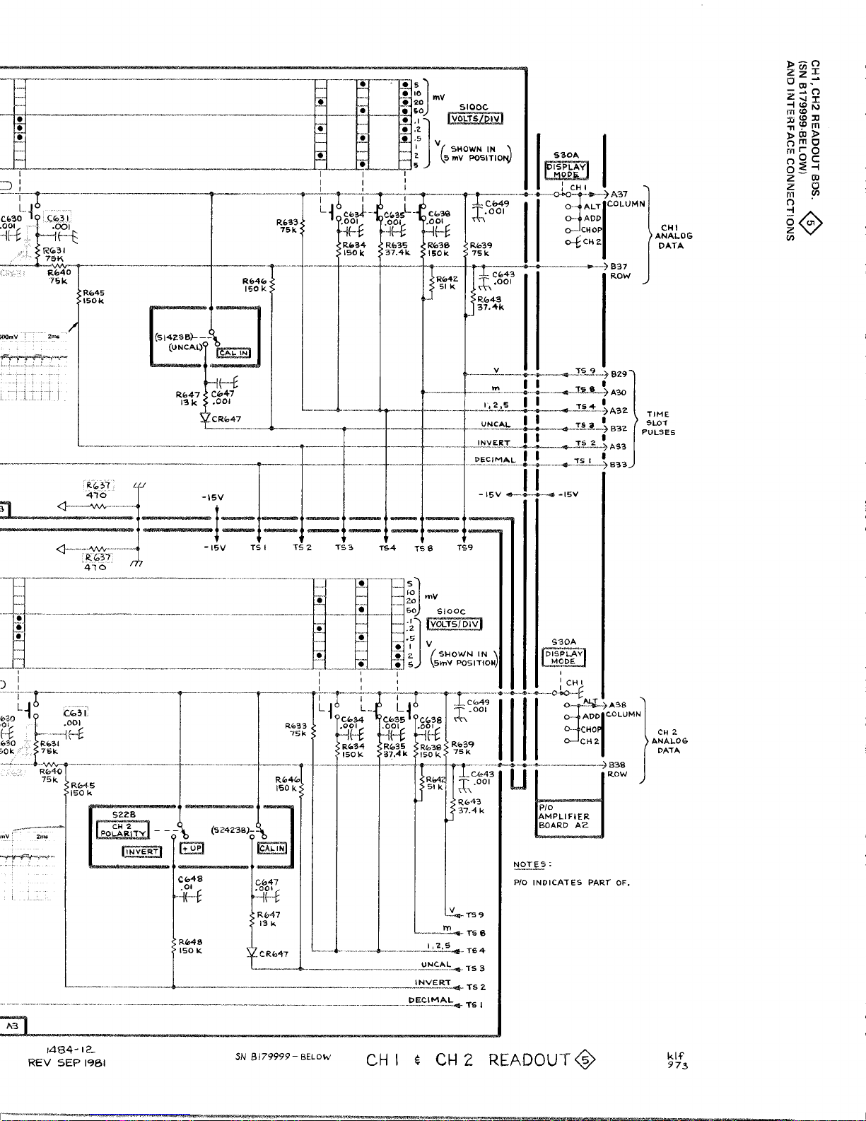
I
mV
SIOOC
V
SHOWN
(
5mV
IN
POSITION
SBOA
0030
.-_.._
.p-p
Cr-
p--
O
CHI
._
1
-G
T
-m--
ALTICOLUMN
ADD
CHOP
CH
2
s
4
"
_-
e
1
A37
ASO
A32
B32
ANALOG
TIME
SLOT
PULSES
CNI
DATA
.,&-..m
649
RG39
75k
001
1 ,
UNCAI
11
I
2u5
.!
,'.
.
.C
19
001,
RGAO
75k
R645
150
k
1484
REVSEP
S30A
DISPLAY
MODE
i
CHI
O--
~-j
A38
COLUMN
C,,-,
AVDI
O--
CHO
NOTES
:
P/O
INDICATES
D
ECIMALam.
-
1
1981
5N
8179999-BELOW
CH
It
CH
.F5
I
2READOUT
PARTOF.
Q
CH
ANALOG
DATA
klf
973
2
Page 77

HFLF
Channel
DC
Balance
81353
l
C1435
Q
1436
H!=
R
1336
Channel
2X
Gain
1317
R
.
I
~2XBAL
1
Channel
8160
1
Channel
2
Balance
DC
R2353
LocationofAdjustments
SN
B159999-below
Channel
2X
Gain
R2317
2
InputCompent,,tion
Channel
C134
2
Page 78

LocationofAdjustn
REVEMAY
1980
Page 79

ion of
Adjustments
SNB16000
0-above
Page 80

PARTS
ORDERING
Replacement
Tektronix, Inc.Field
ChangestoTektronix
accommodate
andtogive
developed
important,
improved
you
the benefitofthe
in
our
when
informationinyour
number,
improved
representative
number
manual
serial
Ifapart
.
Change
.
number,
you
have
part,
your
will
information,ifany,islocatedatthe rear of
SPECIAL
X000
00X
Part
parts
Office
engineering
ordering
order:Part
and
ordered
local
contact
NOTES
Part
first
removed
INFORMATION
are
available
fromorthrough
or representative
instruments
components
as
latest
department.It is
parts, to
number,
modification
has
been
Tektronix, Inc.Field
you
concerning
AND
added
at this serial
after
this serial
your
.
are
they
circuit
sometimes
become
made
available,
improvements
therefore
include
the
instrument
following
type or
numberifapplicable
replaced
withanew
Office or
any
changeinpart
SYMBOLS
number
number
local
or
this
Section
INDENTATION
This
mechanical
relationships.Followingisan
usedinthe
to
1
234
description
Assembly
Attaching
Detail
PartofAssembly
.
Attaching
Parts of
Attaching
Attaching
the itemitmounts,
Indented
items
indentation.'The
attaching
Attaching
specified
parts
parts
.
.
5
and/or
parts
for
parts
Detail
parts
Parts
always
while
are part
separation
mustbe
parts
column
Component
Assembly
for
Detail
Part
for
the
detail
of,
and
symbol
purchased
SYSTEM
listisindentedtoindicate
example
PartsofDetail
appearinthe
.
and%or
and/or
Part
parts
included
---
separately,
of the
indentation
Name
&
Component
Component
Part
same
are
indentedtothe
with,
"---
indicates
Description
indentation as
the next
unless
8--7A26
item
system
right
higher
the
end
otherwise
.
of
FIGURE
Items
in this
numberstothe
"
a
ACTR ACTUATOR
ADPTR
ALIGN
AL
ASSEM
ASSY
ATTEN
AWG
BD
BRKT
BRS BRASS
BRZ
BSHG
CAB
CAP CAPACITOR HDL
CER CERAMIC HEX
CHAS
CKT
COMP
CONN
COV COVER
CPLG COUPLING
CRT
DEG DEGREE
DWR DRAWER
INCH
NUMBER
ADAPTER ELEM
ALIGNMENT
ALUMINUM
ASSEMBLED
ASSEMBLY
ATTENUATOR
AMERICAN
BOARD
BRACKET
BRONZE
BUSHING FXD
CABINET
CHASSIS
CIRCUIT
COMPOSITION
CONNECTOR
CATHODE
AND
section are
illustrations
SIZE
WIRE
GAGE
RAY
TUBE
INDEX
referencedbyfigure
.
ELCTRN
ELEC
ELCTLT
EPL
EQP'T
EXT
FIL
FLEX FLEXIBLE
FLH
FLTR
FR
FSTNR FASTENER
Fr
GSKT GASKET
HEX
HEX
HLCPS
HLEXT
HV
IC
ID
(DENT
IMPLR IMPELLER
NUMBERS
HD
SOC
and
ABBR
ELECTRON
ELECTRICAL
ELECTROLYTIC
ELEMENT
ELECTRICAL
EQUIPMENT
EXTERNAL
FILLISTER
FLAT
FILTER
FRAMEorFRONT
FOOT
FIXED
HANDLE
HEXAGON
HEXAGONAL
HEXAGONAL
HELICAL
HELICAL
HIGH
INTEGRATED
INSIDE
IDENTIFICATION
HEAD
COMPRESSION
EXTENSION
VOLTAGE
DIAMETER
HEAD
index
PARTS
HEAD
SOCKET
CIRCUIT
descriptionbya
canbeutilized
VIATIONS
IN
INLAND
INSUL
INTL
LIST
LPHLDR
MACH
MECH
MTG
NIP
NON
OBD
OD
OVH
-PHBRZ
PL
PLSTC
PN
PNH
PWR
RCPT
RES
RGD
RLF RELIEF
RTNR
SCH SOCKET
SCOPE OSCILLOSCOPE XFMR
SCR
In
Name
Name
identification,
WIRE
ITEM
NAME
the Parts
may
INCH
INCANDESCENT
INSULATOR
INTERNAL
LAMPHOLDER SHLDR SHOULDERED
MACHINE
MECHANICAL
MOUNTING
NIPPLE
NOT
ORDERBYDESCRIPTION
OUTSIDE
OVAL
PHOSPHOR
PLAINorPLATE
PLASTIC
PART
PAN
POWER
RECEPTACLE
RESISTOR
RIGID
RETAINER
SCREW
List,anItem
colon(:).Becauseofspace
sometimes
appearasincomplete.For
theU.S.Federal
where
possible
.
WIRE
WOUND
DIAMETER
HEAD
BRONZE
NUMBER
HEAD
HEAD
Name
is
separated
limitations,
Cataloging
SE
SECT
SEMICOND
SHLO
SKT
SL
SLFLKG SELF-LOCKING
SLVG
SPR
SO
SST
STL
SW
T TUBE
TERM
THD
THK
TNSN
TPG
TRH TRUSS
V
VAR
W/
WSHR
XST
-
R
Handbook
SINGLE
SECTION
SEMICONDUCTOR
SHIELD
SOCKET
SLIDE
SLEEVING
SPRING
SQUARE
STAINLESS
STEEL
SWITCH
TERMINAL
THREAD
THICK
TENSION
TAPPING
VOLTAGE
VARIABLE
WITH
WASHER
TRANSFORMER
TRANSISTOR
from
further
END
HEAD
the
an Item
Item
H6-1
STEEL
REV
C,
AUG
1975
Page 81

Replaceable Mechanical Parts--m-7A26
Mfr.Code
OOOBK
OOOCY
OOOEX
OOOFW
00779
08261
12360
22526
22599
24931
42838
70278
73743
78189
79136
80009
83385
84830
86928
87308
92101
93907
97464
98978
Manufacturer
STAUFFER
NORTHWEST
O'HARA
WESTERN
AMP,
SPECTRA-STRIP
ALBANY
DYNAMICS
BERG
ESNA,
SPECIALITY
NATIONAL
ALLIED
SPARTON
FISCHER
ILLINOIS
SHAKEPROOF
WALDES,
TEKTRONIX,
CENTRAL
LEE
SEASTROM
N.L.INDUSTRIES,
DIV
SCHULZE
BURLINGAME,
TEXTRON
INDUSTRIAL
INTERNATIONAL
METAL
INC
.
PRODUCTS
ELECTRONICS,
DIV.OF
STEEL
SPECIAL
TOOL
KOHINOOR,
SCREW
SPRING
.
MFG,
SUPPLY
SINTERING
CORPORATION
CONNECTOR
RIVET
CORP
INC
COMPANY,
MFG.COMPANY,
INC.CAMCAR
RETAINING
FASTENER
PRODUCT
CORP
AMERACE
AND
AND
.
MFG
WORKS,
DIVISION
.
CO
INC
INGOLD
50
CA
94010
ELECTRONIC
CROSS
SALES,
COMPANY
CO
INC
.
CO.,DIV.OF
INC
.
CORPORATION
CO.,INC
MFG.CO
CONVEYORS,
.CO.
INC
INC
.
.
INC
.,
SOUTHERN
RD
DIV
RINGCO.
.
.
.
.
INC
RESEARCH
INDEX--MFR
INC
.
PNEUMO
.
DIV
.
OF
.
SCREW
CORP
.
CODE
Address
105
7923SWCIRRUS
542BRANNAN
2620
POBOX
7100
145
WOODWARD
YOUK
16150
2620
1-21
17333
446
ST.CHARLES
47-16
POBOX
2530
MAIN
30
701
SONORA
P.O.BOX
600
CORDIER
57
.
135W.
NUMBER
TAYLOR
SE
STEVENS
3608
LAMPSON
EXPRESSWAY
STAGG
ENDRESS
EAST
HEALY
MORGAN
AUSTEL
500
CRESCENT
STREET
18TH
MAGNOLIA
TO
STREET
DRIVE
STREET
JEFFERSON
ST
ROAD
PLACE
AVENUE
1360
AVE
ST
MANUFACTURER
DRIVE
.
AVE
AVENUE
PLACE
ST
.
DR
.
.
BLVD
City
PORTLAND,
BEAVERTON,
SAN
RICHLAND,
HARRISBURG,
GARDEN
SOUTH
NEW
VAN
.
.
GREENWOOD,
WAUPUN,
DETROIT,MI48212
CINCINNATI,OH45206
ELGIN,IL60120
LONG
BEAVERTON,
BROADVIEW,
BROOKLYN,
GLENDALE,
STATESVILLE,
ROCKFORD,
IRVINGTON,NJ
BURBANK,
Zip
State,
97214
OR
OR
WA
99352
PA
GROVE,
IN
WI
53963
CITY,NY11101
OR
IL
60153
NY
11201
CA
91201
NC
IL
61101
07111
CA
91502
97005
CA
46142
97077
FRANCISCO,
NORWALK,CT
CUMBERLAND,
NUYS,CA91409
ISLAND
CA
17105
28677
94107
92642
06586
PA
17070
8-2
REVFEB
1983
Page 82

Fig.&
Index
No
1-1
-2
-3
-4
-5
-6
-7
-8
-9
-10
-11
-12
-13
-14
-15
-16
-17
-18
-19
-20
-21
-22
-23
-24 210-0223-01
-25
-26
-27
-28
-29
-30
-31
-32
-33
. ^
Tektronix
PartNo.
131-0679-00
366-1059-00
366-1077-00
213-0153-00
366-1308-00
213-0153-00
366-1299-00
213-0153-00
366-1163-00
213-0153-00
366-1165-00
213-0153-00
366-0215-02
333-1594-00
333-1594-01
366-1058-45
214-1095-00
105-0076-02
105-0076-04
214-1280-00
348-0235-00
214-1035-00
210-0905-00
358-0216-00
----- -----
211-0030-00
210-0404-00
386-1447-54
213-0192-00
213-0793-00
131-1075-00
----- -----
210-0583-00
672-0051-00
672-0051-01
672-0051-02
672-0051-03
672-3051-04
672-0051-06
672-0051-09
211-0008-00
-----
.,---..
_--_------
129-0299-00
210-0004-00
211-0001-00
210-0053-00
210-1110-00
210-0405-00
131-1030-00
Serial/Model
Eff
8010100
8208880
B010100
8245380
8242000
8242000
8010100
8223842
B010100 B059999
8060000 B079999
8080000 8119999
8120000 8149999
8150000 8179999
8180000 8208879
8208880
No
DscontAm~Qty
8208879
B245379
8223841
.
2
2
2
2
2
2
2
4 .SE-1 -
1
1
1
2
2
1
1
1
1
1
1
1
2
1
1
1
2
4
4
1
4
4
1
2
2
2
2
2
2
2
2
2
2
2 SCREW,MACHINE
-
2
8
8
6
6
6
6
20
^_-12 344`5
CONNECTOR,
PUSH
KNOB
.SETSCREW
KNOB
.SE*rsCREW
KNOB
KNOB:LIGHT
.SETSCREW
KNOB
.SEISCREW
KNOB
PANEL,FRONT
PANEL,F'RONT
KNOB
"""""""(AT-I-ACHING
PIN,SPG,SPL11:0.094ODX0
""""""(END
REI_
RELEASE
SPRING,HLCPS:0.14ODX1.126"L,0
SHLD
SPRING,HLCPS
WASHER,
BUSHING,
SWITCH,
""""""""(ATTACHING
SCREW,MACHINE
NUT,PLAIN,SPLIN
* ... . ..*. . .
SUBPANEL,FRONT
"""""""(ATTACHING
SCR,TPG,THD
SCREW,TPG,''F
""""""(END
CONTACT,ELEC
RES
""""""'
NUT,
TERMINAL,LUG:0.25
""'""""(END
CKT
CKT
CKT
CKT
CKT
CKT
CKT
.. . ... . ... . ...(A-I"IACHING
"""""
CK1
CKT
... . .. . . ... .
.POST,ELEC-MECH
.WASHER,LOCK
.SCREW,MACHINE
.WASHER,LOCK
.WASHER,FLAT:0.092 IDX0.14ODBRS
.NU"r,PLAIN,HEX.:2-56X0
'
."'.'.'..(END
CKT
.CON''
.
_m
_
, .
_-Name
RCPT,
BUTTOWGRAY
:GRAY
:5-40X0
:RED
:5-40X0
:GRAY
SCREW
:5-40X0.125,STL
GRAY
:5-40X0.125,STL
:GRAY
:5-40X0.125,STL
:LEVER
SWITCH
:
:
:GRAY
BAR,LAT'CH
.,VAR:(SEE
PLAIN,HEX:0.25-32
BOARD
BOARD
BOARD
BOARD
BOARD
BOARD
BOARD
-
BOARD
BOARD
BOARD
ATTACHING
:PLUG-IN
BAR,LCH
GSKT',ELEC:4.734
:0 .3ODX0.265
FLAT:0
PLASTIC
SLIDE
:(SEE
.(END
ATTACHING
FOR
:6-32X0
ATTACHING
:GROUNDING,CU
R1465,
.'(ATTACHING
ATTACHING
ASSY
ASSY
ASSY
ASSY
ASSY
ASSY
ASSY
ATTACHING
.'(END
ASSY
ASSY
.(ATTACHING
ATTACHING
ASSY
ASSY,ELEC
.256IDX0.05
:0 .257 IDX0
:2-56X0
:
:
:READOUT/ATTENUATOR
:READOUT/ATTENUATOR
:READOUT/A"ITENUATOR
:READOUT/ATTENUAT'OR
:READOUT/ATT'ENUATOR
:4-40X0.250,PNH,STL,CD
:#4
:2-56X0
:INTL,0
&
BNC,MALE,3
:
.125,STL
.125,STL
PARTS)
.187
PARTS)""""'
UNIT
:PLUG-IN
INCH
S22A,B,S32
PARTS)"'""""'
.25"82
PARTS)""""'
PARTS)"""""'
.50
:6-32X0
.4375,TAPTITE,FIL
PARTS)"""""
R2465
PARTS)"""""'
.312
X0
INCH
DIA,SE,60
PARIS)""""'
:READOUT/ATTENUATOR
:READOUT/ATTENUATOR
PARTS)
PARTS).....""
INCLUDES
:AT1'ENUATOR(SEEA1
PARTS)
:HEX,0
.333
IN'TL,0
.015'1'HK,ST'LCDPL
.25
.092IDX0.175"OD,S
.188
PARTS)"'
INCLUDES
:CAM
SWITCH,BOTTOM
Description
CONTACT
BK
OXD,HEX
BK
OXD,HEX
OXD,HEX
BK
BK
OXD,HEX
BK
OXD,HEX
"""°""
INCH
UNIT
.16"DIA
LONG
L
THK,BRS
.412
INCH
REPL)
DEG,FLH
INCH,PNH
BEHEATTRTD
REPL)
INCH,BRS
DEG
. . ..... . . . .
:
. . ..'. . .. . .
INCH
LONG
INCH,PNH
INCH,BRS
."'
:
LONG
. .
Replaceable
OD
STL
STL
BEN
PL
REPL)
STL
Mechanical
Mfr
Code
e
24931
80009
80009
OOOCY
80009
OOOCY
80009
OOOCY
80009
OOOCY
80009
OOOCY
80009
80009
80009
80009
22599
80009
80009
80009
92101
84830
83385
80009
83385
80009
80009
87308
93907
80009
73743
86928
80009
80009
80009
80009
80009
80009
80009
83385
80009
OOOBK
87308
83385
86928
73743
80009
Parts-7A26
Part
Mfr
,
N
28JR168-1
366-1059-00
366-1077-00
OBD
366-1308-00
OBD
366-1299-00
OBD
366-1163-00
OBD
366-1165-00
OBD
366-0215-02
333-1594-00
333-1594-01
366-1058-45
52-022-094-0187
105-0076-02
105-0076-04
214-1280-00
OBD
LC-026D-4SS
OBD
358-0216-00
OBD
210-0404-00
386-1447-54
OBD
OBD
131-1075-00
2X20317-402
OBD
672-0051-00
672-0051-01
672-0051-02
672-0051-03
672-0051-04
672-0051-06
672-0051-09
OBD
129-0299-00
OBD
OBD
OBD
OBD
12157-50
131-1030-00
Number
F
REVFEB
1983
8"
3
Page 83

Replaceable
Fig
.
&
Index
No
Tektronix
Part
.
Mechanical
No
.
Parts-7A26
Serial/ModelNo.
Eff
Dsco
Mfr
nt
Qty
1
234
5 N
ame&Description
Code
Mfr
Part
Number
-34
-35
-36
-37
-38
-39
-40
-41
-42
-43
-44
-45
-46
-47
-48
-49
-50
-51
-52
-53
-54
-55
-56
-57
-58
-59
131-1031-00
210-0779-00
210-3082-00
136-0252-01
136-0252-01
136-0333-00
337-1406-00
198-3048-00
131-0707-00
352-0169-00
175-0825-00
214-0269-00
441-1097-00
211-0097-00
210-0004-00
131-0963-00
131-0963-00
131-0907-00
211-0292-00
105-0243-00
213-0214-00
263-1018-00
263-1018-01
211-0116-00
211-0292-00
----- ----105-0243-00
213-0214-00
131-0963-00
354-0391-00
354-0390-00
354-0443-00
210-0406-00
401-0081-02
401-0180-00
401-0180-02
401-0180-00
214-1139-00
214-1139-02
214-1139-03
214-1127-00
214-1752-00
105-0397-00
105-0397-01
401-0115-00
401-0178-00
105-0398-00
105-0398-01
384-0880-00
384-0878-01
337-1754-00
213-0120-00
211-0001-00
8010100 8200569
8200570
B010100 8079999
8080000
8130000
8010100 8191199
8191200
8010100 8191199
8010100 8191199
8010100 8079999
8080000
8010100 8149999
8150000
8191200
6191200
8150000
8010100 8059999
6060000
8060000
8010100 8059999
B060000 8079999
8080000 8191199
8191200
8010100 8059999
8060000
8010100 8059999
B060000
8010100 8059999
8060000
8010100 8059999
8060000
8060000
8060000
8010100 8085114
8085115
8227149
8149999
20..CONTACT
20..RIVET,TUBULAR:0.051ODX0.115
20..EYELET,METALLIC:0
.
52
.CONTACT,ELEC:0.178
.
52
.CONTACT,ELEC:0.178
.
4
.SOCKET,PIN
2
.
.SHLD,ELECT'RICAL
2
.
.WIRE
4
...CONNECTOR,TERM
.
.
2
.HLDR,TERM
FT
.
.WIRE,ELECTRICAL
. .
2
.HEAT
2
.CHAS,PL-IN
4
4
4
1
4
4
2
2
2
2
8
8
-
2
2
4
4
2
2
20
2
2
2
2
2
4
4
8
8
2
2
2
2
2
2
2
2
2
6
6
"""""'(ATTACHING
.SCREW,MACHINE
.WASHER,LOCK
""""'(END
.CONTACT,ELEC
.CONTACT,ELEC
.CON
"'"""""'(ATTACHING
SCR,ASSEM
""""'(END
.ACT
""""""'(ATTACHING
SCREW,CAP
""""'(END
SW
SW
"""""'(ATTACHING
SCR,ASSEM
SCR,ASSEM
"'*"""`(END
CAM
.
.ACTUATOR,SWITCH
""'*"""(ATTACHING
.
.SCREW,CAP
.
.CONTACT,ELEC
.
.RING,RET'AINING
.
.RING,RETAINING:0.338IDX0.025"
.
.RING,RETAINING:0.328
.
.NU1',PLAIN,HEX.:4-40X0.188
.
.BEARING,CAM
.
.BEARING,CAM
.
.BEARING,CAM
.
.BEARING,CAM
.
.SPRING,FLAT:0.885X0.156CUBE
.
.SPRING,FLAT
.
.SPRING,FLAT
.
.ROLLER,DETENT:0.125
.
.ROLLER,DETENT
.
.ACTUATOR,CAM
.
.ACTUATOR,CAM
.
.BEARING,CAM
.
.BEARING,CAM
.
.ACTUATOR,CAM
.
.ACTUATOR,CAM
.
.SHAFT,CAM
.
.SHAFT,CAM
.SHIELD,ELEC
'*""""`(ATTACHINGPARTS)'""""""
.SCR,TPG,THD
.SCREW,MACHINE
SET,ELEC
SINK,XSTR
TACT,ELEC
UATOR,SWITCH
CAM
ACTR
CAM
ACTR
SW
ASSY
"'*""(END
ASSY,EL
:CAM
SWITCH,TOP
.047ODX0.133
INCH
TERM
UNIT
WSHR
SCH
WSHR
WSHR
SCH
SW
SW
:ATTENUATOR
INCH
:U/W0.03
:CAM
CONTACTS
:
:22-26
CONN:2WIRE
:2
WIRE
:0 .312
DIAX0
:ATTENUATOR
PARTS)"'""""'
:4-40
X
0
:#4
ATTACHING
:GROUNDING
:GROUNDING
:GROUNDING,CU
ATTACHING
ATTACHING
AS
AS
ATTACHING
INCLUDES
ATTACHING
:GROUNDING
:0
SW
SW
SW
SW
:GREEN
:RED
SW
SW
:REAR
:FRONT
FOR
.312
INTL,0
.015
PARTS)"""'"'
PARTS)"""""'
:4-40X0.29,BRSNIPL
PARTS)""""'
:AC,DC
PARTS)"""""'
:2-56X0
.375"HEXHDSTL
PARTS)'""""""
:
:
PARTS)"""
:4-40
X
0
:4-40
X0.29,BRS
PARTS)""""'
:
:AC,DC
PARTS)"""""'
:2-56X0.375"HEXHDSTL
PARTS)""""'
.395"FREE
FREEIDX0.448
:FRONT
:FRONT&REAR
:W/INSERT
:FRONT&REAR
COLORED
COLORED
DIAX0
:
SW
:DC,GND,AC
SW
:DC,GND,AC
:CENTER
:CENTER
SW
:ATTEN
SW
:ATTEN
:2-32X0
:2-56X0
.25
LONG
LONG
DIA
AWG,BRS&CUBE
BLACK
RIBBON
.75
INCH,PNH
THK,STL
.312
IDX0
INCH,BRS
.125,SST
.250
INCH,PNH
INCH
L,BRASS
PINS
L
BE
ALBALOY
INCH,PNH
NI
.025"
THK,STL
GILD
INCH,PNH
CD
PL
LONG
OD
CLR
STL
STL
S
PL
BRS
STL
80009
42838
80009
00779
00779
00779
80009
GO
PL
80009
22526 47439
80009
80009
98978
80009
83385
OOOBK
OOOEX
OOOEX
80009
78189
80009
70278
80009
80009
83385
78189
80009
70278
OOOEX
97464
79136
97464
73743
80009
80009
80009
80009
80009
80009
80009
80009
80009
80009
80009
80009
80009
80009
80009
80009
80009
80009
83385
87308
131-1031-00
RA-29952715
210-3082-00
1-332095-2
1-332095-2
1-331677-4
337-1406-00
198-3048-00
352-0169-00
175-0825-00
TXD-032-75
441-1097-00
OBD
OBD
OBD
OBD
131-0907-00
OBD
105-0243-00
OBD
263-1018-00
263-1018-01
OBD
OBD
105-0243-00
OBD
OBD
3100-43-CD
5100-37MD
200-37
12161-50
401-0081-02
401-0180-00
401-0180-02
401-0180-00
214-1139-00
214-1139-02
214-1139-03
214-1127-00
214-1752-00
105-0397-00
105-0397-01
401-0115-00
401-0178-00
105-0398-00
105-0398-01
384-0880-00
384-0878-01
337-1754-00
OBD
OBD
8-
4
REV
FEB
1983
Page 84

Fig
Index
No
Replaceable
.
&
Tektronix
.
PartNo.
Serial/Model
Eff
No
Dscont
.
Qty
1
2 3 4 5
Name&Description
Mechanical
Mfr
Code
Mfr
Parts--7-026
Part
Number
-60
-61
-62
-63
-64
-65
-66
-67
-68
-69
-70
-71
-72
-73
-74
-75
-76
-77
-78
-79
-80
-81
-82
-83
-84
-85
-86
-87
-88
-89
-90
-91
-92 2
-93
-94
-95
-96
-97
-98
-99
210-0053-00
210-1008-00
210-1110-00
337-1418-01
337-1418-02
211-0001-00
210-0053-00
210-1008-00
210-1110-00
-------,136-0252-04
136-0350-00
---------361-0515-00
214-1190-02
214-1136-00
351-0180-00
131-0604-00
210-0288-00
211-0105-00
210-0586-00
211-0007-00
337-1716-00
213-0055-00
200-1442-00
211-0007-00
210-0994-00
210-0004-00
407-1172-00
211-0008-00
210-0586-00
384-1194-00
384-1178-00
384-1388-00
376-0039-00
376-0152-00
376-0125-00
376-0124-00
210-0583-00
210-0046-00
129-0080-00
129-0554-00
211-0008-00
-----
----
210-0590-00
210-0012-00
8010100
8191200
8010100 8199799
8199800
8010100
8191200
8010100 8072899
8072900
8150000
8150000
8150000
8150000
8150000
8010100
8191300
8010100 8149999
8150000
8150000
8010100
8020000
8010100
8010100
8010100 8149999
8150000
8191199
8191199
8191299
8019999
8149999
8149999
.WASHER,LOCK
6
.WASHER,FLAT:0.09IDX0.188"
6
.WASHER,FLAT
6
""'"°""(END
2
.SHIEI-D,El..EC
2
.SHIELD,ELEC
"""""'(ATTACHING
6
.SCREW,MACHINE
6
.WASH
ER,LOCK
6
6
2
6
2
4
4
2
2
2
6
2
2
2
2 SCREW,MACHINE
2
2
2
6
6
6
2
4
2
2
2
2
2
2
2
2
2
4
2
2
2 SCREW,MACHINE
1
1
1
ER,FLAT
.WASH
ER,FLAT
.WASH
""""'(END
CKT
BOARD
.
.SOCKET,PIN
.
.SOCKET,PLUG-IN:3PIN,LOWPROFILE
.
.RESISTOR,VAR
.
.SPACER,SWITCH
.CPLG,SHAF'I,RGD:0.125
.
.
.ACTUATOR,SL
.
.SLIDE,GUIDE
.
.CONTACT,ELEC
TERMINAL,LUG:0.125IDX1.125
. . . .. . . .
. . . ..
SCREW,MACHINE
NUT,PL,ASSEM
""""""(END
SHIELD,ELEC
. . ... . ... . ...
SCR,TPG,THD
""""'*"(END
COVER,CHASSIS
. . .. ."... . ..
SCREW,MACHINE
WASHER,FLAT:0.125IDX
WASHER,LOCK
. ... . ... . ...(END
BRACKET,CKT
. ...*..
. . ... .
SCREW,MACHINE
NU'r,PL,ASSEM
. ... . ... . ...(END
EXTENSIONSHAFT:7.22LX0
EXTENSION
EXTENSION
ADP"T,SHAFT,CPLG:0.128
CPLG,SHAFT,
COUPLER,CAM
ARM,SWITCH
RES
.,VAR
. .. . . .. . ... . .
NUT,PLAIN,HEX:0.25-32X0.312
WASHER,LOCK:0.261
. .. . ... . .. .
SPACER,POST:0.875
SPACER,POST:0.975'LW/4-40
.. . . ... . .. . . .
.. . . ... . .. .
SWITCH,WIRED
.. . . ... . .. . . .
NUT,PLAIN,HEX.:0
WASHER,LOCK
.. . ... . ... .
:INTL,0
:0
.092
ATTACHING
:CAM
:CIRCUIT
:2-56X0
:INTL,0
:0
.09
:0
.092
ATTACHING
ASSY
TERM
:(SEE
:PLASTIC
SW
:SWITCH
:CKTBDSW,SPR,CU
.(ATTACHING
:4-40
WA
:4-40X0
ATTACHING
:ATTENUATOR
.(ATTACHING
FOR
:2-32X0
ATTACHING
:ATTENUATOR
. .
(ATTACHING
:4-40X0
:#4
ATTACHING
B0
:BRASS
.(ATTACHING
:4-40X0
WA
ATTACHING
SHAF1':0.123ODX6.1INCH
SHAFT':3.02LX0
RGD:0.075&0
SW
ACTR
:(SEE
R1423,
.(ATTACHING
.(END
ATTACHING
.(ATTACHING
.(END
.(END
:4-4,0X0.250,PNH,STL,CD
ATTACHING
:(SEE
.(ATTACHING
.375X0.438
:INTL,0
ATTACHING
.092IDX0.175"OD,S
ID
SWITCH
.092IDX0
ID
X0
ID
:READOUT(SEE
:U/W0.016-0
R1423A,R2423
:DUAL
:4-40
INTL,0
:4-40
:
:DRIVER
R2423REPL)
ID,IN°I
L,W/440
S30A,B
.375IDX0
OD,BRS
X0.14ODBRS
PARTS)""""'
CASTING
BOARD
PARTS)""""'"'
INCH,PNH
.25
OD,BRS
.188"
X0.14ODBRS
PARTS)""""'
.018
ODTO0.081
DPST
ACTUATOR
INCH
PARTS)"""""'
X
0
.188,100
X
0.25,STL
.188
INCH,PNH
PARTS)""""'
PARTS)
.. . . ... . .. .
.188
INCH,PNH
PARTS)'""""'
PARTS)"""'""'
.188
INCH,PNH
OD,STL
0
.25"
.015
THK,STL
PARTS)
PARTS).. . ... . ... .
.250,PNH,S1-L,CDPL
X0.25,STL
PARTS)
.123ODEPOXY-GL
.078
AND
0.082"DIA
.125
IDAL
PARTS)
. . . .. . ... . .
INCH,BRS
L,0
.018
PARTS)..
THD,NYLON
THD,PLSTC
PARTS)
). ... .
PARTS).. . ... . ..
REPL)
PARTS)
. ... . . .. . .
INCH,STL
.50"ODS
PARTS)
$TL
.175"OD,S
REPL)
A3
DIA
PINS
REPL)
OD,AL
BE
LONG
DEG,FLH
STL
STL
CD
. .. . . ... .
. .. . . .. . .
LONG
OD,SST',PSVT
SHAFT
THK,BRS
. . .. . ..
. . . .
'°
.
. . . .. . ...
STL
PL
83385
12360
86928
80009
80009
87308
83385
12360
86928
22526
80009
80009
80009
80009
80009
80009
80009
ST
PL
83385
83385
83385
80009
93907
80009
83385
86928
OOOBK
80009
83385
83385
80009
80009
80009
80009
80009
80009
80009
73743
78189
80009
80009
83385
73743
78189
OBD
OBD
OBD
337-1418-01
337-1418-02
OBD
OBD
OBD
OBD
75060-007
136-0350-00
361-0515-00
214-1190-02
214-1136-00
351-0180-00
131-0604-00
210-0288-00
OBD
OBD
OBD
337-1716-00
OBD
200-1442-00
OBD
5702-201-20
OBD
407-1172-00
OBD
OBD
384-1194-00
384-1178-00
384-1388-00
376-0039-00
376-0152-00
376-0125-00
376-0124-00
2X20317-402
1214-05-00-0541C
129-0080-00
129-0554-00
OBD
2X28269-402
1220-02-00-0541C
REV
FEB
1983
8-
5
Page 85

ReplaceableMechanical
Fig.&
Index
No
-100
-101
-102
-103
-104
-105
-106
-107
-108
-109
-110
-111
-112
-113
-114
-115
-116
-117
-118
-119
-120
-121
-122
-123
-124
-125
-126
-127
-128
Tektronix
.
PartNo.
----- ----175-0826-00
175-0827-00
175-0828-00
----- -----
211-0008-00
----- ----131-0608-00
136-0252-04
136-0252-07
136-0350-00
214-0579-00
407-0553-00
407-0912-00
386-1402-00
213-0192-00
213-0793-00
361-0326-00
220-0547-01
211-0105-00
105-0075-00
214-1054-00
214-1061-00
426-0736-00
426-0737-00
337-1064-00
198-2150-00
131-0707-00 18
352-0169-09
352-0166-09
175-0825-00
175-0826-00
175-0827-00
175-0828-00
175-0829-00
175-0831-00
175-0832-00
Serial/Mo
Eff
B010100 B072899
B072900
B072900
B010100 B149999
B010100
B223842
Parts--7A26
elNo.
Dscont
B223841
Qty
1
2 3 4 5
-
SWITCH
FT
FT .CABLE,SP,ELEC
FT
1
2
4
162
120
14
1
2
1
1
4
4
1
4
4 SCREW,MACHINE
1
1
1
1
1
2
1
1
2
FT
FT
FT
FT
FT
FT
FT .WIRE,ELECTRICAL
ASSY
.WIRE,ELECTRICAL:3WIRE
.WIRE,ELECTRICAL:5WIRE
CKT
BOARD
""""""'*'(ATTACHING
SCREW,MACHINE
"""""'"(END
CKT
.TERMINAL,PIN:0.365
SOCKET,PIN
SOCKET,PIN
.SOCKET,PLUG-IN:3PIN,LOW
TERM,TEST
.BRACKET,CMPNT
BRACKET,CKT
PANEL,REAR
"""""""(ATTACHING
SCR,TPG,THD
SCREW,TPG,TF
SPACER,
""""""(END
NUT,BLOCK:0.38X0
.
. .
.* .,
'""""""(END
BOLT,LATCH
SPRING,FLAT:0.825X0
SPRING,GROUND
FRSECT,PLUG-IN:TOP
FRSECT,PLUG-IN:BOTTOM
SHIELD
WIRE
.CONNECTOR,TERM
CONN
HLDR,TERM
.WIRE,ELEC'TRICAL:2WIRE
.WIRE,ELEcTRICAL:3WIRE
.CABLE,SP,ELEC
.WIRE,ELECTRICAL:5WIRE
.WIRE,ELEC'TRICAL:6WIRE
.WIRE,ELECTRICAL:8WIRE
ASSY
BOARD
ASSY
POINT
:
SLEEVE:0
.. . . . .
.(ATTACHING
:7A&7B
ELEC
SET,ELEC
BODY,PL,EL:2WIRE
CONN:8WIRE
N
ame&Description
INCLUDES
ATTACHING
TERM
CONN
BD
FOR
:6-32X0.4375,TAP`TITE,FIL
ATTACHING
ATTACHING
:SIDE
:
:
:4,26
:AMPLIFIER(SEE
:4-40X0
:BRASS
:BRASS
:6-32X0
.18IDX0.25
:4-40X0.188,100
:FLAT
:4,26
RIBBON
AWG,STRD
RIBBON
PARTS)"""""'
.250,PNH,STL,CD
PARTS)""""'
INCLUDES
LX0
.025PHBRZ
:U/W0.016-0
:W/O
DIMPLE
:BRSCDPL
ALBALOY
CU-SN-ZN
PARTS)'*""""'
.50
PARTS)""""'
.26X0
.282
PARTS)'*"""""
PARTS)""""'
SER
PL-IN
.322,SST
PLUG-IN
UNITS
:22-26
AWG,BRS&CUBE
WHITE
WHITE
RIBBON
RIBBON
AWG,STRD
RIBBON
RIBBON
RIBBON
:9
WIRE
RIBBON
:
.PVC
A2
.018
PROFILE
INCH,PNH
ODX0
(2)4-40
DEG,FLH
.PVC
JKT,RBN
REPL)
DIA
PL
PL
.10"L
JKT,RBN
GOLD
PINS
STL
Mfr
Code
80009
08261
08261
PL
ST
GOLD
83385
22526 47357
22526
22526
80009
80009
80009
80009
80009
87308
93907
80009
OOOFW
83385
80009
80009
80009
80009
80009
80009
80009
22526 47439
80009
80009
80009
80009
08261
08261
08261
08261
08261
Mfr
Part
Number
175-0826-00
SS04267(1061)OC
SS-0526-710610C
OBD
75060-007
75060-012
136-0350-00
214-0579-00
407-0553-00
407-0912-00
386-1402-00
OBD
OBD
361-0326-00
OBD
OBD
105-0075-00
214-1054-00
214-1061-00
426-0736-00
426-0737-00
337-1064-00
198-2150-00
352-0169-09
352-0166-09
175-0825-00
175-0826-00
SS04267(1061)OC
SS-0526-710610C
SS-0626-710610C
SS-0826-710610C
SS-0926(1061)OC
8-
6
REVFEB
1983
Page 86

V,
~
REVNOV
198
Page 87

A2
EV
NOV
1981
7A26
DUAL
TRACE
AMPLIFIER
Page 88

.
&
Gy
Index
---
No
.PartNo.
-
z
Tektronix
----
oro-z4a*-u1
Soh*!/moJo!
----
ER
No._
"^
D~oot
r
`""
.
1
/'`
^ ,
uumnxL'rocn
Nome
.zmxruocrzom
&
Description
_
WK,
Code
80009
0K,
Part
nro'14o4-oz
Number
--
 Loading...