

Page 1
Keithley Instruments
28775 Aurora Road
Cleveland, Ohio 44139
1-800-935-5595
tek.com/keithley
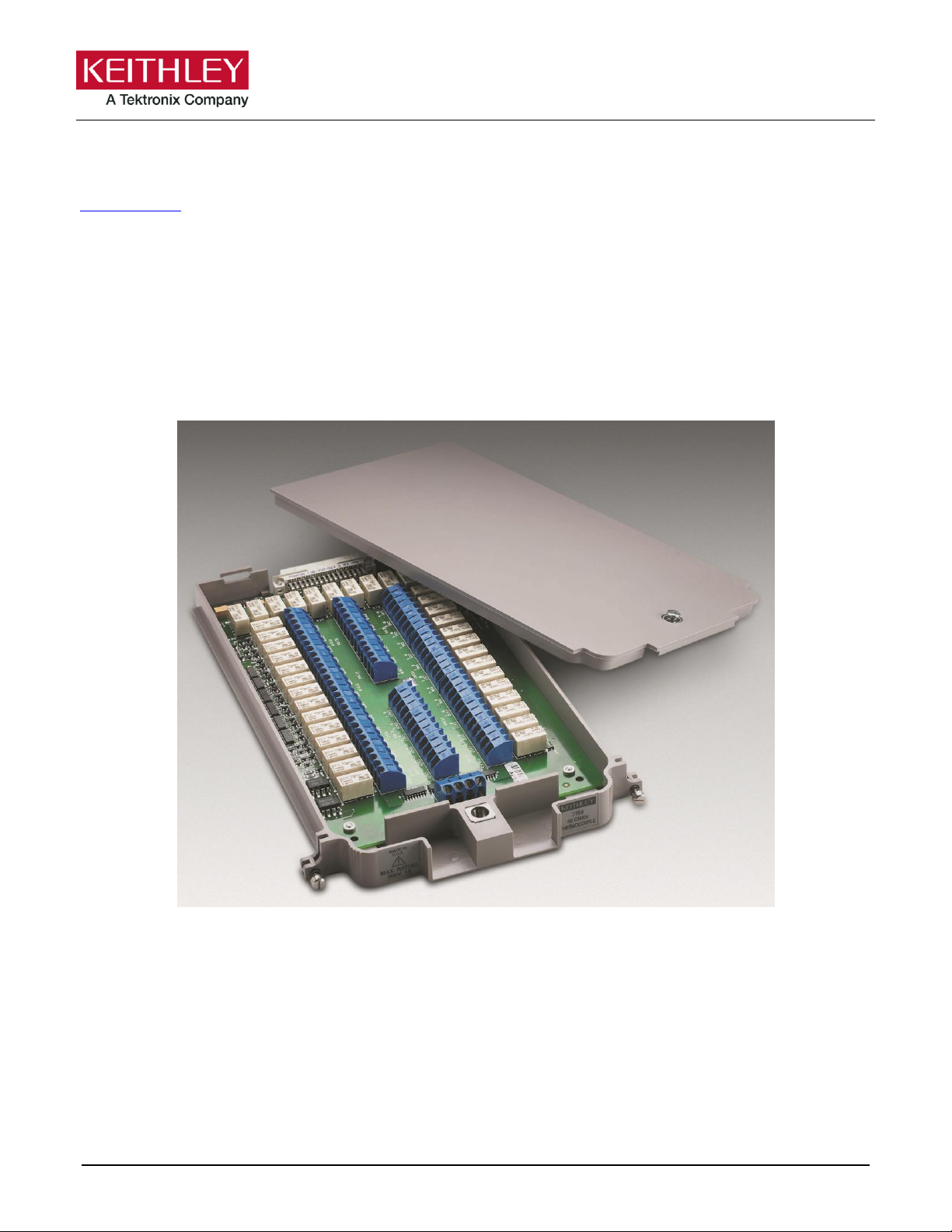
Model 7708 Multiplexer Module
Instructions for use with DAQ6510
077144500 / April 2018 *P077144500* 1
Introduction
The Model 7708 40-Channel Differential Multiplexer Plug-In Module with Automatic CJC offers 40 channels
of 2-pole or 20 channels of 4-pole multiplexer switching that can be configured as two independent banks
of multiplexers. Automatic CJC is provided so that no other accessories are required to make thermocouple
measurements. The 7708 is ideal for RTD, thermistor, and thermocouple temperature applications. It is also
well suited for mixed-signal measurement applications that require multi-point monitoring, such as
environmental stress screening.
Figure 1: Model 7708 40-Channel Differential Multiplexer Module
Item shipped may vary from model pictured here.
Page 2
Model 7708 Multiplexer Module Instructions for use with DAQ6510
2 077144500 / April 2018
The 7708 includes the following features:
▪ DC and AC voltage measurement
▪ Two-wire or four-wire resistance measurements (automatically pairs switches for four-wire
measurements—n + 20)
▪ Temperature applications (RTD, thermistor, thermocouple)
▪ Built-in cold junction reference
▪ Screw terminal connections
The 7708 can be used with the DAQ6510 data acquisition instrument.
If you are using this switching module with the 2700, 2701, or 2750, please see the Model 7708 40Channel Differential Multiplexer with Automatic CJC User's Guide, Keithley Instruments document
number PA-744.
Connections
Connection and wiring procedures in this document are intended for use by qualified
personnel only. Do not perform these procedures unless qualified to do so. Failure to
recognize and observe normal safety precautions could result in personal injury or death.
Do not exceed the maximum specifications for the 7708 module. Refer to the specifications
provided in the data sheet. Failure to recognize and observe normal safety precautions could
result in personal injury or death.
Page 3

Model 7708 Multiplexer Module Instructions for use with DAQ6510
077144500 / April 2018 3
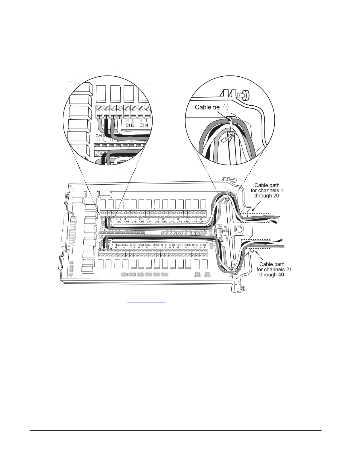
Wiring procedure
Use the following procedure to make connections to the 7708 module. Make all connections using the correct
wire size (up to 20 AWG).
All wiring must be rated for the maximum voltage in the system. For example, if 1000 V is
applied to the front terminals of the instrument, the switching module wiring must be rated
for 1000 V. Failure to recognize and observe normal safety precautions could result in
personal injury or death.
Equipment needed:
▪ Flat-blade screwdriver
▪ Cable ties
To wire the 7708 module:
1. Make sure all power is discharged from the 7708 module.
2. Using a screwdriver, turn the access screw to unlock and open the cover.
Figure 2: Screw terminal access
3. Using a small flat-blade screwdriver, loosen terminal screws and install wires as needed. Channel
designations for the screw terminals are shown in the following figure.
Page 4
Model 7708 Multiplexer Module Instructions for use with DAQ6510
4 077144500 / April 2018
4. Route wire along the cable path and secure with cable ties as shown. The following figure shows
connections to channels 1 and 2.
Figure 3: Wire dressing
5. Record the connections in the Connection log (on page 8).
6. Close the cover.
7. Using a screwdriver, press in the access screw and turn to lock the cover.
Page 5

Model 7708 Multiplexer Module Instructions for use with DAQ6510
077144500 / April 2018 5
Schematic diagram
The simplified schematic diagram of the 7708 is shown in the following figure. The channels are grouped into
two banks of 20 channels (40 channels total). Backplane isolation is provided for each bank. Each bank also
includes separate cold junction reference points.
The first bank contains channels 1 to 20 and the second bank contains channels 21 to 40. Each channel is
wired with separate inputs for HI/LO, providing fully isolated inputs.
Although the 7708 relays are the latching type (relays hold their state even after power has been removed), all
relay states are set to open a few seconds after either a power cycle or a reset command is issued.
Connections to DMM functions are provided through the module backplane connector of the instrument.
When automatically configured for 4-wire measurements (including 4-wire resistance and RTD temperature),
the channels are paired as shown in the following table. Connect 4-wire sense leads using channels 21 to 40.
CH1 and CH21
CH8 and CH28
CH15 and CH35
CH2 and CH22
CH9 and CH29
CH16 and CH36
CH3 and CH23
CH10 and CH30
CH17 and CH37
CH4 and CH24
CH11 and CH31
CH18 and CH38
CH5 and CH25
CH12 and CH32
CH19 and CH39
CH6 and CH26
CH13 and CH33
CH20 and CH40
CH7 and CH27
CH14 and CH34
The 7708 switching module has 40 channels that can calculate ratio and channel average. The ratio calculation
can be done for the DCV function, and the channel average calculation can be done for the DCV and TEMP
(thermocouples only) functions. Paired channels are used for ratio and channel average. Channels are paired
in the same manner as they are for 4-wire measurements.
Page 6

Model 7708 Multiplexer Module Instructions for use with DAQ6510
6 077144500 / April 2018
Figure 4: Model 7708 simplified schematic
Channel 41 (2W/4W Configuration), Channel 42 (Sense Isolation), and Channel 43 (Input Isolation) are
normally automatically configured by the DAQ6510.
Page 7

Model 7708 Multiplexer Module Instructions for use with DAQ6510
077144500 / April 2018 7
Typical connections
The following examples show typical wiring connections for the following types of measurements:
▪ Thermocouple
▪ Two-wire resistance and thermistor
▪ Four-wire resistance and RTD
▪ DC or AC voltage
Thermocouple connections
Figure 5: Thermocouple connections
Two-wire resistance and thermistor connections
Figure 6: Two-wire resistance and thermistor connections
Page 8

Model 7708 Multiplexer Module Instructions for use with DAQ6510
8 077144500 / April 2018
Four-wire resistance and RTD connections
Figure 7: 4-wire resistance and RTD connections
DC or AC voltage connections
Figure 8: Voltage connections - DC or AC
Page 9
Model 7708 Multiplexer Module Instructions for use with DAQ6510
077144500 / April 2018 9
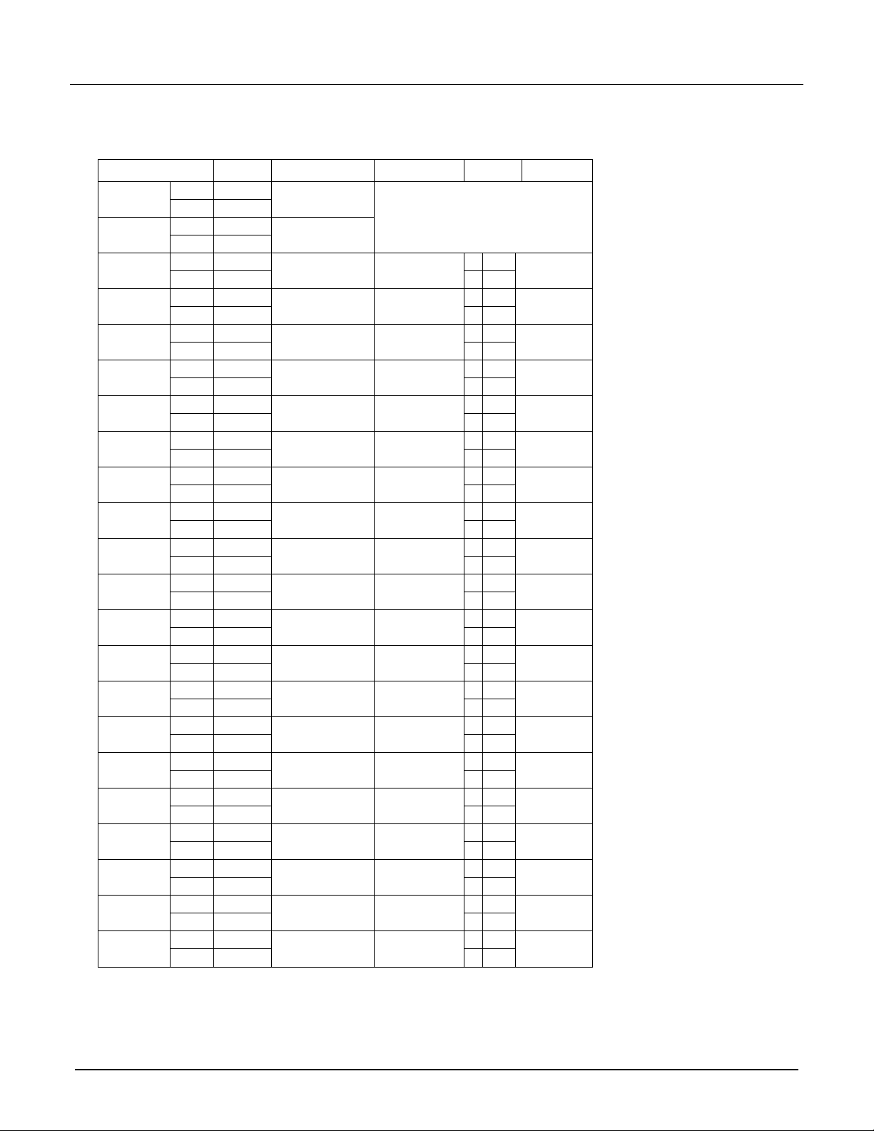
Connection log
You can use the next table to record your connection information.
Channel
Color
Description
Description
Color
Channel
INPUT
H
L
SENSE
H
L
CH1
H
H
CH21
L
L
CH2
H
H
CH22
L
L
CH3
H
H
CH23
L
L
CH4
H
H
CH24
L
L
CH5
H
H
CH25
L
L
CH6
H
H
CH26
L
L
CH7
H
H
CH27
L
L
CH8
H
H
CH28
L
L
CH9
H
H
CH29
L
L
CH10
H
H
CH30
L
L
CH11
H
H
CH31
L
L
CH12
H
H
CH32
L
L
CH13
H
H
CH33
L
L
CH14
H
H
CH34
L
L
CH15
H
H
CH35
L
L
CH16
H
H
CH36
L
L
CH17
H
H
CH37
L
L
CH18
H
H
CH38
L
L
CH19
H
H
CH39
L
L
CH20
H
H
CH40
L
L
Page 10

Model 7708 Multiplexer Module Instructions for use with DAQ6510
10 077144500 / April 2018
Installation
Before operating an instrument with an accessory switching module, verify that the switching
module is properly installed and the mounting screws are tightly fastened. If the mounting
screws are not properly connected, an electrical shock hazard may be present.
To use the switching operations, a switching module must be installed in the DAQ6510.
If you are installing two switching modules, it is easier to install one switching module into Slot 2 first, then
install the second switching module into Slot 1.
If you have a Keithley Instruments Model 2700, 2701, or 2750 instrument, you can use your existing
switching module in the DAQ6510. Follow the instructions in your original equipment documentation
to remove the module from the instrument, then use the following instructions to install it in the
DAQ6510. You do not need to remove wiring to the module.
For inexperienced users, it is recommended that you do not connect a device under test (DUT) and
external circuitry to the switching module. This allows you to exercise close and open operations
without the dangers associated with live test circuits. You can also set up pseudocards to experiment
with switching. Refer to Pseudocards in the Model DAQ6510 Reference Manual for information on
setting up pseudocards.
To prevent electric shock that could result in injury or death, never handle a switching
module that has power applied to it. Before installing or removing a switching module, make
sure the DAQ6510 is turned off and disconnected from line power. If the switching module is
connected to a DUT, make sure power is removed from all external circuitry.
If a card slot is unused, you must install slot covers to prevent personal contact with high
voltage circuits. Failure to install slot covers could result in personal exposure to hazardous
voltages, which could cause personal injury or death if contacted.
Page 11

Model 7708 Multiplexer Module Instructions for use with DAQ6510
077144500 / April 2018 11
Before installing or removing a switching module, make sure the DAQ6510 power is turned
off and disconnected from line power. Failure to comply may result in incorrect operation and
loss of data in the memory.
Required equipment:
▪ Medium flat-blade screwdriver
▪ Medium Phillips screwdriver
To install switching module into the DAQ6510:
1. Turn off the DAQ6510.
2. Disconnect the power cord from the power source.
3. Disconnect the power cord and any other cables that are connected to the rear panel.
4. Position the DAQ6510 so you are facing the rear panel.
5. Use the screwdriver to remove the slot cover screws and the cover plate. Retain the plate and screws for
future use.
6. With the top cover of the switching module facing up, slide the switching module into the slot.
7. Press the switching module in firmly to make sure the switching module connector is connected to the
DAQ6510 connector.
8. Use the screwdriver to tighten the two mounting screws to secure the switching module to the mainframe.
Do not overtighten.
9. Reconnect the power cord and any other cables.
Remove a switching module
Before you remove a switching module, or begin any testing, make sure that all of the relays are
open. Since some relays may be latched closed, you must open all of the relays before removing the
switching module to make connections. Additionally, if you drop your switching module, it is possible
for some relays to latch closed.
To open all channels select Menu > Control > Open. If there are no channels closed, the Open button is not
selectable.If any channel is closed, then the Open button is active and selecting it will open all channels.
To prevent electric shock that could result in injury or death, never handle a switching
module that has power applied to it. Before installing or removing a switching module, make
sure the DAQ6510 is turned off and disconnected from line power. If the switching module is
connected to a DUT, make sure power is removed from all external circuitry.
If a card slot is unused, you must install slot covers to prevent personal contact with high
voltage circuits. Failure to install slot covers could result in personal exposure to hazardous
voltages, which could cause personal injury or death if contacted.
Page 12

Model 7708 Multiplexer Module Instructions for use with DAQ6510
12 077144500 / April 2018
Before installing or removing a switching module, make sure the DAQ6510 power is turned
off and disconnected from line power. Failure to comply may result in incorrect operation and
loss of data in the memory.
Required equipment:
▪ Medium flat-blade screwdriver
▪ Medium Phillips screwdriver
To remove switching module from the DAQ6510:
1. Turn off the DAQ6510.
2. Disconnect the power cord from the power source.
3. Disconnect the power cord and any other cables that are connected to the rear panel.
4. Position the DAQ6510 so you are facing the rear panel.
5. Use the screwdriver to loosen the mounting screws that secure the switching module to the mainframe.
6. Carefully remove the switching module.
7. Install a slot plate or switching module in the empty slot.
8. Reconnect the power cord and any other cables.
Operation
This switching module does not support current measurements. If the instrument has the TERMINALS switch
set to REAR and you are working with the slot that contains this switching module, the AC , DC , and digitize
current functions are not available. You can measure current using the front panel or using another slot that
contains a switching module that supports the AC , DC , and digitize current measurements.
If you use remote commands to attempt to measure current when configuring a channel, an error is returned.
Performance verification
The performance of the module is tested by verifying the accuracy of measurements made through the module.
If verification limits are met through the front-panel terminals of the DAQ6510, they should also be met through
the module.
Do not attempt to perform this procedure unless qualified to do so. Failure to recognize and
observe normal safety precautions could result in personal injury or death.
Measurement accuracy through the module should only be verified after instrument accuracy has
been verified through the front-panel terminals of the DAQ6510. Refer to the DAQ6510 Calibration
and Adjustment manual (documentation number DAQ6510-905-01) for verification information.
Page 13

Model 7708 Multiplexer Module Instructions for use with DAQ6510
077144500 / April 2018 13
This verification procedure requires that the DAQ6510 be within its calibration interval.
Module verification test procedures include:
▪ DC volts
▪ AC volts
▪ Resistance
▪ Temperature
▪ Frequency
▪ Ratio and average
Make sure that you perform the verification tests using the following conditions:
▪ Under the proper environmental conditions
▪ After the specified warm-up period
▪ With connections made to the correct input terminals
▪ Using the correct line voltage
▪ With the TERMINALS switch in the REAR position
▪ With the proper calibration equipment and the reading limits provided with the verification procedures. See
Calculating resistance reading limits (on page 14) for more information.
Environmental conditions
Conduct your performance verification procedures in a test environment that has:
▪ An ambient temperature of 18 °C to 28 °C.
▪ A relative humidity of less than 80% unless otherwise noted.
Warm-up period
Allow the DAQ6510 to warm up for at least one hour before verifying the module.
If the instrument has been subjected to temperature extremes (those outside the ranges stated above), allow
additional time for the internal temperature of the instrument to stabilize. Typically, allow one extra hour to
stabilize an instrument that is 10 °C outside the specified temperature range.
Allow the test equipment to warm up for the minimum time specified by the manufacturer.
Example reading limit calculation
The following is an example of how reading limits have been calculated. Assume you are testing the 10 VDC
range using a 10 V input value. Using the DAQ6510 one-year accuracy specification for 10 VDC of ± (25 ppm
of reading + 5 ppm of range), the calculated limits are:
Reading limits = 10 V ± [(10 V 25 ppm) + (10 V 5 ppm)]
Reading limits = 10 V ± (0.00025 + 0.00005)
Reading limits = 10 V ± 0.00030 V
Reading limits = 9.99970 V to 10.00030 V
Page 14

Model 7708 Multiplexer Module Instructions for use with DAQ6510
14 077144500 / April 2018
Calculating resistance reading limits
Resistance reading limits must be recalculated based on the actual calibration resistance values supplied by
the equipment manufacturer. Calculations are performed in the same manner as shown in the previous
example, except that you should use the actual calibration resistance values instead of the nominal values
when performing your calculations.
For example, assume that you are testing the 10 kΩ range using an actual 10.03 kΩ calibration resistance
value. Using DAQ6510 one-year 10 kΩ range accuracy of ± (75 ppm of reading + 6 ppm of range), the
calculated reading limits are:
Reading limits = 10.03 kΩ ± [(10.03 kΩ 75 ppm) + (10 kΩ 6 ppm)]
Reading limits = 10.02929 kΩ to 10.03081 kΩ
Recommended test equipment
The table below summarizes recommended verification equipment. You can use alternate equipment if that
equipment has specifications that meet or exceed those listed below. Be aware that calibrator uncertainty adds
to the uncertainty of each measurement.
Fluke 5700A Calibrator:
DC voltage
AC voltage (1 kHz, 50 kHz)
Resistance
100 mV: ±14 ppm
100 mV: ±200 ppm
100 Ω: ±17 ppm
1.0 V: ±7 ppm
1.0 V: ±82 ppm
1 kΩ: ±12 ppm
10 V: ±5 ppm
10 V: ±82 ppm
10 kΩ: ±11 ppm
100 V: ±7 ppm
100 V: ±90 ppm
100 kΩ: ±13 ppm
1000 V: ±9 ppm
700 V: ±85 ppm
1 MΩ: ±18 ppm
10 MΩ: ±37 ppm
100 MΩ: ±120 ppm
Fluke 5725A Amplifier
AC Voltage, 50 kHz: 700 V, ±375 ppm
The Fluke 5725A amplifier is necessary only if you need to verify the 750 VAC range at 50 kHz.
Verification at 220 V and 50 kHz using the 5700A calibrator is adequate for most applications.
Keithley 3930A or 3940 Frequency Synthesizer
1 V
RMS
, 10 V
RMS
, 1 kHz, ±5 ppm, steady state and burst modulation
General Radio 1433-T Precision Decade Resistance Box
10 Ω to 400 Ω, ±0.02%
Miscellaneous equipment
Double banana plug to double banana plug shielded cables (two)
BNC to double banana plug shielded cable
Page 15

Model 7708 Multiplexer Module Instructions for use with DAQ6510
077144500 / April 2018 15
Performance verification procedures
The following procedures describe how to check one channel (CH1) or one channel pair (CH1 and
CH11) of the module. To check other channels or channel pairs, modify the procedures by
connecting the verification equipment to the appropriate channel or channel pair.
When performing the verification procedures:
▪ Make sure that the equipment is properly warmed up and connected to the correct input terminals.
▪ Make sure that the TERMINALS switch is set to REAR.
▪ Do not use autoranging for any verification tests. Autorange hysteresis may cause the DAQ6510 to be on
an incorrect range. For each test signal, you must manually set the correct range for the DAQ6510.
▪ Make sure the calibrator output is enabled before you verify each measurement.
▪ Always let the source signal settle before taking a reading.
The verification limits stated in this section have been calculated using only the DAQ6510 one-year accuracy
specifications, and they do not include test equipment uncertainty. If a particular measurement falls slightly
outside the allowable range, recalculate new limits based on both DAQ6510 specifications and pertinent
calibration equipment specifications.
Do not attempt to perform this procedure unless qualified to do so. Failure to recognize and
observe normal safety precautions could result in personal injury or death.
The maximum common-mode voltage (the voltage between any module terminal and chassis
ground) is 300 VDC or 300 V
RMS
. Exceeding this value may cause a breakdown in insulation,
creating a shock hazard.
Page 16

Model 7708 Multiplexer Module Instructions for use with DAQ6510
16 077144500 / April 2018
Verifying DC voltage
To check DC voltage accuracy, apply accurate voltages from the DC voltage calibrator to the input terminals of
the module and verify that the displayed readings fall within specified limits.
Do not exceed 300 VDC between plug-in module INPUT H and L terminals or between any
adjacent channels. Failure to observe this precaution can cause instrument damage.
To verify DC voltage accuracy:
1. Connect the CH1 H and L INPUT terminals to the DC voltage calibrator as shown in the next figure.
Use shielded, low-thermal connections when testing the 100 mV and 1 V ranges to avoid errors
caused by noise or thermal effects. Connect the shield to the output LO terminal of the calibrator.
2. Install the module in Slot 1 of the DAQ6510.
3. Turn on the power.
4. Allow the instrument to warm up for one hour.
5. Make sure that the front-panel TERMINALS switch is set to REAR.
6. On the front panel of the instrument, select the FUNCTION key and then select DC Voltage.
7. On the Home screen, swipe to the CHANNEL swipe screen.
8. Close channel 101.
9. Set the range to 100 mV.
10. Set the calibrator output to 0.00000 mV DC.
11. Allow the reading to settle.
12. Swipe to the Settings screen.
13. Enable Rel.
14. For the calibrator, source positive, negative, and full-scale voltages, see the ranges listed in the table
below. For each voltage setting, make sure that the reading is within stated limits.
15. Return to the CHANNEL swipe screen and open Channel 1.
Page 17

Model 7708 Multiplexer Module Instructions for use with DAQ6510
077144500 / April 2018 17
Range
Applied DC voltage
Reading limits (1 year, 18 °C to 28 °C)
100 mV
100.0000 mV
99.9935 to 100.0065 mV
1 V
1.000000 V
0.999969 to 1.000031 V
10 V
10.00000 V
9.99970 to 10.00030 V
100 V
100.0000 V
99.9955 to 100.0045 V
1000 V
300.000 V
299.983 V to 300.017 V
Verifying AC voltage
To check AC voltage accuracy, apply accurate AC voltages at specific frequencies from the AC voltage
calibrator to the module inputs. Verify that the displayed readings fall within specified ranges.
Do not exceed 300 V
RMS
between the INPUT H and L terminals or between adjacent channels,
or 8 107 V•Hz input. Failure to observe this precaution may result in instrument damage.
To verify AC voltage accuracy:
1. Connect the CH1 H and L INPUT terminals of the module to the AC voltage calibrator, as shown in the next
figure.
Page 18

Model 7708 Multiplexer Module Instructions for use with DAQ6510
18 077144500 / April 2018
2. Install the module in Slot 1 of the DAQ6510.
3. Turn on the power.
4. Allow the instrument to warm up for one hour.
5. Make sure that the front-panel TERMINALS switch is set to REAR.
6. On the front panel of the instrument, select the FUNCTION key and then select AC Voltage.
7. On the Home screen, swipe to the CHANNEL swipe screen.
8. Close channel 101.
9. Set the range to 100 mV.
10. Swipe to the Settings screen.
11. Disable Rel.
12. Source 1 kHz and 50 kHz AC voltages for each of the ranges summarized in the table below. Make sure
that the respective DAQ6510 readings are within stated limits.
13. Return to the CHANNEL swipe screen and open Channel 1.
ACV range
Applied AC voltage
1 kHz reading limits
(1 year, 18 °C to 28 °C)
50 kHz reading limits
(1 year, 18 °C to 28 °C)
100 mV
100.0000 mV
99.910 to 100.090 mV
99.830 to 100.170 mV
1 V
1.000000 V
0.99910 to 1.00090 V
0.99830 to 1.00170 V
10 V
10.00000 V
9.9910 to 10.0090 V
9.98300 to 10.0170 V
100 V
100.0000 V
99.910 to 100.090 V
99.830 to 100.170 V
750 V
300.000 V*
299.60 to 300.40 V
299.27 to 300.73 V
* If the 5725A amplifier is not available, change the 300 V @ 50 kHz step to 220 V @ 50 kHz. Reading limits
for 220 V @ 50 kHz = 219.36 V to 220.64 V.
Page 19

Model 7708 Multiplexer Module Instructions for use with DAQ6510
077144500 / April 2018 19
Verifying resistance
Check resistance by connecting accurate resistance values to the module and verifying that its resistance
readings are within the specified limits.
Do not apply more than 300 VDC between the module INPUT or SENSE H and L terminal
or between any adjacent channels. Failure to observe this precaution can cause
instrument damage.
To verify resistance accuracy:
1. Using shielded Teflon or equivalent cables in a 4-wire configuration, connect the 7700 CH1 H and L INPUT
terminals and CH11 H and L SENSE terminals to the calibrator as shown in the next figure.
2. Install the module in Slot 1 of the DAQ6510.
3. Turn on the power.
4. Allow the instrument to warm up for one hour.
5. Make sure that the front-panel TERMINALS switch is set to REAR.
6. Set the calibrator for 4-wire resistance with external sense on.
7. On the front panel of the instrument, select the FUNCTION key and then select 4W Resistance.
8. On the Home screen, swipe to the CHANNEL swipe screen.
9. Set the range to 100 Ω range.
10. Swipe to the Settings screen.
11. Enable the Filter.
12. For the 100 Ω range, select the MENU key, select Channel Settings, and set Offset Compensation to On.
13. Recalculate reading limits based on actual calibrator resistance values.
14. Source the nominal full-scale resistance values for the 100 Ω to10 MΩ ranges listed in the table below.
Verify that the readings are within calculated limits.
Page 20

Model 7708 Multiplexer Module Instructions for use with DAQ6510
20 077144500 / April 2018
Ω Range
Nominal
resistance
Nominal reading limits
(1 year, 18°C to 28°C)
Recalculated limits**
1 Ω*
1 Ω
0.999715 mΩ to
1.000285 Ω
__________ to __________ Ω
10 Ω
10 Ω
9.99895 mΩ to 10.00105 Ω
__________ to __________ Ω
100 Ω*
100 Ω
99.9895 Ω to 100.0105 Ω
__________ to __________ Ω
1 kΩ
1 kΩ
0.999929 Ω to 1.000081 kΩ
__________ to __________ kΩ
10 kΩ
10 kΩ
9.99929 Ω to 10.00081 kΩ
__________ to __________ kΩ
100 kΩ
100 kΩ
99.9905 Ω to 100.0095 kΩ
__________ to __________ kΩ
1 MΩ
1 MΩ
0.999894 Ω to
1.000106 MΩ
__________ to __________ MΩ
10 MΩ
10 MΩ
9.99590 Ω to 10.00410 MΩ
__________ to __________ MΩ
100 MΩ
100 MΩ
99.7970 Ω to 100.2030 MΩ
__________ to __________ MΩ
* Enable offset compensation for the 100 Ω range.
** Calculate limits based on actual calibration resistance values and DAQ6510 one-year
resistance accuracy specifications. See Calculating resistance reading limits (on page 14) for
more information.
1. Connect the CH1 and CH11 terminals of the module to the calibrator as shown in the next figure.
2. Disable external sense on the calibrator.
3. Set the range of the DAQ6510 to 100 MΩ range.
4. Source a nominal 100 MΩ resistance value. Verify that the reading is within calculated limits for the
100 MΩ range.
5. Return to the CHANNEL swipe screen and open Channel 1.
Page 21

Model 7708 Multiplexer Module Instructions for use with DAQ6510
077144500 / April 2018 21
Verifying temperature
Thermocouple, thermistor, and RTD temperature readings are derived from DC volts and resistance
measurements, respectively. For that reason, it is not necessary to independently verify the accuracy of
temperature measurements. If the DC volts and resistance functions meet or exceed specifications,
temperature function accuracy is automatically verified.
You can verify temperature accuracy using the following procedures.
Thermocouple temperature
This setup and reading limits table below does not include errors from ice point, thermocouple wire, and
connections. HI and LO connections from the calibrator and 7700 must be electrically isolated from each other.
To verify the thermocouple temperature:
1. Connect the DC voltage calibrator output terminals and ice point reference to the CH1 H and L INPUT
terminals of the module using low-thermal shielded connections, as shown in the next figure.
Page 22

Model 7708 Multiplexer Module Instructions for use with DAQ6510
22 077144500 / April 2018
2. Install the module in Slot 1 of the DAQ6510.
3. Turn on the power.
4. Allow the instrument to warm up for one hour.
5. Make sure that the front-panel TERMINALS switch is set to REAR.
6. On the front panel of the instrument, select the FUNCTION key and then select Temperature.
7. On the Home screen, swipe to the CHANNEL swipe screen.
8. Close channel 101.
9. Set the channel to temperature.
10. Configure the channel for °C units, thermocouple, and internal reference junction as follows:
a. Press the MENU key.
b. Select Channel Settings.
c. Set the Transducer to TC.
d. Set the Thermocouple to K or J.
e. Set the Unit to Celsius.
f. Set the Reference Junction to Internal.
11. Source each of the voltages in the table below based on the type of thermocouple used. Verify that the
temperature readings are within limits.
12. Return to the CHANNEL swipe screen and open Channel 1.
Based on the type of thermocouple used, verify your data against the specifications in the following table.
Thermocouple type
Applied DC voltage*
Reading limits (1 year, 18 °C to 28 °C)
J
-7.659 mV
-192.33 °C to -187.67 °C
0 mV
-1.0 °C to +1.0 °C
42.280 mV
749.0 °C to 751.0 °C
K
-5.730 mV
-192.33 °C to -187.67 °C
0 mV
-1.0 °C to +1.0 °C
54.138 mV
1349.0 °C to 1351.0 °C
*Voltages shown are based on the ITS-90 standard.
Page 23

Model 7708 Multiplexer Module Instructions for use with DAQ6510
077144500 / April 2018 23
RTD temperature
To verify the RTD temperature:
1. Connect the precision decade resistance box to the CH1 and CH11 H and L terminals of the module using
four-wire connections. Refer to the first figure in Verifying resistance for connections.
2. Install the module in Slot 1 of the DAQ6510.
3. Turn on the power.
4. Allow the instrument to warm up for one hour.
5. Make sure that the front-panel TERMINALS switch is set to REAR.
6. On the front panel of the instrument, select the FUNCTION key and then select Temperature.
7. On the Home screen, swipe to the CHANNEL swipe screen.
8. Close channel 101.
9. Set the channel to Temperature.
10. Configure the channel for °C units and RTD temperature sensor as follows:
a. Press the MENU key.
b. Select Channel Settings.
c. Set Transducer to 4-Wire RTD.
d. Set 4-Wire RTD to PT385.
11. Source each of the voltages in the table below to verify that the temperature readings are within limits.
Make sure to select the appropriate thermocouple type for each group of readings.
12. Set the decade resistance box to each of the values shown in the table below. Verify that the temperature
readings are within the required limits.
13. Return to the CHANNEL swipe screen, and open Channel 1.
Applied resistance*
Reading limits (1 year, 18 °C to 28 °C)
22.80 Ω
-190.06 °C to -189.94 °C
100.00 Ω
-0.06 °C to +0.06 °C
313.59 Ω
599.94 °C to 600.06 °C
*Based on = 0.00385
Page 24

Model 7708 Multiplexer Module Instructions for use with DAQ6510
24 077144500 / April 2018
Verifying frequency
To verify the module frequency:
1. Connect the function generator to the CH1 H and L INPUT terminals of the module. Refer to the next figure
for more information.
2. Install the module in Slot 1 of the DAQ6510.
3. Turn on the power.
4. Allow the instrument to warm up for one hour.
5. Make sure that the front-panel TERMINALS switch is set to REAR.
6. Set the function generator to output a 1 kHz 1 V
RMS
sine wave.
7. On the front panel of the instrument, select the FUNCTION key and then select Frequency.
8. On the Home screen, swipe to the CHANNEL swipe screen.
9. Close channel 101.
10. Verify that the DAQ6510 frequency reading is between 0.9999 kHz and 1.0001 kHz.
Page 25

Model 7708 Multiplexer Module Instructions for use with DAQ6510
077144500 / April 2018 25
Verifying ratio and average
Follow the procedure below to verify ratio and average.
Do not exceed 300 VDC between plug-in module INPUT H and L terminals or between any
adjacent channels. Failure to observe this precaution can cause instrument damage.
Use shielded cables to minimize noise.
To verify ratio and average:
1. Connect the CH1 H and L INPUT terminals to the DC voltage calibrator as shown in the next figure.
2. Install the module in Slot 1 of the DAQ6510.
3. Turn on the power.
4. Allow the instrument to warm up for one hour.
5. Make sure that the front-panel TERMINALS switch is set to REAR.
6. On the front panel of the instrument, select FUNCTION and then select DCV Ratio.
7. On the Home screen, swipe to the CHANNEL swipe screen.
8. Close channel 101.
9. Set the range to 1 V.
10. Set the calibrator output to 1.00000 VDC.
11. Allow the reading to settle.
12. Verify that the ratio reading is between 0.9999926 and 1.000074.
13. Return to the CHANNEL swipe screen and open Channel 1.
Page 26

Model 7708 Multiplexer Module Instructions for use with DAQ6510
26 077144500 / April 2018
Range
Applied DC voltage
Reading limits (1 year, 18 °C to 28 °C)
100 mV
100.0000 mV
99.9935 to 100.0065 mV
1 V
1.000000 V
0.999969 to 1.000031 V
10 V
10.00000 V
9.99970 to 10.00030 V
100 V
100.0000 V
99.9955 to 100.0045 V
1000 V
300.000 V
299.983 V to 300.017 V
Calibration
The following procedure calibrates the temperature sensors on the modules.
Do not attempt to perform this procedure unless qualified to do so. Failure to recognize and
observe normal safety precautions could result in personal injury or death.
Recommended test equipment
To calibrate the module, you need the following equipment.
▪ Digital thermometer: 18 °C to 28 °C ±0.1 °C
▪ Keithley 7797 Calibration/Extender Board
Extender board connections
The extender board is installed in the DAQ6510. The module is connected to the extender board externally to
prevent heating of the module during calibration.
To make extender board connections:
1. Remove power from the DAQ6510.
2. Install the extender board into Slot 1 of the instrument.
3. Plug the module into the P1000 connector on the rear of the 7797 Calibration/Extender Board.
Page 27

Model 7708 Multiplexer Module Instructions for use with DAQ6510
077144500 / April 2018 27
Calibration procedure
Before calibrating the temperature on the module, make sure that power has been removed from the
module for at least two hours to allow module circuitry to cool down. After turning on the power
during the calibration procedure, complete the procedure as quickly as possible to minimize module
heating that could affect calibration accuracy. Initially allow the DAQ6510 to warm up for at least one
hour with the 7797 calibration card installed. If you are calibrating multiple modules sequentially, then
power off the DAQ6510, quickly unplug the previously calibrated module, and plug in the next one.
You must use remote commands to run calibration. Refer to the DAQ6510 reference manual (document
number DAQ6510-901-01) for information on setting up remote communications.
To set up calibration:
1. Turn on the DAQ6510 power.
2. To make sure that the instrument is using the SCPI command set, send:
*LANG SCPI
3. Turn power off, and turn power back on.
4. On the front panel, verify that TERMINALS is set to REAR.
To calibrate temperature:
1. Accurately measure and record the cold temperature of the module surface at the center of the module with
the digital thermometer.
2. Unlock calibration by sending:
:CALibration:PROTected:CODE "KI006510"
3. Calibrate temperature on the module with the following command, where <temp> is the cold calibration
temperature measured in step 1:
:CALibration:PROTected:CARD1:STEP0 <temp>
4. Send the following commands to save and lock out calibration:
:CALibration:PROTected:CARD1:SAVE
:CALibration:PROTected:CARD1:LOCK
Errors that can occur during calibration
If calibration errors occur, they are reported in the event log. You can review the event log from the front panel
of the instrument, by using the SCPI :SYSTem:EVENtlog:NEXT? command, or by using the TSP
eventlog.next() command.
The error that can occur on this module is "5527, Temperature Cold Cal error." If this error occurs, contact
Keithley Instruments. Refer to Factory service (on page 27).
Factory service
To return the switching module to Keithley Instruments for repair:
▪ Call the Repair Department at 1-800-833-9200 or send an email to RMAREQUEST@tektronix.com for a
Return Material Authorization (RMA) number.
▪ Carefully pack the instrument in the original packing carton.
▪ Write ATTENTION REPAIR DEPARTMENT and the RMA number on the shipping label.
Page 28

28 077144500 / April 2018
Safety precautions
The following safety precautions should be observed before using this product and any associated instrumentation. Although
some instruments and accessories would normally be used with nonhazardous voltages, there are situations where hazardous
conditions may be present.
This product is intended for use by personnel who recognize shock hazards and are familiar with the safety precautions required
to avoid possible injury. Read and follow all installation, operation, and maintenance information carefully before using the
product. Refer to the user documentation for complete product specifications.
If the product is used in a manner not specified, the protection provided by the product warranty may be impaired.
The types of product users are:
Responsible body is the individual or group responsible for the use and maintenance of equipment, for ensuring that the
equipment is operated within its specifications and operating limits, and for ensuring that operators are adequately trained.
Operators use the product for its intended function. They must be trained in electrical safety procedures and proper use of the
instrument. They must be protected from electric shock and contact with hazardous live circuits.
Maintenance personnel perform routine procedures on the product to keep it operating properly, for example, setting the line
voltage or replacing consumable materials. Maintenance procedures are described in the user documentation. The procedures
explicitly state if the operator may perform them. Otherwise, they should be performed only by service personnel.
Service personnel are trained to work on live circuits, perform safe installations, and repair products. Only properly trained
service personnel may perform installation and service procedures.
Keithley products are designed for use with electrical signals that are measurement, control, and data I/O connections, with low
transient overvoltages, and must not be directly connected to mains voltage or to voltage sources with high transient
overvoltages. Measurement Category II (as referenced in IEC 60664) connections require protection for high transient
overvoltages often associated with local AC mains connections. Certain Keithley measuring instruments may be connected to
mains. These instruments will be marked as category II or higher.
Unless explicitly allowed in the specifications, operating manual, and instrument labels, do not connect any instrument to mains.
Exercise extreme caution when a shock hazard is present. Lethal voltage may be present on cable connector jacks or test
fixtures. The American National Standards Institute (ANSI) states that a shock hazard exists when voltage levels greater than
30 V RMS, 42.4 V peak, or 60 VDC are present. A good safety practice is to expect that hazardous voltage is present in any
unknown circuit before measuring.
Operators of this product must be protected from electric shock at all times. The responsible body must ensure that operators
are prevented access and/or insulated from every connection point. In some cases, connections must be exposed to potential
human contact. Product operators in these circumstances must be trained to protect themselves from the risk of electric shock. If
the circuit is capable of operating at or above 1000 V, no conductive part of the circuit may be exposed.
Do not connect switching cards directly to unlimited power circuits. They are intended to be used with impedance-limited
sources. NEVER connect switching cards directly to AC mains. When connecting sources to switching cards, install protective
devices to limit fault current and voltage to the card.
Before operating an instrument, ensure that the line cord is connected to a properly-grounded power receptacle. Inspect the
connecting cables, test leads, and jumpers for possible wear, cracks, or breaks before each use.
When installing equipment where access to the main power cord is restricted, such as rack mounting, a separate main input
power disconnect device must be provided in close proximity to the equipment and within easy reach of the operator.
For maximum safety, do not touch the product, test cables, or any other instruments while power is applied to the circuit under
test. ALWAYS remove power from the entire test system and discharge any capacitors before: connecting or disconnecting
cables or jumpers, installing or removing switching cards, or making internal changes, such as installing or removing jumpers.
Do not touch any object that could provide a current path to the common side of the circuit under test or power line (earth)
ground. Always make measurements with dry hands while standing on a dry, insulated surface capable of withstanding the
voltage being measured.
Page 29

077144500 / April 2018 29
For safety, instruments and accessories must be used in accordance with the operating instructions. If the instruments or
accessories are used in a manner not specified in the operating instructions, the protection provided by the equipment may be
impaired.
Do not exceed the maximum signal levels of the instruments and accessories. Maximum signal levels are defined in the
specifications and operating information and shown on the instrument panels, test fixture panels, and switching cards.
When fuses are used in a product, replace with the same type and rating for continued protection against fire hazard.
Chassis connections must only be used as shield connections for measuring circuits, NOT as protective earth (safety ground)
connections.
If you are using a test fixture, keep the lid closed while power is applied to the device under test. Safe operation requires the use
of a lid interlock.
If a screw is present, connect it to protective earth (safety ground) using the wire recommended in the user documentation.
The symbol on an instrument means caution, risk of hazard. The user must refer to the operating instructions located in the
user documentation in all cases where the symbol is marked on the instrument.
The symbol on an instrument means warning, risk of electric shock. Use standard safety precautions to avoid personal
contact with these voltages.
The symbol on an instrument shows that the surface may be hot. Avoid personal contact to prevent burns.
The symbol indicates a connection terminal to the equipment frame.
If this symbol is on a product, it indicates that mercury is present in the display lamp. Please note that the lamp must be
properly disposed of according to federal, state, and local laws.
The WARNING heading in the user documentation explains hazards that might result in personal injury or death. Always read
the associated information very carefully before performing the indicated procedure.
The CAUTION heading in the user documentation explains hazards that could damage the instrument. Such damage may
invalidate the warranty.
The CAUTION heading with the symbol in the user documentation explains hazards that could result in moderate or minor
injury or damage the instrument. Always read the associated information very carefully before performing the indicated
procedure. Damage to the instrument may invalidate the warranty.
Instrumentation and accessories shall not be connected to humans.
Before performing any maintenance, disconnect the line cord and all test cables.
To maintain protection from electric shock and fire, replacement components in mains circuits — including the power
transformer, test leads, and input jacks — must be purchased from Keithley. Standard fuses with applicable national safety
approvals may be used if the rating and type are the same. The detachable mains power cord provided with the instrument may
only be replaced with a similarly rated power cord. Other components that are not safety-related may be purchased from other
suppliers as long as they are equivalent to the original component (note that selected parts should be purchased only through
Keithley to maintain accuracy and functionality of the product). If you are unsure about the applicability of a replacement
component, call a Keithley office for information.
Unless otherwise noted in product-specific literature, Keithley instruments are designed to operate indoors only, in the following
environment: Altitude at or below 2,000 m (6,562 ft); temperature 0 °C to 50 °C (32 °F to 122 °F); and pollution degree 1 or 2.
To clean an instrument, use a cloth dampened with deionized water or mild, water-based cleaner. Clean the exterior of the
instrument only. Do not apply cleaner directly to the instrument or allow liquids to enter or spill on the instrument. Products that
consist of a circuit board with no case or chassis (e.g., a data acquisition board for installation into a computer) should never
require cleaning if handled according to instructions. If the board becomes contaminated and operation is affected, the board
should be returned to the factory for proper cleaning/servicing.
Safety precaution revision as of June 2017.
 Loading...