

Page 1
Keithley Instruments
28775 Aurora Road
Cleveland, Ohio 44139
1-800-935-5595
tek.com/keithley
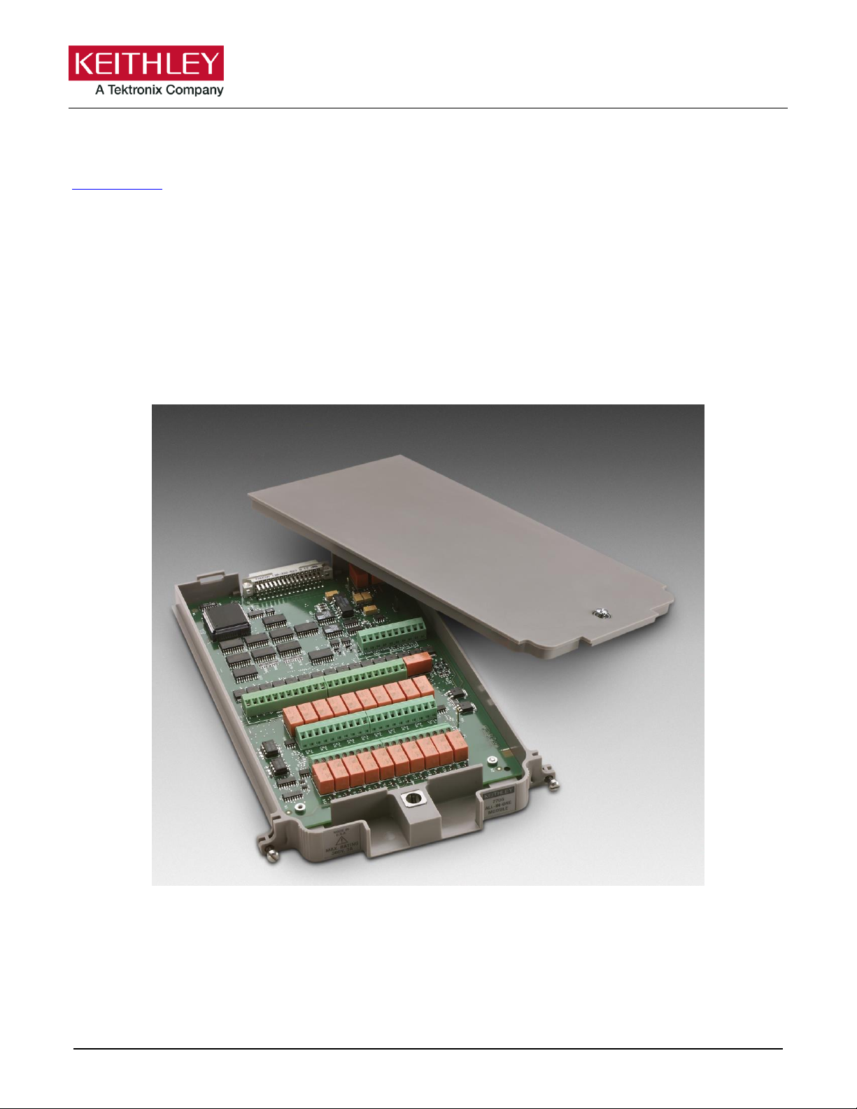
Model 7706 Multiplexer Module
*P077145000* 1
Instructions for use with DAQ6510
Introduction
The 7706 20-Channel Differential Multiplexer switching module offers 20 channels of 2-pole or 10 channels of
4-pole multiplexer switching with automatic CJC. It also offers two analog output channels, 16 digital outputs,
and one event counter/totalizer. You can use the event counter/totalizer to monitor and control system
components while making mixed signal measurements. The 7706 is ideal for RTD, thermistor, and
thermocouple temperature applications.
Figure 1: 7706 Multiplexer Module
Item shipped may vary from model pictured here.
077145000 / June 2018
Page 2
Model 7706 Multiplexer Module Instructions for use with DAQ6510
2
The 7706 includes the following features:
▪ Twenty channels of analog input with 300 V,1 A capacity; 60 W, 125 VA maximum
▪ Sixteen channels of digital output
▪ One event counter/totalizer, which you can use to monitor and control system components and actions,
such as fixtures, limit switches, pass/fail indicators, external voltage sources, loads, door closures, and
revolutions
▪ Two analog outputs (±12 V at 5 mA with 16-bit programmability)
▪ Two-wire or four-wire resistance measurements (automatically pairs switches for four-wire measurements)
▪ Built-in automatic cold junction reference (CJC)
▪ Screw terminal connections
The 7706 can be used with the DAQ6510 Data Acquisition and Multimeter System.
If you are using this switching module with the 2700, 2701, or 2750, please see Model 7706
Multiplexer Card User's Manual, Keithley Instruments document PA-719.
Wiring procedure
Use the following procedure to make connections to the 7706 module. Make all connections using correct wire
size (up to 22 AWG).
Connection and wiring procedures in this document are intended for use by qualified
personnel only, as described by the types of product users in the Safety precautions (on
page 40). Do not perform these procedures unless qualified to do so. Failure to recognize and
observe normal safety precautions could result in personal injury or death.
All wiring must be rated for the maximum voltage in the system. For example, if 1000 V is
applied to the front terminals of the instrument, the switching module wiring must be rated
for 1000 V. Failure to recognize and observe normal safety precautions could result in
personal injury or death.
Do not exceed the maximum specifications for the 7706 module. Refer to the specifications
provided in the data sheet. Failure to recognize and observe normal safety precautions could
result in personal injury or death.
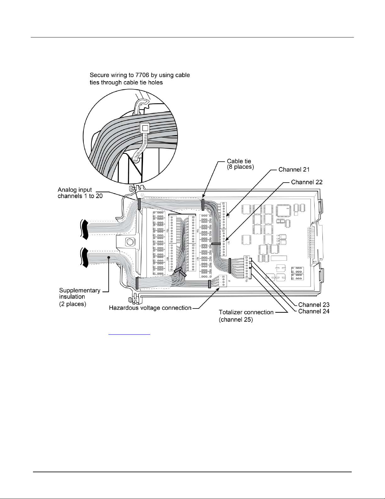
The 7706 module provides connections for both hazardous-voltage and low-voltage circuits.
Make sure to install and maintain double insulation between the hazardous-voltage and
low-voltage wiring using supplementary insulation as required. See the "Wire dressing–fully
wired module" figure in this document for more information. Failure to insulate wiring
properly could result in personal injury or death.
077145000 / June 2018
Page 3

Model 7706 Multiplexer Module Instructions for use with DAQ6510
3
Equipment needed:
▪ Flat-blade screwdriver
▪ Cable ties
To wire the 7706:
1. Make sure all power is discharged from the 7706 module.
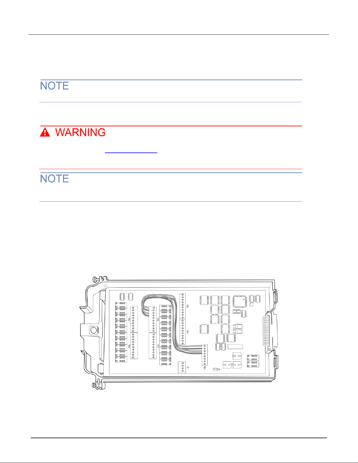
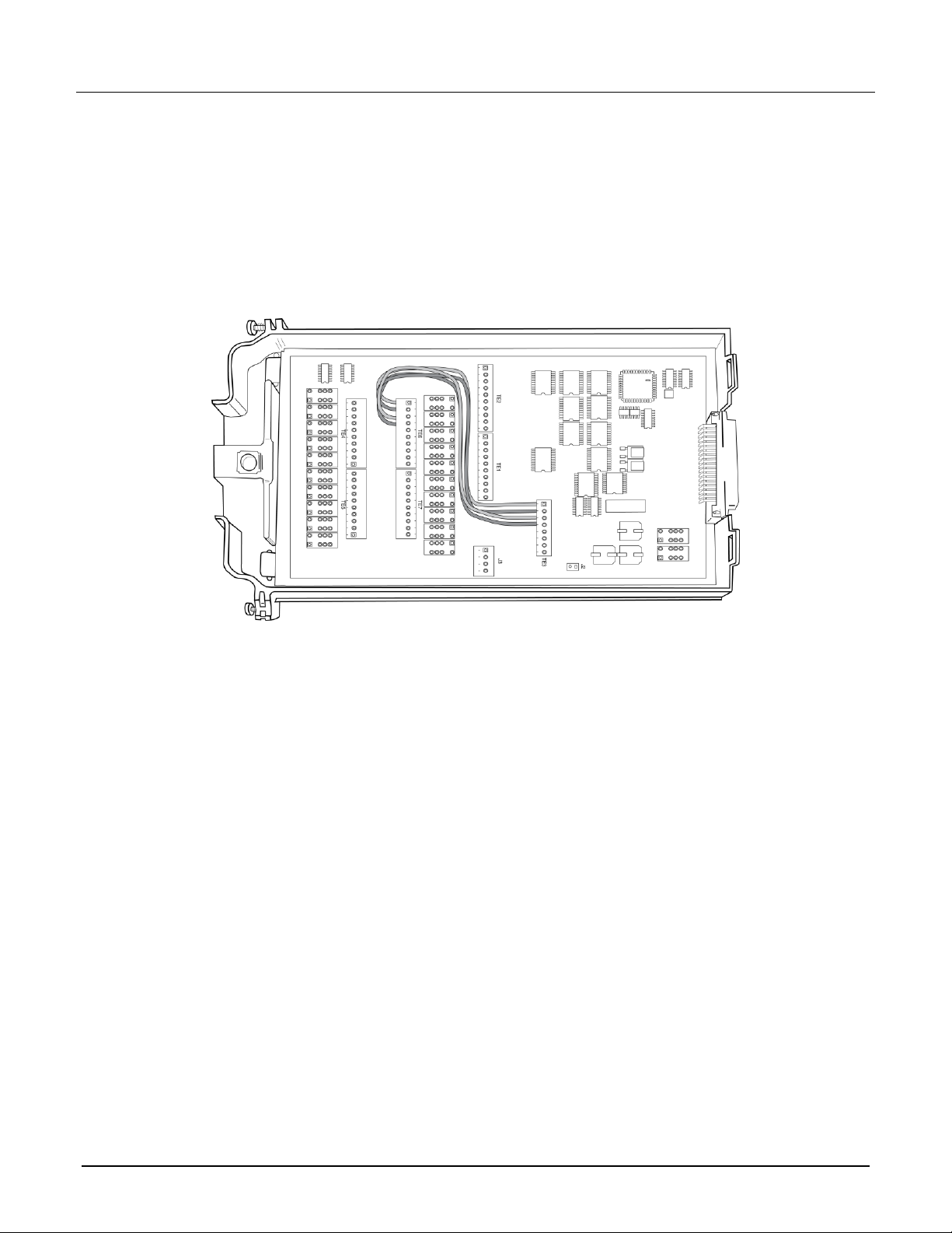
2. Using a screwdriver, turn the access screw to unlock and open the cover.
Figure 2: Screw terminal access
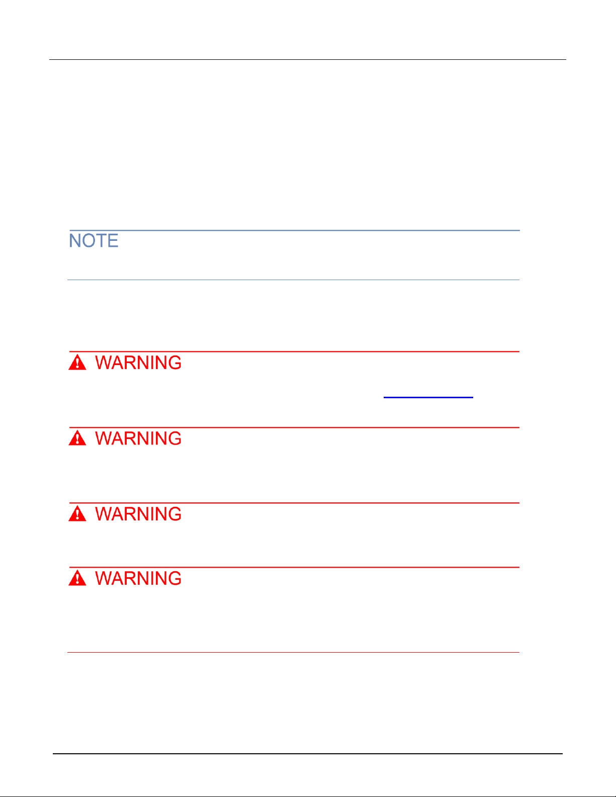
3. Using the flat-blade screwdriver, loosen the terminal screws and install the wires as needed. The channel
designations for the screw terminals are shown in the following figures.
077145000 / June 2018
Page 4
Model 7706 Multiplexer Module Instructions for use with DAQ6510
4
Figure 3: Channel designations for analog inputs
077145000 / June 2018
Page 5
Model 7706 Multiplexer Module Instructions for use with DAQ6510
5
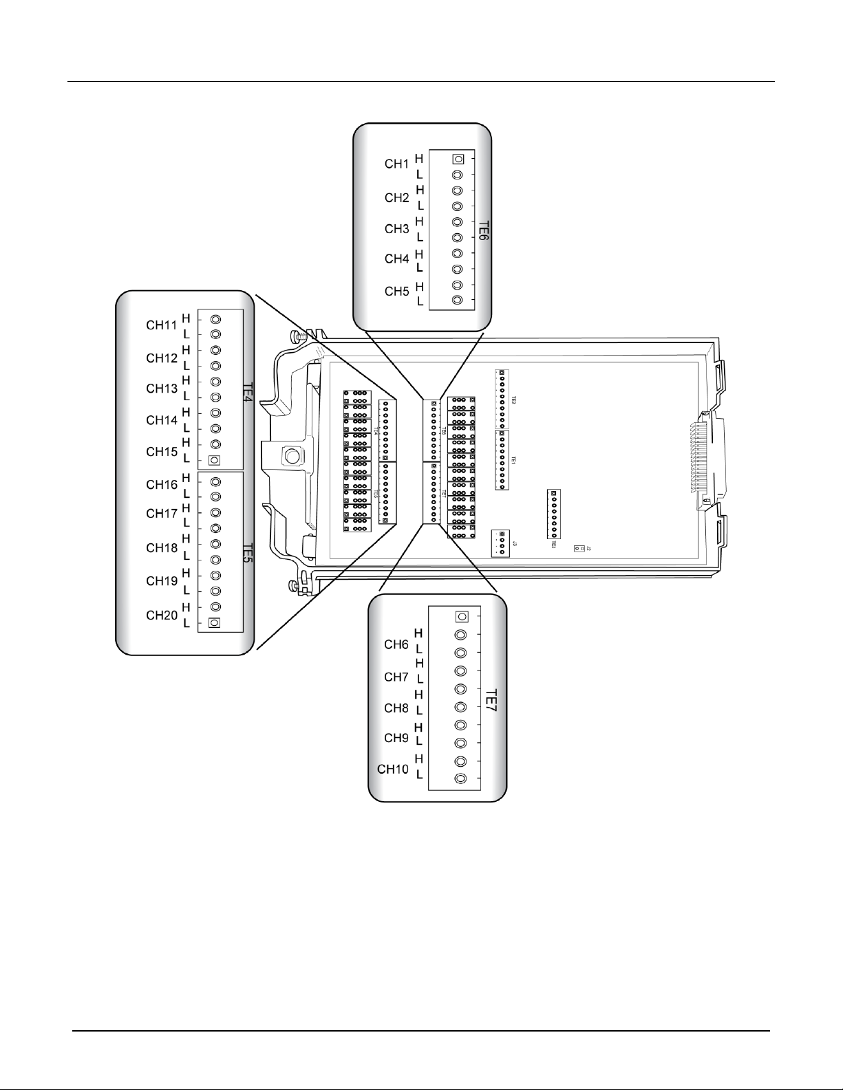
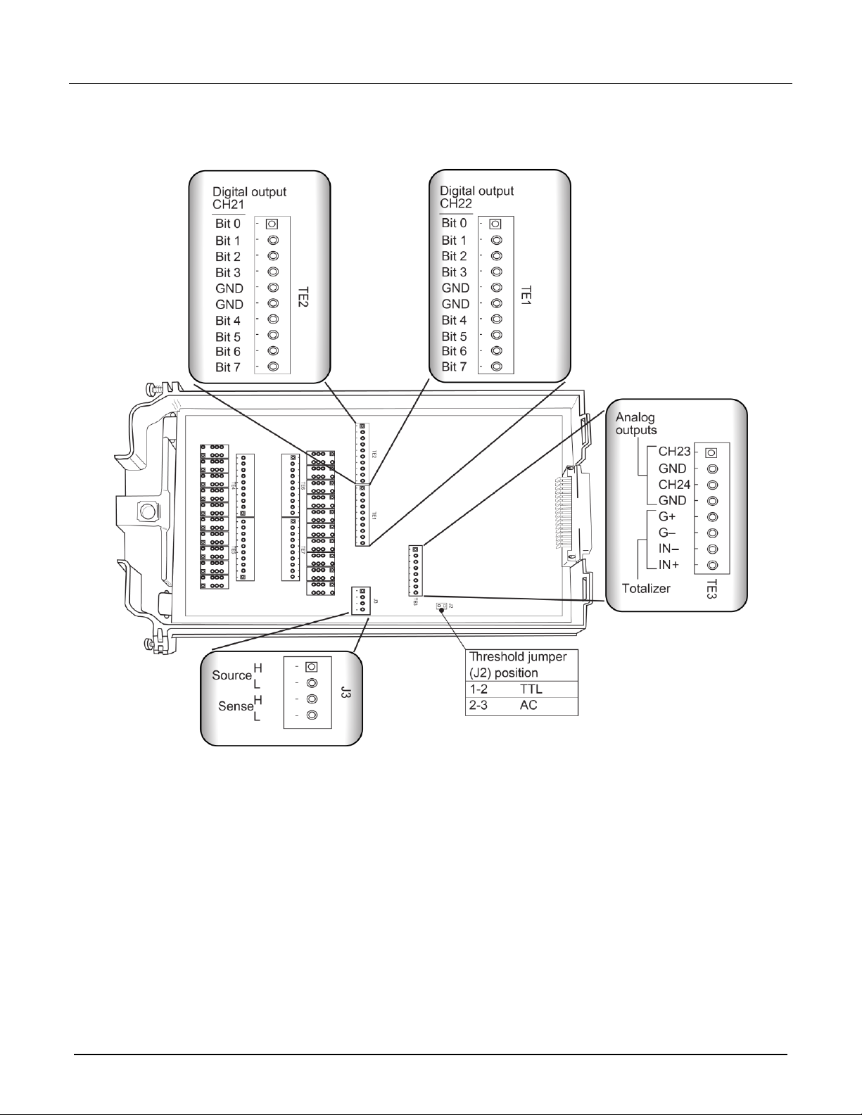
Figure 4: 7706 screw terminal output, source, and sense channel designations
077145000 / June 2018
Page 6
Model 7706 Multiplexer Module Instructions for use with DAQ6510
6
4. Route the wire along the wire path and secure with cable ties as shown in the following figure.
Figure 5: Wire dressing - fully wired module
5. Fill in a copy of the Connection log (on page 22).
6. Attach the screw terminal access cover.
7. Using a screwdriver, press in the access screw and turn to lock the cover.
077145000 / June 2018
Page 7

Model 7706 Multiplexer Module Instructions for use with DAQ6510
7
7706 simplified schematic
The 7706 has channels that are grouped into two banks of ten channels (twenty channels total). Backplane
isolation is provided for each bank. Each bank also includes separate cold junction reference points. The first
bank contains channels 1 to 10, while the second bank contains channels 11 to 20. Each channel of the
20-channel multiplexer module is wired with separate inputs for HI and LO, providing fully isolated inputs.
Connections to DMM functions are provided through the module backplane connector for the INPUT
connections and SENSE (4-wire resistance) connections.
Channels 21 to 22 (digital output), 23 to 24 (analog output), and 25 (totalizer) are controlled either using the
remote interface or from the front panel. The grounds for these channels are non-isolated. Detailed information
for each channel is provided later in this document.
Channel 26 (2-wire or 4-wire configuration), channel 27 (sense isolation), and channel 28 (input isolation) are
normally automatically configured by the DAQ6510. However, if the module is not to be connected to the
internal DMM, you can control the channels independently. Note that in the schematic, channels 26, 27, and 28
refer to the designations used for control and not actual available channels. For more information, refer to the
instrument reference manual section "Multiple channel operation."
Connect 4-wire sense leads using channels 11 to 20. When the instrument is configured for 4-wire
measurements (including 4-wire resistance, RTD temperature, ratio, and channel average), the channels are
paired as follows:
▪ CH1 and CH11
▪ CH2 and CH12
▪ CH3 and CH13
▪ CH4 and CH14
▪ CH5 and CH15
▪ CH6 and CH16
▪ CH7 and CH17
▪ CH8 and CH18
▪ CH9 and CH19
▪ CH10 and CH20
Although the 7706 relays are latching (the relays hold their state even after power has been
removed), all relay states are set to open a few seconds after either a power cycle or a reset
command is issued.
077145000 / June 2018
Page 8

Model 7706 Multiplexer Module Instructions for use with DAQ6510
8
Figure 6: 7706 simplified schematic
077145000 / June 2018
Page 9

Model 7706 Multiplexer Module Instructions for use with DAQ6510
9
Channels
Description
1 to 20
Measurements such as voltage, resistance, temperature, frequency, and period
21 to 22
Eight-bit digital outputs
23 to 24
Sixteen-bit analog outputs (DAC)
25
Totalizer
26
Two-pole or four-pole selection relay; closing channel 26 makes a four-pole measurement
27
Sense terminals to backplane isolation
28
Input terminals to backplane isolation
Channel usage
When using remote communications to send commands, be aware of the following channel usage.
Installation
Before operating an instrument with a switching module, verify that the switching module is
properly installed and the mounting screws are tightly fastened. If the mounting screws are
not properly connected, an electrical shock hazard may be present.
If you are installing two switching modules, it is easier to install one switching module into slot 2 first, then install
the second switching module into slot 1.
If you have a Keithley Instruments Model 2700, 2701, or 2750 instrument, you can use your existing
switching module in the DAQ6510. Follow the instructions in your original equipment documentation
to remove the module from the instrument, then use the following instructions to install it in the
DAQ6510. You do not need to remove wiring to the module.
For inexperienced users, it is recommended that you do not connect a device under test (DUT) and
external circuitry to the switching module. This allows you to exercise close and open operations
without the dangers associated with live test circuits. You can also set up pseudocards to experiment
with switching. Refer to "Pseudocards" in the Model DAQ6510 Data Acquisition and Multimeter
System Reference Manual for information on setting up pseudocards.
To prevent electric shock that could result in injury or death, never handle a switching
module that has power applied to it. Before installing or removing a switching module, make
sure the DAQ6510 is turned off and disconnected from line power. If the switching module is
connected to a DUT, make sure power is removed from all external circuitry.
If a card slot is unused, you must install slot covers to prevent personal contact with high
voltage circuits. Failure to install slot covers could result in personal exposure to hazardous
voltages, which could cause personal injury or death if contacted.
077145000 / June 2018
Page 10
Model 7706 Multiplexer Module Instructions for use with DAQ6510
10
Before installing or removing a switching module, make sure the DAQ6510 power is turned
off and disconnected from line power. Failure to comply may result in incorrect operation and
loss of data in the memory.
Required equipment:
▪ Medium flat-blade screwdriver
▪ Medium Phillips screwdriver
To install a switching module into the DAQ6510:
1. Turn off the DAQ6510.
2. Disconnect the power cord from the power source.
3. Disconnect the power cord and any other cables that are connected to the rear panel.
4. Position the DAQ6510 so you are facing the rear panel.
5. Use the screwdriver to remove the slot cover screws and the cover plate. Retain the plate and screws for
future use.
6. With the top cover of the switching module facing up, slide the switching module into the slot.
7. Press the switching module in firmly to make sure the switching module connector is connected to the
DAQ6510 connector.
8. Use the screwdriver to tighten the two mounting screws to secure the switching module to the mainframe.
Do not overtighten.
9. Reconnect the power cord and any other cables.
Remove a switching module
Before you remove a switching module or begin any testing, make sure that all of the relays are
open. Since some relays may be latched closed, you must open all of the relays before removing the
switching module to make connections. Additionally, if you drop your switching module, it is possible
for some relays to latch closed.
To open all channel relays, go to the CHANNEL swipe screen. Select Open All.
To prevent electric shock that could result in injury or death, never handle a switching
module that has power applied to it. Before installing or removing a switching module, make
sure the DAQ6510 is turned off and disconnected from line power. If the switching module is
connected to a DUT, make sure power is removed from all external circuitry.
If a card slot is unused, you must install slot covers to prevent personal contact with high
voltage circuits. Failure to install slot covers could result in personal exposure to hazardous
voltages, which could cause personal injury or death if contacted.
077145000 / June 2018
Page 11

Model 7706 Multiplexer Module Instructions for use with DAQ6510
11
Before installing or removing a switching module, make sure the DAQ6510 power is turned
off and disconnected from line power. Failure to comply may result in incorrect operation and
loss of data in the memory.
Required equipment:
▪ Medium flat-blade screwdriver
▪ Medium Phillips screwdriver
To remove a switching module from the DAQ6510:
1. Turn off the DAQ6510.
2. Disconnect the power cord from the power source.
3. Disconnect the power cord and any other cables that are connected to the rear panel.
4. Position the DAQ6510 so you are facing the rear panel.
5. Use the screwdriver to loosen the mounting screws that secure the switching module to the instrument.
6. Carefully remove the switching module.
7. Install a slot plate or another switching module in the empty slot.
8. Reconnect the power cord and any other cables.
Operation
Before installing or removing a 7706 module, make sure the DAQ6510 power is turned off and
disconnected from line power. Failure to comply may result in incorrect operation and loss of
data in 7706 memory.
This switching module does not support current measurements. If the instrument has the TERMINALS switch
set to REAR and you are working with the slot that contains this switching module, the AC, DC, and digitize
current functions are not available. You can measure current using the front panel or using another slot that
contains a switching module that supports the AC, DC, and digitize current measurements.
If you use remote commands to attempt to measure current when configuring a channel, an error is returned.
Typical connections (channels 1 to 20)
The following examples show typical wiring connections for the following types of measurements:
▪ Thermocouple
▪ Two-wire resistance and thermistor
▪ Four-wire resistance and RTD
▪ DC or AC voltage
077145000 / June 2018
Page 12

Model 7706 Multiplexer Module Instructions for use with DAQ6510
12
Thermocouple connections
Figure 7: Thermocouple connections
Two-wire resistance and thermistor connections
Figure 8: Two-wire resistance and thermistor connections
077145000 / June 2018
Page 13
Model 7706 Multiplexer Module Instructions for use with DAQ6510
13
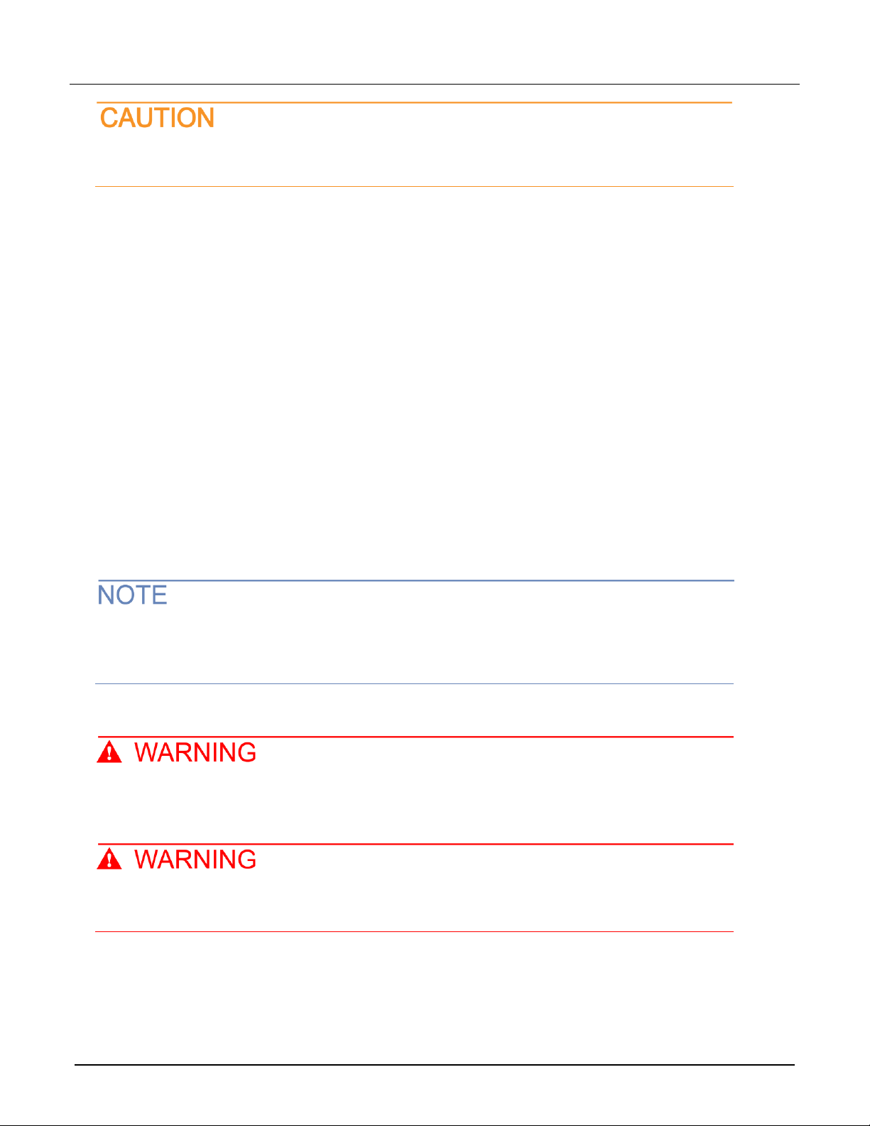
Four-wire resistance and RTD connections
Figure 9: Four-wire resistance and RTD connections
DC or AC voltage connections
Figure 10: DC or AC voltage connections
077145000 / June 2018
Page 14

Model 7706 Multiplexer Module Instructions for use with DAQ6510
14
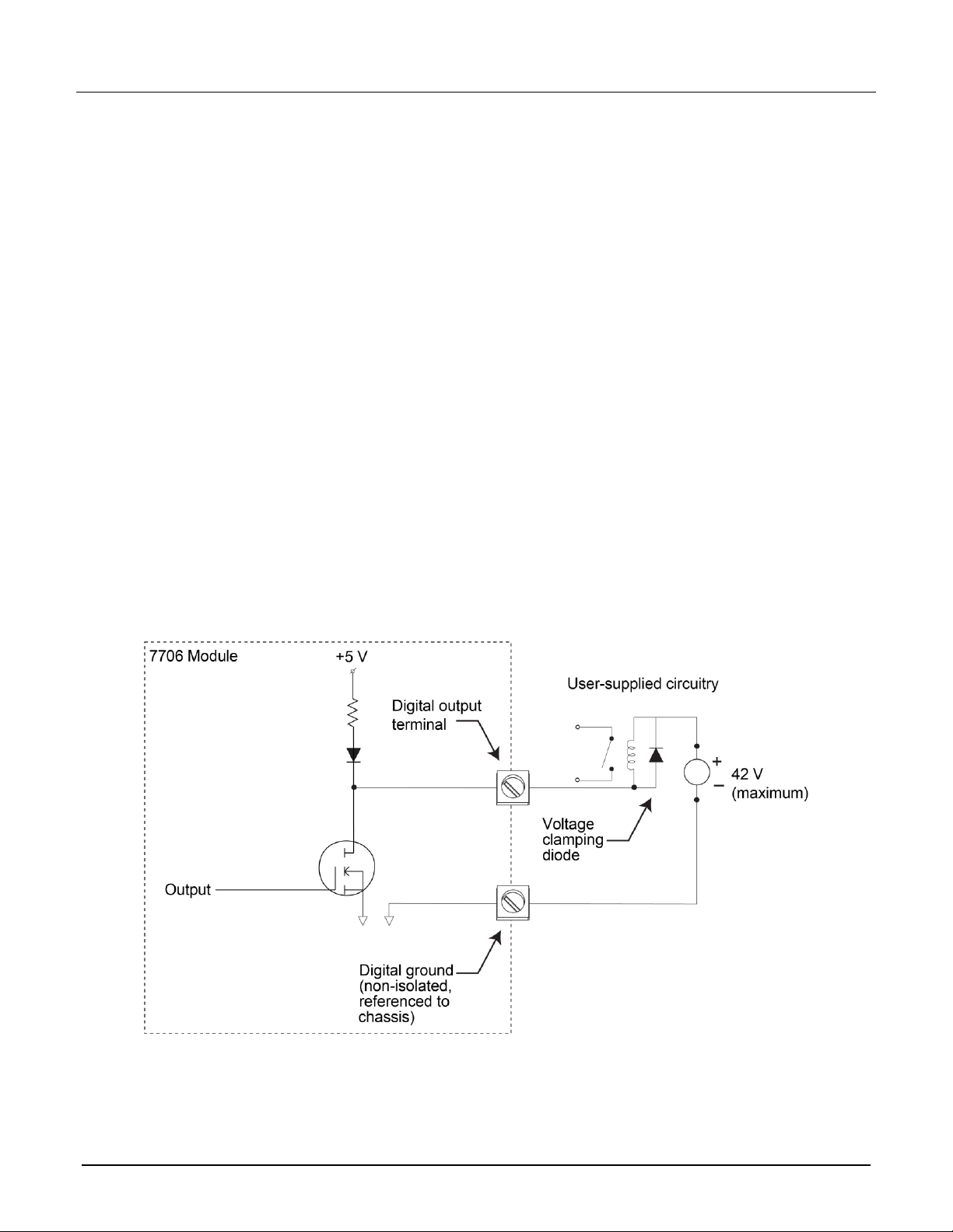
Digital outputs (channels 21 to 22)
Use the 7706 digital outputs to control items such as indicators, fixtures, switches, solenoids, loads, and relays.
The following figure shows a simplified schematic of the digital output.
Figure 11: Simplified schematic of the digital output
The digital output allows the use of an external power supply up to 42 V.
077145000 / June 2018
Page 15
Model 7706 Multiplexer Module Instructions for use with DAQ6510
15
Set the digital outputs in 8-bit (byte)
To set the digital output, send the decimal equivalent of the binary pattern.
On each port, bit 7 is the most significant bit (MSB) and bit 0 is the least significant bit (LSB). This makes the
pin 1 screw terminal of each digital port (TE2 and TE1) the LSB, and pin 10 the MSB.
TE2 is channel 21 and TE1 is channel 22. Pins 5 and 6 on each digital port are ground.
To find the decimal equivalent of the binary pattern send the decimal value using the remote interface (as in the
example) or by using the front panel of the DAQ6510.
077145000 / June 2018
Page 16

Model 7706 Multiplexer Module Instructions for use with DAQ6510
16
Set digital value
You can set a digital value using the front panel or remote commands. The following examples are for a card in
slot 1. If the switching module is in slot 2, replace channel 121 with channel 221.
Using the front panel:
1. Press the HOME key.
2. On the NON-SWITCH swipe screen, select Write.
3. Select channel 121 and select OK.
4. Enter 138 and select OK.
To verify using the front panel:
1. On the NON-SWITCH swipe screen, select Read.
2. Select channel 121 and then select OK. The result displays.
Using SCPI commands:
ROUTe:CHANnel:WRITe 138, (@121)
ROUTe:CHANnel:READ? (@121)
Using TSP commands:
channel.write("121", 138)
print(channel.read("121"))
077145000 / June 2018
Page 17

Model 7706 Multiplexer Module Instructions for use with DAQ6510
17
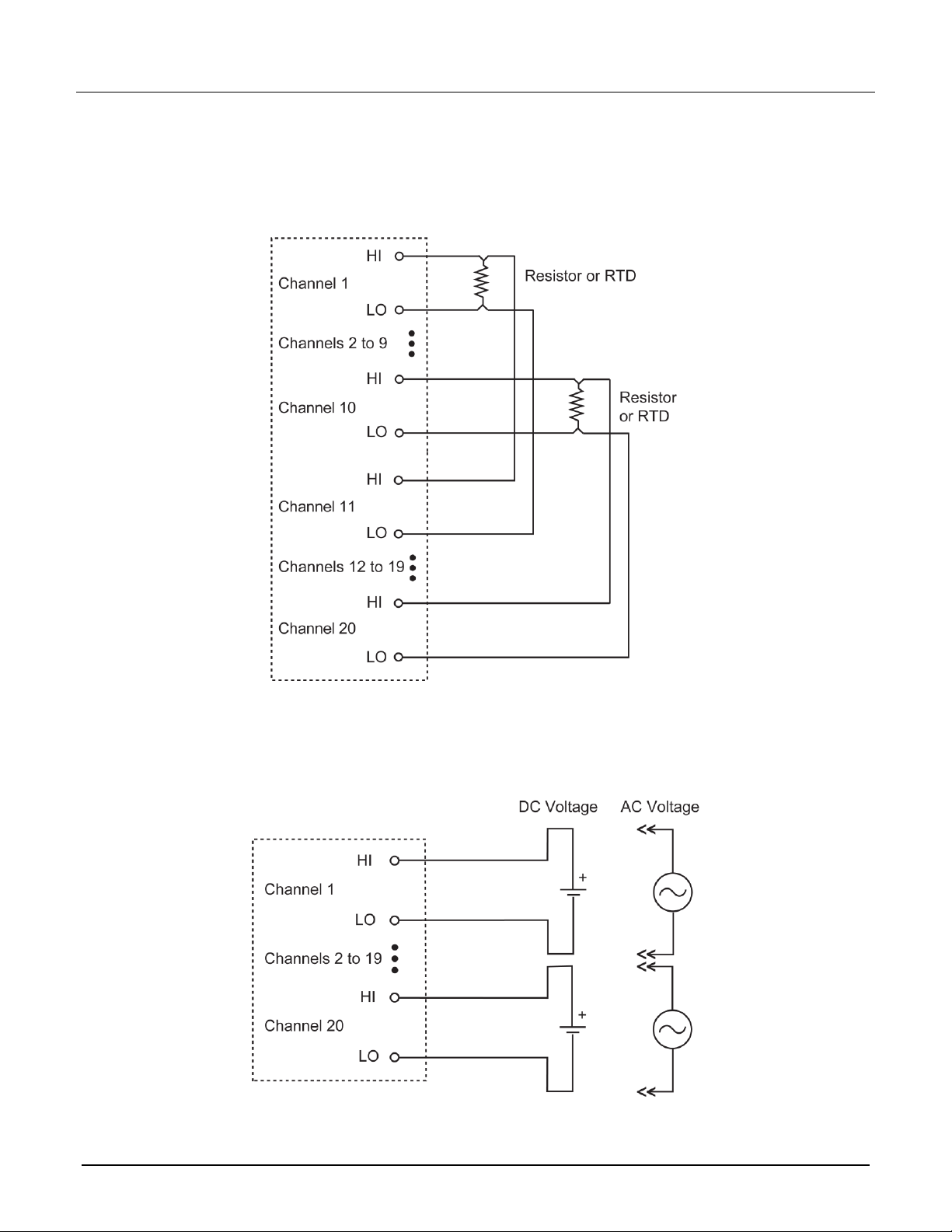
Setting the digital outputs in 16-bit (word)
To set the digital outputs in 16-bit, send the decimal equivalent of the binary pattern (similar to 8-bit). The binary
pattern is twice as long as the 8-bit pattern (requiring both digital output ports). Bit 15 is the most significant bit
(MSB) and bit 0 is the least significant bit (LSB). This makes the pin 1 screw terminal of channel 21 (TE2) the
LSB and the pin 10 screw terminal of channel 22 (TE1) the MSB.
To find the decimal equivalent of the binary pattern:
1. Determine the pattern mapped to the screw terminals on the digital output (refer to the example in the
following figure). Setting a bit to a logic 1 effectively sets the screw terminal to +5 V, while setting it to a
logic 0 sets the screw terminal to 0 V.
2. For each screw terminal (or bit position), multiply the binary value (either a 1 or a 0) by the decimal weight,
as shown in the following figure. The sum of the products is the decimal equivalent value of the binary
pattern. This decimal value can be sent using the remote interface as in the example.
077145000 / June 2018
Page 18
Model 7706 Multiplexer Module Instructions for use with DAQ6510
18
Set a 16-bit digital value
You can set a 16-bit digital value using the front panel or remote commands. The following examples are for a
card in slot 1. If the switching module is in slot 2, replace channel 121 with channel 221.
Using the front panel:
1. Press the MENU key.
2. Under the Channel column, select Settings.
3. Select channel 121.
4. Select Width and enter 2.
5. Press the HOME key.
6. On the NON-SWITCH swipe screen, select Write.
7. Select channel 121.
8. Enter 49288 and select OK.
9. On the NON-SWITCH swipe screen, select Read.
10. Select channel 121 and select OK. The result displays in hexadecimal.
Using SCPI commands:
ROUTe:WIDTh 2, (@121)
ROUTe:CHANnel:WRITe 49288, (@121)
ROUTe:CHANnel:READ? (@121)
Using TSP commands:
channel.setwidth("121", 2)
channel.write("121", 49288)
print(channel.read("121"))
Figure 12: Typical digital output with external power supply
077145000 / June 2018
Page 19

Model 7706 Multiplexer Module Instructions for use with DAQ6510
19
Figure 13: Typical digital output with no external power supply
Reactive loads
To prevent damage to the module, do not exceed the maximum signal level specifications of
the module. For reactive loads, be sure to use voltage clamping and current surge limiting.
7706 operation is specified for resistive loads. Reactive loads require voltage clamping for inductive loads and
current surge limiting for capacitive loads to prevent damage to the relays and to external circuitry.
077145000 / June 2018
Page 20

Model 7706 Multiplexer Module Instructions for use with DAQ6510
20
Analog outputs (channels 23 to 24)
Analog output current limit is 5 mA (maximum).
The 7706 contains two digital to analog converters (DACs). Use these analog outputs for tasks such as
applying a voltage bias to DUTs or analog control. The two analog outputs of the 7706 can provide voltages in
the range of ±12 V. The analog outputs can be set from the front panel or using the remote interface.
The following figure shows a simplified schematic of the analog outputs.
Figure 14: Analog outputs
In the following examples, the 7706 module is in slot 1 of the DAQ6510.
Sample 1: Set analog output 1 (channel 23) to 10.0 V
The following examples are for a card in slot 1. Set channel 23 (analog output 1).
Using the front panel:
1. Press the HOME key.
2. On the NON-SWITCH swipe screen, select Write.
3. Select channel 123.
4. Enter 10 and select OK.
Using SCPI commands:
ROUTe:CHANnel:WRITe 10.0, (@123)
Using TSP commands:
channel.write("123", 10.0)
Refer to “Front panel operation” in the Model DAQ6510 Reference Manual for more information on
menus and key locations. Voltage may be set in 1 mV steps (values are rounded to the nearest
millivolt).
077145000 / June 2018
Page 21

Model 7706 Multiplexer Module Instructions for use with DAQ6510
21
Sample 2: Set analog output 2 (channel 24) to -5.5 V
The following examples are for a card in slot 1. Set analog output 2 (channel 24).
Using the front panel:
1. Press the HOME key.
2. On the NON-SWITCH swipe screen, select Write.
3. Select channel 124.
4. Enter -5.5 and select OK.
Using SCPI commands:
ROUTe:CHANnel:WRITe -5.5, (@124)
Using TSP commands:
channel.write("124",-5.5)
Note that each output is referenced to the chassis. Each output cannot float from each other. To operate with
the analog output in specification as a calibrated voltage source, the minimum resistance load is 2.4 kΩ. Refer
to the following figure for details.
Figure 15: Sample analog connection schematic
077145000 / June 2018
Page 22

Model 7706 Multiplexer Module Instructions for use with DAQ6510
22
Loading effects
Loading of the voltage source is a consideration for low resistance loads. As the source resistance increases,
the error caused by loading increases. The figure below shows the method used to determine the percent error
due to loading, where:
▪ Vs is the programmed analog output of the 7706
▪ R
▪ R
▪ VM is the measured voltage
is the total lead resistance of the wiring and connections
Lead
is the resistance of your circuit
Load
The voltage actually measured by the meter is attenuated by the voltage divider action of R
can be calculated as follows:
This relationship can be modified to directly compute for percent error:
Using the above equation, to keep loading error within 0.1%, the resistance of the 7706 system must be at least
1/999th the value of load resistance.
Figure 16: Loading effects
Load
and R
Lead
DAC output errors
, and it
The DAC output is most accurate when the 7706 is operated in stable temperature conditions that are as close
as possible to the environmental conditions used for calibration. Offset voltage drift over temperature is
1 mV/°C. The offset voltage value may change when changing from slot 1 to slot 2.
Connection log
You can use the following table to record your connection information.
077145000 / June 2018
Page 23

Model 7706 Multiplexer Module Instructions for use with DAQ6510
23
Channel
Color
Description
INPUT
H
L
SENSE
H
L
CH1
H
L
CH2
H
L
CH3
H
L
CH4
H
L
CH5
H
L
CH6
H
L
CH7
H
L
CH8
H
L
CH9
H
L
CH10
H
L
CH11
H
L
CH12
H
L
CH13
H
L
CH14
H
L
CH15
H
L
CH16
H
L
077145000 / June 2018
Page 24

Model 7706 Multiplexer Module Instructions for use with DAQ6510
24
Channel
Color
Description
CH17
H
L
CH18
H
L
CH19
H
L
CH20
H
L
CH21
B0
B1
B2
B3
B4
B5
B6
B7
GND
CH22
B0
B1
B2
B3
B4
B5
B6
B7
GND
CH23
H
GND
CH24
H
GND
CH25
IN+
IN–
G+
G–
077145000 / June 2018
Page 25

Model 7706 Multiplexer Module Instructions for use with DAQ6510
25
Totalizer
Use the totalizer to count more than 4 billion on/off events, such as contact closures, revolutions, and power
cycles. You can read or write the totalizer count from the front panel or the remote interface. For more
advanced options, use the remote interface. Options available through the remote interface include:
▪ Starting a scan when the totalizer reaches a specific value (SCPI :ROUTe:SCAN:MONitor:CHANnel;
TSP scan.monitor.channel)
▪ Matching values to generate an event (SCPI :ROUTe[:CHANnel]:MATCh and
:ROUTe[:CHANnel]:MATCh:TYPE; TSP channel.getmatch(), channel.setmatch(),
channel.getmatchtype(), and channel.setmatchtype().
▪ Setting the totalizer to count on the falling edge and resetting the totalizer when the count is read (SCPI
:ROUTe[:CHANnel]:MODE; TSP channel.getmode() and channel.setmode()).
. The following figure shows a simplified schematic of the totalizer connected to a function generator.
The totalizer can count exactly up to 4,294,967,295 events (232-1). The count resets (sets its value
to 0) when it reaches 232.
Figure 17: Totalizer simplified schematic
077145000 / June 2018
Page 26
Model 7706 Multiplexer Module Instructions for use with DAQ6510
26
Threshold detection
The totalizer can count events at a rate of up to 100 kHz. The count can be initiated manually or by configuring
a scan. When counting, the totalizer can:
▪ Reset to zero every time it is read.
▪ Count on the rising or falling edge of the input signal.
▪ Count AC or TTL signals.
▪ Be governed by a gate signal.
You can configure the totalizer to read through the front panel or read and reset using remote commands. The
following examples are for a card in slot 1.
Using SCPI commands:
:ROUTe:CHANnel:MODE RISING_RESET, (@125)
:ROUTe:CHANnel:READ? (@125)
Using TSP commands:
channel.setmode("125", channel.MODE_RISING_EDGE_READ_RESET)
print(channel.read("125"))
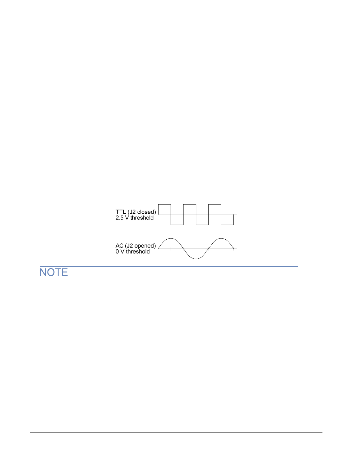
The type of threshold detected by the totalizer is set by the position of jumper J2 (see figure in Wiring
procedure (on page 2)). The factory default setting for this jumper is closed (TTL). The TTL wave and the AC
type wave form are shown in the following figure.
Figure 18: AC and TTL waveform
The totalizer counts when both terminals are either enabled or open. You cannot set threshold
levels.
077145000 / June 2018
Page 27
Model 7706 Multiplexer Module Instructions for use with DAQ6510
27
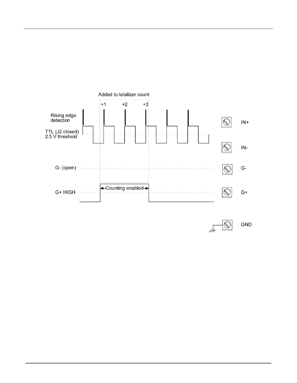
Gating provides specific control over when the totalizer readings are made. A gate is always interpreted if no
gating signal is present. To control counting through the G+ screw terminal, send a TTL high signal to enable
counting and a TTL low signal to disable counting. To control counting through the G screw terminal, send a
TTL low signal to enable counting and a TTL high signal to disable counting. The totalizer can be controlled
from the G+ screw terminal, the G screw terminal, or both (both G+ and G screw terminals must be enabled
to count). Samples of totalizer input with gating are shown in the following figure.
Figure 19: Sample totalizer input with gating
Viewing totalizer count
You can view the totalizer count using the front panel or remote commands. This example reads the totalizer
count. The following example is for a card in slot 1. If the switching module is in slot 2, replace channel 125 with
channel 225.
Using the front panel:
1. Press the HOME key.
2. On the NON-SWITCH swipe screen, select Read.
3. Select channel 125 and select OK.
Using SCPI commands:
:ROUTe:CHANnel:READ? (@125)
Using TSP commands:
print(channel.read("125"))
077145000 / June 2018
Page 28

Model 7706 Multiplexer Module Instructions for use with DAQ6510
28
Scan operation
The limit subsystem and analog scan triggering works the same for the totalize function as for any other
DAQ6510 function, except that only the upper limit is evaluated. The lower limit setting is ignored by the totalize
function. The scan monitor must be set to monitor the totalizer channel in order to initiate a scan based on a
totalizer limit. When a scan is initiated by a totalizer count, and the totalizer type is set to READ, the limit that
initiated the scan is removed from the :ROUTe:SCAN:STARt:STIMulus or scan.start.stimulus list so
that the DAQ6510 only runs through the scan list once. Otherwise, it would keep scanning, since the totalizer
count would remain above the upper limit until reset. The totalizer can be configured to count on the rising or
falling edge of the input signal.
The following examples are for applying the scan monitor mode with a card in slot 1 using the totalizer. It is set
to trigger on the rising edge.
Using SCPI commands:
:ROUTe:SCAN:MONitor:MODE UPPer
:ROUTe:SCAN:MONitor:CHANnel (@125)
:ROUTe:CHANnel:MODE RISing, (@125)
Using TSP commands:
scan.monitor.mode = scan.MODE_HIGH
scan.monitor.channel = "125"
channel.setmode("125", channel.MODE_RISING_EDGE)
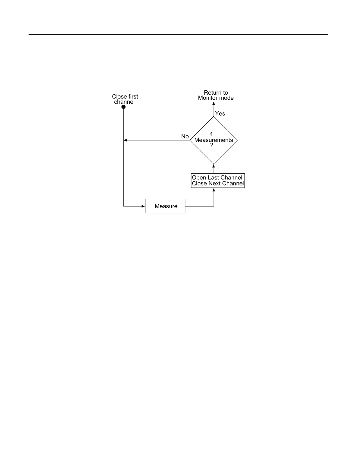
A simplified model of scan operation is in the following figures. For this example, there are two stages of
operation: monitor and scan. The figure below shows monitor operation. While monitoring, continuous totalizing
is active. The instrument remains in the monitor stage until it reaches the high limit. In the following example,
the high limit is set to 99,999 counts.
Figure 20: Monitor mode scan example: Monitor mode
077145000 / June 2018
Page 29
Model 7706 Multiplexer Module Instructions for use with DAQ6510
29
When the limit is exceeded, the instrument starts the scan, as shown in the following figure. The instrument is
configured to scan four channels: three DC voltage readings and the totalizer channel. The reading buffer
stores all four readings.
Figure 21: Monitor scan example: Scan mode
Totalizer channel monitor scan example
For this example, the instrument is set to monitor the totalizer channel of a 7706 installed into slot 1. This is an
example of a four-channel scan, with channels 101 to 105 measuring DC voltage while the scan monitors the
totalizer channel 125. When the totalizer reaches 100,000 counts, the scan is initiated.
077145000 / June 2018
Page 30

Model 7706 Multiplexer Module Instructions for use with DAQ6510
30
*RST
ROUTe:CHANnel:WRITe 0, (@125)
ROUTe:CHANnel:READ? (@125)
SENSe:FUNCtion "VOLTage", (@101:105)
SENSe:VOLTage:NPLC 0.01, (@101:105)
ROUTe:SCAN:MONitor:CHANnel (@125)
ROUTe:SCAN:MONitor:LIMit:UPPer 99999
ROUTe:SCAN:MONitor:MODE UPPer
ROUTe:SCAN:COUNt:SCAN 100
ROUTe:SCAN:CREate (@101:105)
INIT
Reset the instrument.
Set the totalizer to zero.
Verify that the channel was set to 0.
Set DCV to 0.01 PLC on channels 101 to 105.
Set the scan to monitor the totalizer.
Set the upper limit to 99,999.
Set the scan to start after you reach the upper limit.
Set the scan count to 100.
Create a scan that includes channels 101 to 105.
Initiate the scan.
reset()
channel.write("125", 0)
print(channel.read("125"))
channel.setdmm("101:105", dmm.ATTR_MEAS_FUNCTION, dmm.FUNC_DC_VOLTAGE)
channel.setdmm("101:105", dmm.ATTR_MEAS_NPLC, 0.01)
scan.monitor.channel = "125"
scan.monitor.limit.high.value = 99999
scan.monitor.mode = scan.MODE_HIGH
scan.create("101:105")
scan.scancount = 100
trigger.model.initiate()
Reset the instrument.
Set the totalizer to zero.
Verify that the channel was set to 0.
Set DCV to 0.01 PLC on channels 101 to 105.
Set the scan to monitor the totalizer.
Set the upper limit to 99,999.
Set the scan to start after you reach the upper limit.
Set the scan count to 100.
Create a scan that includes channels 101 to 105.
Initiate the scan.
Using SCPI commands:
Using TSP commands:
077145000 / June 2018
Page 31
Model 7706 Multiplexer Module Instructions for use with DAQ6510
31
Verification
Use the procedures in this section to verify the analog outputs or the totalizer.
These verification procedures require that the DAQ6510 be within its calibration interval.
Verify the analog outputs
Do not attempt to perform this procedure unless you are qualified, as described by the types
of product users in the Safety precautions (on page 40). Do not perform these procedures
unless qualified to do so. Failure to recognize and observe normal safety precautions could
result in personal injury or death.
After correctly wiring the 7706, installing it in the instrument, and turning the power on, the instrument
is required to warm up for two hours before proceeding.
To set up the 7706 verification:
1. Connect CH23 H and L outputs to CH1 H and L input terminals (respectively).
2. Connect CH24 H and L outputs to CH2 H and L input terminals (respectively).
3. Close and lock the 7706 cover.
4. Install the 7706 in slot 1 of the DAQ6510.
5. Turn on the DAQ6510.
6. Allow unit to warm up for two hours before proceeding.
Figure 22: Analog connections for verification and calibration
077145000 / June 2018
Page 32

Model 7706 Multiplexer Module Instructions for use with DAQ6510
32
Source DC voltage
Reading limits (1 year, 18 °C to 28 °C),
0.15% of reading + 19 mV
+10 V
+9.966 V to +10.034 V
10 V
10.034 V to 9.966 V
To verify the 7706 analog outputs:
1. Set the front panel TERMINALS switch to the REAR position.
2. Press the HOME key.
3. From the NON-SWITCH swipe screen, select Write.
4. Select channel 123, then OK.
5. Enter the output voltage of +10.
6. Verify the analog output reading is within stated limits (see table below).
7. Enter the output voltage of -10 V.
8. Verify the analog output reading is within stated limits.
9. From the NON-SWITCH swipe screen, select Write.
10. Select channel 124, then OK.
11. Enter the output voltage of +10.
12. Verify the analog output reading is within stated limits (see table below).
13. Enter the output voltage of -10 V.
14. Verify the analog output reading is within stated limits.
To set the analog output levels back to zero, set the output voltage as above, entering 0 as the input value.
Verify the totalizer
Do not attempt to perform this procedure unless you are qualified, as described by the types
of product users in the Safety precautions (on page 40). Do not perform these procedures
unless qualified to do so. Failure to recognize and observe normal safety precautions could
result in personal injury or death.
077145000 / June 2018
Page 33

Model 7706 Multiplexer Module Instructions for use with DAQ6510
33
To verify the totalizer:
1. Connect the function generator to the totalizer IN+ and INterminals, as shown in the figure below. Leave
gate inputs (G+ and G) open (gate always).
2. Set the threshold jumper to the TTL position (J2 closed).
3. Close and lock the 7706 cover.
Make sure the DAQ6510 is off before installing the 7706.
4. Install the 7706 in slot 1 of the DAQ6510.
5. Turn on the DAQ6510.
6. Set the front panel TERMINALS switch to REAR position.
7. Set the function generator to:
▪ Burst mode
▪ Burst cycle count of 50,000
▪ Manual trigger source
▪ Output 100 kHz
▪ 0 V to 5 V square wave (50% duty cycle)
8. Press the HOME key.
9. On the NON-SWITCH swipe screen, select Write, then select channel 125 and select OK.
10. Enter 0 and select OK.
11. On the NON-SWITCH swipe screen, select Read, then select channel 125 and select OK.
12. Verify that 0 is displayed.
13. Trigger the function generator.
14. Verify the totalizer count increases by 50,000.
077145000 / June 2018
Page 34

Model 7706 Multiplexer Module Instructions for use with DAQ6510
34
Figure 23: Verification - Totalizer connections
077145000 / June 2018
Page 35

Model 7706 Multiplexer Module Instructions for use with DAQ6510
35
Calibration
Use the following procedures to calibrate the temperature sensors and analog outputs of the 7706.
You must use remote communications and the SCPI command set to calibrate modules. For information on
setting up remote communications, refer to "Remote communications interfaces" in the Model DAQ6510
Reference Manual.
For information on setting the command set, refer to "Determining the command set you will use," also in the
Model DAQ6510 Reference Manual.
Do not attempt to perform this procedure unless you are qualified, as described by the types
of product users in the Safety precautions (on page 40). Do not perform these procedures
unless qualified to do so. Failure to recognize and observe normal safety precautions could
result in personal injury or death.
Recommended test equipment
To calibrate the 7706, you need the following equipment:
▪ Digital thermometer: 18 °C to 28 °C ±0.1 °C
▪ Keithley Instruments 7797 Calibration Extender Board
Extender board connections
The extender board is installed in the DAQ6510 and the 7706 module is connected to the 7797
Calibration/Extender Board externally to prevent heating of the module during calibration.
To make extender board connections:
1. Remove power from the DAQ6510.
2. Install the extender board into slot 1 of the instrument.
3. Plug the module being calibrated to the P1000 connector on the 7797.
077145000 / June 2018
Page 36

Model 7706 Multiplexer Module Instructions for use with DAQ6510
36
Temperature sensor calibration
Before calibrating the temperature sensor on the 7706, make sure that power has been removed
from the module for at least two hours to allow module circuitry to cool down. After turning on the
power during the calibration procedure, complete the procedure as quickly as possible to minimize
module heating that could affect calibration accuracy. Initially allow the DAQ6510 to warm up for at
least two hours with the 7797 calibration card installed. If you are calibrating multiple modules, power
off the DAQ6510, quickly unplug the previously calibrated 7706, and plug in the next one. Wait five
minutes before calibrating the 7706.
Set up calibration:
1. Turn on the DAQ6510 power.
2. To ensure the box is using the SCPI command set, send:
*LANG SCPI
3. Reboot the instrument.
4. On the front panel, verify that TERMINALS is set to REAR.
5. Allow five minutes for thermal equilibrium.
To calibrate temperature:
1. Accurately measure and record the cold temperature of the 7706 module surface at the center of the
module with the digital thermometer.
2. To unlock calibration, send:
:CALibration:PROTected:CODE "KI006510"
3. Calibrate temperature on the 7706 with the following command, where <temp> is the cold calibration
temperature in Celsius measured in step 1 above:
:CALibration:PROTected:CARD1:STEP0 <temp>
4. Send the following commands to save and lock out calibration:
:CALibration:PROTected:CARD1:SAVE
:CALibration:PROTected:CARD1:LOCK
5. To return to the TSP command set, send:
*LANG TSP
6. To return to SCPI 2700 emulation mode, send:
*LANG SCPI2700
7. To return to SCPI 2701 emulation mode, send:
LANG SCPI2701
8. If you changed the command set, reboot the instrument.
077145000 / June 2018
Page 37
Model 7706 Multiplexer Module Instructions for use with DAQ6510
37
Analog output (DAC) calibration
Set up calibration:
1. On the 7706 module, connect the channel 23 H and L outputs to the channel 1 H and L terminals (H to H; L
to L). Refer to the following figure.
2. Connect the channel 24 H and L terminals to the channel 2 H and L terminals (H to H; L to L). Refer to the
following figure.
Figure 24: Analog connections for verification and calibration
3. Remove power from the DAQ6510.
4. Install the 7706 in slot 1.
5. Turn on the DAQ6510 power.
6. To ensure the instrument is using the SCPI command set, send:
*LANG SCPI
7. Reboot the DAQ6510.
8. On the front panel, verify that TERMINALS is set to REAR.
9. Allow instrument to warm up for two hours.
077145000 / June 2018
Page 38

Model 7706 Multiplexer Module Instructions for use with DAQ6510
38
Run calibration:
1. To unlock calibration, send:
:CALibration:PROTected:CODE "KI006510"
2. To calibrate the 7706 analog output, send
:CALibration:PROTected:CARD1:DAC:STEP0
3. Send the following commands to save and lock out calibration:
:CALibration:PROTected:CARD1:SAVE
:CALibration:PROTected:CARD1:LOCK
4. To return to the TSP command set, send:
*LANG TSP
5. To return to SCPI 2700 emulation mode, send:
*LANG SCPI2700
6. To return to SCPI 2701 emulation mode, send:
LANG SCPI2701
7. If you changed the command set, reboot the instrument.
Detect calibration step completion
When you send remote calibration commands, you must wait until the instrument completes the present
operation before sending a command. You can use either *OPC? or *OPC to help determine when each
calibration step is completed.
With the *OPC? (operation complete) query, the instrument places an ASCII 1 in the output queue when it has
completed each step.
To determine when the OPC response is ready:
1. Repeatedly test the MAV (Message Available) bit (bit 4) in the status byte and wait until it is set. You can
request the status byte by using the *STB? query or by serial polling.
2. When MAV is set, a message is available in the output queue, and you can read the output queue and test
for an ASCII 1.
3. After reading the output queue, repeatedly test MAV again until it clears. At this point, the calibration step is
completed.
You can also use the *OPC (operation complete) command to detect the completion of each calibration step.
077145000 / June 2018
Page 39

Model 7706 Multiplexer Module Instructions for use with DAQ6510
39
Error number
Error text
5527
Temperature Cold Cal error
5528
Analog output zero error
5529
Analog output pos. gain error
5530
Analog output neg. gain error
To use *OPC to detect the end of each calibration step:
1. Enable operation complete by sending *ESE 1. This command sets the OPC (operation complete bit) in the
standard event enable register, allowing operation complete status from the standard event status register
to set the ESB (event summary bit) in the status byte when operation complete is detected.
2. Send the *OPC command immediately following each calibration command. For example:
:CALibration:PROTected:DC:STEP1;*OPC
You must include the semicolon (;) to separate the two commands. The *OPC command must be on
the same line as the calibration command.
3. After sending a calibration command, repeatedly test the ESB (Event Summary) bit (bit 5) in the status byte
until it is set. Use either the *STB? query or serial polling to request the status byte.
4. Once operation complete has been detected, clear OPC status using one of two methods:
▪ Use the *ESR? query, then read the response to clear the standard event status register.
▪ Send the *CLS command to clear the status registers. Note that sending *CLS also clears the error
queue and operation complete status.
You can generate an SRQ on calibration complete to detect operation complete instead of repeatedly polling
the DAQ6510. To use this method, send both *ESE 1 and *SRE 32 to the instrument, then include the *OPC
command at the end of each calibration command line, as described above. Refer to the documentation for
your GPIB controller for information on detecting and servicing SRQs.
Errors that can occur during calibration
If calibration errors occur, they are reported in the event log. You can review the event log from the front panel
of the instrument by using the SCPI :SYSTem:EVENtlog:NEXT? command or the TSP eventlog.next()
command.
The following errors can occur.
If one of these errors occurs, contact Keithley Instruments. Refer to Factory service (on page 39).
Factory service
To return the switching module to Keithley Instruments for repair:
▪ Call the Repair Department at 1-800-833-9200 or send an email to RMAREQUEST@tektronix.com for a
Return Material Authorization (RMA) number.
▪ Carefully pack the instrument in the original packing carton.
▪ Write ATTENTION REPAIR DEPARTMENT and the RMA number on the shipping label.
077145000 / June 2018
Page 40

40
Safety precautions
The following safety precautions should be observed before using this product and any associated instrumentation. Although
some instruments and accessories would normally be used with nonhazardous voltages, there are situations where hazardous
conditions may be present.
This product is intended for use by personnel who recognize shock hazards and are familiar with the safety precautions required
to avoid possible injury. Read and follow all installation, operation, and maintenance information carefully before using the
product. Refer to the user documentation for complete product specifications.
If the product is used in a manner not specified, the protection provided by the product warranty may be impaired.
The types of product users are:
Responsible body is the individual or group responsible for the use and maintenance of equipment, for ensuring that the
equipment is operated within its specifications and operating limits, and for ensuring that operators are adequately trained.
Operators use the product for its intended function. They must be trained in electrical safety procedures and proper use of the
instrument. They must be protected from electric shock and contact with hazardous live circuits.
Maintenance personnel perform routine procedures on the product to keep it operating properly, for example, setting the line
voltage or replacing consumable materials. Maintenance procedures are described in the user documentation. The procedures
explicitly state if the operator may perform them. Otherwise, they should be performed only by service personnel.
Service personnel are trained to work on live circuits, perform safe installations, and repair products. Only properly trained
service personnel may perform installation and service procedures.
Keithley products are designed for use with electrical signals that are measurement, control, and data I/O connections, with low
transient overvoltages, and must not be directly connected to mains voltage or to voltage sources with high transient
overvoltages. Measurement Category II (as referenced in IEC 60664) connections require protection for high transient
overvoltages often associated with local AC mains connections. Certain Keithley measuring instruments may be connected to
mains. These instruments will be marked as category II or higher.
Unless explicitly allowed in the specifications, operating manual, and instrument labels, do not connect any instrument to mains.
Exercise extreme caution when a shock hazard is present. Lethal voltage may be present on cable connector jacks or test
fixtures. The American National Standards Institute (ANSI) states that a shock hazard exists when voltage levels greater than
30 V RMS, 42.4 V peak, or 60 VDC are present. A good safety practice is to expect that hazardous voltage is present in any
unknown circuit before measuring.
Operators of this product must be protected from electric shock at all times. The responsible body must ensure that operators
are prevented access and/or insulated from every connection point. In some cases, connections must be exposed to potential
human contact. Product operators in these circumstances must be trained to protect themselves from the risk of electric shock. If
the circuit is capable of operating at or above 1000 V, no conductive part of the circuit may be exposed.
Do not connect switching cards directly to unlimited power circuits. They are intended to be used with impedance-limited
sources. NEVER connect switching cards directly to AC mains. When connecting sources to switching cards, install protective
devices to limit fault current and voltage to the card.
Before operating an instrument, ensure that the line cord is connected to a properly-grounded power receptacle. Inspect the
connecting cables, test leads, and jumpers for possible wear, cracks, or breaks before each use.
When installing equipment where access to the main power cord is restricted, such as rack mounting, a separate main input
power disconnect device must be provided in close proximity to the equipment and within easy reach of the operator.
For maximum safety, do not touch the product, test cables, or any other instruments while power is applied to the circuit under
test. ALWAYS remove power from the entire test system and discharge any capacitors before: connecting or disconnecting
cables or jumpers, installing or removing switching cards, or making internal changes, such as installing or removing jumpers.
Do not touch any object that could provide a current path to the common side of the circuit under test or power line (earth)
ground. Always make measurements with dry hands while standing on a dry, insulated surface capable of withstanding the
voltage being measured.
077145000 / June 2018
Page 41

41
For safety, instruments and accessories must be used in accordance with the operating instructions. If the instruments or
accessories are used in a manner not specified in the operating instructions, the protection provided by the equipment may be
impaired.
Do not exceed the maximum signal levels of the instruments and accessories. Maximum signal levels are defined in the
specifications and operating information and shown on the instrument panels, test fixture panels, and switching cards.
When fuses are used in a product, replace with the same type and rating for continued protection against fire hazard.
Chassis connections must only be used as shield connections for measuring circuits, NOT as protective earth (safety ground)
connections.
If you are using a test fixture, keep the lid closed while power is applied to the device under test. Safe operation requires the use
of a lid interlock.
If a screw is present, connect it to protective earth (safety ground) using the wire recommended in the user documentation.
The symbol on an instrument means caution, risk of hazard. The user must refer to the operating instructions located in the
user documentation in all cases where the symbol is marked on the instrument.
The symbol on an instrument means warning, risk of electric shock. Use standard safety precautions to avoid personal
contact with these voltages.
The symbol on an instrument shows that the surface may be hot. Avoid personal contact to prevent burns.
The symbol indicates a connection terminal to the equipment frame.
If this symbol is on a product, it indicates that mercury is present in the display lamp. Please note that the lamp must be
properly disposed of according to federal, state, and local laws.
The WARNING heading in the user documentation explains hazards that might result in personal injury or death. Always read
the associated information very carefully before performing the indicated procedure.
The CAUTION heading in the user documentation explains hazards that could damage the instrument. Such damage may
invalidate the warranty.
The CAUTION heading with the symbol in the user documentation explains hazards that could result in moderate or minor
injury or damage the instrument. Always read the associated information very carefully before performing the indicated
procedure. Damage to the instrument may invalidate the warranty.
Instrumentation and accessories shall not be connected to humans.
Before performing any maintenance, disconnect the line cord and all test cables.
To maintain protection from electric shock and fire, replacement components in mains circuits — including the power
transformer, test leads, and input jacks — must be purchased from Keithley. Standard fuses with applicable national safety
approvals may be used if the rating and type are the same. The detachable mains power cord provided with the instrument may
only be replaced with a similarly rated power cord. Other components that are not safety-related may be purchased from other
suppliers as long as they are equivalent to the original component (note that selected parts should be purchased only through
Keithley to maintain accuracy and functionality of the product). If you are unsure about the applicability of a replacement
component, call a Keithley office for information.
Unless otherwise noted in product-specific literature, Keithley instruments are designed to operate indoors only, in the following
environment: Altitude at or below 2,000 m (6,562 ft); temperature 0 °C to 50 °C (32 °F to 122 °F); and pollution degree 1 or 2.
To clean an instrument, use a cloth dampened with deionized water or mild, water-based cleaner. Clean the exterior of the
instrument only. Do not apply cleaner directly to the instrument or allow liquids to enter or spill on the instrument. Products that
consist of a circuit board with no case or chassis (e.g., a data acquisition board for installation into a computer) should never
require cleaning if handled according to instructions. If the board becomes contaminated and operation is affected, the board
should be returned to the factory for proper cleaning/servicing.
Safety precaution revision as of June 2017.
077145000 / June 2018
 Loading...