

Page 1

Keithley Instruments
28775 Aurora Road
Cleveland, Ohio 44139
1-800-935-5595
tek.com/keithley
Model 7701 Multiplexer Module
*P077144700* 1
Instructions for use with DAQ6510
Introduction
The 7701 32-Channel High-Speed Differential Multiplexer Module offers 32 channels of 2-pole or 16 channels
of 4-pole multiplexer switching. Its 32 channels can be configured for commonside 4-wire ohms measurements.
The channels can also be configured as two independent banks of multiplexers. The 7701 is ideal for RTD or
thermistor temperature applications.
Figure 1: 7701 32-Channel Differential Multiplexer Module
Item shipped may vary from model pictured here.
The 7701 includes the following features:
▪ Configurable for 32 channels of differential measurements, with up to 16 channels of 4-pole
measurements
▪ Two female D-shell connectors are standard for secure hook-up and quick teardown
▪ 150 V, 1 A capacity for voltage channels; 60 W, 125 VA
▪ Relay closures stored in onboard memory
▪ Screw terminal jumpers allow user-configurable DMM connections
The 7701 can be used with the DAQ6510 Data Acquisition and Multimeter System.
If you are using this switching module with the 2700, 2701, or 2750, please see Model 7701 User's
Guide, Keithley Instruments document number PA-769.
077144700 / June 2018
Page 2
Model 7701 Multiplexer Module Instructions for use with DAQ6510
2
Connections and wiring
Connection and wiring procedures in this document are intended for use by qualified
personnel only, as described by the types of product users in the Safety precautions (on
page 25). Do not perform these procedures unless qualified to do so. Failure to recognize and
observe normal safety precautions could result in personal injury or death.
Do not connect signals that may exceed the maximum specifications for the 7701. Refer to
the specifications provided in the data sheet. Failure to recognize and observe normal safety
precautions could result in personal injury or death.
The 7701 can be configured to be connected to the internal DMM of the instrument using the
supplied jumpers and the screw terminals. When connected to the internal DMM, all other
modules must be derated to 150 VDC or 150 V
recognize and observe normal safety precautions could result in personal injury or death.
Screw terminals
RMS
(212 V
) for AC waveforms. Failure to
PEAK
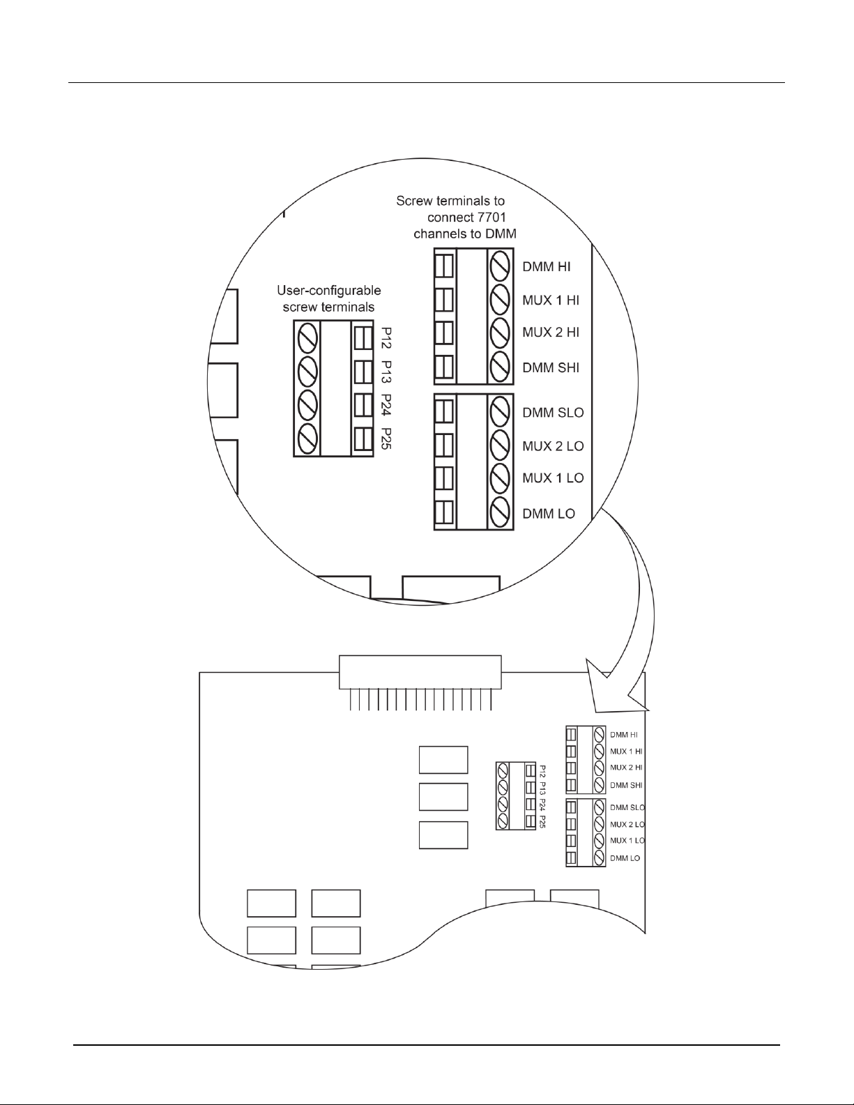
The screw terminals of the 7701 are shown in the following figure. Screw terminals are provided to connect the
switching module channels to the instrument. User-configurable screw terminals allow the external input to
bypass the switching module channels.
Four jumpers are supplied with the 7701 for use with the screw terminals. As shipped, the jumpers are not
installed in the 7701, as shown in the following figure. When the jumpers are not installed, all input to the 7701
is electrically isolated from the DMM.
Equipment needed:
▪ Flat-blade screwdriver
▪ Cable ties
To make connections to the 7701:
1. Make sure all power is discharged from the 7701 module.
2. Using a screwdriver, turn the access screw to unlock and open the cover.
3. Using the flat-blade screwdriver, loosen the terminal screws and install the wires as needed. The channel
designations for the screw terminals are shown in the following figures.
077144700 / June 2018
Page 3
Model 7701 Multiplexer Module Instructions for use with DAQ6510
3
Figure 2: 7701 screw terminals
077144700 / June 2018
Page 4

Model 7701 Multiplexer Module Instructions for use with DAQ6510
4
4. Install the four supplied #22 AWG jumpers in the screw terminals as shown in the following figure. Position
the jumpers to allow clearance for the top cover. Make sure the jumper wires do not contact each other or
other electrical conductors.
▪ Jumper A: Connects the HI terminals of the multiplexer 1 channels (1 to 16) to the DMM Input HI.
▪ Jumper B: Connects the HI terminals of the multiplexer 2 channels (17 to 32) to the DMM Sense HI.
▪ Jumper C: Connects the LO terminals of the multiplexer 2 channels (17 to 32) to the DMM Sense LO.
▪ Jumper D: Connects the LO terminals of the multiplexer 1 channels (1 to 16) to the DMM Input LO.
Figure 3: Jumper installation to connect 7701 channels to DMM
5. Use a flat-blade screwdriver to replace the top cover.
D-sub connectors
The following figure shows the pin numbers for the 7701 rear-panel connectors. The 50-pin D-sub is used to
access channels 1 to 24 and Multiplexer 1 terminals. The 25-pin D-sub is used to access channels 25 to 32 and
Multiplexer 2 terminals. The user-configurable screw terminals are also accessed at the 25-pin D-sub. Terminal
identification for the socket connector pins is provided in the following tables.
Figure 4: 7701 pinouts – rear view
077144700 / June 2018
Page 5

Model 7701 Multiplexer Module Instructions for use with DAQ6510
5
50-pin D-sub connector
Pin
7701
Terminal
Pin
7701
Terminal
Pin
7701
Terminal
Pin
7701
Terminal
Pin
7701
Terminal
1
Ch 1 Hi
11
Ch 16 Hi
21
Ch 6 Lo
31
Ch 21 Lo
41
Ch 12 Hi
2
Ch 2 Lo
12
Ch 17 Lo
22
Ch 8 Hi
32
Ch 23 Hi
42
Ch 13 Lo
3
Ch 4 Hi
13
Ch 19 Hi
23
Ch 9 Lo
33
Ch 24 Lo
43
Ch 15 Hi
4
Ch 5 Lo
14
Ch 20 Lo
24
Ch 11 Hi
34
Ch 1 Lo
44
Ch 16 Lo
5
Ch 7 Hi
15
Ch 22 Hi
25
Ch 12 Lo
35
Ch 3 Hi
45
Ch 18 Hi
6
Ch 8 Lo
16
Ch 23 Lo
26
Ch 14 Hi
36
Ch 4 Lo
46
Ch 19 Lo
7
Ch 10 Hi
17
MUX 1 Hi
27
Ch 15 Lo
37
Ch 6 Hi
47
Ch 21 Hi
8
Ch 11 Lo
18
Ch 2 Hi
28
Ch 17 Hi
38
Ch 7 Lo
48
Ch 22 Lo
9
Ch 13 Hi
19
Ch 3 Lo
29
Ch 18 Lo
39
Ch 9 Hi
49
Ch 24 Hi
10
Ch 14 Lo
20
Ch 5 Hi
30
Ch 20 Hi
40
Ch 10 Lo
50
MUX 1 Lo
077144700 / June 2018
Page 6

Model 7701 Multiplexer Module Instructions for use with DAQ6510
6
25-pin D-sub connector
Pin
7701
Terminal
Pin
7701
Terminal
Pin
7701
Terminal
Pin
7701
Terminal
1
Ch 25 Hi
7
Ch 31 Hi
14
Ch 25 Lo
20
Ch 31 Lo
2
Ch 26 Hi
8
Ch 32 Hi
15
Ch 26 Lo
21
Ch 32 Lo
3
Ch 27 Hi
9
MUX 2 Hi
16
Ch 27 Lo
22
MUX 2 Lo
4
Ch 28 Hi
10,
11
Not connected
17
Ch 28 Lo
23
Not connected
5
Ch 29 Hi
12
P12
18
Ch 29 Lo
24
P24
6
Ch 30 Hi
13
P13
19
Ch 30 Lo
25
P25
Wiring
You must install a connector cover on an unused D-sub connector. If the connector is left
open, an electrical shock hazard may be present. Failure to recognize and observe normal
safety precautions could result in personal injury or death.
The 7701 is supplied with one 50-pin IDC ribbon cable connector and one 25-pin IDC ribbon cable connector.
These ribbon cable connectors connect to the D-sub connectors of the switching module.
When using IDC ribbon cable connections, do not exceed 42 V anywhere in the test system or
at the front-panel inputs of the DAQ6510. For higher voltage applications, use larger wire (up
to #20 AWG) and solder cup D-sub connectors. Failure to recognize and observe normal
safety precautions could result in personal injury or death.
There are two connector kits that have connectors that can be used with the Model 7701:
▪ Model 7790 ribbon cable adapter kit: Contains one DB-50 socket, one DB-50 plug, and one DB-25
ribbon cable plug.
▪ Model 7789 50/25-pin solder cup connector kit: Contains one DB-50 connector and one DB-25 solder
cup connector.
077144700 / June 2018
Page 7

Model 7701 Multiplexer Module Instructions for use with DAQ6510
7
Ribbon Cable*:
7701
DB-50
Ribbon Cable*:
7701
DB-50
Conductor
Color
Terminal
Pin #
Conductor
Color
Terminal
Pin #
1
Brown
Ch 1 Hi
1
26
Blue
Ch 13 Lo
42
2
Red
Ch 1 Lo
34
27
Violet
Ch 14 Hi
26 3 Orange
Ch 2 Hi
18
28
Gray
Ch 14 Lo
10
4
Yellow
Ch 2 Lo
2
29
White
Ch 15 Hi
43 5 Green
Ch 3 Hi
35
30
Black
Ch 15 Lo
27 6 Blue
Ch 3 Lo
19
31
Brown
Ch 16 Hi
11
7
Violet
Ch 4 Hi
3
32
Red
Ch 16 Lo
44 8 Gray
Ch 4 Lo
36
33
Orange
Ch 17 Hi
28 9 White
Ch 5 Hi
20
34
Yellow
Ch 17 Lo
12
10
Black
Ch 5 Lo
4
35
Green
Ch 18 Hi
45
11
Brown
Ch 6 Hi
37
36
Blue
Ch 18 Lo
29
12
Red
Ch 6 Lo
21
37
Violet
Ch 19 Hi
13
13
Orange
Ch 7 Hi
5
38
Gray
Ch 19 Lo
46
14
Yellow
Ch 7 Lo
38
39
White
Ch 20 Hi
30
15
Green
Ch 8 Hi
22
40
Black
Ch 20 Lo
14
16
Blue
Ch 8 Lo
6
41
Brown
Ch 21 Hi
47
17
Violet
Ch 9 Hi
39
42
Red
Ch 21 Lo
31
18
Gray
Ch 9 Lo
23
43
Orange
Ch 22 Hi
15
19
White
Ch 10 Hi
7
44
Yellow
Ch 22 Lo
48
20
Black
Ch 10 Lo
40
45
Green
Ch 23 Hi
32
21
Brown
Ch 11 Hi
24
46
Blue
Ch 23 Lo
16
22
Red
Ch 11 Lo
8
47
Violet
Ch 24 Hi
49
23
Orange
Ch 12 Hi
41
48
Gray
Ch 24 Lo
33
24
Yellow
Ch 12 Lo
25
49
White
MUX 1 Hi
17
25
Green
Ch 13 Hi
9
50
Black
MUX 1 Lo
50
* 50-conductor IDC ribbon cable is available from Keithley Instruments. Reference part #15020. You
need a 50-conductor flat ribbon cable with 26 AWG wire on 0.050-inch centers rated at 50 V or greater.
IDC ribbon cable connections
Connect an appropriate length of 50-conductor IDC ribbon cable to a 50-pin plug D-sub IDC connector, and
connect an appropriate length of 25-conductor IDC ribbon cable to a 25-pin plug D-sub IDC connector. The
following table and figure provide terminal identification for the 50-pin ribbon cable connections.
Terminal identification for 50-conductor IDC ribbon cable and 7701 DB-50 connector
077144700 / June 2018
Page 8
Model 7701 Multiplexer Module Instructions for use with DAQ6510
8
Ribbon Cable*:
7701
DB-25
Ribbon Cable*:
7701
DB-25
Conductor
Color
Terminal
Pin #
Conductor
Color
Terminal
Pin #
1
Brown
Ch 25 Hi
1
14
Yellow
Ch 31 Lo
20
2
Red
Ch 25 Lo
14
15
Green
Ch 32 Hi
8 3 Orange
Ch 26 Hi
2
16
Blue
Ch 32 Lo
21 4 Yellow
Ch 26 Lo
15
17
Violet
MUX 2 Hi
9
5
Green
Ch 27 Hi
3
18
Gray
MUX 2 Lo
22 6 Blue
Ch 27 Lo
16
19
White
Not connected
10 7 Violet
Ch 28 Hi
4
20
Black
Not connected
23
8
Gray
Ch 28 Lo
17
21
Brown
Not connected
11
9
White
Ch 29 Hi
5
22
Red
P24
24
10
Black
Ch 29 Lo
18
23
Orange
P12
12
11
Brown
Ch 30 Hi
6
24
Yellow
P25
25
12
Red
Ch 30 Lo
19
25
Green
P13
13
13
Orange
Ch 31 Hi
7
* 25-conductor IDC ribbon cable is available from Keithley Instruments. Reference part #15025. You need a
25-conductor flat ribbon cable with 28 AWG wire on 0.050-inch centers at 50 V or greater.
The following table and figure provide terminal identification for the 25-pin ribbon cable connections.
Terminal identification for 25-conductor IDC ribbon cable and 7701 DB-25 connector
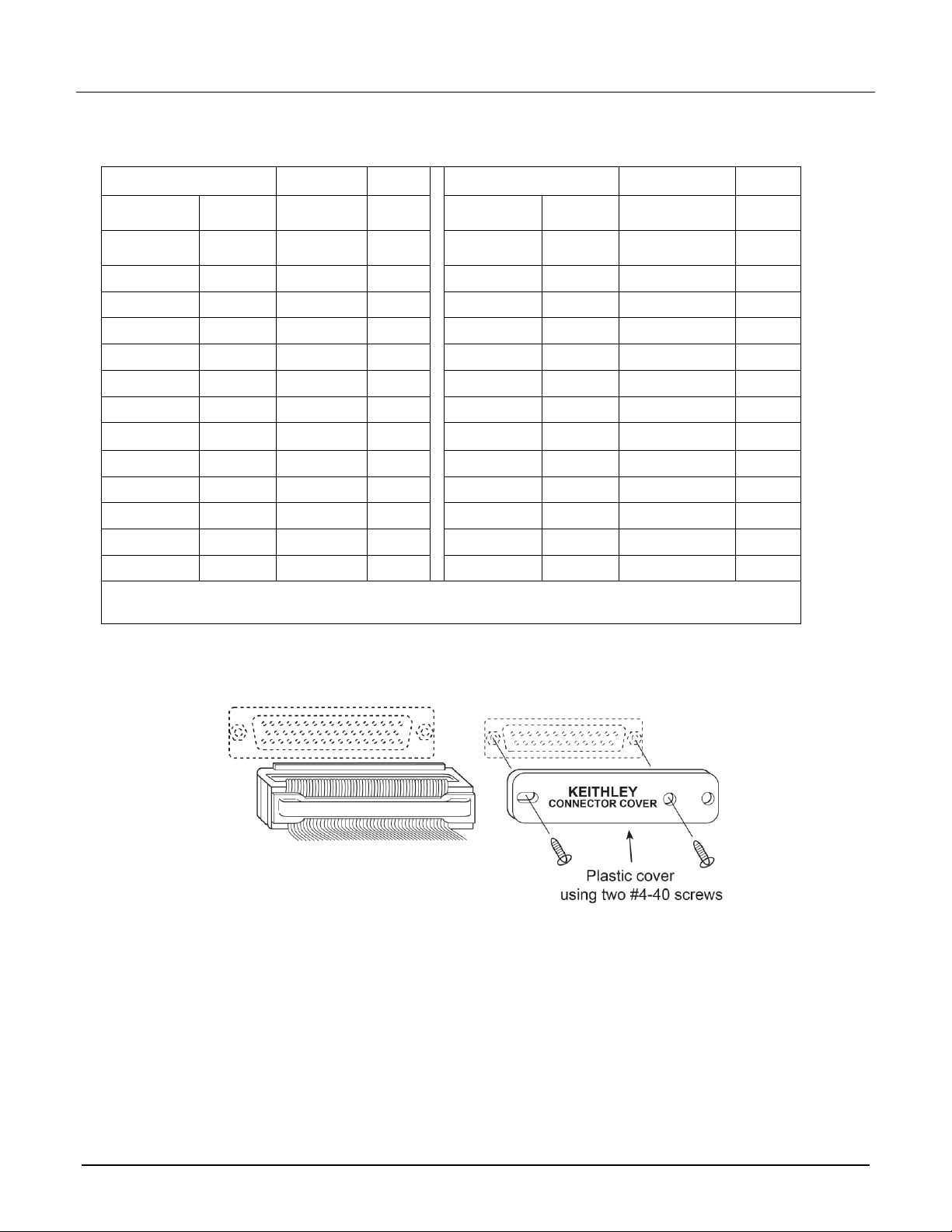
The connectors of the prepared ribbon cable assemblies mate to the 50- and 25-pin D-sub connectors of the
7701. If a D-sub connector is unused, make sure the connector cover installed. See the following figure.
Figure 5: Connecting ribbon cable assembly
077144700 / June 2018
Page 9
Model 7701 Multiplexer Module Instructions for use with DAQ6510
9
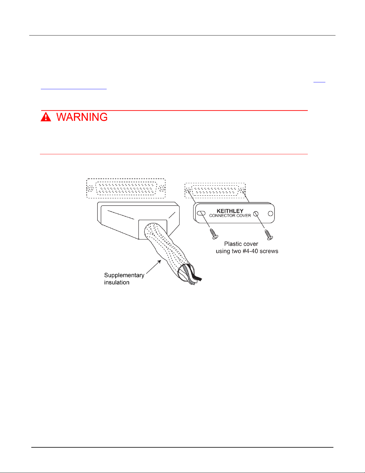
7789 Solder Cup Adapter Kit cable connections
Make all connections to D-sub plug solder cup connectors using the correct wire size up to 20 AWG. Terminal
identification for the 50-pin D-sub connector and the 25-pin D-sub connector is provided in the tables in IDC
ribbon cable connections (on page 7). Add supplementary insulation around the harness for voltages above 42
V
, as shown in the following figure.
PEAK
If a D-sub connector is unused, make sure the connector cover is installed as shown in the following figure.
All solder cup wiring must be rated for the maximum voltage in the system. For example, if
150 V is applied to the front terminals of the instrument, all matrix module wiring must be
rated for 150 V. Failure to recognize and observe normal safety precautions could result in
personal injury or death.
Figure 6: Connecting solder cup cable assembly
077144700 / June 2018
Page 10

Model 7701 Multiplexer Module Instructions for use with DAQ6510
10
Typical connections
The following examples show typical wiring connections for the following types of measurements:
▪ Two-wire resistance and thermistor
▪ Four-wire resistance and RTD
▪ DC or AC voltage
Figure 7: 2-wire resistance and thermistor connections
Figure 8: 4-wire resistance and RTD connections
077144700 / June 2018
Page 11

11
Connection log
Model 7701 Multiplexer Module Instructions for use with DAQ6510
Figure 9: Voltage connections - DC or AC
You can use the next table to record your connection information.
077144700 / June 2018
Page 12

Model 7701 Multiplexer Module Instructions for use with DAQ6510
12
Channel
Color
Description
Description
Color
Channel
MUX 1
H
P12 L P13
MUX 2
H
P24 L P25
CH1
H
H
CH17
L
L
CH2
H
H
CH18
L
L
CH3
H
H
CH19
L
L
CH4
H
H
CH20
L
L
CH5
H
H
CH21
L
L
CH6
H
H
CH22
L
L
CH7
H
H
CH23
L
L
CH8
H
H
CH24
L
L
CH9
H
H
CH25
L
L
CH10
H
H
CH26
L
L
CH11
H
H
CH27
L
L
CH12
H
H
CH28
L
L
CH13
H
H
CH29
L
L
CH14
H
H
CH30
L
L
CH15
H
H
CH31
L
L
CH16
H
H
CH32
L
L
Connection log for the 7701
077144700 / June 2018
Page 13
Model 7701 Multiplexer Module Instructions for use with DAQ6510
13
Installation
Before operating an instrument with a switching module, verify that the switching module is
properly installed and the mounting screws are tightly fastened. If the mounting screws are
not properly connected, an electrical shock hazard may be present.
If you are installing two switching modules, it is easier to install one switching module into slot 2 first, then install
the second switching module into slot 1.
If you have a Keithley Instruments Model 2700, 2701, or 2750 instrument, you can use your existing
switching module in the DAQ6510. Follow the instructions in your original equipment documentation
to remove the module from the instrument, then use the following instructions to install it in the
DAQ6510. You do not need to remove wiring to the module.
For inexperienced users, it is recommended that you do not connect a device under test (DUT) and
external circuitry to the switching module. This allows you to exercise close and open operations
without the dangers associated with live test circuits. You can also set up pseudocards to experiment
with switching. Refer to "Pseudocards" in the Model DAQ6510 Data Acquisition and Multimeter
System Reference Manual for information on setting up pseudocards.
To prevent electric shock that could result in injury or death, never handle a switching
module that has power applied to it. Before installing or removing a switching module, make
sure the DAQ6510 is turned off and disconnected from line power. If the switching module is
connected to a DUT, make sure power is removed from all external circuitry.
If a card slot is unused, you must install slot covers to prevent personal contact with high
voltage circuits. Failure to install slot covers could result in personal exposure to hazardous
voltages, which could cause personal injury or death if contacted.
Before installing or removing a switching module, make sure the DAQ6510 power is turned
off and disconnected from line power. Failure to comply may result in incorrect operation and
loss of data in the memory.
Required equipment:
▪ Medium flat-blade screwdriver
▪ Medium Phillips screwdriver
077144700 / June 2018
Page 14

Model 7701 Multiplexer Module Instructions for use with DAQ6510
14
To install a switching module into the DAQ6510:
1. Turn off the DAQ6510.
2. Disconnect the power cord from the power source.
3. Disconnect the power cord and any other cables that are connected to the rear panel.
4. Position the DAQ6510 so you are facing the rear panel.
5. Use the screwdriver to remove the slot cover screws and the cover plate. Retain the plate and screws for
future use.
6. With the top cover of the switching module facing up, slide the switching module into the slot.
7. Press the switching module in firmly to make sure the switching module connector is connected to the
DAQ6510 connector.
8. Use the screwdriver to tighten the two mounting screws to secure the switching module to the mainframe.
Do not overtighten.
9. Reconnect the power cord and any other cables.
Remove a switching module
Before you remove a switching module or begin any testing, make sure that all the relays are open.
Since some relays may be latched closed, you must open all the relays before removing the
switching module to make connections. Additionally, if you drop your switching module, it is possible
for some relays to latch closed.
To open all channel relays, go to the CHANNEL swipe screen. Select Open All.
To prevent electric shock that could result in injury or death, never handle a switching
module that has power applied to it. Before installing or removing a switching module, make
sure the DAQ6510 is turned off and disconnected from line power. If the switching module is
connected to a DUT, make sure power is removed from all external circuitry.
If a card slot is unused, you must install slot covers to prevent personal contact with high
voltage circuits. Failure to install slot covers could result in personal exposure to hazardous
voltages, which could cause personal injury or death if contacted.
077144700 / June 2018
Page 15

Model 7701 Multiplexer Module Instructions for use with DAQ6510
15
Before installing or removing a switching module, make sure the DAQ6510 power is turned
off and disconnected from line power. Failure to comply may result in incorrect operation and
loss of data in the memory.
Required equipment:
▪ Medium flat-blade screwdriver
▪ Medium Phillips screwdriver
To remove a switching module from the DAQ6510:
1. Turn off the DAQ6510.
2. Disconnect the power cord from the power source.
3. Disconnect the power cord and any other cables that are connected to the rear panel.
4. Position the DAQ6510 so you are facing the rear panel.
5. Use the screwdriver to loosen the mounting screws that secure the switching module to the instrument.
6. Carefully remove the switching module.
7. Install a slot plate or another switching module in the empty slot.
8. Reconnect the power cord and any other cables.
Operation
Refer to the instrument documentation for operating instructions.
This switching module does not support current measurements. If the instrument has the TERMINALS switch
set to REAR and you are working with the slot that contains this switching module, the AC, DC, and digitize
current functions are not available. You can measure current using the front panel or using another slot that
contains a switching module that supports the AC, DC, and digitize current measurements.
If you use remote commands to attempt to measure current when configuring a channel, an error is returned.
077144700 / June 2018
Page 16

Model 7701 Multiplexer Module Instructions for use with DAQ6510
16
Module configuration schematic
The following figure shows a simplified schematic diagram of the 7701 module. The 7701 has input channels
that are grouped into two banks of 16 channels (32 channels total). A backplane isolation relay is provided for
each bank. The first bank contains channels 1 to 16 while the second bank contains channels 17 to 32. Each
input channel of the 32-channel multiplexer module is wired with separate inputs for HI/LO, providing fully
isolated inputs.
As shown in the following figure, all 7701 channels are isolated from the DMM of the DAQ6510 by screw
terminals. To connect the switching module channels to the DMM, you must install the supplied jumpers, as
described in Screw terminals (on page 2).
For added flexibility, the 7701 is equipped with four extra screw terminals. These user-configurable screw
terminals are hard-wired to the DB-25 socket connector of the switching module. These screw terminals allow
you to use an external input to bypass the switching module channels.
Although the 7701 relays are the latching type (relays hold their state even after power has been removed), all
relay states are set to open a few seconds after either a power cycle or a reset command is issued.
With a 2-wire function selected (such as DCV), channels 1 to 32 can be closed. When one of these channels is
closed, channel 35 automatically closes to connect the channel to the DMM Input.
With a normal 4-wire function selected (such as 4-wire resistance), channels 1 to 16 can be closed. These 16
channels are paired to channels 17 to 32 (channel 1 paired to channel 17, channel 2 paired to channel 18, and
so on). When one of these system channels is closed, its paired channel and channels 33 and 34 also close to
connect the DUT to the DMM.
077144700 / June 2018
Page 17

Model 7701 Multiplexer Module Instructions for use with DAQ6510
17
Figure 10: 7701 simplified schematic
The 7701 is rated for low-voltage applications. When connecting the 7701 to the internal DMM using
the screw terminals, all other modules in the mainframe must be derated to 150 VDC or 150 V
(212 V
) for AC waveforms.
PEAK
Channels 33 to 35 in this schematic refer to designations used for control and are not available
channels.
077144700 / June 2018
RMS
Page 18

Model 7701 Multiplexer Module Instructions for use with DAQ6510
18
Tested
Device
Closed
Channels
Tested
Device
Closed
Channels
Tested
Device
Closed
Channels
Tested
Device
Closed
Channels
DUT 1
1 and 35
DUT 9
9 and 35
DUT 17
17 and 35
DUT 25
25 and 35
DUT 2
2 and 35
DUT 10
10 and 35
DUT 18
18 and 35
DUT 26
26 and 35
DUT 3
3 and 35
DUT 11
11 and 35
DUT 19
19 and 35
DUT 27
27 and 35
DUT 4
4 and 35
DUT 12
12 and 35
DUT 20
20 and 35
DUT 28
28 and 35
DUT 5
5 and 35
DUT 13
13 and 35
DUT 21
21 and 35
DUT 29
29 and 35
DUT 6
6 and 35
DUT 14
14 and 35
DUT 22
22 and 35
DUT 30
30 and 35
DUT 7
7 and 35
DUT 15
15 and 35
DUT 23
23 and 35
DUT 31
31 and 35
DUT 8
8 and 35
DUT 16
16 and 35
DUT 24
24 and 35
DUT 32
32 and 35
Channels 33, 34, and 35 can be individually controlled. For more information, refer to "Multiple
channel operation" in the instrument reference manual.
Applications
The following applications use multiple channel operation, where each channel is controlled
independently. Multiple channel operation should only be performed by experienced test
engineers who recognize the dangers associated with multiple channel closures. Failure to
recognize and observe normal safety precautions could result in personal injury or death.
Refer to "Multiple channel operation" in the instrument reference manual for additional information.
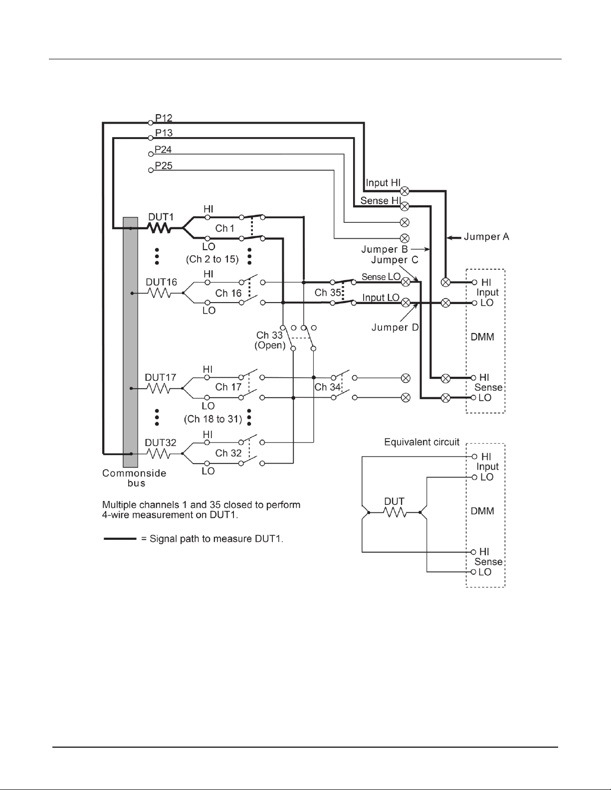
Commonside 4-wire resistance measurements
When using 4-wire resistance measurements and normal channel operation, the instrument can test up to 16
DUTs. By using multiple channel operation and the user-configurable screw terminals, the instrument can test
up to 32 DUTs using 4-wire resistance. An example of this test system is shown in the figure following the table.
All 32 DUTs are connected to a common metal bus. The bus is connected directly to Input HI and Sense HI of
the DMM through the user-configurable screw terminals. The 32 measurement channels can be used to
connect the other side of each DUT to Input LO and Sense LO of the DMM.
For this application, control channels 33 and 35 as follows:
▪ Opening channel 33 connects Multiplexer 1 (channels 1 to 16) to Multiplexer 2 (channels 17 to 32).
Channel 33 must remain open for all DUT tests.
▪ Closing channel 35 connects a measurement channel (1 to 32) to the DMM Input. Channel 35 must
remain closed for all DUT tests.
In the figure following the table, channels 1 and 35 are closed to test DUT 1. The tests for the other DUTs are
similar except that different measurement channels are closed, as shown in the following table.
In the figure below, the bold lines show the signal path to test DUT 1.
077144700 / June 2018
Page 19
Model 7701 Multiplexer Module Instructions for use with DAQ6510
19
Figure 11: Commonside 4-wire test system (multiple-channel operation)
077144700 / June 2018
Page 20
Model 7701 Multiplexer Module Instructions for use with DAQ6510
20
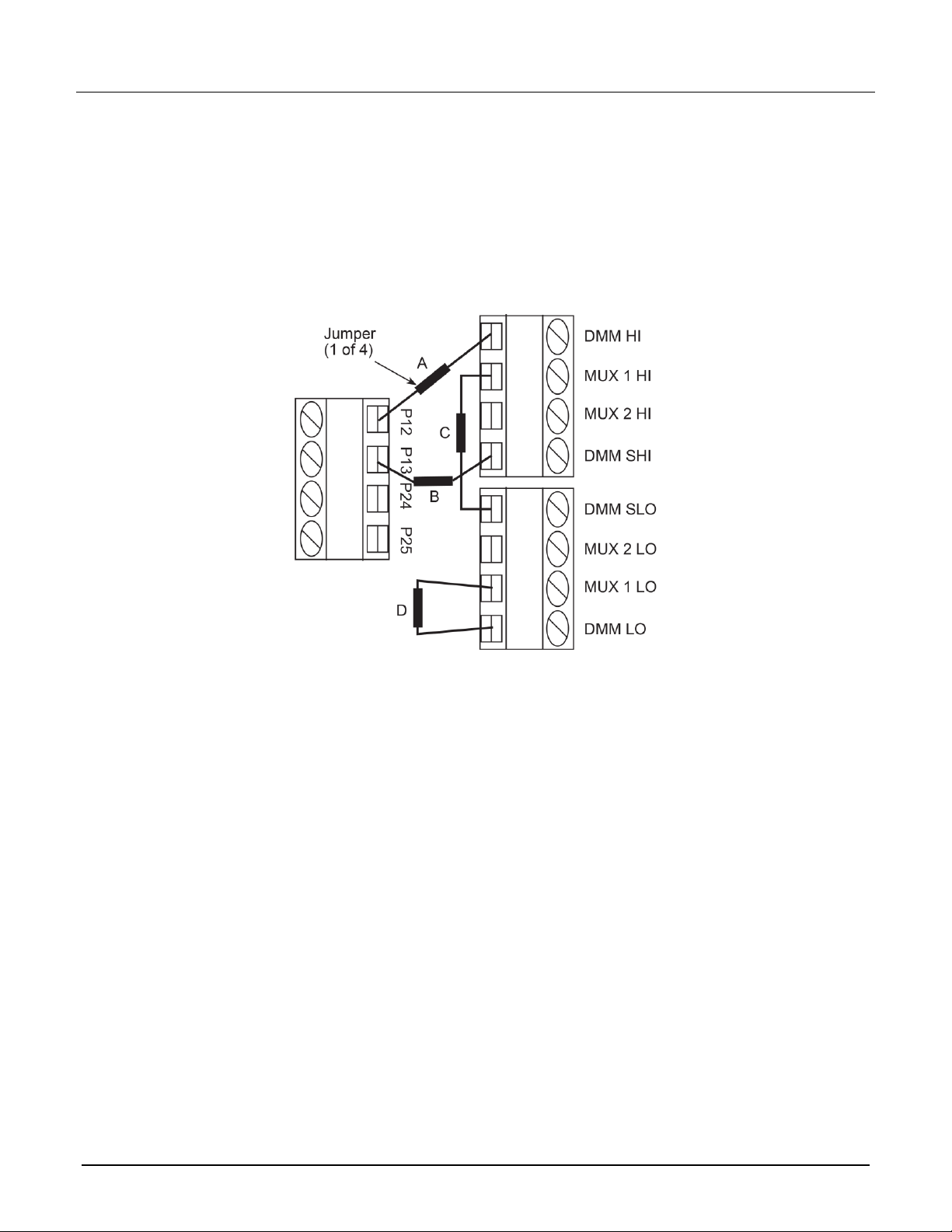
Jumper installation for 4-wire commonside ohms application
Jumper installation for the commonside 4-wire resistance test system is shown in the following figure.
In the following figure:
▪ Jumper A: Connects the DUT commonside bus (P12) to DMM Input HI.
▪ Jumper B: Connects the DUT commonside bus (P13) to DMM Sense HI.
▪ Jumper C: Connects the DUT to DMM Sense LO through the switching channels.
▪ Jumper D: Connects the DUT to DMM Input LO through the switching channels.
Figure 12: Jumper installation for commonside 4-wire resistance test system
Test setup
On the front panel of the DAQ6510, set TERMINALS to REAR for this test.
Test procedure
You must run this application using remote commands with the switching module in slot 1.
The following example shows how to remotely configure for commonside ohms, then sequentially make
measurements on DUTs 1 to 32 (as shown in the figure above). Repeat these steps for the channel
sequentially for each DUT (2 to 32). The example then demonstrates how to returns the data from the reading
buffer and open all channels.
Using SCPI commands
ROUTe:OPEN:ALL
SENSe:FUNCtion "FRESistance", (@101:132)
ROUTe:CSOhms (@slot1), ON
ROUTe:CLOSe (@101)
READ?
Repeat closing and reading channels for each DUT (channels 102 to 131).
ROUTe:CLOSe (@132)
READ?
TRACe:DATA? 1, 32, "defbuffer1"
ROUTe:OPEN:ALL
077144700 / June 2018
Page 21
Model 7701 Multiplexer Module Instructions for use with DAQ6510
21
Using TSP commands
channel.open("allslots")
channel.setdmm("slot1", dmm.ATTR_MEAS_FUNCTION, dmm.FUNC_4W_RESISTANCE)
channel.setcommonside("slot1", channel.ON)
channel.close("101")
print(dmm.measure.read())
Repeat closing and reading channels for each DUT (channels 102 to 131).
channel.close("132")
print(dmm.measure.read())
printbuffer(1, defbuffer1.n, defbuffer1)
channel.open("allslots")
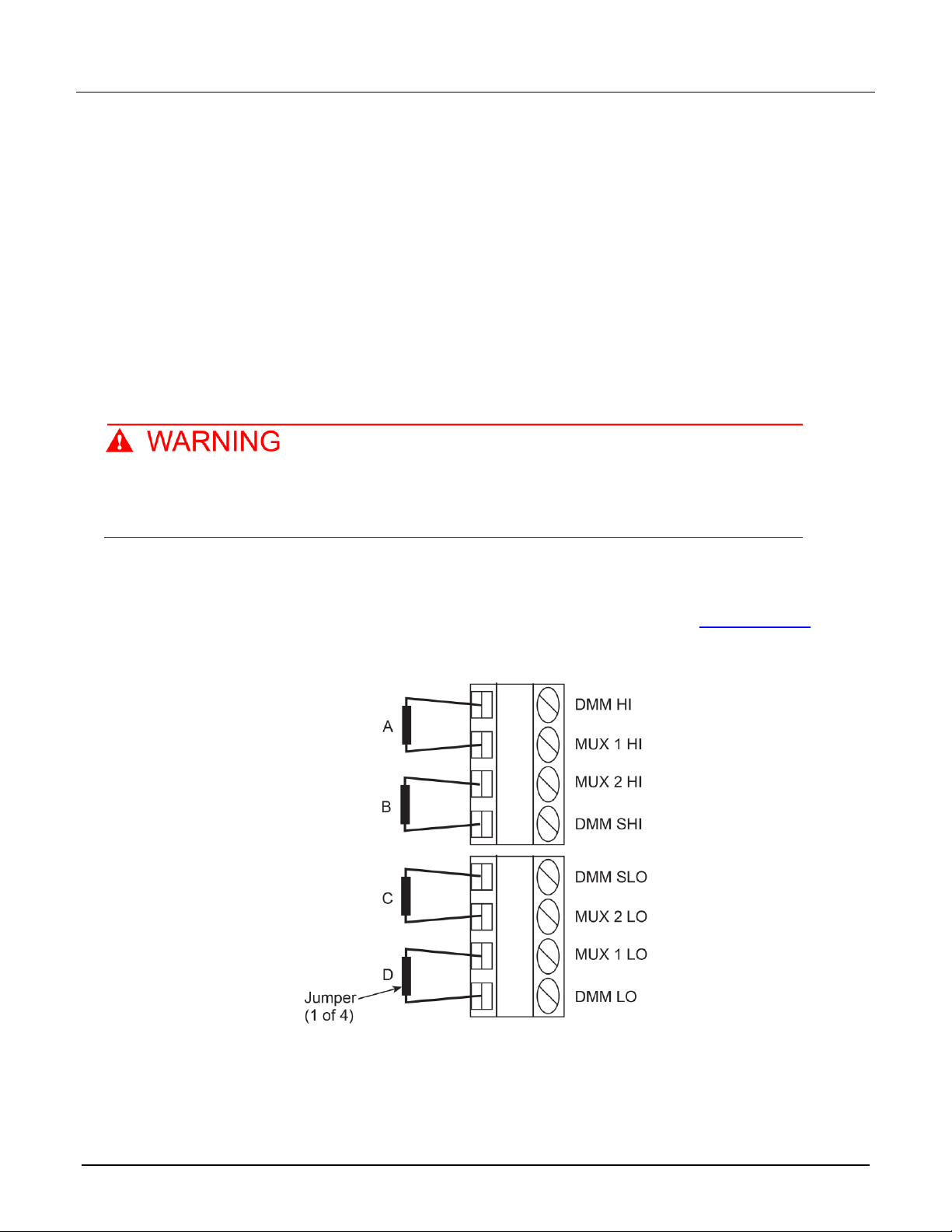
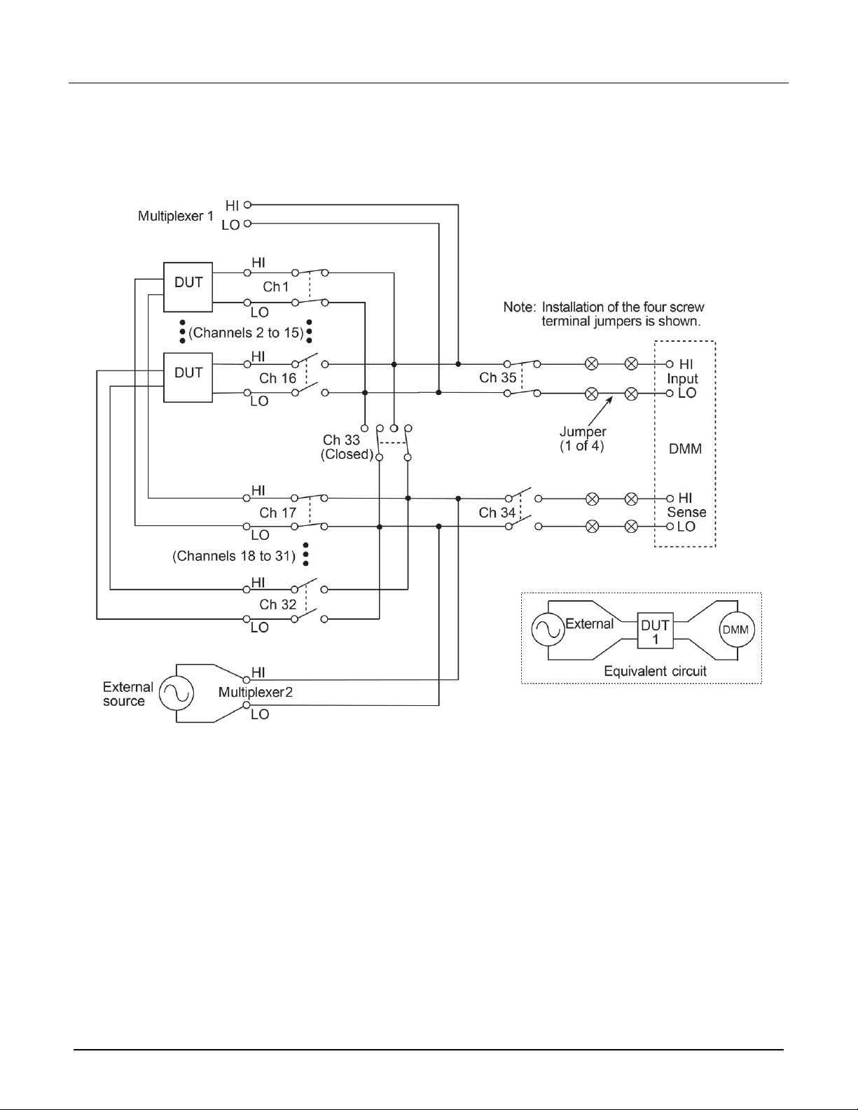
Biasing and measuring DUTs (dual multiplexing)
Multiple channel operation is required for the following application. Multiple channel
operation should only be performed by experienced test engineers who recognize the
dangers associated with multiple channel closures. Failure to recognize and observe normal
safety precautions could result in personal injury or death.
This application demonstrates how to use the 7701 as a dual multiplexer to bias and measure 16 DUTs. An
external source powers the DUT, while the DMM of the DAQ6510 measures the output of the DUT. To prevent
overloading of the external source, each DUT is powered and measured separately.
For this application, the jumpers must be set as shown in the following figure. Refer to Screw terminals (on
page 2) for more information on setting the jumpers.
Figure 13: Jumper installation to connect 7701 channels to DMM
077144700 / June 2018
Page 22

Model 7701 Multiplexer Module Instructions for use with DAQ6510
22
Tested
Device
Closed
Channels
Tested
Device
Closed
Channels
DUT 1
1, 17, 33, and 35
DUT 9
9, 25, 33, and 35
DUT 2
2, 18, 33, and 35
DUT 10
10, 26, 33, and 35
DUT 3
3, 19, 33, and 35
DUT 11
11, 27, 33, and 35
DUT 4
4, 20, 33, and 35
DUT 12
12, 28, 33, and 35
DUT 5
5, 21, 33, and 35
DUT 13
13, 29, 33, and 35
DUT 6
6, 22, 33, and 35
DUT 14
14, 30, 33, and 35
DUT 7
7, 23, 33, and 35
DUT 15
15, 31, 33, and 35
DUT 8
8, 24, 33, and 35
DUT 16
16, 32, 33, and 35
The figure after the table shows the connections for this application. The external source is connected to the
Multiplexer 2 terminals of the switching module, and a DUT is connected to channels 1 to 16. Channels 17 to
32 are used to connect external power to each DUT.
For this application, channels 33, 34, and 35 are controlled as follows:
▪ Closing channel 33 isolates the input measurement channels 1 to 16 (Multiplexer 1) from the external
source channels 17 to 20 (Multiplexer 2). It also connects the DUT to the external source. This channel
must remain closed while testing a DUT.
▪ Opening channel 34 isolates the external source from the backplane of the DAQ6510. This channel must
remain open while testing a DUT.
▪ Closing channel 35 connects an input channel (1 to 16) to the DMM. This channel must remain closed
while testing a DUT.
Closed channels for each DUT test are listed in the following table.
077144700 / June 2018
Page 23
Model 7701 Multiplexer Module Instructions for use with DAQ6510
23
In the following figure, channels 1 and 17 are closed to test DUT 1. The test for the other DUTs is similar except
that different source and measure channels are closed.
Figure 14: Biasing and measuring DUT test system
077144700 / June 2018
Page 24

Model 7701 Multiplexer Module Instructions for use with DAQ6510
24
Test setup
On the front panel of the DAQ6510, set TERMINALS to REAR for this test.
Test procedure
You must run this application using remote commands with the switching module in slot 1.
In this example, you:
▪ Open all channels.
▪ Close channel 133.
▪ Close channel 135.
▪ Close channel 101.
▪ Close channel 117.
Repeat these steps for the channel for sequentially for each DUT as shown in the previous table. After all tests
are complete, open all channels.
SCPI commands
ROUTe:OPEN:ALL
SENSe:FUNCtion "VOLTage:DC"
ROUTe:MULTiple:CLOSe (@133)
ROUTe:MULTiple:CLOSe (@135)
ROUTe:MULTiple:CLOSe (@101)
ROUTe:MULTiple:CLOSe (@117)
READ?
ROUTe:MULTiple:OPEN (@101, 117)
TSP commands
channel.open("allslots")
dmm.measure.func = dmm.FUNC_DC_VOLTAGE
-- Close channel 33 to isolate measure channels (1 to 16) from source channels (17 to
32).
channel.multiple.close("133")
--Close channel 35 to connect measure channels (1 to 16) to the DMM Input.
channel.multiple.close("135")
-- Close channel 1 to test DUT1.
channel.multiple.close("101")
--Close channel 17 to connect DUT 1 to the external source.
channel.multiple.close("117")
--Measure DUT1
print(dmm.measure.read())
-- Open channel 1 and 17 to disconnect DUT1 from the DMM.
channel.multiple.open("101,117")
Factory service
To return the switching module to Keithley Instruments for repair:
▪ Call the Repair Department at 1-800-833-9200 or send an email to RMAREQUEST@tektronix.com for a
Return Material Authorization (RMA) number.
▪ Carefully pack the instrument in the original packing carton.
▪ Write ATTENTION REPAIR DEPARTMENT and the RMA number on the shipping label.
077144700 / June 2018
Page 25

25
Safety precautions
The following safety precautions should be observed before using this product and any associated instrumentation. Although
some instruments and accessories would normally be used with nonhazardous voltages, there are situations where hazardous
conditions may be present.
This product is intended for use by personnel who recognize shock hazards and are familiar with the safety precautions required
to avoid possible injury. Read and follow all installation, operation, and maintenance information carefully before using the
product. Refer to the user documentation for complete product specifications.
If the product is used in a manner not specified, the protection provided by the product warranty may be impaired.
The types of product users are:
Responsible body is the individual or group responsible for the use and maintenance of equipment, for ensuring that the
equipment is operated within its specifications and operating limits, and for ensuring that operators are adequately trained.
Operators use the product for its intended function. They must be trained in electrical safety procedures and proper use of the
instrument. They must be protected from electric shock and contact with hazardous live circuits.
Maintenance personnel perform routine procedures on the product to keep it operating properly, for example, setting the line
voltage or replacing consumable materials. Maintenance procedures are described in the user documentation. The procedures
explicitly state if the operator may perform them. Otherwise, they should be performed only by service personnel.
Service personnel are trained to work on live circuits, perform safe installations, and repair products. Only properly trained
service personnel may perform installation and service procedures.
Keithley products are designed for use with electrical signals that are measurement, control, and data I/O connections, with low
transient overvoltages, and must not be directly connected to mains voltage or to voltage sources with high transient
overvoltages. Measurement Category II (as referenced in IEC 60664) connections require protection for high transient
overvoltages often associated with local AC mains connections. Certain Keithley measuring instruments may be connected to
mains. These instruments will be marked as category II or higher.
Unless explicitly allowed in the specifications, operating manual, and instrument labels, do not connect any instrument to mains.
Exercise extreme caution when a shock hazard is present. Lethal voltage may be present on cable connector jacks or test
fixtures. The American National Standards Institute (ANSI) states that a shock hazard exists when voltage levels greater than
30 V RMS, 42.4 V peak, or 60 VDC are present. A good safety practice is to expect that hazardous voltage is present in any
unknown circuit before measuring.
Operators of this product must be protected from electric shock at all times. The responsible body must ensure that operators
are prevented access and/or insulated from every connection point. In some cases, connections must be exposed to potential
human contact. Product operators in these circumstances must be trained to protect themselves from the risk of electric shock. If
the circuit is capable of operating at or above 1000 V, no conductive part of the circuit may be exposed.
Do not connect switching cards directly to unlimited power circuits. They are intended to be used with impedance-limited
sources. NEVER connect switching cards directly to AC mains. When connecting sources to switching cards, install protective
devices to limit fault current and voltage to the card.
Before operating an instrument, ensure that the line cord is connected to a properly-grounded power receptacle. Inspect the
connecting cables, test leads, and jumpers for possible wear, cracks, or breaks before each use.
When installing equipment where access to the main power cord is restricted, such as rack mounting, a separate main input
power disconnect device must be provided in close proximity to the equipment and within easy reach of the operator.
For maximum safety, do not touch the product, test cables, or any other instruments while power is applied to the circuit under
test. ALWAYS remove power from the entire test system and discharge any capacitors before: connecting or disconnecting
cables or jumpers, installing or removing switching cards, or making internal changes, such as installing or removing jumpers.
Do not touch any object that could provide a current path to the common side of the circuit under test or power line (earth)
ground. Always make measurements with dry hands while standing on a dry, insulated surface capable of withstanding the
voltage being measured.
077144700 / June 2018
Page 26

26
For safety, instruments and accessories must be used in accordance with the operating instructions. If the instruments or
accessories are used in a manner not specified in the operating instructions, the protection provided by the equipment may be
impaired.
Do not exceed the maximum signal levels of the instruments and accessories. Maximum signal levels are defined in the
specifications and operating information and shown on the instrument panels, test fixture panels, and switching cards.
When fuses are used in a product, replace with the same type and rating for continued protection against fire hazard.
Chassis connections must only be used as shield connections for measuring circuits, NOT as protective earth (safety ground)
connections.
If you are using a test fixture, keep the lid closed while power is applied to the device under test. Safe operation requires the use
of a lid interlock.
If a screw is present, connect it to protective earth (safety ground) using the wire recommended in the user documentation.
The symbol on an instrument means caution, risk of hazard. The user must refer to the operating instructions located in the
user documentation in all cases where the symbol is marked on the instrument.
The symbol on an instrument means warning, risk of electric shock. Use standard safety precautions to avoid personal
contact with these voltages.
The symbol on an instrument shows that the surface may be hot. Avoid personal contact to prevent burns.
The symbol indicates a connection terminal to the equipment frame.
If this symbol is on a product, it indicates that mercury is present in the display lamp. Please note that the lamp must be
properly disposed of according to federal, state, and local laws.
The WARNING heading in the user documentation explains hazards that might result in personal injury or death. Always read
the associated information very carefully before performing the indicated procedure.
The CAUTION heading in the user documentation explains hazards that could damage the instrument. Such damage may
invalidate the warranty.
The CAUTION heading with the symbol in the user documentation explains hazards that could result in moderate or minor
injury or damage the instrument. Always read the associated information very carefully before performing the indicated
procedure. Damage to the instrument may invalidate the warranty.
Instrumentation and accessories shall not be connected to humans.
Before performing any maintenance, disconnect the line cord and all test cables.
To maintain protection from electric shock and fire, replacement components in mains circuits — including the power
transformer, test leads, and input jacks — must be purchased from Keithley. Standard fuses with applicable national safety
approvals may be used if the rating and type are the same. The detachable mains power cord provided with the instrument may
only be replaced with a similarly rated power cord. Other components that are not safety-related may be purchased from other
suppliers as long as they are equivalent to the original component (note that selected parts should be purchased only through
Keithley to maintain accuracy and functionality of the product). If you are unsure about the applicability of a replacement
component, call a Keithley office for information.
Unless otherwise noted in product-specific literature, Keithley instruments are designed to operate indoors only, in the following
environment: Altitude at or below 2,000 m (6,562 ft); temperature 0 °C to 50 °C (32 °F to 122 °F); and pollution degree 1 or 2.
To clean an instrument, use a cloth dampened with deionized water or mild, water-based cleaner. Clean the exterior of the
instrument only. Do not apply cleaner directly to the instrument or allow liquids to enter or spill on the instrument. Products that
consist of a circuit board with no case or chassis (e.g., a data acquisition board for installation into a computer) should never
require cleaning if handled according to instructions. If the board becomes contaminated and operation is affected, the board
should be returned to the factory for proper cleaning/servicing.
Safety precaution revision as of June 2017.
077144700 / June 2018
 Loading...