


Keithley Instruments
Model 7700 Multiplexer Module
28775 Aurora Road
Cleveland, Ohio 44139
1-800-935-5595
tek.com/keithley
Instructions for use with DAQ6510
Introduction
The 7700 20-Channel Differential Multiplexer Plug-In Module offers 20 channels of 2-pole or 10 channels of
4-pole multiplexer switching that can be configured as two independent banks of multiplexers. There are two
additional protected channels for current measurements. Automatic cold junction compensation (CJC) is
provided so that no other accessories are required to make thermocouple temperature measurements. In
addition, the 7700 contains latching electromechanical relays that enable signal bandwidths of up to 50 MHz.
The 7700 is ideal for RTD, thermistor, and thermocouple temperature applications.
Figure 1: 7700 20-Channel Differential Multiplexer Module
Item shipped may vary from model pictured here.
The 7700 includes the following features:
2-wire or 4-wire resistance measurements (automatically pairs switches for 4-wire measurements —
n + 10)
Screw terminal connections
Built-in cold junction reference
Latching type relays (relays hold their position after power is removed)
Two protected channels for current measurements (external shunts not required)
The 7700 can be used with the DAQ6510 Data Acquisition and Multimeter System.
If you are using this switching module with the 2700, 2701, or 2750, please see Model 7700, 7702,
and 7703 Multiplexer Modules Connection and Wiring Information, Keithley Instruments document
PA-695.
077144300 / April 2018 *077144300 * 1
Model 7700 Multiplexer Module Instructions for use with DAQ6510
Connections
Connection and wiring procedures in this document are intended for use by qualified
personnel only. Do not perform these procedures unless qualified to do so. Failure to
recognize and observe normal safety precautions could result in personal injury or death.
Do not exceed the maximum specifications for the 7700. Refer to the specifications provided
in the data sheet. Failure to recognize and observe normal safety precautions could result in
personal injury or death.
The following information describes how to make connections to the switching module and define the channel
designations. A log is provided that you can use to record your connections. See Connection log (on page 5
This section describes how to make connections to the terminal screws in the module. You can make:
Connections to DMM functions, which are provided through the module backplane connector
Current connections, provided through two protected channels (channels 21 and 22)
INPUT connections
SENSE (4-wire resistance) connections
AMP and LO common connections to the instrument
).
Wiring procedure
Use the following procedure to wire the 7700 module. Make all connections using the correct wire size (up to
20 AWG).
All wiring must be rated for the maximum voltage in the system. For example, if 1000 V is
applied to the front terminals of the instrument, the switching module wiring must be rated
for 1000 V. Failure to recognize and observe normal safety precautions could result in
personal injury or death.
2 077144300 / April 2018
Model 7700 Multiplexer Module Instructions for use with DAQ6510
Equipment needed:
Small flat-blade screwdriver
Cable ties
To make connections to the 7700 module:
1. Make sure all power is discharged from the 7700 module.
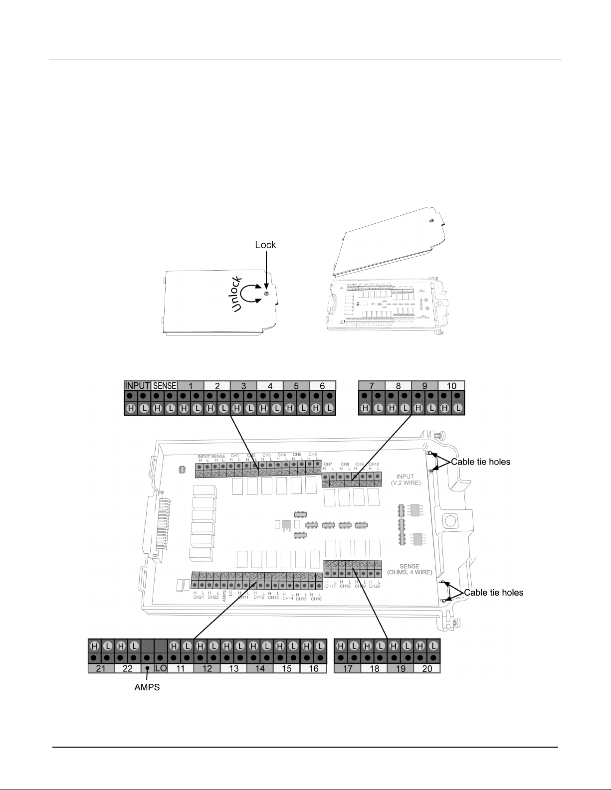
2. Use a screwdriver to turn the access screw to unlock and open the cover.
Figure 2: Screw terminal access
3. Use a small flat-blade screwdriver to loosen the terminal screws and install the wires as needed.
Figure 3: 7700 screw terminal channel designations
077144300 / April 2018 3
Model 7700 Multiplexer Module Instructions for use with DAQ6510
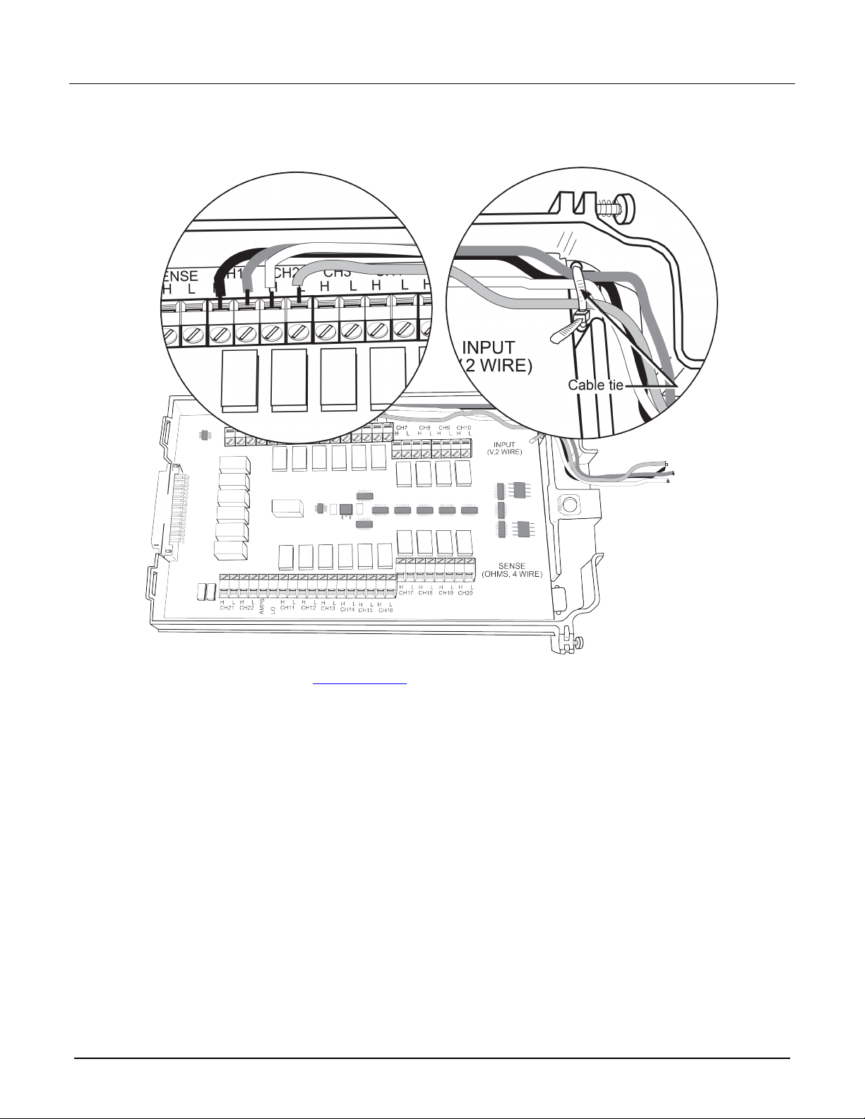
4. Route wire along the wire path and secure with cable tie as shown. The next figure also shows connections
to channels 1 and 2.
Figure 4: Wire dressing
5. Record the connections in the Connection log (on page 5).
6. Close the cover.
7. Use a screwdriver to press in the access screw and turn to lock the cover.
4 077144300 / April 2018

Model 7700 Multiplexer Module Instructions for use with DAQ6510
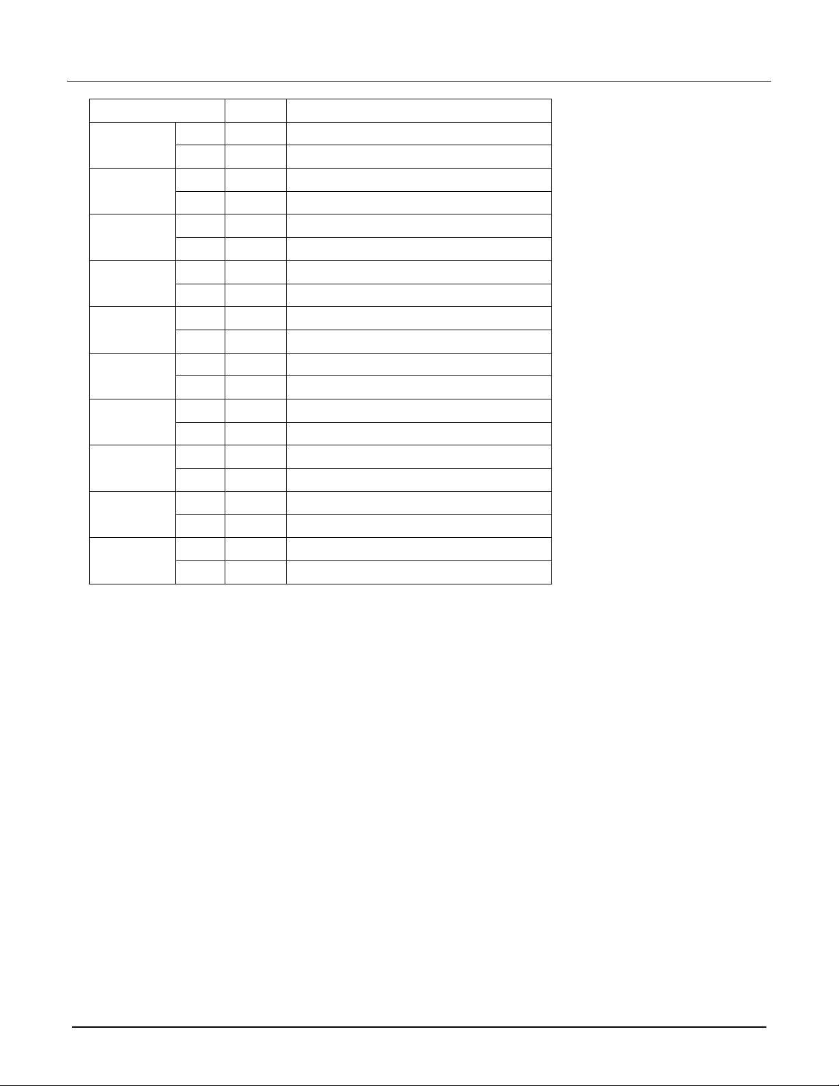
Connection log
You can use the next table to record your connection information.
Connection log for the 7700
Channel Color Description
AMPS COM H
L
INPUT H
L
SENSE H
L
CH1 H
L
CH2 H
L
CH3 H
L
CH4 H
L
CH5 H
L
CH6 H
L
CH7 H
L
CH8 H
L
CH9 H
L
CH10 H
L
CH11 H
L
CH12 H
L
077144300 / April 2018 5
Model 7700 Multiplexer Module Instructions for use with DAQ6510
Channel Color Description
CH13 H
L
CH14 H
L
CH15 H
L
CH16 H
L
CH17 H
L
CH18 H
L
CH19 H
L
CH20 H
L
AMPS21 H
L
AMPS22 H
L
6 077144300 / April 2018
Model 7700 Multiplexer Module Instructions for use with DAQ6510
Remove a switching module
Before you remove a switching module, or begin any testing, make sure that all of the relays are
open. Since some relays may be latched closed, you must open all of the relays before removing the
switching module to make connections. Additionally, if you drop your switching module, it is possible
for some relays to latch closed.
To open all channels select Menu > Control > Open. If there are no channels closed, the Open button is not
selectable.If any channel is closed, then the Open button is active and selecting it will open all channels.
To prevent electric shock that could result in injury or death, never handle a switching
module that has power applied to it. Before installing or removing a switching module, make
sure the DAQ6510 is turned off and disconnected from line power. If the switching module is
connected to a DUT, make sure power is removed from all external circuitry.
If a card slot is unused, you must install slot covers to prevent personal contact with high
voltage circuits. Failure to install slot covers could result in personal exposure to hazardous
voltages, which could cause personal injury or death if contacted.
Required equipment:
Medium flat blade screwdriver
Medium Phillips screwdriver
To remove switching module from the DAQ6510:
1. Turn off the DAQ6510.
2. Disconnect the power cord from the power source.
3. Disconnect the power cord and any other cables that are connected to the rear panel.
4. Position the DAQ6510 so you are facing the rear panel.
5. Use the screwdriver to loosen the mounting screws that secure the switching module to the mainframe.
6. Carefully remove the switching module.
7. Install a slot plate or switching module in the empty slot.
8. Reconnect the power cord and any other cables.
Installation
Before operating an instrument with an accessory switching module, verify that the switching
module is properly installed and the mounting screws are tightly fastened. If the mounting
screws are not properly connected, an electrical shock hazard may be present.
077144300 / April 2018 7
Model 7700 Multiplexer Module Instructions for use with DAQ6510
To use the switching operations, a switching module must be installed in the DAQ6510.
If you are installing two switching modules, it is easier to install one switching module into Slot 2 first, then
install the second switching module into Slot 1.
If you have a Keithley Instruments Model 2700, 2701, or 2750 instrument, you can use your existing
switching module in the DAQ6510. Follow the instructions in your original equipment documentation
to remove the module from the instrument, then use the following instructions to install it in the
DAQ6510. You do not need to remove wiring to the module.
For inexperienced users, it is recommended that you do not connect a device under test (DUT) and
external circuitry to the switching module. This allows you to exercise close and open operations
without the dangers associated with live test circuits. You can also set up pseudocards to experiment
with switching. Refer to Pseudocards in the Model DAQ6510 Reference Manual for information on
setting up pseudocards.
To prevent electric shock that could result in injury or death, never handle a switching
module that has power applied to it. Before installing or removing a switching module, make
sure the DAQ6510 is turned off and disconnected from line power. If the switching module is
connected to a DUT, make sure power is removed from all external circuitry.
If a card slot is unused, you must install slot covers to prevent personal contact with high
voltage circuits. Failure to install slot covers could result in personal exposure to hazardous
voltages, which could cause personal injury or death if contacted.
Required equipment:
Medium flat blade screwdriver
Medium Phillips screwdriver
To install switching module into the DAQ6510:
1. Turn off the DAQ6510.
2. Disconnect the power cord from the power source.
3. Disconnect the power cord and any other cables that are connected to the rear panel.
4. Position the DAQ6510 so you are facing the rear panel.
5. Use the screwdriver to remove the slot cover screws and the cover plate. Retain the plate and screws for
future use.
6. With the top cover of the switching module facing up, slide the switching module into the slot.
7. Press the switching module in firmly to make sure the switching module connector is connected to the
DAQ6510 connector.
8. Use the screwdriver to tighten the two mounting screws to secure the switching module to the mainframe.
Do not overtighten.
9. Reconnect the power cord and any other cables.
8 077144300 / April 2018
 Loading...