

Page 1
7313/R7313
I
OSCILLOSCOPE
MTM
OPTIDMS
OPERATORS
Page 2
Tektronix,
Inc.
P.O.
Box
500
Beaverton,
Oregon
97005
TH
OPT
IONS
OPERATORS
INSTRUCTION
MANUAL
Serial Number
First
Printing
JULY
1974
Page 3
WARRANTY
All
TEKTRONIX
instruments
are
warranted against
defective materials
and
workmanship
for
one
year.
Any
questions
with respect
to
the
warranty
should
'be
taken
up
with
your TEKTRONIX
Field
Engineer
or
representat'---
reques
..
rn
mm.
All
I
-par&
shouta
ne
alrecrea
ro
me
F
En
4
KUNIA
r~eld
Office
or
representative
in
your
area.
This
will assure
you
the
fastest
possible
service. Please include
the
instrument Type Number
or
Part Number
and Serial
Nu
ecif icatir
pyright
egon.
Pr
th
all rer
3ns and
1
quests
fc
rice
cha
by
Tek
the
Unitr
-+--*-
-4
~r
parts
lnge
privileges
reserved.
tmnix,
I
zd
State!
r..L
nc.,
Bee
;
of
Arne
ll*mb:*-.
rty11ia
reacr~ed.
COIIL~II~P
VI
11113
~UUIIC~~~IUII
IIIO~
11~1
be
reproduced
in
any
form
without
permission
of
Tektronix,
Inc.
U.S.A.
and
foreign
TEKf RONlX
products
covered
by
U.S.
and foreign
patents
and/or
patents
pending.
TEKTRON
Inc.
gistered
irk
of Tektronix,
Page 4
7313lR7313 Operators
TABLE OF CONTENTS
LlST OF ILLUSTRATIONS
LlST OF TABLES
SECTION 1 OPERATING INSTRUCTIONS
Preliminary Operation
Safety Information
Operating Voltage
Plug-In Units
Controls and Connectors
External
Internal
Familiarization Procedure
Set-Up Information
Display Controls
Vertical and Horizontal System Controls
Calibrator and Triggering Controls
Storage Controls
General Operating Information
Intensity Controls
Display Focus
Graticule
Beamfinder
Vertical Mode
Trigger Source
Readout (Deleted by Option
1)
Storage Operation
Calibrator
Signal Outputs
Remote Single Sweep Reset
(Delete with Option 7)
Display Photography
X-Y
Operation
Intensity Modulation
Raster Display
Applications
SECTION
2
SPECIFICATION
General
Standard Accessories
System Specifications
SECTION
3
RACKMOUNTING INSTRUCTIONS
lnstrument Dimensions
Rack Dimensions
Slide-Out Tracks
Mounting Procedure
Removing Or Installing The lnstrument
Slide-Out Track Lubrication
SECTION
4
INSTRUMENT OPTIONS
Option 1
Option 3
Option
5
(Rackmount lnstrument only)
Option 7
Page
I
I
iii
Page 5
7313lR7313 Operators
Figure
1-1
LIST OF ILLUSTRATIONS
Page
Frontispiece
Location of voltage selector, spare
jumper, and alternate fuse in power unit
(7313 shown).
Front-panel controls and connectors.
Rear-panel controls and connectors.
Location and function of internal
selectors.
Definition of measurement lines on the
7313lR7313 graticules.
Location of the readout on the crt
identifying the originating plug-in
compartment and channel.
Slideout track assembly.
Vertical mounting position of the left
stationary section and location of the
thumbscrew securing hole. These
dimensions also apply to the right front
rail.
Details for mounting stationary sections.
Installing and removing the instrument.
Adjusting the slide-out tracks for smooth
sliding action.
R7313 dimensional drawing.
Page 6
7313lR7313 Operators
LIST
OF
TABLES
Table
1-1 Color Coding of Cord Conductors
1-2 Regulating Range and Fuse Data
2-1 Electrical Specifications
2-2 Environmental Specifications
2-3
Physical Specifications
2-4 System Vertical Specifications
4-1 Option Information Locator
Page
1-1
1-2
2- 1
2-7
2-7
2-8
4- 1
NOTE
Refer to the
7313lR7313 Service manual for circuit
description, maintenance, calibration, diagrams, and
parts replacement information.
Page 7
7313JR7313
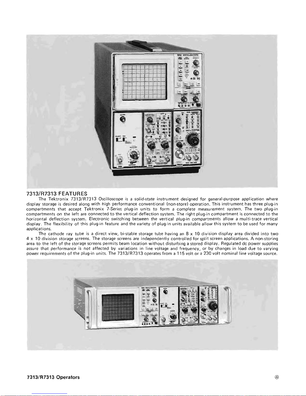
FEATURES
The
Tektronix
7313/RJ313
Oscilloscope
is a solid-state instrument designed for general-purpose application where
display storage is desired along
with
high performance conventional (non-store) operation.
This
instrument has three plug-in
compartments that accept Tektronix 7-Series plug-in units
to
form a complete measurement sysrem.
The
two plug-in
compartments on the left are connected
to
the vertical deflection system. The right plug-in compartment
is
connected to the
horizontal deflection system. Eleczronic switching between the vertical
plug-in
compartments
allow
a
multi-trace vertical
display. The flexibility of this plug-in feature
and
the
variety
af
plug-in units available allow this system to be
used
for many
applications.
The cathode
ray
tube is a direct view. bi-stable storage tube having an
8 x 10
division display area divided into two
4
x
10
division storage screens,
The
storage screens are independently controlled
for
split screen applfcations. A non-storing
area to the left of the storage screens permits
beam
location without disturbing a stored display. Regulated
dc
power supplies
assure that performance
is
not affected
by
variations
in
line voltage and frequency, or by changes in load due to varying
power requirements of the plug-in units.
The
7313/R7313
operates from
a
115
volt
or
a
230
volt nominal line voltage source.
7313/R7313
Operators
8
Page 8
Section 1-731 3lR7313 Operators
OPERATING INSTRUCTIONS
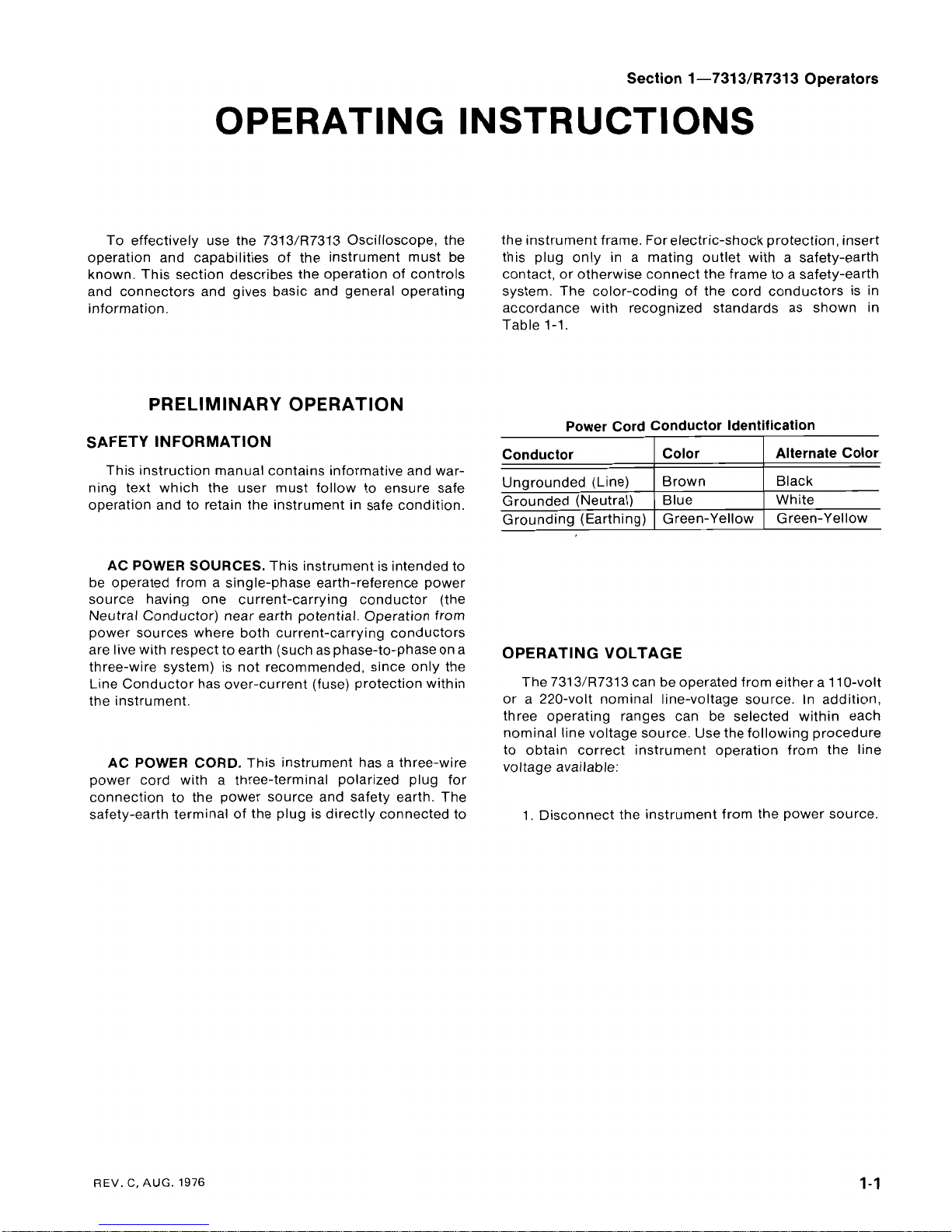
To effectively use the 7313/R7313 Oscilloscope, the the instrument frame.
for electric-shock
protection, insert
operation and capabilities of the instrument must be this plug only in a mating outlet with a safety-earth
known. This section describes the operation of controls contact, or otherwise connect the frame to a safety-earth
and connectors and gives basic and general operating system. The color-coding of the cord conductors is in
information. accordance with recognized standards as shown in
Table
1-1.
PRELIMINARY OPERATION
Power Cord Conductor Identification
SAFETY INFORMATION
Conductor Color Alternate Color
This instruction manual contains informative and war-
ning text which the user must follow to ensure safe
Ungrounded (Line)
Black
White
operation and to retain the instrument in safe condition.
Grounded (Neutral)
Grounding (Earthing) Green-Yellow Green-Yellow
AC POWER SOURCES.
This instrument is intended to
be operated from a single-phase earth-reference power
source having one current-carrying conductor (the
Neutral Conductor) near earth potential. Operation from
power sources where both current-carrying conductors
are live with respect to earth (such as phase-to-phase on a
three-wire system) is not recommended, since only the
Line Conductor has over-current (fuse) protection within
the instrument.
AC POWER CORD.
This instrument has a three-wire
power cord with a three-terminal polarized plug for
connection to the power source and safety earth. The
safety-earth terminal of the plug is directly connected to
OPERATING VOLTAGE
The 731 3/R7313 can be operated from either a 11 0-volt
or a 220-volt nominal line-voltage source. In addition,
three operating ranges can be selected within each
nominal line voltage source. Use the following procedure
to obtain correct instrument operation from the line
voltage available:
1.
Disconnect the instrument from the power source.
REV.
C,
AUG.
1976
Page 9
Operating Instructions-7313/R7313 Operators
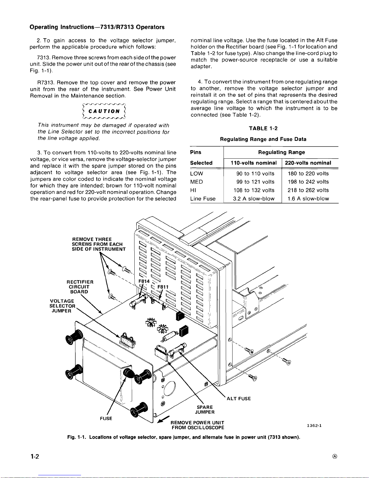
2. To gain access to the voltage selector jumper, nominal line voltage. Use the fuse located in the Alt Fuse
perform the applicable procedure which follows:
holder on the Rectifier board (see Fig. 1-1 for location and
Table 1-2 for fuse type). Also change the line-cord plug to
7313. ~emove three screws from each sideof the Power
match the power-source receptacle or use a suitable
unit. Slide the power unit out of the rearof the chassis (see
adapter,
Fig. 1-1).
R7313. Remove the top cover and remove the power
unit from the rear of the instrument. See Power Unit
Removal in the Maintenance section.
CAUTION
This instrument may be damaged if operated with
the Line Selector set to the incorrect positions for
the line voltage applied.
3. To convert from 110-volts to 220-volts nominal line
voltage, or vice versa, remove the voltage-selector jumper
and replace it with the spare jumper stored on the pins
adjacent to voltage selector area (see Fig. 1-1). The
jumpers are color coded to indicate the nominal voltage
for which they are intended; brown for 110-volt nominal
operation and red for 220-volt nominal operation. Change
the rear-panel fuse to provide protection for the selected
4. To convert the instrument from one regulating range
to another, remove the voltage selector jumper and
reinstall it on the set of pins that represents the desired
regulating range. Select a range that iscentered about the
average line voltage to which the instrument is to be
connected (see Table 1-2).
TABLE
1-2
Regulating Range and Fuse Data
REMOVE THREE
SCREWS FROM EACH
RECTIFIER
REMOVE POWER UNIT
FROM OSCILLOSCOPE
I
Pins
Selected
LOW
MED
HI
Line Fuse
Fig.
1-1.
Locations of voltage selector, spare jumper, and alternate fuse in power unit (7313 shown).
Regulating Range
110-volts nominal
90 to 110 volts
99 to 121 volts
108 to 132 volts
3.2 A slow-blow
220-volts nominal
180 to 220 volts
198 to 242 volts
218 to 262 volts
1.6 A slow-blow
Page 10
Operating Instructions-7313fR7313 Operators
PLUG-IN UNITS
The 7313lR7313 is designed to accept up to three
Tektronix 7-series plug-in units. This plug-in feature
allows a variety of display combinations and also allows
selection of polarity, sensitivity, display mode, etc. to meet
the measurement requirements. In addition, it allows the
oscilloscope system to be expaned to meet future
measurement requirements. The overall capabilities of the
resultant system are in large part determined by the
characteristics of the plug-in selected. Refer to the
Tektronix Products catalog for specifications of plug-in
units currently available.
To install a plug-in unit into one of the plug-in
compartments, align the slots in the top and bottom of the
plug-in with the associated guide rails in the plug-in
compartment. Push the plug-in unit firmly into the plug-in
compartment until it locks into place. To removea plug-in,
pull the release latch on the plug-in unit to disengage it
and pull the unit out of the plug-in compartment. Plug-in
units can be removed or installed without turning off the
instrument power.
All of the plug-in compartments do not have to be filled
to operate the instrument; the only plug-ins needed are
those required for the measurement to be made. At
environmental extremes, excess interference may be
radiated into or out of the instrument through the plug-in
compartments. To reduce such interference, or to meet
EM1 specifications on factory equipped Option 3 or field
EM1 modified instruments, all unused plug-in com-
partments must be covered with an EM1 shielded blank
plug-in panel. Order or use only Tektronix Part No. 016-
0155-00. One is required for each unused compartment.
When the 7313/R7313 is calibrated in accordance with
the calibration procedure given in the service manual, the
vertical and horizontal gains are normalized. This allows
calibrated plug-in units to be changed from one plug-in
compartment to another without recalibration. However,
the basic calibration of the individual plug-in units should
be checked when they are installed in this system to verify
their measurement accuracy. See the operating instruc-
tions section of the plug-in unit instruction manual for
verification procedure.
The plug-in versatility of the
7313/R7313 allows a
variety of display modes with many different plug-in units.
The following information is provided to aid in plug-in unit
selection.
To produce a single-trace display, install a single-
channel vertical unit (or dual-channel unit set for single-
channel operation) in either of the vertical compartments;
for dual-trace displays, either install a dual-channel
vertical unit in one of the vertical compartments or install a
single-channel vertical unit in each vertical compartment.
A combination of a single-channel and dual-channel
vertical unit allows a three-trace display; likewise, a
combination of two dual-channel vertical units allows a
four-trace display.
Non-delayed single-trace displays can be obtained
with a single-trace time-base unit.
A
dual-trace time-base
unit must be used for delayed-sweep displays.
X-Y displays can be obtained in two ways with the
7313/R7313 system. If a 7B-series time-base unit is
available that has an amplifier feature, the
X
signal can
either be routed through one of the vertical units via the
internal-trigger pickoff circuitry to the horizontal system,
or connected to the external horizontal input connector of
the time-base unit. Then, the vertical signal
(Y)
is con-
nected to the remaining vertical unit. Also, a 7A-series
amplifier plug-in can be installed in one of the horizontal
compartments for X-Y operation.
Special purpose plug-ins may have specific restrictions
regarding the plug-in compartments in which they can be
installed. This information will be given in the instruction
manuals for these plug-ins. Refer to the Tektronix
Products catalog for additional information on plug-in
unit selection.
NOTE
Later production of rackmount ocilloscopes are
provided with support posts between the individual
plug-in compartments.
A
post or posts must be
removed if a multi-width plug-in is to
be
installed. To
remove a post, unfasten the screws that secure it at
the top and bottom of the plug-in housing.
CONTROLS AND CONNECTORS
EXTERNAL
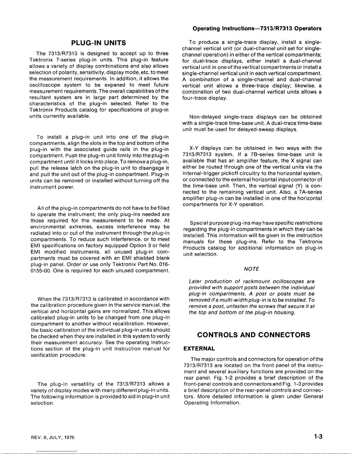
The major controls and connectors for operation of the
7313/R7313 are located on the front panel of the instru-
ment and several auxiliary functions are provided on the
rear panel. Fig. 1-2 provides a brief description of the
front-panel controls and connectorsand Fig. 1-3 provides
a brief description of the rear-panel controls and connec-
tors. More detailed information is given under General
Operating Information.
REV. B,
JULY,
1975
Page 11
Operating
Instructions-7313/R7313
Operators
a
INTENSITY.
Varies brightness of
cit
display.
@
READOUT.
Varies
brightness
of
rsadout
portion
of
cn
display.
@
FOCUS.
Provides
optimum display definition.
@
BEAMFINDER.
Returns
crt
display
by
compressing vertical
and
horizontal deflection within graticuls
area.
@
GRAT
ILLUM. Varier gratieule illumination.
@
TRIG
SOURCE.
Selects
source
of
trigger signal
for
time-bass unit.
@
VERT
MODE. Selects vertical plug-in compartment that provider vertical deflection signal.
@
STORE
(UPPER
and
LOWER).
Selects
storage
operation.
@
ENHANCE
[UPPER
and
LOWER).
Increaser writing
rate
for
storage
of
single
sweep
displays.
10
AUTO ERASE
{UPPER
and
LOWER).
Stores
the
crt
display at
the
end of each
sweep
and inhibits further
O
sweeps
for
a
time selected
by
the
VIEW
TIME
control.
@
ERASE
(UPPER
and
LOWER).
Manually
eraser
stored
diglay.
@
VIEW
TIME.
Determiner variable viewing interval
of
stored display.
@
LOCATE.
Pushbuttan switch unblankr
the
crt
to
pravids
in
indication
of
the
sweep
starting point.
@
INTEGRATE.
Permits
storage
of
very
fast
rap~titive signals.
@
ENHANCE
Level
(Level not labeled).
Provides
a
selectable increase
in
writing
speed
for
single
sweep
displays.
@
CALIRRATOR Pin
jack<
pmvirlr
rl
V,
0.4
V,
and
40
rnV
~utputs
st
a
OM
kilohertz repetition
rate.
Oc
output
can
be
selected
by
an
internal
selector.
@
POWER.
POWER
switch
controls
power
to
the instrurnenl;
POWER
light indicates
that
the
power
switch
is
on
and
the
instrument
is
connected
to
the
pawer
source.
@
Camera
Power
(not
labeled).
Provider
pawer
output
and
receives
remote
single
sweep
reset
for
compatible
camera
systems.
fig.
1-2.
Front-pmel
controls
and
connectom.
Page 12

Operating
Instructions-7313ER7313
Operators
@
FUSE. Line voltage
fuse
for instrument.
VERT
SIG
OUT
(Delete with Option
7).
Vertical
signal
selected
by
TRIG
SOURCE
and
VERT
MODE
@
switches
(Left,
Right.
Alf.
and
Add).
@
+GATE
OUT
(Delete with Option
7).
Gate rignal selected by rear-panel
gate
selector
switch
(MAIN,
AUXILIARY, and
DELAY).
@
+
SAWTOOTH
OUT
(Delete
with
Option
71.
Positive-going sawtooth
signal
from time-base unit.
@
REMOTE ERASE
IN
(Delete with
Option
7).
Provider
input
for
an
external rignal
to
erase
the
stored
display.
@
EXT
SS
RESET
IN (Delete with Option
7).
Provider
input for
an
external rignal
to
reset
the
sweep
(Time-
base
unit
operating in Single
Sweep
mode).
@
EXT
Z
AXIS
IN.
Input
for
intensity modulation
of
crt
display.
Flg.
6-3.
Rear-panel
controls
and
connectors.
Page 13
Operating Instructions-7313/R7313 Operators
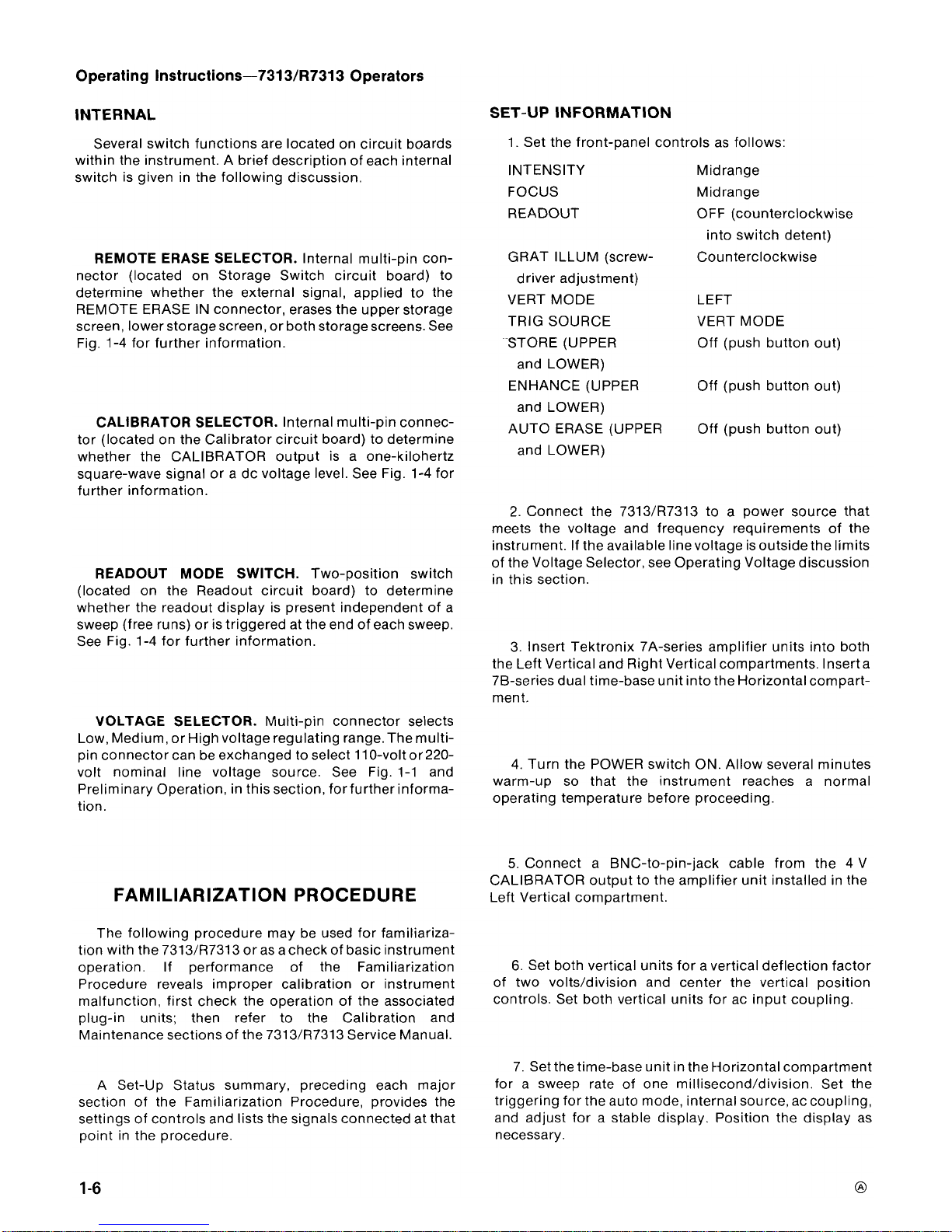
INTERNAL
SET-UP
INFORMATION
Several switch functions are located on circuit boards
within the instrument. A brief description of each internal
switch is given in the following discussion.
REMOTE ERASE SELECTOR.
Internal multi-pin con-
nector (located on Storage Switch circuit board) to
determine whether the external signal, applied to the
REMOTE ERASE IN connector, erases the upper storage
screen, lower storage screen, or both storage screens. See
Fig. 1-4 for further information.
CALIBRATOR SELECTOR.
Internal multi-pin connec-
tor (located on the Calibrator circuit board) to determine
whether the CALIBRATOR output is a one-kilohertz
square-wave signal or a dc voltage level. See Fig. 1-4 for
further information.
READOUT MODE SWITCH.
Two-position switch
(located on the Readout circuit board) to determine
whether the readout display is present independent of a
sweep (free runs) or is triggered at the end of each sweep.
See Fig. 1-4 for further information.
VOLTAGE SELECTOR.
Multi-pin connector selects
Low, Medium, or High voltage regulating range. The multi-
pin connector can be exchanged to select 110-volt or 220-
volt nominal line voltage source. See Fig. 1-1 and
Preliminary Operation, in this section, for further informa-
tion.
FAMILIARIZATION PROCEDURE
The following procedure may be used for familiariza-
tion with the 7313/R7313 or as a check of basic instrument
operation. If performance of the Familiarization
Procedure reveals improper calibration or instrument
malfunction, first check the operation of the associated
plug-in units; then refer to the Calibration and
Maintenance sections of the 7313/R7313 Service Manual.
A Set-Up Status summary, preceding each major
section of the Familiarization Procedure, provides the
settings of controls and lists the signals connected at that
point in the procedure.
1. Set the front-panel controls as follows:
INTENSITY Midrange
FOCUS Midrange
READOUT OFF (counterclockwise
into switch detent)
GRAT
ILLUM (screw- Counterclockwise
driver adjustment)
VERT MODE LEFT
TRIG SOURCE VERT MODE
STORE (UPPER Off (push button out)
and LOWER)
ENHANCE (UPPER Off (push button out)
and LOWER)
AUTO ERASE (UPPER
Off (push button out)
and LOWER)
2. Connect the
7313/R7313 to a power source that
meets the voltage and frequency requirements of the
instrument. If the available linevoltage is outside the limits
of the Voltage Selector, see Operating Voltage discussion
in this section.
3. Insert Tektronix 7A-series amplifier units into both
the Left Vertical and Right Vertical compartments. lnserta
76-series dual time-base unit into the Horizontal compart-
ment.
4. Turn the POWER switch ON. Allow several minutes
warm-up so that the instrument reaches a normal
operating temperature before proceeding.
5.
Connect a BNC-to-pin-jack cable from the 4 V
CALIBRATOR output to the amplifier unit installed in the
Left Vertical compartment.
6.
Set both vertical units for a vertical deflection factor
of two volts/division and center the vertical position
controls. Set both vertical units for ac input coupling.
7. Set the time-base unit in the Horizontal compartment
for a sweep rate of one
millisecond/division. Set the
triggering for the auto mode, internal source, ac coupling,
and adjust for a stable display. Position the display as
necessary.
Page 14

Operating Instructions-7313lR7313 Operators
Fig.
1-4.
Location and function of internal selectors.
Page 15

Operating Instructions-7313lR7313 Operators
DISPLAY CONTROLS
8.
Adjust the INTENSITY control throughout its range;
then adjust so that the trace is at the desired viewing level.
9.
Adjust the FOCUS control so the top and bottom of
the displayed square wave are as thin as possible but not
elongated.
NOTE
The oscilloscope system contains circuitry to
automatically protect the crt against damage due to
excessive crt beam current. If the intensity control is
set to a point where crt phosphor damage could
occur, these circuits limit the beam current to a safe
level. The circuit action will also cause the trace to
defocus (widen), which indicates that the INTEN-
SITY should be reduced. Therefore, if the FOCUS
adjustment cannot be made satisfactorily, reduce
the INTENSITY and repeat step
9.
10. Rotate the GRAT ILLUM screwdriver control
throughout its range and notice that thegraticule Iinesare
illuminated as the control is turned clockwise. Set the
control so that the graticule lines are illuminated as
desired.
11. Set the deflection factor of the Left Vertical plug-in
unit to 0.1
volt/division. Notice that asquare-wave display
is not visible, since the deflection exceeds thescan areaof
crt.
12. Press the BEAMFINDER. Notice that the display is
returned to the viewing area in a compressed form.
Release the
BEAMFINDER switch and notice that the
display again disappears from the viewing area.
13. With the
BEAMFINDER switch pressed in, increase
the deflection factor of the Left Vertical
BE nit
until the
display is reduced to about two
divisionsvertically.Adjust
the Left Vertical unit position control to center the
compressed display about the center of the graticule.
Release the BEAMFINDER and notice that the display
remains within the viewing area.
NOTE
Readout operation steps apply only when the
7313/R7313 and the plug-in units installed in the
7313/R7313 are equipped with a Readout System.
73131R7313 Oscilloscopes with Option 1 do not
contain a Readout System.
14. Turn the READOUT control clockwise (out of
switch detent) until an alphanumeric display is visible
within the top or bottom division of the crt. Change the
deflection factor of vertical unit that is selected for display.
Notice that the readout portion of the display changes as
the deflection factor is changed. Likewise, change the
sweep rate of the time-base unit and notice that the
readout display for the time-base unit changes as the
sweep rate is changed.
15. Sequentially select all of the VERT MODE push
buttons. Notice that the readout from a particular plug-in
unit occupies a specific location on the display area. If
either of the plug-in units is a dual unit, notice that the
readout for channel
2
appears within the lower division of
the crt. Return the VERT MODE switch to LEFT.
16. Set the time-base unit for magnified operation.
Notice that the readout display changes to indicate the
correct magnified sweep rate. If a readout-encoded 10X
probe is available for use with the vertical unit, install it on
the input connector of the Right Vertical plug-in unit and
set the VERT MODE switch to RIGHT. Notice that the
deflection factor indicated by the readout is increased by
10 times when the probe is added. Return the time-base
unit to normal sweep operation and disconnect the 10X
probe.
17. Switch the vertical and horizontal unit deflection
switches (Volts/Div, Time/Div) to the uncalibrated posi-
tion. Notice the
>
symbol that precedes the readout
display. Return the vertical and horizontal unit deflection
switches to the calibrated position.
VERTICAL AND HORIZONTAL SYSTEM CON-
TROLS
Set the 7313/R7313 controls as follows:
INTENSITY
FOCUS
As desired
As desired
READOUT
As desired
GRAT ILLUM (screw- As desired
driver adjustment)
VERT MODE A LT
TRIG SOURCE VERT MODE
STORE (UPPER
Off (push button out)
and LOWER)
ENHANCE (UPPER
Off (push button out)
and LOWER)
AUTO ERASE (UPPER
Off (push button out)
and LOWER)
CALIBRATOR
4 V output connected to
the Left Vertical and
Right Vertical units
with a BNC-to-pin-jack
cable and a
BNC-to-
BNC jumper lead.
Page 16

Operating Instructions-7313/R7313 Operators
Set the associated equipment as follows:
Left Vertical unit
Deflection factor, 2 V/Div;
position, centered in
the top half of the
graticule; input
coupling ac.
Right Vertical unit
Horizontal unit
Deflection factor, 2 V/Div;
position, centered in
the bottom half of the
graticule; input
coupling, ac.
Deflection factor, 1 ms;
triggering, auto mode,
ac coupling, internal
source, level adjusted
for stable display.
18. Set the VERT MODE switch to LEFT. Rotate the
position controls of the Left and Right Vertical units and
notice that the position control of only the Left Vertical
unit has any affect on the vertical position of thedisplayed
trace.
19. Select the RIGHT VERT MODE. Notice that only the
position control of the Right Vertical unit hasany affect on
the vertical position of the displayed trace.
20. Select the ALT VERT MODE. Notice that two traces
are displayed on the crt. The upper trace is produced by
the Left Vertical unit and the lower trace is produced by the
Right Vertical unit. Change the sweep rate of the
time-
base unit to 50 millisecond/division. Notice that the
display alternates between the Left Vertical and Right
Vertical plug-in units after each sweep. Return the sweep
rate to one millisecond/division.
21. Select the CHOP VERT MODE. Notice that two
traces are displayed on the crt. Both vertical units are
displayed on each sweep on a time-sharing basis.
22. Select the ADD VERT MODE. Check for an added
display approximately four divisions iri amplitude. Notice
that the position control of either vertical unit will vertically
position the added display. Return the VERT MODE
switch to LEFT.
CALIBRATOR AND TRIGGERING CONTROLS
Set the 7313/R7313 controls as follows:
INTENSITY As desired
FOCUS
As desired
READOUT
As desired
GRAT ILLUM (screw- As desired
driver adjusment)
VERT MODE ALT
TRIG SOURCE VERT MODE
STORE (UPPER
Off (push button out)
and LOWER)
ENHANCE (UPPER
Off (push button out)
and LOWER)
AUTO ERASE (UPPER
Off (push button out)
and LOWER)
CALIBRATOR
4
V output connected to
the Left and Right
Vertical units with a
BNC-to-pin-jack
cable and a BNC-to
BNC jumper lead.
Set the associated equipment as follows:
Left Vertical unit
Deflection factor, 2
V/Div;
position, Left Vertical
unit display centered
in the top half of the
graticule; input
coupling, ac.
Right Vertical unit
Deflection factor, 2
V/Div;
position, Right Vertical
unit display centered
in the bottom half
of the graticule; input
coupling, ac.
Horizontal unit
Deflection factor, 1 ms;
triggering, auto mode,
ac coupling, internal
source, level adjusted
for a stable display.
Page 17

Operating Instructions-7313lR7313 Operators
23. Set the VERT MODE switch to LEFT. Change the
CALIBRATOR pin-jacks and notice that 4 V, 0.4 V, and
40 mV outputs can be obtained (change the amplifier unit
defection as necessary). The CALIBRATOR output must
be terminated in a one-megohm load for stated output. Set
The CALIBRATOR pin-jacks for 4 V output and set the
amplifier deflection factor to two volts/division.
24. Adjust the time-base unit triggering controls for a
stable display. Disconnect the CALIBRATOR signal froni
the Right Vertical unit. Sequentially select all VERT MODE
switch settings. Notice that a stable display is obtained in
all positions of the VERT MODE switch (as reference trace
is provided in the RIGHT VERT MODE position). Adjust
the time-base unit triggering level control as necessary.
25. Set the TRlG SOURCE switch to LEFT. Sequential-
ly select all VERT MODE switching settings. Notice that a
stable display is obtained in all positions of the VERT
MODE switch (a reference trace is provided in the RIGHT
VERT MODE position). Adjust the time-base unit trigger-
ing level control as necessary.
26. Set the TRlG SOURCE switch to RIGHT. Sequen-
tially select all VERT MODE switch settings and notice that
a stable display cannot be obtained in any
position.This is
because there is no input signal connected to the Right
Vertical unit.
27. Disconnect the 4 V CALIBRATOR signal from the
Left Vertical unit and connect it to the Right Vertical unit.
Sequentially select all VERT MODE switch settings.
Notice that a stable display is obtained in all VERT MODE
switch settings (a reference trace is provided in the LEFT
VERT MODE position). Adjust the time-base unit trigger-
ing level control as necessary.
28. Set the TRlG SOURCE switch to VERT MODE.
Sequentially select all VERT MODE switch settings.
Notice that a stable display is obtained in all VERT MODE
switch settings (a reference trace is provided in the LEFT
VERT MODE position). Adjust the time-base unit trigger-
ing level control as necessary.
29.
Set the TRlG SOURCE switch to LEFT. Sequential-
ly select all VERT MODE switch settings and notice that a
stable display cannot be obtained in any position. This is
because there is no signal connected to the Left Vertical
unit.
31. Set the VERT MODE switch to CHOP and the TRlG
SOURCE switch to LEFT and then to RIGHT. Notice that
the chopped display can be triggered from either vertical
compartment.
STORAGE CONTROLS
Set the 7313/R7313 controls as follows:
INTENSITY As desired
FOCUS
As desired
READOUT
As desired
GRAT
ILLUM (screw-
,
As desired
driver adjustment)
VERT MODE CHOP
TRIG SOURCE LEFT
STORE (UPPER
Off (push button out)
and LOWER)
ENHANCE (UPPER
Off (push button out)
and LOWER)
AUTO ERASE (UPPER
Off (push button out)
and LOWER)
CALIBRATOR
4 V output connected to
the Left and Right
Vertical units with a
BNC-to-pin-jack
cable to a
BNC-to-
BNC jumper lead.
Set the associated equipment as follows:
Left Vertical unit Deflection factor, 2 V/Div;
position, Left Vertical
unit display centered
in the top half of the
graticule; input
coupling, ac.
Right Vertical unit
Deflection factor, 2 V/Div;
position, Right Vertical
unit display centered
in the bottom half
of the graticule; input
coupling, ac.
Horizontal unit
30. Connect the 4 V CALIBRATOR signal to both
vertical units. Set the TRlG SOURCE switch to VERT
MODE and the VERT MODE switch to ALT. Check that
both traces of the alternate display are stable.
Deflection factor, 1 ms;
triggering, auto mode,
ac coupling, internal
source, level adjusted
for a stable display.
Page 18

Operating Instructions-731 3lR7313 Operators
32. Turn the INTENSITY control fully coun-
terclockwise. Press in both STORE push buttons. Notice
the normal storage mode background light level present
on the storage screens. Advance the INTENSITY control
slowly clockwise to produce awaveform display of normal
intensity; then return the INTENSITY control to minimum
intensity (fully counterclockwise). Notice a stored
waveform of moderate brightness. Press the UPPER
ERASE push button and then the LOWER ERASE push
button. Notice that each half of the crt display can be
erased or stored independently.
33. Set both STORE push buttons to their non-store
position (push buttons out). Set the
7313/R7313 and the
associated plug-in units for a stable display of normal
intensity. Set the time-base unit for single sweep opera-
tion and engage both 7313/R7313 STORE push buttons.
Apply a single sweep trace by pressing the time-base unit
reset push button. Notice a stored display on the UPPER
and LOWER storage areas. If the display is not stored,
increase the INTENSITY and repeat the demonstration.
34. Press both ERASE push buttons. Press the
LOCATE push button and notice dots slightly to the left of
the sweep starting point. The LOCATE function is useful
to locate and position the trace while the sweep is held off
(single sweep operation). Return the time-base unit to a
normal triggering mode (non-single sweep), and adjust
for a stable display.
35. Engage both AUTO ERASE push buttons. Notice
that one sweep is displayed on the crt and further sweeps
are locked out until thestored display iserased. Rotatethe
VIEW TIME control throughout its
rangeand note that this
control varies the amount of time that the display remains
stored before it is erased.
36. Rotate the VlEW TlME control fully clockwise. As
soon as the display is automatically erased and another
trace is stored, press both ERASE push buttons. Notice
that the crt is erased and other sweeps are locked out
during the period selected by the
VlEW TlME control.
Disengage both AUTO ERASE push buttons and both
STORE push buttons (push buttons out).
37. Set the time-base unit time/division switch to
0.2 microseconds/division. Adjust the INTENSITY control
fully clockwise. Position the rising portion of the waveform
within the graticule area. Adjust the INTENSITY control so
that the trace is just visible. Press both STORE push
buttons. Notice the normal storage mode background
light on the crt. Press the INTEGRATE push button
momentarily (a fraction of a second to several seconds is
reasonable). Notice a normal fully-stored display. If the
trace does not fully store on the first attempt, repeat the
integration for a longer period or with higher intensity.
Disengage both STORE push buttons and press both
ERASE push buttons. Remove the CALIBRATOR signal
from both vertical units.
38. Apply a sine-wave signal of approximatley
300 kilohertz to the Left Vertical unit. Set the
TRIG
SOURCE and VERT MODE switches to LEFT. Adjust the
amplifier unit for three divisions of display, centered on
the graticule. Adjust the oscilloscope INTENSITY for a
moderately bright trace. Set the time-base unit for single
sweep operation and engage both 7313/R7313 STORE
push buttons. Press the time-base unit reset push button
to obtain a single sweep trace. Notice that a complete
stored display cannot be obtained at any setting of the
INTENSITY control.
39. Press both ERASE push buttons; then press both
ENHANCE push buttons. Apply a single sweep trace by
pressing the reset push button. While repeatedly erasing
and applying a single-sweep signal, adjust the ENHANCE
Level control sufficiently clockwise to completely store
the display without fading the target positive (it may be
necessary to vary the oscilloscope intensity).
GENERAL OPERATING INFORMATION
INTENSITY CONTROLS
The 7313/R7313 has separate intensity controls for
display and display readout. The INTENSITY control
determines the brightness of only the signal display; the
READOUT control determines the brightness of only the
readout portion of the crt display.
The setting of the INTENSITY control may affect the
correct focus of the display. Slight re-adjustment of the
FOCUS control may be necessary when the intensity level
is changed. Do not turn the intensity control higherthan is
necessary to provide a stable display.
Be careful that the INTENSITY control is not set too
high when changing the time-base unit sweep rate from a
fast to a slow sweep rate or when changing to the X-Y
mode of operation. The oscilloscope system incorporates
protection circuitry which automatically reduces the
display intensity to a lower level when the time-base unit is
set to a slow sweep rate. This reduces the danger of
damaging the crt phosphor at slower sweep rates.
CRT light filters reduce the observed light output from
the crt. When using these filters, avoid advancing the
INTENSITY control to a setting that may burn the crt
phosphor.
Page 19

Operating Instructions-7313lR7313 Operators
DISPLAY FOCUS
LIGHT FILTER
The FOCUS control allows adjustment for best defini-
tion of the crt display. Slight re-adjustment of this control
may be necessary as the display conditions change. If a
properly focused display cannot be obtained with the
FOCUS control, the internal Astigmatism adjustment
must be re-set; see the Calibration section in the
7313/R7313 Service Manual.
The graticule of the7313/R7313 is marked on the inside
of the faceplate of the crt, providing accurate, no-parallax
measurements. The graticule is divided into eight vertical
and ten horizontal divisions. Each division is
0.975 centimeters square. In addition, each major division
is divided into five minor divisions. The vertical gain and
horizontal timing of the plug-in units are calibrated to the
graticuleso accurate measurements can be made from the
crt. The illumination of the graticule lines can be varied
with the GRAT
ILLUM screwdriver adjustment.
NOTE
Two types of crt graticules have been used in some
Tektronix oscilloscopes. One graticule has
0%
and
100%
risetime reference points that are separated by
6
vertical graticule divisions. The othergraticule has
the
0%
and
100%
risetime reference points
separated by 5 vertical divisions. In your manual,
illustrations of the crt face or risetime measurement
instructions may not correspond with the graticule
markings on your oscilloscope.
Figure 1-5 shows the graticule of the 7313/R7313 and
defines the various measurement lines. The terminology
defined here will be used in all discussions involving
graticule measurements. Notice the O0/0, 10, 90, and 100
markings on the left side of the graticule. These markings
are provided to facilitate risetime measurements.
SECOND
CENTER TENTH
VERTICAL
VERTICAL VERTICAL
LINE
LINE LINE
1
CENTER
HORIZONTAL
LlNE
1362-5
Fig. 1-5. Definition of measurement lines on the 7313lR7313
graticule.
The tinted filters provided with the 7313/R7313 reduce
light reflections from the face of the crt to improve contrast
when viewing the display under high ambient light
conditions. The light blue filter is recommended primarily
for non-storage operation and the light green filter is
recommended primarily for storage operation. These
filters should be removed for waveform photographs or
when viewing high writing-rate displays. To gain access to
the light filter, remove the plastic frame mask.
The
BEAMFINDER switch providesa means of locating
a display which overscans the viewing area eithervertical-
ly or horizontally. When the BEAMFINDER switch is
pressed, the display is compressed within the graticule
area. To locate and reposition an overscanned display,
use the following procedure:
1. Press in the BEAMFINDER switch.
2.
While the display is compressed, increase the ver-
tical and horizontal deflection factors until the vertical
deflection is reduced to about two divisions and the
horizontal deflection is
reduced to about four divisions
(the horizontal deflection needs to be reduced only when
operating in the
X-Y
mode).
3. Adjust the vertical and horizontal position controls to
center the display about the vertical and horizontal center
lines of the graticule.
4.
Release the BEAMFINDER switch; the display
should remain within the viewing area.
VERTICAL MODE
LEFT AND RIGHT MODE.
When the LEFT or RIGHT
push button of theVERT MODEswitch is pressed, only the
signal from the plug-in unit in theselected compartment is
displayed.
ALTERNATE MODE.
The ALT position of the VERT
MODE switch produces a display that alternates between
the plug-in units-in the Left Vertical and Right Vertical
compartments with each sweep of the crt. Although the
ALT mode can be used at all sweep rates, theCHOP mode
provides a more satisfactory display at sweep rates below
about 20 milliseconds/division. At these slower sweep
rates, alternate-mode switching becomes visually percep-
tible.
The TRIG SOURCE switch allows selection of the
triggering for an alternate display. When this switch is set
to the VERT MODE position, each sweep is triggered by
the signal being displayed on the crt. This provides a
stable display of two unrelated signals, but does not
indicate the time relationship between the signals. In
either the LEFT or the RIGHT positions, the two signals
are displayed showing true time relationship. However, if
the signals are not time-related, the display from the plug-
in unit which is not providing a trigger signal will appear
unstable on the crt.
REV.
B,
JULY,
1975
Page 20

Operating Instructions-7313lR7313 Operators
CHOPPED MODE.
The CHOP position of the VERT
MODE switch produces a display that is electronically
switched between channels at a one-megahertz rate. In
general, the CHOP mode provides the best display at
sweep rates lower than about
20
milliseconds/division, or
whenever dual-trace single-shot phenomena are to be
displayed. At faster sweep rates, the chopped switching
becomes apparent and may interfere with the display.
Correct internal triggering for the CHOP mode can be
obtained in any of the three positions of the TRlG
SOURCE switch. When the TRlG SOURCE switch is set to
VERT MODE, the internal trigger signals from the vertical
plug-in units are algebraically added and the time-base
unit is triggered from the resultant signal. Use of the LEFT
or RIGHT TRlG SOURCE positions triggers the time-base
unit on the internal trigger signal from theselected vertical
unit only. This allows two time-related signals to be
displayed showing true time relationship. However, if
signals are not time-related, the display from the channel
which is not providing the trigger signal will appear
unstable. The CHOP mode can be used to compare two
single-shot, transient, or random signals which occur
within the time interval determined by the time-base unit
(ten times selected sweep rate). To provide correct
triggering, the display which provides the trigger signal
must precede the second display in time. Sincethesignals
show true time relationship, time-difference
measurements can be made from the display.
The following general precautions should be observed
to provide the best display when using the ADD mode:
1. Do not exceed the input voltage ratingsof the plug-in
units.
2.
Do not apply large signals to the plug-in inputs. A
good rule to follow is not to apply a signal that exceedsan
equivalent of about eight times the vertical deflection
factors. For example, with a vertical deflection factor of
0.5
volt/division, the voltage applied to that plug-in unit
should not exceed
4
volts. Larger voltages may result in a
distorted display.
3. To ensure the greatest dynamic range in the ADD
mode, set the position controls of the plug-in units to a
setting which would result in a mid-screen display if
viewed in the LEFT or RIGHT positions of theVERT MODE
switch.
4.
For similar response from each channel, set the plug-
in units for the same input coupling.
TRIGGER SOURCE
The TRlG SOURCE switch allows selection of the
internal trigger signal for the time-base unit. For most
applications, this switch can be set to the VERT MODE
position. This position is the most convenient, since the
ALGEBRAIC ADDITION.
The ADD position of the
VERT MODE switch can be used to display the sum or
difference of two signals, for common-mode rejection to
remove an undesired signal, or for dc offset (applying adc
voltage to one channel to offset the dc component of a
signal on the other channel). The common-mode rejection
ratio between the vertical plug-in compartments of the
7313/R7313 is
100:l
from dc to
25
megahertz.
The overall deflection factor on thecrt in the ADD mode
is the resultant of the algebraic addition of thesignals from
the two vertical plug-in units. It isdifficult to determine the
voltage amplitude of the resultant display unless the
amplitude of the signal applied to one of the plug-in units
is known. This is particularly true when the vertical units
are set to different deflection factors, since it is not
obvious which portion of the display is a result of the
signal applied to either plug-in unit. Also, the polarity and
repetition rate of the applied signals enters into the
calculation.
internal trigger signal is automatically switched as the
VERT MODE switch is changed, or as the display is
electronically switched between the plug-in units in the
ALT position of the VERT MODE switch. It also provides a
usable trigger signal in the ADD or CHOP positions of the
VERT MODE switch, since the internal trigger signal in
these modes is the algebraic sum of the signals applied to
the vertical plug-in units. Therefore, the VERT MODE
position ensures that the time-base unit receives a trigger
signal regardless of the VERT MODE switch setting,
without the need to change the trigger source selection.
However, if correct triggering for the desired display is not
obtained in the VERT MODE position, the trigger source
can be changed to obtain the trigger signal from the plug-
in unit in either the Left Vertical or Right Vertical
compartment. The internal trigger signal is obtained from
the selected vertical compartment, whether the plug-in
unit in that compartment is selected for display on the crt
or not. If the internal trigger signal is obtained from
oneof
the vertical units, but the other vertical unit is selected for
display, the internal trigger signal must be time-related to
the displayed signal in order to obtain a triggered (stable)
display.
Page 21

Operating Instructions-7313lR7313 Operators
READOUT (Deleted
by
Option 1)
The Readout System of the 7313/R7313 allows
alphanumeric display of information on the crt along with
the analog waveform displays. The information displayed
by the Readout System is obtained from the plug-in units
which are installed in the plug-in compartments. The
characters of the readout display are written by the crt
beam on a time-shared basis with the signal waveforms.
The Readout Mode switch, (located on the Readout
circuit board) determines the operating mode of the
Readout System (see Fig.
1-4). When thisswitch, S2110, is
set to the Free-Run position, the Readout System random-
ly interrupts the waveform display to display readout
characters. The waveform display is interrupted for only
about 20 microseconds for each character that is dis-
played.
In theTriggered position the Readout System is locked
out so no characters are displayed during the sweep. At
the end of the sweep, the Readout System is triggered and
a complete frame of all applicable readout words is
displayed. This mode of operation can be used when the
trace interruptions necessary to display characters would
not otherwise allow a satisfactory waveform display to be
obtained. Also, when performing single-sweep photo-
graphy or during single-sweep storage operation, the
Triggered readout mode avoids blurring of the readout
characters due to continuous display. The trigger for the
Readout System in the Gate Triggered position is produc-
ed from the sweep gate selected by the rear-panel Gate
Selector switch (a time-base unit must be installed in the
Horizontal compartment.).
The readout information from each plug-in channel is
called a word. Up to six words of readout information can
be displayed on
the7313/R7313 crt (two channelsfor each
of three plug-in compartments). The location at which
each readout word is presented is fixed and is directly
related to the plug-in unit and channel from which it
originated.
Figure 1-6 shows the area of the graticule where the
readout from each plug-in unit and channel is displayed.
Notice that the readout from channel 1 of each plug-in unit
is displayed within the top division of the graticule, and the
readout from channel 2 is displayed directly below within
the bottom division of the graticule. Only the readout from
plug-in units or channels that are selected for display by
the VERT MODE switch or by the mode switches of dual
channel plug-in units, appear in the readout display. Some
special-purpose plug-in units may override the mode
switches to display readout, even though the
compartment is not selected for waveform display.
An "identify" feature is provided by the Readout
System to link the readout word with the orginating plug-
in unit and channel (amplifier units only). When the
"ldentify" button of an amplifier unit is pressed, the word
IDENTIFY appears in the readout location allocated to
that plug-in and channel. Other readout words in the
display remain unchanged. When the "identify" button is
released, the readout display from this plug-in channel is
again displayed. Circuitry may also be provided in the
amplifier unit that produces a noticeable change in the
analog waveform display to also identify the associated
trace when the "ldentify" button is pressed; see the plug-
in instruction manuals for details.
An "uncalibrated" feature is encoded into the readout
display. When the plug-in unit deflection factor switches
(Time/Div, Volts/Div) are in the uncalibrated position, the
>symbol is displayed preceding the readout display.
LEFT VERT RIGHT VERT HORlZ
CHANNEL
1
CHANNEL
1
CHANNEL
1
LEFT VERT RIGHT VERT HORlZ
CHANNEL
2
CHANNEL
2
CHANNEL
2
1362-6
Fig.
1-6.
Location of the readout on the crt identifying the origi-
nating plug-in compartment and channel.
STORAGE OPERATION
The storage feature of the 7313/R7313 increases the
versatility of this instrument. The crt display area is divided
into two
4
x
10
division storage screens that are in-
dependently controlled for split screen applications.
Separate STORE, ENHANCE, ERASE, and AUTO ERASE
switches allow independent control of these functions for
the UPPER and LOWER storage screens.
STORAGE
MODE.
The UPPER and LOWER STORE
push buttons determine the operating mode of the
associated display area. When the STORE push button is
out, the associated screen operates in the conventional
non-store manner. The remaining storage switches have
no effect on the operation of the instrument even though
they may be engaged. When the STORE push button is
pressed in, the assocated screen operates in the storage
mode and the associated storage functions are activated.
Page 22

Operating Instructions-7313lR7313 Operators
MANUAL ERASE.
When the UPPER or LOWER ERASE
push button is pressed, the associated storage screen is
erased. The ERASE switch overrides any of the other
storage switches, so the display can be manually erased in
any storage mode.
AUTOMATIC ERASE.
When the UPPER or LOWER
AUTO ERASE push button is pressed in, the stored
display is automatically erased after the viewing interval
selected by the VlEW TlME control. The VlEW TlME
control provides continuously variable viewing intervals
from less than 0.5 second (counterclockwise) to greater
than 10 seconds (clockwise). The view time begins at the
end of sweep. This is apparent at slow sweep rates.
REMOTE ERASE INPUT.
A ground closure (from a
positive level) applied to the rear-panel REMOTE ERASE
IN connector erases the stored display. The remote
actuation can be obtained from either an active system
(pulse generator, logic circuit, etc.) or a passive system
(switch or relay). Refer to the Specification section for
Remote Erase signal requirements.
A Remote Erase Selector (located on the Storage
circuit board) determines whether the external signal,
applied to the REMOTE ERASE IN connector, erases the
upper storage screen, lower stage screen or both storage
screens. See Fig. 1-4 for further information.
SINGLE SWEEP ENHANCEMENT AND LOCATION.
The ENHANCE mode (UPPER and LOWER) provides a
method of storing single-sweep or low repetition-rate
displays that exceed the normal writing speed of the
cathode-ray tube. This mode is not normally used for
repetitive sweeps.
NOTE
After sustained use
(6
hours or more) of the
7313lR7313
in the non-store mode or in the STORE
mode with nothing written, the writing speed may be
improved by leaving the crt target fully stored for five
to fifteen minutes. This procedure may be repeated
every few hours to refresh the storage target in
applications requiring maximum stored writing rate.
To use this feature, first obtain the best possible display
of the signal in the normal storage mode. Then press the
ENHANCE push buttons (UPPER or LOWER) and set the
ENHANCE Level control to about midrange. Apply a
single-sweep display. If the ENHANCE Level control is
properly set, the display will be stored with minimum
background luminance.
If the ENHANCE Level control is set too high, the
background luminance may obscure the desired display;
if the ENHANCE Level is too low, the display may not be
adequately stored. Therefore, experimentation is neces-
sary for an optimum enhanced display.
During single-sweep operation, the LOCATE push
button can be used to locate the trace or display while the
sweep is held off. Pressing the LOCATE push button
unblanks the crt and allows the display to be positioned
before storing. The start of
thesweep will be approximate-
ly 0.2 division to the right of the bright locate spot.
CARE OF STORAGE CRT.
To prolong the useful lifeof
the storage screens, the following precautions should be
observed when operating the 7313/R7313.
1. Use minimum beam intensity required to produce a
clear, well-defined display. Care must be observed in the
degree of writing-beam intensity that is used, particularly
when using slow sweep rates and sampling displays.
2.
Turn the INTENSITY control to minimum when
changing plug-in units. An undeflected spot on the crt
screen can burn the storage target.
3.
Do not increase beam intensity to store fast-
changing portions of a waveform. See instructions given
earlier in this section for storing fast-rise waveforms.
4. Avoid repeated use of the same area of the screen.
5. Do not leave a display on the crt screen (either
written or stored) when the display is not needed.
6.
Do not leave STORE switches pushed in when the
storage mode is not needed.
INTEGRATED FAST-RISE WAVEFORMS.
The
INTEGRATE push button permits storageof waveformsat
relatively fast sweep speeds with relatively low repetition
rates. Waveforms that would be difficult to see because of
the low duty cycle of the sweep, or have poor resolution
due to the required high setting of the INTENSITY control,
can often be stored, using the Integrate method, to
produce higher brightness or better resolution.
CAUTION
a
Do not attempt to store extremely fast-rising or fast-
falling portions of waveforms viewed at relatively
slow sweep rates. The high trace intensity required
(due to the intensity difference between the horizon-
tal and the vertical segments) could cause storage
target damage.
Page 23

Operating Instructions-7313lR7313 Operators
To use the INTEGRATE function, first obtain a
triggered well-defined display. Then, press the
INTEGRATE push button (a fraction of a second to several
seconds is reasonable). If all portions of the display are not
properly stored, repeat the integration for a longer period
with higher trace intensity.
Lower trace intensity and longer integration periods
produce optimum resolution of jitter-free signals. If in-
tegration is used too long, the stored image will broaden
and obscure the desired display. Use of the INTEGRATE
function in the AUTO ERASE mode is not recommended.
CALIBRATOR
The calibrator of the 7313/R7313 provides a convenient
signal source for checking basic vertical gain and for
adjusting probe compensation as described in the probe
instruction manual. In addition, the CALIBRATOR can be
used as a convenient signal source for application to
external equipment.
VOLTAGE. The CALIBRATOR provides accurate out-
put voltage of 40 millivolts, 0.4 volt, and 4 volts at the three
front-panel pin-jack connectors into high-impedance
loads. Output resistance is approximately 50 ohms at the
40 mV and 0.4 V pin jacks and approximately 450 ohms at
the 4 V pin jack.
CURRENT. A 40-milliampere, one-kilohertz output
current is provided when the optional current-loop
accessory (Tektronix Part No. 01 2-0259-00) is connected
between the 4 V pin-jack and ground. This output can be
used to check and calibrate current-measuring probe
systems.
WAVESHAPE. The CALIBRATOR output can be
switched for a dc level or one-kilohertz square-wave signal
via an internal selector
(P1066) on the Calibrator board.
See Fig. 1-4, in this section, for further information.
The square-wave output signal of the CALIBRATOR
can be used as a reference waveshape when checking or
adjusting the compensation of passive, high-resistance
probes. Since the square-wave output from the
CALIBRATOR has a flat top, any distortion in the dis-
played waveform is due to the probe compensation.
In the DC position; 40 mV, 0.4 V, and 4 V levels are
provided at the CALIBRATOR pin-jacks. When the
40 milliampere current loop is connected between the 4 V
output and GND, 40 milliamperes of dc current is provided
through the current loop.
SIGNAL OUTPUTS
NOTE
If the 7313/R7313 is ordered with Option 7, the signal
buffer assembly will not be installed in the instru-
ment. The VERT SIG OUT, +GATE OUT, +SAW-
TOOTH OUT, and the REMOTE ERASE
IN
and EXT
SS RESET
IN
rear-panel connectors are deleted.
+SAWTOOTH. The rear-panel +SAWTOOTH OUT
connector provides a positive-going sample of the saw-
tooth signal from the time-base unit in the Horizontal
compartment. The unit of time is determined by the time-
base unit time/division switch (e.g., if the time/division
switch is set to one millisecond/division, a unit of time is
one millisecond; at five milliseconds/division, a unit of
time is five milliseconds). Refer to the Specification
section for +SAWTOOTH OUT parameters.
+GATE OUT. The +GATE OUT connector provides a
positve-going rectangular output signal from the time-
base unit installed in the Horizontal compartment. The
source of the gate signal (MAINAUXILIARY, or DELAY) is
determined by the rear-panel Gate Selector switch. The
duration of the gate pulse is determined by the respective
sweep. AUXILIARY and DELAY GATE pulses can be
produced only by a compatible dual time-base unit. Refer
to the Specification section for +GATE OUT parameters.
VERTICAL SIGNAL. The VERT SIG OUT connector
provides a sample of the vertical deflection signal. The
source of this output signal is determined by the
TRIG
SOURCE switch. In the VERT MODE position of theTRIG
SOURCE switch the output signal is determined by the
setting of the VERT MODE switch. The output signal, in
the LEFT and RIGHT positionsof theVERT MODEswitch,
is obtained from the selected vertical compartment. In the
ALT position of the VERT MODE switch, the signal at the
VERT SIG OUT connector, switches between vertical
compartments along with the crt display. In the CHOPand
ADD positions of the VERT MODE switch, the output is a
composite signal. The composite signal is the resultant of
the algebraic addition of the vertical signals from the Left
Vertical and Right Vertical compartments.
The bandwidth of the VERT SIG OUT is determined by
the Amplifier plug-in unit used (see Systemsspecification
in the Specification section). Refer to the Specification
section for the parameters of the VERT SIG OUT signal.
Page 24

Operating Instructions-7313lR7313 Operators
REMOTE SINGLE SWEEP RESET (Delete with
Option 7)
An external single sweep reset signal can be applied to
the time-base unit in the Horizontal compartment through
the rear-panel EXT SS RESET IN connector. The remote
single-sweep reset actuation can by obtained from either
an active system (pulse generator, logic circuit, etc.) or a
passive system (switch or relay). Requirements for the
EXT SS RESET IN signal are given in the Specification
section.
DISPLAY PHOTOGRAHY
A permanent record of the crt display can be obtained
with an oscilloscope camera system. The instruction
manuals for the Tektronix Oscilloscope Cameras include
complete instructions for obtaining waveform
photographs. The following specific information applies
to the 7313/R7313.
The crt bezel of the 7313/R7313 provides integral
mounting for a Tektronix Oscilloscope Camera. The three
pins located on the left side of thecrt bezel connect power
to compatible camera systems. Control signals are also
received from Tektronix automatic cameras to allow
camera controlled single-shot photography (see camera
manual for further information).
When this instrument is operated in thestorage mode, a
photograph may
beeasily composed by erasing unwanted
displays as many times as necessary before the desired
display is obtained. This ability to compose a photograph
in advance prevents wasted film due to incorrect displays.
If the readout portion of the display is to be included on
waveform photographs, the following suggestions will aid
in obtaining good photographs.
1. Focus the oscilloscope display and the camera on
the center of the crt display.
2. Set the READOUT intensity control for a minimum
setting that allows the characters to be written. This
normally occurs at a slightly lower intensity level than is
necessary for complete writing of the waveform display.
Some experimentation may be necessary to establish the
correct level. Too high asetting of the READOUT intensity
control
will result in a broad, poorly defined photograph of
the readout display.
3. If single-shot photography is used, set the Readout
Mode switch to the Triggered position (see the Readout
discussion in this section for complete operating informa-
tion). Then, the readout is displayed in a single-shot
manner after the trace is complete (be sure the camera
shutter remains open at least0.5 second afterthesweep is
completed to photograph the entire readout). Also, set the
GRAT ILLUM control counterclockwise while the trace is
being photographed. Then, the graticule can be
photographed later to produce a double-exposure picture
showing complete information.
X-Y
OPERATION
In some applications, it is desirable to display one
signal versus another (X-Y) rather than against time
(internal sweep). The flexibility of the plug-in units
available for use with the 7313/R7313 provides a means of
applying an external signal to the horizontal deflection
system for this type of display. Someof the7B-series time-
base units can be operated as amplifiers in addition to
their normal use as time-base generators. This feature
allows an external signal to provide the horizontal deflec-
tion on the crt. For most of the time-base units with the
amplifier function, the X (horizontal) signal can be con-
nected either to an external input connector on the time-
base unit or it can be routed to the time-base unit through
the internal triggering system (see time-base instruction
manual for details). If the latter method is used,
theTRlG
SOURCE switch must be set so that the X (horizontal)
signal is obtained from one of the vertical units and the Y
(vertical) signal is obtained from the other vertical unit.
The advantages of using the internal trigger system to
provide the X signal are: (1) The plug-in units do not have
to be moved between compartments for X-Y operation. (2)
The attenuator switch, of the amplifier unit providing the
horizontal signal, determines the horizontal deflection
factor for full range operation.
Another method of obtaining
X-Y
display is to install
an amplifier plug-in unit in one of the horizontal plug-in
compartments (check amplifier unit gain as given in the
plug-in instruction manual to obtain calibrated horizontal
deflection factors). This method provides the best X-Y
display, particularly if two identical amplifier units are
used, since both the X and Y input systems will have the
same delay time, gain characteristics, input coupling, etc.
For further information on obtaining X-Y displays, see the
plug-in unit manuals. Also, the reference books listed
under Applications provide information on X-Y
measurements and interpreting the resultant
lissajous
displays.
Page 25

Operating Instructions-7313lR7313 Operators
INTENSITY MODULATION RASTER DISPLAY
Intensity (z-axis) modulation can be used to relate a
third item of electrical phenomena to the vertical (y-axis)
and the horizontal (x-axis) coordinates without affecting
the waveshape of the displayed signal. The z-axis
modulating signal applied to the crt circuit changes the
intensity of the displayed waveform to provide this type of
display. "Gray scale" intensity modulation can be ob-
tained by applying signals that do not completely blank
the display. Large amplitude signals of the correct polarity
will completely blank the display; the sharpest display is
provided by signals with a fast rise and fall. The voltage
amplitude required for visible trace modulation depends
upon the setting of the INTENSITY control. A two-volt
peak-to-peak signal will completely blank the display,
even at maximum intensity levels. Lower amplitude
signals can be used to only change the trace brightness,
rather than completely blank the display. Negative-going
modulating signals increase the display intensity and
positive-going modulating signals decrease the display
intensity. Useful input frequency range is dc to 10
megahertz (input voltage derating necessary above two
megahertz). The maximum input voltage should be limited
to 10 volts (dc plus peak ac). When the EXT
Z
AXlS IN is
not in use, replace the BNC cap.
Time markers applied to the EXT
Z
AXlS IN connector
provide a direct time reference on the display. With
uncalibrated horizontal sweep or external horizontal
mode operation, the time markers provide a means of
reading time directly from the display. However, if the
markers are not time-related to the display waveform, a
single-sweep display should be used (for internal sweep
only) to provide a stable display.
The following books describe oscilloscope measure-
ment techniques which can be adapted for use with this
instrument.
A
raster-typedisplay can be used to effectively increase
the apparent sweep length. For this type of display, the
trace is deflected both vertically and horizontally by
sawtooth signals. This is accomplished in the 7313/R7313
by installing a 7B-series time-base unit in one of the
vertical plug-in compartments. Normally, the time-base
unit in the vertical compartment should be set to a slower
sweep rate than the time-base unit in the horizontal
compartment; the number of horizontal traces in the raster
depends upon the ratio between the two sweep rates.
Information can be displayed on raster using several
different methods. In the ADD position of
theVERT MODE
switch, the signal from an amplifier unit can be
algebraically added to the vertical deflection. With this
method, the vertical signal amplitudeon the crt should not
exceed the distance between the horizontal lines of the
raster. Another method of displaying information on the
raster is to use the EXT
Z
AXlS IN to provide intensity
modulation of thedisplay.This typeof rasterdisplay could
be used to provide a television-type display. Complete
information on operation using the z-axis feature is given
under Intensity Modulation.
To provide a stable raster display, both time-base units
must be correctly triggered. Internal triggering is not
provided for the time-base units when they are in the
vertical compartments; external triggering must be used.
Also, blanking is not provided from the time-base units
when they are installed in a vertical compartment. To
blank out the retrace portion from the time-base unit in the
vertical compartment, special connections must be made
from this time-base unit to the blanking network of the
7313/R7313.
For further information, see the instruction manual for
the applicable time-base unit.
John D. Lenk, "Handbook of Oscilloscopes, Theory,
and Application", Prentice-Hall Inc., Englewood Cliffs,
New Jersey, 1968.
APPLICATIONS
J. Czech, "Oscilloscope Measuring Techniques",
Springer-Verlag, New York, 1965.
J.F. Golding, "Measuring Oscilloscopes", Transatlan-
tic Arts,
Inc., 1971.
Charles H. Roth Jr., "Use of the Oscilloscope",
A
Programmed Text, Prentice-Hall Inc., Englewood Cliffs,
New Jersey, 1970.
The 7313/R7313 Oscilloscope and its associated plug-
in unitcprovide a very flexible measurement system. The
capabilities of the overall system depend mainly upon the
plug-in units. Specific applications for the individual plug-
in units are described in the plug-in manuals. The overall
system can also be used for many applications which are
not described in detail either in this manaul or in the
manuals for the individual plug-in units. Contact your
local Tektronix Field Office or representative for
assistance in making specific measurements with this
instrument.
Page 26

Section 2-731 3/R7313 Operators
SPECIFICATION
lnformation given in this section of the manual applies
to both the 7313 and R7313 Oscilloscopes, except as
otherwise indicated. The R7313 is electrically identical to
the 7313, but it is adapted for mounting in a standard 19-
inch rack. Rackmounting Instructions and a dimensional
drawing for the R7313 are given in Section 3.
This instrument will meet the electrical characteristics
listed in the Performance Requirement column of Table 2-
1 following complete calibration as given in the Service
manual. The following electrical characteristics apply
over an ambient temperature range of
O0
C to +50° C,
except as otherwise indicated. Warmup time for given
accuracy is 20 minutes.
NOTE
Many of the measurement capabilities of this instru-
ment are determined by the choice of plug-in units.
The following characteristics apply to the
7313lR7373
Oscilloscope only. See the System
Specification at the end of this section for
specifications of the complete system.
TABLE
2-1
Electrical
Supplemental Information
Characteristic
VERTICAL SYSTEM
Performance Requirement
Selected
by
VERT MODE switch
See Controls and Connectors
discussion for more detail
Approximately 1 MHz
0.4 ,us to 0.6
,us
Deflection Factor (Each
Channel)
Accuracy Between Com-
partments
Low Frequency Linearity
Bandwidth
I
Isolation Between Vertical
Compartments
Vertical Display Modes
LEFT
1
ALT
ADD
,
CHOP
Repetition Rate
Time Segment From Each
compartrne;lt
Compatible with all 7000-Series
plug-in units
Less than 1% difference
0.1 division or less compression or
expansion of a two-division (at
center-screen) signal when ver-
tically positioned within
the graticule area
Dependent upon amplifier plug-in
selected. See system
specifications
At least
100:l from dc to 25 MHz
Display from left vertical unit only
Dual-trace display, alternate
between vertical units
Single-trace display added
algebraically from both vertical
units
Dual-trace display, chopped between
vertical units
Page 27

Specification-731 3lR7313 Operators
TABLE
2-1
(cont)
--
Characteristic
--
-
RIGHT
HORIZONTAL SYSTEM
VERTICAL SYSTEM (cont)
Performance Requirement
Display from right vertical
unit only
supplemental Information
TRIGGERING
Selected by TRIG SOURCE switch.
(See Controls and Connectors dis-
cussion for more detail)
Trigger Source
LEFT VERT
VERT MODE
RIGHT VERT
CALIBRATOR
Trigger signal from left vertical
unit only
Source of trigger signal determined
by vertical mode
Trigger signal from right vertical
unit only
Exclude the first 50 ns of sweep
Fastest Calibrated Sweep Rate
Deflection Factor
DC Linearity
Phase Shift Between Vertical
and Horizontal Systems
Bandwidth (Eight-Divison
Reference)
20 ns/div
Compatible with all 7000-Series
plug-in units
0.1 div or less compression or
expansion of
a
two-division (at
center-screen) signal when hor-
ziontally positioned within the
graticule area
Less than
2' from dc to 35 kHz
At least 500 kHz
Into 1 Mfl load
Approximately
1
kHz
Wave shape
Polarity
Voltage Output
Range
Accuracy
+15" C to +35" C
0°C to +50°C
Repetion Rate
Square wave or dc voltage
(dc voltage available only when
selected by internal jumper)
Positive-going, reference to baseline
at zero volts
40
mV, 0.4 V, 4 V
Within 1%
Within 2%
Page 28

Specification-731 3lR7313 Operators
TABLE
2-1
(cont)
Characteristic
OUTPUTS
CALIBRATOR (cont)
Performance Requirement
Approximately 50
fl
Approximately 450
fl
40 mA available only when current
loop accessory 01 2-0259-00 is
connected between 4 V and GND
pin jacks
Output Resistance
40 mV and 0.4 V
4 V
Current Output
Supplemental Information
Approximately 40 mA
Selected by TRIG SOURCE switch
25 mV/div
0.5 V/div
5 ns or less
f
1 graticule div from crt display
to VERT SIG OUT
950
fl
within 2%
Selected by Gate selector (rear panel)
Auxiliary gate from dual-sweep
time-base unit
0.5 V within
10%
10 V within 10%
20 ns or less
950
n
within 2%
VERT SIG OUT (Rear Panel)
(Deleted by Option 7)
Vertical Signals
Gain
Into 50 f2
Into 1 Mn
Risetime (Into 50 f2)
Centering
Output Resistance
+GATE OUT (Rear Panel)
(Deleted by Option 7)
Gate Signals
Polarity
Output
Into 50 f2
Into
1
Mn
Risetime (Into 50 f2)
Output Resistance
See System Specifications for
7300-Series instruments
LEFT, RIGHT, ALT and ADD
MAIN, AUXILIARY and DELAY
Postive-going with baseline at
0 V
within 0.1 V
Page 29

Specification-7313lR7313 Operators
TABLE
2-1
(cont)
OUTPUTS (cont)
Supplemental Information
Characteristic
SIGNAL INPUTS
Performance Requirement
50 mV/unit time' within 15%
1 V/unit time' within 10%
950
C2
within 2%
Sinking 10 mA
10 ms at 50% amplitude points
+SAWTOOTH OUT (Rear Panel)
(Deleted by Option 7)
Outpui Voltage
Into 50
0
Into 1 M0
Polarity
Rate of Rise
Into 50
0
Into 1 MG
Output Resistance
Camera Power (PI041
at
CRT Bezel)
Pin
1
(Top)
Pin
3
Signal Required
Minimum Pulse Width
Maximum Safe Input
Pin 5 (Bottom)
'Unit of time selected by time-base unit timeldivision switch.
2-4
Greater than 500 mV p-p with
non-magnified sweep
Greater than 10 V p-p with
non-magnified sweep
Positive-going with baseline at
zero volts
+15 V
Single Sweep Reset
Closure to ground within -5 V
to 4-0.5 V
+15 V (dc
+
peak ac)
Ground
Holding input level at ground locks
out automatic erase operation, but
sweep lockout still occurs for the
interval selected by VIEW TIME
control
1 V/ps
10 mA
+5 V
REMOTE ERASE IN (Rear Panel)
(Deleted by Option 7)
Voltage Level
Rate of Change
Maximum Current
Maximum Open Circuit Voltage
Maximum Safe lnput Voltage
Closure to ground (within 0.4 V)
from a positive level
+10 V (dc
+
peak ac)
Page 30

Specification-7313lR7313
Operators
TABLE
2-1
(cont)
EXT SS RESET IN
(Deleted by Option
7)
Voltage Level
Characteristic
Minimum Pulse Width
Maximum Safe lnput Voltage
SIGNAL INPUTS (cont)
Performance Requirement
Max Current
Supplemental Information
EXT Z AXIS IN
Sensitivity
Useful lnput Voltage
versus Frequency
Polarity of Operation
Maximum Safe lnput Voltage
lnput Resistance at DC
Graticule
Type
Area
Phosphor
Vertical and Horizontal
Resolution
Non-Store
Storage
Spot Centering (No
Signal Applied)
Beamfinder
Closure to ground (within -5
V
to f0.5 V) from a positive level
1
10 ps at 50°/o amplitude points
15 V (dc
+
peak ac)
I
2
volts p-p provides trace
modulation over full intensity range
2
volts p-p, dc to 2 MHz; reducing
to 0.4 V p-p at 10 MHz
Positive-going signal decreases trace
intensity; negative-going signal
increases trace intensity
I
10 V (dc + peak ac)
Approximately 500
Cl
DISPLAY
Black internal graticule
8 X 10 div (1 div=0.975 crn)
Within 0.5 division radius of graticule
center
Limits display to within graticule area
when BEAMFINDER is actuated
Page 31

Specif ication-7313fR7313 Operators
TABLE
2-1
(cont)
Storage Modes
I
Normal and Enhance
I
Supplemental Information
Characteristic
DISPLAY (cont)
Stored Writing Speed
Performance Requirement
Stored Display
Storage Type
500 div/ms minimum (5000 div/ms
enhanced)
Bi-stable, split screen
Maximum Recommended
Storage Time
Enhance Pulse
Amplitude
4 hours
Erase Time
View Time in Auto Erase
Adjustable with front-panel
ENHANCE Level Control
CHARACTER GENERATOR
Less than 0.5
sec to greater
than 10 sec
Mode
400 ms or less
Character Height
Free-run independent of sweep
Triggered at end of sweep
I
Adjustable by internal control
Selected by internal readout mode
switch
Word Location
See Fig. 1-6
POWER SOURCE
50 to 440 Hz
50 to 60 Hz
50 to 440 Hz
170 watts, 2.0 amps at 60
Hz,
115 V Line
Line Voltage Range
(AC, RMS)
110 V Nominal
220 V Nominal
Line Frequency
731
3
R7313
R7313 Option
5
Maximum Power
Consumption
1 00 V
f
10%
110
v
*loO/o
120
v
*1O0/o
200
V
f
10%
220
v
*
10%
240 V
f
10%
Page 32

Specification-7313lR7313
Operators
TABLE
2-2
Environmental
NOTE
Characteristic
This instrument will meet the electrical
characteristics given in the Performance Require-
ment column of Table
2-1
over the following en-
vironmental limits, except as otherwise indicated.
Performance
Temperature Range
Operating
Altitude
Operating
I
15,000 feet
--
Non-operating Test limit 50,000 feet
Electro-Magnetic In-
terference (EMI) in
accordance with
MIL-STD-461 A as
tested in MIL-STD-
462 (when equip-
ped with Option 3)
NOTE
Any unusedplug-in compartments
must be covered with a blankplug-
in panel
(EM1
shielded) in order to
meet EM1 specifications. See
Options section for additional
information.
Radiated inter-
ference
Interference radiated from the
instrument under test within the
given limits from 150 kilohertz to
1000 megahertz
Conducted inter-
ference
Interference conducted out of the
instrument under test through the
power cord within the given limits
from 150 kilohertz to 25 megahertz
Transportation
(packaged in-
strument, with-
out plug-ins)
--
-
Qualifies under National SafeTran-
sit Cornmitte test procedure lA,
Category I
I
TABLE
2-3
Phvsical
-
Characteristic
I
Information
Ventilation
Safe operating temperature main-
tained by convection cooling
(7313) or forced air cooling
(R7313). Automatic resetting
thermal cutout protects instrument
from overheating
STANDARD ACCESSORIES
Standard accessories supplied with the 731 3/R7313 are
given in the Mechanical Parts List illustrations in the
Service manual. For optional accessories available for use
with this instrument, see the Tektronix, Inc. catalog.
Characteristic
Finish
7313 Overall
Dimensions
(measured at
maximum points)
Height
Width
Length
Net Weight
(instrument only)
R7313 Overall
Dimensions
(measured at
maximum points)
Height
Width
Length
Net Weight
(instrument only)
SYSTEM SPECIFICATIONS
Your Tektronix 7313/R7313 oscilloscope system
provides exceptional flexibility in operation with a wide
choice of general and special purpose plug-in units. The
type number of a particular plug-in identifies its usage as
follows:
Performance
Anodized aluminum front panel,
painted cabinet
12.0 inches (30.4 cm)
8.7 inches (22.0 cm)
22.7 inches (57.6 cm)
30 pounds (13.6 kg)
5.25 inches (13.4 cm)
19.0 inches (48.5 cm)
21.5 inches (62.0 cm)
30 pounds (13.6 kg)
The first digit (7) denotes the oscilloscope system for
which the plug-in unit is
designed (7000-Series).
The second letter describes the purpose of the plug-in
unit:
A-Amplifier unit
B-"Real time" time-base unit
Page 33

Specification-7313137313 Operators
D-Digital unit
L-Spectrum analyzer
M-Miscellaneous
S-Sampling Unit
T-Sampling time-base unit
The third and fourth digits of the plug-in type number
are sequence numbers and do not carry any special
connotation.
An
"N"
suffix letter added to the normal four digit type
number identifies a unit not equipped with the circuitry
necessary to encode data for the 7000-Series readout
system.
TABLE
2-4
7313lR7313 OSCILLOSCOPE
SYSTEM VERTICAL SPECIFICATIONS
Table 2-4 lists the vertical specifications that are system dependent. For more complete specifications on plug-
in units for the 7000-Series Oscilloscope System, refer to the Tektronix, Inc. catalog.
-Deflection factor accuracy is checked as follows:
EXT CAL 0°C to 50°C-Plug-in gain set at a temperature within 10°C of operating temperature, using an external calibrator
whose accuracy is within 0.25%.
Amplifier
Plug-in Unit
7All
7A1
7A13
INT CAL 15°C to 3S°C-Plug-in gain set while operating within a temperature range of +lYC to + 35"C, using the oscilloscope
calibrator.
SIG OUT
INT CAL 0°C to 50°C-Plug-in gain set using the oscilloscope calibrator (within 1O0C of the operating temperature) in
a
temperature range between 0" C and +50° C.
Probe
Integral
None
P6053A, 54
None
P6053A, 54
BW
60 MHz
55 MHz
55 MHz
55 MHz
55 MHz
Tr
5.9 ns
6.4 ns
6.4 ns
6.4 ns
6.4 ns
BW
25 MHz
25 MHz
25 MHz
25 MHz
25 MHz
Tr
14 ns
14 ns
14 ns
14 ns
14 ns
Vertical System Deflection
Factor ~ccuracy~
EXT CAL
0' to 50°C15'
2%
2%
3%
1 .5%
1 .5%
INT CAL
to 35'C0°
3%
3%
4%
2.5%
2.5%
INT CAL
to 50°C
4%
4%
5%
3.5%
3.5%
Page 34

Section
3-731
3/R7313
Operators
RACKMOUNTING
INSTRUCTIONS
The
R7313
is
designed to
be
installed in a standard
19-
The rear mounting brackets allow this instrument
to
be
inch rack with Universal hole spacing. If a rack
with
other
mounted
in rackswith
14
5/8
to
28
1/2
inches between the
than Universal hole spacing is used, additional mounting
front and rear rails. The
R7313
must
be
properly supported
holes may need to
be
drilled.
at
the
rear. Improper support
may
result in instrument
damage.
INSTRUMENT DIMENSIONS
A
drawing showing the major dimensions
of
the
R73f
3
is
shown in
Fig.
3-6.
RACK
DIMENSIONS
HEIGHT.
At
least
5.2
inches
of
vertical space is re-
quired to mount this instrument
in
a
rack. This
gives
enough clearance for adjacent instruments
and
panels.
Additional height
may
be
required if an oscilloscope
camera is to
be
used
with this instrument.
WIDTH.
Minimum
space
between
the
front rails
of
the
rack is
17
5/6
inches. This
space
allows the slide-out
tracks to operate freely, permitting the
R7313
to
move
in
and
out
of
the
rack.
SLIDE-OUT
TRACKS
The slide-out tracks provided with this instrument
permit
it
to
be
extended out
of
the
rack
for maintenance
and calibration without removing
it
from
the
rack.
Be
sure
the
power
cord
and
signal cables are long
enough
to allow
operation in
the
extended position.
The slide-out tracks
consist
of
two
assemblies,
one
for
the
left
side of the instrument
and
one
for
the right side.
Fig.
3-1
shows the slide-out track assembly. The
stationary
section
of
each
assembly attaches to the front
and
rear
rails
of
the
rack.
The
chassis sections allow the
instrument to
be
extended
out
of
the
rack.
DEPTH.
Total depth required to mount this instrument
The
hardware needed to
mount
the tracks
to
the
rack is
in
an
enclosed-cabinet rack
is
23.9
inches.
This
allows
shown
in
Fig.
3-1.
Since enough hardware
is
supplied
to
enough
space
for air circulation, signal connections,
and
make
the
tracks compatible with a variety
of
racks
and
the
power cord.
installation methods,
some
of it may not
be
needed.
l
NTERMEOIATE
SECTION
(SLIDES
BETWEEN
STAT
lONARY
STATIONARY
SECT1
OM
SECTION
AND
CHASSlS
SECTION)
(MOUNTED
TO
RACK)
A
UTOM
AT1
C
(2 EACH1
42
EACH)
STOP
LATCH
I
I
i
STOP
LATCH
HOLE
FOR
CHASSIS
SECTION
I
FLAT
BAR
NUT
(6
EACH)
i
t
CHASSlS
SECTION
--j-
/
\
10132
PHs
10132
FHS
(MOUMTED
TO INSTRUMENT)
REAR
MOUNTING
BRACKET
(2
EACH)
SCREW
SCREW
12
EACH)
(12
EACH)
14
EACHE
Fig.
3-1. Slide-out
track
assembly.
Page 35

Rackmounting Instructions-7313/R7313 Operators
MOUNTING PROCEDURE
NOTE
1.
Select the proper front-rail mounting holes for the
If the rails of the rack are tapped, either
drill
out the
stationary sections using the measurements shown in
holes with a
0.196
inch drill, or mount the front
Fig. 3-2.
flanges in front of the rails.
2. Mount the front flanges of the stationary sections to
3. Mount the rear of the stationary sections to the rear
the front rails of the rack with a bar nut and two pan-head
rails using the method shown in Fig. 3-38 or3-3C. Besure
screws (see Fig. 3-3A).
that the tracks are level.
Fig.
3-2.
Vertical mounting position of the left stationary section and location of the thumb screw securing hole. These
dimensions also apply to the right front rail.
Page 36

LEFT REAR
CORNER OF
CABINET RACK
REAR
SUPPORT
BAR BRACKET
NUT
I
STATIONARY
(A) REAR-DEEP RACK CONFIGURATION:
Rackmounting Instructions-7313lR7313 Operators
LEFT REAR
BAR
NUT
i-
REAR
//
SUPPORT
BRACKET
(B) REAR-SHALLOW RACK CONFIGURATION:
C
TRACK
u/'
(C) FRONT
Fig.
3-3. Details for mounting stationary sections.
Page 37

Rackmounting Instructions-7313/R7313 Operators
4. Refer to Fig. 3-4 to install the instrument into the
rack.
5. See Fig. 3-5 to adjust the alignment of the stationary
sections.
6.
After the tracks operate smoothly, connect the
power cord and all necessary cables to the rear-panel
connectors. Push the instrument all the way into the rack
and secure it to the front rail of the rack with the securing
screws and washers shown in Fig. 3-2. If the securing
holes are not tapped, use a "speed-nut" or similar item to
install the securing screws.
REMOVING OR INSTALLING THE INSTRUMENT
After initial installation and adjustment of the slide-out
tracks, the instrument can be removed or installed by
following the instructions given in Fig. 3-4. No further
adjustments are required under normal conditions.
SLIDE-OUT TRACK LUBRICATION
The special finish on the sliding surfaces of the tracks
provides permanent lubrication. However, if the tracks
require additional lubrication, a thin coat of paraffin can
be rubbed onto the sliding surfaces.
/
TO INSTALL
1.
PULL THE SLIDEOUT TRACK INTERMEDIATE SECTIONS OUT TO THE FULLY EX-
TENDED POSITION.
1
2.
INSERT THE INSTRUMENT CHASSIS SECTIONS INTO THE INTERMEDIATE SECTIONS.
L
3. PRESS STOP LATCHES AND PUSH INSTRUMENT TOWARD RACK UNTIL THE LATCHES
SNAP INTO THEIR HOLES.
r
4. AGAIN PRESS STOP LATCHES AND PUSH INSTRUMENT INTO RACK.
I
5.
SECURE THE INSTRUMENT IN PLACE WITH THE FRONT-PANEL SECURING SCREWS.
DELETE THIS STEP FOR INITIAL INSTALLATION.
I
TO REMOVE
1.
REMOVE THE FRONT-PANEL SECURING SCREWS.
2.
PULL THE INSTRUMENT OUTWARD UNTIL THE STOP LATCHES SNAP INTO THE HOLES.
Fig. 3-4. Installing and removing the instrument.
Page 38

Rackmounting Instructions-7313lR7313 Operators
LOOSEN SCREWS ON BOTH SIDES (LEFT SIDE SHOWN).
ALLOW SLIDES TO SEEK PROPER WIDTH.
CENTER INSTRUMENT
RETIGHTEN SCREWS.
PUSH THE INSTRUMENT ALL THE WAY INTO THE
RACK. IF TRACKS DO NOT SLIDE SMOOTHLY, CHECK
FOR CORRECT SPACING BETWEEN THE REAR SUP-
PORTS.
Fig.
3-5.
Adjusting the slide-out tracks for smooth sliding action.
Page 39

Rackmounting Instructions-7313/R7313 Operators
Page 40

Section 4-731 3lR7313 Operators
INSTRUMENT OPTIONS
The following factory-installed optionsareavailablefor
OPTION 3
the 7313/~7313. conversion kits, for most options, are
available and can be installed at a later time. A description
of each option is given in the following discussion.
Complete option information is incorporated into the
appropriate sections of the manual. See Table 4-1 and the
Table of Contents for the location of option information.
For further information on instrument options, see your
Tektronix, Inc. catalog or contact your Tektronix Field
Office.
OPTION 1
This option deletes the Readout System. Operation of
the instrument is unchanged except that there is noalpha-
numeric display on the cathode-ray tube.
This option
provideselectro-magnetic
shielding so that
the instrument will meet the electro-magnetic interference
parameters given in the Specification section. To meet the
specifications of Option 3, all unused plug-in com-
partments must be covered with an EMI-shielded blank
plug-in panel (Tektronix part number 016-0155-00). One
blank panel is required for each unused plug-in compart-
ment.
OPTION 5 (Rackmount instruments only)
Option 5 provides a special fan circuit to allow opera-
tion of the R7313 from a power source with from 50 Hertz
to 440 Hertz line frequency.
OPTION
7
Option 7 deletes the +SAWTOOTH OUT, +GATE OUT,
VERT SIG OUT, EXT SS RESET IN, and REMOTE ERASE
IN connectors from the rear-panel of the 7313/R7313.
TABLE
4-1
Option lnformation Locator
Instrument Option
Option 1
(Deletes Read-
out System)
Option 3
(Provides EM1
shielding)
Option
5
(50 Hertz to
440 Hertz fan on
R7313 only)
Manual Section
1
Operating
Instructions
2
Specification
1
Operating
Instructions
2
Specification
2
Specification
Location of Information
Controls and Connectors
Delete READOUT Intensity information.
Delete the Readout Mode Switch information.
Delete Readout portion of Familiarization Procedure.
Electrical
Delete Character Generator specifications.
Plug-In Units
Includes EM1 operating information.
Environmental
Includes Electro-Magnetic Interference characteristics.
Electrical
Includes option
5
parameters in
Line Voltage specifications.
Page 41

lnstrument Options-7313lR7313 Operators
Table
4-1
(cont)
Option lnformation Locator
Instrument Option
Option
7
Operating lnformation
Delete the Remote Erase Input information from the
Storage Operation discussion.
(Deletes rear panel
inputs and outputs)
I
/
Delete the Signal Output discussion.
Manual Section
1
I
I
Delete the Remote Single Sweep discussion.
Location of Information
Controls and Connectors
Operating
Instructions
Delete the Vert Sig Out, +Gate Out, +Sawtooth Out,
Remote Erase In, and Ext SS Reset In information.
Delete Remote Erase In and Ext SS Reset In parameters
from Signal Inputs specifications.
2
Specification
Electrical
~elete Outputs specifications.
Page 42

MANUAL
CHANGE
1NFORMATlON
At Tektronix,
we
continually strive
to
keep
up with latest electronic developments
by
adding circuit
and
component improvements
to
our instruments
as
soon
as
they
are developed and tested.
Sometimes, due
to
printing
and
shipping requirements,
we
can't
get
these
changes immediately into printed panuals. Hence, your manual
may
contain new
change information
on
following
pages.
A
single
change
may
affect several sections. Sincethe change information
sheets
are
carried
in
the
manual until all
changes
are permanently entered,
some
duplication
may
occur. If
no
such
change
pages
appear following
this
page, your
manual is correct
as
printed.
SERVICE
NOTE
Because
of
the universal
parts
procurement problem, someelectrical
parts
in your
instrument
may
be
different
from
those described in
the
Replaceable Electrical
Parts
Lht.
The
parts
used
will
in
no
way
alter
or
cornpromi=
the
performanceor reliabWity
of
this
instrument.
They
are
installed when necessary
to
ensure
prompt
delivery to
the customer. Order
replacement
parts
from
the
Replaceable
Electrical
Parts
List.
Page 43

CALIBRATION
TEST
w
IPMENT
REPLACEMENT
Callbration
Test
Equlprnent
Chart
f
his
chart
compares
TM
500
product
performan-
to
that
of older Tektronix equipment. Only tho%
characteristics
where
significant
specification
differences occur,
are
listed.
In
some
cams the
new
instrument
may
not
be
a
total functional replacement. Additional
support
instrumentation
may
k
needed
or
a
change
in
calibration procedure
may
be
necessary.
DM
501
replaces
7013
PG
501
reptams
j07
*1
RG
502
replaces 107
108
llt
I
PG
501 - Risetime
less
than
3.5
ns
into
50
n.
PG
501
-
5
V
output pulw
3.5
ns
Rlsetlme
I
PG
502
-
5
V
output
PG
502
-
Rlsetime less
than
1
ns; 10 ns
Pmtrigger pulse
3.0
ns
into
50
R.
108
-
10
V
output pulse
'
1
ns Risetime
108-
10Y
outpu
p
11
1
-
Risetime
0.5
ns;
30
to
250
ns
Pmtrigger pulse
Performance
of
replacement equipment
is
the
same
or
better t
hrrn
equipment being mpl-aced.
PG
506
replaces
108
I%
506
-
Positive-going-
108
-
Positive
and
Negative-
trigger output sip
gang
ttlgger output
nal
ai
least 1 V;
signal, 50 ns and
1
V;
Hlgh Amplitude out-
High Amptltude output,
put,
60
v.
100
v.
PG
506
-
Does
not
have
0502-01
-
Comparator
output
chopped feature. can
be
alternately
chopped
to
a
refer-
ence
voltage.
lWA, 1906
SG
503
-
Amplitude
range
1908
-
Amplitude
range
40
rnV
5
mV
to
5.5
V
p-p.
to
10
V
p-p.
191
007-0532-01
SG
503
-
Frequency
range
0532-03
-
Frequency range
250
kHz
to
250
Mk
65
MHz
to 500
MHz.
SG
504
replaces
0670532-01
SG
504
-
Frequency
range
053S01
-
Frequency
range
245
MHz
to
1050
MHz.
65
MHz to
500
MHz.
067-o&o-w
TG
501
replam
180,
'
MOTE:
All
TM
500
generator
out1
REV
B,
JUN
1978
TG
501
-
Trigger output-
slaved
to
marker
output from
5
s8c
through
100
ns.
One
tlmemark can
be
generated at a time.
TG
501
-
Trigger
output-
slaved
to
market
output from
5
see
through
100
ns.
One
time-mark
can
Is
generrrted
at a time.
TG
501
-
Tligget output-
slaved tommarker
output
from
5
sec
through
100
ns.
One
time-mark
can
be
generated
at
a
time.
uts
are
short-proof.
All
TM
5MI
plug-in
1MA
-
Trigger
purses 1, 10,
,
100
Hz;
1,
10, and
-
100
kHz.
Multiple
time-marks can
be
generated simultan-
eously.
181
-
Multiple
timbmarks
184
-
Separate trigger
pulses
of
1
and
0.1
sec;
10,
1,
and
0.1
ms;
10
and
1
ps.
2901
-
Separate trigger
pulses,
from 5 mc
to
0.1
ps.
Multiple
tlme-marks
can
be
generated
si
rnultan-
musly.
I
I
Inelrumentr
requlre TM
WSetiea
Power
Module.
 Loading...