

Page 1

Model 7153 High Voltage Low
Current Matrix Card
Instruction Manual
Contains Operating and Servicing Information
Page 2

Page 3

Model
7153
High Voltage Low
Instruction Manual
0 1990, Keithley Instruments, Inc.
Test Instrumentation Croup
All rights reserved.
Cleveland, Ohio, U.S.A.
November 1990, First Printing
Document Number: 7153.YOLRev. A
Page 4

Page 5

SAFETY PRECAUTIONS
The following safety precautions should be observed before using the
Model 7153 and the associated instruments.
This matrix card is intended for use by qualified personnel who recognize
shock hazards and are familiar with the safety precautions required to
avoid possible injury. Read over this manual carefully before using the
card.
ALWAYS remove power from the entire system (mainframe, test instruments, DUT, etc.) and discharge any capacitors before doing any of the
following:
1. Installing or removing the matrix card from the mainframe.
2. Connecting or disconnecting cables from the matrix card.
Exercise extreme caution when a shock hazard is present at the test fixture.
User-supplied lethal voltages may be present on the fixture or the connector jack. The American National Standards Institute (ANSI) states that a
shock hazard exists when voltage levels greater than 30V RMS or 42.4V
peak are present. A good safety practice is to expect that hazardous voltage is present in any unknown circuit before measuring.
Do not exceed 1300V between any two pins or between any pin and chassis ground.
Inspect the connecting cables and test leads for possible wear, cracks, or
breaks before each use.
For maximum safety, do not touch the test fixture, test cables or any instruments while power is applied to the circuit under test.
Page 6

Do not touch any object which could provide a current path to the common side of the circuit under test or power line (earth) ground.
Do not exceed the maximum signal levels of the test fixture, as defined in
the specifications and operation section of this manual.
Do not connect the matrix card (or any other instrumentation) to humans.
Do not connect the matrix card directly to unlimited power circuits. This
product is intended to be used with impedance limited sources. NEVER
connect the tmatrix card directly to AC mains.
When connecting sources, install protective devices to limit fault current
and voltage to the card.
The chassis connections must only be used as shield connections for
measuring circuits; NOT as safety earth ground connections.
The outer shields (including the triax connector shells) of the Model
7153-TRX are not connected to safety earth ground. NEVER apply more
than 30V to these shields.
To prevent voltages from being exposed or connections from shorting together, make sure cables are properly connected before applying voltage.
Do not apply power to cables that are not connected.
Page 7

Model
MATRIX CONFIGIJRATION: 4 TOWS by 5 columns.
CROSSPOINT CONFIGURATION (Signal and Guard): Z-pole Form A.
CONNECTORTYPE: Miniature coax, M-Series Receptacle.
RELAY DRWE CURRENT: 40mA (per crosspoint).
MAx,MuM SlGNAL LEVEL:
IA carry / 0.5A switched.
IOVA peak (resistive load).
Maximum Between Any 2 Pins or Chassis: 13OOV.
Max,mum Between Signal and Guard: 200”.
CONTACT LIPB:
Cold Switching: 108closures.
Maximum Signal Level: lo5 closures.
PATH RESISTANCE: <IO per contact to rated life.
ACTUATION TIME: <2ms evctusivc of mainframe.
ISOLATION:
Path to Path: >lOW and <IpF.
Differential (Signal to Guard): >lO”Q and 4OOpF.
Gammon Mode 6tgnat and Guard to Chassis): >lOQ and 4OOpP.
CROSSTALK (Adjacent Path to Path): <-50dB at IMHz, 50 n load.
INSERTION LOSS (1 MHz, 5On Source, 5On Load): 0.1 dB typical.
3dB BANDWIDTH (500 Load): 60 MHz typical.
OPPSET CURRENT (Signal to Guard): 4pA (1OfA typical)
CONTACT POTENTIAL (Signal to Guard): <5OpV typical.
ENVIRONMENT:
Isolation and Offset Current Specifications: WC, 40% R.H.
~,~~wAI;~~~~“,;~~$$ up to 35°C at 70% R.H.
7153
Specifications
c
VIMENSIONS, WEIGHT: 30mm high x 114mm wide x 288mm long
x 11.34 in.,. Net weight 0.60 kg (20.0 oz.).
)RY
ACCESSC
surrLif3.D:
Insttiction manual
(1.18 in. x
Page 8

SECTION 1
General Information
Contains information on Model 7153 features, specifications,
and accessories.
SECTION 2
Operation
Details installation of the Model 7153 High Voltage Low Current Matrix Card within theModel 705 and 706 scanners. covers
card connections, and also discusses matrix mainfrake programming and measurement considerations.
SECTION 3
Applications
Gives three typical applications for the Model 7153, including
semiconductor switching matrix, van der Pauw resistivity mearurements, and semiconductor parameter analysis using the HP
41150.
SECTION 4
Service information
Contains Matrix card cleaning and performance verification
procedures for the matrix card.
SECTION 5
Replaceable Parts
Lists replacement pans, and also includes component layout
and schematic drawing for the Model 7153
Page 9

Table of Contents
SECTION 1 - General Information
1.1
1.2
1.3 WARRANTY INFORMATION
1.4
1.5
1.6
1.7
1.7.1
1.7.2
1.7.3
1.8
1.9
INTRODUCTION ..................
FEATURES,
MANUAL ADDENDA
SAFETY SYMBOLS AND TERMS .......
SPECIFICATIONS ..................
UNPACKING AND INSPECTION ......
Inspection for Damage
Shipment Contents
Additional Instruction Manual .......
REPACKING FOR SHIPMENT .........
OPTIONAL CABLE ASSEMBLY
.......................
.........
...............
............
...............
........
SECTION 2 - Operation
2.1
2.2
2.3
2.4
2.5 CARD INSTALLATION AND REMOVAL
2.5.1
2.5.2
2.6
2.6.1
2.6.2 Recommended Cables and Adapters
2.6.3
2.6.4
2.6.5
2.7
2.8
2.8.1
INTRODUCTION
HANDLING PRECAUTIONS
ENVIRONMENTAL CONSIDERATIONS
EQUIVALENTCIRCUIT
Matrix Card Installation
Matrix Card Removal
INSTRUMENT AND DUT CONNECTIONS
Card Connectors
General Instrument Connections
Keithley Instrument Connections
Typical Test Fixture Connections
MATRIX EXPANSION
MAINFRAME CONTROL OF MATRIX CARD
Front Panel Matrix Control
............................
....................
........................
......................
.......................
...........................
...............
...............
...............
.........................
...................
...........
...........
........
............
.......
l-l
l-l
1-2
1-2
1-2
1-3
1-3
1-3
1-3
1-3
1-3
1-4
2-1
2-2
2-2
2-2
.
2-3
2-4
2-6
2-6
2-7
2-9
2.12
2-20
2-25
2-26
2-28
2.20
Page 10

2.8.2
2.9
2.9.1
2.9.2
2.9.3
2.9.4
2.9.5
2.9.6
2.9.7
Matrix Control Over IEEE-488 Bus ...........
MEASUREMENTCONSIDERATIONS ..........
Magnetic Fields .........................
Radio Frequency Interference ..............
Ground Loops ..........................
Keeping Connectors Clean ................
Noise Currents Caused by Cable Flexing
Shielding ..............................
Guarding ..............................
SECTION 3 -Applications
......
2-33
2-35
2-35
2-36
2-37
2-38
2-39
2-39
2.41
3.1
3.2
3.2.1
3.2.2
3.3
3.3.1
3.3.2
3.3.3
3.3.4
3.3.5
3.3.6
3.3.7
3.4
INTRODUCTION ...........................
SEMICONDUCTOR TEST MATRIX ..............
System Configuration
Testing Common-Source Characteristic of FETs
RESISTIVITY TESTING USING MATRIX SWITCHING
IN A SMU TEST SYSTEM ......................
System Configuration ......................
Test Configuration .........................
Resistivity Calculations
Test Connections ..........................
Measurement Considerations
Pro
ram: Resistivity Tests Using a Switching Matrix
an Source Measure Unit ...................
d:
Program Description .......................
SMU REMOTE SENSING ......................
........... ;. .........
.....................
................
...
3-1
3-1
3-2
3-3
3-4
3-4
3-4
3-7
3-7
3-8
3-9
3-10
3-13
SECTION 4 - Service Information
4.1 INTRODUCTION . . . . .
4.2
4.3 PERFORMANCE VERIFICATION
4.3.1 Environmental Conditions . . . . 4-2
4.3.2 Recommended Test Equipment . . . . 4-2
HANDLING AND CLEANING PRECAUTIONS 4-1
4-l
4-2
Page 11

4.3.3
4.3.4
4.3.5
4.3.6
4.3.7 Differential Isolation Verification
4.3.8
4.3.9
Special Connection Requirements
Offset Current Verification
Contact Potential Verification .
Path Isolation Verification .
Common Mode Isolation Verification
Path Resistance Verification
SECTION 5 - Replaceable Parts
4-4
4-7
4-9
4-l 1
4-14
4-17
4-19
5.1 INTRODUCTION .
5.2
5.3
5.4 FACTORY SERVICE . . . . .
5.5
PARTS LIST . . . . . . . . . . . . . . . . . . . . . . . . . . . . . . . . . .
ORDERING INFORMATION
COMPONENT LAYOUT AND SCHEMATIC DIAGRAM
3-l
3-l
3-l
3-1
3-1
Page 12

List of Illustrations
SECTION 2
Figure 2-l
Figure 2-2
Figure 2-3
Figure 2-4
Figure 2-5
Figure 2-6
Figure 2-7
Figure 2-8
Figure 2-9
Figure 2-10
Figure 2-11
Figure 2-l 2
Figure 2-13
Figure 2-14
Figure 2-l 5
Figure 2-16
Figure 2-17
Figure 2-l 8
Figure 2-l 9
Figure Z-20
Figure 2-21
- Operation
Schematic of Model 7153 ..................
Card Installation in a Model 705 .............
Card Installation in a Model 706 ............
Model 7153 Connectors ...................
Miniature Connector Configuration ...........
Model 7153-TRX Pin Identification ...........
Triax Connector Configuration (Model 7153-TRX)
General Instrument Connections .............
Electrometer Connections ..................
Model 237 Source Measure Unit .............
Model 230 Voltage Source Connections .......
Model 220 Current Source Connections .......
Typical Test Fixture Connections .............
Equivalent Circuit of Test Fixture Connections ...
Typical Row Connections for Matrix Column
Expansion ..............................
Power Line Ground Loops ..................
Eliminating Ground Loops ..................
Shielding Example ........................
Dual Shielded Test Fixture ..................
Guarded Circuit .........................
Typical Guarded Signal Connections ..........
2-3
2-5
2-6
2-8
2-8
2-l 1
2-12
2-l 5
2-21
2-22
2-23
2-24
2-25
2-26
2-27
2-37
2-38
2-40
2-41
2-42
2-43
SECTUON 3 - Applications
Figure 3-1
Figure 3-2
Figure 3-3
Figure 3-4
Multi Unit Connections to Model 7153 . .
System Configuration for Measuring Common-
Source Characteristics
System Configuration for Resistivity Tests
Resistivity Test Configuration
3-2
3-3
3-5
3-5
Page 13

Figure 3-5 Resistivity Measurement Conventions ..........
Figure 3-6 Test Connections for Resistivity Tests ...........
Figure 3-7 Program Flowchart ........................
Figure 3-8 Remote Sense and Guard Connections to Model
7153 ...................................
Figure 3-9 Remote Sensing with Guard .................
SECTION 4 - Service Information
3-6
3-8
3-l 1
3-14
3-15
Figure 4-l Signal-to-Guard Short Preparation .
Figure 4-2
Figure 4-3 Signal Terminal Extender
Figure 4-4
Figure 4-5 Contact Potential Testing .
Figure 4-6
Figure 4-7 Differential Input Isolation Testing
Figure 4-8
Figure 4-9 Path Resistance Testing . .
Coax to Banana Cable Preparation
Offset Current Testing
Path Isolation Testing
Common Mode Input Isolation Testing
......
......
.......
.......
.......
.......
.......
.......
4-5
4-6
4-7
4-8
4-10
4-12
4-15
4-18
4-21
Page 14
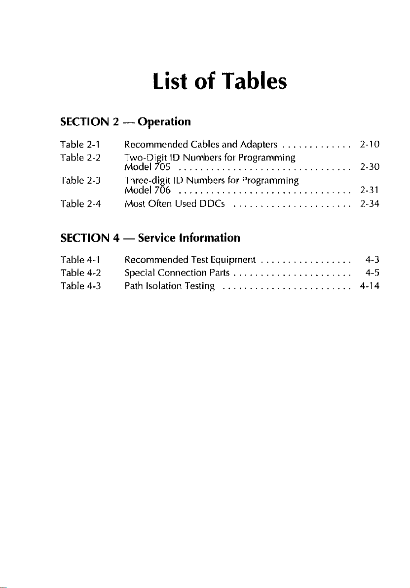
list of Tables
SECTION 2 - Operation
Table 2-l Recommended Cables and Adapters
Table 2-2
Table 2-3 Three-digit ID Numbers for Programming
Table 2-4
Two-Digit ID Numbers for Programming
Model705
Model706
Most Often Used DDCs
2.10
Z-30
2.31
2-34
SECTION 4 - Service Information
Table 4-l
Table 4-2 Special Connection Parts ......................
Table 4-3 Path isolation 1.esting ........................ 4-14
Recommended Test Equipment ................. 4-3
4-5
Page 15

SECTION 1 General Information
1 .l INTRODUCTION
This section contains general information about the Model 7153 High
Voltage Low Current Matrix Card and is arranged as follows:
1.2 Features
1.3 Warranty Information
1.4 Manual Addenda
1.5 Safety Symbols and Terms
1.6 Specifications
1.7 Unpacking and Inspection
1.8 Repacking for Shipment
1.9 Optional Accessories
1.2 FEATURES
Key features of the Model 7153 High Voltage Low Current Matrix Card in-
clude:
. 4 x 5 (four row by five column) switching matrix.
l
Low offset current for low-current measurements.
1-1
Page 16

SECTION 1
General
Information
1.3 WARRANTY INFORMATION
Warranty information is located on the inside front coverofthis instruction
manual. Should your Model 7153 require warranty service, contact the
Keithley representative or authorized repair facility in your area for further
information. When returning the matrix card for repair, be sure to fill out
and include the service form at the back of this manual in order to provide
the repair facility with the necessary information.
1.4 MANUAL ADDENDA
Any improvements or changes concerning the matrix card or manual will
be explained in an addendum included with the the unit. Be sure to note
these changes and incorporate them into the manual before using or serv-
icing the unit.
1.5 SAFETY SYMBOLS AND TERMS
The following symbols and terms may be found on an instrument or used
in this manual.
The A
the operating instructions located in the instruction manual.
The
sent on the terminal(s). Use standard safety precautions to avoid personal
contact with these voltages.
The WARNING heading used in this manual explains dangers that might
result in personal injury or death. Always read the associated information
carefully before performing the indicated procedure.
The CAUTION heading used in this manual explains hazards that could
damage the matrix card. Such damage may invalidate the warranty.
1-2
symbol on an instrument indicates that the user should refer to
symbol on an instrument shows that 1 kV or greater may be pre-
i
Page 17

General Information
SECTION 1
1.6 SPECIFICATIONS
Model 7153 specifications are located at the front of this manual. These
specifications are exclusive of the mainframe specifications, which are located in their respective instruction manuals.
1.7 UNPACKING AND INSPECTION
1.7.1 Inspection for Damage
Upon receiving the Model 7153, carefully unpack it from its shipping carton and inspect the card for any obvious signs of physical damage. Report
any such damage to the shipping agent immediately. Save the original
packing carton for possible future reshipment.
1.72 Shipment Contents
The following items are included with every Model 7153 order:
. Model 7153 Iiigh Voltage Low Current Matrix Card.
. Model 7153 Instruction Manual.
. Additional accessories as ordered.
1.7.3
If an additional instruction manual is required, order the manual package,
Keithley part number 7153-901-00. The manual package includes an in-
struction manual and any pertinent addenda.
Additional Instruction Manual
1.8 REPACKING FOR SHIPMENT
Should it become necessary to return the Model 7153 for repair, carefully
pack the unit in its original packing carton or the equivalent, and include
the following information:
. Advise as to the warranty status of the matrix card.
l-3
Page 18

SECTION 1
General Information
l
Write ATTENTION REPAIR DEPARTMENT on the shipping label.
. Fill out and include the service form located at the back ofthis manual.
1.9 OPTIONAL CABLE ASSEMBLY
The following cable assembly is available to make connections to the
Model 7153.
Model 7153-TRX - This 2-meter cable assembly is made up of five individual triax cables. One end of the cable assembly is terminated with a
miniature, multiple-contact plug that will mate to the matrix card receptacles. The other end of the cable assembly is terminated with five 3.slot
male triax connectors.
NOTE
Adapters that are available from Keithley are listed in Table
2-1.
l-4
Page 19

SECTION 2 Operation
2.1 INTRODUCTION
This section contains information on aspects of matrix card operation and
is arranged as follows:
2.2 Handling Precautions: Details precautions that should be observed
when handling the matrix card to ensure that its performance is not de-
graded due to contamination.
2.3 Environmental Considerations: Outlines environmental aspects of
using the Model 7153.
2.4 Equivalent Circuit: Provides the simplified matrixcard circuitforthe
Model 7153.
2.5 Card Installation and Removal: Covers the basic procedures for installing and removing the matrix card from the Model 705 or 706 main-
frame.
2.6 Connections: Discusses card connectors, cables and adapters, and
typical connections to other instrumentation and DUT test fixtures.
2.7 Matrix Expansion: Shows how to expand the matrix by connecting
two or more matrix cards together.
2.8 Mainframe Control of Matrix Card: Covers the operating aspects
specific to the Model 71 S3.
2.9 Measurement Considerations: Reviews a number of considerations
when making low-level measurements.
2-1
Page 20

SECTION 2
Operation
2.2 HANDLING PRECAUTIONS
To maintain high impedance isolation, care should be taken when handling the matrix card to avoid contamination from such foreign materials
as body oils. Such contamination can substantially lower leakage resistances, degrading performance.
To avoid possible contamination, always grasp the card by the side edges.
Do not touch the edge connectors of the card and do not touch board surfaces or components. When not installed in a mainframe, keep the card in
the bag and store in the original packing carton.
Dirt build-up over a period of time is another possible source of contamination. To avoid this problem, operatethe mainframe and matrix card only
in a clean environment.
If the card should become contaminated, it should be thoroughly cleaned
as explained in paragraph 4.2.
2.3 ENVIRONMENTAL CONSIDERATIONS
For rated performance, the card should be operated within the temperature and humidity limits given in the specifications at the front of this manual. Note that current offset and path isolation values are specified within a
lower range of limits than the general operating environment.
2.4 EQUIVALENT CIRCUIT
A simplified schematic of the Model 7153 4 x 5 matrix card is shown in
Figure 2-I. Each ofthe 20 crosspoints is made up of a two-pole switch. In
this simple configuration any row can be connected to any column by
closing the appropriate crosspoint. Mainframe control of matrix
crosspoints is covered in paragraph 2.8.
2-2
Page 21

SECTION 2
Operation
rI
I
I
I
1)
I
I
2>
’ now
3>
I
4)
I
I
I
I
I--
Figure 2-1. SchematicofModel7753
-
A diagram of the Model 7153 is provided in Appendix A. This
system configuration worksheet makes it convenient to plan a
matrix system. Additional space is provided for drawings and
notes.
__--------
Column
1 2 3 4 5
“2
97
NOTE
-1
I
I
I
I
I
I
I
I
I
I
I
I
I
- _I
2.5 CARD INSTALLATION AND REMOVAL
The following procedures explain how to install and remove the Model
7153 matrix card from the Models 705 and 706 mainframes.
WARNING
To prevent electrical shock which could result in injury or
death, turn off the mainframe power and disconnect the line
cord before installing or removing matrix cards. If there are
2-3
Page 22

SECTION 2
Ooeration
cables connected to the card, also remove power from those
circuits before proceeding.
CAUTION
Contamination will degrade the performance of the matrix
card. To avoid contamination, always grasp the card by the
side edges. Do not touch the board surfaces or components.
2.5.1
Perform the following procedure to install the Model 7153 Imatrix card in
either the Model 705 or Model 706 mainframe. Refer to Figure 2-2 to install the card in the Model 705 and refer to Figure 2-3 to install the card in
the Model 706.
1.
2.
3.
Matrix Card Installation
Slidethe card into the desired slot as shown in the appropriate illustra-
tion. Make surethe card edges ofthe bottom shield board are properly
aligned with the grooves in the receptacle.
Once the card is almost all the way in the slot, and you encounter resistance, push firmly on the edge of the card to seat it in the edge connector.
Once the card is fully seated, lock the card in place by placing the
latches in the locked position.
2-4
Page 23

SECTION 2
ODeration
Figure 2-2. Card lnstahtion in a Model 705
-
2-5
Page 24

SECTION 2
Operation
‘igure 2-3.
2.5.2
To remove the matrix card, first unlock it by pulling the latches outward,
then grasp the end of the card at the edges, and pull the card out of the
mainframe.
2.6
The information in the following paragraph explains how to connect the
matrix card to external test circuitry (instruments and DUTL
2-6
INSTRUMENT AND DUT CONNECTIONS
Card hstaallation in a Model 706
Matrix Card Removal
Page 25

SECTION 2
Operation
CAUTION
Do not connect the matrix card to unlimited power circuits.
This product is intended for use with impedance limited
sources. Do not connect directly to AC mains.
When connecting an impedance limited source, install appropriate protection (such as a fuse or a clamping circuit) to limit
potentially damaging fault currents to the matrix card.
CAUTION
Contamination will degrade the performance of the matrix
card. To avoid contamination, always grasp the card by the
side edges. Do not touch the board surfaces or components.
Card connectors, recommended cables and adapters, and typical connections to instruments and DUT are discussed in the following paragraphs.
2.6.1 Card Connectors
The card connectors are shown in Figure 2-4. There are two miniature coaxial, multiple contact receptacles. One ofthe receptacles is used for row
connections and the other is used for column connections. Row and column number designations are included in the illustration. Notice that one
contact of each receptacle is reserved for chassis ground. For each coaxial
connector, as shown in Figure 2-5, the center conductor is SIGNAL, and
the outer shell (shield Iis GUARD.
2-7
Page 26

SECTION 2
Operation
Note : Numbers indicate row and column paths.
Tzure 2-4. Model 7753 Connectors
&;a.;”
Max
Chassis Ground Connector
(1 Of 2)
IL----!
Warning : Do not exceed maximum
voltage levels shown.
t ‘igure 2-5. Miniature Connector Configuration
2-8
13oov
Max
Page 27

SECTION 2
Operation
WARNING
Do not exceed 200V behveen SIGNAL and GUARD, or 13OOV
between SIGNAL and chassis ground, or behveen GUARD
and chassis ground or between paths (see Figure 2-5). Also,
do not exceed IA carry/500mA switched, 1OVA peak (resistive load).
CAUTION
To prevent damage to the matrix card and other equipment,
do not connect equipment such that they short out on the
same row or column.
2.6.2 Recommended Cables and Adapters
Table 2-1 summarizes the cables and adapters recommended for use with
the Model 7153.
NOTE
Equivalent user-supplied items may be substituted as long as
they are of sufficient quality (low offset current, high leakage
resistance). Using substandard cables and adapters may degrade the integrity of the measurements made using the matrix
card. See paragraph 2.9 for a discussion of measurement considerations.
The following discussion provides additional information about the recommended Keithley cable; Model 7153.TRX cable.
2-9
Page 28

SECTION 2
Operation
Table 2-l. Recommended Cables and Adapters
Manufac-
tern
turer
1
Keithley
2
Keithley 6172
Keithley
Keithley 237-TRX-T
Keithley
Model or
Part No.
7153.TRX
237~BAN-3
Descriotion Applications
Matrix to triax
cable put connections
2.slot male to
3-lug female
triax adapter
3-14 female
to female triax
barrel male triax cable
3-&t male to
dual 3-lug tions for
female
3-slot triax to
male banana
plup
‘6172 is for use in low voltage kC5OOVrms) applications only.
7153 input/out-
Connect 3-slot
triax cable to
2-1~~ triax connector
Connect male
triax cable to
Dual connec-
7153.TRX
Banana plug cable
Model 7153-TRX Low Noise Matrix to Triax Cable
TheModel 7153-TRX is a 2-m&r cableassembly that is terminated with a
miniature coaxial, multiple contact plug at one end, and five 3-slot male
triax connectorsat the other end. The plug end of the cable will mate to the
ROW and COL receptacles of the matrix card. The triax connectors will
mate to standard 3-lug female triax connectors. Each triax cable is labeled
and corresponds to a ROW or COL as follows:
2-10
Page 29

SECTION 2
Operation
Triax #II = Row 1 or Column 1
Triax #t2 = Row 2 or Column 2
Triax lt3 = Row 3 or Column 3
Triax $14 = Row 4 or Column 4
Triax +#5 = Column 5
On each triax connector, as shown in Figure 2-7, the center conductor is
SIGNAL, the inner shield is GUARD, and the connector shell is connected
to the outer shield of the cable. Note that this outer shield is connected to
chassis of the Model 7153.
Pill designations
molded on plug
housing
Pill
Designation
1
F
Figure 2.6.
-
Matrix Card
ROW or Column
Model 7753.TRX Pin
Note : Pin designations 1, 2. 4. 5 and 6
iv3 coaxial co”“octor~. Pill 3 is
a s,nc$e ,,I” connector for chassis
ground.
identification
2-11
Page 30

SECTION 2
Ooeration
Signal
7153
Chassis
Ground
Warning : Do not exceed maximum
voltage levels shown.
Figure 2-7. Trim Connector Configuration (Model 71.53-TRN
2.6.3
The following paragraphs discuss connecting the Model 7153 to various
general classes of instrumentation such as DMMs, electrometers, sources,
and source/measure units. Because these configurations are generic in nature, some modification of the connecting schemes may be necessary for
your particular instrumentation. Also, special cables or adapters may be
necessary.
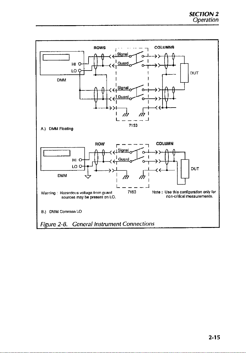
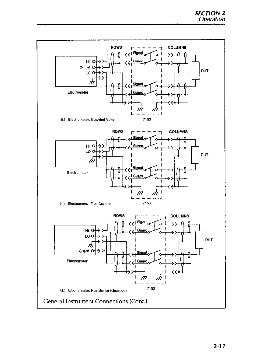
Figure 2-8 shows the general instrument connections for the discussions
below. Note that DUT guarding or shielding is not indicated here; see
Figure 2-18 and Figure 2-21 for shielding and guarding information. As
shown, all figures assume instruments are connected to rows, and the DUT
is connected to columns.
General Instrument Connections
WARNING
Do not use coaxial cables and adapters because hazardous
voltage from guard sources may be present on the cable
shields.
2-12
Page 31

SECTION 2
Ooeration
DMM Connections
General DMM connections are shown in Figure 2-13(A), @I, and (Cl. Floating connections are shown in (A), with LO and HI routed to two separate
rows on the Model 7153. The common LO connections in (5) should be
used only for non-critical applications becausethe performance (isolation)
of the GUARD pathway is not as good as a SIGNAL pathway.
WARNING
Hazardous voltage from other guard sources may be present
on LO or the DUT if other crosspoints are closed.
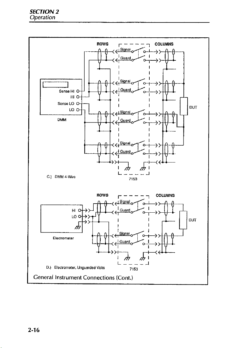
Four-wire DMM connections are shown in Figure 2-K). In this case, a total of four rows are required; one row for HI, one for LO, one for SENSE HI,
and one for SENSE LO.
Electrometer Connections
Typical electrometer connections are shown in Figure 2-8(D) through (G).
The unguarded volts connections in (Dl show the HI signal path routed to
one row, and the LO path goes to a another row. Both GUARD pathways
are connected to electrometer LO. For guarded voltage (E), Model 7153
GUARD is connected to electrometer GUARD.
The connections for electrometer fast amps and resistance measurements
are shown in Figure 2-8(F) and (CL These configurations are essentially the
same as those discussed above. In the case of fast amps, both GUARD
paths are connected to electrometer LO, while in the case of guarded resistance, one GUARD path is connected to electrometer GUARD, and the
other GUARD path is connected to electrometer LO.
Source Connections
Voltage and current source connections are shown in Figure 2-O(H)
through (J). The HI and LO paths of the voltage source (H) are routed
through two rows, with both card GUARD pathways connected to voltage
source LO. For the unguarded current source connections (I), card
2-13
Page 32
SECTION 2
Oneration
GUARD is again connected to source LO, with source HI and LO routed
through two rows. In the case of the guarded current source in (I), card
GUARD of the HI signal path is connected to source GUARD, and the
other GUARD path is connected to source LO.
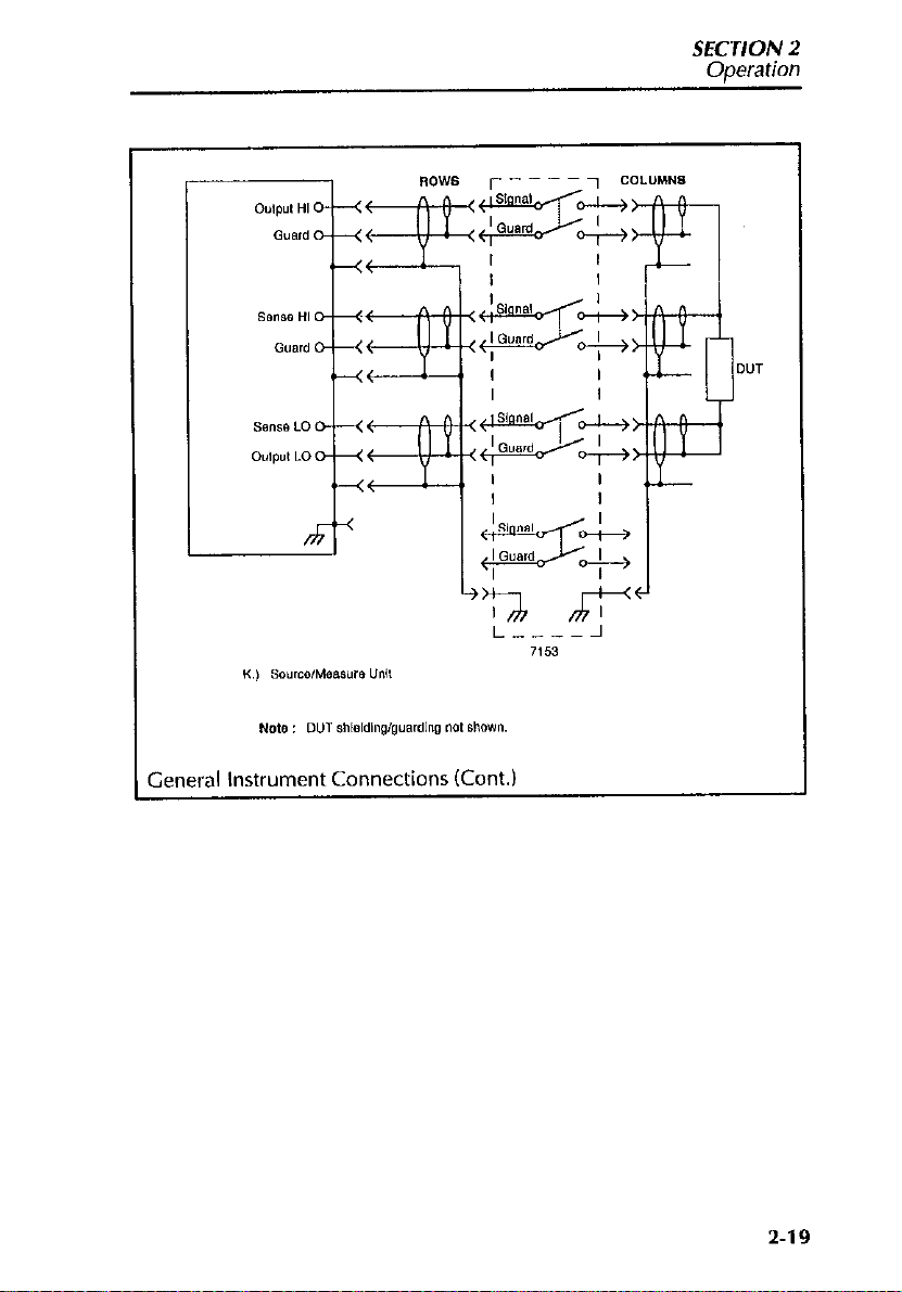
Source/Measure Unit Connections
Figure 2-8(K) shows typical connections for a source/measure unit (SMU).
In this instance, a remote-sensing type of a SMU is shown, requiring a total
of four signal pathways to the DUT. For critical measurements, both
source and sense HI pathways would be guarded as shown, with two of the
four card GUARD pathways connected to SMU GUARD terminals. As
with other instrument connections, the LO card GUARD pathways are
connected to SMU LO terminals.
2-14
Page 33
SECTION 2
Ooeration
2-15
Page 34
SECTION 2
Operation
General Instrument Connections (Cont.)
2-16
Page 35
I/h /?!I
i----J
G., Elecmnelei, ReSlslanCB (Guarded)
General Instrument Connections (Cont.)
x63
2-17
Page 36

SECTION 2
Operation
2-l 8
Page 37
SECTION 2
Operation
2-19
Page 38

SECTION 2
Operation
2.6.4 Keithley Instrument Connections
The foollowing paragraphs outline connecting typical Keithley instruments
to the Model 7153 High Voltage Low Current Matrix Card. Other similar
instruments can be connected using the same cabling as long as their input/output configurations are the same. Instrument connections covered
include:
. Model 617 Electrometer/Source
. Model 237 High Voltage Source Measure Unit
. Model 230 Programmable Voltage Source
l
Model 220 Programmable Current Source
NOTE
The following figures show instruments connected to matrix
rows. Keep in mind that they could just as well be connected to
matrix columns. Also, it doesn’t matter which rows (or columns) are used since the row/column specifications are uniform.
WARNING
To
prevent
not
apply power
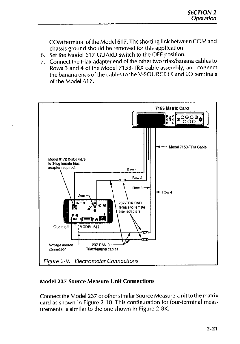
Model 617 Electrometer Connections
Connections for the Model 617 Electrometer are shown in Figure 2-9 and
are described as follows:
1, Connect the matrix end of the Model 7153-TRX cable assembly to
ROW of the Model 7153.
2. Connect the Model 6172 2-slot male to 3-lug female triaxial adapter
to the INPUT of the Model 617.
3. Connect Row 1 of the Model 7153.TRX cable assembly to the triax
adapter on the INPUT of the Model 617.
4. Connect three 3-lug female to female triax adapters (item 3 in
Table 2-l) to the three t&x/banana cables (Model 237-BAN-3)..
5. Connect the triax adapter end of a triax/banana cable to Row 2 of the
Model 7153-TRX, and connect the banana end of the cable to the
Z-20
electric shock that could cause injury or death, do
to cables that are not connected.
Page 39
SECTION 2
Oneration
COM terminal oftheModel617,Theshorting IinkbetweenCOM and
chassis ground should be removed for this application.
6. Set the Model 617 GUARD switch to the OFF position.
7. Connect the triax adapter end of the other two triaxfbanana cables to
Rows 3 and 4 of the Model 7153.TRX cable assembly, and connect
the banana ends of the cables to the V-SOURCE l-11 and LO terminals
of the Model 617
Figure 2-9. Electrometer Connections
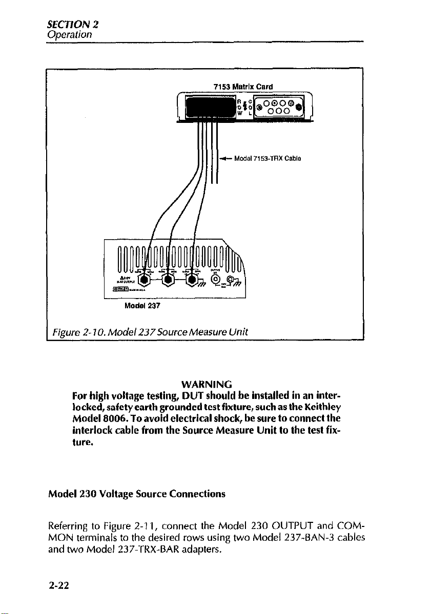
Model 237 Source Measure Unit Connections
Connectthe Model 237 orothersimilar Source Measure Unit to the matrix
card as shown in Figure 2-10. This configuration for four-terminal measurements is similar to the one shown in Figure 2-8K.
2-21
Page 40
SECTION 2
Operation
Figure 2- 10. Model 237Source Measure Unit
WARNING
For high voltage testing, DUT should be installed in an interlocked, safety earth grounded test fixture, such as the Keithley
Model 8006. To avoid electrical shock, be sure to connect the
interlock cable from the Source Measure Unit to the test fix-
ture.
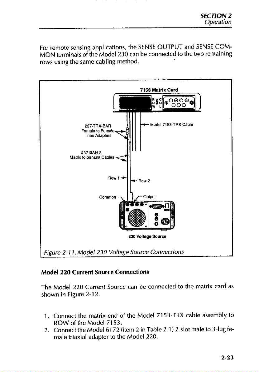
Model 230 Voltage Source Connections
Referring to Figure 2-I 1, connect the Model 230 OUTPUT and COMMON terminals to the desired rows using two Model 237-BAN-3 cables
and two Model 237.TRX-BAR adapters.
2.22
Page 41
SECTION 2
Operation
For remote sensing applications, the SENSE OUTPUT and SENSE COMMON terminals of the Model 230 can be connected to the two remaining
rows using the same cabling method.
0gure 2- 11. Model 230 Voltage Source Connections
Model 220 Current Source Connections
The Model 220 Current Source can be connected to the matrix card as
shown in Figure 2-12.
1, Connect the matrix end of the Model 7153-TRX cable assembly to
ROW of the Model 7153.
2. Connect the Model 6172 (item 2 in Table 2-l )2-slot male to 3.lug fe-
male triaxial adapter to the Model 220.
2-23
Page 42

SECTION 2
Operation
Figure 2- 12. Mode/ 220 Current Source Connections
3. Connect Row 1 of the Model 7153-TRX cable assembly to the 6172
triax adapter.
4. Connect a 3-lug female to female triax adapter to the G&banana ca-
ble.
5. Connect the triax adapter end of the triadbanana cable to Row 2 of
the Model 7153-TRX, and connect the banana end of the cable to the
OUTPUT COMMON jack of the Model 220.
NOTE
,The configuration shown allows common to be individually
switchec i (ROW 2). Thus, do not connect ROW1 Guard of the
matrix card (which is also common) to a DUT.
2-24
Page 43

SECTION 2
Ooeration
2.6.5 Typical Test Fixture Connections
Typically, a test fixture will be connected to desired columns of the Model
7153. Normally, the test fixture will be equipped with 3&g female triax
connectors to facilitate the use of the Model 7153.TRX cable assembly.
These typical test fixture connections are shown in Figure 2-13
Figure 2- 13. Typical
Do not use BNC cables and adapters because hazardous voltages from guard sources could be present on the BNC cable
shields.
Internally, the test fixture should be wired as shown in the equivalent circuit of Figure 2-14. SIGNAL isconnected totheprobeorotherdevicecon-
tact points, while GUARD is carried through as close to the device as pos-
sible. If coaxial probes are to be used, connect GUARD to the probe shield
if the probe shield is insulated from the fixture shield.
To provide protection from shock hazards, the test fixture
chassis must be properly connected to a safety earth ground.
A grounding wire (IO AWC or larger) must be attached se-
curely to the test fixture at a terminal designed for safety
rounding (the terminal should be marked with the symbol
& ). The other end of the grounding wire is then attached to a
8
Jest
Fixhire Connecrions
WARNING
WARNING
2-25
Page 44

known safety earth ground, such as a cold water pipe, or a
grounded electrical outlet box.
Figure 2-14.
Equivalent
Circuit of Test Fixture Connections
2.7 MATRIX EXPANSION
A matrix can be expanded by connecting two or more Model 7153 matrix
cards together. A single matrix card consists of 20 crosspoints. Thus, each
additional matrix card increases the matrix by 20 crosspoints. Connecting
the rows or one matrix card to the rows of another matrix card increases
thenumberofmatrixcolumns.Connectingthecolumnsofonematrixcard
to the columns of another matrix card increases the number of matrix
rows.
Matrix Expansion Connections
Model 7153.TRX cables along with the appropriate adapters can be used
for matrix expansion. Typical row connections of two matrix cards (which
will increase the available matrix columns to IO) are shown in Figure 2-l 5.
The rows of the two matrix cards are connected togehter via four Model
237-TRX-T adapters. The Model 237-TRX is a high voltage 3-&t male
triax to dual 3-lug female triax adapter. Standard 3-slot triax cables (such
as the Model 7078.TRX) from the instrumentation or DUT test fixture will
2-26
Page 45

SECTION 2
Ooeration
mate to the male end of the 9”’ adapters via four Model 237-TRX-BAR
adapters.
To connect the rows of more matrix cards, simply use additional Model
237-TRX-T adapters. Each additional matrix card will require four “T”
adapters.
Column connections, which increase matrix rows, are made in a similar
fashion. The only difference is that the Model 7153.TRX cables are instead
connected to the COL connectors on the matrix card.
Figure 2-15. Typical Row Connections for Matrix Column Expansion
2-27
Page 46

SECTION 2
Operation
2.8 MAINFRAME CONTROL OF MATRIX CARD
The information in the following paragraphs does not includeoperation of
the Model 705 or 706 mainframe. That information is provided in the respective mainframe instruction manuals. The following deals primarily
with programming information specific to controlling the Model 7153.
Whether from the front panel or over the IEEE-498 bus, matrix control is
simply a matter ofclosing and opening the appropriate matrix crosspoints.
Crosspoint assignment numbers for a Model 7153 card are determined by
its installed position (card number) in a mainframe. For daisy chain operation, the position of the mainframe in the system is also a determining factor. The following paragraphs explain how to determine crosspoint assign-
ment numbers.
2.8.1 Front Panel Matrix Control
Using the Model 7153 matrix card with an appropriate Keithley mainframe (Model 705 or 706) requires that the matrix mode be selected. To
place the mainframe in the matrix mode from the front panel, perform the
following steps:
1. Select Program 6 by pressing the PRCM key and then the number 6
key.
2. Press the 0 key and then the ENTER key.
After the ENTER key is pressed, the mainframe is placed in the matrix mode
of operation.
With the mainframe in the matrix mode, the display format is as follows:
For the Model 705:
mmnx
where: “mm n” is the crosspoint assignment number.
2-28
Page 47

SECTION 2
Operation
mm = 2-digit ID number from 01 to 50. This number identifies the mainframe and slot that the card is located in and also indicates the matrix card
column number.
n = Matrix card row from 1 to 4.
x denotes the status of the crosspoint. An 0 indicates that the crosspoint is
open, while a C indicates that the crosspoint is closed.
For the Model 706:
mmmnx
where: “mmm n” is the crosspoint assignment number
mmm = 3-digit ID number from 001 to 250. This number identifies the
mainframe and slot that the card is located in and also indicates the matrix
card column number.
n = Matrix card row from 1 to 4
x denotes the status of the crosspoint. An 0 indicates that the crosspoint is
open, while a C indicates that the crosspoint is closed.
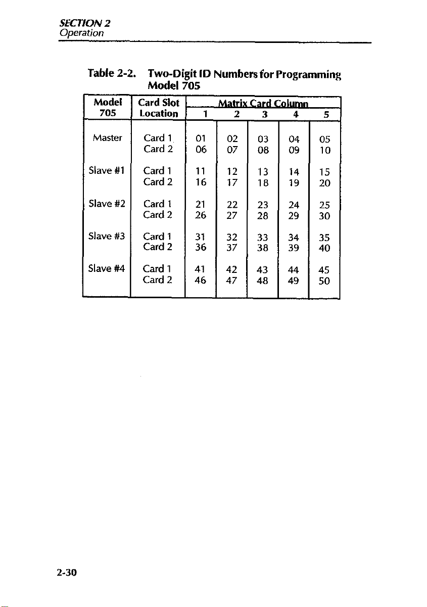
In general, controlling the matrix from the front panel consists of display-
ing the desired matrix crosspointassignment number and closing (or open-
ing) the crosspoint relay. Table 2-2 and Table 2-3 provide the two-digit
(for Model 705) and three-digit (for Model 706) ID numbers that make up
the “m” portion of the crosspoint assignment number.
2-29
Page 48
SECTION 2
Operation
Table 2-2. Two-Digit ID Numbers for Programming
Model 705
Model
705
Card Slot
Location
Master
Slave #1
Slave #2
Slave #3
Slave #4
Card 1 01
Card 2 06
Card 1 11
Card 2 16
Card 1 21
Card 2 26
Card 1 31
Card 2 36
Card 1 41
Card 2 46 47
I
-
02
07
12
17
22
27
32 33
37
42
03
08 09
13
18 19
23
28
38
43
48
04
14
24
29
34
39
44
49
05
10
15
20
2s
30
35
40
45
50
2-30
Page 49

SECTION 2
Oaeration
Table 2-3. Three-dieit ID Numbers for Proeramminc!
Model 766
Model
706
Master
&we #l
;lave #2
Card Slot
location
Card 1
Card 2 006 007 008 009 010
Card 3 011 012 013 014 015
Card 4 016 017 018
Card 5
Card 6
Card 7
Card 8 036 037 038 039 040
Card 9
Card 10
Card 1 051 052
Card 2 056 057 058
Card 3
Card 4
Card 5 071 072 073
Card 6 076 077 078
Card 7 081
Card 8
card Y 091 092 093 094
Card10 096 097 098 099 100
Card 1
Card 2
Card 3
Card 4
Card 5
Card 6
Card 7
Card 8
Card 9
Card 10
Mat&&,&&Cardn
1 2 3
001 002 003 004 005
019 020
021 022 023 024 025
026
031 032 033 034 035
041
046 047 048 049 050
061 062 063 064 065
066
086 087 088 089 090
101 102
106 107
111 112
116 117
121 122
126
131 132
136 137
141 142
146 147
- -
027
042
067
082 083 084 085
127
028 029 030
043 044 045
053 054 055
059 060
068 069 070
074 075
079 080
103
108
113
118
123
128
133
138
143
148
-
104
109 110
114
119
124
129 130
134 135
139 140
144
149 150
- - L
5
095
105
115
120
125
145
2-31
Page 50
SECTION 2
Operation
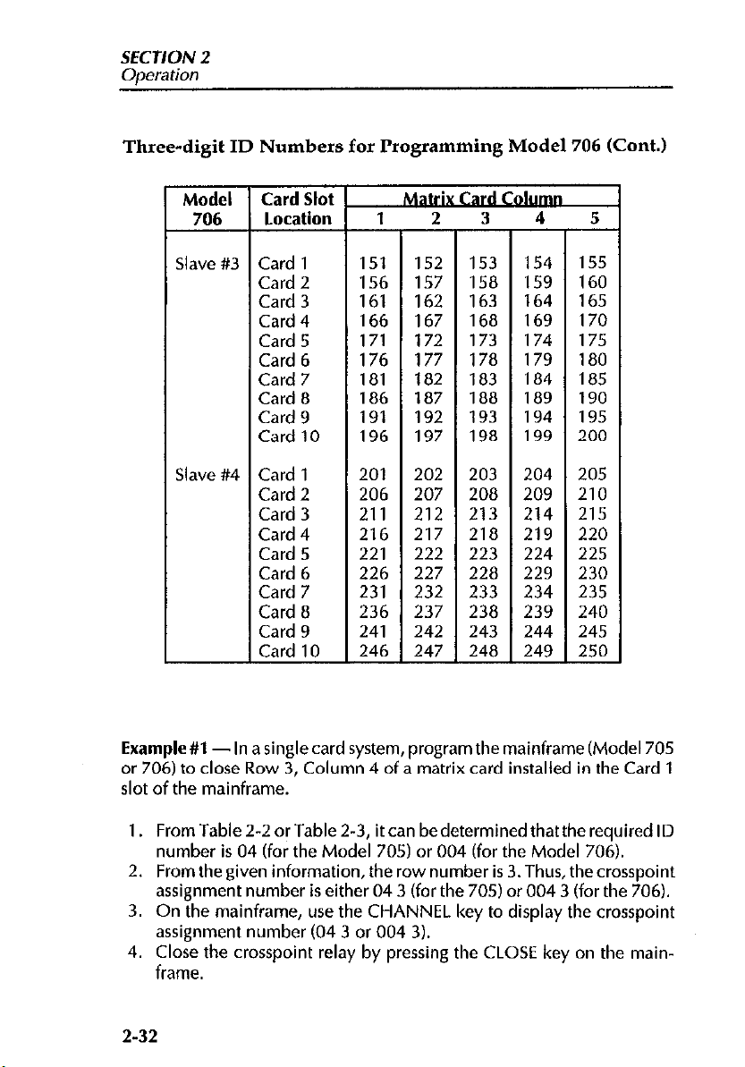
Three-digit ID Numbers for Programming Model 706 (Cont.)
Model
706
ilave #3
ilave #4
Card Slot
T
Location
Card 1
Card 2
Card 3
Card 4
Card 5
Card 6
Card 7
Card 8
Card 9
Card 10
Card 1
Card 2
Card 3
Card 4
Card 5
Card 6
Card 7
Card 8
Card 9
Card 10
151 152 153 154
156
161 162 163
166 167 168
171 172
176 177 178
181 182 183 184
186 187 188 189
191 192 193
196 197 198
201 202 203 204
206 207 208 209
211 212 213 214
216
221 222 223 224
226 227 228
231 232 233 234
236 237
241 242 243 244
246
- - - -
157 158 159
164
169
173 174
179
194
199
217 218 219
229
238
247 248 249
239
155
160
165
170
175
180
185
190
195
200
205
210
215
220
225
230
235
240
245
250
-
Example #l -In a single card system, program the mainframe (Model 705
or 706) to close Row 3, Column 4 of a matrix card installed in the Card 1
slot of the mainframe.
1. From Table 2-2 or Table 2-3, it can be determined that the required ID
number is 04 (for the Model 705) or 004 (for the Model 706).
2. From the given information, the row number is 3. Thus, thecrosspoint
assignment number is either 04 3 (for the 705) or 004 3 (for the 706).
3. On the mainframe, use the CHANNEL key to display the crosspoint
assignment number (04 3 or 004 3).
4. Close the crosspoint relay by pressing the CLOSE key on the mainframe.
2-32
Page 51
SECTION 2
Ooeration
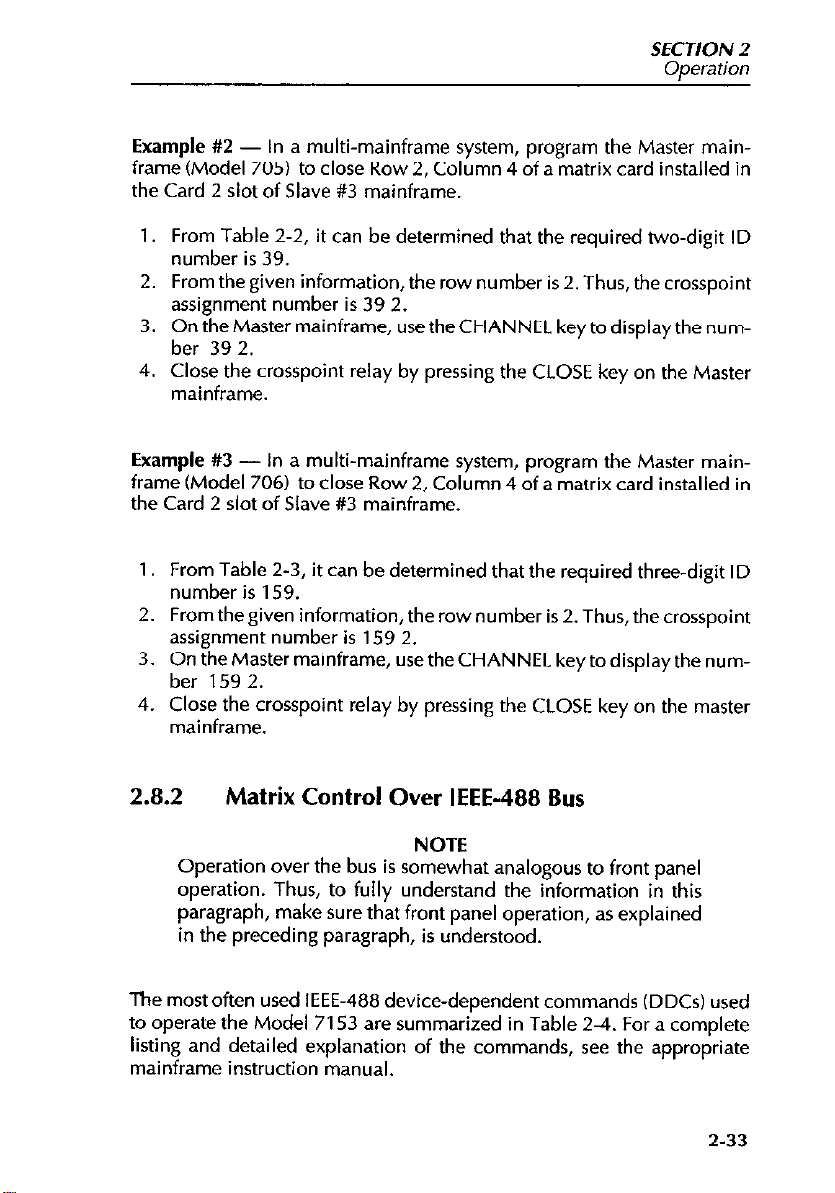
Example #2 - In a multi-mainframe system, program the Master mainframe (Model 705) to close Row 2, Column 4 of a matrix card installed in
the Card 2 slot of Slave #3 mainframe.
1. From Table 2.2, it can be determined that the required two-digit ID
number is 39.
2. From the given information, the row number is 2. Thus, the crosspoint
assignment number is 39 2.
3. On the Master mainframe, use the CHANNEL key to display the number 39 2.
4. Close the crosspoint relay by pressing the CLOSE key on the Master
mainframe.
Example #3 - In a multi-mainframe system, program the Master mainframe (Model 706) to close Row2, Column 4 of a matrix card installed in
the Card 2 slot of Slave #3 mainframe.
1. From Table 2-3, it can be determined that the required three-digit ID
number is 159.
2. From the given information, the row number is 2. Thus, the crosspoint
assignment number is 159 2.
3. On the Master mainframe, use the CHANNEL key to display the number 159 2.
4. Close the crosspoint relay by pressing the CLOSE key on the master
mainframe.
2.8.2
The most often used IEEE-488 device-dependent commands (DDCs) used
to operate the Model 7153 are summarized in Table 2-4. For a complete
listing and detailed explanation of the commands, see the appropriate
mainframe instruction manual.
Matrix Control Over IEEE-488 Bus
NOTE
Operation over the bus is somewhat analogous to front panel
operation. Thus, to fully understand the information in this
paragraph, make sure that front panel operation, as explained
in the preceding paragraph, is understood.
2-33
Page 52
SECTION 2
Ooeration
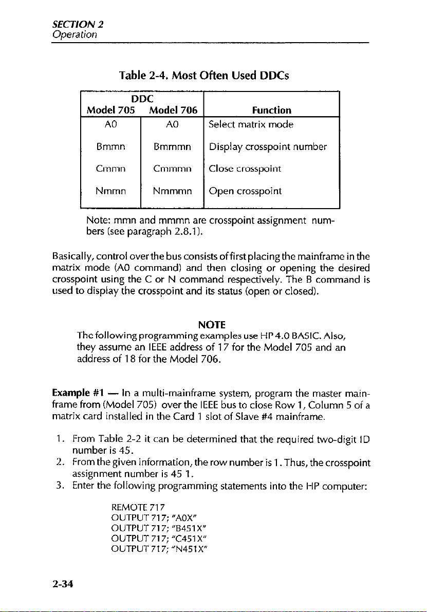
Table 2-4. Most Often Used DDCs
Function
Select matrix mode
Bmmn Bmmmn
Cmmn Cmmmn
Nmmn Nmmmn
L-L
Note: mmn and mmmn are crosspoint assignment numbers (see paragraph 2.8.1).
Basically, control over the bus consists offirst placing the mainframe in the
matrix mode (A0 command) and then closing or opening the desired
crosspoint using the C or N command respectively. The B command is
used to display the crosspoint and its status (open or closed).
Thefollowingprogrammingexamples use HP4.0 BASIC. Also, Thefollowingprogrammingexamples use HP4.0 BASIC. Also,
they assume an IEEE address of 17 for the Model 705 and an they assume an IEEE address of 17 for the Model 705 and an
address of 18 for the Model 706. address of 18 for the Model 706.
Example #l
frame from (Model 705) over the IEEE bus to close Row 1, Column 5 of a
matrix card installed in the Card 1 slot of Slave #4 mainframe.
1. From Table 2-2 it can be determined that the required two-digit ID
number is 45.
From the given information, the row number is 1. Thus, thecrosspoint
2.
assignment number is 45 1.
Enter the following programming statements into the HP computer:
3.
- In a multi-mainframe system, program the master main-
Display crosspoint number
Close crosspoint
Open crosspoint
I
NOTE NOTE
2-34
REMOTE
OUTPUT 717: “AOX”
OUTPUT
OUTPUT 717; “C451 X”
OUTPUT 717; “N45, X”
717
717: “6451 X”
Page 53

SECTION 2
Operation
The second statement places the master Model 705 in the matrix mode.
The third statement displays crosspoint 45 1 and its current status (open or
closed). The fourth statement closes crosspoint 45 1, and the last statement
opens crosspoint 45 1.
Example
frame (Model 706) from over the IEEE bus to close Row 4, Column 1 of a
matrix card installed in the Card 8 slot of Slave #4 mainframe.
1. From Table 2-3 it can be determined that the required three-digit ID
2. From the given information, the row number is4. Thus, the crosspoint
3. Enter the following programming statements into the HP computer:
The second statement places the master Model 706 in the matrix mode.
The third statement displays crosspoint 236 4 and its current status (open
or closed). The fourth statement closes crosspoint 236 4, and the last state-
ment opens crosspoint 236 4.
2.9
Many measurements made with the Model 7153 concern low-level sig-
nals. Such measurements are subject to various types of noise that can seriously affect low-level measurement accuracy. The following paragraphs
discuss possible noise sources that might affect these measurements.
#2 - In a multi-mainframe system, program the master main-
number is 236.
assignment number is 236 4.
REMOTE 718
OUTPUT 718; “AOX”
OUTPUT 718; “82364X”
OUTPUT 718; %2364X”
OUTPUT 718; “N2364X”
MEASUREMENT CONSIDERATIONS
2.9.1
When a conductor cuts through magnetic lines of force, a very small voltage is generated. This phenomenon will frequently cause unwanted sig-
nalstooccurin thetest leadsofaswitchingmatrixsystem. Iftheconductor
Magnetic Fields
2-35
Page 54

SECTION 2
Operation
has sufficient length, even weak magnetic fields like those of the earth can
create sufficient signals to affect low-level measurements.
Two ways to reduce these effects are: (1) reduce the lengths of the test
leads, and (2) minimize the exposed circuit area. In extreme cases, magnetic shielding may be required. Special metals with high permeability at
low flux densities (such as mu metal) are effective at reducing these effects.
Even when the conductor is stationary, magnetically-induced signals may
still be a problem. Fields can be produced by various signals such as the
AC power line voltage. Large inductors such as power transformers can
generate substantial magnetic fields, so care must be taken to keep the
switching and measuring circuits a good distance away from these poten-
tial noise sources.
2.9.2 Radio Frequency Interference
RFI (Radio Frequency Interference) is ageneral term used to describe electromagnetic interference over a wide range of frequencies across the spectrum. Such RFI can be particularly troublesome at low signal levels, but
can also affect measurements at high levels if the problem is of sufficient
severity.
RFI can be caused by steady-state sources such as radio or TV signals, or
some types of electronic equipment (microprocessors, high speed digital
circuits, etc.), or it can result from impulse sources, as in the case of arcing
in high-voltage environments. In either case, the effect on the measure-
ment can be considerable if enough of the unwanted signal is present. A
common problem is the rectification by semiconductor junctions of RF
picked up by leads.
RFI can be minimized in several ways. The most obvious method is to keep
the equipment and signal leads as far away from the RFI source as possible.
Shielding the matrix switching card, signal leads, sources, and measuring
instruments will often reduce RFI to an acceptable level. In extreme cases,
a specially-constructed screen room may be required to sufficiently attenuate the troublesome signal.
2-36
Page 55
SECTION 2
Ooeration
Many instruments incorporate internal filteringthat may help to reduce RFI
effects in some situations. In some cases, additional external filtering may
also be required. Keep in mind, however, that filtering may have detrimental effects on the desired signal.
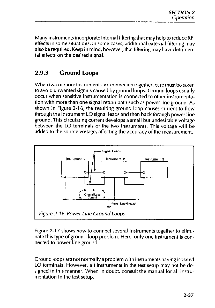
2.9.3
When two or more instruments are connected together, care must be taken
to avoid unwanted signals caused by ground loops. Ground loops usually
occur when sensitive instrumentation is connected to other instrumentation with more than one signal return path such as power line ground. As
shown in Figure 2-16, the resulting ground loop causes current to flow
through the instrument LO signal leads and then back through power line
ground. This circulating current develops a small but undesirable voltage
between the LO terminals of the two instruments. This voltage will be
added to the source voltage, affecting the accuracy of the measurement.
Ground Loops
Figure 2- 16. Power Line Ground Loops
Figure 2-17 shows how to connect several instruments together to eliminate this type of ground loop problem. Here, only one instrument is connected to power line ground.
Ground loops are not normally a problem with instruments having isolated
LO terminals. However, all instruments in the test setup may not be designed in this manner. When in doubt, consult the manual for all instrumentation in the test setup.
2-37
Page 56

SECTION 2
Operation
2.9.4 Keeping Connectors Clean
As is the case with any high-resistance device, the integrity of coaxial, triaxial and other connectors can be damaged if they are not handled properly. If the connector insulation becomes contaminated, the insulation resistance will besubstantially reduced, affecting high-impedance measurement paths.
Oils and salts from the skin can contaminate connector insulators, reduc-
ing their resistance. Also, contaminants present in the air can be deposited
on the insulator surface. To avoid these problems, never touch the connector insulating material. In addition, the matrix card should be used only in
clean, dry environments to avoid contamination.
If the connector insulators should become contaminated, either by inadvertent touching, or from air-borne deposits, they can be cleaned with a
cotton swab dipped in clean methanol. After thorough cleaning, they
should be allowed todryfor several hours in a low-humidity environment
before use, or they can be dried more quickly using dry nitrogen.
2-38
Page 57

SECTION 2
ODeration
2.9.5
Noise currents can be generated by bending or flexing coaxial or triaxial
cables. Such currents, which are known as triboelectric currents, are generated by charges created between a conductor and insulator caused by
friction,
Low-noise cable can be used to minimize these effects. Such cable has a
special graphite coating under the shield to provide lubrication and to provide a conduction path to equalize charges.
Even low-noise cable generates some noise currents when flexed or subjected to vibration. To minimize these effects, keep the cables as short as
possible, and do not subject them to temperature variations that could
cause expansion or contraction. Tie down offending cables securely to
avoid movement, and isolate or remove vibration sources such as motors
or pumps.
Noise Currents Caused by Cable Flexing
2.9.6 Shielding
Proper shielding ofall unguarded signal paths and devices under test is important to minimize noise pickup in virtually any switching matrix system.
Otherwise, interference from such noise sources as line frequency and RF
fields can seriously corrupt a measurement.
In order for shielding to be effective, the shield surrounding the HI signal
path should be connected to signal LO for chassis ground for instruments
without isolated LO terminals). Since most Model 7153 matrix applica-
tions call for separately switching LO, a separate connection from LO to
the cable shield at the source or measurement end must be provided, as in
the example of Figure 2-18. Here, we are using the GUARD path of the
Model 7153 to carry the shield out to the device under test. Needless to
say, this arrangement should not be used with guarding, as GUARD and
LO should not be connected together.
2-39
Page 58

SECTION 2
Ooeration
Figure Z- 10. Shielding Example
WARNING
Hazardous voltage may be present if LO on any instrument is
floated above ground potential.
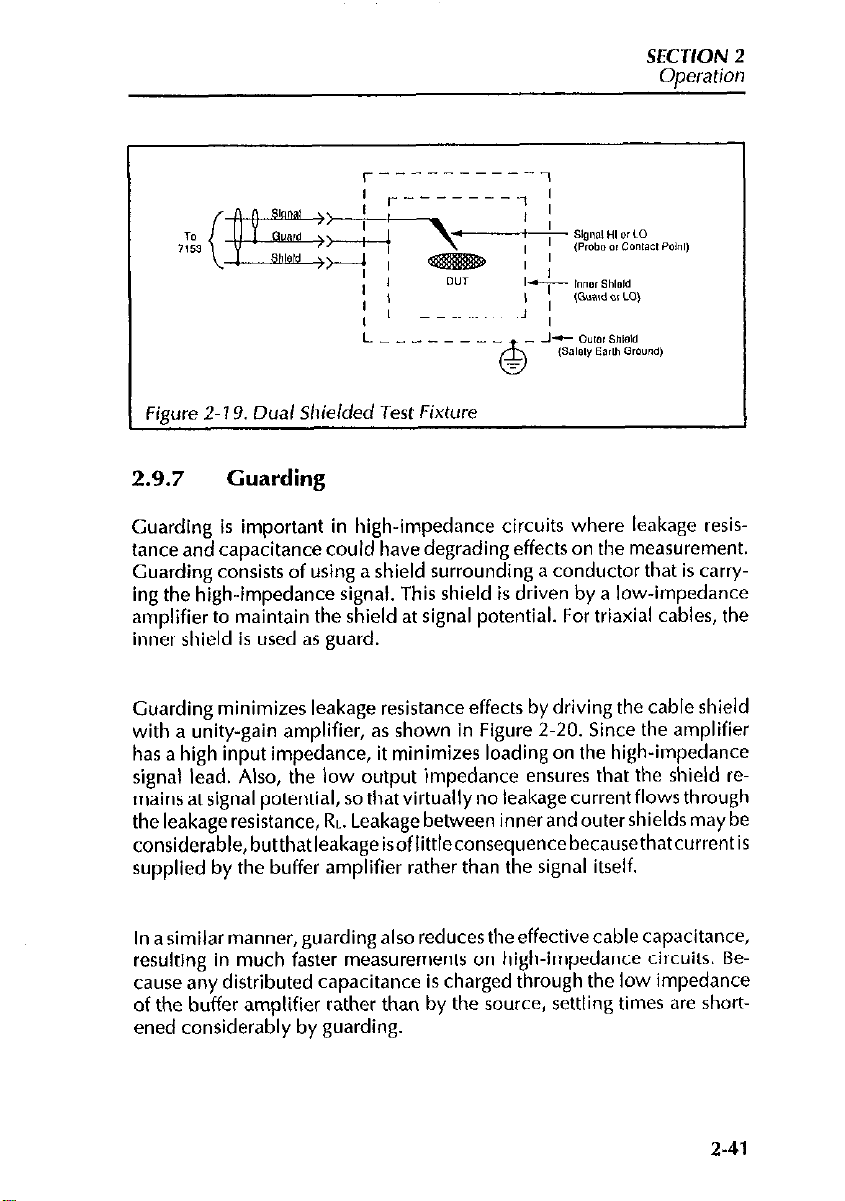
lfthe device under test is to be shielded, the shield should be connected to
the LO terminal. If you are using the GUARD connection as shield, care
should be taken to insulatethe outer ring ofthe triaxial connector mounted
on the test fixture from the test fixture itself. Otherwise, LO will be connected to earth ground, possibly resulting in a ground loop. An alternative
is to use two shields, one mounted within (and insulated from) the other. In
this case, the GUARD path would be connected to the inner shield, while
the outer shield would be earth grounded. This arrangement is shown in
Figure 2-l 9. Incidentally, this configuration is also recommended for
guarded applications, with the inner shield as guard, and the outer shield
acting as a safety shield.
2-40
Page 59
SECTION 2
Operation
Figure
2-I 9. Dual Shielded
Test
Fixture
2.9.7 Guarding
Guarding is important in high-impedance circuits where leakage resistance and capacitance could have degrading effects on the measurement.
Guarding consists of using a shield surrounding a conductor that is carry-
ing the high-impedance signal. This shield is driven by a low-impedance
amplifier to maintain the shield at signal potential. For triaxial cables, the
inner shield is used as guard.
Guarding minimizes leakage resistance effects by driving the cable shield
with a unity-gain amplifier, as shown in Figure 2.20. Since the amplifier
has a high input impedance, it minimizes loading on the high-impedance
signal lead. Also, the low output impedance ensures that the shield remains at signal potential, so that virtually no leakage current flows through
the leakage resistance, RL. Leakage between inner and outer shields may be
considerable,butthatleakageisofIittleconsequencebecausethatcurrentis
supplied by the buffer amplifier rather than the signal itself.
In a similar manner, guarding also reduces the effective cable capacitance,
resulting in much faster measurements on high-impedance circuits. Because any distributed capacitance is charged through the low impedance
of the buffer amplifier rather than by the source, settling times are shortened considerably by guarding.
2-41
Page 60

SECTION 2
Operation
2-20. Guarded
Figure
In order to use guarding effectively with the Model 7153, the GUARD path
of the matrix card should be connected to the guard output of the sourcing
or measuring instrument. Figure 2-21 shows typical connections. Guard
should be properly carried through the inner shield to the device under test
to be completely effective. The shielded, guarded test fixture arrangement
shown in Figure 2-19 is recommended for safety purposes (guard voltage
may be hazardous with some instruments). With most instruments, special
adapters or cables may be required to connect guard to the inner shield,
and at the same time route signal LO through a separate cable.
Circuit
2-42
Page 61
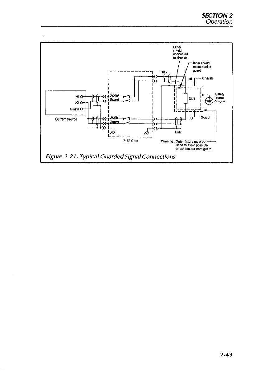
Figure 2-2 I, Typical Guarded Signal Connections
SEC J/ON 2
Operation
2-43
Page 62

SECTION 3
Applications
3.1 INTRODUCTION
This section covers typical applications for the Model 7153 High Voltage
Low Current Matrix card and is organized as follows:
3.2 Semiconductor Test Matrix: Details a semiconductor test matrix
that can be used to perform a variety of different tests on semiconductors
such as FETs.
3.3 Resistivity Testing Using Matrix Switching in a SMU Test System:
Covers methods to measure the resistivity of semiconductor samples using
the van der Pauw method.
WARNING
To provide protection from shock hazards, the test fixture
chassis must be properly connected to a safety earth ground.
A grounding wire (18 AWC or larger) must be attached securely to the test fixture at a terminal designed for safety
rounding (the terminal should be marked with the symbol
-h ). The other end of the grounding wire is then attached to a
b
known safety earth ground, such as a cold water pipe, or a
grounded electrical outlet box.
3.2 SEMICONDUCTOR TEST MATRIX
Two important advantages of a matrix switching system are the ability to
connect avariety of instruments to the device or devices under test, as well
3-1
Page 63

SECTION 3
Aoulications
as the ability to connect any instrument terminal to any device test node.
The following paragraphs discuss a typical semiconductor matrix test system.
3.2.1 System Configuration
Figure 3-1 shows a two Source Measure Unit test configuration. In this example, OUTPUT HI and OUTPUT LO of each Source Measure Unit are
independently switched, allowing for maximum versatility.
‘igurc 3-l. Multi Unit Connections to Mode/ 7153
This test configuration has five DUT test pins.
Source Measure Unit and test fixture connections to the matrix card are
accomplished using Model 7153-TRX cables. These cable assemblies are
3-2
Page 64
SEC JION 3
Adications
terminated with 3.slot triax connectors. On each Source Measure Unit,
notice that the banana jack is used to access OUTPUT LO rather than the
triax connector. This allows OUTPUT LO to be routed to the signal path of
the matrix. On the Source Measure Unit triax connector, OUTPUT LO is
located on the inner shell which, through normal triax connections, would
put OUTPUT LO on the guard path of the matrix card.
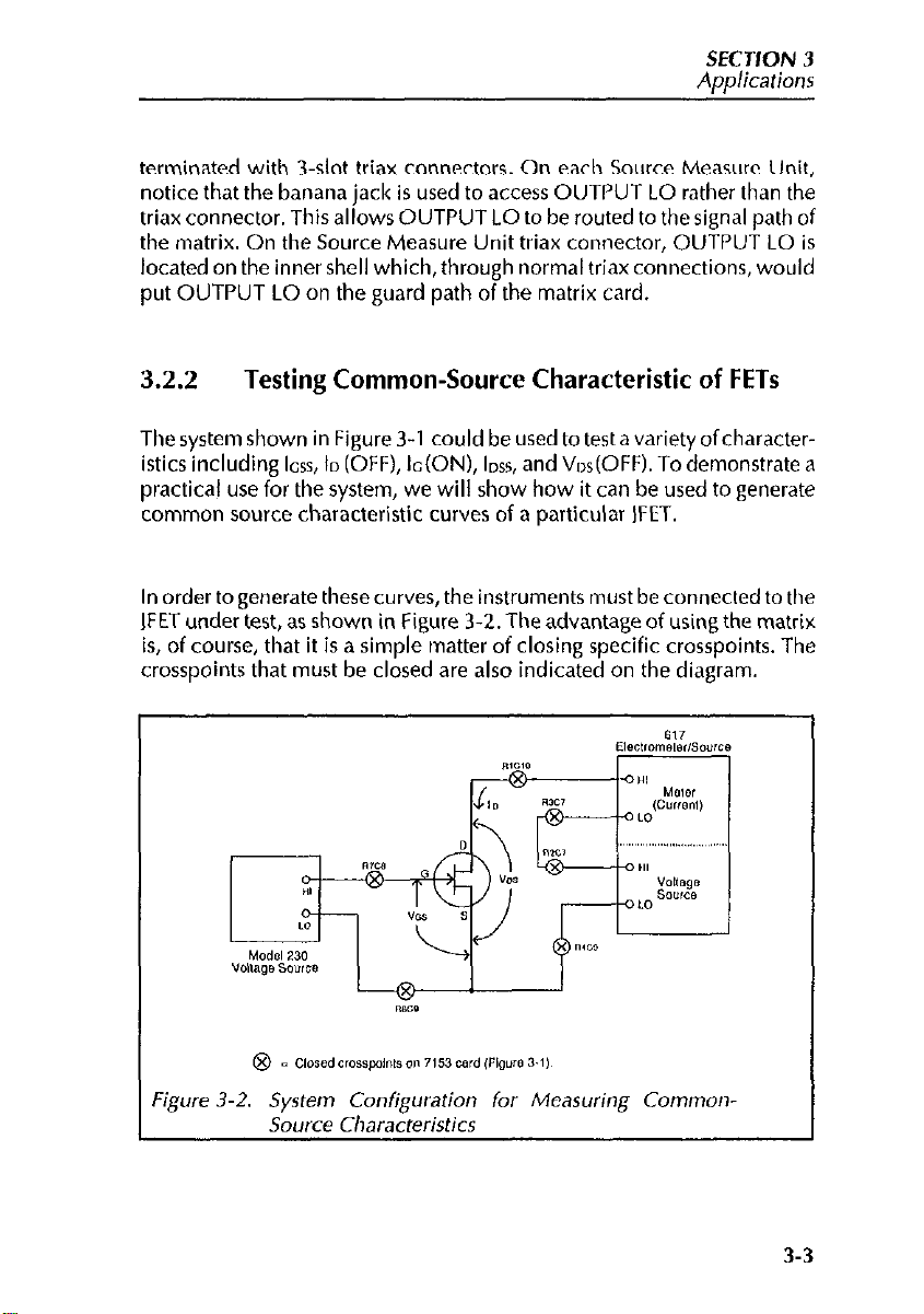
3.2.2
The system shown in Figure 3-1 could be used to test a variety ofcharacter-
istics including ICSS, ID (OFF), Ic(ON), lnss, and Vos(OFF). To demonstrate a
practical use for the system, we will show how it can be used to generate
common source characteristic curves of a particular IFET.
In order to generate these curves, the instruments tnust be connected to the
IFET under test, as shown in Figure 3-2. The advantage of using the matrix
is, of course, that it is a simple tnatter of closing specific crosspoints. The
crosspoints that must be closed are also indicated on the diagram.
Testing Common-Source Characteristic of FETs
‘igure
3-2.
System
Source Characteristics
Configuration
for Measuring Common-
3-3
Page 65

SECT/ON 3
Applications
3.3 RESISTIVITY TESTING USING MATRIX SWITCHING IN A SMU TEST SYSTEM
One example of where matrix switching is beneficial is when performing
resistivity tests on semiconductors. The following paragraphsdiscusssuch
resistivity tests using a Source Measure Unit/matrix switching system.
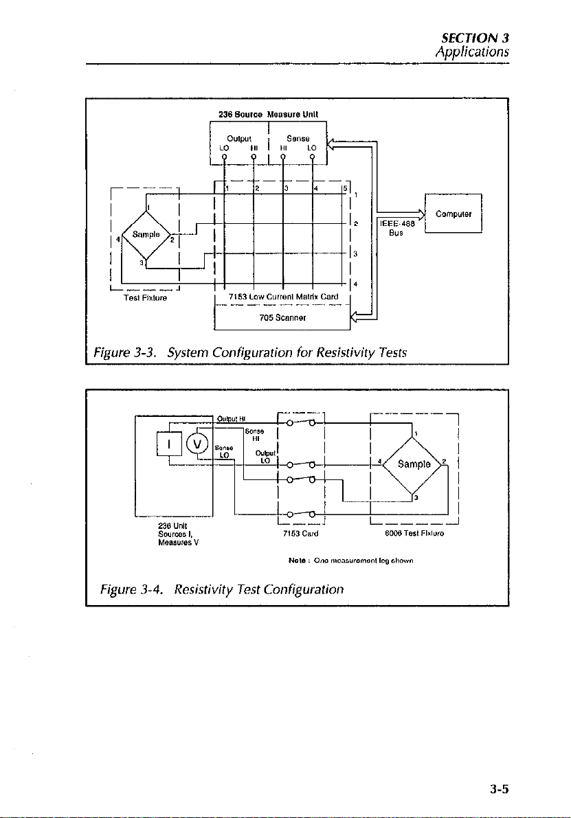
3.3.1 System Configuration
Figure 3-3 shows a typical system configuration for performing resistivity
tests using a Source Measure Unit. In addition to the Source Measure Unit,
which sources the test current and measures the resulting voltage drop
across the DUT, the system includes a Model 705 Scanner and a Model
7153 High Voltage Low Current Matrix Card for switching, as well as a
Model 8006 test fixture to house the device under test.
With the test configuration shown in Figure 3-3, onlyone4.terminal sam-
ple can be tested at any given time. However, additional Model 7153
cards can be daisy chained together to expand columns or rows, allowing
more than one sample to be tested by a single test procedure.
3.3.2 Test Configuration
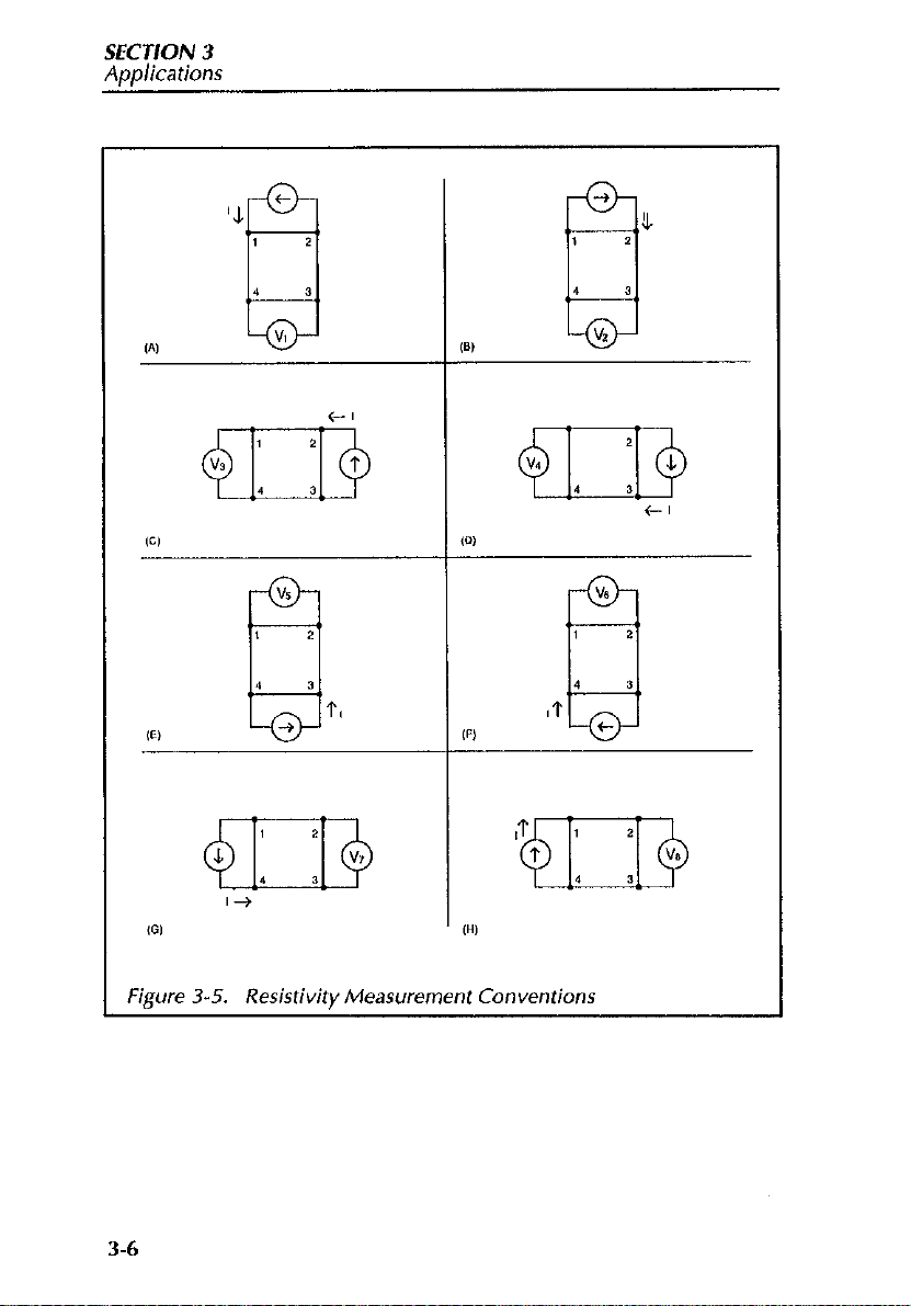
Figure 3-4 shows a typical resistivity test configuration for a single leg
measurement of one sample. Here, the current source of the Source Measure Unit sowces a current between two terminals of the sample, while the
voltage meter section of the unit measures the voltage across two of the
opposite terminals. Generally, eight such measurements are made, as
shown in Figure 3-5.
3.4
Page 66
SECTION 3
Applications
3-5
Page 67
SEC J/ON 3
Applications
Figure 3-5. Resistivity Measurement Conventions
3-6
Page 68
SECTION 3
Aoalications
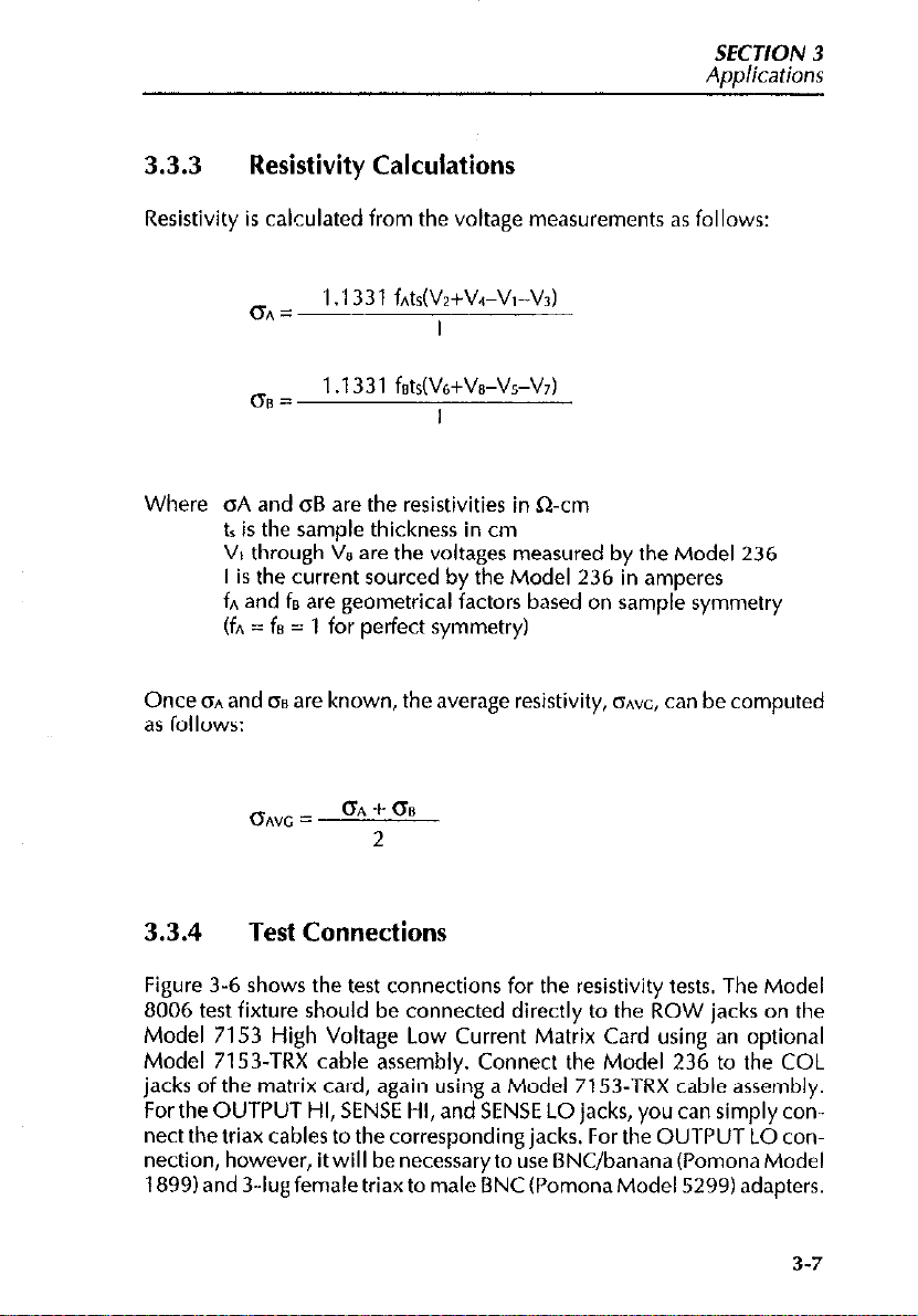
3.3.3 Resistivity Calculations
Resistivity is calculated from the voltage measurements as follows:
~~ = 1 .I 331 fntsw+V4-V,-K)
I
~” = 1 .1331 fsts(V6+Vs-Vs-V,)
I
Where oA and oB are the resistivities in &cm
tr is the sample thickness in cm
V, through Vs are the voltages measured by the Model 236
I is the current sourced by the Model 236 in amperes
fn and fe are geometrical factors based on sample symmetry
(fn = f8 = 1 for perfect symmetry)
Once ISA and 0s are known, the average resistivity, onvc, can be computed
as follows:
OAYC =
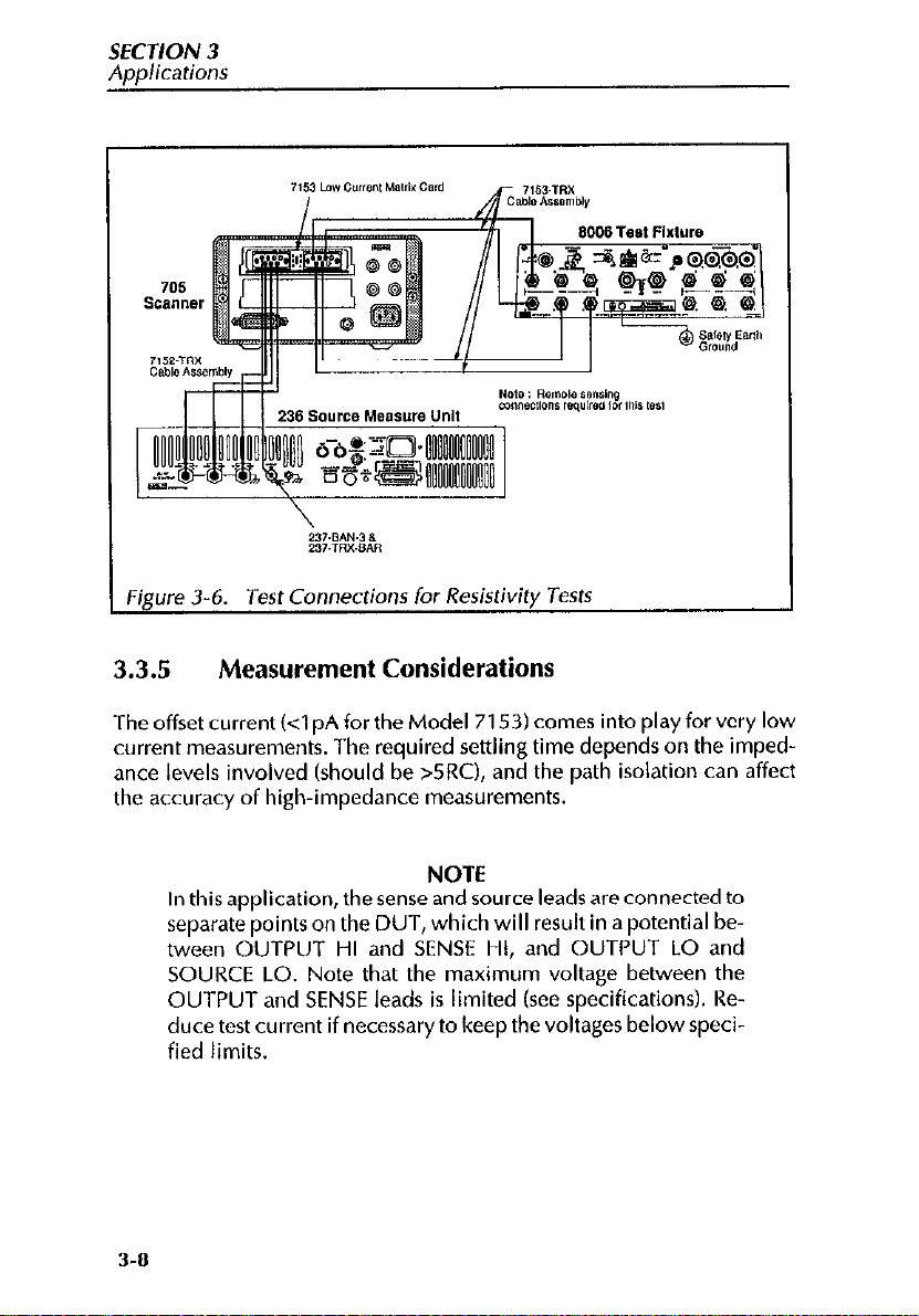
3.3.4
Figure 3-6 shows the test connections for the resistivity tests. The Model
8006 test fixture should be connected directly to the ROW jacks on the
Model 7153 High Voltage Low Current Matrix Card using an optional
Model 7153-TRX cable assembly. Connect the Model 236 to the COL
jacks of the matrix card, again using a Model 7153-TRX cable assembly.
For the OUTPUT HI, SENSE HI, and SENSE LO jacks, you can simply connect the triax cables to the corresponding jacks. For the OUTPUT LO connection, however, it will be necessary to use DNC/banana (Pomona Model
1899) and 3-14 female&w to male BNC (Pomona Model 5299) adapters.
Test Connections
OA + 00
2
3-7
Page 69
SFCJION 3
Applicarions
Figure 3-6.
Jest
Connections
for
Resistivity
Jests
3.3.5 Measurement Considerations
The offset current (4 pA for the Model 7153) comes into play for very low
current measurements. The required settling time depends on the impedance levels involved (should be >5RC), and the path isolation can affect
the accuracy of high-impedance measurements.
NOTE
ln this application, the sense and source leads are connected to
separate points on the DUT, which will result in a potential between OUTPUT HI and SENSE HI, and OUTPUT LO and
SOURCE LO. Note that the maximum voltage between the
OUTPUT and SENSE leads is limited (see specifications). Reduce test current if necessary to keep the voltages belowspecified limits.
3-O
Page 70

SFCJION 3
Applications
3.3.6
Program: Resistivity Tests Using a Switching
Matrix and Source Measure Unit
The following Program demonstrates programming techniques for controlling a switching matrix and Source Measure Unit to perform resistivity
tests. The basic procedure for using this program is as follows:
With power off, connect the Model 23G Source Measure Unit and the
1.
Model 705 Scanner to the IEEE-48t3 bus of the computer. Also, install
the Model 7153 Card in slot 1 of the Model 705 mainframe.
2.
Connect the test fixture and the Source Measure Unit to the matrix
card using the specified triax cables (see Figure 3-6 and the discussion
above for details on test connections).
Turn on the Model 236, and allow it to warm up for at least two hours
3.
for rated accuracy. Be sure that the primary address of the Source
Measure Unit is set to 16. Also, turn on the Model 705, and make sure
that its primary address is set to 17.
4.
Turn on the computer, then boot up BASIC.
Enter lines below into the computer.
5.
Connect the sampleto betested to the appropriate socket terminals on
6.
the test fixture, and also install the necessary test fixture jumpers. Use
the general configuration shown in Figure 3-4 as a guide to test con-
nections. Close the test fixture lid after making connections.
7.
RUN the program, and follow the prompts on the screen. You will be
prompted toenter thedesired sample current value and then the sample thickness, which should beentered in centimeters. When entering
the current, keep the approximate DUT resistance values in mind so
as not to create an over voltage compliance condition. Also, you must
not exceed the maximum voltage between output and sense lends of
the Source Measure Unit.
Oncetheparametersareentered, thetest will begin.TheprogramwiII
8.
program the Source Measure Unit, and then begin the tests by closing
crosspoints. A total of eight measurements will be taken and stored in
an array.
9.
Once the testing has been completed, the resistivityvalues will becalc&ted and displayed.
3-9
Page 71

SECTION 3
Applications
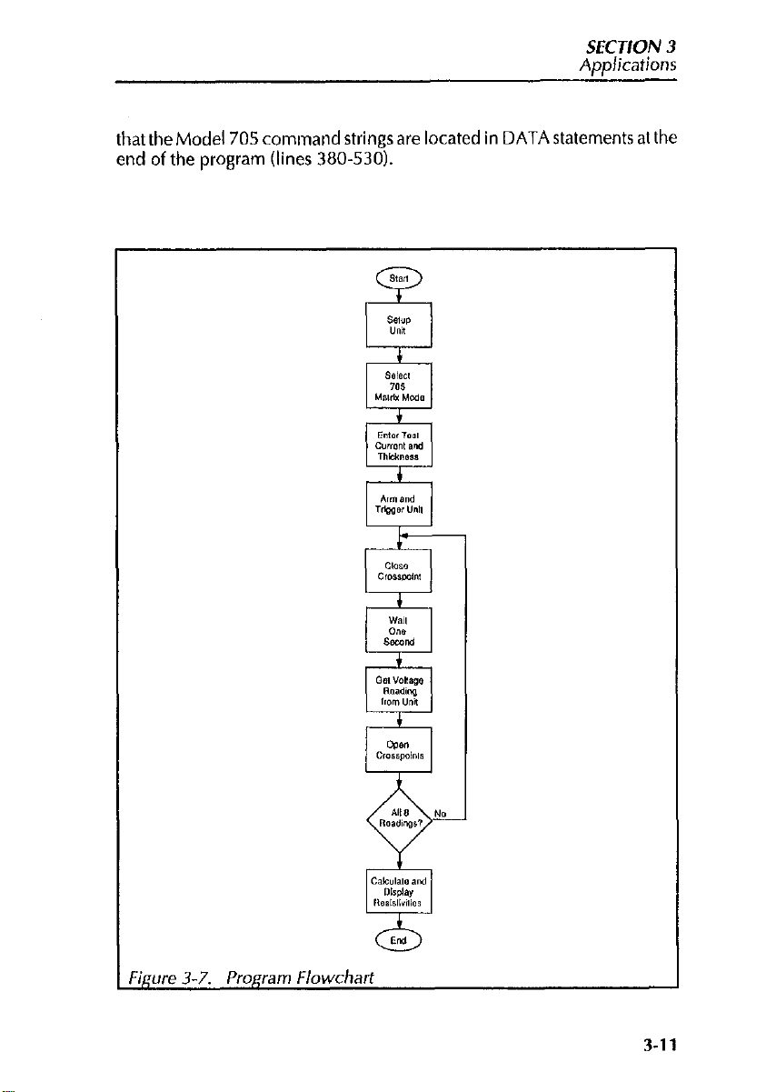
3.3.7
Program Description
Refer to the I’rogram listing below and the flowchart shown in Figure 3-7
for the following description.
At the start of the program, both the Source Measure Unit and the scanner
are returned to default conditions (line 20), and the reading array and command string are dimensioned (line 40). Next, the Model 236, which
sources the test current and measures the sample voltage, is programmed
as follows (lines 60.120):
. Source I, DC mode
l
1 OV compliance, autorange measure
l
Remote sensing
. Measure only data format with no prefix, DC data output
l
Continuous trigger on GET
l
Line cycle integration
The Model 705 is then placed in remote (line 140), and the scanner is
placed into matrix mode (line 150). Next the operator is prompted to input
the desired test current, at which point the Source Measure Unit is programmed with the current value (lines 160 and 170). The operator is then
prompted for the sample thickness (line 180), and the program waits for
the operator’s signal to begin (lines 190 and 200).
Once the operator starts the test, the Model 236 is armed and placed into
operate (line 2101, and the unit is then triggered (line 220). The program
thenentersa loop(line230)to testthesamplewith atotalofeightreadings.
As part of each loop, the Model 705 command string is read from the
DATA statements at the end of the program (line 240), and the unit is then
programmed to close the desired crosspoints (line 250). After a two-second delay for settling (line 2601, a voltage reading is requested from the
Model 236 and placed into an array (line 270). The crosspoints are then
opened by reading the next command string (line 280) and then programming the Model 705 accordingly (line 2901, and then the program loops
back for the tnext Imeasurement (line 300)
Finally, the program computes both IX and 0~ (lines 320 and 330), and
then it calculates and displays the average resistivity, onvc (line 360). Note
3-10
Page 72
SECTION 3
Applications
that the Model 705 command strings are located in DATA statements at the
end of the program (lines 380-530).
Figure
3-7.
Program Flowchart
3-11
Page 73

SECTION 3
Appkations
3-12
Page 74

SECTION 3
Applications
3.4 SMU REMOTE SENSING
The Model 7153 matrix card can also be used by a single Source Measure
Unit for remote sensing. For remote sensing, the Source Measure Unit
could be connected to the matrix card as shown in Figure 3-8. OUTPUT
HI/GUARD, SENSE HI/GUARD, SENSE LO and OUTPUT LO are connected to separate rows for maximum switching flexibility and optimum
lowcurrentperformance. MakingtheSENSE LOconnectionalsoconnects
OUTPUT LO to the matrix card through the triax connector. However,
since it is connected to the inner shield, it is of no consequence as long as it
is not used at the test fixture. In this test configuration, OUTPUT LO is accessed at the Source Measure Unit banana jack so that it can be independently switched.
The test configuration in Figure 3-8 “uses” four matrix rows. Remote sens-
ing can be accomplished using three matrix rows by using OUTPUT LO at
the triax connector. In this configuration, SENSE LO and OUTPUT LO use
the same row. The disadvantage to this is the loss of some switching flexibility. Another option is to make OUTPUT LO a system common that is not
routed (not switched) through the card. All commons are simply
nected directly to the OUTPUT 1.0 banana jack.
con-
For high current applications where leakage current is not a consideration,
the guard paths of the matrix card can be used for 4-wire sensing as shown
in Figure 3-9. With this configuration only two matrix crosspoints are required to accomplish 4.wire connections to the DUT.
3-13
Page 75

SECTION 3
Applications
‘igure 3.0. Remote Sense and Guard Connections fo Model 7753
3-14
Page 76

r
SECTION 3
Applications
Figure 3-9.
Remote Sensing with Guard
3-15
Page 77

SECTION 3
Aodications
REFERENCES
ASTM, F76-84. “Standard Method for Measuring Hall Mobility and Hall
Coefficient in Extrinsic Semiconductor Single Crystals”. Annual Bk. ASTM
Stds., 1986: 10.05 155.
Coyle, G. et al, Switchinc! Handbook. Keithley Instruments Inc., Cleveland, Ohio (1987).
Van der Pauw, L. J. “A Method of Measuring Specific Resistivity and Hall
Effects of Discs of Arbitrary Shape”. Philips Rec. Repts., 1958: 13 1.
3-16
Page 78

SECTION 4
Service Information
4.1 INTRODUCTION
This section contains information necessary to service the Model 7153
High Voltage Low Current Matrix Card and is arranged as follows:
4.2 HandlingandCleaning Precautions: Discusses handling precautions
and methods to clean the card should it become contaminated.
4.3 Performance Verification: Covers the procedures necessary to determine if the card is operating properly.
4.2 HANDLING AND CLEANING PRECAUTIONS
Because of the high-impedance circuits on the Model 7153, care should
be taken when handling or servicing the card to prevent possible contami-
nation. The following precautions should be taken when servicing the
card.
1. Handlethecardonly bytheedges. Do not touch any board surfaces or
components not associated with the repair.
2. DO not store or operate the card in an environment where dust could
settle on the circuit board. Use dry nitrogen gas to clean dust off the
board if necessary.
3. Should it become necessary to use solder on the circuit board, remove
the flux from the work areas when the repair has been completed. Use
Freon@ TMS or TE or the equivalent along with clean cotton swabs or
a clean, soft brush to remove the flux. Take care not to spread the flux
4-1
Page 79

SECTION 4
Service Information
to other areas of the circuit board. Once the flux has been removed,
swab only the repaired area with methanol, then blow dry the board
with dry nitrogen gas.
4. After cleaning, the card should be placed in a 50°C low-humidity environment for several hours before use.
4.3 PERFORMANCE VERIFICATION
WARNING
The following test procedures should only be performed by
qualified personnel who recognize shock hazards and are familiar with the safety precautions required to avoid possible
injury.
The following paragraphs discuss performance verification procedures for
the Model 7153, including offset (leakage) current, contact potential, path
isolation, input isolation (differential and common mode), and path resistance.
All test procedures are to be performed with the Model 7153 installed in a
Model 705 or 706 scanner mainframe. Also, the matrix card being
checked must NOT be connected to any other card.
4.3.1 Environmental Conditions
All verification measurements except for isolation and offset current
should be made at an ambient temperature between O’C and 35°C and at a
relative humidity of less than 70%. Path isolation, input isolation and offset
current verification must be performed at an ambient temperature of 23’C
and at a relative humidity of less than 60%. lfthe matrix card has been subjected to temperature or humidity extremes, allow the card to environmentally stabilize for at least one hour before performing any tests.
4.3.2
Table 4-1 summarizes the equipment necessary to make the performance
verification tests, along with the application for each item.
4-2
Recommended Test Equipment
Page 80

Service Information
Table 4-1. Recommended Test Equipment
SECT/ON 4
Manufacturer
Keithley
Keithley 181 Nanovoltmeter
Keithley
Keithley
Keithley 7153-TRX
Keithley
Keithley 6012
Keithley 6172
AMP 201144-l
Model or
Part No. Description
617 Electrometer
196 DMM
705 or 706 Scanner mainframe
Matrix to Triax Cable Offset current and
6011 Triax to alligator clip Common mode in-
cable
Triax to UHF adapter Differential input
2-slot to 3-lug triax
adapter
Guard terminal extender
Applications
Offset current and
isolation
Contact potential
Path resistance
All tests
path isolation
put isolation
isolation
Offset current, path
isolation and com-
mon mode input
isolation
Common mode input isolation and
contact potential
Signal terminal extender (#26 AWC
copper wire)
Keithley
Keithley 237-BAN-3 ;;;x to Banana Ca-
1481 Low thermal input
cable
Contact potential
Contact potential
Path Isolation
4-3
Page 81

SECTION 4
Service Information
Recommended Test Equipment (Cont.)
Coax crimping tool
Female to Female
See Table 4-2
4.3.3 Special Connection Requirements
Many of the procedures in this section require special cables and connec-
tors. The following provides the information needed to construct this
equipment. The parts used to prepare this equipment are listed in
Table 4.2.
Signal to Guard Shorting Plug
One low thermal shorting plug is required to check path resistance and
contact potential. The shorting plug (see figure 4-l 1 is built by modifying a
miniature coaxial connector pin. The short is accomplished by jamming a
small length of #24 AWG copper wire between the center conductor (sig-
nal) and the outer casing (guard). The wire is then soldered to the connec-
tor pin.
4-4
Page 82

Table 4-2. Special Connection Parts
Description
Signal to Guard Short
Miniature coax connector
Coax to Banana Cable
Miniature coax connector
Coax Cable
Banana plugs (2 required)
Ferrule
Signal Terminal Extender
Miniature coax connector
Coax Cable
Ferrule
Model or
Part No.*
Amp 201 144-1
Amp 201144-l
Eelden@
DC-1 o-2
cs-747-3
Amp 201144-l
Belden@9239
cs-747-3
Service Information
SECTION 4
Application
Contact potential and path
resistance
Differential
input isolation
Contact potential
Figure 4-l. Signal-to-Guard Short Preparation
4-5
Page 83

SFCJION 4
Service Information
Coax to Banana Cable
One coax/banana cable is required to check path resistance and differential input isolation. The coax/banana cable is shown in Figure4-2. A mini-
ature coaxial female connector pin is connected to a suitable length of coaxial cable using the AMP-45638-2 crimping tool. Banana plugs are then
connected to the other end of the cable as shown in the drawing. The cable
should be kept as short as possible.
WARNING
High voltage will be present on the guard terminal when
checking input isolation. To avoid electrical shock that could
result in injury or death, make sure that the twisted braid
(guard) of the cable is adequately insulated.
Signal Terminal Extender
In order to check contact potential, a signal terminal extender is required.
Figure 4-3 shows how a signal extender can be built. A suitable length of
coaxial cable is connected to a female coaxial connector pin. A portion of
the outer shield and inner insulator of the cable is then removed to expose
a section of the center conductor (signal terminal). Make sure the outer
shield (guard) does not short out to the center conductor (signal).
4-6
Page 84
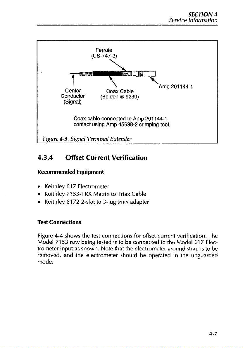
Service Information
SECTION 4
Center
Conductor
(Signal)
Coax cable connected to Amp 201144-l
I
Figure 4-3. Signal Terminal Extender
4.3.4
contact using Amp 45639-2 crimping tool.
Offset Current Verification
Coax Cable
(Selden @ 9239)
Amp 201144-l
Recommended Equipment
l
Keithley 617 Electrometer
l
Keithley 7153-TRX Matrix to Triax Cable
l
Keithley 6172 2&t to 3.1~16 triax adapter
Test
Connections
Figure 4-4 shows the test connections for offset current verification. The
Model 7153 row being tested is to be connected to the Model 617 Electrometer input as shown. Note that the electrometer ground strap is to be
removed, and the electrometer should be operated in the unguarded
mode.
4.7
Page 85
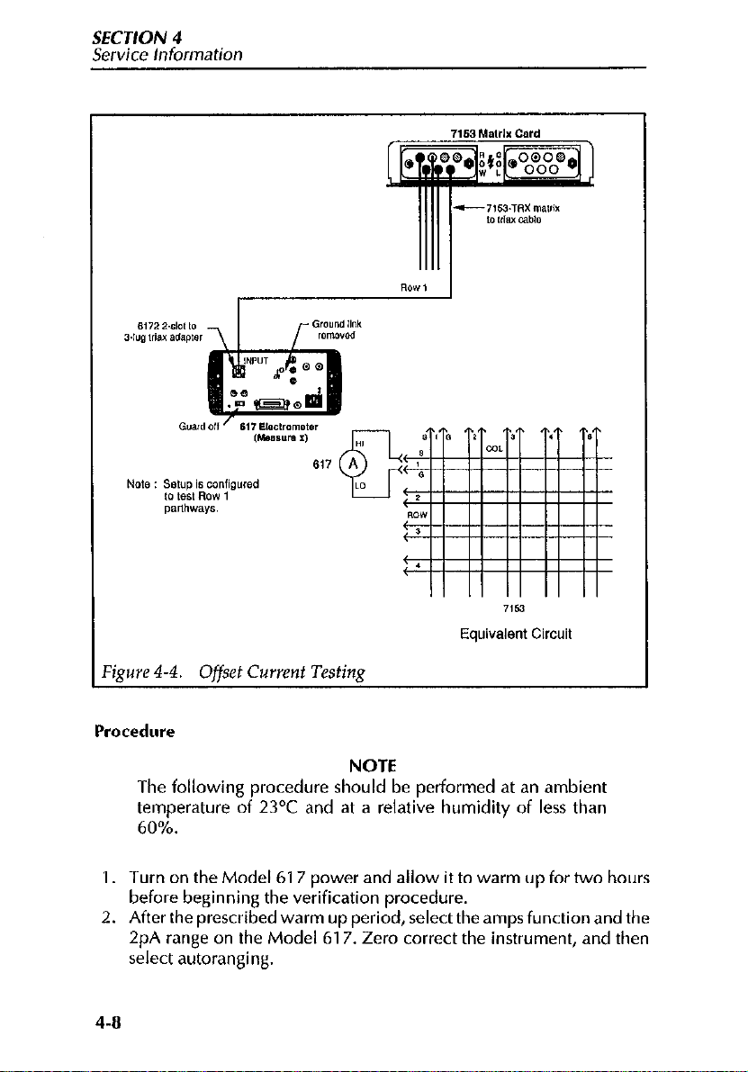
SECTION 4
Service Information
Figure 4-4. Offset Current Testinn
Procedure
NOTE
The following procedure should be performed at an ambient
temperature of 23OC and at a relative humidity of less than
60%.
1. Turn on the Model 617 power and allow it to warm up for two hours
before beginning the verification procedure.
2. After the prescribed warm up period, select the amps function and the
2pA range on the Model 617. Zero correct the instrument, and then
select autoranging.
4-8
Page 86

Service
3. Connect the Model 617 to row 1 of the Model 7153, as shown in
Figure 4-4.
4. Close crosspoint RlCl (row 1, column 1) by using the Model 705 or
706 front panel controls.
5. Disable zero check on the Model 617, and allow the reading to settle.
6. Verify that the offset current reading is <l pA.
7. Enable zero check on the Model 617, and open crosspoint Rl Cl,
0. Repeat steps 4 through 7 for crosspoints Rl C2 through Rl C5. Only
one crosspoint at a time should be closed.
9. Disconnect the cable from row 1, and connect it instead to row 2.
10. Repeat steps 4 through 7 for crosspoints R2Cl through R2C5. Only
one crosspoint at a time should be closed.
11. On the Model 617, enable zero check.
12. Repeat steps 3 through 8 for rows 3 and4. Theelectrometershould be
connected to the row being tested, and only one crosspoint must be
closed at a time.
Information
4.3.5 Contact Potential Verification
Recommended Equipment
SECTION 4
l
Keithley 181 Nanovoltmeter
l
Keithley Model 1481 Low Thermal Input Cable
l
Signal to guard short (custom built; see Figure 4-l)
. Signal Terminal Extender (custom built; see Figure 4-3)
. Guard Terminal Extender (AMP-201 144-l)
Test Connections
Figure 4-5 shows the test connections for contact potential verification.
4-9
Page 87

SECTION 4
Service
Information
Procedure
1. Turn on Model 181 power and allow to warm up for one hour.
2. Connect the Model 1481 cable to the Model 181.
3. Connect the jumper to column 1 at theCOL receptacle and install the
Signal Terminal Extender in row 1 of the ROW receptacle.
After the prescribed warm up period, set the Model 181 to the 2mV
4.
range, short the alligator clips ofthe cable together, and press ZERO to
null out internal offset. LeaveZERO enabled for theentire procedure.
5. Referring to Figure 4-5, connect the Model 181 to row 1 signal and
column 1 jumper of the matrix card.
6. Program the mainframe to close crosspoint Rl Cl (row 1, column 1).
4-10
Page 88

Service Information
SECTION 4
Verify that the reading on the Model 181 is <2OpV.
7.
8.
From the mainframe, open crosspoint RlCl and move the jumper to
column 2.
9.
Repeat steps 6 through 8 to check the rest of the signal pathways
(crosspoints RI C2 through Rl C5)ofthe row. Only one crosspoint at a
time should be closed.
10.
Remove the Signal Terminal Extender from row 1 and install the
Guard Terminal Extender.
11.
Repeat step 6 through 9 to check the guard pathways of row 1.
12.
Repeat steps 5 through 11 for rows 2 through 4. The nanovoltmeter
should beconnectedto the row beingtestedand the jumpershould be
connected to the column being tested.
4.3.6
Path isolation Verification
These tests check the leakage resistance (isolation) between adjacent matrix paths. Should the card fail any of the tests, clean it using the procedures
outlined in paragraph 4.2.
Recommended Equipment
l
Keithley 617 Electrometer
. Keithley 7153.TRX Matrix to Triax Cable
l
Keithley 6172 2-slot to 3-lug triax adapter
l
Pomona 5278 female to female triax adapter
. Triax to banana cable (custom built; see paragraph 2.6.3)
Test Connections
Figure 4-6 shows the test connections for the path isolation tests. One row
being tested is to be connected to the Model 617 Electrometer input
through a Model 61 72 2.slot female to 3&g male triaxial adapter. The
other row is to be connected to the voltage source HI terminal using a specially prepared triadbanana cable, the construction ofwhich is explained
in paragraph 2.6.3. Note that both the inner shield and the center conductor are to be connected to the banana plug.
4-11
Page 89
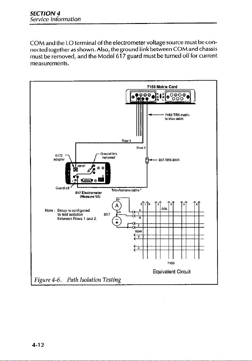
SECTION4
Service Information
COM and the LO terminal of the electrometer voltage source must be connected togetherasshown.Also,theground IinkbehveenCOMandchassis
must be removed, and the Model 617 guard must be turned off for current
measurements,
Figure 4-6. Path Isolation
4-12
,153
Equivalent Circuit
Testing
Page 90

Service Information
SECTION 4
WARNING
Hazardous voltage from the electrometer voltage source will
be used in the following steps. Take care not to contact live
circuits, which could cause personal injury or death.
NOTE
The following procedure must be performed at an ambient
temperature of 23’C and at a relative humidity of less than
60%.
1. Turn on theModel 617 and allow it to warm up for two hours for rated
accuracy.
2. After the prescribed warm up period, select the Model 617 amps function, and enable zero check. Select the 20pA range, and zero correct
the instrument.
3. Connect theModel 617 to rows 1 and 2 of the matrix card, as shown in
Figure 4-6.
4. Program the Model 617 voltage source for a value of i-1 OOV, but do
not turn on the voltage source output.
5. Close crosspoints RlCl (row 1, column 1) and R2C2 (row 2, column
2) from the mainframe.
6. With the Model 617 in amps, enable suppress after the reading has
settled.
7. Turn on the Model 617 voltage
ohms function on the electrometer.
8. After the reading has settled, verify that the resistance is >lOl-!J
(I O’Q,.
9. Turn off the voltage source, and enable zero check. Disable suppress,
and select the amps function on the electrometer.
10. From the front panel ofthe mainframe, press the RESET button to open
all crosspoints.
11. Using Table 4-3 as a guide, repeat steps 5 through 10 for the
crosspoint pairs listed starting with Test No. 2. Note that Model 617 is
connected to rows 2 and 3 for tests 5 through 8, and connected to
rows 3 and 4 for tests 9 through 12. Before moving the test connec-
tions, make sure the voltage source is off.
source
output, and enable the V/l
4-13
Page 91
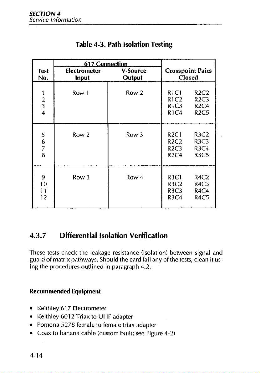
SECTION 4
service Information
Table 4-3. Path isolation Testing
Test
NO.
Electrometer V-Source
Input output
617 -ion
Crosspoint Pairs
Closed
1 Row 1 Row 2
2
3
4
5
Row 2 Row 3
6
7
8
9
10
11
Row 3 Row 4
12
4.3.7
These tests check the leakage resistance (isolation) between signal and
guard of matrix pathways. Should the card fail any of the tests, clean it using the procedures outlined in paragraph 4.2.
Differential Isolation Verification
RlCl R2C2
RlC2 R2C3
RlC3 R2C4
RlC4 R2C5
R2Cl
R2C2 R3C3
R2C3
R2C4 R3C5
R3Cl R4C2
R3C2 R4C3
R3C3 R4C4
R3C4 R4C5
R3C2
R3C4
Recommended Equipment
. Keithley 617 Electrometer
Keithley 6012 Triax to UHF adapter
.
Pomona 5278 female to female triax adapter
l
Coax to banana cable (custom built; see Figure 4-2)
l
4-14
Page 92

Service Information
SECTION 4
Test Connections
Figure 4-7 shows thetest connections for the path isolation tests. The cable
is connected to the row beingtested. One banana plug (signal) of the cable
is to be connected to the Model 617 Electrometer input through a Model
6012 triax to UHF adapter. The plug mates to the center conductor of the
UHF connector. The other banana plug (guard) connects to the electrome-
ter voltage source.
Figure 4-7.
Differential Input Isolation Testing
7153
Equivalent
Circuit
4-15
Page 93

SECTION 4
Service information
COM and the LO terminal ofthe electrometer voltage source must be con-
nected togetherasshown. Also, theground link between COM andchassis
must be removed, and the Model 617 guard must be turned off for current
measurements.
Procedure
WARNING WARNING
Hazardous voltage from the electrometer voltage source will Hazardous voltage from the electrometer voltage source will
be used in the following steps. Take care not to contact live be used in the following steps. Take care not to contact live
circuits, which could cause personal injury or death. circuits, which could cause personal injury or death.
NOTE
The following procedure must be performed at an ambient
temperature of 23’C and at a relative humidity of less than
60%.
1. Turn on theModel 617 and allow ittowarm upfortwo hours for rated
XCllLXy.
2. After theprescribedwarm up period, selecttheModel617 ampsfunction, and enable zero check. Select the 2nA range, and zero correct
the instrument.
3. Connect the Model 617 to row 1 of the matrix card, as shown in
Figure 4-7.
4. Program the Model 617 voltage source for a value of +l OOV, but do
not turn on the voltage source output.
5. Close crosspoint Rl Cl (row 1, column 1) from the mainframe.
6. With the Model 617 in amps, enable suppress after the reading has
settled.
7. Turn on the Model 617 voltage source output, and enable the V/l
ohms function on the electrometer.
l3. After the reading has settled, verify that the resistance is >l OTa
(low).
9. Turn off the voltage source, and enable zero check. Disable suppress,
and select the amps function on the electrometer.
10. From the front panel ofthe mainframe, press the RESET button to open
the crosspoint.
11. Connect the Model 617 to row 2 of the matrix card and repeat steps 5
through 10 for crosspoint,R2C2.
4-16
Page 94
Service information
SECTION 4
12. Connect the Model 617 to row 3 of the matrix card and repeat steps 5
through
10 for crosspoint R3C3.
13. Connect the Model 617 to row 4 of the matrix card and repeat steps 5
through 10 for crosspoint R4C4.
14. With the electrometer still connected to row 4, repeat steps 5 through
10 for crosspoint R4C5.
4.3.8 Common Mode Isolation Verification
These tests check the leakage resistance (isolation) between signal/guard
and chassis ground of matrix pathways. Should the card fail any of the
tests, clean it using the procedures outlined in paragraph 4.2.
Recommended Equipment
l
Keithley 617 Electrometer
. Keithley 6011 Triax to alligator clip cable
l
Signal to guard short (custom built; see Figure 4.1)
Test Connections
Figure 4-8 shows the test connections for these tests. The Model 6011 cable is connected to the electrometer input as shown. The alligator clip on
the black test lead of the cable is connected to the screw housing of the
receptacle (chassis ground). The signal to guard short is installed in the row
to be tested. The alligator clip on the red test lead is then connected to the
short (signal/guard).
The Model 617 guard must be turned off for current measurements.
4-17
Page 95

SECTION 4
Service
Information
Equivalent Circuit
%mre 4-8.
Procedure
The following procedure must be performed at an ambient
temperature of 23°C and at a relative humidity of less than
60%.
Turn on the Model 617 and allow it to warm up for two hours for rated
I.
accuracy.
4-18
Common ModeInput
Isolation Testina
NOTE
Page 96
Service Information
2. Afterthe prescribedwarm up period, selectthe Model 617 ohmsfunction, enable zero check, and select the 1 OGn range.
3. Connect the Model 617 to row 1 and chassis ground of the matrix
card, as shown in Figure 4-8.
4. Close crosspoint Rl Cl (row 1, column I) from the mainframe.
5. On the Model 617, release zero check. After the reading has settled,
verify that the resistance is >I GI;1 (lOYQ2).
6. On the Model 617, enable zero check.
7. From the front panel ofthe mainframe, press the RESET button to open
the crosspolnt.
8. Connect the short and red test lead from the Model 617 to row 2 of the
matrix card and repeat steps 4 through 7 for crosspoint RZC2.
9. Connect the short and red test lead from the Model 617 to row 3 and
repeat steps 4 through 7 for crosspoint R3C3.
10. Connect the short and red test lead from the electrometer to row 4 and
repeat steps 4 through 7 for crosspoint R4C4.
11. With theelectrometer still connected to row4, repeat steps4 through
7 for crosspoint R4C5.
4.3.9 Path Resistance Verification
SECTION 4
The following paragraphsdiscuss theequipment, connections, and procedure to check path resistance. Should a particular pathway fail the resistance test, the relay (or relays) for that particular crosspoint is probably defective. See the schematic diagram at the end of Section 5 to determine
which relay is defective.
Recommended Equipment
l
Keithley 196 DMM
l
Banana to clip-on test lead
l
Coax to banana cable (custom built; see Figure 4-2)
l
Signal to guard short (custom built; see Figure 4-l)
4-19
Page 97

SECTION 4
Service Information
Connections
Figure 4-9 shows the connections for the path resistance tests. A specially
prepared shorting plug is used to connect signal to guard, and is installed at
the column being tested. The Model 196 low terminal is connected to the
shorted column usingthe banana/clip-on test lead. This test lead clipsonto
the installed shorting plug. The high terminal of the DMM connects to the
row being tested using the specially constructed coax/banana cable.
Procedure
Turn on the Model 196 DMM and allow it to warm up for at least one
1.
hour before beginning the test.
Using Figure 4-9 as a guide, connect the cable (signal) and test lead to
2.
the DMM, but do not make connections to the matrix card.
Temporarily clip the test lead to the inner conductor of the coax con-
3.
nector pin of the cable. This will short the DMM input.
Select the ohms function, 3OOn range, and 5-l/2 digit resolution on
4.
the Model 196.
After the reading settles, enable zero on the Model 196 DMM. Leave
5.
zero enabled for the following tests.
6. Connect the cable and test lead to the matrix card as shown in
Figure 4-9.
7. From the mainframe, close crosspoint RlCl (row 1, column 1) and
allow the reading to settle. Verify that the resistance reading is < 2n.
On the mainframe, press the RESET button to open the crosspoint.
8.
Repeat steps 7 and 8 for columns 2,3 and 4. In each case the short and
9.
test lead must be connected to the column under test, and the
crosspoint must be closed.
IO. Repeat steps 7 through 9 for rows 2, 3 and 4. In each case, the elec-
trometer is connected to the row under test. The crosspoint to close is
the one corresponding to the row and column connections at that
time. In all cases, the measured resistance should be < 2Q.
11. Disconnect the coax/banana cable from the matrix card and the
DMM. Also, disconnect the clip-on test lead from the matrix card.
12. On the Model 196, disable zero.
13. Connect the guard banana plug of the cable to the HI terminal of the
DMM. Do not make any connections to the matrix card.
Temporarily clip the test lead on to the outer shell of the coax connec-
14.
tor pin of the cable. This will short the DMM input.
15. After the reading settles, enable zero on the Mddel 196. Leave zero
enabled for the remaining tests.
4-20
Page 98
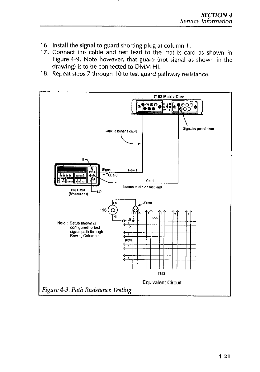
Service Information
SECTION 4
16. Install the signal to guard shorting plug at column
17. Connect the cable and test lead to the matrix card as shown in
Figure 4-9. Note however, that guard (not signal as shown in the
drawing) is to be connected to DMM HI.
18. Repeat steps 7 through 10 to test guard pathway resistance.
1.
‘&we 4-9. Path Resistance Tcstinx
Equivalent
Circuit
4-21
Page 99
SECTION 5
Replaceable Parts
5.1 INTRODUCTION
This section contains a list of replaceable electrical and mechanical parts
for the Model 7153, as well as a component layout drawing and schematic
diagram of the card.
5.2 PARTS LIST
Electrical parts are listed in order of the circuit designation. A miscellaneous parts list table is located at the end of this section.
5.3 ORDERING INFORMATION
To place a parts order, or to obtain information concerning replacement
parts, contact your Keithley representative or the factory (see the inside
front cover for addresses). When ordering parts, be sure to include the fol-
lowing information:
1. Card model number
2. Card serial number
3. Part description
4. Circuit description, if applicable
5. Keithley part number
5.4 FACTORY SERVICE
If the card is to be returned to Keithley Instruments for repair, perform the
following:
5-l
Page 100

SECTION 5
Replaceable Parts
1, Complete the service form at the back of this manual and include it
with the card.
2. Carefully pack the card in the original packing carton.
3. Write ATTENTION REPAIR DEPARTMENT on the shipping label.
5.5 COMPONENT LAYOUT AND SCHEMATIC DIAGRAM
A component layout of the driver board is contained in drawing number
7153-160, while drawing number 7153-166 contains a schematic diagram. A component layout of the delay board is contained in drawing
number7153-100,whiledrawingnumber7153-106containsaschematic
diagram.
5-2
 Loading...