

Page 1

Model 7 116~MWS
Microwave Switch System
Instruction
Manual
Contains Operating and Servicing Information
Page 2

WARRANTY
Keithley Instruments, Inc. warrants this product lo he free from deCects in material and workmanship for a period of I year from date of
shipment.
Keithley Instruments, Inc. warrants the following items for 90 days from the date of shipment: probes, cables, rechargeable batteries,
diskettes, and documentation.
During the Wmnty period, we will, at our option, cithcr repair or rcplacc any product that proves to be defective.
To exercise this warranty, write or call your local Keithley representative, or contact Kcithlcy headquwtcrs in Cleveland, Ohio. You will
be given prompt assistance and return instructions. Send the product, transportation prepaid, to the indicated service facility. Repairs
will be made and the product returned, transportation prepaid. Repaired or replaced products arc warranted Coor the balance of the original warranty period, or at least 90 days.
LIMITATION OF WARRANTY
This warranty does not apply to defects resulting from product modilication without Keithley’s express written consent, or misuse of
any product or part. This warranty also does not apply to fuses, software, non-rechargeable batteries, damage from battery leakage, or
problems arising from normal wew or failure to follow instructions.
THIS WARRANTY IS IN LIEU OF ALL OTHER WARRANTIES, EXPRESSED OR IMPLIED, INCLUDING ANY IMPLIED
WARRANTY OF MERCHANTABILITY OR FITNESS FOR A PARTICULAR USE. THE REMEDIES PROVIDED HEREIN ARE
BUYER’S SOLE AND EXCLUSIVE REMEDIES.
NEITHER KEITHLEY INSTRUMENTS, INC. NOR ANY OF ITS EMPLOYEES SHALL BE LIABLE FOR ANY DIRECT, INDIRECT, SPECIAL, INCIDENTAL OR CONSEQUeNTIAL DAMAGES ARISING OUT OF THE USE OF ITS INSTRUMENTS AND
SOFTWARE EVEN IF KEITHLEY INSTRUMENTS, INC., HAS BEEN ADVISED IN ADVANCE OF THE POSSIBILITY OF
SUCH DAMAGES. SUCH EXCLUDED DAMAGES SHALL INCLUDE, BUT ARE NOT LIMITED TO: COSTS OF REMOVAL
AND INSTALLATION, LOSSES SUSTAINED AS THE RESULT OF INJURY TO ANY PERSON, OR DAMAGE TO PROPERTY,
Keithley Instruments, Inc. * 28775 Aurora Road - Cleveland, OH 44139 * 440-248-0400 *Fax: 440-248-6168 * http://www.keithley.com
Page 3
Model 7116-MWS 16-Channel Microwave Switch System
Instruction Manual
01996, Keithley Instruments, Inc.
All rights reserved.
Cleveland, Ohio, U.S.A.
Third Printing, July 1998
Document Number: 7116MWS-901-01 Rev. C
Page 4

Manual Print History
The print history shown below lists the printing dates of all Revisions and Addenda created toor this manual. The Revision
Level letter increases alphabetically as the manual undergoes subsequent updates. Addenda, which are released between Revisions, contain important change inkmnation that the user should incorporate immcdiatcly into the manual. Addenda are numbered sequentially. When a new Revision is crcatcd, all Addenda associated with the previous Revision of the manual we
incorporated into the new Revision of the manual. Each new Revision includes a revised copy oi this print history page.
Page 5

Safety Precautions
The following safety precautions should bc observed before using
this product and any associated instrumentation. Although some instruments and acccssorics would normally be used with non-hazardous voltages, there are situations where hazardous conditions
may bc prcscnt.
This product is intended for USC by qualified personnel who recognize shock hazards and arc familiar with the safety precautions required to avoid possible injury. Read tbc operating infoarmation
carefully beforc using the product.
The types of product users are:
Responsible body is the individual OT group responsible for the use
and maintenance of equipment. and for ensuring that operators are
adequately uained.
Operators use the product for its intended function. They must be
trained in electrical safety procedures and proper use of the instrument. They must he prolected from electric shock and contact with
hazardous live circuits.
Maintenance personnel perform routine procedures on the product
to keep it operating, for example, setting the line voltage or replacing consumable materials. Maintenance procedures are described in
the manual. The procedures explicitly state if the operator may perform them. Otherwise, they should he performed only by service
perS”““el.
Service
personnel
safe instatIations and repairs of products. Only properly trained service personnel may perform installation and service procedures.
Exercise extreme caution when a shock hazard is present. Lethal
voltage may he present on cable connector jacks or test fixtures. The
American National Standards Institute (ANSI) states that a shock
hazard exists when voltage levels greater than 30V RMS, 42.4V
peak,
or 60VDC are present. A good safety practice is to expect
are trained to work on live circuits, and perform
that hazardous voltage is present in any unknown circuit before
measuring.
Users of this product most he protected from electric shock at all
Limes. The responsihlc body nest ensue thal users are prevented
access and/or insulated from every connectloo point. In some cases,
connections must bc exposed to potential human contact. Product
UXTS in these circumstances most be trained to prolect themselves
from the risk of electric shock. If the circuit is capable of operating
at or above 1000 volts, no conductive part of the circuit may he
exposed.
As described in the International Electrotechnical Commission
(IEC!) Standard IEC 664, digital multimeter measuring circuits
(e.g., Keitbley Models 175A. 199,2000,2OUl, 2002, and 2010) arc
Installation Category II. All other instruments’ signal terminals are
Installation Category I and must not be connected to mains.
Do not connect switching cards directly to unlimited power circuits.
They are intended to he used with impedance limited sources.
NEVER connect switching cards directly to AC mains. When connecting sources to switching cards, install protective devices to limit fault torrent and voltage to the card.
Before operating an instrument, make sore the line cord is connect-
ed to a properly grounded power receptacle. Inspect the connecting
cables, test leads, and jumpers for possible wear, cracks, or breaks
before each use.
For maximum safety, do not touch the product, test cables, 01 any
other instroments while power is applied to the circuit under test.
ALWAYS remove power from the entire test system and discharge
any capacitors before: connecting or disconnecting cables or jumpers, installing or removing switching cards, or making internal
changes, such as installing or removing jumpers.
Do not touch any object that could provide a torrent path to the
common side of the circuit under lest or power line (earth) ground.
Always make measurements with dry hands while standing on a
dry, insulated surface capable of withstanding the voltage being
measured.
Page 6
Do not exceed the maximum signal levels of the instruments and accessories, as dcfincd in the specilications and upcrating information, and as shown on tbc instrument or test fixture panels, or
switching card.
When fuses are used in a product, replace with same type and rating
for continued protection against fire hazard.
Chassis connections must only be used as shield connections for
measuring circuits, NOT as safety earth ground connections.
If you arc using a test fixture, keep the lid closed while power is applied to the device under test. Safe operation requires tbc USC of a
lid interlock.
Ifa@ screw is prcscnt, connect it to safety earth ground using the
wire recommended in the user documentation.
The A symbol on an instrument indicates that the user should rcfer to the operating instructions located in the manual.
Then
sure 1000 volts or more, including tbc combined effect of normal
and common mode voltages. USC standard safety precautions to
avoid personal contact with these voltages.
The WARNING heading in a manual explains dangers that might
result in personal injury or death. Always read the associated information very carefully before performing the indicated procedure.
symbol on an instrument shows that it can sowcc or mea-
lnslrumcntation and accessories shall not be connected to humans.
Before performing any maintenance, disconnect the line cord and
all test cables.
‘To maintain protection from electric shock and fix, rcplacemcnt
components in mains circuits, including the power transformer, test
leads, and input jacks, must be purchased from Kcithley Instrw
merits. Standard fuses, with applicable national saCety approvals,
may be used if the rating and type are the same. Other components
that are not safety related may be purchased from other suppliers as
long as they are equivalent to the original component. (Note that selected parts should be purchased only through Keithley Instruments
to maintain accuracy and functionality of the product.) If you are
unsure about the applicability of a replacement component, call
technical support for information.
To clean the instrument, use a damp cloth or mild, water based
cleaner. Clean the exterior of the instrument only. Do not apply
cleaner directly to the instrument or allow liquids to enter or spill
on the instrument.
The CAUTION heading in a manual explains hazards that could
damage the instrument. Such damage may invalidate the warranty.
Page 7
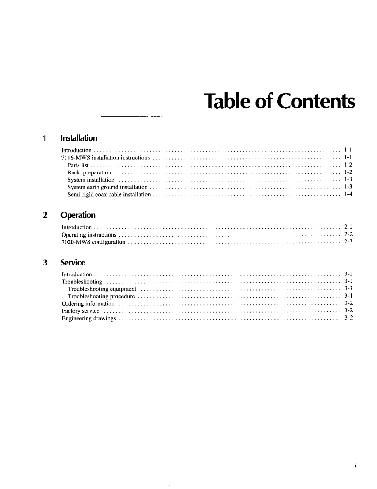
1 Installation
Table of Contents
Introduction
7116.MWS installation instructions
Parts list
Rack preparation
System installation
System earth ground installation
Semi-rigid coax cable installation
2
Operation
Introduction ...................
Operating instructions ...........
7020-MWS configuration ........
3 Service
Introduction .._....._....
Troubleshooting
Troubleshooting equipment
Troubleshooting procedure
Ordering information
Factory service
Engineering drawings
.......
.......
.......
.......
.......
.......
.......
.......
.......
.......
......
......
......
......
......
......
......
..........
..........
..........
..........
..........
..........
..........
......
......
......
......
......
......
......
......
......
......
......
......
......
......
I-I
1-I
1-2
1-2
l-3
1-3
1-4
2-1
2-2
2-3
3-l
3-l
3-i
3-l
3-2
3-2
3-2
Page 8

List of Illustrations
1
Figure I-1
Figure l-2
Figure 1-3
2
Figure 2-I
1
Installation
Fastener installation
Mounting kit installation
Cable installation
.....................................................................
.......................................................................
.................................................................. l-3
l-2
1-4
Operation
Tree switching network 2-l
List of Tables
Installation
Table l-l
2
Table 2-l
3
Table 2-1
ii
Model 7116.MWS rack assembly parts l-2
Operation
Model 7001 outputs, memory locations, and commands 2-2
Service
Troubleshooting procedure ,_.,_.__,,,.,,,,..........._.....................,.........._... 3-2
Page 9

Introduction
The Model 7116-MWS 16-Channel Microwave Switch System provides an integrated solution for multiplexed signal routing
of microwave signals at frequencies up to 18GH.z. The Model 71 I6-MWS switch system can be used to test wireless telecom-
munication devices and systems such as cellular phones, cordless phones, pagers, antenna systems, base stations, and other
wireless transmission productions.
It consists of:
- Five 1x4 microwave RF multiplexer switch modules
* A Model 7020.MWS switching card
* A Model 7001 switching mainframe
* An off-line power supply
. Semi-rigid cables
7116-MWS installation instructions
WARNING
The information on the following pages is intended for qualified service personnel only. Do not attempt
these procedures unless you are qualified to do so.
CAUTION
To prevent flexing of the connections and possible damage, ensure that the Model 7020~MWS card is
secured with its thumbscrew to the Model 7001 rear panel, and that the cable assembly is secured with
its two screws to the 7020-MWS card.
l-l
Page 10

Table I-l
Model 7116MWS rack assembly parts
Quantity
Description
Keithley
part number
Function
2 Bracket, rear support
4 I O-32 Kept””
4 IO-32 x % Phillips pan head screw
8 Fastener, captive nut
8 IO-32 x % Phillips pa” head screw
I IO-32 x % Phillips pa” head sems screw 10-32.x3/8 PPHSEM
2 Semi-rigid cable
2 Semi-rigid cable
BR-21 Attaches chassis rear to rear rack rails.
I O-32 KEPNUT Attaches rear support brackets to chassis.
10-32x3/8 PPM
FA-148 Attachcs rear support brackets and front
10-32x5/8 PPH
panel to rails.
Connect ground cable to earth ground.
7116-307-I
7116-307-2
Parts list
Table l-l lists the parts supplied with the Model 71 I6-MWS 16.Channel Microwave Switch System.
Rack preparation
I. Select a location in the rack. The assembly will take up to 5% inches of vertical space
2. Hold up the system at the selected location in the rack. The four slotted mounting holes in the front panel dictate the location
of the captive ““t fasteners on the front rack rails. Mark where the fasteners are to be installed.
3. Referring to Figure I- I, install four fasteners so the captive nuts are located behind the appropriate holes on the front rack rails.
.J
Figure 1-I
Fastener installation
Front Rack
Rail
1-2
Page 11

System installation
Refer to Figure l-2 to install the chassis and support brackets in the rack,
24”
10-32x 318 PP
&
#IO-32 KEynut
Figure Z-2
Mounting kit
installation
I, Loosely attach lhe rear support brackets to the chassis with kepnuts and lo-32 x % screws.
2. Position the chassis assembly in the rack to adjust the support brackets, and note the location for the captive nul fasteners
on the rear rack rails.
3. Install four fasteners so the captive nuts arc located behind the appropriate holes on the rear rack rails.
4. Loosely attach the chassis assembly to the front and rear rack rails with 10-32x % saews. Secure the rear support brackets
to the chassis.
5. Tighten all screws.
Power SuppI
WARNING
The Model 7116~MWS must be separately connected to a safety earth ground to maintain protection
against possible shock hazard. Failure to connect the unit to a safety earth ground may result in personal injury or death due to an electric shock.
System earth ground installation
1, Remove all power from the system.
2. Connect the loose end of the six foot green/yellow ground cable to a quality ground located within your facility using the
#I 0 screw provided.
1-3
Page 12

Semi-rigid coax cable installation
WARNING
Contact with exposed conductors carrying RF power may cause burns. Place protective caps on all un-
used switch inputs. All cables and connectors should be properly mated and shielded.
I. Remove all power from the system.
2 Remove the plastic protective caps from the switch inputs shown in Figure l-3. Leave Lhc olher caps on. Saw Lhc removed
caps for l’ulurc USC. Conneci the cables to the switches as shown in Figure l-3 and tightcn using a VIS inch wrench, to 7. IO
in.-lb.
Figure Z-3
Cable installation
1-4
Page 13

2
Operation
Introduction
The Model 7116-MWS system is a 16.input microwave mulliplexer. Sixteen inputs are achieved by connecting five single-pole,
four-throw switches together forming a tree switching network as shown in Figure 2-l.
Figure 2-z
Tree switching network
2-l
Page 14

Operation
Operating instructions
To selecl an input channel, the Model 7001 must close tw” switches at the same time. Table 2-l lists which Model 7020.MWS
digital outputs must be activated to select each respective RF input. The table also shows 7001 channels used to sclcct the inputs.
Table 2-Z
Model 7001 channels und memory locutionsfor lx16 multiplexer
7020-MWS Digital Outputs
7116-MW!
Input
Ch. 1
Ch. 2
Ch. 3
Ch. 4
Bank A Bank B
OUT 1
OUT 2
OUT 3
OUT 4
Bank C Bank D
OUT 21 1!1,1!21
OUT 21 I !2,1!21
OUT 21 1!3,1!21
OUT 21 1!4,1!21
T
Channels
7001
7001
Memory
Location
Ml
M2
M3
M4
--
7116-MM
7s
Relays
Kl.K5
Ch. 5
Ch. 6
Ch. 7
Ch. 8
Ch. 9
Ch. 10
Ch. 11
Ch. 12
Ch. 13
Ch. 14
Ch. 15
Ch. 16
Outpul patterns for each input are stored in the Model 7001 memory al the factory. The user can call up memory locations to
select each input. For example, calling up memory location 1 selects input 1. Some programming examples are listed below.
In either configuration of the Model 7116.MWS, as one I x I6 multiplexer ol; with the semi-rigidjumper cables
removed, as Jive I x 4 multiplexers, ensure that only one channel
relays are energized simultaneously per bank.
OUT 5
OUT 6
OUT 7
OUT 8
OUT 9
OUT 10
OUT11
OUT 12
OUT 13
OUT 14
OUT 15
OUT 16
OUT 22 1!5,1!22 MS
OUT 22 1!6,1!22
OUT 22 1!7,1!22
OUT 22 I !8,1 !22 MX
OUT 23 1!9,1!23
OUT 23
OUT 23 1!11,1!23
OUT 23 1!12,1!23 Ml2
OUT 24 1!13,1!24
OUT 24
OUT 24 1!15,1!24
OUT 24
NOTE
is
1!10,1!23 Ml0
1!14,1!24 Ml4
1!16,1!24 Ml6
closedper relay, and that no more than two
M6
M7
M9
Ml1
Ml3
Ml5
K2, K5
K3, K5
K4, KS
2-2
For further information on operation and programming, refer to the Models 7001 and 7020 Instrwtion Manuals
Page 15

Operation
Power Limits
The Model 7020-MWS card is a modified version of the Model 7020 Digital I/O Interfacc Card. Among other changes, the output
protection network has hecn removed for greater sink current capacity.
CAUTION
This card is not intended for use in applications other than the Model 7116-MWS system. The 7020.
MWS and 7020 cards are not interchangeable. Damage or unintended operation may result if a Model
7020 is substituted for a 7020-MWS.
NOTE
A hank refer,~ to the
(banks) to accomodate the 40 output channels. The outputs are grouped
Bank A = OUT 1 through OUT 8
Bank B = OUT 9 through OUT 16
Bank C = OUT 17 through OUT 24
Bank D = OUT 25 through OUT 32
Bank E = OUT 33 through OUT 40
internal
IC that is used to drive eight output channels. The card uses five driver ICs
asfollowsfor
each bank:
2-3
Page 16

Operation
2-4
Page 17

3
Service
Introduction
The following paragraphs contain troubleshooting and replacement parts information. Schematic diagrams, and component layout drawings for the Model 7116.MWS chassis arc also included. Refer to Model 7001 and 7020 manuals for further information about these components.
Troubleshooting
WARNING
The information in this section is intended for qualified service personnel only.
may expose you to hazardous voltages that could result in personal injury or death. Do not attempt to
perform these procedures unless you are qualified to do so.
Troubleshooting equipment
The Model 2000 Digital Multimeter is recommended for troubleshooting
Troubleshooting procedure
Table 3-l summarizes the procedure Coor verifying operation of the Model 7116.MWS. Refer to the system schematic and the
chassis wiring diagram (drawing number 7116.051) for component locations.
Some of the procedures
3-1
Page 18

Table 3-I
Troubleshooting procedure
step
2
3
4
5
6
7
8
9
10
11
12
13
14
15
16
17
IX
YrE: see
Item/component
Chassis
I
Kl-KS, pin COM
KI pin I, K5 pin I
KI pin 2, K5 pin 1
Kl pin 3, K5 pin I
KI pin 4, K5 pin I
K2pinl,K5pin2
K2 pin 2, K5 pin 2
K2 pin 3, K5 pin 2
K2 pin 4, K5 pin 2
K3pinl,K5pin3
K3 pin 2, K5 pin 3
K3 pin 3, K5 pin 3
K3 pin 4, K5 pin 3
K4pin l,K5pin4
K4 pin 2, K5 pin 4
K4 pin 3, K5 pin 4
K4 pin 4, K5 pin 4
ble 2-1 for information on clos
T
Required condition
4
< 29VDC
< I .5v
< 1.5v
< 1.5v
< I .5v
< 1.5v
< 1.5v
< 1.5v
< 1.5v
< 1.5v
< 1.5v
< 1.5v
< 1.5v
< 1.5v
< 1.5v
< l.SV
< 1.w
channels.
Comment
I
All voltages rcfcrenccd to chassis
Relay coil voltage
Close channel I
Close channel 2
Close channel 3
ClOSC channel 4
Close channel 5
Close channel 6
Close channel 7
Close channel 8
Close channel 9
Close channel 10
Close channel 11
Close channel 12
Close channel 13
Close channel 14
Close channel 15
Close channel 16
Ordering information
To place an order or to obtain information concerning replacement parts, contact your Keithlcy representative or the factory.
When ordering parts, be sure to include the following information:
. Model numbers 7116-MWS, 7020.MWS, and 7001
- Serial number OC the chassis, card, or mainframe
- Part description
* Circuit designation (if applicable)
* Keithley part number
Factory service
If the Model 7116.MWS system must be returned to Keithley for repair, perform the following:
1. Call the Repair department at 1-800-552-I 115 for a Return Material Authorization (RMA) number.
2. Complete the service form at the back of this manual and include it with the card.
3. Carefully pack the card in the original packing carton.
4. Write ATTENTION REPAIR DEPT and the RMA number on the shipping label.
Engineering drawings
The Model 7116.MWS schematic (7116.MWS-406). chassis assembly (7116.050), and chassis wiring (7116.051) drawings
are included on the following pages.
3-2
Page 19

Page 20

Page 21

Page 22

Service Form
Model No.
Serial No.
Date
Name and Telephone No.
Company
List all control settings, dcscribc problem and check boxes that apply to problem.
0 Intermittent
u IEEE failure
m Front panel operational
Display or output (check one)
Ll Drifts
0 Unstable
0 Overload
a Calibration only
0 Data required
(attach any additional sheets as necessary)
Show a block diagram of your measurement system including all instruments connected (whether power is hzned on or not).
Also, describe signal source.
0 Analog output follows display
0 Obvious problem on power-up
m All ranges or functions are bad
n Unable to zero
0 Will not read applied input
u Certificate of calibration required
a Particular range or function bad; specify
0 Batteries and fuses are OK
a Checked all cables
Where is the measurement being performed? (factory, controlled laboratory, out-of-doors, etc.)
What power line voltage is used?
Relative humidity?
Any additional information. (If special modifications have been made by the user, please describe.)
Cther?
Ambient temperature?
“F
Page 23

Keithley Instruments, Inc.
28775 Aurora Road
Cleveland, Ohio 44 I39
 Loading...