

Page 1

Model 708
Switching System
Instruction Manual
Contains Operating and Servicing information
Page 2

WARRANTY
Keithley Instruments, Inc. warrants this product to bc free from defects in material and workmanship for a period of I year from date of
shipment.
Keithley Instruments, Inc. warrants the following items for 90 days from the date of shipment: probes, cables, rechargeable batteries,
diskcttcs, and documentation.
During the warranty period, we will, at our option, either repair or replace any product that proves to be defwtivc.
To cxercisc this warranty, write or call your local Kcithley representative, or contact Keithley headquarters in Cleveland, Ohio. You will
be given prompt assistance and return instructions. Send the product, transportation prepaid, to the indicated service facility. Repairs
will bc made and the product returned, transportation prepaid. Repaired or replaced products xc warranted for the balance of the originel warranty period, or at least 90 days.
LIMITATION OF WARRANTY
This warranty dots not apply to defects resulting from product modification without Kcithley’s express written consent, or misuse of
any product or part. This warranty also does not apply to fuses, software, non-rcchargcablc batteries, damage from batcry lc&agc, 0~
problems arising from normal wear or failure to follow instructions.
THIS WARRANTY IS IN LIEU OF ALL OTHER WARRANTIES, EXPRESSED OR IMPLIED, INCI.UDING ANY IMPLIED
WARRANTY OF MERCHANTABILITY OR FITNESS FOR A PARTICULAR USE. THE REMEDIES PROVIDED HEREIN ARE
BUYER’S SOLE AND EXCLUSIVE REMEDIES.
NEITHER KEITHLEY INSTRUMENTS, INC. NOR ANY OF ITS EMPLOYEES SHALL BE LIABLE FOR ANY DIRECT, INDIRECT, SPECIAL, INCIDENTAL OR CONSEQUENTIAL DAMAGES ARISING OUT OF THE USE OF ITS INSTRUMENTS AND
SOFTWARE EVEN IF KEITHLEY INSTRUMENTS, INC., HAS BEEN ADVISED IN ADVANCE OF THE POSSIBILITY OF
SUCH DAMAGES. SUCH EXCLUDED DAMAGES SHALL INCLUDE, BUT ARE NOT LIMITED TO: COSTS OF REMOVAL
AND INSTALLATION, LOSSES SUSTAINED AS THE RESULT OF INJURY TO ANY PERSON, OR DAMAGE TO PROPERTY.
Keithley Instruments, Inc. - 28775 Aurora Road-Cleveland, OH 44139 - 216-248-0400 - Fax: 216-248-6168 - http://www.keithley.com
Page 3
Model 708 Switching System
Instruction Manual
01996, Keithley Instruments, Inc.
All rights reserved.
Cleveland, Ohio, U.S.A.
Second Printing. lunc 1997
Document Number: 708-90-01 Rev. R
Page 4
Manual Print History
The print history shown below lists the printing dates of all Revisions and Addenda created for this manual. The Revision
Level letter increases alphabetically as the manual undergoes subsequent updates. Addenda, which are relcascd between Revisions, contain important change information that the user should incorporate immediately into the manual. Addenda arc numbered sequentially. When a new Revision is created, all Addenda associated with the previous Revision of lhc manual are
incorporated into the new Revision of the manual. Each new Revision includes a revised copy of this print history page.
Kcvisim
Addendutn A (Dncument Number X18-901 -02)
*ddc”dum A ~““cument Number 708~901-03~.
RWiSi”” B (Ihcumcnt Nunlhcr 7”%9”1~“1).
A (Document Namhcr 708-901-01). ................................................................................... Pcbruary
....................................................................................... Mily ,996
....................................................................................... July 1Wh
.......................................................................................... JU”C ,997
14%
Page 5

Safety Precautions
The following safety precautions should he obsaved before using
this product and any associated instrumcnlation. Although some instruments and accessories would normally be used with non-bazardous voltages, there arc situations where huardous conditions
may bc present.
This product is intended for USC by qualified personnel who rccognirc shock hazards and are familiar with the safety precautions required to avoid possihlc injury. Read Lbc operating information
cardully before using the product.
The types of product users are:
Responsible body is the individual or group responsible for the USC
and maintenance of equipmcnt. and for ensuring that operators are
adequately trained.
Operators use tbc product for its intended function. They most hc
trained in electrical safety procedures and proper use of the inntrument. They must bc protected from electric shock and contacl with
hazardous live circuils.
Maintenance personnel perform routine procedures on the product
to keep it operating, for example. setting tic line voltage or rcplacing consumable materials. Maintenance procedures are described in
the manual. The procedures explicitly state if tbc operator may pw
form them Otherwise, they should be pcrformed only by service
p~IS”“d
Service personnel are trained to work on tivc circuits, and perform
saie installations and repairs of products. Only properly trained ser-
vice personnel may perform installation and service procedures.
Exercise cxtrome caution when a shock hazard is present. Lethal
voltage may be present on cable connector jacks or test fixtures. The
American National Standards Institute (ANSI) states that a shock
hazard exists when voltage levels greater than 30V RMS, 42.4V
peak, or 60VDC are present. A good safety practice is to Expect
that hazardous voltage is present in any unknown circuit beSore
measuring.
Users OS his product must be pro,ecwtt from elcclric shock ia illI
times. The responsible body must c~wrc dun oscr\ xc prcvcwxt
access and/or insutaled from every conneclion point. In some CIISLIS.
connections most bc cxposcd 10 polenlial buman COIIIWI. Product
users in these circunx~mccs must he trained to protect thcmsclvcs
from the risk ofelecLTic shock. If Ihc circuit is capable ofopcmling
al or above 1000 voids, no conductive part of the circuit may be
exposed.
Do not connect switching cards dircclty 10 unbmilcd power circuils.
They arc intended LO be used with impcdancc limilctl sourcc~.
NEVER connect switching cards directly to AC mains. When connccting sources to switching cards. install prolectivc dcviccr 1o tiw
it fault currcn, and votragc to the card.
Bcforc operating an inswument, make sure lbc lint cord is connccl~
cd to a properly grounded power reccpt;~lc. Inspect the connecting
cables, test leads, and jumpers for possible wear. cracks. or breaks
before each use.
For maximum safety. do no, louch ,bc product, tcs, abler. or any
other instruments white power is appticd to the circuil under test.
ALWAYS remove power from the entire test syswm and discharge
any capecitars before: connecting or disconnccdng cabtcs or jumpers, installing or removing switching cards. or making internal
changes, such as installing or removing jumpers.
Do not touch any object that could provide a currcn~ petit to tbc
common side of tbc circuit under wrl or power line (earth) ground.
Always make m~~surcments with dry hands while standing on a
dry, insulated surface capahtc of withslanding the voltapc hciny
measured.
Page 6

Do not exceed the maximum signal levels of the inslrumcnt~ and acccssories, as delined in the specilications and operating information, and as shown on the instrumenl or at tixtorc pan&, or
switching card.
When fuses are used in a product, replace with same type and rating
lor continued proteclion agains, lirc hazard.
Chassis connecLions must only be used as shield connections lo1
measuring circuils, NOT as safely cart,, ground connections.
If you ax using a test fixture, keep the lid closed while powcr is applied to the device under test. Safe operation requires the use of a
lid intcll”ck.
Ifa @ ” LL~CW is prcscnt, connect it to safely earl,, ground using the
wire recommended in Ihe user documentation.
The A ! symbol on an instrument indicates Ihat the user should rcfcr t” the upcrating instructions located in the manual.
Then
symbol on an instrument shows Iha, it can source or me&
sure 1000 dolts or more. including the combincd effect of normal
and commrln mode ““Itages. “se standard safety precautions LO
avoid personal contact with thcsc voltages.
The WARNING heading in a manual explains dangers that might
result in personal injury or death. Always read Lhe associated information wry carefully before performing the indicated procedure.
Instrumentation and a~~~~sories shall not be connected LO humans.
Beiore performing any maintenance, disconnecl Lhc lint cord and
all test cables.
TII maintain protection from electric shock and fire, rcplaccmcnt
components in mains circuits, including the power ~ransCormer, lest
Icads, and input jacks, must be purchased from Keithley lnstrummts. Standard fuses, wilh applicable national safely approvals,
may hc used if the rating and type are the same. Other components
that are not salety related may be purchased from other suppliers as
long as they are equivalent to the original component. (Note that selcclcd parts should bc purchased only through Keithley instruments
to maintain accuracy and funclionalily of the product.) If you am
unsure about the applicability of a replacement componen,, call II
Keithley Instruments oftice for informalion.
To clean the instrument, USC a damp cloth or mild, water based
cleaner. Clean the exterior or Lhe insLIumcnt only. Do not apply
cleaner directly to the instnun~nl or allow liquids to enter or spill
on the inslrument.
The CAUTION heading in a manual explains hands tia~ could
damage the instrument. Such damage may invalidate the warranty.
Page 7
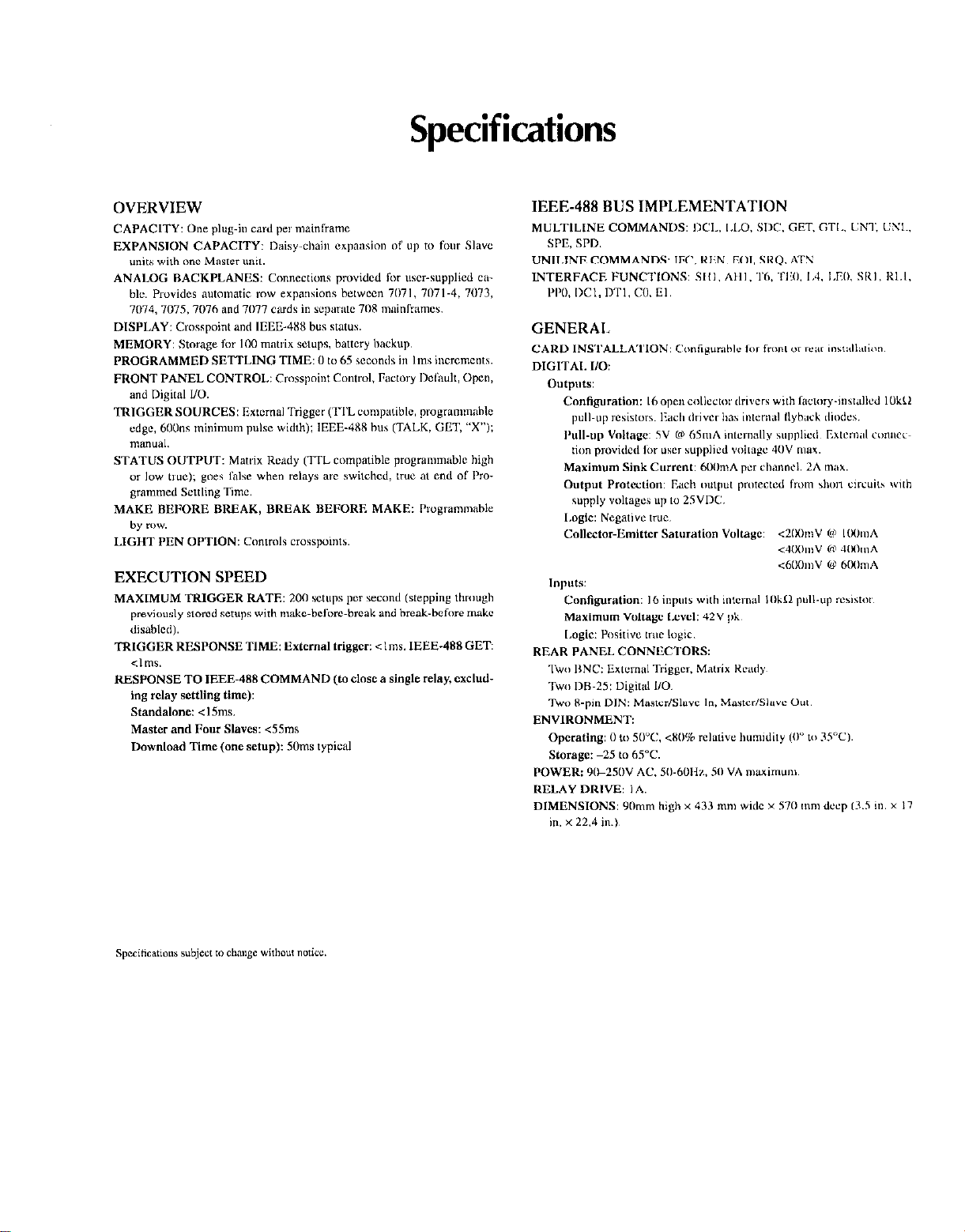
Specifications
Page 8
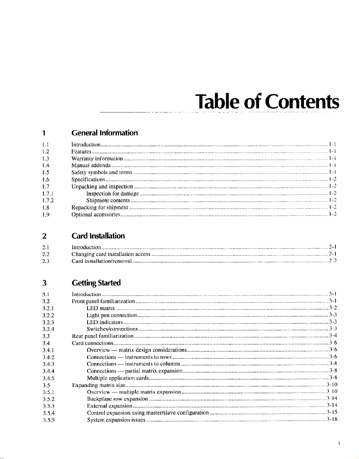
Table of Contents
1
1.1
1.2
1.3
1.4
1.5
1.6
1.7
1.7.1
1.7.2
1.X
1.9
General information
Introduction.. ........................................................................................................................................................ I I
Features ................................................................................................................................................................ I I
Warranty information
Manual addenda
Safety symbols and tams I .................................................................................................................................... I
Specifications ....................................................................................................................................................... I-2
Unpacking and inspection.. .................................................................................................................................. I-?
Inspection ror damage
Shipment contents
Repacking for shipment ....................................................................................................................................... I-2
Optional acCeSSorieS.. ........................................................................................................................................... I-2
...................................................................................................................................................
2 Card Installation
2.1
2.2
2.3
3
3.1
3.2
3.2.1
3.2.2
3.2.3
3.2.4
3.3
3.4
3.4.1
3.4.2
3.4.3
3.4.4
3.4.5
3.5
3.5.1
3.5.2
3.5.3
3.5.4
3.5.5
Introduction ..........................................................................................................................................................
Changing card installation access
.....................................................................................................................................
Card ~nstallatlonlremoval..
Getting Started
Introduction.. ........................................................................................................................................................ 3. I
Front panel famdmnzatlon.. ..................................................................................................................................... 3 -I
LED matrix ................................................................................................................................................
Light pen connection.. ................................................................................................................................ 3-3
LED indicators ........................................................................................................................................... 3-3
Switches/connections.. ...............................................................................................................................
Rear panel familiarization.. ..................................................................................................................................
Card connections.. ................................................................................................................................................ 3-6
Overview - matrix design considerations ................................................................................................
Connections - mstruments to rows
ConnectIons - mstmments to columns ....................................................................................................
Connections -partial matrix expansion ................................................................................................... 3-X
Multiple application cards .......................................................................................................................... 3-8
Expandmg matrix SIX.. ......................................................................................................................................
Overview ~ multiple matrix expansion..
Backplane row expansion ........................................................................................................................ 3- I4
External expansion ................................................................................................................................... 3- 14
Control expansion using master/slave configuration ...............................................................................
System expansion issues. .........................................................................................................................
,,
...........................................................................................................................................
................................................................................................................................
......................................................................................................................................
....................................................................................................................... .2-l
.........................................................................................................
...............................................................................................
I -I
I I
I-2
I-2
2-l
2-2
3-2
3-3
3-4
3-h
.3-6
3-X
3.10
.3 IO
3- I.5
3.18
Page 9
3.5.6
3.5.7
35.8
3.6
3.6.1
3.6.2
3.6.3
3.6.4
Documenting system configuration
Analog backplane cable construction.
Sample expanded matrices
Bask? watching overview
Power-up..
Selecting make/break and break/make rows
Modifying a relay setup
Storing relay setup and applying setup to relays
................................................................................................................................................
......................................................................................................................
..................................................................................................................................
...........................................................................................................................
.........................................................................................................
.....................................................................................................
............................................................................................
.....................................................................................
3.18
3.20
3.20
3.24
3-24
3.24
3.24
3.24
4
4.1
4.2
4.3
4.3. I
4.3.2
4.3.3
4.3.4
4.3.5
4.4
4.4.1
4.4.2
4.4.3
4.4.4
4.5
4.5. I
4.52
4.6
4.6. I
4.6.2
4.6.3
4.6.4
4.6.5
4.6.6
4.6.7
4.6.8
4.7
4.7.1
4.7.2
4.8
4.x.1
4.X.2
4.8.3
4.8.4
4.8.S
4.9
Operation
Introduction..
Setup date paths..
Power-up procedure..
Display.. ...............................................................................................................................................................
Crosspoint display
Operation control
Selecting switching parameters .........................................................................................................................
Triggering ..........................................................................................................................................................
External trigger input
Matrix ready output
IEEE-48X bus triggering
Reset
..................................................................................................................................................................
........................................................................................................................................................
.................................................................................................................................................
...........................................................................................................................................
Line power connections
Power switch..
Power-up self-test and error condltlons..
Power-up c”nCigurati”n
Master/slave power-up ...............................................................................................................................
Error LED
IEEE-4X8 statns indicators
Crosspoint display LEDs ...........................................................................................................................
Light pen
Modifying..
Copying ......................................................................................................................................................
Digital I/O ports..
External
Matrix ready “utput
Stand-alonc
IEEE-488
Hardware relay
Self-test.. ..................................................................................................................................................
Factory delaults .......................................................................................................................................
Programmed
Make/break
Sources.. ...................................................................................................................................................
Overnm
............................................................................................................................................
..................................................................................................................................................
....................................................................................................................................................
...............................................................................................................................................
................................................................................................................................................
.................................................................................................................................................
trigger.. ........................................................................................................................................
and master/slave
bus address.. ............................................................................................................................
settling times ..................................................................................................................
settling times ......................................................................................................................
and break/make rows ...........................................................................................................
conditions
.............................................................................................................................
.....................................................................................................
.............................................................................................................................
........................................................................................................................
.......................................................................................................................................
...................................................................................................................................
....................................
..................................................................................................................................
...............................................................................................................................
.................................................................................................................................
..........................................................................................................................
. ...............................................................................
4 -I
4-l
4-2
4-2
4-2
4-2
4-3
4-3
4.4
4-4
4-4
4-S
4-S
4-6
4-6
4-h
4-7
4-7
4-X
4-X
4-9
4.10
4.10
4.10
4.10
4.10
4-l I
4-l I
4 -I I
4-12
4.12
4.14
4.14
4.15
4.15
5
5.1
5.2
5.3
ii
IEEE-488 Programming
Introduction ..........................................................................................................................................................
IEEE-488 quick
Bus cable connections ..........................................................................................................................................
start.. ..........................................................................................................................................
5-l
5-l
5.3
Page 10
5.4
5.5
5.6
5.7
5.7. I
5.7.2
5.7.3
5.7.4
5.8
5.8. I
5.8.2
5.8.3
5.8.4
5.8.5
5.8.6
5.x.7
5.X.X
5.x.9
5.9
5.9.1
5.9.2
5.9.3
5.9.4
5.9.5
5.9.6
5.9.7
5.9.8
5.9.9
5.9.10
5.9.11
5.9.12
5.9.13
5.9.14
5.9. IS
59.16
5.9.17
5.9.18
5.9.19
S.9.20
5.9.21
5.9.22
5.9.23
5.9.24
5.9.25
5.9.26
5.10
5.1 I
Interface function codes
Primary address programming.. ...........................................................................................................................
QuickBASIC programming .................................................................................................................................
Indicator and c”ntrol aspects “f IEEE-488
Error LED ..................................................................................................................................................
Stetus indicators .........................................................................................................................................
I,OCAL/DIGITAL I/O key..
Concurrent front panel and bus operation
Gcncral bus command pmgramming
Ovcrvicw.. ..................................................................................................................................................
REN (remote enable) .................................................................................................................................
IFC (intcrfacc clear) .................................................................................................................................
LLO (local lockout)
GTL, (go t” local) .....................................................................................................................................
DCL (dcvicc clear). ..................................................................................................................................
SDC (selective dcvicc clear)
GET (group execute trigger)
SPE, SPD (serial polling)
Device-depcndcnt command (DDC)
-0vcrvicw ..................................................................................................................................................
A . External trigger ................................................................................................................................
B - Matrix ready ....................................................................................................................................
c - Close crosspoint ..............................................................................................................................
D - Digital Output
E-Edit pointer..
F - Enable/disable triggers..
G - Data l’ormat
I -Insert blank setup..
J -Self-test..
K . EOI and hold-off.. ...........................................................................................................................
L - Download setups
M - SRQ and serial poll byte
N ~ Open crosspoint..
0 - Digital output
P - Clear crosspoints
Q - Delete setup
R -Restore defaults
S - Programmed settling time..
T - Trigger
u . status..
V - Make/Break
W -Break/Make..
X - Exccutc
Y - Terminator..
z - copy setup
Relay command combinations
Timing conslderatmns ........................................................................................................................................
.......................................................................................................................................
“pcration ..........................................................................................
......................................................................................................................
..................................................................................................
...................................................................................................................
.................................................................................................................................
.................................................................................................................... 5~ IO
...................................................................................................................
.........................................................................................................................
programming.. .........................................................................................
..................................................................................................................................
....................................................................................................................................
...................................................................................................................
......................................................................................................................................
............................................................................................................................
...........................................................................................................................................
..............................................................................................................................
................................................................................................................. S-26
.............................................................................................................................
..................................................................................................................................
..............................................................................................................................
.....................................................................................................................................
...............................................................................................................................
.............................................................................................................. S-30
.............................................................................................................................................
..............................................................................................................................................
.....................................................................................................................................
..................................................................................................................................
.............................................................................................................................................
.....................................................................................................................................
.......................................................................................................................................
...........................................................................................................................
5-S
5-S
5-6
S-7
s-7
S-X
S-9
S-LJ
S-<J
S-9
5.‘)
S-IO
S-10
5 -10
s-10
.S~ IO
5~ 10
S-I I
5-l I
5.15
S- I6
5 -I 7
S-17
S-IX
5 I8
5 I9
S-24
5-24
S-24
S-25
S-28
S-28
S-29
S-29
S-30
S-3 I
5-32
S-36
S-37
5-38
S-38
s-39
S-40
s-41
6
6.1
6.2
6.3
Principles of Operation
Introduction..
Overview ..............................................................................................................................................................
Microcomputer .....................................................................................................................................................
........................................................................................................................................................
h-l
6-l
6-2
Page 11
6.3. I
6.3.2
6.3.3
6.4
6.4.1
6.4.2
6.5
6.5. I
h.S.2
65.3
6.5.4
6.6
6.7
6.7.1
6.7.2
6.8
6.9
6.10
.................................................................................................................................................
Reset c,rcu,t
Address decoding
Memory ......................................................................................................................................................
Relay control c,rcu,try .........................................................................................................................................
Switching card interface ............................................................................................................................
Switching card logic ..................................................................................................................................
Display crcutry
Display data .............................................................................................................................................
Front pilncl keys .......................................................................................................................................
Display interface ...........................................................................................................................
Refresh display/read keyboard ................................................................................................................
Light pen interface.. ...........................................................................................................................................
Master/slave arcutry
Serial cOmmu”lcat*“” ..............................................................................................................................
Control signals .........................................................................................................................................
Digital I/O ..........................................................................................................................................................
IEEE-48X bus interface.. ....................................................................................................................................
Power supplies.. .................................................................................................................................................
.......................................................................................................................................
..................................................................................................................................................
........... 6-l I
........................................................................................................................................
6-3
6-3
6-3
6-4
6-4
6-6
6-8
6-l I
6-11
6 -I I
6-12
6-13
h-13
h- I4
6 I4
6.14
6.14
7
7.1
7.2
7.3
7.4
7.5
7.6
7.7
7.8
7.9
7.9. I
7.9.2
7.9.3
7.9.4
7.9.5
7.9.6
7.10
8
8.1
8.2
8.3
8.4
8.5
Maintenance
Introduction.. ........................................................................................................................................................
Fixed rack mstallatmn.
Cover removal .....................................................................................................................................................
Fuse replaccmcnt .................................................................................................................................................
Battery replacement
Digital I/O power selection (jumper W 101)
Disassembly .........................................................................................................................................................
Static sensitive devices ........................................................................................................................................
Switching System troubleshooting ....................................................................................................................
Handling and cleaning .......................................................................................................................................
........................................................................................................................................... 7-l
.............................................................................................................................................
........................................................................................................ 7-7
............................................................
Recommended tat equipment..
Power-up selGtest
Power supply checks ................................................................................................................................
Mother board checks ................................................................................................................................
Display checks.. .......................................................................................................................................
Using an extender card ............................................................................................................................
....................................................................................................................................
..................................................
.
7-l
7-4
7-S
7-h
7-X
7-8
7-10
7 IO
7 -10
7-l I
7.11
7- I5
7 I5
7 I5
Replaceable Parts
Introduction ..........................................................................................................................................................
Parts lists
Ordering information
Factory service .....................................................................................................................................................
Component layouts and schematics
..............................................................................................................................................................
...........................................................................................................................................
.....................................................................................................................
8-l
8-l
8-l
8-l
8 -I
A Card Configuration Worksheet
8
B.I
8.2
iv
I/O Connections
Typical output connection schemes ,.,,..,.......................,.......................,.....................,,,...................................... B-l
Typical input connection scheme ,,,,,.,..,............................................,.........................,,...................................... B-2
Page 12
C
C.I
c.2
C.3
c.3.1
C.3.2
c.3.3
c.4
c.4. I
C.4.2
c.4.3
c.4.4
c.4.5
C.4.6
c.4.7
C.4.8
C.5
IEEE-488 Bus Overview
Introduclion..
Bus description.. ..................................................................................................................................................
Bus lines
Data lines.. .................................................................................................................................................
Bus management lines ..............................................................................................................................
Handshake lines
Bus commands.. ..................................................................................................................................................
Unilinc commands ....................................................................................................................................
Universal mulLilinc commands
Intcrhcc Cunction codes ......................................................................................................................................
.......................................................................................................................................................
..............................................................................................................................................................
........................................................................................................................................
.................................................................................................................
commands..
...................................................................................................................................
..............................................................................................................
C-I
C-I
c-3
C-3
C-3
(‘~3
C4
C-J
C-5
C-R
”
Page 13
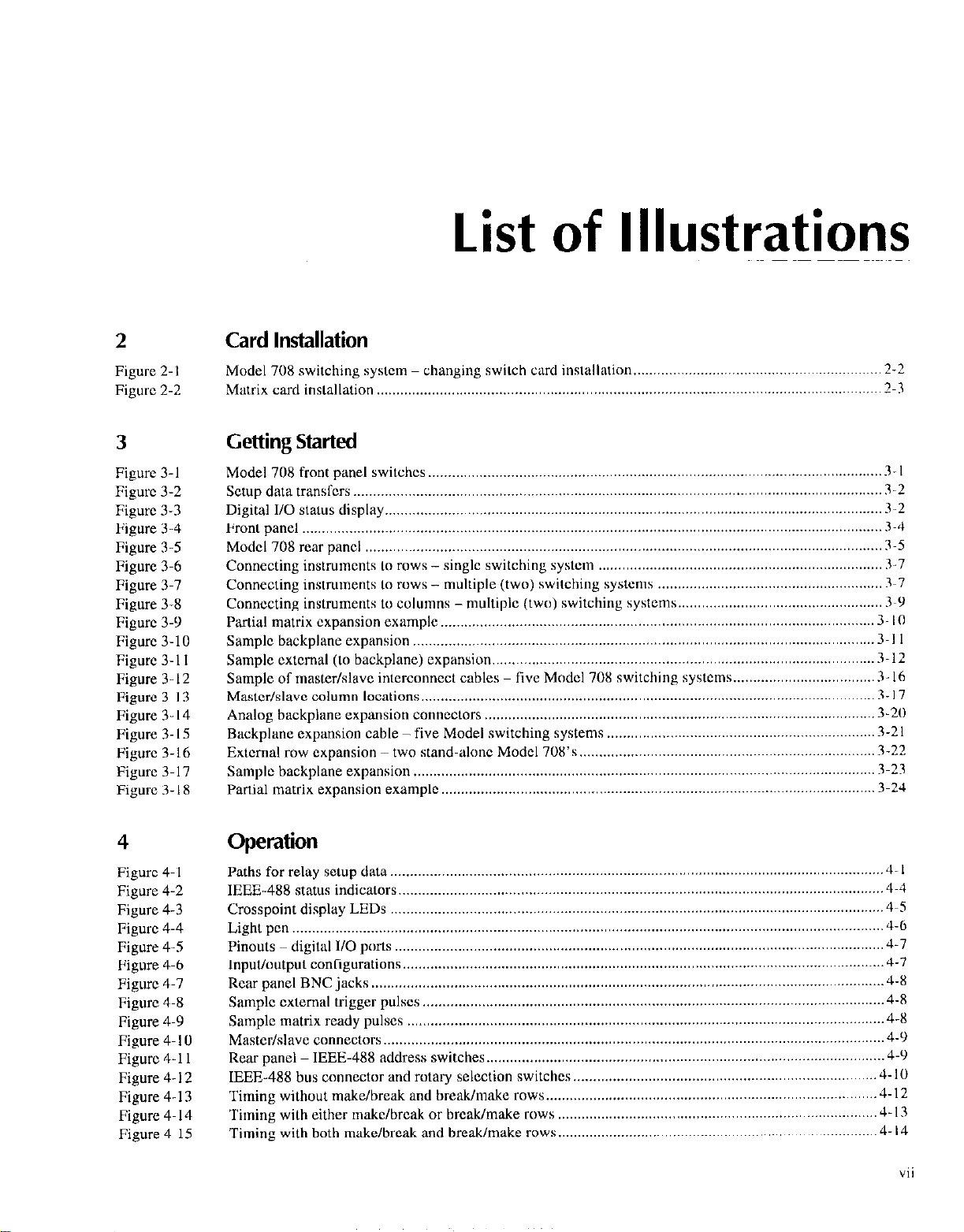
List of Illustrations
2
Figure 2-l
Figure 2-2
3
Figure 3-l
Figure 3-2
Figure 3-3
Figure 3-4
Figure 3-5
Figure 3-6
Figure 3-7
Figure 3-8
Figure 3-9
Figure 3.10
Figure 3-l I
Figure 3. I2
Figure 3-I 3
Figure 3-14
Figure 3-15
Figure 3.16
Figure 3- 17
Figure 3. I8
Card Installation
Model 708 switching system - changing switch card installation ,.............................................................. 2-2
Matrix card installalion .._................................................................................................................... _
T-3
Getting Started
Model 708 front panel switches.. ................................................................................................................
Setup data transfers ......................................................................................................................................
Digital 110 status display.. ............................................................................................................................
Front panel ...................................................................................................................................................
Model 708 rear panel ...................................................................................................................................
Connecting instruments to rows - single switching system
Connecting instruments to rows - multiple (two) switching systems
Connecting instruments t” columns - multiple (two) switching systems..
Partial matrix expansion example.. ...........................................................................................................
Sample backplane expansion ....................................................................................................................
Sample cxtcmal (I” backplane) expansion
Sample of master/slave interconnect cables
Mastcdslave column locations..
Analog backplane expansion connectors
Backplane expansion cable - five Model switching systems
External row expansion two stand-alone Model 708’s..
Sample backplane expansion
Partial matrix expansion example
................................................................................................................. 3 I7
..................................................................................................................... 3-23
..............................................................................................................
.................................................................................................
five Model 708 switching systems..
...................................................................................................
........................................................................ 3.7
.........................................................
.................................................. 3~Y
..................................
....................................................................
......................................................................... 3-22
.3-l
3-2
3-2
3-4
3-5
3-7
.3 IO
.3 -1 I
3-12
3 I6
3-20
3-21
3-24
4
Figure 4. I
Figure 4-2
Figure 4-3
Figure 4-4
Figure 4-S
Figure 4-6
Figure 4-7
Figure 4-8
Figure 4-9
Figure 4. IO
Figure 4-11
Figure 4- I2
Figure 4-13
Figure 4. I4
Figure 4-15
Operation
Paths for relay setup data .............................................................................................................................
IEEE-488 status indicators..
Crosspoint display LEDs
Light pen
Pinouts
1nputl0utput conr,gurat1ons
Rear panel BNC jacks ..................................................................................................................................
Sample cxtemal trigger pulses
Sample matrix ready pulses
Master/sIavc connectors
Rear panel IEEE-488 address switches
IEEE-488 bus connector and rotary selection switches
Timing without make/break
Timing with either makclbrcak or break/make rows
Timing with both make/break and break/make rows
...................................................................................................................................................... 4-6
..
dtgltel I/O ports ............................................................................................................................
.........................................................................................................................
..........................................................................................................................
..........................................................................................................................
.....................................................................................................................
.........................................................................................................................
............................................................................................................................
.....................................................................................................
............................................................................. 4-10
and break/make rows..
.................................................................................
.................................................................................
................................................................................. 4- 14
4 -I
4-4
...4-5
4-7
4.7
4-8
4-8
4-x
...4- 9
4-Y
.4-12
4-13
vii
Page 14
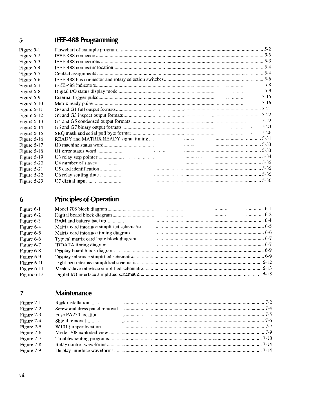
5
Figure 5. I
Figure S-2
Figure S-3
Figure 5-4
Figure 5-5
t’igurc 5-6
Figure 5-7
Figure s-x
Figurc 5-9
Figure 5. IO
Figurc 5-11
Figurc 5-12
Figurc 5. I3
Figure S- I4
Figure 5. IS
Figurc S- I6
Figurc 5-17
Figure 5-18
Figure 5-19
Figure S-20
Figure S-21
Figure 5-22
Figure 5-23
IEEE-488 Programming
Flowchart ol’cxamplc program
IEEE-488 connector..
IEEE-48X connections
IEEE-488 connector location
Contacl assignments ....................................................................................................................................
IEEE-488 bus connector and rotary sclcction
IEEE-488 indicllrors .....................................................................................................................................
Digital I/O status display mode
External trigger pulse..
Matrix reedy pulse
GO and Cl full output formats..
G2 and G3 inspect output Cormats
G4 and G5 condensed output formats
G6
and G7 binary output formats
SRQ mask and serial poll byte format..
KEADY and MATRIX READY signal timing
UO machine status word
Ul error status word ..................................................................................................................................
U3 relay step pointer ..................................................................................................................................
U4 number ot” slaves ..................................................................................................................................
U5 card idcn(lfxatmn ...................................................................................................................................
U6 relay setthng tmx.. ................................................................................................................................
U7 digital input ..........................................................................................................................................
...................................................................................................................................
.................................................................................................................................
...............................................................................................................................
.....................................................................................................................................
....................................................................................................................
........................................................................................................................
switchcs..
....................................................................................................................
.................................................................................................................
.............................................................................................................
....................................................................................................... 5-22
..............................................................................................................
.....................................................................................................
......................................................................................... 5-3 I
.............................................................................................................................
............................................................................. S-6
5-2
5-3
S-3
5-4
5-4
5-8
5-9
5 I5
S- I6
S-21
S-22
S-23
S-26
5-33
5-33
5-34
5-35
5-35
5-3s
5-36
6
Figure 6. I
Figurc 6-2
Figure 6-3
Figure 6-4
Figure 6-S
Figure 6-6
Figure 6-7
Figure 6-X
Figure 6-9
IFigure 6-10
Figure 6. I I
Figure 6. I2
7
Figure 7. I
Figure 7-2
Figure 7-3
Figure 7-4
Figure 7-5
Figure 7-6
Figure 7-7
Figure 7-8
Figure 7-9
Principles of Operation
Model 708 block diagram ............................................................................................................................
Digital board block diagram.. ......................................................................................................................
RAM and battery backup .............................................................................................................................
Matrix card interface simplified schematic
Matrix card interlaw timing diagram..
Typical matrix card logic block diagram
IDDATA timing diagram ............................................................................................................................
Display board block diagram .......................................................................................................................
Display interface simplified schematic
Light pen interface simph~xd schematic
Master/slave interface simphfied schematic
Digital l/O interlace simplified schematic
..
..
.................................................................................................
........................................................................................................ 6-6
.....................................................................................................
........................................................................................................
...................................................................................................
..............................................................................................
.................................................................................................
6 -I
6-2
6-4
6-S
6-7
6-7
6-9
6-9
6.12
6- I3
6 I5
Maintenance
............................................................................................................................................ 7-2
Rack mstalla~~on
Screw and dress panel removal
Fuse FAA250 location..
Shield removal .............................................................................................................................................
W 101 jumper location .................................................................................................................................
Model 708 exploded view
Troubleshooting programs. ........................................................................................................................
Relay control wavcCorms
Display interface waveforms .....................................................................................................................
..................................................................................................................................
....................................................................................................................
...........................................................................................................................
........................................................................................................................... 7-14
7-4
7-5
7-6
7-7
l-9
7 -IO
7 I4
Page 15

8
Figure B-I
Figure B-2
Figure B-3
Figure B-4
Figure B-5
I/O Connections
Digital output, solenoid control
Digital output, r&y control
Digital output, motor control
Digital output, logic dcvicc
Digital input,
....
momtonng micro-swtchcs
........................................................................................................................
...................................................................................................................... B-2
control.. ...........................................................................................................
..................................................................................................................
...................................................................................................
IS- I
IS- I
B-2
B-2
C
Figure C-l
Figure C-2
Figure C-3
IEEE-488 Bus Overview
IEEE-488 bus configuration.
IEEE-48X handshake sequcncc
Command codes..
........................................................................................................................................
.......................................................................................................................
C~?
...................................................................................................................
C3
C-6
ix
Page 16
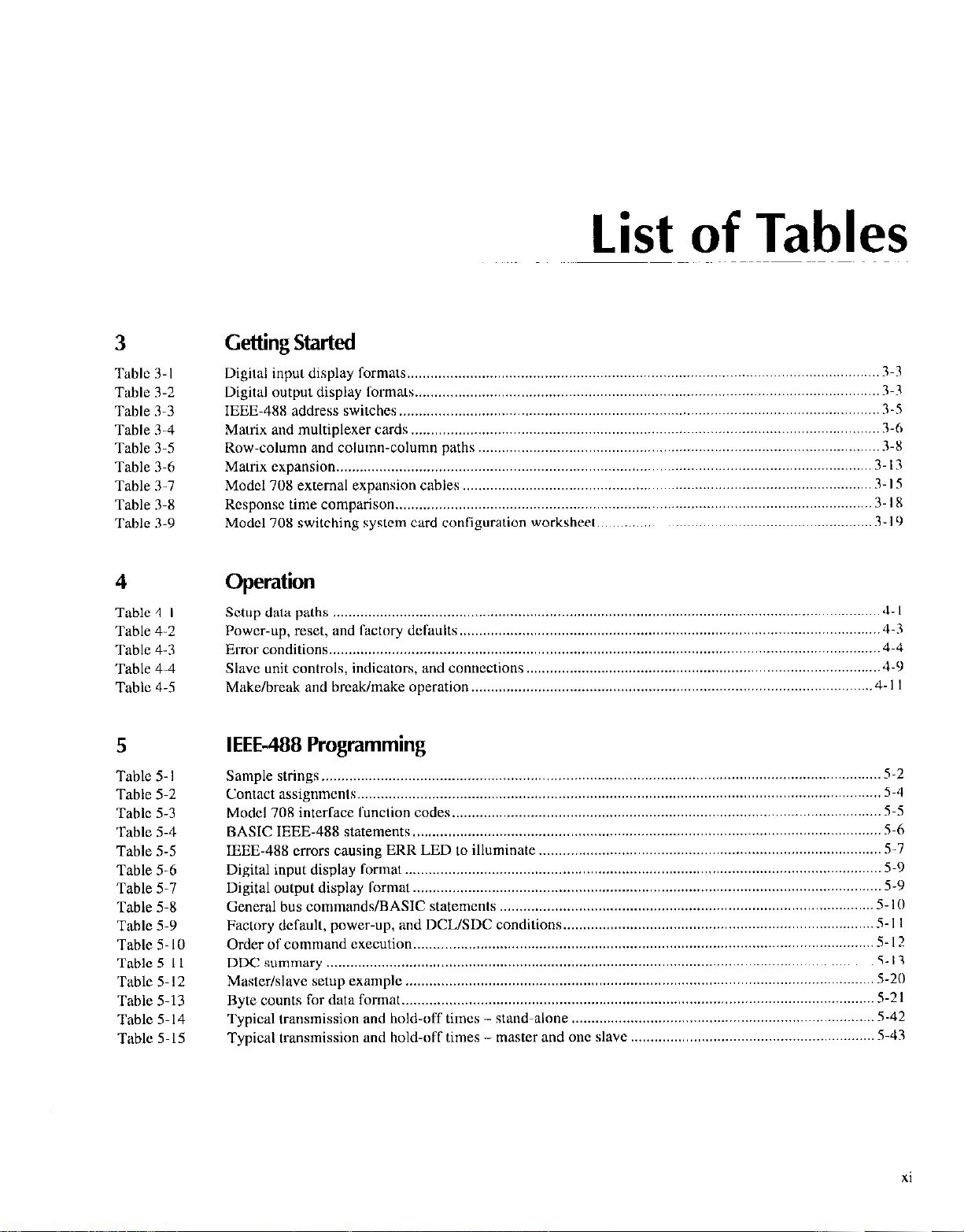
List of Tables
3
Table 3-l
Table 3-2
Table 3-3
Table 3-4
Table 3-S
Table 3-6
Table 3-7
Table 3-X
Table 3-9
Getting Started
Digital input display formats..
Digital output display Ibrmats
IEEE-488 address switches.
Matrix and multiplexer cards
Row-column and column-column paths
Matrix expansion..
Model 708 external expansion cables
Rcsponsc time comparison
Model 708 switching system card configuration worksheet
.......................................................................................................................................
......................................................................................................................
......................................................................................................................
.........................................................................................................................
.......................................................................................................................
......................................................................................................
........................................................................................................
.........................................................................................................................
3-3
3-3
3-5
3-6
3-X
J-13
3 I5
3 IX
......................................................................
3 IY
4 Operation
Table 4. I Setup data paths ...........................................................................................................................................
Table 4-2
Table 4-3
Table 4-4
Table 4-5 Make/break and break/make operation.. ...................................................................................................
5
Table 5. I
Table 5-2
Table 5-3
Table 5-4
Table 5-5
Table S-6
Table 5-7
Table 5-8
Table 5-9
Table 5. IO
Table 5-I I
Tablc 5.12
Table S-13
Table S-14
Table 5.15
Power-up, reset, and factory defaults
Error conditions..
Slave unit controls, indicators, and connections..
........................................................................................................................................
IEEE-488 Programming
Sample strings.. ............................................................................................................................................
Contact assignments .....................................................................................................................................
Model 708 interlace lunclmn codes
BASIC IEEE-48X statements
IEEE-48X errors causing ERR LED to illuminate
Digital input display format..
Digital output display format
General bus commands/BASIC statements
Factory default, power-up,
Order of command execution..
DDC summary ...........................................................................................................................................
Master/slave setup example
Byte counts for data format.. .....................................................................................................................
Typical transnuss~on and hold-off times - stand-alone
Typical transmission and hold-off times - master and
..
.......................................................................................................................
and DCL/SDC conditions..
.......................................................................................................................
..
...........................................................................................................
........................................................................................
.............................................................................................................
.......................................................................................
.......................................................................................................................
.......................................................................................................................
................................................................................................
.............................................................................
...................................................................................................................
..............................................................................
one slave
.............................................................
J- I
J-3
..J~J
4-9
.4 -I I
5-2
5-4
S-5
5-6
S-7
5-9
5-Y
5.10
S-I I
S-I?
5.13
S-20
.5-21
5-42
.5-43
xi
Page 17
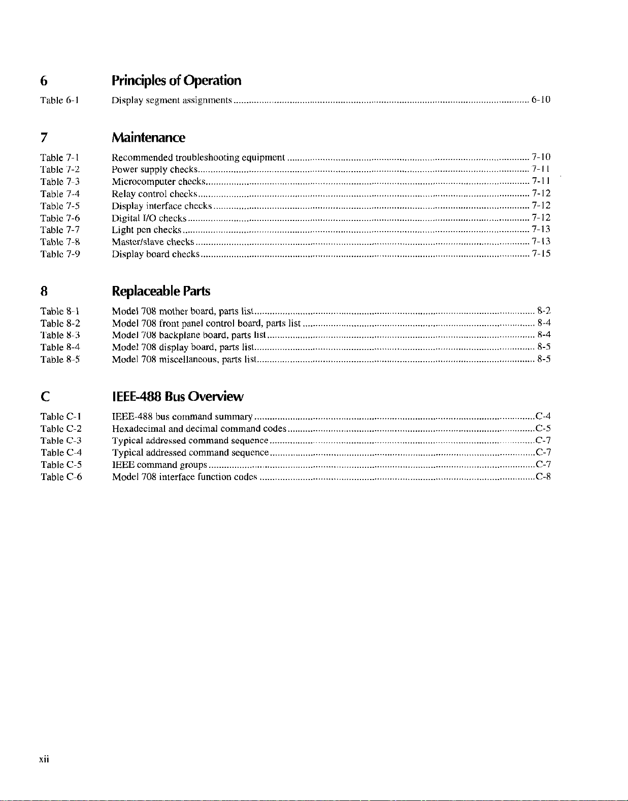
6
Principles of Operation
Table 6-I
Display segment assignments ..__.......__..................................,.............................................................. O-IO
7 Maintenance
Table 7. I
Table 7-2
Table 7-3 Microcomputer checks
Table 7-4
Table 7-5
Table 7-6
Table 7-7
Table 7-8
Table 7-9 Display
Recommended troubleshooting equipment
Power supply checks..
control cheeks.. ................................................................................................................................
Relay
Display interface checks
Digital I/O checks
Light pen checks.
Master/slave checks
hoard checks.. ...............................................................................................................................
................................................................................................................................
...............................................................................................................................
......................................................................................................................................
.......................................................................................................................................
...................................................................................................................................
8 Replaceable Parts
708 mother bead, parts list.. ............................................................................................................
Table S- 1
Table 8-2
Table 8-3
Table X-4
Table 8-5
Model
Model 708 front panel control hoard, pats list
Model 708 backplane board, parts list
Model 708 display hoard, parts list..
Model 70X miscellaneous, parts list
...............................................................................................
............................................................................................................................
...........................................................................................
.........................................................................................................
............................................................................................................
.............................................................................................................
7-10
7-l I
7 -I I
7 I2
7- 12
7- I2
7-13
7- 13
7-15
8-2
8-4
R-4
8-5
8-5
C IEEE-488 Bus Overview
Table C-l
Table C-2
Table C-3
Table C-4
Table C-5
Table C-6
IEEE-48X bus command summary
Hexadecimal and decimal command codes..
Typical addressed command sequence
Typical addressed command sequence
IEEE command
Model 708 interface function codes
groups ................................................................................................................................
..............................................................................................................
...............................................................................................
........................................................................................................
........................................................................................................
............................................................................................................
C-4
C-5
C-7
C-7
C-7
C-X
xii
Page 18
General Information
1.1
This section contains general information about the Model
708 Switching System. The Model 708 is designed as a programmable switch for connecting signal paths in II matrix topology. It is for applications requiring a small-scale matrix
(up to 96 crosspoints per mainhxme and 480 crosspoints per
master/slave configuration). Plug-in cards are available for
general and special purpose switching applications.
Introduction
1.2 Features
Key features of the Model 708 Switching System are:
The switching system accepts one 7X7X switching card
(front or rear panel installation).
Digital I/O contained in the switching system (sixteen
inputs and outputs with internal pull-up resistors).
IEEE-488 bus or interactive programming.
Storage of 100 sets of relay setups, which can bc uploaded or downloaded through the IEEE-488 intcrfacc.
An active front panel LED display shows the present relay status, a stored setup, or an editing scratchpad.
High-speed triggering of stored setups.
Makc/Lxeak and hrctimake switching programmable
matrix by rows. Operation is transparent and indcpendent of the relay setup.
- Maximum matrix size of 8 rows by 60 columns (480
crosspoints on one IEEE-488 address with live units
connected in a mastcrlslave configuration).
- Scaled construction, low heat producing design eliminatcs vent holes, which is suitehlc for cleanrooms.
. An optional light pen is available for interactive control
of relays and editing stored relay setups.
1.3 Warranty information
Warranty information is located on the inside from cow-r ot
this manual. Should your Model 70X rcquirc warranty Serb
vice, contact your Kcitblcy rcprcscntativc or an iwtborizcd
repair facility in your arca for furtbcr information.
1.4 Manual addenda
Any improvements orchangcs concerning the switching system or manual will he explained in ;m addendum 1%~ sure 10
note these changes and incorpomtc them into the manual hcfore using or servicing the unit.
1.5
The following symbols and terms may hc found on an instnimcnt or used in this miuwal.
TheA.
should r&r to the opemting instructions located in the instruction manual.
The A. qymhol on an instrument shows that high voltage
may hc present on the terminal(s). USC standard safety precautions to avoid personal contact with tbcse voltages.
The WARNING heading used in this manual cxplains dagers that might result in personal injury or death. Always
read the associated information wry carefully hcforc per-
forming the indicated procedure.
The CAUTION heeding used in this manual explains haz-
ads that could damage the instrument. Such damegc may invalidate the warranty.
Safety symbols and terms
symbol on an instrument indicates that the user
1-I
Page 19
1.6 Specifications
1.9 Optional accessories
Model 708 specifications axe located at the front of this manual. These spccifcations are exclusive “1 matrix card specifications, which arc located in their appropriate instruction
manual.
1.7
1.7.1
Upon receiving the Model 708, carefully unpack the unil and
inspect it for any obvious signs of physical damage. Repon
any damage to the shipping agent immcdiatcly. Save the
original packing carton for possible future shipment. If installing a matrix card at this time, be sure to follow the additional handling precautions explained in the appropriate
matrix card instruction manual.
Unpacking and inspection
Inspection for damage
1.7.2 Shipment contents
The following items arc included with every Model 70X order:
* Model 70X Switching System.
* Model 708 Instruction Manual.
. Fixed rack mount kit (includes mounting hardwax).
* Removable feet (for bench-top use - includes hard-
WWS).
* Additional accessories as ordered.
The following accessories are available for the Model 708.
Adapter and switching matrix cards
Model 7070 Universal Adapter Card - The Model 7070
card installs in the Model 708 and is jumper-sclcctablc for
use cilhcr as a backplane cxtcnder or a breadboard. It has
quick-disconnect screw terminals and IOft. ribbon cables.
Model 7071 General Purpose Matrix Card -The Model
7071 card has 8 rows by 12 columns of three-pole Form A
switching for general purpose applications. It has mass term
minated connectors in addition to quick-disconnect screw
terminals.
Model 7071-4 Dual 4 x 12 General Purpose Matrix Card
-The Model 707 I-4 card has two banks of four signal paths
of three-pole switching. Row and column connections to the
matrix are through 3X-pin mass terminated connectors.
Model 7072 Semiconductor Matrix Card - The Model
7072 card has 2 rows by 12 columns of two-pole Form A for
low cumxt switching, 4 rows by 12 c”lumn~ of two-pole
Form A for general purpose switching, and 2 rows by 12 columns of one-pole Form A for C-V switching. IL has three-lug
triaxial connectors.
Model 7072-HV High Voltage Matrix Card -The Model
7072.HV switches low level, high vollage, and high impcdante signals for semiconductor parametric tests. It has two
low current paths, four general purpose paths, and two C-V
paths. Connections to the matrix are through triax connectors.
1.8 Repacking for shipment
Should it become necessary to return the Model 708 for rcpair, carefully pack the unit in its original packing carton or
the equivalent, and perform the following:
Call the Repair Department at I-800-552-1 115 for a
Repair Authorization (RMA) number.
Advise as to the warranty status of the switching system.
Write ATTENTION REPAIR DEPARTMENT and the
RMA number on the shipping label.
Fill out and include the service form located at the back
of this manual.
l-2
Model 7073 Coaxial Matrix Card - The Model 7073 card
has 8 rows by 12 columns of one-pole FormA switching (up
to 30MHz) for applications with single-ended instruments. It
has BNC connectors.
Model 7074-D Eight 1 x 12 General Purpose Multiplexer
Card - This card has eight banks “I’ one signal path of
three-pole switching. Bank connections are through four 75.
pin mass tenninatcd connectors; row connections are
through one 3X-pin mass terminated connector.
Model 7075 Eight 1 x 12 Two-Pole Multiplexer Card The Model 7075 is a general purpose multiplex switching
card that consists of tight banks of independent 1 x 12 mul-
tiplexer switching. Eight 25.pin D connectors are provided
Sor bank connections and one for row connections.
Page 20

Model 7076 Dual 4 x 12 Two-Pole Matrix Card - The
Model 7076 is a general purpose matrix switching card that
consists of two indcpcndent 4 x 12 switching matrices. Each
matrix has two switched circuits (HI and GUARD). The four
row signal paths ‘ax connected through jumpcrs to the general purpose analog backplane in the Model 708. Conncctions to the matrix arc through standard 25.pin D connectors
for mass termination.
Model 7077 8 x 12 Isolated Coaxial Matrix Card - The
Model 7077 has 8 rows by 12 columns of two-pole Form A
switching for general purpose applications. It has BNC cot)nectars.
Model 7 172 Low Current Matrix Card - The Model 7 172
is for semiconductor I-V and C-V measurements. It is contigurcd in an 8 x 12 matrix of two-pole switching with triax
connectors. An on-board elcctromcter measures offset current.
Model 7173-50 4 x 12 High Frequency Matrix Card This card combines high frequency performance with
excellent DC switching characteristics. It provides 200MHz
bandwidth in a 4x12 matrix configuration. It has BNC
COll”eCt”TS.
Model 7174 8 x 12 Low Current Matrix Card- The Model 7 174 is designed for high pcrfommnce switching 01 I-V
and C-V signals. It has triax connccto~‘s.
Miscellaneous cables and accessories
Model 7007-l Shielded IEEE-488 Cables - The Model
7007-l connects the Model 708 to the IEEE-48X bus using
shielded cables to reduce clcctromagnetic intcrl’crcncc
(EMI). The Model 7007-I is Im (3.3ft) long imtl has im IIMI
shielded IEEE-48X connector at ci~h end. This cable is also
available in a 2111 (6.6ft) length (Model 7007-2).
Model 7051.2 BNC to BNC Cables - The Model 705 I-2
makes connections to cxtcrnal trigger and matrix ready on
the Model 708 rear panel. The Model 705 I-2 is ii St)<> BNC
to BNC cable (RG58C), which is 0.611~ (2ft) long. This cable
is also available in a ISm (5ft) length (Model 70.51-S).
Model 7078.PEN Programming Light Pen ~ The Model
7078.PEN connects to the Model 70X front pancl. It is used
to toggle the states of the LEDs that display crosspoints and
digital l/O. A pen holdcr is included.
Model 8501-l and 8501-2 Trigger Link Cables - The
Model 8501-l and X501-2 contain nn X-pin malt DIN con-
ncctor. The Model 8501 -I is 1111 (3.311) in Icngth. and the
Model X501-2 is 2111 (6.61() in length. Multiple cahlcs arc
used for connecting Model 708 units in a mastcrlslavc con-
figuration through tbc rear panel mesterlslwc connectors.
Now The following backplane expansion component\ xc
availeblc from 3M Corporation.
Digital I/O cables
Model 7075-MTC Standard Cable ~ Standard 3m (IOft)
cable assembly terminated with 25.pin D-sub plugs on both
ends.
CS-400 Cable - 25.pin D-sub plug that will mate to the reccptacles of the card. Solder-cup connections simplify the
building of custom cables.
CS-401 Cable- 25.contact D-sub receptacle that will mate
to the cables terminated with a 25-pin D-sub plug.
CS-590 Cable-Plastic backshell housing for CS-400.
Note: The following two cables are availahlc from 3M Cor-
poration.
8225-7000 (3M) Cable - 25.pin D-sub plug for customized
ribbon cahlc assemblies.
3357.9225 (3M) - Junction shell for 3M X225-7000 D-sub
plug.
Backplane expansion (20 pin cable components)
3365/20 (3M) - 2X AWG ribbon cable rated at >2oOVDC.
3461-001 (3M) - 0. I inch card-cdgc connector with a cur-
rent rating of IA z ZOOVDC (one connector required for
each Model 708).
3448-54 (3M) - Strain relief.
Backplane expansion (SO pin cable components)
3365/50 (3M) - 28 AWG ribbon cahlc rated at >2OOVDC.
3415-OOOl(3M) - 0. I inch card-edge conncxtor with ii cur-
rent rating of IA > 200VDC (one connector required fol
each Model 70X).
3448-54 (3M) - Strain relief.
I-3
Page 21
2
2.1
Installation procedures arc described in this section.
Introduction
WARNING
The procedures in this section are intended for use by qualified service personnel only. Do not perform these
procedures unless qualified to do so.
Failure to recognize and observe normal
safety precautions could result in personal injury or death.
2.2 Changing card installation access
The configuration chosen for each Model 708 Switching
System (front or rear) can simplify connections and shorten
tbc wiring required for each installation. As shipped from the
factory, the unit is configured for rear panel card installation.
With the Model 708 Switching System configured for front
panel card installation, the card and connections can be ac-
ccssed from the front of the rack. Use the following procedure to change the Model 708 conliguration for front or rear
panel card installation.
WARNING
Turn off power from all instrumentation
(including the Model 708 Switching Sys-
Card
tern) and disconnect all power lint
cords. Make sure all power is removed
and stored energy in external circuitry is
discharged prior to changing card installation configuration.
To prevent contamination, handle matrix cards and backplane using lint-free
gloves. If contamination occurs, clean
according to the card’s instruction manual.
I. Remove the card. slot cover. and analog backplane from
the Model 708 Switching System by loosening the
spring-loaded mounting screws (set Figure 2-l 1.
2. Install analog backplane on the Model 708 Swilching
System panel. Make sure the analog backplane c”n”ecm
tar (PlOl5) is inserted complclely inlo its mating cow
nectar. The mating connector will be J IO1 5A for frond
panel card installation and J1015B for rear panel card
installation.
* Front panel cud installation ~ Install
the analog backplane on the rca panel
of the unit.
* Rear panel card installation - Install
the analog backplane on the front pencl
of the unit.
3. Sccurc and ground by tightening the spring-loaded
mounting screws.
Installation
CAUTION
2-l
Page 22
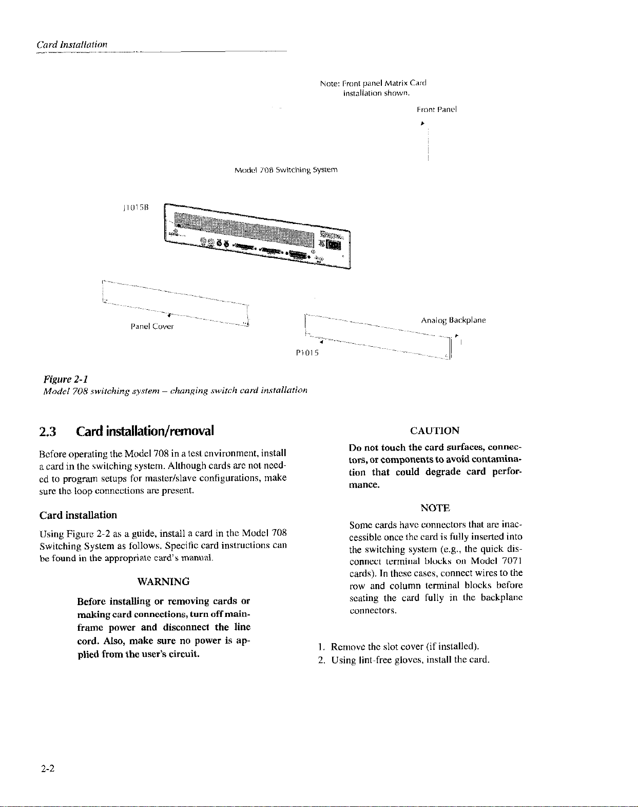
Figure 2-l
Model 708 rwitching s.wtem - changing switch card installation
2.3 Card installation/removal
Before operating the Model 708 in a test environment, install
a card in the switching system. Although cards arc not need-
cd to program setups for master/slave configurations, make
sure the loop connections are present.
Card installation
Using Figure 2-2 as a guide, install a card in the Model 708
Switching System as follows. Specitic card instructions can
be found in the appropriate card’s manual.
WARNING
Before installing or removing cards or
making card connections, turn off mainframe power and disconnect the line
cord. Also, make sure no power is applied from the user’s circuit.
CAUTION
Do not touch the card surfaces, connectors, or components to avoid contamination that could degrade card performance.
NOTE
Some cards have connectors that are inaccessible once the card is fully inserted into
the switching system (e.g., the quick disconnect terminal blocks on Model 7071
cards). In these cases, connect wires to the
row and column terminal blocks before
scaling the card fully in the backplane
connectors.
I. Rcmovc the slot cover (if installed).
2. Using lint-free glows. install the card
2-2
Page 23
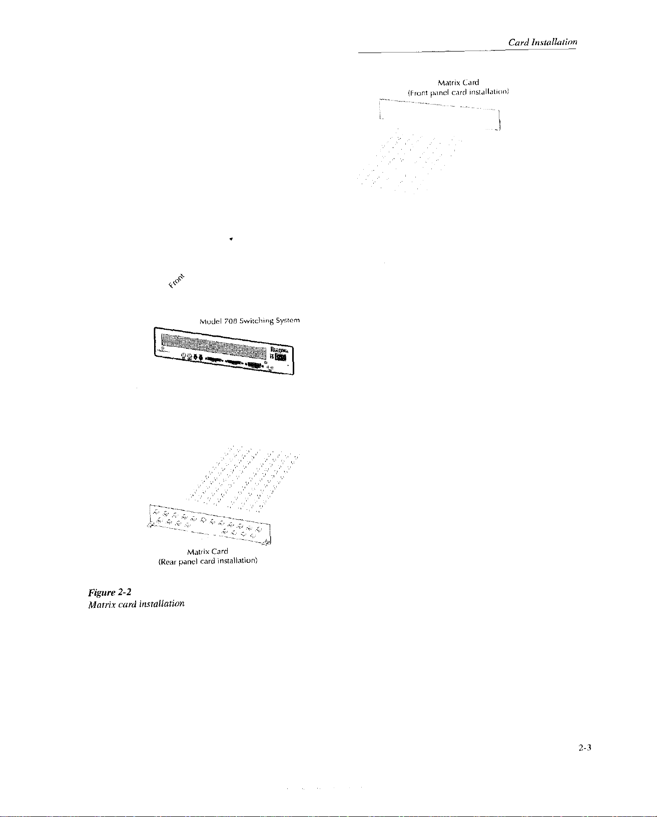
.
lode, ~“8 Switching Syitcm
~~~~~~ ,,ane, card inrtallatiun)
Figure 2-2
Matrix curd installaiion
,,,,’ ,,
.,, ,,, :~
C’,,;!,: :.‘.‘,’
”
,;’ ,, ,,, ,‘~)
,,
t&mix Card
,,,.
”
,, ,’ ‘~ ‘,~
,,
,, ,;’ ,,’ ,’ ‘>
,,, ,,,‘,’ ,‘.’
,’
,,. ,,,‘,’ ,,,
,,
2-3
Page 24

CAUTION
Properly support the card until it is fully
seated in the Model 708’s analog backplane. If the card is not supported until
it is fully seated, it may be damaged by
its own weight.
WARNING
Before installing or removing cards or
making card connections, turn off mainframe power and disconnect the line
cord. Also, make sure no power is applied from the user’s circuit.
3. Pick up the card with both hands (one hand grasping the
handle and the other hand supporting the weight of the
card).
4. Align the card in the Model 708. M&c sure the edges of
the card slide into the card edge guides and the component side of the card is facing op.
5. Slide the card into the Model 70X. Make sure the card is
fully seated in lhe analog backplane.
6. Tighten the spring-loaded mounting screws with a Phil-
ips screwdriver.
WARNING
The mounting screws must be secured to
ensure a proper chassis ground connection between the card and the Model 708
Switching System. Failure to properly
secure this ground connection may result in personal injury or death due to
electric shock.
Card removal
Using Figure 2-2 as a guide, remove a card from the Model
708 Switching System as Coollows. Specilic card instructions
can bc found in the appropriate card’s manual.
CAUTION
Do not touch the card surfaces, connectors, or components to avoid contamination that could degrade card perforlllZi”CC.
NOTE
Some cards have connectors that are inacccssible once the card is fully inserted into
the switching systm (e.g., the quick disconnect terminal blocks on Model 7071
cards). In these cases, remove wires from
the row and column terminal blocks be-
fort fully removing the card from the
backplane connectors.
I. Using lint-free gloves, remove the card.
* Loosen the spring-loaded mounting screws.
* Poll oat the card by its handle (one hand grasping the
handle and the other hand supporting weigh1 of card).
CAUTION
Properly support the card while removing it from the mainframe. An unsupported card may be damaged by its own
weight. Store cards properly. Refer to
the appropriate card manual’s handling
and cleaning precautions for specific instructions.
2-4
2. Install the slot cover (or other card as applicable).
Page 25
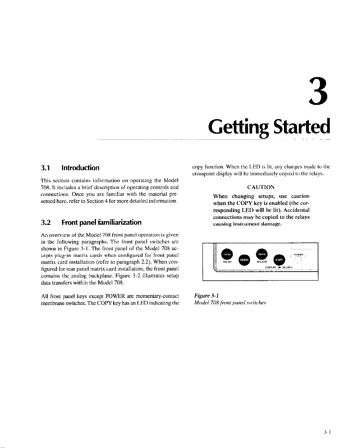
3.1
This section contains information on operating the Model
70X. It includes a brief description of operating controls and
connections. Once you are familiar with the malcrial pre-
sentcd hcrc, refer to Section 4 for more dctailcd information.
3.2
An overview of the Model 708 front panel operation is given
in the following paragraphs. The front panel switches arc
shown in Figure 3. I. The front panel of the Model 708 accepts plug-in matrix cards when contigurcd for front panel
matrix card installation (refer to paragraph 2.2). When configured for rear panel matrix card installation, the front panel
contains the analog backplane. Figure 3-2 illustrates setup
data transfers within the Model 70X.
Introduction
Front panel familiarization
3
Getting Started
copy
function. When the LED is lit, imy
crosspoint display will be immcdiatcly copied 10 lhc relays.
CAUTION
When changing setups, use caution
when the COPY key is enabled (the corresponding LED will be lit). Accidental
connections may be copied to the relsys
causing instrument damage.
L
clw~pc~
made
10
the
All front panel keys except POWER are momentary-contact
membrane switches. The COPY key has an LED indicating the
Figure 3-1
Model 708 from ~mnel swirches
Page 26
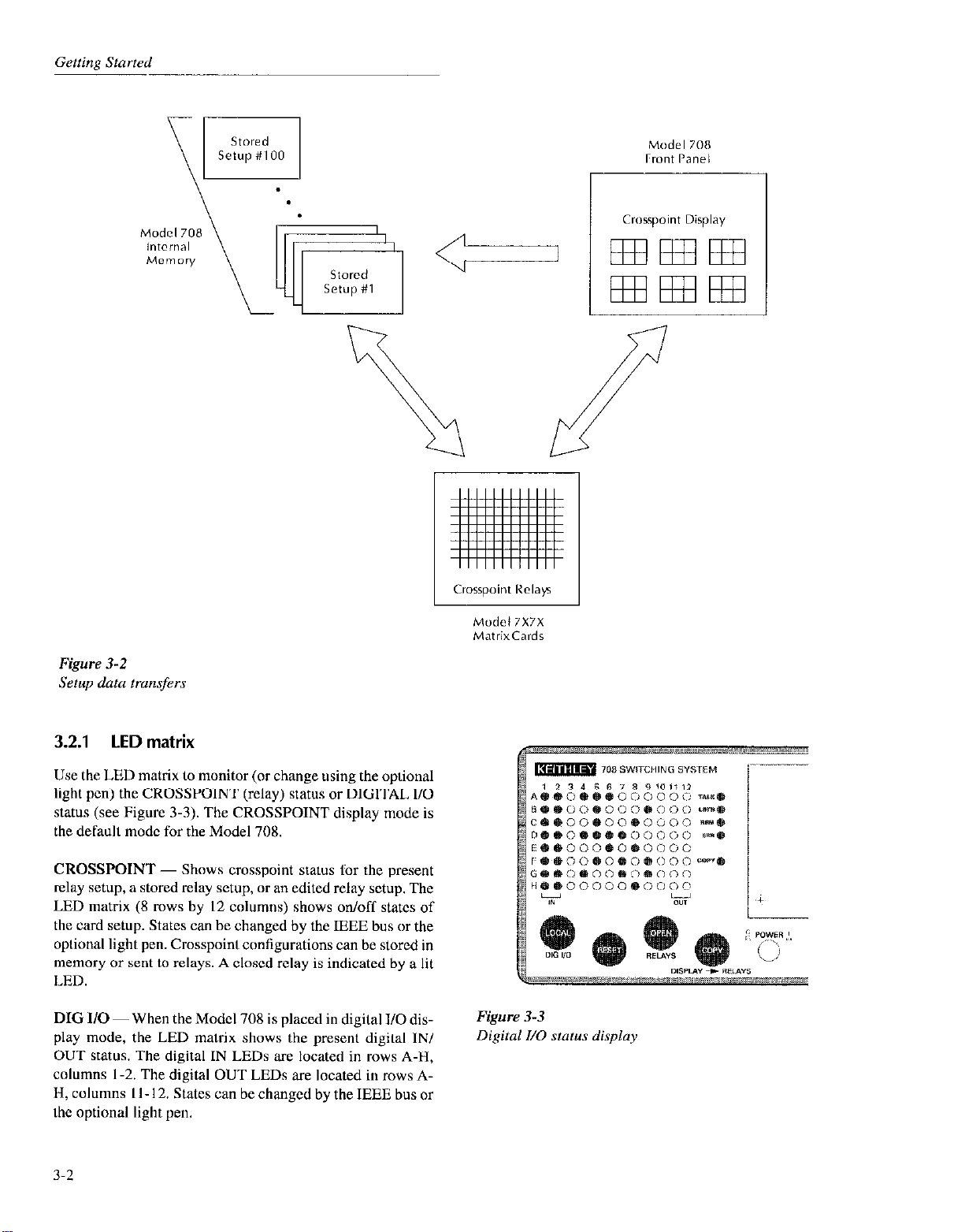
Model 7””
rr”nt Panel
Figure 3-2
Setup data transfers
3.2.1 LED
matrix
Use the LED matrix to monitor (or change using the optional
light pen) the CROSSPOINT (relay) status or DIGITAL I/O
status (see Figure 3-3). The CROSSPOINT display mode is
the default mode for the Model 708.
CROSSPOINT - Shows crosspoint status Sor the present
relay setup, a stored relay setup, or an edited relay setup. The
LED matrix (8 rows by 12 columns) shows on/off states of
the card setup. States can be changed by the IEEE bus or the
optional light pen. Crosspoint configurations can be stored in
memory ot’ sent to relays. A closed relay is indicated by a lit
LED.
DIG I/O ~ When the Model 708 is placed in digital I/O display mode, the LED matrix shows the present digital IN/
OUT status. The digital IN LEDs are located in rows A-H,
columns l-2. The digital OUT LEDs are located in rows AIi, columns I I 12. States can be changed by the IEEE bus or
the optional light pen.
Model 7X7X
MatrixCards
Figure 3-3
Digital I/O status display
3-2
Page 27
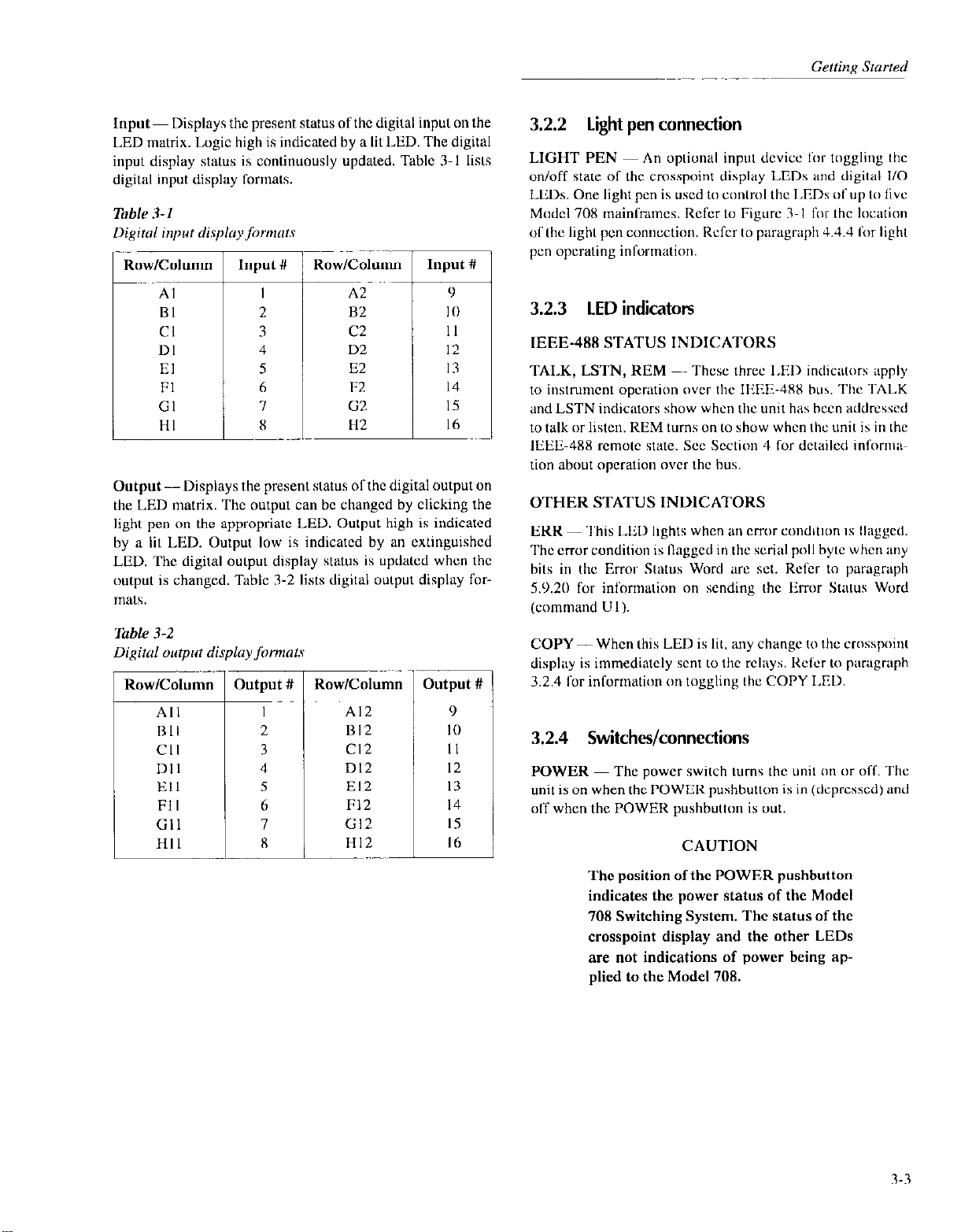
Input-Displays the present status of the digital inpul on the
LED matrix. Logic high is indicated by a lit LED. The digital
input display status is continuously updated. Table 3-l lists
digital input display formats.
Kow/Column
Al
BI
Cl
DI
El
Fl
Gl
HI
Output-Displays the present status of the digital output on
the LED matrix. The output can bc changed by clicking the
light pen on the appropriate LED. Output high is indicated
by a lit LED. Output low is indicated by an extinguished
LED. The digital output display status is updated when the
output is changed. Table 3-2 lists digital output display formats.
Input #
I
2
3
4
5
6
7
8
Row/Column
A2
82
c2
D2
E2
F2
G2
H2
Input #
9
I 0
II
I2
I3
14
I5
I6
3.2.2 light pen connection
LIGHT PEN -An optional input device for toggling Ihe
on/off state of the crosspoint display LEDs and digital I/O
LEDs. One Ii&t pen is uxd to control the I.EDs of up to live
Model 708 mainframes. Rcfcr to Figure 3 I for the location
ofthc light pen connection. Refer to pxagraph 4.4.4 for light
pen operating information.
3.2.3 LED indicators
IEEE-488 STATUS INDICATORS
TAI.K, LSTN, REM - Thcsc three I.ED indicators apply
to instrument operation over the IEEE-JXX bus. The TALK
and LSTN indicators show when the unit has been addrcsscd
to talk or listen. REM turns on to show when the unit is in the
IEEE-488 rcmotc state. Set Section 4 for detailed inform;\+
don about operation over the bus.
OTHER STATUS INDICATORS
ERR ~ This LED lights when an CITOT conditiun is Ilagged.
The error condition is flagged in the serial poll byte when any
bits in the Error Status Word xc set. Refer to paragraph
5.9.20 for inlonnation on sending the Eror Status Word
(command Ul).
Table 3-2
Digital olrtput displayfirmats
I
iow/Column
A12
1312
Cl2
Dl2
El2
F12
Gl2
1
HI2
3utput #
9
IO
II
I2
13
I4
I5
I6
COPY- When this LED is lit, any change to the crosspoint
display is immediately sent LO the rcleys. Rcfcr to paragraph
3.2.4 for information on toggling the COPY LED.
3.2.4 Switches/connections
POWER -The power switch turns the unit on or off. The
unit is on when the POWER pushbutton is in (depressed) and
off when the POWER pushbutton is out.
CAUTION
The position ofthe POWER pushbutton
indicates the power status of the Model
708 Switching System. The status of the
crosspoint display and the other LEDs
are not indications of power being ap-
plied to the Model 708.
R-3
Page 28
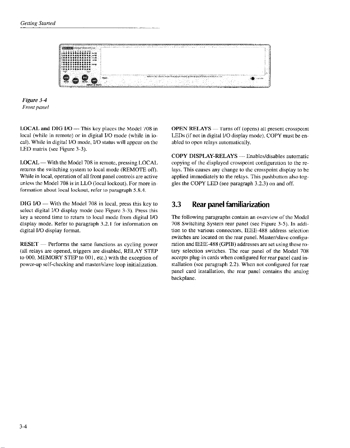
LOCAL and DIG I/O-This key places the Model 708 in
local (while in remote) or in digital I/O mode (while in local). While in digital l/O mode, I/O status will appear on the
LED matrix (see Figure 3-3).
LOCAL- With the Model 70X in remote, pressing LOCAL
returns the switching system to local mode (REMOTE off).
While in local, operation of all front panel controls are active
unless the Model 708 is in LLO (local lockout). For more information about local lockout, refer to paragraph 5.8.4.
OPEN RELAYS ~ Turns off (opens) all prcscnt crosspoint
LEDs (if not in digital l/O display mode). COPY must be enabled to open relays automatically.
COPY DISPLAY-RELAYS - Enables/disables automatic
copying of the displayed crosspoint configuration to the 1%.
lays. This causes any change to the crosspoint display to be
applied immediately to the relays. This pushbutton also toggles the COPY LED (see paragraph 3.2.3) on and off.
DIG I/O-With the Model 708 in local, press this key to
select digital I/O display mode (set Figure 3-3). Press this
key a second time to return to local mode from digital I/O
display mode. Refer to paragraph 3.2. I for information on
digital II0 display format.
RESET ~ Performs the same functions as cycling power
(all relays arc opened, triggers are disabled, RELAY STEP
to 000, MEMORY STEP to 001, etc.) with the exception of
power-up self-checking and master/slave loop initialization.
3.3 Rear panel familiarization
The following paragraphs contain an ovcrview of the Model
708 Switching System rear panel (set Figure 3-5). In addition to the various connectors, IEEE-488 address selection
switches arc located on the rear panel. Masterlslavc configuration and IEEE-488 (GPIB) addresses arc set using these rotary selection switches. The rear panel of the Model 708
accepts plug-in cards when configured for ear panel card installation (see paragraph 2.2). When not conligured for rear
panel card installation, the rear panel contains the analog
backplane.
3-4
Page 29
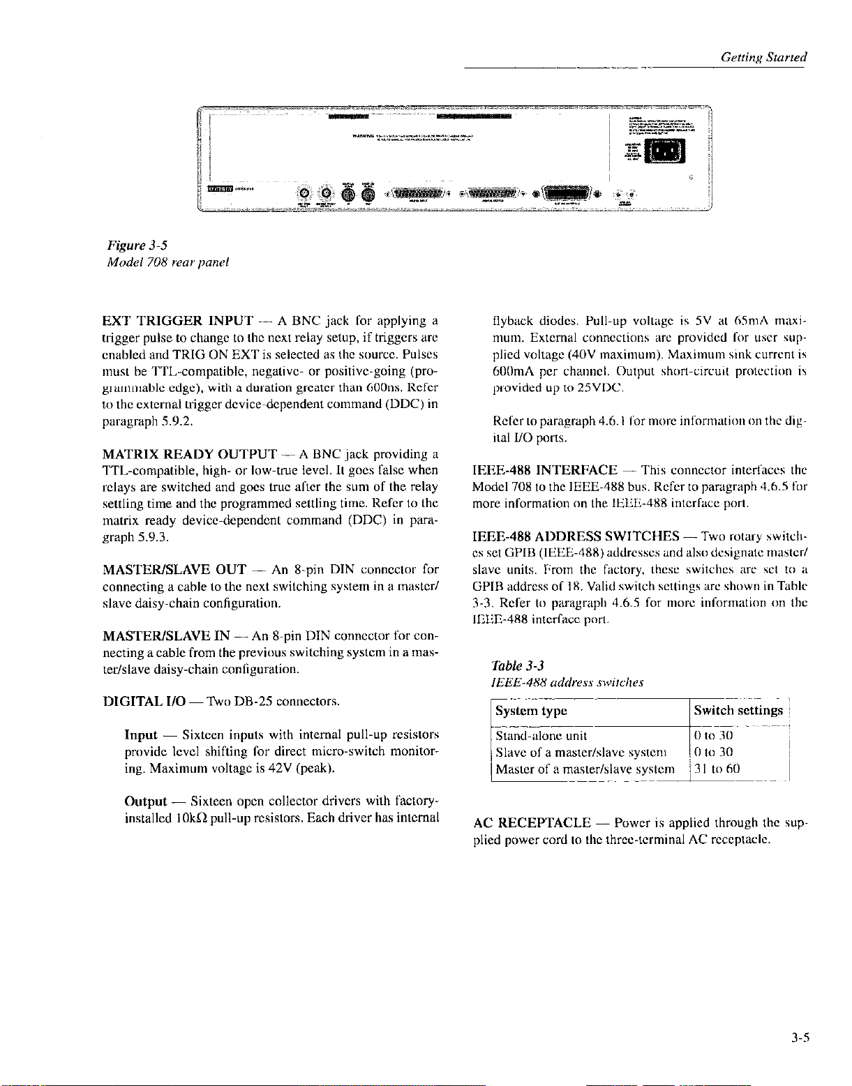
EXT TRIGGER INPUT - A BNC jack for applying a
trigger pulse to chengc to the next relay setup, if triggers xc
cnablcd and TRIG ON EXT is selected as the source. Pulses
must be TTL-compatible, negative or positivc-going (programmablc edge). with a duration grcatcr than 60011s. Rcfcr
to the external trigger device-dependent command (DDC) in
paragraph 5.9.2.
MATRIX READY OUTPUT -A BNC jack providing LL
‘ITL-compatible, high- or low-true level. It goes false when
relays arc switched and goes true after the sum of the relay
settling time and the programmed settling time. Refer to the
matrix ready device-dcpendcnt command (DDC) in pagraph 5.9.3.
MASTER/SLAVE OUT - An X-pin DIN conncClor for
connecting a cable to the next switching system in a master/
slave daisy-chain configuration.
MASTER/SLAVE IN -An g-pin DIN connector for con-
necting a cable from the previous switching system in a mas-
ter/slave daisy-chain conliguration.
DIGITAL I/O ~ Two DB-25 connectors.
Ilyback diodes. Pull-up volt;~gc is 5V at 6SmA maximum. Extcmal connections are provided for user supplied voltage (4OV maximum). Maximum sink current is
600mA per channel. Output short-circuit pmtcctwn IS
provided up to 2SVDC.
Refer to paragraph 4.6. I for more information on the digital I/O ports.
IEEE-488 INTERFACE - This connector interlhccs the
Model 708 to the IEEE-488 bus. Refer to paragraph 4.6.5 lot
more information on the IEIZ488 intcrfxx port.
IEEE-488 ADDRESS SWITCHES -Two rotary \witcI~cs set GPIB (IEEE-488) addresses and also designate IIIBSLCT/
slave units. From the lectory, thcsc switches are set to a
GPIB address of IX. Valid switch settings arc shown in Table
3-3. Rcfcr to paragraph 4.6.5 for more information on the
IEEE-488 interfaacc port
Input - Sixteen inputs with internal pull-up r&stars
provide lcvcl shifting for direct micro-switch monitoring. Maximum voltage is 42V (peak).
Output - Sixteen open collector drivers with factoryinstalled IOkn pull-up resistors. Each driver has intcmal
AC RECEPTACLE - Power is applied through the supplied power cord to the three-terminal AC rcccptaclc.
3-s
Page 30
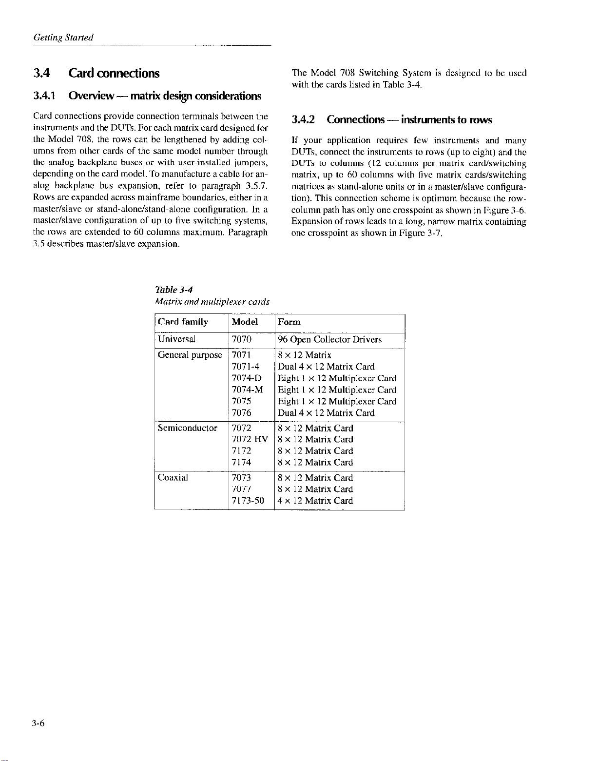
Getting Started
3.4 Card connections
3.4.1 Overview-matrix design considerations
Card connections provide connection terminals between the
instruments and the DUTs. For each matrix card designed for
the Model 70% the rows can bc lengthened by adding col-
umns from other cards of the same model number through
the analog backplane busts or with user-installed jumpers,
depending on the card model. To manufacture a cable for an-
alog backplane bus expansion, refer to paragraph 3.5.7.
Rows arc expanded across mainframe boundaries, either in a
master/slave or stand-alone/stand-alone configuration. In a
mastcr/slavc configuration ol’ up to five switching systems,
the rows arc extended to 60 columns maximum. Paragraph
3.5 describes master/slave expansion.
Table 3-4
Matrix and multiplexer cards
k-en Collector Drive;
The Model 708 Switching System is designed to be used
with the cards listed in Table 3-4.
3.42 Connections - instruments to rows
If your application requires few instruments and many
DUTs, connect the inslruments to rows (up to eight) and the
DUTs to columns (I2 columns per matrix card/switching
matrix, up to 60 columns wilh live matrix cards/switching
matrices as stand-alone units or in a master/slave configuralion). This connection scheme is optimum because the rowcolumn path has only one crosspoint as shown in Figure 3-6.
Expansion of rows leads to a long, narrow matrix containing
one crosspoint as shown in Figure 3.7.
707 I-4
7074-D
7074-M
7075
7076
Semiconductor / 7072 I /Xxl2MatrixCard
/
Dual 4 x 12 Matrix Card
Eight 1 x 12 Multiplexer Card
Eight I x 12 Multiplexer Card
Eight I x I2 Mulliplexer Card
Dual 4 x 12 Matrix Card
8 x 12 Matrix
8 x 12 Matrix
8 x 12 Matrix
8 x 12 Matrix Card
8 x 12 Matrix Card
4 x 12 Matrix Card
Card
Card
Card
3-6
Page 31

Source
Note : One crosspoint cIosur~’
1 I ’ ’ ’
I
2 3 4 .5 (1 7
yields a row-column path
’ ’ ’
’
ti 9 10 II 12
3-7
Page 32

3.4.3
An alternate connection scheme of the long, narrow matrix
has all connections on the columns, both instruments and
DUTs. This type of conncclion schcmc is usually used in an
expanded switching matrix (refer to paragraph 3.5) when Lhc
series of tats requires a large number of instruments and
DUTs, with only a few signals for each test. As shown in FigWC 3-8, with two cards, two crosspoint relays must bc closed
to complete a path from column-column (a salcty benefit
when sourcing). Multiple crosspoint paths, when compared
with single crosspoint paths, have additional path resistance
and contact potential.
Crosspoint programming becomes more cotnplcx with
column-column paths because of the number al’ possible
paths for large matrices and the choice of rows to complete
the path (refer to Table 3.5),
Connections - instruments to columns
The row completion choice for column-column paths on
multiple application cards follows the recommendations givcn previously for row-column paths. With a Model 7072
card, close a crosspoint relay in row A or B Sor low current
applicalions, row C, D, E, or I’ for general purpose switching, and row For G for C-V switching.
3.4.4 Connections-partial matrix expansion
External expansion of the cards can also bc used to implc-
ment a partial matrix. As shown in Figure 3-9 (Model 7071
cards), a column connection is made bctwcen unit 3 and unit
4. With the example connections shown, three crosspoints
must be closed to source (increasing the safety factor), hut
only one crosspoint closure is needed to measure (rccom-
mended for sensitive instruments).
Table 3-5
Row-column and column-column paths
Possible
paths for 8
rows x 60
c01um”s
480
1830
3.4.5 Multiple application cards
Selecting the correct row connections Sor instruments is im-
portent with cards designed for multiple applications. Using
the Model 7072 as an example, the recommended conncctions are:
* Rows A and B (low current) ~ Picoammeters, elcc-
trometers.
. Rows C through F (general purpose) - DMMs, sourc-
es.
* Rows G and I.1 (C-V characteristics) -C-V analyzers.
3-8
Page 33

-
3-9
Page 34

Figure 3-9
Partial matrix expansion example
3.5
Expanding matrix size
3.5.1 Overview - multiple matrix expansion
An 8 x I2 matrix card of the Model 708 Switching System is
a building block Car larger matrices. Matrix expansion is accomplished by ihe following two methods.
Backplane row expansion - The Model 708 backplane automatically extends rows from other like cards. Refer to Tablc 3-6 for a list of matrix cards supported by this feature. To
enable automatic backplane expansion, one of two special
cables must he constructed (refer to paragraph 3.5.7). Two
types of backplane expansion arc supported: analog expansion and analog expansion with control (master/slave). Refer
to Figure 3.10. Analog backplane row expansion is discussed in paragraph 3.52. To expand using analog expansion
with control (master/slave), tirst expand using analog backplant row expansion (paragraph 3.5.2), and then complete
using control expansion (paragraph 3.54).
External (to backplane) expansion - External expansion
uses adapters, connectors, and cables to connect like cards in
separate Model 708 Switching Systems. Two types of external expansion arc supported: external analog expansion and
external analog expansion with control (master/slave). Refer
to Figure 3.11. A master/slave connection of up to five
switching matrices is an extension of the rows (up to 8 rows
by 60 columns). Individual rows and columns can also be
connected between cards or between switching malriccs. External analog expansion is discussed in paragraph 3.5.3. To
expand using analog expansion with control (mastcr/slavc),
first expand using external expansion (paragraph 3.5.3), and
then complctc using control expansion (paragraph 3.5.4).
Use Table 3-6 to determine the type al’ row expansion for
specific matrix cards.
NOTE
Column expansion (including partial metrix expansion) for all matrix cards is accomplishcd externally to the backplane
(refer to paragraph 3.53).
3.10
Page 35

Page 36

Gettim Starred
Figure 3-11
3-12
Page 37

Page 38

3.5.2 Backplane row expansion
3.5.3 External expansion
IJsc the following procedure as a guidclinc to connect two or
more Model 708 Switching Systems containing like cards
through the analog backplane. Matrix card rows (refer to Table 3-6, notcs 2 and 3) may be connected together using this
method.
NOTE
Analog backplane expansion does nol expand control of separate Model 708
Switching Systems in a master/slave system. This is accomplished through cnnlrol
expansion (paragraph 3.5.4).
Determine expansion design. Refer to paragraph 3.5.5
for system expansion issues and 10 paragraph 3.5.8 for
sample expanded matrices.
Remove power from all Model 708 Switching Systems
and all circuitry. Disconnect power cords.
Make sure the Model 708 Switching Systems to bc connected (up to five) have been properly configured. Refer
to paragraphs 2.2 and 4.6.1,
Using Table 3-6, determine the type of cable “ceded to
connecl Model 708 Switching Systems through the connectors. The type of cable (20.pin or SO-pin) will be determined by the type of connectors spccitic to the cards
to be used. Also dctcrmine approximate cable length by
using the distance between each backplane connection
as a minimum.
NOTE
The number ol connectors used in the cablc will depend on the number of Model
708 Switching Syslems to be connected
through the backplane.
IJse the following procedure as a guidclinc to connect two or
more Model 708 Switching Systems containing like cards
cxlcrnally to the backplane. Matrix card rows or columns
may bc connected using this mclhod.
NOTE
External expansion dots not expand con1101 of separate Model 708 Switching Systems in a master/slave sys~cm. This is
accomplished through control expansion
(paragraph 35.4).
Determine expansion design. Rcfcr LO paragraph 3.5.5
for system expansion issues and LO paragraph 3.5.8 for
sample expended matrices.
Remove power from all Model 708 Switching Systems
and all circuitry. Disconnccl power cords.
Make sure the Model 708 Switching Systems to be connected (up LO five) have been prnpcrly configured. Refer
to paragraphs 2.2 and 4.6. I.
Using Table 3-6 and Table 3-7, determine the type ofcablc, lhc approximate cable length needed, and lhe disLance between each connection needed to connect lhe
Model 708 Switching Systems.
NOTE
The numbcr of connectors used in the cable will dcpcnd on the numbcr of Model
708 Switching Systems to be conncctcd
through the backplane.
Specilicadons exclude crwrs resulting
from the cable.
Specifications exclude errors rcsulling
from the cable.
Construcl cable (paragraph 3.5.7).
Connect Model 708 Switching Systems through the ap-
propriate backplane connectors.
If the system is being set up as a master/slave, continue
expansion. Refer to paragraph 3.5.4.
3-14
Connect Model 70X Switching Systems through the appropriate connectors.
II setting up system as a master/slave configuration,
continue expansion. Refer Lo pxagraph 3.5.4.
Page 39

Table 3-7
Model 70X external exmnsion cables
Mass Terminated Cable (20 ft.)
3.lug Triax-Triax Cable (3 ft.)
707%TRX-IO
3.1~~ Triax-Triax Cable (IO ft.)
BNC-BNC Cable (2 ft.)
BNC-BNC Cable (5 ft.)
Mass Terminated Cable (20 ft.)
Mass Terminated Cable (IO II.)
7072, 7072-HV, 7 172. 7 I74
r0ws/c0lumns
7073, 7 173-50 rows/columns
7075, 7076 rows/columns
3.5.4 Control expansion using master/slave
configuration
Connect each Model 708 at the MASTER/SLAVE IN and
OUT connectors using a Model 850 I-I or X50 l-2 cable. Refer to paragraph 1.9 for cable description. If connecting two
Model 708 Switching Systems in a master/slave arrangement,
two cables will be needed. If connecting live Model 708
Switching Systems in a master/slew arrangement, five cables
will be nceded. Refer to Figure 3.12. Column locations for a
fully expanded Model 708 arc shown in Figure 3-13.
I. Connect the mestcr unit‘s MASTER/SLAVE OUI’ to
the first slave unit’s MASTER/SLAVE IN.
2. If expanding to more tllatl twn Model 70X Switching
Systems, connect the lint slave unit’s MASTERI
SLAVE OUT lo the second slave unit‘s MASTER/
SLAVE IN. Continue connecting in this fahion to the
last slave unit.
3. Connect tbc last slave unit’s MASTER/SLAVE OUT to
the mas,cr unit’s MASTER/SLAVE IN.
3-15
Page 40

Figure 3-12
3.16
Page 41

Columns 1 through 12
Columns 13 through 24
Figure 3-13
L
Columns 25 ttlr”“gtl 36
I
Columns 37 through 48
Slavc 4
r
3.17
Page 42

-
3.5.5 System expansion issues
Matrix expansion by Model 708 Switching Systems affects
system specifications and speed. The extent OS affect depends on the size and configuration of the switching system.
Rackplanc row expansion decreases isolation among like
cards and increases offset current. Is&lion relays (on the
Model 7072) and backplane jumpers (for general purpose
rows) help decrease lhesc cffccts.
Expansion of units along rows or columns also degrades the
isolation and offset current specifications because of the
number ofparallcl paths and relays on each signal line.
Issues that affect system speed include:
Relay settling time ~ Each matrix card has a predefincd rc-
lay settling time. When card types are mixed in a system, the
longest settling time is in effect.
Bus communication - A mastcrlslave setup responds
slower to bus commands because all communication is
through the master unit and the data transmission among the
units is verified with handshaking. Table 3-8 compares some
typical response times.
Table 3-8
Response time compurison
Master with
four slaves
<55l”S
l-
3.5.6 Documenting system configuration
With the connection flexibility of the matrix topology and
the expansion/isolation options of the Model 708, documcntation of the system configuration is important.
An example table for tracking card connections and cxpansion is shown in Table 3-9. Use lhe top portion of the table to
now system operalion and size, the FROM/TO portion to list
card row and column connections, and the lower portion Sor
notes concerning expansion and operalion.
3.18
Page 43

;vstem size:
Switching System:
MastcrlSlavc
Master
SIWCI
SliLVC2
SkWC3
Slavc4
(Instmmcnt connection or DUT pin)
(Instrument conncclion or IXJT pin)
Row A
B
c
D
E
F
G
H
8
-
9
Expansion:
Votes:
Backplane bus (rows through ribbon cable)
_ Point to point writing (rows/columns)
_ Triax cable (rows/columns)
_ Mass terminated cable (rows/columns) ~
_ BNC coax ceblc (rows/columns)
_ Partial matrix expansion
~~~
I
Page 44

Getting Started
3.5.7 Analog backplane cable construction
The analog backplane of the Model 708 Switching System
has two expansion connections (see Figure 3.14). Each connection is part of a printed circuit board with wirz traces
0.100 inches apart. Use these connections to expand Model
708 rows to the rows of other Model 708 Switching Systems.
The 20.pin connection is used for expansion of coaxial ma-
trix cards (dots not apply to the Model 7077(50 pin) or the
Model 7173.50 (no automatic expansion)). The 50.pin connection is used for expansion of general purpose cards. Table
3-6 contains the model numbers of all cards supported by the
Model 708 and also describes the appropriate method of cxpansion.
NOTE
Analog backplane expansion does not ex-
pand control of scpwatc Model 708
Switching Systems as a master/slave sys-
tern. This is accomplished through control
expansion (paragraph 3.5.4).
Recommended cable parts (or equivalent)
NOTE
The 20.pin cable does not maintain the
50R characteristic impedance of the analog backplane (the 20.pin cable is intended for DC expansion).
Note: The following cables are available from 3M Corporation.
SO-pin cable
336950 (3M) - 28
341%OOOl(3M) ~ 0. I inch card-edge connector with a cur-
rent rating of IA > 200VDC (one connector required fol
each Model 708).
3448-54 (3M) - Strain rclicf (one strain relief required for
each Model 708).
The number of conncctorslstrain rclicfs
used in the cable will depend on the number of Model 708 Switching Systems to bc
connected through the hackplane.
Specilications exclude errors resulting
from the cable.
When manufacturing the cable:
. Keep the cable length as short as possible. Make sure
adequate length is provided to span the distances betwccn the Model 708 Switching Systems. If the Model
708 Switching Systems are not rack mounted, provide
extra clearance if physical layout of the mainframes is
subject to change.
. Make sure adequate cable is allowed between each con-
nector placed on the cable.
* Make sure pin I of each connector is aligned for pin I
on each Model 708 connection. The connectorslconncctions are not keyed.
AWG
ribbon cable rated at >200VDC.
NOTE
ZO-pin cable
336920 (3M) - 28 AWC ribbon cable rated at >200VDC.
3461-001 (3M) - 0. I inch card-edge connector with a current rating of IA > 200VDC (one connector required for
each Model 70X).
3448-54 (3M) - Strain relief (one strain reliel required for
each Model 708).
3.20
3.5.8
Figures 3-15 through 3-18 contain sample expanded matrix
systems. Use these samples as a guide when designing a matrix system. Refer to paragraph 3.4 for instruments and DUT
considerations while designing a matrix system.
Sample expanded matrices
Page 45

I /
Page 46

Geftinr Started
3.22
Page 47

3-23
Page 48

Gettina Starfed
3.6 Basic switching overview
The following paragraphs provide a step-by-step procedure
Sor editing a matrix setup, storing it in memory, and sending
the setup to the relays. The steps described arc performed
OVCI the IEEE-488 bus. Reler to Section 4 Sot- more operation informalion, including master/slave configurations.
3.6.1 Power-up
Connect the instrument to a grounded AC outlet using the
supplied power cable and turn on the unit. The Mode;708
will perform a power-up self-test to check ROM, RAM, card
conliguration, stored setups, masterlslavc loop, indicators,
and displays.
When the self-test is complete, the Model 708 is configured
with:
. All relays opened.
* The crosspoint display showing present relay setup.
* RELAY STEP to 000 (a pseudo setup memory that is
cleared at power-up and sent to the relays).
. MEMORY STEP to 001.
3.6.2 Selecting make/break and break/make rows
Select make-bcfoorc-break, break~before~make, or the don’1
care operation for the rows. Don’t care is selcctcd by deselecting a makelbrcak or a break/make state. The sclcctions will be
in effect for all r&y switching, even if a stored setup is not
used. As a gcncral rule, use makeAx& operation for current
sowces and break/make operation for voltage sources.
Program the setup using the commands V and W as explained in paragraphs 5.9.21 and 5.9.22.
3.6.3 Modifying a relay setup
Use the Z-copy command (paragraph 5.9.25) to copy the
desired setup to the relays and the display.
If you have the optional light pen, toggle the state of acrosspoint LED by holding the light pen perpendicular to and
touching the front panel overlay, and pressing the light pen
button. Continue editing with the light pen until the aosspoint display shows the desired conliguration.
You also may USC the C ~ close and N - open commands
(paragraphs 5.9.4 and 59.13) to control the status of the relays.
For a complete listing of power-up defaults, refer to pua-
graph 4.3.
3.24
3.6.4 Storing relay setup and applying setup to
relays
To store the modilied setup, use the Z - copy command
(paragraph 5.9.25) to copy the desired setup from the relays
to a setup number, which is spccilied when sending the Z
command.
Page 49

Operation
4.1
This section contains a complete, detailed dcscriptio” of
each front and KU panel aspect of the Model 708.
Introduction
4.2 Setup data paths
The design of the Model 708 is optimized for high speed
switching of relay setups for matrices with a maximum of 8
rows by 12 columns (one unit) to 8 rows by 60 columns (live
units). If no rows arc selected for make/break or break/make
operation, previously stored setups can be switched to the I%-
lays at a rate of up to 200 setups per second.
Besides the triggering of stored setup data to the relays, setup
data can be routed to and from the sources and destinations
show” in Figure 4-l. The data paths arc selected by the
IEEE-488 bus operations listed in Table 4-l.
In addition to other front and rear panel operations, this scction describes setup data tra”sfirs that ire pcrlbrn~cd front
the Model 708 front panel. Section 5 dcscrihcs the bus opcrations that transfer setup data.
i
Display-Relays
Memory-Display
Memory-Relays
Memory-Memory
Relays-Display
Relays-Memory
Relays-Controller
Front panel COPY key (Note I,
Automatic operation (Now 2)
Bus conunand or any valid trigger
Automatic operation (Now 3)
Bus commend
Bus command
Figure 4-Z
4-l
Page 50

Operation
4.3 Power-up procedure
4.3.1 Line power connections
Line voltage supply
The Model 708 Switching System can be operated from line
voltages of 90.250VAC at line frequencies al SO-6OHz.
Line power connections
Using the supplied line power cord, connect the switching
matrix to an appropriate AC power source. The female end
of the cord connects to the AC receptacle on the rear panel of
the instrument. The other end oC the cord connects to a
grounded AC oullct.
WARNING
The Model 708 must be connected to a
grounded outlet to maintain continued
protection against possible shock hazards. Failure to use a grounded outlet
could result in personal injury or death
due to electric shock.
4.3.3 Power-up self-test and error conditions
During the power-up cycle, the instrument pcrlorms the fol-
lowing tests. The lirst live operations arc transparent to the
user unless an error “cc”rs.
I
A checksum test is performed on ROM, and a read/v&c
test is perl’ormed on RAM. If a” error is found, the sclltest continues and the unit error LED (ERR) lights along
with crosspoint LED D6 [ROM error) or D7 (RAM error). Override tither type of error with a front panel keypress. The Model 708 will attempt normal operation.
2
The Model 708 reads identity information from the installed card and performs a checksum test on the data. II
the checksum test fails on the cud, the error LED (ERR)
lights along with crosspoint LED DS. Override with a
front panel keypress. An empty slot will not produce an
error,
3
A checksum test is pcrformcd on all setups in memory.
If the instrument detects a checksum error in one or
more stored setups, the error LED (ERR) lights along
with crosspoint LED DY. The instrument clears the crosspoints bits of the setup(s) in error. The LEDs remain lit
until a key is pressed.
CAUTION
Do not operate the instrument on a line
voltage outside the indicated range, or
instrument damage could occur.
4.3.2 Power switch
To turn on the power, push in the front panel POWER
switch. Power is on when the switch is at the inner (I) posi-
tion. To turn power off, press POWER a second time.
WARNING
The position of the POWER pushbutton
indicates the power status of the Model
708 Switching System. The status of the
crosspoint display and the other LEDs
are not indications of power being applied to the Model 708. Failure to COTrectly recognize the power statos of the
Model 708 could result in serious injury
or death due to electrical shock.
NOTE
The setup error condition may bc an indication of a low battery. Cycle power off
and on. If the condition reappears, rct’cr to
paragraph 7.5 for the battery replacement
procedure.
4
The present card configuration is compared with the
unit’s previous configuration. If there is a change, the
100 setups in memory are reformatlcd. The front panel
display is blanked out during this time. Crosspoinl clo-
sures are not alfected. The storage setup for the different
cards is changed.
If the unit was previously programmed as a stand-alone
5
or slave unit, it powers up as a stand-alone. IS the unit
was previously programmed as a master, it checks for
additional units in a serial looped contiguratio” and tries
to make them slave units. R&r to paragraph 4.6.4 for
information concerning turning on a master/slave con-
figuration. The error LED (ERR) and crosspoint LED
D3 light if there is not a closed loop (the Model 708 can
be looped back to itself). Any keypress or IEEE-488 bus
operation will allow the unit to continue as a stand-alone
unit.
6
The instrument performs the display test, where it illumi-
nates all crosspoint LEDs and all other LED indicators.
4-2
Page 51

4.3.4 Power-up configuration
After the power-up ~csts and display messages are compleled, the Model 708 assumes the following specific operating
.statcs:
. All relays open.
* Crosspoint display shows present r&y setup.
* Relay Step to 000 (a pseudo setup memory that is
cleared at powcrup and sent to the relays).
* Memory Slep to 00 I.
* Triggers arc disabled.
Table 4-2 summarizes the power-up conliguration for the
unit. The cnlirc power-up process lakes approximetcly live
seconds to complete.
4.3.5 Master/slave power-up
The power-up sequence for Model 708 mainhamcs can be
summarized as follows:
. Units previously programmed as stand-alones or slaves
power up as stand-aloncs.
. A unit previously programmed as a master powcrs up as
a mastcr and tries to initiate a loop connection. If it is
successful, other units in the loop becomc slaves. If it is
not successful, the error LED (ERR) illuminates and the
unit revests to stand-alone operation.
To connect and power up a mastcrlsli~vc conligur;~tion for tbc
lint time, follow these steps:
I. Connect up to live tnainframcs in a daisy-chain (MAS-
TER/SLAVE OUT of one unit 10 MASl‘liR/SI.AVii IN
of next unit). Rcfcr to paragraph 3.5.4 for more infomxnon.
2. Power down each unit.
3. From the rem panel of the dcsircd mas~cr unit. SC, the
IEEE-488 address to 30 plus the prcscnt uluc. This action idcntilies the master unit while keeping tbc address
at the previous numhcr, which is the maslcr*s IEEl.-4X8
setting minus 30.
4. Power up all the Model 708 Switching Syslcms.
CAUTlON
When it is necessary to cycle power on a
slave unit, turn off all units in the master/slave configuration. This proccdurc
prevents the open communication and
control loop from putting the slave unit
in an undesirable state.
Table 4-2
dower-up, reset, undfacror.y d~faulrs
Parameter
Relays -~
Stored Setups Unchanged
Relay Step
Memory Step
Digital Output
Digital Power
External Trigger
Matrix Ready
Master/Slave
IEEE-4X8 Address
Programmed Settling Time Oms
Make/Break Rows
Break/Make Rows
Trigger Enable
Trigger Source
Power-up/reset default
-..
All opened
000
001
000
Unchanged (user sclccttablc- Jumper
WlOl selects intcrnallextemal power)
Falling edge
Active low
Unchanged (if successful)
Unchanged
Unchanged
Unchanged
Disabled
Extcmal
Factory default
.~.~ ~~
411 opcncd
&II clcucd
DO0
301
300
lntcrnal
Falling edge
Active low
Unchanged
IX
Oms
None selcctcd i
None selected /
Disabled
External
I
4-3
Page 52

Operation
-
4.4
Display
4.4.1 Error LED
Errors are signaled when the error LED (ERR) illuminates.
Use the UI - error status command (paragraph 5.920) to
retrieve the cause of the CITOT. Table 4-3 lists Model 70X error
conditions. Where applicable, the necessary corrective ac-
tion is also given in the table.
4.4.2 IEEE-488 status indicators
The TALK, LSTN, and REM LEDs shown in Figure 4-2 in-
dicate modes when the Model 708 is being programmed over
the IEEE-4X8 bus. The TALK and LSTN indicators show
when the unit has been addressed to talk or listen. These talk
and listen commands are derived from the unit’s primary ad-
dress. REM turns on to show when the unit is placed in re-
mote by addressing it to listen. All front panel controls
except LOCAL and POWER are inoperative when REM is
on. Local operation is restored by pressing LOCAL unless
the IEEE-488 LLO (local lockout) command is in et’fcct. See
Section 5 for details about IEEE-488 bus operation.
Figure 4-2
IEEE-488 .azfus indicntors
IDDCO
Invalid Input
M/S Error*
M/S Loop Down
Not in Remote
RAM Fail*
ROM Fail*
Setup Error*
Trig Ovemm
Checksum test failed on a card.
Invalid device-dependent command,
Invalid device-dependent command option. Send only valid command options (see Section 5).
Invalid crosspoint address, setup location, Enter valid data.
make/break or break/make row, or parameter ““t of range.
Error in masterlslavc communication loop Check for a closed loop of MASTER/SLAVE OUT
(overrun, parity, framing, count imbalance, to MASTER/SLAVE IN.
or time-out).
One or more units connected in master/slave Turn on all units or reconfigure master/slave loop.
loop we not powered up.
“x” character received over IEEE-488 bus, Put Model 708 in remote.
but Model 708 is not in remote.
Self-test detected error in RAM.
Self-test detected checksum error in ROM. See troubleshooting in Section 7.
Self-test detected checksum error in stored Affected setup is cleared, and then Model 708 pro-
setup. Battery may be low.
An additional trigger was received before Check the READY bit in the serial poll byte.
the Model 708 asserts the READY
Send only valid commends (see Section 5).
See troubleshooting in Section 7.
by all crosspoint LEDs lit.
4-4
Page 53

4.4.3 Crosspoint display LEDs
4.4.4 Light pen
As shown in Figure 4-3, the crosspoint display has one LED
for each crosspoint of a card. Each block has 8 rows (A-H)
by I2 columns (I 12) of LEDs. The display LEDs show the
present open or closed relay states, or the on/off st&s of a
setup presently being edited. The un/oSf states of crosspoint
LEDs can be changed by commands over the bus or hy the
optional light pen. Modilicd displays can bc stored in memory or sent to the relays.
The light pen is an oplionul input device for toggling the onI
off states of crosspoint display LEDs or digital II0 status
LEDs. One light pen is used to wntrol the LIIDs of all units
in a mastcrlslavc system.
As shown in Figure 4-4, the light pen connector plugs into
the front pencl of stand-alone or master units. Kcmovc the
light pen by pressing the button on tbc co~~ncctor plug while
pulling out the plug. Mount the light pen h~~ldcr on the right
handle of the Model 708 by tightening the allcn~hc;ld scrcu
shown in Figure 4-4.
To to&c the state of a crosspr)int LID or change the dig-
ital I/O status I.ED with the light pen. pcriorm the follow
ing steps:
CAUTION
When changing setups, use caution
when the COPY key is enabled (the corresponding COPY LED will be lit). Inadvertent connections may be copied to
the relays causing instrument damage.
I. Hold the light pen xs you would an ordinary pen.
2. With the light pen pcrpcndiculer to the fmnt panel overlay at the desired IXD, press the button on the pen’s har-
ICI.
3. Proper usage will to!& the state ofthc LED. If the button is pressed while not on an LED, no change will be
made to the Model 708 Switching System display (or rc-
lays if COPY LED is lit).
4-s
Page 54

F&we 4-4
Light pen
4.5 Crosspoint display
If the displayed setup is modified by trigger or IEEE-488
commands, the crosspoint display changes automatically. If
editing a setup, changes to its source do not appear.
CAUTION
When changing setups, use caution
when the COPY key is enabled (the ax-
responding COPY LED will be lit). Inadvertent connections may be copied to
the relays causing instrument damage.
4.5.1 Modifying
After choosing the source of the setup, a crosspoint display
can be moditied by turning on/off crosspoint LEDs with the
light pen. If the COPY indicator is. lit, thcsc actions open or
close relays immediately.
The maximum valid column number with a single unit is 12.
If several mainframes are connected and programmed for
master/slave operation, the maximum column can be up to
60 (with five units).
The optional light pen can also be used to turn on and off.
crosspoint LEDs. Hold the light pen perpendicular to the
front panel overlay at the desired LED and press the button
on its barrel. This action toggles the state of the LED.
The maximum number of simultaneously closed crosspoints
depends on the specified drive current per crosspoint of cxh
card. The total relay drive current required per mainframe
cannot exceed IA.
4.5.2 Copying
The setup data displayed on the crosspoint LEDs can be
stored in the non-volatile memory 01 the Model 708 or can
bc sent directly to the relays by pressing the COPY key or by
sending a device-dependcnt command (DDC). See pan-
graph 5.925 for more information.
With the DDC, the displayed crosspoint configuration is
stored at the setup location specified when issuing the command. It overwrites the present setup data at that location. An
invalid input error occurs if you try to copy to a setup location below one or abovc 100.
4-6
Page 55

In masterlslavc conligurations, each unit stores its own portion of each stored setup.
Digit inputs have an internal pull-up resistor. Open inputs
will bc indicated by logic high.
When the COPY key is pressed or the COPY LED is lit, the
displayed crosspoint conliguration is sent to the relays.
When the COPY LED is lil, any change to the crosspoint display is also sent to the relays at the same time. This aclion is
apparent when scrolling lhrough unmodilied stored setups;
the memory step and relay step ticlds will seyuencc togcthcr.
For more information on these fields. refer to paragraph S.X.
4.6 Operation control
4.6.1 Digital I/O
The TTL-compatible digital I/O port has sixteen data lines
Sor inputs and sixteen data lines for outputs. The pinouts for
the rear panel DB-25 connectors xc shown in Figure 4-5.
Status of the input lines is viewed and states of the output
lines are programmed through the LED display using the
LOCAL/DIGITAL I/O key and the optional light pen, or
changed through the IEEE-488 bus. Figurc 4-6 shows input
and output configurations.
f
ports
Digital outputs are ncgativc true. When a logic high is programmed. the output goes low (sinks).
With mastcrislavc conligurations. only the digital 110 ports
of the master unit are avail~blc for viewing and programming.
Digital I/O power supply jumper
Jumper W I01 sclccts intcmal power supply (its shipped from
factory) or extcrwl (user) supplied power supply. llcfcr to
Section 7 for information on changing rhc powcr supply.
Figure 4-5
4-l
Page 56

Oneration
4.6.2 External trigger
If triggers are enabled and external trigger is selected as a
source, a TTL-compatible pulse of at lcast 60011s duration at
the rear panel EXT TRIG INPUT jack triggers the Model
708. The input BNC jack is shown in Figure 4.7.
Rising
Edge
Figure 4-7
Hear panel l3NC.jack.r
The unit can
bc
programmed for which cdgc (falling or rising) of the external trigger pulse causes a transfer of stored
setup data to the relays. Sample trigger pulses are shown in
Figure 4-g. To select which pulse
edge
triggers,
send a
DDC.
For more information, refer to paragraph 5.9.2.
I” master/slave conligurations, only the EXT TRIG INPUT
port of the master “nit is active. See paragraph 4.8 for more
infommtion on triggering the Model 708.
4.6.3 Matrix ready output
The Model 708 provides a TTL-compatible signal at its rear
panel MATRIX READY OUTPUT jack as shown in Figure
4-7. The MATRIX READY signal goes false when relays are
switched and goes tme at the end of the programmed settling
time. As described in paragraph 4.X. this is also after the re-
lay settling time.
TTI. High
(3.4V Tpical i
TTl. l.“W
1
(OXV Typical)
-c
8. Rising cdgc of pulse
A. Matrix ready high true
The “nit can be programmed for a high- or low-true
MATRIX READY signal (Figure 4-9). To select the active
state of the signal, send a DDC. For more infomution, refer
to paragraph 5.9.3.
In master/slave configurations, the MATRIX READY signals of all units function, but only the master’s MATRIX
READY is an accurate signal.
4-x
Figure 4-9
Sample matrix ready pulses
Page 57

4.6.4 Stand-alone and master/slave
One method for expanding system size is to connect up to
five switching systems in a master/slave conliguraLion.
whcrc all units are daisy-chained for serial communication
and control. System operations arc performed through the
master unit, either over the IEEE-488 bus or the master’s
front panel (including the light pen). A mestcr/slavc system
appc.us as a single unit and IEEE-488 address with a maxi-
mum size ol’ 8 rows by 60 columns. Select stand-alone or
master/slave operation hy setting the IEEE-488 addresses of
the Model 708 Switching Systems.
located on the rear panel oi the Model 708.
As described in paragraph 3.5.4, the MASTER/SLAVE OUT
and MASTER/SLAVE IN rear panel c”nn~ct”r~ are used to
connect DIN cables in a closed loop. The connector pinouts
are dcfincd in Figure 4-10. The rear panel IEEE-48X address
switchcs are shown in Figure 4-l I.
USC the rotary switches
Cycle power of all units in the master/slave loop to cstahlish
control ofthc slaves through the master. During mi~swlsli~ve
operation, most front and rear pawI controls of lhc slave
units arc inactive. Table 4-4 shows slave unit‘s control ;md
indicator status.
Figure 4-10
Designate “nc unit to be master by adding 30 to the IEEE488 address (selectable by rotary switches on the rear panel
of the Model 708). If the loop of DIN cables is not closed,
the master’s error LED (ERR) will light, and all units will rc-
main as stand-alones.
CAUTION
When it is necessary to cycle power on a
slave unit, turn off all units in the mas-
ter/slave configuration. This procedure
prevents the open communication and
control loop from putting the slave unit
in an undesirable state.
Switch, indicator, or coonector i Slave unit statw
Front Panel
POWER active
CROSSPOINT DISPLAY LEDr x1ivc (display only)
LOCAL key ~ inxlivc
OPEN RELAYS key i inactive
TALK, LSTN, REM LEDs inactive
Light Pa/Light Pen Connector inactive
Kear Panel
MASTER/SLAVE IN
MASTER/SLAVE OUT
EXT TRIG INPUT
MATRIX READY OUTPU?
DIGITAI. INPUT and OUTPUT
IEEE-488 INTERFACE
The master unit communicates with the slaves only when
ncccssary; it does not continuously monitor the status of the
closed-loop configuration. Hcncc, a disconnected master/
slwx loop cable will not bc dctcctcd and the ERR LED will
not bc lit until the master attempts to send or rcceiw data
sound the loop. To determine if a mastcdslavc error has “ccurred, send a DDC (rcfcr to paragraph 5.920). The steps to
recover from an master/slave error arc:
I, The master stops prowssing IEEE-4X8 bus commends.
returns to stand-alone operation, and tcrminatcs.
2. The slave units remain the snme as before the error occurrcd.
3. To re-initialize the loop, make sure mastcrlslavc cables
are secure, and cycle power of all units.
~~~~ / ~~~~~~~~~~~~
!
I aCtlvC
/ ;;iy;;v,
active
(timing accuracy
may bc inaccuretc)
inactive
(outputs set to low)
not used
4-0
Page 58

Operation
4.6.5 IEEE488 bus address
The Model 708 communicates over lhc IEEE-488 bus
through the rear panel connection shown in Figure 4-12.
When conncctcd to a bus controller, instrument opcraling
modes can be programmed. Note that IEEE-488 common is
always grounded.
Figure 4-12
Two rotary switches on the rear panel of the Model 708 arc
used to set the IEEE-488 address. One switch is used to set
each digit of the address. The primary address of the Model
70X is factory set to 18, but it may be set to any value between 0 and 30 (between 30 and 60 for a master unit) as long
as address contlicts with other instrumenls or the bus controller arc avoided. Actual master unit addresses for programming will be 30 less than the address set on the Model
708.
To cheek the present primary address, look on the rear panel
of the Model 708. If the value is above 30, the actual IEEE488 address will be 30 less. To change the address, pcrlbrm
the following procedure:
4.6.6 Hardware relay settling times
The card specitication relay settling time is the time nccdcd
for the relays to actuate or release (including contact bounce
time) and pass a clean signal. Since this specilica~ion is cad
dependent, lhe Model 708 must identify on power-up which
cards are installed to determine the longest relay sctlling
time in the system (stand-alone or master/slave). This value
is not user-moditied, but the total settling time for a switch-
ing operation can be lenglhcned by using the programmed
settling time, as explained in paragraph 4.7. I.
To view the relay (hardware) settling time or the system, USC
the U6 - stalus command (paragraph 5.9.20).
See paragraph 4.8 for a discussion of settling times and trig-
gcrs.
4.6.7 Self-test
The self-test program is used to check ROM, RAM, and al-
low inspection of the front panel LED indicators. This test is
also part OS the power-up sequence. If you want to run the
test without cycling power, use the JO - self test command
(paragraph 5.9.9).
Il’lhcrc is an error in ROM or RAM, the ERR LED is lit until
a keypress or bus operation. See Section 7 for troubleshoots
ing procedures.
For maslcrlslave configurations. all “nils are tested simulta-
neously, so you might have LO run the test more then once to
inspect all LED indicators. Program 99 will turn on all
LED% This is done by setting the IEEE address switch to YY
and cycling powcr.
I. Power down the unit (stand-alone) or units (master/
slave).
2. Change the position of the rotary switches (Figure 4-12)
to the new address.
NOTE
Each device on the bus must have a unique
primary address. Failure to observe this
precaution could result in erratic bus opcralion. In a master/slave configuration,
only the master Model 708 Switching System IEEE-488 address will be used. The
IEEE-48X address is updated only at powcr.up.
Section 5 contains detailed inl’ormation on operating the
Model 708 over the IEEE-488 bus.
4.10
4.6.8
A command can hc used to rclurn the Model 708 to the fac-
tory default conditions listed in Table 4-2. To initiate this action, use the RO - restore defaults command (paragraph
5.9.17).
In master/slave configurations, all units return LO factory de-
faults when this is sent to the master unit.
Factory defaults
4.7 Selecting switching parameters
The Model 708 has three switching parameters that we usermodified: the programmed settling time, make-before-break
rows, and break-before-m& rows. The values of these parameters arc in effect for all relay switching until they are
changed. To modify the parameter, USC the appropriate cornmand.
Page 59

4.7.1 Programmed settling times
The programmed settling time is a variable switching delay
that can bc used to lengthen the lixed delay al the relay
(hardwax) settling time. You can select, in Ims incrcmcnts,
up to 65 seconds of additional switching delay.
IS an additional trigger is received during this time, it is prw
cesscd and the ERR LED is lit. At the end of the programmed
settling time, the Model 708 sets the MATRIX READY output true.
To view the programmed settling time, USC the UO - sLiltus
command (paxgraph 5.920).
NOTE
The U6 command sends the longest hardwax settling time for all matrix cards, and
the UO command sends the machine status
word. The machine status word contains
programmed settling times.
I. Crosspoints in breaklmakc rows are opened.
2. Crosspoints in makclbrcak rows arc closed.
3. Crosspoints in makclbreak rows iwz opened.
4. Crosspoints in break/m& rows are closed: crosspoints
in don’t c~rc rows arc opened or closed accordingly.
Thcsc steps arc apparent to the user except for the incrcescd
settling time. If either makclbrcuk or brcaklmakc rows ilrc
not selected. the appropriate steps in the previous list arc dc-
lewd and the total settling time decreases. Recausc makcl
hrcak and brcaklmakc operations aSlixt settling limes and
trigger rcsponsc, these operations arc further discussed in
paragraph 4.8.
To change the status to hrcakimakc, makclbrcak. or don’t
arc, rcl’cr to pamgraphs 5.9.21 imd 5.9.22. Sclccting il row
for milkelbrcak dc-sclccts it for breaWmakc and vice vcrs~.
The row selection is in cfl‘cct for all units connected in a mas-
tcr/slave configuration The operations arc listed in Table J-5.
To change the programmed settling time, USC the S - programmed settling time (paragraph 5.9.18). Use a value bctwccn 0.65000.
The programmed settling time is in el’iect for all crosspoint
relay open or close operations until it is reprogrammed. Its
effect on trigger response times is described in paragraph
4.8.
4.7.2 Make/break and break/make rows
Make-before-break switching of relays is dclincd as connecting a new circuit before disconnecting the present circuit. It is used to eliminate transients caused by switching
between current sources. Break-before-make switching
means to disconnect the present circuit before connecting B
new circuit. It is used to avoid momentary shorting of two
voltage sources. Both of these switching operations are supported by the Model 708.
Rows of crosspoint relays are user-selectable for make/
break, breaklmakc, or don’t care operation. The selections
will be in effect for all switching until new choices are made.
When make/break or break/make operation is chosen, the
Model 708 automatically switches the crosspoint relays
through intermediate setups to pcrfonn the following steps:
Next state
Make/Break
Select Break/Make
Sclcct Brcak/Makc
DC-sclcct MakelBrc&
Sclcct Make/Break
De-select Brcak/Makc
When switching current sources. USC makelbrcak operation
to keep currcnt flowing nod climinate switching transients.
When switching voltage sources. USC break/make opcretion
to avoid momentary shorting of two paths together.
BreaWMakc
I3rcakl.Makc
Don’t Carl!
Makell3reak
Don’t Care
4.8 Triggering
When a Model 708 stand-alone or mastcr unit is triggcrcd,
the stored relay setup from RELAY STEP+1 is sent to the relays. Triggers ax enabled using the PI command (paragraph
5.9.6).
The maximum triggerrate is s
break/make rows sclccted. As described in paragraph 4.8.2,
additional switching delays arc ncccssary with make/break
or break/m&e operation.
pecilied with no makelbrcak or
4-l I
Page 60

Operation
4.8.1 Sources
USC the Ul -error status command (paragraph 5.9.20) to
retrieve the cause of the error.
The programmed trigger source provides the stimulus to increment to the next stored setup. Possible trigger sources include:
. External trigger pulse -An appropriate pulse, applied
to the EXTERNAL TRIGGER INPUT jack on the rear
panel, provides the trigger stimulus. The power-up dcfault is set for external triggering.
. IEEE command triggers - IEEE-488 GET, X, or ?&Ilk
commands provide the stimulus when the appropriate
source is selected.
Use the T - trigger command to sclcct the trigger source
(.paragraph 5.9.19).
4.8.2 Overrun conditions
Once the instrument is triggered, it begins transferring relay
setup data from mainfiamc memory to the cards. If a second
trigger is received while the unit is still transferring data, a
trigger overrun condition will occur. In this case, the second
tngger 1s not processed, and the unit’s ERR LED illuminates.
After the time required for transferring relay data has
clapscd, the Model 708 is able to process another trigger. If
a trigger is received before the programmed setting time has
elapsed, a not settled error will result. Use the UI - error
status command (paragraph 59.20) to retricvc the cause of
the error.
Figure 4.13 shows an example setup change and a timing di-
agram of the READY (for trigger) pulse and a high true MA-
TRIX READY pulse when the Model 708 is processing the
trigger. The status of thcsc signals is available in the serial
poll byte (see Section S). This timing is for setups with no
make/break or break/make rows.
When either make/break or break/make operation is selcct-
cd, the Model 708 switches through an intcrmcdiate setup to
ensure proper relay operation. If only m&e/break rows arc
sclccted, the Model 70X performs the following steps:
I. Closes crosspoints in make/break rows yielding an in-
tcrmediate setup.
2. Opens crosspoints in make/break rows and opens/closes
crosspoints in don’t care rows yielding the desired sct-
UP.
4-12
Page 61

IS only break/m&e rows are selcctcd, the Model 708 pcrforms the following steps:
I, Opens crosspoints in break/mzke tows yielding an intcr-
mediate setup.
2. Closes crosspoints in break/m& rows and opens/closes
crosspoints in don’t care rows yielding the desired set-
An cxamplc 01 thcsc operations is shown in Figure 4-14
with the corresponding timing diagram. By comparing Figore 4.13 and Figure 4.14, you cao xc that the intcrmcdiatc
woo necdcd l’or make/break
or
brcaklmakc C~USCS il delay
in the ass&on of READY and MATRIX READY equal to
the relay settling time.
Figure 4-14
Timing with either make/break or brealdmuke rows
4.13
Page 62

Operation
When a combination of make/break and bretimakc rows is
selected, the Model 708 must switch through three intcrmediate setups to ensure proper relay operation. The steps pcrtirmed by the unit arc:
1.
Opens crosspoints in break/make rows yielding the first
intcrmcdiate setup.
2.
Closes crosspoints in make/break rows yielding the second intermediate setup.
3.
Opens crosspoints in make/break rows yielding the third
inlermediatc setup.
4.
Closes crosspoints in break/make rows and opcns/closcs
crosspoints in don’t care rows yielding the desired set-
UP.
Figure 4-15 shows an example setup change with the necessary intcrmcdiate setups. As the timing diagram shows, three
additional relay settling time intervals are necdcd for the intermediatc setups.
4.8.3 External trigger input
To use external triggering, lirst select the source as dcscribcd
in paragraph 4.X.1. With triggcrs enabled, the unit will then
be triggered when an input pulse (with the specifications previously shown in Figure 4.8) is applied to the EXT TRIG INPUTjack. The unit is triggered on either the falling (leading)
or rising (trailing) edge of the pulse, as selected by the A ~
external trigger command (paragraph 59.2).
4.8.4 Matrix ready output
The matrix ready output provides a TTL-compatible signal,
as shown in Figure 4-Y. This signal can be used to inform
other instruments when the total settling time is complete. It
is programmable for high or low true by the B - matrix
ready command (paragraph 59.3). The leading cdgc of the
true level indicates the end of the total settling time (relay
settling time plus programmed settling time).
Figure 4-15
7iming with both make/break and brealdmake rows
4-14
Page 63

4.8.5 IEEE-488 bus triggering 4.9 Reset
To trigger a setup change with an IEEE-488 trigger source,
send the appropriate IEEE-488 command over the bus: X,
talk, or GET dcpcnding on the sclcctcd source. Trigger on
GET allows tbc lastcst IEEE-48X triggering response. See
Section 5 for details on bus triggering.
The met operation pcrlbrms the same functions as cycling
powcrcxccpt power-up self-checking. ITa mastcrlslavc error
is dctectcd during rcsct, the unit will revert 10 slandnlonc upcration. The front panel RESET key is used to initiate n rcsct
operation.
Rcscl. prwcr-up, and factory dcfauh conditions arc listed in
Table 4-2.
4.15
Page 64

5
IEEE-488
5.1 Introduction
This section contains information on programming the Model 708 ovcr the IEEE-488 bus. Dctailcd instructions for all
programmable functions arc included. However, information
concerning operating modes presented elsewhere are not ICpeatcd.
5.2 IEEE-488 quick start
The following paragraphs provide a step-by-step procedure
for putting a Model 708 on the bus to program some basic
commands.
Step 1: Connect the Model 708 to the controller
With power off, connect the Model 70X to the IEEE-48X in-
terfacc of the controller using a standard intcrfacc cable.
Some controllers include an integral cable; others require a
separate cable. Paragraph 5.3 discusses bus connections in
detail.
Programming
Step 2: Select the primary address
The primary address is a way for the controller to rcfcr to
each dcvicc on the bus individually. Consequently. the ptimay address of your Model 708 must bc the sane as the primary address spccificd in the controIIcr’s programnung
language, or you cannot program the instrument. Each dcvice on the bus must hew a diffcrcn~ prim‘ary address.
The primary address of your Model 70X is set to IX at the fattory. but you can set the address to vidues hctween 0 and 30
for a stand-alone unit, or 3 I and 60 for a maax in a masleri
slave loop (refer to paragraph 5.5).
step 3: Write your program
All operations require a simple program to send commands
to the instrument. Figure 5-I shows a flowchart of a program
to select makclbrcak and hrcakllnakc rows. modify cmsspoints of a setup stored in memory, send the setup to the re-
lays, and then rcqucst data of the prcscn, relay setup.
The corresponding program (written in MS QBASIC sup-
plied with MS-DOS 5.0 and later) is contained in three parts
for this example. The program assumes a primary IIiEE-488
address of 18 for the Model 708 and that power-up default
conditions exist in the unit.
5-l
Page 65

IEEE-488 Programming
Sample Program
DIM ?.$12001,c$[2001
PRINT Hl,
PRINT Hl,
PRINT #l,
COMMAND :
LINE INPUT "cRossPoIms COMMAND", C$
IF LEN (C$)ZO mm SMP
PRINT Ul,
GOT0 COMMAND
END
"REMmE 18"
'"OUTPUT 18;v11oooooowoooooo1lx~
"OUTPUT la;ElZl, OX"
"O"TPuT le;c$+~x~
Comments
’ Dimension crosspoint input and display.
’ Tell Model 708 (at IEEE-488 location 18) to
listen over bus.
Select rows A and B Sor make/break and rows
G and H for break/make.
‘Set edit pointer to setup #l, and send setup #I
’ to relays and display.
‘Allow user to input crosspoint data.
’ Check for null string.
‘Send command string to Model 708.
Allow user to input additional crosspoint data
Step 4: Open and close crosspoints
You can open, close, and clear crosspoints by sending the approp&c command, which is made up of an ASCII letter representing the command, followed by one or more characters
for the command options. Commands can be grouped to-
gethcr in one string. The command strings are not opening
and closing relays unless the edit pointer is set to zero.
Select MakeIUreak
andBreak,Make Rows
To open and close crosspoints over the bus, run the previous
program and enter a command string when prompted. Some
example strings arc shown in Table 5 I.
Terminate each string by pressing RETURN on the control-
ler keyboard. If a null string is entered, the program ends,
Table 5-l
Sample strings
?ample string
II p1 II
Description
Clear (open) all crosspoints of-
setup #I.
“C.G,A6,B9.B10”
Set (close) crosspoints AS, A6,
B9, BlO.
“NC5 A6”
‘%&.2NB9,B10”
Clear (open) crosspoints A5, A6.
Set (close) Al, A2 and clear
(open) B9, BIO.
5-2
Page 66

IEEE-488 Pro~rammine
Step 5: Modify program for requesting data
To display or print setup data, you must specify one of the
data output formats that sends ASCII characters. Note that R
variety of data formats arc available, as discussed in paragraph 5.9. The data can be a setup stored in memory or lhc
present relay setup. Modiry the previous sanplc program
with the following statements. Add the statcmcnts immcdiately before the GOT0 line.
PRINT itl,
“2.lG2.Y
PRINT #l,
LINE INPUT #2, A$
PRINT A$
When the program is run with these statcmcnts, il lists the
closed crosspoints that you have entered.
Step 6: Modify program for triggering
Triggers provide a quick way for copying relay data from a
pre-programmed setup to the relays. Each valid trigger causes the next sequential setup to be copied to the relays and the
relay pointer to be updated.
Modify the previous sample program with the following
statements. Add the statements immediately before the END
lint.
“cluTP* 18;
“ENTER 18”
Set data format Sor setup #I.
Get stored setup data
and print.
screws arc located on each connector to ensure that conncctions remain secure. Present standards call for metric threads,
as idcntilicd by dark colored screws. (Larlicr versions had silvcr colored screws. Do not USC thcsc connectors with the
Model 708.)
A typical connecting schcmc is shown in Figurc 5-3 Each
cable normally has a standard connector on each cod. These
connectors arc designed to bc steckcd to allow ii number 01
parallel connections on one iostrumcnt. To avoid possihlc
damage. do not stack more then three connectors on any one
instrument.
PRINT “PP.ESS ANY KEY M Wait for keypress.
CONTINUE”
w
LOOP WHILE INKEYs=” n ’ Enable triggers, select
PRINT #l, “0uTm
18;FlT2X”
PRINT #l,“TRIGGER 18” Trigger setup #I to
When any key on the keyboard is pressed, this program modification triggers setup #I to the relays. This is because the
relay step pointer, which is different from the edit pointer,
was set to zero by power-up.
5.3
The following paragraphs provide information “ceded to
connect instrumentation to the IEEE-488 bus. The Model 708
is connected to the IEEE-488 bus through a cable equipped
with standard IEEE-488 connectors. See Figure 5-2. Two
Bus cable connections
trigger-on GET.
relays.
Figure 5-3
IEEE-488 connectiom
s-3
Page 67

IEEE-488 ProPrammine
NOTE
To minimize intcrfcrence caused by clcctronugnetic radiation, use only shielded
IEEE-488 cables. The Model 7007-I and
7007-Z shielded IEEE-488 cables are
available from Keithlcy Inslmments.
Connect the cable to the Model 708 as follows:
I, Line up the connector on the cable with the connector on
the rear panel of the instrument. Figure 5-4 shows the
IEEE-488 connector location.
Figure 5-4
IEEE-488 connector location
2. Tighten screws securely, hui do not overtightcn them.
(Overtightening can break the connector.)
3. Add additional connectors from other instruments, as
required.
4. Make sure the other end of the cable is properly connected to the controller. Some controllers have an IEEE-488
type connector, while others do not. Consult the instmctia” manual of your controller for the proper connecting
method.
P
{umber
L
L
*I
I
2
3
4
5
6
7
8
9
10
II
12
13
14
15
16
17
18
19
20
21
22
23
24
i
Contact
designation
I
DIO I
D102
D103
D104
EOI (24)*
DAV
NRFD
NDAC
IFC
SRQ
ATN
SHIELD
D105
D106 Data1
D107
D108
REN (24)*
Gnd, (6)*
Gnd, (7)*
Gnd, (8)*
Gnd, (9)*
Gnd, (IO)*
Gnd, (I I)*
Gnd, LOGIC Ground
IEEE-488 type
Data
Date
D&i
Data
Managetncnt
Handshake
Handshake
Handshake
Management
Management
Managemenl
Ground
Data
Data
Data
Management
Ground
Ground
Ground
Ground
Ground
Ground
s-4
NOTE
The IEEE-488 bus is limited to a maximum of IS devices, including the controller. Also, the maximum cable length is
limited to 20 meters, or 2 meters multiplied by the number of devices. whichever
is less. Failure to ohservc these limits may
result in crratic bus operation.
In mastedslavc configurations, only the
master unit is connected to the IEEE-488
bus. If slave units ax also connected, erratic bus operation results. Custom cables
may hc constructed by using the contact
assignments listed in Tahlc S-2 and show”
in Figure 5-S.
Page 68

5.4 Interface function codes
The intcrfacc function codes, which arc part of the IEEE488 standards. dctine an instrument’s ability to support various intcrfacc functions. They should not hc confused with
programming commands found clsewhcre in this manual.
lnterfacc function codes for the Model 708 arc listed in Tam
blc 5.3. The codes detinc Model 708 capabilities as follows:
SHl (Source Handshake) - SHI defines the ability of the
Model 708 to properly handshake data or command bytes
when the unit is a source.
AH1 (Acceptor Handshake) - AH I dclincs the ability of
the Model 708 to properly handshake the bus when it is an
acceptor of data or commands.
T6 (Talker) - The ability of the Model 708 to send data
over the bus to other devices is dctincd by the Tb function.
Model 708 talker capabilities exist only aftcr the instrument
has been addrcsscd to talk. T6 means that the Model 708 is a
basic talker, has serial poll capabilities, and is unaddressed to
talk when it receives its own listen address.
TEO (Extended Talker) ~ The Model 708 dots not hwc
extended talker capabilities.
L4 (Listener) -The 1~4 function defines the ability of the
Model 708 to rcccive device-dependent data over the bus.
Listener capabilities exist only after the instrument has been
addressed to listen. L4 means that the Model 70X is a basic
listener and is unaddressed to listen when it reccivcs its own
talk address.
LEO (Extended Listener) - The Model 708 does not have
cxtcndcd listcncr capabilities.
SK1 (Service Request) - The SRI function defines the
ability ol’thc Model 708 to request service from the control-
ICI.
RLl (Remote Local) - The RLI function defines the cepa-
bilities of the Model 708 to he placed in the remote or local
states.
PPO (Parallel Poll) ~ PPO mans that the Model 708 dots
not have parallel polling capabilities.
DC1 (DeviceClear)-The DCI function dctincs the ability
of the Model 708 to he cleared (initialized).
DTl (Device Trigger) -The ability for the Model 708 to
have setups triggered is dcfincd by the DTI function.
CO (Controller) - The Model 708 has no controller cape-
hilities.
IEEE-488 Pro~rumminn
Code
SHI Source Handshake capahilhy.
AMI Acccptor Handshake capability.
‘l-6 Talker (basic talker. serial poll, mwddressed to
TEO
L4 Listener (basic listcncr, uneddresscd to listcn on
’ MLA My LiSW” ,udrcrs~
2 W‘A My’hk kkkcrr
5.5
The Model 708 must rcccivc a listen command heforc i( rcspends to addrcsscd commands. Similarly. the unit must rcccivc a talk command bcforc it transmits its data The Model
708 is shipped from the factory with it primary address set ill
18. The programming cxamplcs included in this manual as-
sumc the address is IX.
The primary address may he set to any value bctwcen (I and
30 (hctwccn 30 and 60 for a mnstw unit) as long as address
conflicts with other instruments and the bus controller arc
avoided. Actual master unit addresses (for programming)
will bc 30 less than the address set on the Model 708. Note
that controllers are also given a primary address. so he sure
not to USC this address. Controller addrcsscs arc usually 0 or
21, hut consult the controller’s instruclion manual for details.
Make sure the primary address you choose corresponds with
the value specified as part of the controller’s programming
language.
7\vo rotary switches on the rear panel of the Model 708 arc
used to set the IEEE-48X address. One switch is used to set
each digit of the unit’s address. A lading zero is required for
addrcsscs 0 through 9.
Interface function
talk on MLA’).
No Extended Talker capabilities.
MTA’).
No Extcndcd I.islcncr capabilities.
Scrvicc Request capability.
Remote Local capability.
No Farallcl Poll capability.
Dcvicc Clear capability.
Device Trigger capability.
No Controller cap;lbility.
Open-collector bus drivers.
Primary address programming
El (Bus Driver Qpe) - The Model 708 has open-collector
bus drivers.
s-5
Page 69

To check the prcscnt primary address, look on the rear panel
of the Model 708. If the value is above 30, the actual IEEE48X address will bc 30 less. To change the address to a new
one, pcrtorm the following:
I. Power down the unit (stand-alone) or units (master/
slave).
2. Change the position of the rotary switches (Figure 5-6)
to the new address.
NOTE
Each device on the bus must have a unique
primary address. Failure to observe this
precaution could result in erratic bus operation. In a mastcrlslavc configuration, only
the master Model 70X Switching Systems
IEEE-48X address will be used.
5.6 QuickBASIC programming
Programming examples arc written
QuickBASIC 4.5 using the Keithley KPC-488.2 (or Capital
Equipment Corporadon) IEEE interlaw and the HP-style
Universal Language Driver (CECHP).
Betin any programming example can be run, the lfnivcrsal
Language Driver must be installed. To install the driver, enter
ccchp at the DOS prompt.
If you include the CECHP command in your AUTOEXECBAT file, the driver will automatically bc installed each
time you turn on your computer.
Program fragments are used to demonstrate proper programming syntax. As the name implies, only a fragment of the
whole program is used to avoid redundancy. At the beginning
of each program, driver files must bc opened. The input tcrminator should bc set for CRLF. For cxample:
OPEN “ieee” FOR OUTPUT AS #I
OPEN “iece” FOR INPUT AS #2
PRINT #I, “interm crlP’
I” Microsoft
Figure 5-6
IEEE-488 bus connrctor and rotary selection switches
Table 5-4
BASIC IEEE-488 ~fammv,f~
Transmit string to device IX.
Obtain string from device 18.
Send GTL to device IX.
Send SDC to device 18.
Send DCL to all devices.
Send remote enable.
Cancel remote enable.
Serial poll device IX.
Send local lockout.
Send GET to device IX.
A partial list of BASIC statements is shown in Table S-4.
Basic statement
Page 70

5.7
Indicator and control aspects of IEEE-
488 operation
The following paragraphs discuss aspects of front panel indicators and controls with rcspcct to IEEE-488 operation, including the error LED (ERR), IEEE-488 status indicators.
and the LOCAL key.
Card identification err”r
A card ID error occurs when the instrument’s power-up rou-
tint detects a checksum error in the information rrom II card.
When in mastcrlslavc conliguration. the cards in error are iw
dicatcd by all LEDs in their crosspoint display blocks hcing
lit.
IDDC (illegal device-dependent command) err”*
5.7.1 Error LED
The Model 708 monitors a number of operations associated
with IEEE-488 programming. If an error is found, the Model
708 lights an error LED (ERR). Program the Model 708 to
generate an SRQ (paragraph S.Y.l2), and then the U I error
status word (paragraph 5.Y.20) can bc chcckcd for spccilic
error conditions.
The following paragraphs describe conditions (associated
with IEEE-488 programming) causing the front panel ERR
LED to illuminate.
Table 5-5
IEEE-48X rrror.~ causirq ERR LED to illuminate
rype of errOr
3rd ID error
~DDC Illegal device-dependent con.DDCO
WS error
Vat in remote
l%gger before settling Unit triggered before total set-
.imc error tling time expired.
RAM fail
ROM fail
Setup error
I:
Rig “verm”
Description
Power-up routine cannot idcn-
tify one or more cards.
mand rcccivcd.
Illegal device-dependent conmand option rcccivcd.
Master/slave communication or
timing error.
X rcccivcd while unit is in
LOCAL state.
Power-up routine or self-test
detected RAM error.
Power-up routine or
detected program ROM chccksum error.
Power-up mutinc detected
checksum errors in one or more
setups. (Affected setups are
cleared.)
Unit triggered before Ready bit
is set.
stir-test
-
An IDDC error occws when the unit rccc‘ivcs an illegal
d&cc-dcpcndcnt command over the bus. ITor cxamplc, the
command string In includes an illegal command hccausc the
“I” is not part d the instrument’s progrim~ming languilgc.
NOTI:
When an IDDC error is detected in a con-
mand string. all commands in the string.
up to and including the next X. xc ignored.
To correct the error condition, send only valid commands.
Rcfcr to paragraph 5.Y for dcvicc-dcpcndcnt command prw
gramming details. An IDDC error is Ilagged in the I: I word,
as discussed in paragraph S.Y.20.
IDDCO (illegal device-dependent command option)
error
Sending the instrument a legal command with an illegal op-
tion results in an IDDCO error.
For example, the command KYX has ;m illegal option (Y) that
is not pert of the instrument’s programming language. Thus,
although the command K is valid. the option is not. and the
IDDCO error results.
NOTE
When an IDDCO error is detected in a
command string. all commands in the
string. up to and including the next X, arc
ignored.
To correct this crtor condition, USC only valid command options. as discuw
UI word, as discussed in paragraph 5.Y.20.
A mastcrlslavc error occurs when a communication or timing error is detected in the clarcd loop of units. It’ one or
more errors arc detected, the error LED (ERR) is lit.
,d in paragraph 5.Y. An error is llaggcd in the
s-7
Page 71

IEEE-48X Prqramming
To simulate the error condition, disconnect a DIN cahlc from
either of the MASTER/SLAVE connectors. The condition is
detected when the Model 708 performs the next opcratio”
that requires communication among the units. A master/
slave error is llaggcd in the Ul word, as discussed in paragraph 5.920.
Not in remote error
A not in rcmolc error occurs if the instrument receives a”
“x” while it is in the local state. This is caused by failing to
set the REN line true before addressing the Model 708 to listen. A not in remote error is flagged in the UI word, as discussed in paragraph 5.9.20.
Trigger before settling time error
A lriggcr before settling time error occurs when the instru-
ment rcceivcs a” additional trigger before the settling time
has expired. This time period is after assertion of the
RBADY signal and before assertion of the MATRIX
READY signal. See paragraph 4.8 for a complete discussion
of trigger timing. Both READY and MATRIX READY are
bits in the SPOLL byte; MATRIX READY is also a rear pancl signal. Note that a master/slave error is also Bagged in the
UI word, as discussed in pwagraph 5.9.20.
Overrun triggers do not affect the instrument except to generate the error. In other words, the present setup change is not
aborted by the overr”” trigger stimulus, and the trigger is ignored. Note that a trigger overmn error is also flagged in the
Ul word, as discussed in pamgraph 5.9.20.
5.7.2 Status indicators
The TALK, LSTN, and REM indicators show the present
IEEE-488 status of the instrument. Each of these indicators
is described below.
A trig&r during this time period is processed normally.
RAM or ROM failure
A RAM or ROM failure occurs when the power-up routine
detects a” error, either a RAM error or a checksum error in
program ROM. If an error is detected, the error LED (ERR)
is lit (clcarcd by any keypress).
Setup error
A setup error occurs when the Model 708 power-up routine
detects a checksum error in one or more setups stored in “on-
volatile memory. If a” error is detected, the error LED (ERR)
is lit and the affected setups arc cleared to all open. A key-
press will clear this error. Note that a setup error is also
flagged in the Ul word, as discussed in paragraph 59.20.
Trigger overrun (hardware) error
A trigger ovum” occurs when the instrument is triggered
while it is still processing a setup change from a previous
trigger and before the READY (for trigger) signal is asserted.
READY is a bit in the SPOLL byte. See paragraph 4.8 for a
complete discussion of trigger timing. The exact trigger
stimulus depends on the selected trigger source, as discussed
in paragraphs 4.X.5 and 5.9.19.
Figure 5-7
IEEE-4X8 indicators
TALK -This indicator is on when the instrument is in the
talker active state. The “nit is placed in this state by addressing it to talk with the correct MTA (My Talk Address) command. TALK is off when the unit is in the talker idle state.
The instrument is placed in the talker idle state by sending it
an UNT (Untalk) command, addressing it to listen, or with
the IFC (Interface Clear) command.
LSTN -This indicator is on when the Model 708 is in the
listener active state, which is activated by addressing the instrument to listen with the correct MLA (My Listen Address)
command. Listen is off when the unit is in the listener idle
state. The “nit can be placed in the listener idle state by sending UNL (Unlisten), addressing it to talk, or by sending IFC
(Intcrfacc Clear) over the bus.
REM-This indicator shows when the instrument is in the
remote state. Note that REMOTE dots not necessarily indicate the state of the REN line, as the instrument m”st be addressed to listen with REN true before the REMOTE
indicator turns on. When the instrument is in remote, all front
panel keys except for the LOCAL key are locked out. When
REMOTE is turned off, the instrument is in the local state,
and front panel operation is restored.
5-x
Page 72

Effect on Model 708
Goes into effect when ncx~ addressed LO listen
Goes into talker and listener idle states.
LOCAL key locked out.
Cancel remote, restore front panel operation.
Return to default conditions.
Return to defauh conditions.
Triggers setup with GET source.
NOTE
The instrument need not be in remote to bc
a talker. All front panel controls (cxccpt
LOCAL and POWER) arc inoperative
while the instrument is in remote. You can
restore normal front panel opcmtion by
pressing the LOCAL key.
5.8.3
The IFC command is sent by the controller to place the Modcl 708 in the local, talker, and listener idle stales. The unit re-
sponds to the IFC command by canceling front panel TALK
or LSTN lights, if Lhc instrument was previously placed in
one of those states.
5.8.4
The LLO command is used to prevent local operation of the
instrument. After the unit receives LLO, all of its front panel
controls cxccpt POWER are inoperative.
IFC (interface clear)
LLO (local lockout)
Note that the DCL command is not an addrcsscd command,
so all instruments cquippcd to implement DCL will do so simullaneously. When the Model 708 rcccives a DCL command, it returns to the power-up default condilions. DCL
does not affccl the programmed primary address.
5.8.7 SDC (selective device clear)
The SDC command is an addrcsscd command that performs
essentially the same function as the DCL. command. Howevcr since each device must be individually addressed, the SDC
command provides a method to clear only selected instm-
mats instead of clearing all instruments simultaneously, as
is the case with DCL. Any devices on lhc bus that arc addressed to listen are cleared. When the Model 708 receives
ihc SDC command, it returns to the power-up default condilions.
5.8.8 GET (group execute trigger)
GET may be used to iniliate a Model 708 setup change if the
instrument is placed in the appropriate trigger source. Relcr
to paragraph 5.9 for more information on triggering.
5.8.5
The GTL command is used to take the instrwncnt out of the
remote state. Operation of the front panel keys will also be
restored by GTL unless LLO is in effect. To cancel LLO, you
must set REN false.
5.8.6
The DCL command may be used to clear lhe Model 708 and
return it to its power-up default condilions (see Table 4-Z).
S-IO
CTL (go to local)
DCL (device clear)
5.8.9 SPE, SPD (serial polling)
The serial polling sequence is used to obtain the Model 708
serial poll byte. The serial poll byte contains important infor-
mation about internal functions,
59.12. Generally, the serial polling sequence is used by the
controller to detcrminc which of several instruments has requested service with the SRQ line. However, the serial polling sequence may be performed at any time to obtain the
serial poll byte from the Model 708.
as dcscribcd in paragraph
Page 73

IEEE-488 Pro~rumming
Parameter
Relays
Stored Setups
Relay Step
Memory Step
MastcrlSlavc
IEEE-4X8 Address
External Trigger
Matrix Ready
Digital Output
Edit Pointer
Trigger Enable
Data Format
EOI/Hold-off
SRQ
Digital Output
Programmed Settling Time
Trigger Source
Make/Break Rows
Break/M&c Rows
Terminator
Factory default
All opened
All cleared
000
00 I
Stand-alone
IX (Note I )
A0
BO
Db, 0
EO
FO
GO
KO
MO
0000
so
T7
voooooooo
woooooooo
YO
Power-up, DCWSDC
All opcncd
Not affected
000
00 I
(Notes 2, 3)
Not affcctcd
A0
BO
Db, 0
EO
FO
GO
KO
MO
0000
so
T7
Not afkctcd
Not afl’ectcd
YO
Description
Point to relays
Point to setup I
Falling edge triggers
Negative true
Ouqmt lines low
Point to *clays
Triggers disabled
Full output, all data sent in one talk
Both cnablcd
Disabled
Output lines low
Oms
External trigger
None sclcctcd
None selcctcd
<CR><LF>
5.9 Device-dependent command (DDC)
programming
5.9.1 Overview
IEEE-488 device-dependent commands control most instrument operating modes. All front panel modes (such as trigger
source and settling time), as well as some modes not available from the front panel (like SRQ and terminator) can be
programmed with these commands.
Command syntax
Each command is made up of a single ASCII capital letter
followed by one or more numbers or letters representing an
option(s) of that command. For example, the trigger source
can be set over the bus by sending the letter “T” followed by
anumber representing the trigger option. TIX would be sent
to trigger on talk. The IEEE-488 bus treats these commands
as data; they arc sent with the ATN line false.
Some commands permit more than one option: these must hc
separated with conunas. For cxamplc. the close crosspoints
commands have the gcncral format:
Crc(.rc)...(,rc)
Here the “rc” options iwe row and colum~l ;tddrcsses, while the
commas indicate the necessary dclimitcrs. The parcnthcses illdicate that the option and associated delimiter are optional.
NOTE
Do not include parcnthcscs in actual aommand strings.
Multiple commands
A number of commands can be grouped together in one com-
mand string, which is generally terminated by the “x” chiuacter. This character tells the instrument to cxecutc the
command or commend string as described in paragraph
5.923. Commands sent without the X character arc not cxc-
5-l I
Page 74

IEEE-488 Programming
cutcd at that particular time, but they are stored within an internal command huffer for later execution when the X
chamcter is tinally received.
If a particular command occurs “n” times in a command
string, then the “nth” occurrence is the only one used (i.e.,
TOT2T4X appears to the Model 708 as T4X).
Invalid commands
If an invalid command is sent as pti of the command string,
no commands in the string are executed. Under these condi-
tions, the instrument displays a front panel error tncssagc
(IDDC or IDDCO), as described in paragraph 5.7, and it can
be programmed to generate an SRQ (Service Request), ils
discussed in paragraph 5.9.12. Checking is done as syntactical groups ~I’characters arc received.
Valid command strings (typical samples)
Single command string.
Multiple command string.
Space is ignored
Multiple-option command string (options sepnrated by commas).
Invalid command strings (typical samples)
1x
K7x
Invalid command as I is not a valid command.
Invalid command option as 7 is not a valid “p-
tion of the K command.
cA4cQx
Invalid option (maximum column address is
60).
ZOlOOX
Multiple-option command without the ncccssa’y separating commas.
Order of command execution
Table J-10
Order of command execution
lrder Command Description
__---- Exc&tc DDCs. -
I
2 R
3 L
X
Restore factory default conditions.
Download setups from controller lo
Model 708.
4 E
5
6
;
7 P
Set the edit pointer.
Insert a blank setup in memory.
Delete a setup from memory.
Clear all crosspoints at specified
setup.
8 Z
Copy a setup from memory or
relays to memory or relays.
9
V
IO W
II N
Select rows from m&e/break.
Sclcct rows for hrcak/makc.
Open crosspoints of setup indicated
by edit pointer.
I2
C
Close crosspoints of setup indicated
by edit pointer.
13
A
Select trigger edge of External Trigger pulse.
I4 B
Select logic sense of Matrix Ready
signal.
IS P
I6 G
I7 J
EnabWdisablc triggers.
Select data output formal.
Execute ROM/RAM/display self-
test.
IX K
Sclcct EOI and hold-off on X.
I9 M Set the SRQ mask.
20 0
21 S
22 T
Set the digital output.
Program the settling time.
Select the trigger source.
23 u Rcqucst status.
24 Y
Select terminator characters.
..~
Device-dependent commands are not necessarily executed in
the order received. Rather, each instrument always executes
them in a specific order. The order of execution for the Model
708 is summarized in Table 5-10. Note that the X command
is listed first sincc it is the character that forces the execution
of the rest of the commands.
If you wish to force a particular order of execution, include
the execute (X) character aitcr each command option grouping in the command string. For example, the following string
would be executed in the received order: T6XAlXROX
5-12
Device-dependent command summary
All Model 708 device-dependent commands are summarized
in Table 5-l I, which also lists respective paragraphs where
more detailed information on each command may be found.
Page 75

Table 5-l 1
DDC summary
lode
kternel Trigger
latrix Ready
:lose Crosspoint
)i&ll Output
:dit Pointer
:nablc/Disable Triggers
Iala Format
If
nscrt Blank Setup
II
;e1s-test
S
iO1 and Hold-off
E
I )ownload Setups
s ;RQ
)pcn Crosspoint
I(
ligital Output
I
:lear Crosspoints
)elete Setup
<estore Defaults
‘rogrammed Settling Time
rrigger
Command
A0
Al
RO
BI
Crc(.rc)...(,rc)
Db, s
EO
En
FO
FI
GO
Cl
G2 or G3
G4
GS
G6
G-l
In
JO
KO
Kl
K2
K3
K4
KS
Lbbb..X
MO
Ml
M2
M8
Ml6
M32
Ml28
Nrc(,rc)...(,rc)
OVVVVV
PO
Pn
Qn
RO
Sll
TO orTl
T2 or T3
T4 or TS
T6 or T7
Description
Falling edge triggcl-s Model 70X
Rising cdgc triggcrs Model 708
Negative tmc Matrix Rudy output
Positive tmc Matrix Ready output
Close crosspoints of setup indicated by edit pointct
(nws A-H, columns l-60)
Set slates of digital output lines (b=l to 16, s=O to I)
Point to prcscnt r&y setup
Point to stored relay setup (I-IO(l)
Disable triggers
Enable triggers
Full output. all data in one talk
Full output. one switching system row per talk
Inspect output, all data in one talk
Condcnscd output, all date in one talk
Condcnscd output. one switching system per talk
Binary output, all data in one talk
Binary output, one switching system per talk
Insert blank setup in memory (I 100)
Pcrfcxm self-test
Send EOI. hold-off on X until Ready
No EOI, hold-off on X until Ready
Send EOI, do not hold-off on X
No EOI, do not bold-off on X
Send EOI, hold-off on X until Matrix Ready
No EOI. hold-off on X until Matrix Ready
Download setups from controller to Model 708
SRQ disabled
Not used
Not used
Matrix Ready
Ready for trigger
Error
Not used
Open crosspoints of setup indicated by edit pointer
(rows A-H, columns l-60)
Set states of digital output lines (v = 000.65535)
Open all crosspoint relays
Clear all crosspoints of stored setup (I -100)
Delete setup from memory (I 100)
Restore factory defaults
Program settling time in milliseconds (O-65000)
Trigger on talk
Trigger on GET
Trigger on X
Trigger on External Trigger pulse
~ 5.9.2
5.Y.3
~.5
.9.9 :
.‘).I0 ~
:5
.Y.lI ~
ES
.‘).I2 1
913 i
,.Y.IJ I
i.9.15
i.Y.16 ~
i.Y.17 1
i.9.lX ;
1.9.19
i.Y.20
1
I
5.13
Page 76

Table 5-l 1 (cont.)
DDC ,summary
Mode
status
&Gikc/Brc&
Break/Make
%ccute
rerminator
lopy setup
Command
uo
UI
u2.s
u3
114
US,”
U6
u7
Vabcdefgh
Wabcdefgh
X
YO
YI
Y2
Y3
ZO,n
Z&O
Zm,n
Description Para.
Send machine status word
5.9.21
Send error status word
Output setup “s” (O- 100) with prcscnt G format
Send RELAY STEP pointer
Send number of slaves
Send model numbcr olcach card in unit ‘II” (O-4)
Send relay settling time
Send digital input of unit (0.65535)
Select rows for make/break operation (abcdefgh = 00000000
5.9.22
to 11111111)
Select rows for break/m&c operation (abcdefgh = 00000000
5.9.23
to 11111111)
Execute commands 5.9.24
<CR><LF> 5.9.25
<LF><CR>
<CR>
<LF>
Copy present relay setup to memory location “n” (I 100)
5.9.26
Copy setup from memory location “II” (l-100) to relays
Copy setup from location “m” (O- 100) to location “n” (0.100)
s-14
Page 77

5.9.2 A- External trigger
Purpose
Format
Parameters
Default
Description
Programming note
Example
To select which edge of an external trigger pulse initiates ii lriggcr.
All
n=O
n=l
Upon power-up or aher receiving a DCL. SDC. or NIX command. the instrument defaults to A0
(falling cdgc).
The An command lets you program lhc Model 708 SW triggering on a VI.-compiltihle falling
or rising cdgc signal at the l’.xtcmal Trigger input jack. A lriggcr signal incrcmcnts the Rl3.AY
Falling edge triggers Model 708
Rising edge triggcrs Model 708
STEP pointer and copies the setup indicated by the new value drum memory to the relays.
l’igurc 5-9 shows example trigger pulses. Trigger on cxternid must bc the sclectcd source
(T command), and triggcrr must bc cnahled (F command).
I’m information on the hardware this command is used with. rcfw to paragraph 4.6.2.
Page 78

IEEE-488 Propzmming
5.9.3 B -Matrix ready
Purpose
Format
Parameters
Default
Description
Programming notes
Example
To select the logic sense of the rear panel Matrix Ready signal.
Bn
WO
WI Positive true Matrix Ready output
Upon power-up or after receiving a DCL, SDC, or ROX command. the instrument defaults to BO
(negative true).
The B command lets you program the TTL-compatible Matrix Ready output as a high- or low-
true signal. This signal goes false when the relays are switched; it goes true after completion of
the (hardware) relay settling time and (user) programmed settling Lime. Figure S-IO shows cxample Matrix Ready signals.
2. Changing the logic sense of the Matrix Ready signal dots not change the logic sense of the
PRINT #l,
PRINT hl, "OuTrn 18;BOX"
Negative true Matrix Ready
I. The Matrix Ready signal is negated by anything that causes a change to a rel;iy state even il
no relays actually change state (e.g., closing an already closed relay).
Matrix Ready bit in the serial poll byte.
"OIJTPIPT 18:BlX"
output
Select positive true Matrix Ready
Select negative true Matrix Ready
5-16
Fipm 5-10
Matrix ready pulse
Page 79

5.9.4 C-Close crosspoint
Purpose
Format
Parameters
Description
Programming notes
Example
To close crosspoints in B setup.
Crc(,rc)...(,rc)
r = A 1” II Row designation of crosspoint
c = I to 60 Column designation of crosspoint (60 with maximum of live Model 70X units)
The C command closes crosspoints in the setup indicated hy the edit pointer. IS the edit pointer
indicates the present relay setup (zero). the specified crosspoint relays arc closed immcdiatcly.
If the edit pointer indicntcs a setup stored in memory (I-100), the spccilicd crosspoints are set.
I, Do not include parentheses in command strings. They indicate that the option and iwociiwxl
comma delimiter arc optional.
2. Up to 25 crosspoints per mainframe can bc spccilied in one close command (wide a master
and four slaves, the limit is 125 crosspoints). In the same command string, up to 25 crosspoints per mainframe can bc opcncd. If cithcr limit is excccdcd, an IDDCO ~.csuIts.
3. The maximum value OS the column parameter dcpcnds on the conliguration (I? for standalone, 60 for master with four sla~c units). An IDDCO rccsuI~s iS lhc maximum value is cxceedcd.
4. This command is equivalent to multiple light pen operation(s).
5.9.5 D - Digital output
Purpose
Format
Parameters
Default
Description
Programming notes
Example
To set the states of the digital output lines.
Db.s
b = I to 16 Output bit position
s=Oto I
Upon power-up or after rccciving a DCL, SDC, or ROX command. the instrument defaults to
DO.0 (all digital outputs set to logic low).
This commend sets individual output lines of the digital 110 port, whcrc “1” is logic high and
“0” is logic low.
I. In a master/slave configuration, only the output of the master unil is updated.
2. Output is negative true logic. Setting a bit high will make an output go low (sink).
3. The 0 command can also be used to set the states of digital output lines.
PRINT Hl.
0 = off, I = on
“OIJnwT 18;D3,1x”
‘Turn on digital output 3
5.17
Page 80

IEEE-4X8 Propramminz
5.9.6 E - Edit pointer
Purpose
Format
Parameters
Default
Description
Programming notes
Example
To set the edit pointer
En
n=O Present relay setup
n=I to 100 Stored relay setup
Upon powcr-up or after receiving a DCL, SDC, or ROX command, the instrument defaults to EO
(present r&y setup).
With the edit pointer, you can sclcct which setup is affected by subsequent close (C) and opt”
(N) commands. This can be the prcscnt
I, The edit pointcr value is independent of the Relay Step and Memory Step values.
2. When using the edit pointcr, it is not necessary to use the COPY key, because you arc closing/
opening crosspoint relays or setting/clearing stored crosspoints directly and not just turning
on/off crosspoint LED%
PRINT #l,
PRINT #l,
5.9.7 F - Enable/disable triggers
“OUTPUT 18;EOX”
“OUTPlrr 18;E50X”
Xhiy
setup (zero) or one of the stored setups (I-100).
Point to relays
Point to stored relay setup 50
Purpose
Format
Parameters
Default
Description
Programming notes
Example
To enable/disable triggers.
Fn
n=O
Disable triggers
ll=I Enable triggers
Upon
power-up or after receiving a DCL, SDC. or ROX command, the instrument defaults to FO
(triggers disabled).
With the F command, you control whether the Model 708 responds to a trigger (from the external trigger connection or over the IEEE-488 bus). A trigger increments the Relay Step pointer
and copies the setup indicated by the new value from memory to the relays.
It is good programming practice to disable triggers below changing the trigger source.
PRINT 81, “CIIJTPUT
.
.
.
PRINT Hl, “OUTPUT 18;FlX”
18;FOX"
Enable triggers
Disable triggers
S-18
Page 81

5.9.8 G -Data format
Purpose
Format
Parameters
Gn
n=o
n= I
n=2 or 3 Inspect output format, all data scnl in one talk
n=4 Condensed output formet, all data sent in one talk
II=5
n=6
n=7
Default
Upon power-up or after rccciving ii L)CL, SDC, or ROX command, tbc instrumcnl defaults 10 GO
(full output format, all data sent in one talk).
Description Overview
The G command specifics the format of crosspoint data sent by the Model 70X ow LIK IEEE48X bus in response to the U2 command. Data conccming tbc setup is sent by a “U2.n” cornmand (either the present relay setup or a stored setup). You can control the data fornut and quality sent. The full, condcnscd. and binary formats list Ihc open or closed states
crosspoint in the setup; the inspect format shows only closed crosspoints.
GO, Gl = Full output format
With the GO/G1 full output formats. the open or closed states of all cmsspoinls in a sclup arc
sent in printable ASCII. An ASCII “-” rcprcscnls an open cross
scnts a closed crosspoint. For GO, all data is sent in one talk; for G I, the data from one nnx’ ol
one switching system is sent per talk. An example 01 these formals is shown in Figure 5-l I
lhc example setup ofTable 5-12.
Full oulput formal, all data sent in one talk
Full output format, one row ol’onc switching syslcm per talk
Condensed output format. one switching system per talk
Binary output format. all data sent in one talk
Biniq output format, one switching system per talk
oi cveq
point, and an ASCII “x“ rcprc-
ior
G2, G3 = Inspect output format
With the G2lG3 inspect output formats, the row/column address oSeach clorcd crosspoinl in ii
setup is sent in printable ASCII. An ASCII letter (A-H) rcprescnls a row. and an ASCII string of
up to two numbers (O-60) represents a column. Successive crosspoints are sepilratcd with a conme. All data is sent in one talk. Figure 5. I2 shows the fomuts of the example setup in Table S- 12.
G4, G5 = Condensed output format
The G4/G5 condcnscd output formats specify the states of all crosspoints with eight bits rcprc-
senting the tight crosspoints of a column. A set bit indicates a closed crosspoint. The hcxedccimal representation of the binary value formed by these eight hits is sent as two printehlc ASCII
chwactcrs. For G4, all data is sent in one talk; for G5, the data from one swilching system is scnl
per talk. An example of thcsc formats is shown in Figure 5-13 for the example setup ofTable S-
12.
G6, Gl = Binary output format
The G6/G7 binary output formats specify the states of all crosspoints with 8~1 R-hit group of bits
representing the eight crosspoints of a column, A set hit indicates a closed crosspoint. For G6.
Page 82

IEEE-488 Programming
all data is sent in one talk; for G7, the data from one switching system is sent per talk. These
formats are shown in Figure 5-14 for the example setup of Table 5.12.
Closed crosspoints
Al,A2, B3, B5, C7, C8, D9, DIO, FI I, 1’12
A13,Al4,ClS,C16,E17,ElX
A25, A26, H27, I-130, A36
A37, H38, H43, G48
G49, MO, A51, H55, H56, ES7, E60
Obtaining data
Generally, data is placed into a string or numeric variable. For example, a typical input sequcncc
in BASIC is:
PRINT #I, “ENTER 18”
LINE ILYFTJT #2, cRossPoIIm$
In this example, the complete crosspoint string is placed in the CROSSPOINTS; variable.
I
5-20
Page 83

IEEE-488 Programming
Programming notes
I. Table 5-13 lists the number of hytcs thwl arc transmitted for the vxious data formats.
2. Sincc the data is transmitted in continuous strings (without carriage rctums or line feeds). you
must format the data for display or printing legibility.
Stand-alone
Bytes per
talk
121
I4 (Note I)
(Nolc 2)
(Note 2)
32
32
I6
I6
32
Ih
16 Ih
1 Master with four slaves
32
x0
Figure 5-11
Wand Cl full outputformats
5.21
Page 84

I. Data is shown as the hexadecimal represeniarion of D-bit binary numbers (Figure .5-15).
2. Carriage returns, lint feeds, spaces, and blank lines are nor xnt. They are shown here to improve read&l-
3. “Xx” represents a l-byte checksum value (hexadecimal) in printable ASCII.
4. The rows that correspond fo the C4,C5 data are:
Figure 5-13
G4 and G5 condensed outpurfoimats
s-22
Page 85

IEEE-488 Propramminp
Page 86

IEEE-488 Programming:
5.9.9 I - Insert blank setup
Purpose
Format
Parameters
Description
Example
5.9.10 J -Self-test
Purpose
Format
Parameters
Description
To insert a blank selup in memory.
In
n=l to 100 Stored relay setup.
During execution of this commend, setups “n” through 99 are shifted up to the next highesl lo-
cation in memory (99 to 100, YX to Y9... n to n+l). Then, all crosspoinls of setup “n” arc cleared.
The front panel display is blanked during an inserl operation.
PRINT ill,
To test ROM and RAM.
Jll
II=0
The self-test command stuts execution of Lhc ROM and RAM. If an error is detected, the error
LED (ERR) lights. Also, the self-test failed bit is set in the U I error status word (paragraph
59.20). Any front panel keypress or bus command extinguishes the error LED.
“OUTPZPT 18;150”
Perform self-test
Insert blank setup at location 50
Programming notes
Example
I, The value “n”, if sent, must bc zero.
2. Allow approximately four seconds for the instrument to complete the sell-tcsl.
3. The instrument holds off bus operation with the NRFD line during self-test operation. Thus,
PRINT itl, “OoTPwr 18;.JOX”
5.9.11 K - EOI and hold-off
Purpose
Format
Parameters
Default
To enable/disable EOl and bus hold-off on X.
Ktl
n= 0 Send EOI with last byte, hold-off on X unlil Ready
n = I No EOI, hold-off on X until Ready
n = 2 Send EOI with last byte, do not hold-off on X
n = 3 No EOI, do not hold-off on X
n = 4 Send EOI with last byte, hold-off on X until Matrix Ready
n = 5 No EOI, hold-off on X until Matrix Ready
Upon power-up or after receiving a DCL, SDC, or ROX command, the instrument defaults to KO
(send EOI with last byte, hold-off on X until Ready).
no commands can be sent during the self-lest if hold-off on X is cnabled.
1 Pcrform
sdr--test
5-24
Page 87

Description
The EOI line provides one method to positively identify the last hytc in the dala string sent by
the instrument. When cnablcd, EOI is asserted with the last hytc the instrumcnl sends over Ihe
bus.
Bus hold-oil allows lhc inslrumcnl~u temporarily hold up bus operation via the NKI’D line when
it rcccivcs the X characlcr until all commands arc processed. The adwntagc of using bus holdoff is that no commands arc missed while the instrumcnc is
mands. Typical hold-ofl limes arc discussed in paragraph 5. I I.
processing previously rcccivcd con-
Programming notes
I. Some controllers rely on EOI to tcrminatc their inpul sequences. Suppressing Ii01 may ciusc
the controller input scqucncc 10 hang.
2. When reading B buffer, EOl is asscrlcd only at the end oi Ihc entire buffer transmission.
3. When cnahled, EOI is asscrtcd with the last byte in the lcrmina~or.
4. When bus hold-ofiis enabled, all bus aclivily is held up for the duri~tion of the hold-oil period,
not just for the duration of the communication with the Model 708.
Example PRINT ill,
PRINT 111,
5.9.12 L - Download setups
Purpose
Format
Parameters
Description
To download setups from the conlrollcr to the Model 70X.
Lhbbh...X
bbbb... reprcscnts the G4/G5 or G6/G7 output string.
This command downloads setup infornxttion in a G4lGS or GhlG7 data formal. It is used in cw-
junction with the U2 command (outpul setup data) to back up or expand the setups stored in the
Model 708.
G formats are discussed in paragraph 5.9.7: see paragraph 5.9.20 Sor U commands.
“OUTPUT 18;KlX”
“OUTPUT 18;K2X” ’ Send EOI with IasL by& do not hold-off on X
’ No EOI. hold-off on X until Ready
Programming notes
Example
I. The data format for downloading is specified by the Ci formal presently in cffcct.
2. The setup data suing begins with a setup number and unit number and ends with a chccksunl
3. The setup numhcr is spccilicd in a U2,n command (outpul sclup “n”). as shown in Ihc following programming cxamplc.
DIM sETUP$ [32]
PRINT #l,
PRINT #l.
PRINT #l.
LINE INPUT #Z, SETUPS
PRINT SETuP$l1,61
PRINT sETuP$~7,301
PRINT SE’I’UP$[31,321
PRINT “PRESS ANY KEY To CONTINUE”
Do
ImE WIIILE 1iwEf$= u t>
PRINT #I, “OUTPLrr 18; “L”+smP$+“x” ”
“REMOTE 18”
“OuTPrn l*;G4”2,1X”
“rnER 18”
’ Dimension for stand-alonc
’ Setup #I in G4 format
Get setup data
’ Print setup and unit numbers
Print setup data card by curd
Print checksum
Inspect setup dala
‘Wait for kcyprcss
Download setup hack LO 708
5.25
Page 88

IEEE-48X Programming
5.9.13 M - SRQ and serial poll byte
Purpose
Format
To program which conditions gcncratc an SRQ (service request)
Mn
Parameters n=O
n=l Not used
n=2 Not used
n=4
n=x
n= I6
~32 Error
~128 Not used
Default
Description
Upon power-up or after receiving a DCL, SDC, or ROX command, the instrument defaults to
MO (SRQ disabled).
The SRQ command selects which conditions cause the Model 708 to generate an SRQ (service
request). Once an SRQ is generated, the serial poll byte can be checked to dctcrminc if the Modcl 708 was the instrument that generated the SRQ, and, if so, what conditions caused it.
The general format of the SRQ mask used to gcneratc SRQs is shown in Figure 5-l 5. By sending
the appropriate M command, you can set the appropriate bit(s) to enable SRQ gcncration if those
particular conditions occur. Possible conditions ‘arc:
* The Matrix Ready signal has been asscrtcd (MS).
* The Ready (for trigger) signal has been asserted (Ml6).
* An error has occurred (M32). The nature of the error can he determined by reading the Ul
SRQ disabled
Not used
Matrix Ready
Ready for trigger
error word as described in paragraph 59.20.
S-26
Ready lor Trigger
Figure J-15
SRQ mask and serial poll byte format
Matrix Ready
Page 89

IEEE-488 Pro~mmwnin~
Serial poll byte
The general format of the serial poll byte is shown in I’igurc 5-15. Note that all bits except for
bit 6 correspond to the bits in the SRQ mask. Thcsc bits flag the following conditions:
Matrix ready (bit 3) -Set whenever the Matrix Ready signal is asserted. Clcarcd hy the start of
relay switching.
Ready for trigger (bit 4) - Set when the Ready signal is swxIcd. This bit is clcarcd by:
I. Receipt of X. Start of relay switching.
2. Front panel keypress on master unit.
3. Changing MakelBreak or Break/Make row.
4. Pcrlorming self-test.
Error (bit 5) - Set if an error condition occurs. Cleared by rexling the 111 error status word
(paragraph 5.920).
SRQ (bit 6) - Set if the Model 70X requests scrvicc via the SRQ lint: clcercd by a serial poll.
Programming notes I. The serial poll byte should bc read once the instrument has gcncratcd an SRQ to clear the SRQ
IiK!
2. All bits in the serial poll byte latch when the instrument generates an SRQ.
3. If an error occurs, bit 5 (error) in the serial poll byte latches and remains so until the II I wo~‘d
is read (paragraph 5.920).
4. Multiple error conditions can bc programmed by adding up the individual comnland wlucs.
For example. send M12X for SRQ under matrix ready and digital I/O interrupt conditions.
Example
PRINT 111,
PRINT Hl,
PRINT #l.
“CLEAR 18”
8 l?lmOTE 18 x
“0m!pTpuT 18;M32x”
PRINT #l. “Om’PU’I 18:.%2X”
WAITSRQ :
IF m’r(srq% (, I ‘THEN GOTO WAIT SRQ
PRINT 81,
“SPCLL 18”
INPUT 82, s
PRINT “B7 736 B5 134 83 82 131 BO”
FOR 1=-l m 0 STEP-1
PRINT BIT (S.1) ;
NEXT I
PRINT
PRINT iii,
PRINT 81,
“0uTP~ 18;“lx”
“ENTER 18”
LINE INPUT 112, ERROR$
PRINT ERRORS
’ Program for SRQ on error
Attempt to program invalid option
Cheek intcriw! status
‘Wait for SRQ to occur
Serial poll the instrutnent
Reed serial poll byte
Label the hit positions
’ Loop tight timcs
Display the bit positions
Program Sor error status
Get Lll St&US to clca error
’ Display error status
5-27
Page 90

IEEE-488 Programming
5.9.14 N - Open crosspoint
Purpose
Format
Parameters
Description
Programming notes
Example
To open crosspoints in a setup
Nrc(,rc)...(,rc)
r=A to H
c=l to 60
The N command opens crosspoints in the setup indicated by the edit pointer. If rhe edit pointer indicates the prcscnt relay setup (zero), the specified crosspoint relays arc opened immediately. If the
edit pointer indicates a setup stored in memory (I -lOO), the specikied crosspoints ‘are cleared.
I. Do not include parenthcscs in command strings. They indicate that tbc option and associated
comma delimiter are optional.
2. Up to 25 crosspoints per mainframe can be specified in one open command (with a master
and four slaves, the limit is 125 crosspoints). In the same command string, up to 25 crosspoints per mainframe can be closed. If either limit is exceeded, an IDDCO results.
3. The maximum value of the column parameter depends on the configuration (12 for standalone, 60 for master with four slave units). An IDDCO results if the maximum value is ex-
ceeded.
4. This command is equivalent to multiple light pen operation(s).
PRINT #l,
PRINT #l,
Row designation of crosspoint
Column designation of crosspoint (60 with maximum 01 live Model 708 units)
“0tlTm 18:NA55X” Open one crosspoint
“OtlTPuT 18:NA55,A56,B49,850X” ’ Open multiple crosspoints
5.9.15 0 - Digital output
Purpose
Format
Parameters
Default
Description
Programming notes
Example PRINT
To set the states of the digital output lines.
OVVVVV
vvvvv=OOOOO to 65535
Upon power-up or after receiving a. DCL, SDC, or ROX command, the instrument defaults to
000000 (all digital outputs set to logic low).
This command is a decimal representation of the statcs of individual output lines of the digital
I/O port, whcrc “I” is logic high and “0” is logic low. Bit assignments and corresponding connector pins are shown below:
I. In a master/slave configuration, only the output of
2. Leading zeros arc not necessary in the parameter value.
3. This command is equivalent to a multiple light pen operation(s).
4. Output is negative true logic. Setting bit high will make output go low (sink).
Hl,
PRINT In,
“OUTPUT
“O”‘IT”T 18;OOX” ’ Restore default condition
18:015X" ‘Set bits <3-O> high
Decimal value of digital output
the
master unit is updated.
5.2R
Page 91

5.9.16 P-Clear crosspoints
IEEE-488 Proerammine
Purpose
Format Pn
Parameters n=O
Description
Programming note
Example
5.9.17 Q - Delete setup
Purpose
Format
Parameters
To clear all crosspoints at the spccilicd setup.
Present relay setup
n=I 1” 100 S1ored r&y setup
The P command clears all crosspoin& in the setup indialed by its parxm13er. IIthc prcscnl rcla)
setup (zero) is spccificd. all crosspoint relays arc opcncd immcdiatcly. If wlup stored in mcmor)
(I -100) is spccilied, all crosspoints ol’lha~ setup arc cleared
This command is cquivelcnl 10 multiple trunl panel key pl-csscs
PRINT 111,
PRINT #l.
To delete a setup l’rom memory
“OUTPUT 18; POX”
“OUTPUT 18;P2ox” Clear relay rc,up 20
open all relays
Q”
n=l LO 100 Stored relay setup
Description
Programming note
Example
During execution of this command, setups “n+ I” through IO0 arc shilted down to the nchl Iwxr
location in memory (“nt I” to “n”... 100 10 99). Then, all crosspoints of setup #IO0 arc clcarcd.
The from panel display is blanked during a delete operation.
The command QlOO clears all cmsspoinls ol”rclay setup 100
PRINT #l,
“OUTPUT 18;Q5OX”
Delete relay setup #50 from memory
5-29
Page 92

IEEE-488 Programming
5.9.18 R - Restore defaults
Purpose
Format
Parameters
Description
To restore the Model 708 to factory default conditions.
Rn
n=O
An RO command performs the following actions:
DDC parameters are set to the values shown below:
BO
EOOO
FO
GO
Restore factory defaults
- All setups stored in memory are cleared.
* M&/Break and Break/Make rows arc cleared.
* A Device Clear operation (all crosspoint relays are opened, Relay Slcp pointer is set to 000,
Memory Step is set to 001).
A0
KO
MOO0
000000
sooooo
T7
voooooooo
woooooooo
YO
lnitiatc trigger on falling edge of External Trigger pulse.
Set Matrix Ready output signal to negative true.
Set edit pointer to present relay setup.
Disable triggcrs.
Set full output format, all data sent in one talk.
Send EOI with last byte, hold-off on X until ready.
Disable all SRQ sources.
Set all digital outputs to logic low.
Set user settling time to zero.
Trigger Model 708 on external trigger pulse.
De-selecl all rows for make/break.
De-select all rows for brealdmakc.
Set terminator characters of <CR> <LF>.
Programming note
Example
The primary IEEE-488 address and masterlslavc operation are not affected by the Restore cornmand.
PRINT Hl.
5.9.19 S - Programmed settling time
Purpose
Format
Parameters
Default
Description
To program the settling time.
Sn
n=O LO 65000
IJpon power-up or after receiving a DCL, SDC, or ROX command, the instrument defaults to SO
(programmed settling time of zero).
With the S command, you can program the settling time (up to 65 seconds). The programmed
settling time starts after the longest relay settling time has clapsed.
"OUTPIPT 18;ROX"
Time in ms
‘Restore default conditions, clear setups
s-30
Page 93

IEEE-488 Programming
Programming notes
The total settling time equals the longest relay settling time of any card in the system plus any
user-programmed settling time. I’igurc 5. I6 shows a timing diagram of the sctlling times. Additional timing diagrams are given in paragraph 4.X.2.
READY und MATRIX READY sipd riminK
Example
5.9.20 T-Trigger
Purpose
Format
Parameters
Default
Description
Programming notes
PRINT fil.
PRINT ifl,
To select the trigger source.
Ttl
n=O or I
II=2 or 3
n=4 “15
n=6 or I
Upon power-up or after receiving a DCL, SDC, or ROX command, the instrument defaults ttr T7
(Trigger on External Trigger pulse).
With the trigger command, you can detcrminc the trigger source over the bus or from an external
trigger pulse. A valid trigger incrcmcnts the Relay Step pointer by one. stopping at 100. and copies the setup data indicated by the new value to the relays.
I. Duplication of trigger sources allows compatibility with other Kcithley IEEI~i-488 instruction
sm.
2. Disabling triggers before changing the trigger source is a good progremmmg practlcc.
“IxJlTm 1R;S5000X”
“0tm?uT 18;SilX”
Trigger on talk
Trigger on GET
Trigger on X
Trigger on External Trigger pulse
’ Program 5 second (5000 ms) settling time
’ Rcstorc default condition (0 ms)
5-3 I
Page 94

IEEE-488 Projwunminn
3. If the unit is re-triggered while it is still processing a previous trigger, a Trigger Overrun or
Trigger Before Settling Time Expired error occurs, depending on when the additional trigger
occurs. The timing diagrams are shown in paragraph 4.8.2.
4. To trigger the instrument when using the trigger on talk, you must send the talk command derived from the correct primary address. The factory default primary address is 18. Trigger on
talk does not occur when the Model 708 becomes a talker, but rather as the controller rcqucsts
the first byte of data from the unit.
5. Trigger on GET allows the fastest IEEE-488 triggering response.
6. The X character that is sent when programming a trigger on X source triggers the instrument.
Example
5.9.21 u -status
Purpose
Format
Parameters
Disable triggers, program trigger on talk.
’ Enable triggers
’ Trigger next setup
’ Disable triggers, program trigger on GET
Enable triggers
Trigger next setup
To obtain instrument status and system configuration.
Un
Un,s
Un,u
n=O Send machine status word.
n=l Send error status word.
” = 2,s Output setup “s” (o-100) with present Ci format.
n=3 Send value of RELAY STEP pointcr.
n=4 Send number of slaves.
n = 5,~
n=6 Send longest relay settling time.
n=7 Send digital input of unit.
Send ID of each card in unit “u” (O-4).
5.32
Description
Overview
By sending the appropriate U command and then addressing the instrument to talk as with nor-
mal data, you can obtain information on machine status, error conditions, and other data.
UO Machine status word
The format of UO is shown in Figure 5.17. The letters correspond to modes programmed by the
respective device-dependent commands. Returned values correspond to tbc programmed numeric values. The values shown in Figure 5-17 arc the default values.
Page 95

Ul Error status word
The U I command allows access to Model 708 crux conditions. The error SI~IIUS word (I’igurc 5
IS) is a string ol’ASCII characters rcprescnting binary bit posilions. Keading the U I stillus cicxs
the error bits. An error condition is Ilagged in the serial poll byte while any bits in the error status
word arc set. The instrument can bc progrilmmcd to generate an SKQ when an error condition
occurs (see paragraph 5.9.12).
s-33
Page 96

IEEE-48X Prmrammina
The various bits in the Ul error status word are set when the following conditions are present:
IDDC -An invalid device-dcpcndent command (IDDC) is received
lDDC0 - An invalid device-dependent command option (IDDCO) is received
Not in Remote-An X command is received over the bus, but the Model 708 is not in remote.
Self-test Failed -The self-test detects a program ROM checksum error or a RAM error.
Trigger Overrun (Hardware) -A trigger is received bclbre the Ready signal is asserted. The
trigger is ignored.
Trigger Before Settling Time Expired -A trigger is received before the Matrix Ready signal
is asserted. The trigger is processed.
Master/Slave Loop Error-There is a communication or timing error in the masterlslavc loop.
Power-up Initialization Failed -The power-up routine has detected a checksum error in the
inlbrmation from one or more cards.
Setup Checksum Error-The power-up routine detects a checksum error in one or more set-
ups stored in memory. (The aflwtcd setups are cleared.)
U2,n Formatted setup
With the U2 command, you can request the Model 708 to output data of tither the present relay
setup (n = 0) or a stored setup (I < = n < = 100) according to the G format presently in effect.
(See paragraph 59.7.)
U3 Relay step pointer
The U3 command (Figure 5-l 9) requests the value of the Relay Step pointer, which indicates the
last setup sent to the relays (000 < = nnn < = 100).
ldcntifier
Figure 5-19
CJ3 relay step pointer
U4 Number of slaves
With the U4 command (Figure 5.20), you can quest the number of slaves present in a master/
slave loop conliguration (between 1 and 4).
5-34
Page 97

Figure 5-20
u4 number of .slave.s
U5.u Card IDS
Figure 5-21
lJ5 card idenrijicarion
Iden,tificl
CIIXI, 1,mmmmmm <TEKM+EOI>
U6 Relay settling time
The LJ6 command (Figure 5.22) requests the Model 708 to output Ihc longest relay settling time
of all cards in the system (expressed in milliseconds).
Identifier
r-7
RSTnnnnn <TERM+EOI>
I I
7 milliseconds
Figure 5-22
lJ6 relay setrling rime
Page 98

IEEE-4KR Programming
U7 Digital input
The U7 command (Figure 5-23) requests a decimal value of the inputs at the digital I/O port. In
master/slave configurations, the digital input of the master unit is sent.
ldcqtifier
DIN iiiii, <TERM+EOI>
L..
L
tnput (000.hSS35)
Programming notes
5.9.22 V-Make/Break
Purpose
Format
PC3Kim&rS
I. The instrument transmits the appropriate status word only once each time the corresponding
U command is received.
2. To ensure that correct status is indicated, the status word should be requested immediately after the command is transmitted. The status sent by the Model 708 is that which is present at
the time it is instructed to talk, not at the time the U command is received.
3. The bits in the Ul error status word latch and remain in that condition until the Ul word is
read.
4. The programmed terminator (default CR LF) is transmitted at the end of each status word.
Also, EOI is transmitted at the end (unless disabled with the K command).
5. If no Ii command has been received, the PRINT #l , “ENTER I R” and LINE INPUT #2, A$
commands request the letter (x) and number (nn) of the softwarc revision for a stand-alone
unit or the master unit of a master/slave configuration (708xnn). It is sent with two lmiling
spaces plus the terminator and EOI.
To select rows for m&e/break operation,
Vabcdefgh
abcdefgh= 00000000 All rows de-selected for make/break
to
1 I1 1111 I All rows selected for m&e/break
5-36
Description
The V command selects individual rows for make/break (make-before-break) operation. A “1”
in the rcspectivc row field selects make/break; a “0” de-selects make/break operation.
Page 99

Programming notes
I. Specifying fewer than tight numbers in the parameter field (e.g., VI I I I) is invalid. The Mod-
el 708 takes no action on the rows and flags an IDDCO error.
2. The rows can be programmed for one of three switching options: mekclhrcak. brcak/makc, or
don’t cxc. A row cannot hc selected for both makc/brcek and brcak/makc at the same tinlc.
Selecting it for one de-selects it for the other.
3. When switching corrcnt sources, USC makelbrcak opcretion to keep curcn~ llowi”g and climinetc switching transients. When switching voltage SOU~CL‘S, USC break/m&c opcra~ion to
avoid momentary shorting of two paths togcthcr
4. Given the present states and actions
pcrfornlcd, LhC next Slates of IhC 1’ows iwz listed below:
Example
5.9.23 W-Break/Make
Purpose
Format
Parameters
Description
Present state
Don’t cart
MakclBrcilk
Break/Make
PRINT #l,
PRINT 111,
To select rows for makc/brcak operation
Wabcdefgh
abcdcfgh: 00000000 All rows dc-sclcctcd for break/make
The W command sclccts individual rows for brcaWmakc (break-before-make) opcratioo. A “I”
in the respective row licld selects btcak/makc: a “0” dc-selcctr brcaklmake operation.
Action Next
Sclcct Make/Break Make/Break
Dc-select MakclBreak Don’t Care
Select Makc/Brcak Make/Break
De-select MakclBrcak Don’t Care
Select MakclBrcak MakclBrcak
Dc-select MekclBrcak BreaklMakc
“OuTPm 18;V1111OOOOX” Select rows ARCD for makclhreak
“O”TPU’I 18;VOOOOOOOOX” Restore default conditio”
to
I I I I I I I I All rows sclcctcd for hreaWmakc
state
Programming notes
I. Specifying fewer than eight numhcrs in the parameter tield (e.g.. WI I I I) is invalid. The Mod-
cl 708 takes no action on the rows and llags a” IDDCO error.
2. The rows can be programmed Sor one of three switching options: make/break, brcak/makc. or
don’t care. A row cannot bc selected for both makclbrcak and break/make at the same time.
Selecting it for o”c de-selects it ior the other.
3. When switching current sources, use make/break operation to keep current flowing and climinate switching transients. When switching voltage sources. USC brcaklmakc operation to
avoid momentary shorting of two paths together.
4. Given the present states and actions performed, the next states of the rows arc listed below:
Present State
Don’t Care
Make/Break
BE&IMakC
Action Next State
Sclcct Break/M&c BreaWMakc
De-select Break/Make
Sclcct Break/Make BKXk/M&C
De-select Rreak/Makc Makc/Bre&
Select BrcaklMakc
De-select Break/Make
Don’t Cart
BrcaklMake
Don’t Care
5-31
Page 100

IEEE-488 Proprammin~
Example PRINT
5.9.24 X - Execute
Purpose
Format
Description
Programming notes
Example PRINT 81,
“OUTPU’I 18;W1111OOOOX”
Hl,
PRINT #l,
To direct the Model 708 to execute d&cc-dependent commands received since the last X.
<command> X
The execute command is implcmcntcd by sending an ASCII X over Lhc bus. Its purpose is to
direct the Model 708 to execute other device-depcndcnt commands. Generally, the execute character is the last byte sent in the command string; however, there may bc some cases when it is
desirable to send a string of characters at one time and then send the execute character later on.
1. Commands or command strings sent without the X character arc not executed at that time, hut
they are stored in an internal command buffer for later cxccution once the X character is tinally received.
2. The X character can also be used to trigger, as described in paragraph 5.9.19.
3. Commands are not necessarily executed in the order sent (see Tahlc S-10). To force a particular command sequence, include the X character after each command in the command string.
“OVTPPT
18;WOOOOOOOOX"
“OUTPTPUT 18;ElX”
PRINT #l,
PRINT (11,
PRINT #l,
PRINT 111.
“OJTPUT
"OUTPTP~J'I 18:T6XAlXRlX"
"O"TP"T 18;GX'l"
"OUTPUT 18;X"
18;ElCA47X"
’ Select rows ARCD for break/make
’ Restore default condition
Execute single command
Execute multiple commands
Force command sequence
‘Send string without execute
Now execute command string at later time
5.9.25 Y-Terminator
Format
Parameters
Default
Description
To select the ASCII terminator sequence that marks the end of the instrument’s data string or status word.
Y”
n = 0 <CR><LF>
n = 1 <LF><CR>
n=Z<CR>
n=3<LF>
Upon power-up or after receiving a DCL, SDC, or ROX command, the instrument defaults to YO
(<CR><Lfi).
By using the Y command, you can program the number and type of terminator characters the
instrument sends at the end of its data string. Available terminator characters are the commonly
used CR (carriage return, ASCII 13) and LF (line feed, ASCII IO) characters. These terminator
characters are recognized by most controllers.
5-38
 Loading...