

Page 1
Model 7057A Thermocouple Scanner Card Instruction Manual
Contains Operating and Servicing Information
Publication Date: January 1992
Document Number: 7057A-901-01 Rev. D
Page 2

WARRANTY
LIMITATION OF WARRANTY
Page 3

Safety Precautions
The following safety precautioos should be obsewed before using this product and any asnociated instrumcntatioo. Although some inrtromeots and accessories woold nonnally bo used
with nowhazardous voltages, there arc situations wberc hazardous conditions may be present.
This product is intended for use by qualified personnel who rccogoiu: shock hazards and are
familiar with tbc safety pnxaotions rcqoircd to avoid possible injuly. Read lbe operating it]formation carefully before using the product.
‘The types of product users arc:
Kesponsiblc body is tbe iodividunl or group responsible for the USC sod owinleoaoce of
equipment, for ensuring tlnt the equipment ia operated within its spccilications and operating limits, and for ensuring that operators are adequately trained.
Operators use the product for its intended function. Tbey most be trained in electrical safety
procedures and proper use of the iostrument. ‘lhey most be protected from electric shock and
~onmt with hazardous live circuits.
Maintenance personnel perform mutioe procedures oo the product to keep it operadog, for
example, setting the hoc voltage or replacing consumable materials. Maintenance proccdurcs
am dcacribed in the manual. The procedures explicitly state if the operator ~nay perform them.
Othcrwisc, they should be performed only by senice pcnonoel.
Service personnel are trained to work on live circuits, sod perfoonn safe installations sod repairs of products. Ooly properly trained setvice personocl may perform installation and scrvice procedures.
Exercise extreme caution whco a shock hazard is present. Lethal voltage may be present on
cable coonector jacks or test fixtures. 111~ American National Standards lostitute (ANSI)
stam that a shock hazard exists wheo voltage levels greater than 30V RMS, 42.4V peak, or
60VDC are present. A good safety practice is to expect that hazardous voltage is present
in any unknown circuit before measuring.
Users of this product must be protected fmm electric shock at all timer. The responsible body
must eosum thtat wets aw pwented a.cce~s aod/orinsulatcd from every connection point. lo some
cases, conoectiuns most be exposed to potential buman cootact. Product usa io these circuostances must be trained to protect themselves from the risk of electric shock. If the circuit is capable of operating at or abovc 1wO volts, no conductive part of the circuit may be exposed.
AY described in the Ioteroational Electratechnical Commission (IEC) Standard IEC 664, digital multimcter measuring circuits (e.g., Keifhley Models 175A, 199, 2OOQ,2COl, 2002, and
2010) are Installation Category II. All other instruments signal tennioals are Installation Category I and must oat be conoected to mains.
Do not conoect switching cards directly to unlimited power circuits. They are inlendcd to bc
used with impedance limited sources. NEVER connect switching cards directly to AC mains.
Wheo conoccting sources to switching cards. iostall protective devices to limit fault current
sod voltage to tbc card.
Before operating ao instrument, make sure the line cord is connected to a properly grounded
power receptacle. Inspect the connecting cables, test leads, and jumpers for possible wear,
cracks, or breaks bcforc each oso.
For maximum safety, do not touch the product, test cables, or any other instrumcots while power is applied to the circuit under test. ALWAYS remove power from the entire test system sod
dischuge soy capxitors before: coooccting or disconnecting cables or jumpers, installing 01
Page 4

removing switching cards. or making iotemtil chaogcs, socb as installing or nzmoviog jumpers.
Vu not touch soy object that could provide a con-cot path to tbc common side of the circuit
under test or power line (eatth) ground. Always make measurements witb dry hands while
standing oo a dly, insulated surface capable of withstanding tbc voltage bciog measured.
The instrument and accessories most be used in accordance with its specifications and operatiog iostructioos or tbe safety of the equipment may be impaired.
Do not exceed the maximum signal levels of the instruments and accessories. as defined in
tbe speciticationr sod operatiog information, and es show on the instrument or test fixture
panels, or switcbiog cant.
When fores are used in a product, replace with same type sod rntiog forcootioued pmtectioo
against fire hazard.
Cbassir connections must only be used as shield coooectioos for me~suriog circoits, NOT as
safety eaflh ground connections.
If you are using II test fixture, keep the lid closed while power is applied to the device under
test. Safe operation requires tbe we of a lid interlock.
1ra@
screw is present, connect it to safety earth ground uaiog the wire recommended in
the user documentation.
The ! symbol on an iostroment indicates that the user should refer to the operating ill-
n
stmctions located io tbc manual.
The h
symbol on al iostmment shows that it CNI source or IIICRIIUII: loo0 volts or more, illeluding the combined etTect of normal ad common mode voltages. Use stiuldarrl safety precaulions to avoid pcrsooal cootect with these voltages.
TIE WARNING beading in A manual enplaios dangers that might result in personal injury or
death. Always read the associated information wy carefully hcfore ptxformiog the indicated
pC"CCdU~C.
The CAUTION beading in a manual explains hazards that could damage the instrument.
Such damage may invalidate the warrmty.
lostrumcntatioo and accessories shall not be connected to humans.
Before performing any maintenance, disconnect the line cord and all test cables.
To maintain pmtcctioo from electric shock and ftre, replacement components in mains circoils, including the power transfouner, test leads, and ioput jacks, must he purchased from
Keithley Instruments. Standard fuses, with applicable national safety appmvals, may be used
if the ratiog sod type are the same. Other components that are not safety r&ted may hc por-
chased from other suppliers as long as they are equivalent to tbe original component. (Note
that selected parts should be purchased only through Keithley Iostmmcnts to maiotain accoracy sod fonctiooality of the product.) If you we unsure about the applicability of a replaccment component, call a Keithlcy Instruments office for information.
To clean an instrument. use a damp cloth or mild, water based cleaner. Clean the exterior
of the instrument only. Do not apply cleaner directly tb the instrument or allow liquids to
enter or spill on the instrument. Products that consist of a circuit hoard with no case or cbassis (e.g., data acquisition board for installation into a computer) should neverrequire cleaning if handled according to instructiuns. If the board becomes contaminated sod operation
is affected. the hoard should he returned to the factory for proper cleaninglserviciog.
tie”. 2rB
Page 5
SPECIFICATIONS
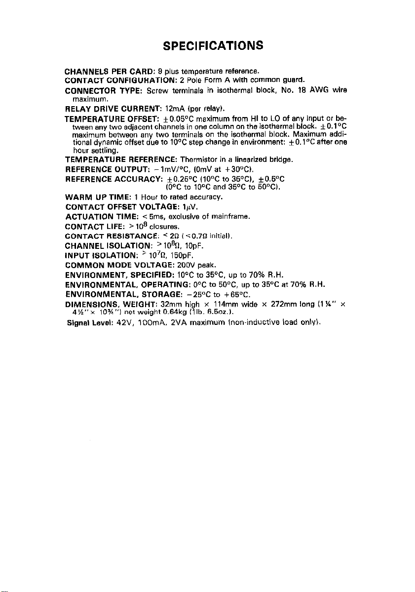
CHANNELS PER CARD: 9 plus temperature reference.
CONTACT CONFIGURATION: 2 Pole Form A with common guard.
CONNECTOR TYPE: Screw terminals in isothermal block, No. 18 AWG wire
maximum.
RELAY DRIVE CURRENT: 12mA lper relay).
TEMPERATURE OFFSET: i0.05°C maximum from HI to LO of any input or be-
tween any two adjacent channels in one column on the isothermal block. * O.lOC
maximum between an two ferminals on the isothermal block. Maximum addi-
tional dynamic offset J ue fo 10°C step chsngo in environment: *O.l°C after one
hour settling.
TEMPERATURE REFERENCE: Thermistor in a linearized bridge.
REFERENCE OUTPUT: - ,m”,°C, ,Om” at +3O”CI.
REFERENCE ACCURACY: f0.2S°C ,,O’=C to 35OC,, +0.5OC
WARM UP TIME: 1 Hour to rated accuracy.
CONTACT OFFSET VOLTAGE: I,,“.
ACTUATION TIME: < 5ms, exclusive of mainframe.
CONTACT LIFE: > lo* cbs”res.
CONTACT RESISTANCE: < 2n (<O.,O inidall.
C”ANNEL ISOLATION: ‘109O. 1OpF.
INPUT ISOLATION: a 10’R. 15OpF.
COMMON MODE VOLTAGE: 200” peak.
ENVIRONMENT, SPECIFIED: ,O’=C to 35°C. up to 70% R.H.
ENWRONMENTAL, OPERATING: O°C to 50°C, up to 35OC at 70% R.H.
ENVIRONMENTAL. STORAGE: -25OC to +55”C.
DIMENSIONS, WEIGHT: 32mm high x 114mm wide x 272mm long I1 %*’ x
4%“~ 10%“) net weight 0.54kg Illb. 5,502.).
Signaf Level: 42”. 1DDmA. 2VA maximum Inon-inductive load only).
,O”C to 10% and 35°C to 60°Cl.
Page 6
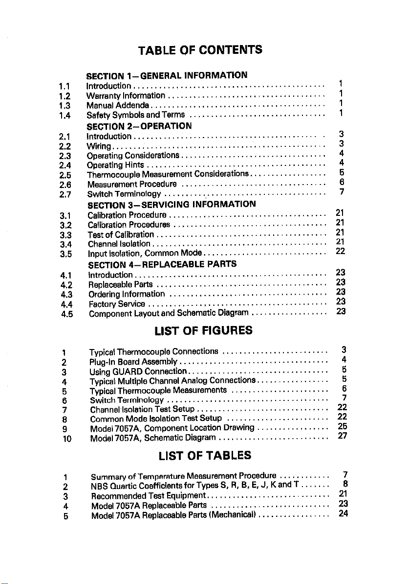
TABLE OF CONTENTS
SECTION l-GENERAL INFORMATION
Introduction
1.1
Warranty Information
1.2
ManualAddenda
1.3
Safety Symbols and Terms
1.4
SECTION Z-OPERATION
Introduction
Wiring
Operating Considerations,,
2.3
Operating Hints
2.4
Thermocouple Measurement Considerations,
2.5
Measurement Procedure
2.6
SwitchTerminology.. .....................................
2.7
SECTION 3-SERVICING INFORMATION
Calibration Procedure.,
3.1
Calibration Procedures
3.2
Test of Calibration
3.3
Channel Isolation,,
3.4
3.5
Input Isolation, Common Mode
SECTION 4-REPLACEABLE PARTS
introduction,
4.1
ReplaceableParts
4.2
Ordering Information
4.3
FactoryService ..........................................
4.4
4.5
Component Layout and Schematic Diagram
.............................................
.....................................
.........................................
................................
............................................
...................................................
................................
..........................................
..................................
...................................
....................................
........................................
.......................................
............................................
........................................
.....................................
LIST OF FIGURES
Typical Thermocouple Connections
:
Plug-In Board Assembly.
3
Using GUARD Connection
4
Typical Multiple Channel Analog Connections.
Typical Thermocouple Measurements
Switch Terminology
ii
Chsnnel~lsolation Test Setup
Common Mode Isolation Test Setup
;
Model 7057A. Component Location Drawing
9
Model 7057A. Schematic Diagram
10
..................................
.................................
.....................................
.................
.............................
..................
.........................
......................
..............................
.......................
.........................
...............
................
21
;1
21
22
23
ii
23
23
3
4
5
5
6
7
22
22
26
27
LIST OF TABLES
Summary of Temperature Measurement Procedure
:
NBS Quwtic Coefficients for Types S, R, B, E, J, K and T
Recommended Test Equipment.
3
4
Model 7057A Rep!aceab!e parts .:
5
Model 7057A Replaceable Parts ,Mec”a”~ca,, 24
...........................
.. : .,:
.... :
...........
................
7
......
2:
23
Page 7

SECTION 1
GENERAL INFORMATION
1.1 INTRODUCTION
The Model 7057A is a thermocouple scanner card which is field-installable in an
appropriate scanner mainframe (e.g. Model 7051. Since it combines the functions of a thermocouple scanner and uniform temperature reference, it is
especially useful for scanning thermocouples. The input terminals aie HI0 alloycopper set in an isothermal block to minimize temperature differences. A thermistor sensor within the isothermal block is used with a bridge network located
on the Model 7057A to give an indication of the temperature reference or cold
junction. The temperature of the heat sink is used to calculate the corrected
thermocouple output. The output voltages of each thermocouple must be converted to temperature PC or OF) using appropriate thermocouple tables or
polynomial equations. In addition any channel may be used for monitoring lowlevel signals. The Model 7057A uses Z-pole form A contacts for witching of
signals up to 35V peak or IOOmA peak. Input and output connections 818 made
through the rear panel of the scanner mainframe using #4 screw terminals on the
Model 7057A.
1.2 WARRANTY INFORMATION
Warranty information is stated on the inside front cover of the manual. If there is
a need for service, contact the Keithley representative or authorized repair facility
in your area. Check the back cover of this manual for addresses. The service
form supplied at the end of this manual should be used to provide the repair
facility with adequate information concerning any difficulty.
1.3 MANUAL ADDENDA
Any improvements or changes to this manual will be explained on an addendum
included with this manual.
1.4 SAFETY SYMBOLS AND TERMS
The symbol
i;;i;TbolN
The WARNING used in this manual explains dangers that could result in
personal injury or death.
The CAUTION used in this manual explains hazards that could damage the
instrument.
denotes that the user should refer to the operating instruc-
A
denotes that a high voltage may be present on the ter-
1
Page 8
SECTION 2
OPERATION
2.1 INTRODUCTION
This section provides information needed to use the Model 7057A with an
*ppropriate scanner mainframe.
2.2 WIRING AND INSTALLATION
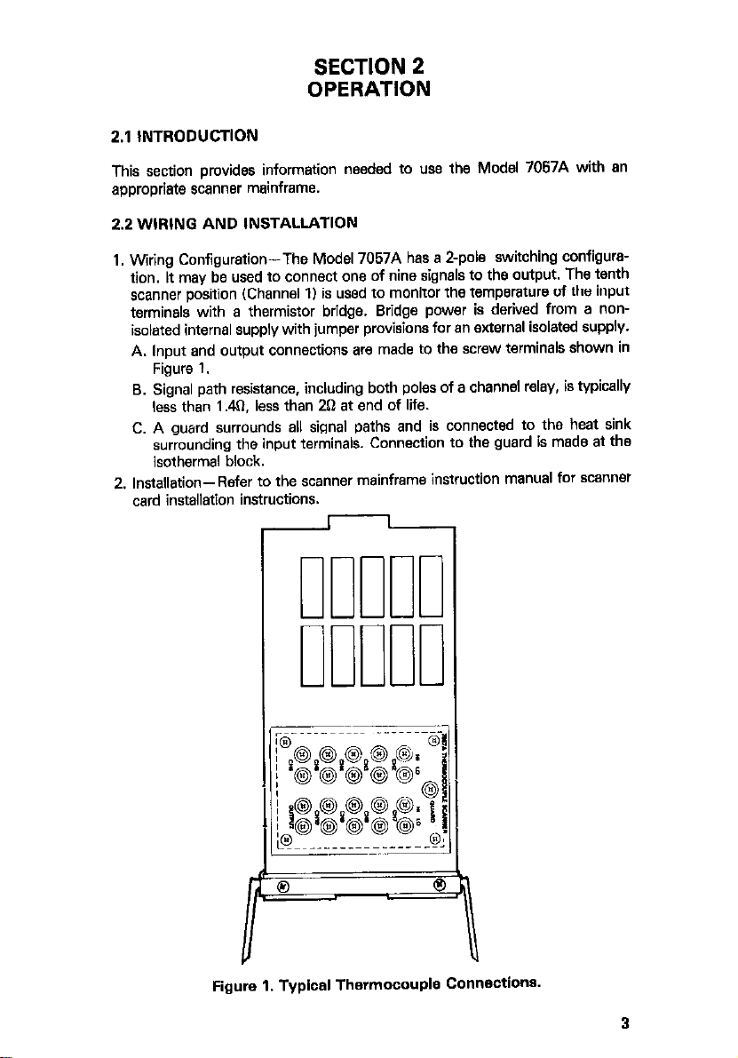
1. Wiring Configuration-The Model 7057A has a Z-pole switching configuration. It may be used to connect one of nine signals to the output. The tenth
scanner position (Channel 1) is used to monitor the temperature of the input
terminals with a thermistor bridge. Bridge power is derived from a non-
isolated internal supply with jumper provisions for an external isolated supply.
A. lnwt and output connections are made to the screw terminals shown in
Fi& 1.
8. Signal path resistance, including both poles of a channel relay, is typically
less than 1.4?, less than 2Q et end of life.
C. A guard surrounds 811 signal paths and is connected to the heat sink
surrounding the input terminals. Connection to the guard is made at the
isothermal block.
2. Installation-Refer to the scanner mainframe instruction manual for scanner
instructions.
I
I-==
Figure 1. Typical Thermocouple Connections.
3
Page 9
2.3 OPERATING CONSIDERATIONS
1. Signal Level-IOV peak, 1OmA peak with a resistive load for expected life.
Maximum peak instantaneous rating is 35V.
2. Contact Potential (Laboratory Environment)-Less than I$/ from input to
output when copper wires are used.
3. Isolation-Guarded interchannel resitanceis nominally@!?. Guarded cap*citance is less than 1OOpF between any two channels.
4. Maximum Levels-A 2OOV peak between channels or from channel to
guard or mainframe (digital) common.
5. Operating Environment-OQC-50°C, up to 35°C at 70% relative humidity.
2.4 OPERATING HINTS
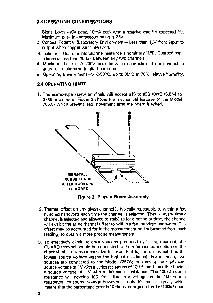
1. The clamp-type screw terminals will accept #I8 to #36 AWG (0.044 to
0.005 inch) wire. Figure 2 shows the mechanical features of the Model
7057A which prevent lead movement after the board is wired.
Figure 2. Plug-h Board Assembly
2. Thermal offset on any given channel is typically repeatable to within a few
hundred nanovolts each time the channel is selected. That is, every time a
channel is selected and allowed to stabilize for a period of time, the channel
will exhibit the same thermal offset to within a few hundred nanovolts. This
offset may be accounted for in the measurement and subtracted from each
reading, to obtain a more precise measurement.
3. To effectively eliminate error voltages produced by leakage current, the
GUARD terminal should be connected to the reference connection on the
channel which is most sensitive to error (that is, the one which has the
lowest source voltage versus the highest resistance). For instance. two
sources are connected to the Model 7057A; one having an equivalent
source voltage of IV with a series resistance of IOOkR and the other having
a source voltage of .lV with a lkn series resistance. The lOOka source
resistance will develop 100 times the error voltage as the lkn Knwze
resistance. Its source voltage however, is only 10 times as great. which
means that the percentage error is 10 times as large on the lV/lOOkn chan-
4
Page 10
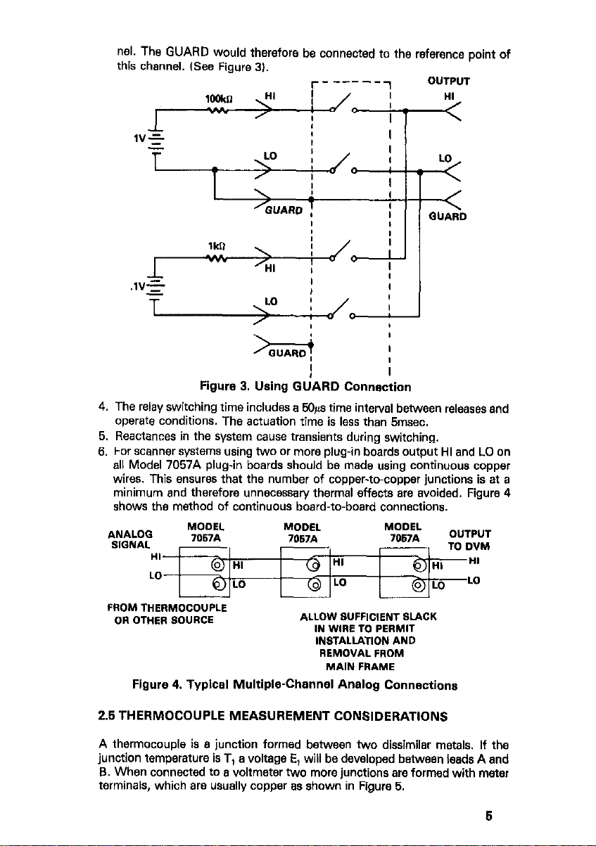
nel. The GUARD would therefore be connected to the reference point of
this channel. ISee Figure 3).
Figure 3. Using GUARD Connection
4. The relay switching time includes a 9&s time interval between releases end
operate conditions. The actuation time is less than 5msec.
5. Reactances in the system cause transients during switching.
6. For scanner systems using two or more plug-in boards output HI and LO on
all Model 7057A plug-in boards should be made using continuous copper
wires. This ensures that the number of copper-to-copper junctions is at a
minimum and therefore unnecessary thermal effects are avoided. Figure 4
shows the method of continuous board-to-board connections.
Figure 4. Typical Multiple-Channel Analog Connections
2.5 THERMOCOUPLE MEASUREMENT CONSIDERATIONS
A thermocouple is B junction formed between two dissimilar metals. If the
junction temperature is T, a voltage E, will be developed between leads A and
B. When connected to B voltmeter two more junctions are formed with meter
terminals, which are usually copper as shown in Figure 5.
Page 11

Figure 5. Typical Thermocouple Measurement
The voltage measured by the voltmeter is proponional to the difference between temperature T, and T2. To determine T,, T2 the thermoelectric properties of the thermocouple are needed. Data is available to determine the voltage
versus temperature relationship based on a reference temperature IT*) of 0°C.
Thus, if the thermocouple-to-copper junctions were maintained at O°C it
would be possible to determine T, directly by referring to thermocouple
reference tables*, which give temperature as a function of the meter reading
V,. If these junctions are different from 0°C a voltage E2 will be introduced,
where V, = E,-E,.
2.6 MEASUREMENT PROCEDURE
In the Model 7057A the reference temperatwre T is measured by a dual thermistor in a bridge circuit. The temperature of a thermocouple connected to
Channels 2 through 10 is determined by the following procedure:
1. Measure the voltage for the reference junction V and calculate Tz. T2 =
30-w, x 1031.
2. Determine the reference junction voltage, E2, either from thermocouple
reference tables’ or by the calculation**:
5 = a0 + A, T + a,p + aaT + a,,+ where T = T2 as determined in step 1
above. Q is expressed in microvolts. The constant a0 through a4 are a
function of the thermocouple type connected to the channel. The coeff-
CiWntS, aO, a,, a?, a3 and a4 are dependent on the thermocouple type and
temperature range under consideration.
3. Measure the thermocouple voltage V, at the channel output. Convert to
microvolts.
4. Add b to V, to determine E,. E, =V, +E, (where V, is expressed in
microvoltsl.
5. Determine the thermocouple temperature, T,, either from thermocouple
reference tables* or by calculation**:
TI = a, + %EI. + %E12r + e,E? + %EI+ (where E, is expressed in microvoltsl.
6. For example, consider a type J iron-constantan thermocouple at 300°C
(T,I. The reference junction temperature will be 6 to 10°C above ambient,
say 36% IT2).
A. The bridge output ichannel II will be -.006V. Since the bridge output is
zero when T, = 30°C this indicates T2 = 36OC.
B. Using NBS Monograph 125 to determine the reference voltage for a type
J thermocouple gives b 4 1649,O@V. Using the most accurate quark
approximation formula (Table 21 for this range gives lB49.085@,
C. The voltage at Channel 1, which is V,, will be 14476,OpV. IV, = E, -b).
D. Add 6 to V, and get E, = 16325.0@,
6
Page 12

E. Using Table A6.2.1 to find the thermocouple temperature gives
300.00°C. Using the formula (Table 2) gives 299.995°C.
* Thermocouple Reference Tables, Based on the IPTS-66 National Bureau
Standards Monograph 125. (SD Catalog No. C13.44~1251
** See also Table 2 which summarizes the quartic coefficients.
Table 1. Summary of Temperature Measurement Procedure
Quantity
channel output V,.
Determine equivalent
V2
bLSl
Tz = 30-I!!, x 103)
Measured desired
Calculate correction
VI
(volts)
F
lCalcuiat~~olt.age E,. )
Calculate equivalent
temperature TV.
2.7 SWITCH TERMINOLOGY
Throughout this manual the terminology Form A is used. The term Form A is
used in switch terminology and is described as follows:
1. Form A is simply a single pole normally open ISPNOI switch (refer to
Figure 6). A Z-pole switch normally open is classified as 2 Form A.
2. Form B is similar to Form A except that its contacts are normally closed
(refer to Figure 61. A Z-pole switch normally closed is classified as a 2 Form
B.
3. Form C is shown in Figure 6 as a single pole double throw switch. It could
also be a multipole switch such as a Z-pole which would be classified as a 2
-- 1 E, = E2 + V,.x-lO-” 1 mic~v,lts 1
T, = a, + a,E, + a,P, +
*Pl + Wl
T, IW
Figure 6. Switch Terminology
7
Page 13

Reference Junction
1
16% to 176%
Correction
” tn m
Table 2. NBS Quartic Coefficients for Types S. R. B. E. J. K. and T.
Argument hp.
a0
=I
=2
Argument EXP. Arg”me”t Exp. Arg”ment EXP.
5.5439639
5.9791m
6.2516%!3
6.5554!232
Ma34421
8.7228147
9.5827994
9.4531354
2.9873073
3.4129348
6.4091373
3.9952876
*.co4320*
1.3532278
5.3994446 +o 1
I.2467754 -2
a3
Argument Exp.
a4
Exact-Approx.
Error
Range ILNV)
Page 14

c
4.1137317 +1
4.4507790 +1
4.1670535 + 1
-3.0938374 +1
z!2zm7 +7
1.3866867 +2
1.3923740 +2
4.6133695 +3
2.3131446 +4
I
-2.0241757 -5 -2.0241757 -5
-m349c6, -5 -m349c6, -5
-9.cl763455 -6 -9.cl763455 -6
-7.0073775 -6 -7.0073775 -6
-6.319500, -6 -6.319500, -6
-1.8612979 -6 -1.8612979 -6
-,.33496,, -6 -,.33496,, -6
- I .6,62,80 - I .6,62,80 - 6 - 6
-4.9,94442 -6 -4.9,94442 -6
-3.2873314 -6 -3.2873314 -6
4.659nc8 -8 4.659nc8 -8
7.7266682 -8 7.7266682 -8
1.032002 -4 1.032002 -4
4.934,196 -4 4.934,196 -4
Page 15

4rgumem Exp.
80
Zrgumenf Ex*.
a1
-4.0674108 +*
-5.mm84 +*
-5.4505828 +*
1.6618169 +3
1.5132838 +3
2.4m3703 +3
1.5787334 +3
-7.1904948 +4
8.8532076 14
5.4295008 +o
5.7622558 +o
6.1429772 +!I
6.4615269 +o
6.596212u +o
8.7490234 +o
9.673111, +o
9.5942872 +o
2.3048626 +O
*.795%247 +o
4.1604579 -1
*.6321,44 +o
1.94423a3 +*
- ,.5014129 +*
1.1446885 -2
9.2715271 -3
7.1515857 -3
5.7010917 -3
5.1559203 -3
1.7115155 -3
-2.6994046 -4
-1.2813352 -4
8.7635426 -3
8.1571403 -3
1.0549178 -2
8.31co314 -3
- 1.7913090 - 1
9.5376167 -2
-1.1295306 -5
-7.1346883 -6
-3.7639447 -6
-1.8683292 -6
-1.2385309 -6
7.5039035 -7
2.5536988 -6
2.4468512 -6
-2.3016?318 -6
-1.9701159 -6
-3.0383621 -6
-2.0332036 -6
7.9264764 -6
-1.6644901 -5
-0.01 to +o.o,
5.w2w96 -9
2.5877454 -9
9.6963832 -10
2.3636365 -10
1.m3.27643 -11 1.m3.27643 -11
-3.oo96280 -10 -3.oo96280 -10
-8.9155191
-8.915549,
-8.6286758 -10
7.4284923 -11
6.5568964 -12
1.8540516 -10
1.6260416 -11
- 1.3167245 -8
-8.3062870 - 10 -8.3062870 - 10
- 10
- 10
-7 to 16
- 16 to 12
-35to25
-551036
7
-661036
- .4 to .5
-1~7 to 1.6
-2.1 to 1.8
- .05 to .05
- .05 to .05
- 45 to .05
- .05 to .05
-1.0 to 1.3
.05 to .05
Page 16

,rg"ment Exp.
=0
Argument Exp.
a2
Argument Exp.
84
4.5509556 +1
4.9160016 +1
4.8343651 +1
-4.1134469 10
3.7487318 +1
8.0559850 +1
1.4180146 +3
3.176!3333 +3
1.2683437 +4
1.6251434 -1
1.5239494 -1
1.4441607 -1
1.3344190 -1
1.3752efj? -1
1.12ed875 -1
1.1054689 -1
1.1098270 -1
1.2738464 -1
1.1515zc4 -1
1.0442877 -1
9.0181346 -2
-5.m2431 -1
- 2.6747958 + 0
-2.0454379 -5
-1.3755675 -5
-9.5014952 -6
-7.4485484 -6
-6.7661171 -6
-2.86ces78 -6
-2.3559046 -6
-2.4353s9o -6
-4.3132296 -6
-2.9827002 -6
-1.9Enm -6
-7.4069329 -7
5.6190639 -5
2.2334214 -4
2.5404935 -9
1.2610922 -9
6.2073358 -10
3.8266182 -10
3.M2c473 -10
8.6173702 - 11
3.9276246 -11
-1.1767904 -13
-4.4281251 - 14
-1.9622497 -14
-7.4617277 -15
-5.4254672 -15
-1.1440038 -15
3.33-4 -16
1.8172612 -16
-1Ea3798 -15
-3.78Gss57 -16
2.4513433 -16
9.4290495 -16
3.0369250 -14
1.0882779 -13
-13to3
-4to7
-6 to 10
-7to13
-7 to 14
-.0tto.o4
-.08tom
-.lOfO .12
- .m* to .x3*
-.Oll to ,011
-.x05 to .wo5
.wo5 to .ooo5
-.ll to .I8
.ccm to .a307
Page 17

a0
4rg”ment EXP.
=I =*
PIrgument EXp. Argument Exp.
Argument Exp.
a3
1.3740347 +1
-2.5321108 +1
-1.1708354 +*
-9.8446269 +2
1.3702395 + 3
~4.76445Sl +*
- 6.4mas29
‘Quadratic. cubic. and quark approximations f
E=ag+alT+a*T*+a3T3+aqT4where E is in
+ 2
- I.3749133
-3.2914888
-9.9736579
3.smx94
3.367OEsS
~f!Eiy~~
7e dafa as a function Of temperat”le ,Y
:rwolfs and T is in degrees Celsius.
- 1 6.3446673
-1 5.9766638
-2 5.4976533
-1 4.5539656
+o 8.2282215
-3
-3
-3
-3
-4
-5.6339756 -7
-5.9983692 -7 -9.7c41131 -11 -.,*to.*o
- 5.7165679 7
~3.3057S24 -7 -2.w18428 10
-9.1094186 -8 -2.8098361 -10
-8.0141311 -7 - 2.7203972 - 1, - .05 fO .05
-3.6623964 -7 -3.6S6Slcc -10 -2.0 fo 1.8
3.6623964 -7 -3.69691cc -10 -2.010 1.8
*.‘lm1224 -6
3.W5686 -6 -9.4548852 -10 .05 fO .05
2.2417410 -6 ~7.6471224 10
2.4305578 -6 -8.1518033 -10 - .05 to .05
-1.2267180 -6
1 selecied temperat”re ranges. me expansion is 0‘ the form
-1.1808558 -10 -22f0.14
-1.0818193 -10 -.,m,.o
-4to5
-*to9
-7.7901142 -10 .05 ro .05
- $5 fO .05
0.01 fO +o.o,
Page 18

80
E,,W
Range
WV1
EX*Ct-App,OX.
,rgument Ex
-5.7447033 -4
7.2874oE6 -1
5.7822214 -1
4.SS2Slrn -1
1.8946288 4
2.0949015 4
2.2394664 i
3.2188156 4
3.44,5x4 t
4.6255054 -1
3.ux.6136 -1
2.7222162 -1
2.4988761 -1
1.8282378 -1
1.7031473 - 1
1.5828913 -1
1.4979551 - 1
-3.177193, -4
-1.6039309 -4
-1.0349686 -4
-8.2176262 -5
-6.81oo680 -5
~3.6330332 -5
-2.71@33,2 -5
-1.1561743 -5
-8.9696912 -6
-7.0050689 -6
~6.n762S3 -6
-301075
-35row
-45 to 110
-5otom
-50 TO 130
-.09fO,.O
-3to3
-5to5
-.cmro.o03
-.0*5 to .o*o
- .W, 10 .w,
- ,031 to .Wl
1
n is Of the form
Page 19

*0
Argwnent Exp.
*3 *3
\rgument hp. \rgument hp.
aq
*rgument Exp.
‘Cluadr*tic, cubic. and qu ‘Cluadr*tic, cubic. and qu
E=ar,+a,T+a*T2+,3T: E=ar,+a,T+a*T2+,3T:
-8.5384268 +2
-1.383%33 +3
-5.1503130 +4
5.9287179 +1 5.9287179 +1 7.0983783 -2
5.6754764 +1 5.6754764 +1 5.7443085 -2
5.8943714 +1 5.8943714 +1 5.611850, -5
5.8318736 +1 5.8318736 +1 5.4292960 -2
5.m7691 +1 5.m7691 +1 5.3761106 -2
5.8734537 +1 5.8734537 +1
6.5022W +1 6.5022W +1
6.7*111*6 fl 6.7*111*6 fl 3.1669230 -2
-1.6691278 +2 -1.6691278 +2 4.1877018 -1
5.8637565 +1 p4.67*w25 -2
5.0763!?31 -2
3.4354900 -2
5.*421&u -5 5.*421&u -5
-5.GmmTn2 -5 -5.GmmTn2 -5
-5.9506584 -5 -5.9506584 -5
-5.6286941 -5 -5.6286941 -5
-5.2870696 -5 -5.2870696 -5
-4.7621793 -5 -4.7621793 -5
-2.9763494 -5 -2.9763494 -5
-2.9237913 -5 -2.9237913 -5
-3.1228607 -4 -3.1228607 -4
-1.443202 -6
3.8137875 -7
1.3960921 -7
2.2327737 -8
2.0825828 -8
1.5352840 -8
1.465!3118 -8
7.w39401 -9
8.1514671 -9
8.5283044 -8
-5to5
- .5 to .4
-6oto3n
-8704
-3ro4
-,8tol7
-2 to 2.5
- .03 to .03
-.06to.oE
- .12 70 + .24
Page 20

Page 21

I. Ouartic Equation
Error
Range
WV)
-2COt00
-mto76o
-MO to 12cm
-2oto5W
0 20 4cQ
oto780
0t01200
4ooto760
4ooto12w
sooto760
780 to ,209
Reference Junction
Correction
0 to 50
t
-5.7831co5 +3
,.,,2,3,, +3
-2.5724435 +4
3.9264982 +4
5.04cm743 +1
4.8xQ533 + 1
4.,052807 + 1
5.m +,
5.0452399 +1
5.12E8213 +1
5.5881877 +1
9.77l8!35 +1
,.8%9x, +,
2.2151898 +2
-1.47850,7 +2
5.0373743 +1
a2
PIrgument hp.
3.Mo906) -2
3.269em2 -2
2.552650 -2
2.ax2596 -2
2.840913, -2
2.oo40854 -2
1.4207854 -2
-1.18E843n -1
5.3882730 -2
-4.041808, -1
3.647092, -1
3.01670,, -2
a3
Fwgumant 5xp.
-8.3493983 -5
-6.993603, -5
-2.2xl82s5 -5
-8.E&883o5 -5
-8.7558436 -5
-4.~ -5
3.1325181 -5
1.3184454 -4
-2.2171472 -5
4.2749984 -4
~2.7029305 -4
-7.4293513 -5
2.5174022 -7
5.,,,2,2!3 -8
7.1373907 -8
5.3587105 -8
5.ez8zo4a -8
3.281s4wJ -8
-1.5023,,0 -8
-4.8218788 -8
1.8445398 -10
1.6174242 -7
7.2113090 -8
Page 22

a2
4rgument EXP.
a3
Argument Exp.
I 0 0 fO to ,200 400
Wuadratic. cubic. and q~artic approximation*
T=aO+alE+a2E2+a3E3+aqE4where E is in r
0t0760
4OOt07M1
403 fO ,203
6Wt07M1
700 to 1200
!3.2808351 +1
-1.1075293 +2
1.8020713 +2
-6.3828680 +2
1.8843850 -2
2.1155170 -2
2.1676850 -2
1.8745056 -2
1.8750953 -2
1.9323799 -2
1.8134974 -2
5.4483817 -3
2.8651303 -2
-4.5284199 -3
7.4068745 -2
- 3.3513149 -7
-2.1844454 -7
~1.8094256 -7
~I.8512600 -7
-1.03ca20 -7
1.2443!397 -11
3.9094347 -12
7.8771919 - 12
8.3681958 -12
3.7084018 -12
~2.5849263 -14
-1.5227150 -16
- 2.4303017
-1.1897222 -18
-1.328n568 -18
-5.1031937 -17
2.1141718 -17
9.9364476 - 17
-4.9012035 - 18
1.5521511 -18
- 17
Page 23

IAlgUmenf
a2
Argument EXP.
83
Argm-“ant Exp.
1.3223524 +3
-3.6456236 +1
2.1326066 +3
-9.0373649 +2
-2.5972816 +3
3.9676618 +l
3.6478446 fl
3.6762217 +l
4.09B640 * 1
4.0961103 +1
3.9443859 +1
3.0191663 fl
3.8349319 +1
2.5608012 +1
4.0577145 +1
5.M75276 +1
3.1063356 -2
2.8266412 -2
2.4514587 -2
-3.2619221 -3
-1.5!%2510 -4
5.aJ53822 -3
2.76m912 -2
9.9993329 -3
3.7091744 -2
9.5092149 -3
- 1.4576419 -2
-9.16m895 -5
-1.14a8433 -4
-4.3@319%3 -5
S.FJl4137 -6
- 1.252RW.J - 5
-4.2015137 -6
-2.4734437 -5
-8.744446 -6
-3.3517324 -5
-1.0989249 -6
9.4854151 -6
3.0X+3626 -8
-2.8153447 -8
2.5127588 -8
-1.6912373 -9
3.2764725 - 8
I.3317059 -10
6.9798332 -9
1.7108618 -9
9.9607405 -9
-3.0753213 -9
-3.1,x779 -9
-1.1 fO 1.2
-.@3to.o+
-1mtom
-'25 to 45
-25to20
-60 to 110
-.9to1.4
-,2to,,
- .05 fO .o,
- .05 to .I3
- .05 to .05
-.ffito +.14
1 is of the form
Page 24

a0
Argument EXP.
-r
a7
,rgu”lent Exp.
a2
Argument Exp.
a3
Argument EXP.
a4
*rgument Exp.
-270too
-200030
-2ootot?lm
-20t05CC
0 to ml
-2.4707112 t,
6.2300671 TO
-3.w30992 + 1
-3.1617495 CO
2.3615582 +2
1.2329875 -2
2.3763697 -2
2.8346886 -2
2.4363851 -2
2.4383246 -2
2.5132785 -2
2.3465633 -2
2.4655374 -2
3.1425797 -2
2.7115517 -2
1.1066277 -3
-1.4434305 -5
-2.4382217 -6
-5.8008526 -7
5.6206931 -8
9.7830251 - 9
-6.0883423 -8
-3.1332620 -7
-7.8788333 -8
-4.0935633 -7
-2.1941595 -7
8.2516607 -7
4.2824666
6.8203073
2.5720615 11
-3.8825620 -12
3.6276665 -12
5.5358209 -13
6.5075717 - 12
1.3266743 12
8.5462602 -12
4.6762626 - 12
-1.3558849 -11
9
4.2028679 - 13
10
-9.4854031 -14
-3.6813679 -16
3.9120208 17
-2.5756-W -16
9.3720918 18
-3.9663834 -17
1.5580541 -18
-5.5696636 -17
-2.9316611 -17
9.1638500 -17
Page 25

I. Quartie Equafion
Argument
Exp.
3.9439319
+1
-27OtoO
-2cntoo
~200104m
Reference Junction
0 to 403
Correction
0 20 50
ä
3.8749356 +1
3.8621703 i-1
3.64@407 +1
3.8ml239 +1
=,
Argument Exp.
6.2407452 -2
4.5149603 -2
4.5433050 -2
4.6651731 -2
4.1277w -2
=*
-4.7753448 -5
8.0773568 -5
irgument Exp.
2.6846647 -7
-2.5773959 -8
1.4661300 -8
1.5999833 -8
=4
-0.04to t0.081
-9107
- .14 to .I3
-7 to 3.5
-9 to .9
I
Argument
4.3553379 -3
2.3837090 -2
2.6792411 -2
2.5661297~ -2
“Ouadratic. cubic. and qualfic approximarions fo fix data as a tuncti
T = a0 + al E + a2E2 + a3E3 + a4E4 where E is in mi~rovolts and T is in degrees Celsius
Argument EXP.
-2.0325426 -5 -5.4720813 -9
-2.9876839 -6
- 1.0370271 - 6 6.1330327 11
-6.195469 -7 2.2181644 - 11
=2
Argument Exp.
-7.1945810 10
=3
-5.0865527 13
-1.cc41943 -13
-1.39e8335 -15
~3.5500900 -16
I
Page 26

SECTION 3
SERVICING INFORMATION
3.1 RECOMMENDED TEST EQUIPMENT
The recommended test equipment for calibration and performance verification
is given in Table 3. Test equipment other than recommended may be
substituted if specifications at least equal those given in Table 3.
Table 3. Recommended Test Equipment
Itam Description
A 1 DMM
6 Voltage source
C Electrometer
D Scanner Mainframe
3.2 CALIBRATION PROCEDURES
To calibrate the Model 7057A do the following procedure:
1. Remove the green wire on the Model 7057A.
2. Connect DMM across R104 l6.151kQ resistor).
3. Adjust RIO1 for 175.92mV fO.lmV.
4. Remove DMM and reconnect the green wire.
3.3 TEST OF CALIBRATION
Using RFL industries oil bath lor equivalentl, submerge thermistor Ion 7057Al
with temperature standard measuring device (Thermometrics S-10 probe or
equivalent) into the oil. Allow to stabilize and note the difference lat 30°C).
The difference should be less than .2’C.
3.4 CHANNEL ISOLATION
A. This test ~measures the leakage resistance between two channels on the
board. One channel is to be open and the other closed. Set up the test circuit shown in Figure 7.
B. Short the HI and LO connections of each channel on the Model 7057A. Do
not connect the channels together, just short the HI and LO terminals.
C. Set the Model 705 to the Channel mode, Channel 2 and the Step mode.
Set the electrometer to Amps and program the Model 230 to output 1OOV.
Take the electrometer out of ZERO CHECK. Program the channel under
test as open and other channels as closed.
D.Take the reading on the electrometer. The reading should be less than
1 x lo-6A. Using Ohm’s Law calculate the channel isolation. For example:
R = E/I = IOOVll x lo-CA = 1 x lO%?. Due to the capacitance of the circuit, the offset current may be high until the capacitance of the circuit is
charged up. Wait until the readings settle out.
E. Manually scan through channels 2 through 10 repeating step C and D for
each channel.
Channel 1 is the temperature reference channel.
Specifications
I 1OuV resolution
1oov DC
IpA resolution
-
NOTE
21
Page 27

Figure 7. Channel Isolation Test Sat Up
3.5 INPUT ISOLATION, COMMON MODE
A. This test measures the leakage resistance between signal lines and power
line ground. Set up the test circuit shown in Figure 8.
El. Short the input HI and LO terminals of each channel with a short piece of
solid copper wire. Do not connect the channels together, just short the HI
and LO terminals.
C. Insert the Model 7057A into the mainframe and sea the Model 705 to the
Channel mode, Channel 2 and the Step mode.
D. Set the electrometer to Amps and program the Model 230 to output 1OOV.
Take the electrometer out of ZERO CHECK.
E. Take the reading on the electrometer. The reading should be less than
1 x lo-“A. Using Ohm’s Law calculate the isolation ileakaae resistance).
For example: R-=E/I = lOOVl1 x 10m5A = ~lO’n.- Due to the
capacitance of the circuit, the offset current may be high until the
capacitance is charged up. Wait until the readings settle out.
F. Manually scan Channels 2 through 10 repeating step D and E for each
channel.
22
Figure 8. Common Mode Isolation Test Setup
Page 28

SECTION 4
REPLACEABLE PARTS
4.1 INTRODUCTION
This section contains replacement parts information, B schematic diagram
and component layout for the Model 7057A.
4.2 REPLACEABLE PARTS
Parts are listed alpha-numerically in order of their circuit designation. Table 4
contains parts list information for the Model 7057A. Table 5 contains a
mechanical parts list for the Model 7057A.
4.3 ORDERING INFORMATION
To place an order, or to obtain information concerning replacement parts,
contact your Keithley representative of the factory. See the inside front
cover for addresses. When ordering include the following information:
1. Instrument Model Number
2. Instrument Serial Number
3. Part Description
4. Circuit Description (if applicable)
5. Keithley Part Number
4.4 FACTORY SERVICE
If the instrument is to be returned to the factory for service, please complete
the service form which follows this section and return it with the instrument.
4.5 COMPONENT LAYOUT AND SCHEMATIC DIAGRAM
The component layout for the Model 7057A is shown in Figure 9, while
Figure 10 contains the Model 7057A schematic diagram.
Table 4. Modal 705JA Replaceable Parts
23
Page 29

CkCUl
t
Deslg.
Cl01
c102Cl11
KlOl
K102
K103
K104
K105
K106
ix
K109
KllO
RlOl
R102
R103
R104
R105
R106
R107R116
RTlOl
UlOl
Table 4. Model 7057A Replaceable Parts
Description
Capacitor, .l@, 5OOV, Polystyrene
Capacitor, lOpF, 25V, Alummm
Electrolytic
Relay, i Pole Form A
Relay, 2 Pole Form A
Relay, 2 Pole Form A
Relav. 2 Pole Form A
R&i; 2 Pole Form A
Relay, 2 Pole Form A
Relay, 2 Pole Form A
Relay, 2 Pole Form A
Relay, 2 Pole Form A
R&v. 2 Pole Form A
rot,‘ioon
Resistor, 77.77k, 0.02%, %W,
Wirewound
Resistor, 953.4n, O.OZ%, ‘/aW,
Wirewound
Resistor, 6.15kQ 0.02%, XW,
Wirewound
Resistor, 46.590, 0.02%, XW,
Wirewound
Resistor, 12k0, .l%, ‘/,W, Metal
Resistor, 27OQ, 5%, ‘law,
Composition
Thermistor
Low Drift Voltage Reference, AD5803
Film
Ksithley
Part No.
C-238-.1
c-314-10
RL-77
RL-77
E;
RL-77
RL-77
;::g
RL-77
RL-77
Rl-97-100
R-260-77.77k
R-260-953.4
R-260-6.151k
R-260-46.59
R-168-12k
R-76-270
RT-4
IC-151
Table 5. Model 7057A Replaceable Parts Mechanical
Description
Isothermal Block
Isothermal Block. Cover
Clamp Assembl;, Upper
a. Clamp, Upper
b. Strip, Rubber
Clamp Assembly, Lower
a. Clamp Cable, Lower
b. Stiip, Rubber
Handle (2 required)
Rivet (2 required)
Standoff (21 required)
#6-32 x 5116 Phillips Pan Head Screw
(2 required)
X6-32 x 1 inch Phillips Pan Head Screw
(2 required)
#6-32 x ‘X Phillips Pan Head Screw (Heat Sink)
(4 required)
#6-32 x J/4 Phillips Pan Head Screw (Heat Sink
Cover) (4 required)
#6-32 x 318 Phillips Pan Head Screw
Psrt Number
7057A-303
7057A-305
7055-303-06
7055-305
26621
7055-308
7055-307
26621
FA-119
FA-121
ST-139-7
Page 30

Figure 9. Model 7057A Component Location Diagram
26
Page 31

0
Y
Y
0
”
m
3
I;
a
Page 32

Page 33

 Loading...