

Tektronix 701 User manual
‘INSTRUCTION MANUAL
MODEL 701
ELECTRONIC RELAY
KEITHLEY INSTRUMENTS, INC.
CLEVELAND, OHIO
i ‘.
WARRANTY .
We warrant each of our product6 to be free from defects in material
and workmanship.
Our obligation under this warranty is to repair or
replace any instrument or part thereof, except tubes, transistors,
fuses, and batteries, which, within a year after shipmqt to the
original buyer, proves defective on examination.
DAMAGE IN SHIF'MENT
Be sure to include the instrument mods1 number and serial number in
all conmnulications.
If the instrument is damaged when received, or
fails to operate properly, a claim should be filed with the carrier.
Upon receipt of the claim agent's report, we will inform you regard-
ing repair or replacement.
BEPAIRS
When returning an instrument for repair or recalibration, it should
be securely packed against shipping damage and sent to the factory,
freight prepaid.
A brief letter describing the difficulty should
accompany the instrument.

CONTENTS
.
SECTION
INTRODUCTION . . . . . . . . , , . . , . . . . . . .
SPECIFICATIONS . . . . .' . . . . . . . . . . . . . <
DESCRIPTION . . . . . . . . . . . . . . . . . . . .
OPERATIONS..... . . . . . . . . . . . a....
MAINTENANCE .., . . ., . . . . ..a
. . ( . . .
Schematic Diagram
Voltage and. Resistance Chart
Replaceable Parts List
I
II
III
Iv
V
(.“..
SECTION I -
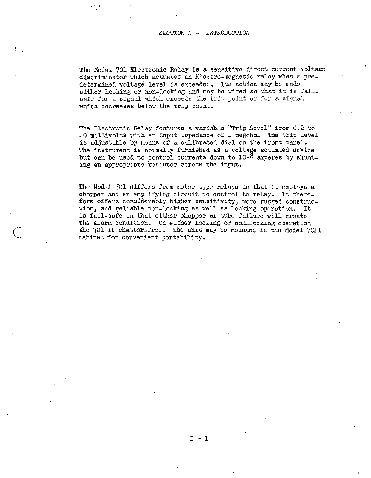
The Model 701 Electronic Relay is a sensitive direct current voltage
discriminator which actuates an Electra-magnetic relay when a predetermined voltage level is exceeded, Its action may be made
either locking or non-locking and may be wired so that it is fail-
safe for a signal which exceeds the trip point or for a signal
which decreases below the trip point,
The Electronic Relay features a variable "Trip Level" from 0.2 to
10 millivolts with an input,impedence of 1 megohm. The trip level
is adjustable by means of a calibrated dial on the front panel.
The instrument is normally furnished as a volts. e 8 actuated device
but can be used to control currents down to lo- amperes by shunt-
ing sn appropriate resistor across the input.
The Model 701 differs from meter type relays in that it employs a
chopper and an amplifying circuit to control to relay. It thersfore offers considerably higher sensitivity, more rugged construc-
tion, and reliable non-locking aa well'as locking operation, It
is fail-safe in that either chopper or tube failure will create
the alarm condition.
the 701 is chatter-free. The unit
cabinet for convenient portability.
On either locking or non-locking opsration
INTRODUCTION
may
be mounted in the Model 7011
,

i :
SECTION II
- SPECIPICATIONS
Sensitivity:
Input Resistance:
Differential between operate and release:
0.2 to 10 millivolts
1 megohm
200 microvolts
maximum
Permissible overload:
@solute zero stability:
.Repeatibility and Accuracy of trip point:
greater than 100 times
100
microvolts
2% of full scale
output : DPDT Relay 5 amps, 110 volts, non-inductive
wof Response: As shown in figure 1. Speed depends on
the degree to which the trip point is exceeded. Roclosure
times are approximately trip
Voltage Reference:
1 RM 12-R mercury battery. The battery
times.
life is in excess of 30,000 hours.
Tube Complement:
l-ES%, l-X%X7, l-2D21
Chopper: James
Dimensions:
a stand~relay rack.
TRIP TIME
IN
MIUISECONDS
25
cl281
3" wide, 8" high, 134 deep. Will mount five in
'_
--.
I 1 I
I
.20 30 40 50 60
10
70 80
II7 171
I
yo loo
Percent Over Trip
II - 1
 Loading...