

Page 1

INSTRUCTION MANUAL
MODEL 660
GUARDED DC
DIFFERENTIAL
VOLTMETER
Page 2

WARRANTY
We warrant each of our products to be free
from defects in material and workmanship. Our
obligation under this warranty is to repair or
replace any instrument or part thereof (except
tubes and batteries) which, within a year after
shipment, proves defective upon examination.
To exercise this warranty, contact your Keithley
field engineering representative. You will be
given assistance and shipping instructions.
REPAIRS AND RECALIBRATION
Keithley Instruments and its internat.ional dis-
tributors maintain complete repair facilities.
To insure prompt repair or recalibration service,
please contact your Keithley field representative
before returning the instrument.
Estimates for repairs, normal recalibrations, and
calibrations traceable to the National Bureau of
Standards are available upon request.
Page 3

MODEL 660 DIFFERERTIAL VOLTMETER
TABLE OF CONTENTS
CONTENTS
Section
GENERAL DESCRIPTION. . . . .
1.
l-l.
Description. . . . . .
1-2. Operating Modes. . . .
l-3.
Applications . . . . .
1-4. Accessories. . . . . .
l-5. Specifications . . . .
l-6.
Equipment Shipped. . .
2. OPERATION. . . . . . . . . .
2-l. Front Panel Controls
and Terminals . . . .
2-2. Rear Controls and
Terminals . . . . . ,
2-3.
Preliminary Procedures
2-4. Operating Procedures .
2-5.
Model 6601A High
Voltage Divider . . .
2-6.
Recorder Output. . . .
2-7. Measuring Resistances.
2-8. Effects Due to Kelvin-
Varley Divider Gut-
put Resistance. . . .
2-9. loading and Off-Null
Resistance. . . . . .
2-10. Thermal EMF Precau-
tions . . . . . . . .
2-11. AC Effects on Measure-
ment. . . . . . . . .
2-12. Rack Mounting. . . . .
2-13. Placing in Rack. , . .
2-14. 234-Volt Operation . .
Page
1
5
5
5
5
6
8
8
LO
11
12
12
12
12
14
14
Section
Page
3-3. Kelvin-Varley Divider. . 16
3-4. Null Detector. . . . . . 16
3-5. Guarding . . . . . . . . 17
4. MAINTENANCE. . . . . . . . . . 19
4-l.
General......... 19
4-2. Parts Replacement. . . . 19
4-3. Troubleshooting. . . . . 19
4-4. Adjustment of
km
Balancing Controls. . . 22
4-5. Zener Current Test . . . 23
4-6. Calibration Procedures , 24
4-7. Kelvin-Varley Divider
Verification. . . . . . 24
4-8. Range Calibration. . . . 25
4-9. Reference Voltage Sup-
ply Stability Test. . . 29
REPLACEABLE PARTS. . . . . . . 37
5.
5-1. Replaceable Parts List . 37
5-2.
How to Order Parts . . . 37
Model 660 Replaceable
Parts List. . . . . . . 38
Model 6601A Replaceable
Parts List. . . . . . . 44
Model 660 Schematic
Diagram 15199B. . . . . 47
Model 6601A Schematic
Diagram 16321B. . . . . 48
* Change Notice
3. CIRCDIT DESCRIPTION. . . . .
3-l. General, . . . . . . .
3-2. Reference Voltage
Supply. . . . . . . .
0664R
15
15
15
Wellow Change Notice sheet is in-
cluded only for instrument modifications affecting the Instruction Manual.
i
Page 4

GENERAL DESCRIPTION
MODRL 660 DIFFERENTIAL VOLTMETER
.
FIGURE 1.
ii
Keithley Instruments Model 660 Guarded DC Differential Voltmeter.
0564R
Page 5

MODEL 660 DIFFERENTIAL VOLTMETER
GENERAL DESCRIPTION
SECTION 1.
l-l. DESCRIPTION.
The Keithley Model 660 Guarded DC Differential Voltmeter is a convenient,
8.
self-contained potentiometric system that accurately measures dc voltages. It
has 20.02% limit of error from 100 millivolts to 500 volts full scale, 0.005%
repeatability, and a reference supply stable to 0.005% indefinitely without
manual standardization.
resolution is within 2 microvolts.
Features for convenient use include:
b.
automatically lighted decimal points;
input polarity switch; floating operation up to 500 volts off ground; fast
overload recovery; better than 45 decibels of 60-cps rejection.
l-2. OPERATING MODES.
a conventional vacuum tube voltmeter. As a potentiometer, it can measure
from 100 millivolts to 500 volts full scale with 20.02% limit of error and
from 100 microvolts to 100 millivolts full scale within 20 microvolts. As
a VTVM, the Model 660 can measure from 100 microvolts to 500 volts full
scale with an accuracy of *3% of full scale.
tances from 10 megohms to 50,000 megohms within *5%.
Maximum null sensitivity is 2100 microvolt6 full scale;
The Model 660 can be used as a potentiometer or as
GENERAL DESCRIPTION
five in-line readout dials with
10 to 25-millivolt recorder output;
It can also measure resis-
l-3. APPLICATIONS.
The Model 660 is used for measurements over a wide range. Typical ap-
a.
plications in the microvolt region are the matching of semi-conductors and
the monitoring of noise, transients and drift.
tions include power supply and meter calibration, and tube potential measure-
ments.
Overall stability of 0.01% indefinitely makes the Model 660 useful in
b.
measurements of extended duration.
stability, long-term drift runs, and monitoring during environmental and
reliability tests are possible uses.
The null-detector output permits use with potentiometric recorders and
c.
digital voltmeters equipped with automatic print-out. The Model 660 is useful in quality control, product development, inspection and production.
Floating operation to 500 volts is provided for measurements such as
d.
plate potential differences of balanced amplifiers.
l-4.
range of the Model 660 to 5000 volts.
its input resistance is 10 megohms. The overall limit of error of the Model
660 with the Model 6601A is 20.03%.
for the Divider,
ACCESSORIES.
a. Model 6601A High Voltage Divider is a 1OO:l divider which extends the
Measurements of long-term power supply
The divider accuracy is tO.Ol% and
Paragraph 2-5 gives operating instructions
High level voltage applica-
0664R
Page 6

GENERAL DESCRIPTION
Model 4000 Rack Mounting Kit, containing two brackets and a top cover,
b.
adapts the Model 660 for standard 19-inch rack mounting.
the Model 660 is 19 inches wide x 13-l/2 inches deep x 5 inches high.
to paragraph 2-12 for installing instructions.
l-5. SPECIFICATIONS.
AS AN ULTRA-STABLE POTENTIOMETER:
MODEL 660 DIFFERENTIAL VOLTMETER
For rack mounting,
Refer
LIMIT OF ERROR:
after 15-minute warm-up.
er,
REPEATABILITY: Within 0.005%.
COMBINED STABILITY OF KELVIN-VARLEY DIVIDER AND REFERENCE VOLTAGE SUPPLY:
?O.Ol% indefinitely,
exceed 0.002% per OC.
MAKIm NULL SENSITIVITY:
resolution.
INPUT RESISTANCE: Infinite at null, from 0 to 500 volts.
POLARITY:
FLOATING OPERATION:
(chassis ground).
RESISTANCE - LOW TO GROUND: lo8 ohms shunted by 0.05 microfarad.
RESOLUTION CHART:
Input Voltage
Range
(volts)
Positive or negative, selectable by switch.
20.02% of input voltage or 20 microvolts, whichever is great-
after l-hour warm-up. Temperature coefficient does not
100 microvolts full scale with 2.0-microvolt
May be operated with up to 500 volts between LO and GND
Maximum Usable
Maximum Dial
Resolution
(millivolts)
Full-Scale Null
Sensitivity
(millivolts)
Maximum Meter
Resolution
(microvolts)
10 10
1 1
0.1
0.01 0.1
5
- 500
- 50
- 5
- 0.5
500 volts
50 volts
5 volts
0.5 volt
50
0.5
0
AS A SENSITIVE VTVM:
Voltage Ranges (oositive or negative)
0.1
100
10
2
2
@out Resistance
10 megohms
10 megohms
10 megohms
10 megohms
0664R
Page 7

MODEL 660 DIFFEXENTIAL VOLTMETER
GENERAL DESCRIPTION
Null Rannes
100 volts
10 volts
1 volt
100 millivolts
10 millivolts
1 millivolt
0.1 millivolt
NOTE:
Input resistance on O.l-millivolt range
Input Resistance (Slewind
10 megohms
10 megohms
10 megohms
1 megohm
1 megohm
1 megohm
100 kilohms
can be increased; see paragraph 2-8.
VTVM ACCURACY: +3% of full scale on all ranges.
DRIFT: Less than 10 microvolts, non-cumulative, after 15-minute warm-up.
60 CPS REJECTION:
Greater than 45 db.
GENERAL CHARACTERISTICS:
STABILITY OF REFERENCE VOLTAGE SUPPLY: +0.005% indefinitely, after l-hour
wan-up.
STABILITY OF ZENER REFERENCE:
20 ppm per year and five ppm per 'C.
LINE TRANSIENT REGULATION:
Less than 5 ppm for 10% variation from 117 volts.
ACCURACY OF DIVIDER: 0.005%.
CHARACTERISTICS OF NULL DETECTOR OUTPUT:
Output:
Output Resistance:
Adjustable 10 to 25 millivolts dc full scale, all ranges.
300 ohms maximum.
Noise: 2 microvolts peak-to-peak (referred to input).
Note:
Recorder used must have input fully isolated - 10"
minimum leakage.
CONNECTORS:
Input: Binding posts on front panel.
Output: Banana jacks on rear.
TUBE COMPLEMENT:
One OG3, five 12AX7, one 12BH7, two 12B4A, one 6CMS.
POWER: 105-125 volts or 210-250 volts, 50-60 cps, 75 watts.
DIMENSIONS (Bench):
5-l/2 inches high x 17-l/2 inches wide x 13-l/2 inches
deep.
NET WEIGHT: 24 pounds.
ohm
l-6. EQUIPMENT SHIPPED.
The Model 660 Guarded DC Differential Voltmeter is
factory-calibrated and is shipped with all components in place. All units are
shipped for bench use.
to paragraph 2-12 for assembly instructions.
Model 4000 Kit may be ordered for rack mounting; refer
The shipping carton also contains
the Instruction Manual.
0664R
3
Page 8

GENERAL DESCRIPTION
MODEL 660 DZFFF.RENTIAL VOLTMETER
FIGURE 2.
Model 660 Front Panel Controls and Terminals.
Designations refer to Parts List.
._ . ..-. IT -.,,
--
-m-
m-
-T-
-.
.
:
FIGURE 3. Model 660 Rear Controls and Teminals.
4
0564R
Page 9

MODEL 660 DIFFERENTIAL VOLTMETER
OPERATION
SECTION 2.
2-1. FRONT PANEL CONTROLS AND TERMINALS. (See Figure 2.)
a. POLARITY Switch.
the input polarity.
voltage supply so both positive and negative voltages may be measured; it does
not reverse the meter polarity.
b. NULL Switch.
decade ranges from 0.1 millivolt to 100 volts full scale. When the Switch is
in the VTVM position,
voltmeter for the four ranges of the RANGE Switch.
c. RANGE Switch. The RANGE Switch adjusts the sensitivity of the VTVM in
four steps: 0.5, 5, 50 and 500 volts full scale, It also determines the
voltage across the Kelvin-Varley divider and the position of the decimal point
light - which also serves as a pilot light - between the five Reference
Voltage Dials.
Reference Voltage Dials.
d.
panel set the reference voltage when the Model 660 is used as a potentiometer.
The POLARITY Switch turns the instrument on and selects
The Switch reverses the polarity of the internal reference
The NULL Switch sets the null detector sensitivity for seven
the Model 660 operates as a conventional vacuum tube
Five in-line dials at the top of the front
OPERATION
e. METER ZERO Control.
zero. The control is needed on only the 0.1 and l.O-millivolt null ranges; on
the other ranges, the pointer will normally be on zero without adjustment.
The control has a range of approximately +50 microvolts.
Input Terminals.
f.
is to be connected to the low impedance terminal of the unknown voltage and
the red HI terminal is to be connected to the high impedance termiual. A
second set of terminals marked Lo and GND is provided for grounding the LC
input terminal to the chassis when desired.
together internally.
2-2. REAR CONTROLS AND TJBMLNALS. (See Figure 3.)
a. Fuse.
fuse. For 210-250 volt operation,
Power Cord.
b.
unless otherwise specified on the rear panel. A three-wire power cord is used.
c. NULL DETECTOR OUTPUT. Two terminals, marked + and -, supply a dc signal
from the null detector.
d.
OUTPUT ADJUST. '
justs the null detector output between 10 and 25 millivolts full scale.
For 105-125 volt operation,
The Model 660 is for a 105-125 volt, 50-60 cps line source,
The METER ZERO Control adjusts the meter pointer to
At the lower left front panel, the black LO terminal
The LO terminals are connected
the Model 660 uses a l-ampere 3 AG
the Model 660 uses a 0.5-ampere 3 AG fuse.
A screwdriver control next to the OUTPUT terminals ad-
2-3.
0664R
PRELIMINARY PROCEDURES.
a. Connect the Model 660 power cord to a 105-125 volt, 50-60 cps line
5
Page 10

OPERATION
MODEL 660 DIFFBRENTIAL VOLT?fETER
source.
Set the controls as follows:
RANGE
500
NULL VTVM
POLARITY
Reference Voltage Dials
+
Zero
The decimal light between the third and fourth dials will light.' Allow the
instrument to warn up for 15 minutes to meet the specified accuracy on all ranges,
With the input terminals open, set the NDLL Switch to 0.1 MV and zero the
b.
meter with the METER ZERO Control.
no adjustment should be required in eight hours after a 15-minute warm-up.
The stability of the Model 660 is such that
Then
return the NULL Switch to VTVM.
2-4.
OPERATING PROCEDURES.
a. The Model 660 is used first as a VTVM to determine the approximate value of
the unknown voltage.
It is then used in the potentimetric mode to determine the
voltage to ti.O2%.
VTVM Operating Procedures.
b.
Eleven full-scale ranges are available for VTVM operation. When the
1.
NIJLL Switch
ranges.
is
at VTVM, the RANGE Switch determines one of four full-scale
By putting the five Reference Voltage Dials at zero, the Model 660
can then operate as a VTVM on the seven null ranges,
Connect the unknown voltage to the input terminals, using the LO term-
2.
inal for the low impedance terminal of the unknown. Refer to Figure 4.
LH $C
,
I
Unknavn
Voltage =
0000
Off-Grou,,d’=r
Potential -
B
FIGIJRE 4. Input Connections to Model 660.
The two diagrams show the input
circuit for measuring at ground and for floating.
In A, the unknown voltage has one terminal at ground.
The shorting link
is between the LO and GND terminals of the Model 660.
In B, the unknown voltage has both terminals off ground potential. Note
this floating or off-ground potential mst be less than 500 volts. Also
note the shorting link is not used.
6
0664R
Page 11

MODEL 660 DIFFRRENTIAL VOLTMRTER
Switch the RANGE Switch to the most sensitive range lor an on-scale
3.
'~meter deflection.
c. Potentiometric Operating Procedures.
NOTE
Avoid large overload voltages on the null detector. No permanent
damage will occur even with 500-volt overloads, but some open circuit offset will be caused in the null detector.
to the polarization of the input filter capacitors, will disappear
after about an hour.
Leave the RANGE Switch at the last setting used in the VTVM operation.
1.
If the VTVM reading is negative, reverse the POLARITY Switch.
Set the first two Reference Voltage Dials to the first two digits of
2.
the unknown voltage found in the VTVM operation.
Set the NULL Switch to the initial null setting shown in Table 1.
3.
Adjust the Voltage Reference Dials progressively for zero meter deflection
while increasing the null detector's sensitivity with the NULL Switch.
Deflections to the right indicate the voltage being measured is more
positive than the Reference Voltage Dial setting.
The offset, due
OPERATION
RANGE Initial NULL
Setting Setting
I
500 volts 100 volts
50 volts
~ 5 volts 1 volt
0.5 volt 100 millivolts
/
TABLE 1. Recommended Null Sensitivities and Settings.
The most accurate resistors in the Kelvin-Varley divider are in
the first two Reference Voltage Dials. Therefore,
most accurate readings, use the first tm dials whenever possible.
The value of the unknown voltage is read directly from the Reference
4.
Voltage Dials.
a) The Dial reading will be within the specified limit of error
if the NULL Switch is at the most sensitive setting (Table 1) for the
range used and if the meter is as close to null as possible.
need not be actually at null.
b) For Dial settings below 499910, only the five Dials need be
read to be within specifications. However,
an approximation of a sixth digit.
10 volts
NOTE
the meter may be read as
Most Sensitive
NULL Setting
10 millivolts
1.0 millivolt
0.1 millivolt
0.l millivolt
to obtain the
The meter
For Dial settings above 499910, the first Dial is not used and
c)
the voltage is read directly from the remaining four Dials.
0664R
7
Page 12

OPERATION
MODEL 660 DIFFERENTIAL VOLTMETER
d) Use the meter asa null indicator when balancing voltages. For
Dial..settings above 499910, the meter approximates a fifth dial reading.
However, the loading effect of the Kelvin-Varley divider on the meter
causes some quantative inaccuracies when the meter is off null.
paragraph 2-8).
(See
2-5. MODEL 6601A
a. The Model 6601.A extends the range
scale.
The ratio of the Divider is lOO:l, ?O.Ol%; the input resistance is
10 megohms.
HIGH
VOLTAGE DIVIDER.
of
the Model 660 to 5000 volts full
The limit of error when the Model 660 is used with the Model
6601A is 20.03%.
NOTE
Maximum input into the Model 66Ol.A is 5000 volts.
Set the Model 660 RANGE Switch to 50 volts. The meter will read to 5000
b.
volts full scale.
Connect the HI and LO Divider terminals to the HI and Lx)
Voltmeter terminals, respectively. Connect the unknown voltage to the Divider
INPUT, and use the Model 660 as outlined in paragraph 2-4.
FIGURE 5.
Model 6601A High Voltage Divider.
2-6. RECORDER ODTPwr.
a. Reconsaended recorders for use with the Model 660 are the F.L. Moseley Auto-
graf 680 series recorder and the Minneapolis Honeywell recorder (lOmv-0-101~ scale,
50 kilohms input
resistance).
Any recorder used must be able to float 500 volts
off ground and its input nest be fully isolated (1010 ohm minimum leakage resistance to ground).
Before attaching the recorder, set all Reference Voltage Dials to zero.
b.
Disconnect the unknown voltage and short both Model 660 input terminals.
Set
the NULL Switch to 10 MV. Connect the recorder to the OUTPUT terminals on the
Model 660 rear panel.
0664R
Page 13

MODEL 660 DIFFRRRRTIAL VOLTMETER
Set the Reference Voltage Dials to 10 millivolts to apply an accurate
c.
OPERATION
ID-millivolt potential to the null detector on the lo-millivolt null range.
This will provide a full-scale recorder output which can be matched to the
recorder’s range between 10 and 25 millivolts by adjusting the OUTPUT ADJUST
Control.
To obtain accurate results and/or to prevent damage to the instruments,
d.
the recorder must be able to float off-ground with the Model 660. Leakage
and pickup between the two instruments should also be minimized.
Make sure neither recorder terminal is grounded. Use a 3-wire
1.
grounded power line for the recorder.
If a Z-wire line is used, connect
the recorder chassis and the Model 660 chassis with a separate lead.
Minimize all sources of leakage between the output terminals, the
2.
recorder and ground. Use polystyrene or Teflon-insulated wire where
possible.
If the connecting wires are shielded,
connect
the shield to
the LO terminal.
Avoid long leads between the Model 660 and the recorder.
3.
If difficulty is encountered in off-ground measurements, such as
4.
unstable readings, connect a lo-microfarad capacitor between the LO and
GND terminals on the Model 660 front panel.
NOTE
Do not short either Model 660 output terminal to the case;
this may damage the Kelvin-Varley divider.
e. If there is substantial recorder
jitter
on the O.l-millivolt null
range, place a filter between the Model 660 and the recorder. Refer to Figure
6 for this connection.
Rote the filter must also be insulated from ground.
Terminals
FIGURE 6.
Recorder Filter.
A filter between the Model 660 and the
recorder may be necessary when using the O.l-millivolt null detector range.
0664R
9
Page 14

OPERATION
MODEL 660 DIFFEREXTIAL VOLTMETER
2-7. MJ?ASURING RRSISTANCES.
Procedure&: The Model 660 can be used to rapidly measure resistances
frzm 10 megohms to 50,000 megohms with an accuracy of 25%.
tance,
connect the resistor across the Model 660 RI and LO terminals.
To measure resis-
Use a
short isolated lead to the HI terminal to prevent measuring leakage between
the leads.
Set the RANGE Switch to 500.
Then determine the value of the
resistor as follows:
For resistances between 10 megohms and 100 megohms, set the NULL Switch
1.
to 10 volts; adjust the Reference Voltage Dials to obtain a full-scale meter
deflection.
Subtract 10.000 from the dial setting to obtain the value of
the resistor in megohms.
For resistances between 100 megohms and 1,000 megohms, set the NULL
2.
Switch to 1 volt; adjust the Reference Voltage Dials to obtain a full-scale
meter deflection. Subtract 1.0000 from the dial setting and multiply the
difference by ten to obtain the value of the resistor in megohms.
For resistances between 1,000 megohms and 50,000 megohms, set the NULL
3.
Switch to 1 volt; adjust the Reference Voltage Dials to obtain a convenient
deflection on the meter. Calculate the value of the resistor using,
Q = 10 Rd
megohms
v
Where R, is the unknown resistance;
Ed is the Reference Voltage Dial setting in volts;
V is the null detector meter reading in volts.
FIGURE 7. Simplified Model 660 Circuit for Measuring Resistances. Rr is
the unknown resistance. R,, is the input resistance of the null detector;
V is the null detector; Ed is the buckout voltage.
Theory: The above method for determining the value of an unknown resistor
b.
is based upon the equation for the circuit (see Figure 7).
If an unknown resis-
tance is across the Model 660 input terminals, then
=i C&+&-J
Ed
Es.
2
10 0664R
Page 15

MODEL 660 DIFFRRRRTIAL VOLTMETER OPERATION
where Ed is the Reference Voltage Dial setting in volts;
i is the current in the circuit;
R, is the unknown resistance;
Rn is the input resistance of the null detector meter in ohms.
The current can be written i = V/R.,.,,, where V is the null detector meter
reading in volts.
If measurements are made on the 1 to loo-volt null ranges, the input resist-
ance, Rn, is 10 megohms. Equation 3 becomes
Equation 2 now becomes
Eq. 3
Eq. 4
2-a.
last Reference Voltage Dial may appear to be inaccurate, The apparent error
is due to a voltage drop across the Kelvin-Varley divider. This effect involves only the null detector sensitivity and not the accuracy of the dial
setting. When the Model 660 is as near to null as possible, the Reference
Voltage Dial setting is correct within the instrument's specifications.
There is no error
millivolt off-null setting of the reference voltage will not produce a full-
scale deflection on the meter. The output resistance of the Kelvin-Varley
divider is significant compared to the shunt resistance across the null
detector meter, and the IR drop across the divider will cause the meter to
be in error from 1% to 36%.
setting of 100, 10 and 1 millivolt off-null respectively, can show up as
an error of up to 6% for Reference Voltage Dial settings near 25000. The
effect cannot be observed on the other null ranges of the Model 660.
EFFECTS DUE TO KELVIN-VARLEY OUTPUT RESISTANCE.
a. When the Model 660 is used for nulling on the O.l-millivolt range, the
at
null.
The effect is most apparent on the O.l-millivolt null range, A O.l-
b.
On the 100, 10 and l-millivolt null ranges, a
c. The amount of deflection on the meter is equal to the ratio
R,
+ NW
51
where R,., is the shunt resistance across the meter (10 megohms for the 100 to
l-volt null ranges, 1 megohm for the 100 to l-millivolt null ranges,
and 100 kilohms for the O.l-millivolt null range);
Rkv is the output resistance of the Kelvin-Varley divider, which is
a maximum of 62.4 kilohms at settings of 24545 and 25455 and a
minimum of 100 ohms at settings of 49998 and 00002.
d. The input resistance on the O.l-millivolt range may be increased by
substituting a l-megohm, l/Z-watt resistor (Keithley Part No. R12-1M) for
the lOO-kilohm input resistor, Rl003, if the source resistance is not more than
0664R 11
Page 16

OPERATION
MODEL 660 DIFFRRRNTIAL VOLTMETER
100 kilohms.
instrument open circuited only.
The higher input resistor will increase the input noise of the
The effect of line transients will also be
more apparent.
2-9. LOADING AND OFF-NULL RESISTANCE.
a. The input resistance of the voltmeter for the seven null ranges varies
from 10 megohms to 100 kilohms a8 given in the Specifications. This resist-
ance, however, is not the effective input resistance of the Model 660. Its
input resistance is considerably higher due to the potentiometric principle
of operation.
The Vehe is
given by
where Rin is the effective input resistance of the Model 660;
Rd is the voltage indicated on the Reference Voltage Dials;
Rn is the shunt resistance or input resistance of the null detector meter;
V is the null detector meter reading.
To find the loading effect the Model 660 will have on a circuit, equa-
b.
tion 5 may be used to compute the effective input resistance of the instrument.
At null, the input resistance is infinite.
Off null, the input resistance is
usually high compared to the internal resistance of the unknown voltage, and
the loading will not be enough to affect the accuracy of the measurement. For
example, the Model 660 input resistance is 1010 ohms if the Reference Voltage
Dials are set at 1.0000 volt on the l-millivolt null range for a reading off
null by 10% of full scale.
2-10.
THERMAL RMF PRRCAUTIONS. Observe standard thermocouple techniques to
reduce thermal emf errors for measurements using the most sensitive null ranges.
Since the Model 660 can read to 0.5 microvolt, thermal emf's can intro-
duce considerable error8 into the measurements. In general, use pure copper
lead8 throughout the system when measuring in the microvolt range. For extensive measurements in the microvolt region, request the article, DC Microvolt
Measurements, from Keithley Instruments, Inc.
2-11. AC EFFECTS ON MRASUFEMRNTS. To minimize errors from ac signals present
in the unknown voltage, the Model 660 employs a chopper-stabilized null detector
operating at a 42-cps chopping rate with a two-section R-C filter at the input.
Very large ac components on the measuring lines, however, may reduce off-null
sensitivity. Also, heavy 60-cps pickup will be observed as needle quiver. If
ac components affect measurements by the Model 660, additional filtering is required. For an ac signal of a single frequency, a twin T filter is effective.
For an ac variable frequency, an ordinary low-pass filter may be used.
2-12.
RACK MOUNTING. (See Figure 8.)
a. The tide1 660 is shipped for bench use with four feet and a tilt-bail.
The
Model
4000
Rack Mounting
Kit
converts the instrument to rack mounting
to the standard RIA (RRTMA) lV-inch width.
To convert the Model 660, remove the four screws at the bottom of each
b.
side of the instrument case.
Lift off the top cover assembly with the handles;
12
0664R
Page 17

MODEL 660 DIFFRRRNTIAL VOL'JMETRR
OPERATION
save the four screws. To remove the feet and tilt bail from the bottom cover
assembly, turn the two screws near the back.
The two pawl-type fasteners
will release the cover and allow it to drop off. Remove the feet and the tilt
bail and replace the cover (2).
c. Attach the pair of rack angles (3) to the cabinet with the four screws
(4) previously removed.
Insert the top cover assembly (1) in place and fasten
to the chassis with the two pawl-type fasteners at the rear. Store the top
cover with handles, feet and tilt-bail for future use.
Item,
See Fig. 8) Description
1
Cover Assembly
2 Cover Assembly, Bottom (Supplied with
Model 660) 14590B 1
3
Angle, Rack
4 Screw, Slot Head, IO-32 URC-2x1/4
(Supplied with Model 660)
5
Front Panel (Supplied with Model
660) ---
TABLE 2. Parts List for Model 4000 Rack Mounting Kit.
Keithley
Part No.
Quantit!
14623B
14624B
-_-
,/OCOVER ASSEMBLY
1
2
4
1
0664R
@ZOVER ASSEMBLY
FIGURE 8.
Exploded View for Rack Mounting.
13
Page 18

OPERATION
MODEL 660 DIFFERRNTIAL VOLTMETER
2-13. PLACING IN RACK.
fits into the rack.
rack enclosure in which the Model 660 is mounted.
state a 0.002% per OC temperature coefficient.
The Model 660, once converted for rack mounting, easily
It is recomended, however, that a blower be used in the
The instrument specifications
A temperature rise of 5 oC
(9 OF) will cause a 0.01% error.
2-14. 234-VOLT OPERATION. The Model 660 can be quickly and easily converted to
operate from a 234-volt line source.
It is normally supplied with the power
transformer primary windings connected in parallel for 117-volt operation. To
convert,
diagram:
0.5~ampere fuse.
reconnect the primary windings in series as shown on the schematic
the brown lead to
Power line frequency'can be 50 to 400 cps for either
the
black-white. Replace the l-ampere fuse with a
voltage.
14
0664R
Page 19

MODEL 660 DIFFERENTIAL VOLTMETER
SECTION 3. CIRCUIT DESCRIPTION
CIRCUIT DESCRIPTION,
3-l.
GENERAL.
potentiometric method.
The Model 660 Differential Voltmeter measures voltage by the
The ultra-stable SOO-volt reference voltage supply
(see Figure 9) is used with the 5-dial Kelvin-Varley divider to null the
unknown voltage.
voltage is indicated by the null detector
The difference between the divider output and the unknown
- a chopper-stabilized vacuumtube voltmeter. At null the unknavn voltage equals the reference voltage
and can be directly read from the five in-line dials of the Kelvin-Varley
divider.
The input and null detector are fully guarded to avoid leakage.
NOTE
The circuit designations referred to in the following paragraphs are
for the schematic diagram 15199B found at the back of this manual.
INPUT
TERMINALS
GUARDED
NULL
DETECTOR
KELVIN.VARLEY
DIVIDER
I
REFERENCE
VOLYAGE
SUPPLY
1
5DDv
SUPPLY
Gin
“lll”l”Cl
l-l
LO 0
FIGURE 9.
I I
1 1
Simplified Circuit Diagram of the Model 660.
I
3-2. REFERENCE POWER SUPPLY.
a. Unregulated voltage from the transformer T3001 is rectified by a sili-
con half-wave rectifier, D3004, and is filtered by capacitors C3003, C3004
and C3005. The voltage then is applied to the preregulator series pass tube,
v3005.
The output voltage of V3005 is regulated by comparing a sample voltage
b.
from divider string, R3015, R3016 and R3017, to the reference, regulator tube
v3007.
The difference between the two potentials is amplified by V3006. The
amplifier output drives the grid of V3005 in the proper phase to nullify input variations. The ac feedback loop, containing capacitor C3007, is used
for better high frequency and transient response.
0664R
15
Page 20

CIRCUIT DESCRIPTION
c.. The regulated output of V3005 is applied to the second series tube,
V3004, for final regulation, To obtain a stable, accurate voltage, the SOO-volt
output of V3004 is sampled by a divider network of wirewound resistors, R3034,
R3036, R3037, R3049 and 83050.
tentiometer R3035 to better than 0.01%.
sample voltage from the divider network to the voltage across the ultra-stable
zener diode, D3009. Any difference between the sampled voltage and the
voltage of D3009 is chopped by E3002 and amplified by a two-stage ac-coupled
amplifier, V3001.
by light modulator, E3001, and then is amplified by the two-stage differential dc amplifier, V3002 and V3003.
grid of the series tube, V3004, in the.proper phase to nullify input variations. Capacitor C3009 is used in the ac feedback circuit,
The temperature-compensated zener diode, D3009, was used as the circuit's
d.
basic reference since typical variations are limited to less than 20 ppm per
year and 5 ppm per 'C. Thus, a highly stable reference is provided with re-
spect to both time and temperature. The sener diode will also withstand extre-
me shock and vibration.
e. The regulated 500 volts from V3004 either is applied directly to the
Kelvin-Varley divider or it is divided to 50, 5, or 0.5 volts by very stable
wirewound resistor networks. The RANGE Switch, S3002, determines which network is used. The 50-volt range divider network consists of R3040, R3041 and
R3042; the 5-volt, of R3040, R3044 and R3045; and the 0.5-volt, of R3040,
R3047 and R3048.
set the voltage division on each range.
The amplified output of V3001 is converted to a dc signal
Potentiometers R3041, R3044 and R3047 are used to accurately
The divider network ratio is adjusted with po-
The amplifier output is applied to the
MODEL 660 DIFFERENTIAL VOLTMETER
Light modulator E3002 compares the
3-3.
nulling an unknown voltage. It is, in effect, a constant input impedance
decade potentiometer consisting of resistors R3051 through R3099.
within each decade are matched; the decades are matched for each instrument.
through R3056, parallels two resistors of the preceeding string.
two contacts of the first Reference Voltage Switch, 53003, the total resis-
tance is 40 kilohms (80 kilohms in parallel with the 80 kilohms total resistance of the four remaining strings).
volts dc will appear across the contacts of Reference Voltage Switches S3004,
10 volts across S3005, 1 volt across S3006, and 0.1 volt across S3007.
3-4.
amplifier.
two-stage R-C filter. The signal is then amplified and measured by the null
detector meter.
1 and 10 millivolts. Above the lo-millivolt range, the input is divided by
resistorsR1002 through R1007 to the lo-millivolt level.
sensitivities are determined by which of three feedback resistors, R1037,
R1038 or R1039, is in the circuit.
KELVIN-VARLEY DIVIDER.
The Kelvin-Varley divider precisely divides the reference voltage for
a.
The resistors
Each decade of the Kelvin-Varley divider, except the first, R3051,
b.
Between the
With the RANGE Switch set at 500, 100
NULL DETECTOR.
a. The Model 660 uses a null detector with a chopper stabilized, feedback
The input signal is attenuated, if necessary, and sent through a
The null detector has basically three full-scale sensitivities, 0.1,
b.
The full-scale
A two-stage R-C filter, consisting of
16
0664R
Page 21

MODEL 660 DIFFERENTIAL VOLTMETER
CIRCUIT DESCRIPTION
R1008, ClOOl, R1009 and C1002, is used to decrease the ac input components.
The input filter attenuation ratio is 35db at 60 cps. The light modulators
are driven by a 42-cps multi-vibrator. Using a drive source harmonically
unrelated to the standard line frequency minimizes 60-cps pickup effects.
c. The light modulators El001 and El002 convert the difference between
the filtered input voltage and the output of the Kelvin-Varley divider into
an ac voltage, which is fed,to a four-stage ac coupled amplifier, VlOOl and
v1002. The output of the amplifier is then demodulated by light modulator
El003 and applied to an R-C filter, R1034 and C1017. The null detector meter,
MlOOl, indicates the value of the filtered signal.
One arm of the feedback network is formed by resistors R1043, R1040,
d.
R1041, R1042 and one of the feedback range resistors, R1037, R1038 or Rl039.
Resistor R1036 forms the second shunt arm. The feedback is applied to light
modulator E1002. The low end of Cl001 is also returned to the feedback point
for faster speed of response.
e. A zero-control network is across resistor R1009 to buck out thermal
emf's at the input on the two most sensitive ranges.
The network consists of
a 1.32-volt mercury battery, BTlOOl, and resistors RlOlO through R1013.
The zero control on the front panel, R1013, has approximately a lOO-microvolt
span.
The null detector output is obtained across resistors R1040 and R1043,
f.
which are in the feedback network. Potentiometer R1043 adjusts the output
from 10 to 25 millivolts at full scale. The output voltage is proportional
to the full-scale meter reading.
3-5.
GUARDING.
Guarding is accomplished by floating the null detector and
the input circuitry at a voltage equal to the input voltage from a low impe-
dance source.
This full guarding eliminates leakage between the input ter-
minal and ground. Such leakage in an unguarded circuit is difficult to avoid,
even under laboratory conditions, and can result in sizeable errors.
For
example, in an unguarded circuit with a 1-megohm source, leakage of 108 ohms
will introduce 0.1% error.
error.
The effectiveness of guarding in the Model 660 is demonstrated by
A guarded circuit eliminates this element of
setting the null detector on the O.l-millivolt range, with the input circuit
open, and the Reference Voltage Dials set to 500 volts,
condition there is no deflection on the meter,
demonstrating there is no leakage.
Even at this extreme
0664R
17
Page 22

MODEL 660 DIFFERENTIAL VOLTMETER
SECTION 4. MAINTENANCE
4-l. GRNBRAL.
I'lAINTBIiANCE
a. Section 4 contains the maintenance,
procedures for the Model 66b. It is recoannended that these procedures be
followed as closely as possible to maintain the accuracy and stability of
the instrument.
The Model 660 needs no periodic maintenance beyond the normal care re-
b.
quired of high-quality electronic equipment.
limit of error should show if adjustments or calibration are needed.
4-2.
the electrical components in the Model 660. Replace components only as nec-
essary, and use only reliable replacements which meet the specifications.
Replace the resistors in the Kelvin-Varley divider, switches S3004 through
53007, only with Keithley matched resistors.
4-3.
which might occur in the Model 660.
and use only specified replacement parts. Table 3 lists equipment recormaended
for troubleshooting. If the trouble cannot be readily located
contact Keithley Instruments or its representatives.
proceeding with the troubleshooting, check the vacuum tubes in the instru-
ment. Normally, replacing tubes will clear up the difficulty.' All tubes
can be readily tested on a grid-modulated tube tester. If replacing a tube
does not correct the trouble, continue the procedures. Replacing tubes does
not necessitate recalibration of the instrument.
PARTS PBPLACKMENT.
TROUBLRSHOOTING.
a. The following procedures give instructions for repairing troubles
Paragraph 2-12 describes how to remove the Model 660 cover. Before
b.
The Replaceable Parts List is Section 5 describes
Use these procedures to troubleshoot
troubleshooting and calibration
Occasional verification of the
or
repaired,
Table 4 contains the more common troubles which might occur with the
c.
instrument,
the difficulty will have to be found through a point-by-point check of the
circuits. Refer to the circuit description in Section 3 to find the more
crucial components and to determine their function in the circuit. The complete circuit schematic, Diagram 15199H, is found in Section 5.
Keithley Model 503 Milliobnrneter Ohsureter for resistors less than 1 Icn
Keithley Model 610A Electrometer
Keithley Model 662 Guarded dc
Differential Voltmeter Test Kelvin-Varley divider resistors
Grid-modulated tube tester Test vacuum tubes
TABLE 3.
Use these instruments or their equivalents.
0664R
If the repairs indicated in the table do not clear up the trouble,
Instrument
DC voltmeter and ohnxneter
Equipment Recommended for Troubleshooting Model 660.
Use
19
Page 23

MAINTENANCE
MODEL 660 DIFFERENTIAL VOLTMETER
0664R
Page 24

MODEL 660 DIFFERENTIAL VOLTMETER
MAINTENANCE
0664R
21
Page 25

MODEL 660 DIFFERENTIAL VOLTMETER
4-4. ADJUSTMENT OF RuM BALANCING CONTROLS.
a. Adjusting Trimmer C1018.
Trimmer Cl018 nulls out residual ac components in the power transformer,
1.
T3001.
If this adjustment is not properly set, null sensitivity decreases.
on the O.l-millivolt null range, however, it is normal to have a maximm
sensitivity of 62% of full scale when the Reference Voltage Dials are set near
25000.
This is due to the loading of the null detector by the Kelvin-Varley
divider (paragraph 2-8).
FIGURE 10.
Attaching Oscilloscope Leads for Adjusting Trinnner. The oscillo-
scope is attached to the LC input terminal and the guard circuit.
2. To adjust the trinuser,
remcve the bottom ccver and attach an oscillo-
scope between the I.0 input terminal and the guard circuit (see Figure 10).
With the Reference Voltage Dials set for either 24545 or 25455, the wave
form should be similar to that shown in Figure 11. Adjust trinnner Cl018
(Figure 19) until the wave form is correct.
NOTE
Trimmer Cl018 and resistor R1045 are normally used in each instrument.
In scme instruments, however, component parameters
are
such that this
adjustment is unnecessary and Cl018 and R1045 are disconnected et
manufacture.
22
0664R
Page 26

MODEL 660 DIFFERENTIAL VOLTMETER MAINTENANCE
Q
FIGURE 11. Wave Forms for Adjusting Trimmer.
The wave form with Cl018
b
properly adjusted is shown in (a). The wave form with trimmer misadjusted
is shown in (b).
A Tektronix Type 503 Oscilloscope was used; horizontal
sweep was 20 mseclcm; vertical, 10 mvlcm.
Adjusting HUM BAL Potentiometer R1046.
b.
Potentiometer R1046 minimizes 60-cps pickup in the null detector.
1.
Misadjustment will reduce sensitivity and cause needle quiver.
To adjust the potentiometer,
2.
zero and short the input terminals.
set the Reference Voltage Dials to
Attach an oscilloscope to the junction
of capacitor Cl014 and resistor R1034 (from-pin 6 of V1002). Figure 12
shows the wave form if potentiometer R1046 is adjusted for minimum output.
FIGURE
Type 50
20 msec
4-5.
prw=ly ,
1
,:
ZENER CURRENT TEST.
When the reference voltage supply is operating
the zensr current will be 10 milliamperes and the voltage across
R3031 should be 100 millivolts.
0664R
ronix
1aaS
7.3
Page 27

MAINTENANCE
MODEL 660 DIFFERENTIAL VOLTMETER
4-6. CALIBRATION PROCEDURES.
a. The following procedures are recommended for calibrating the Model 660.
Use the equipment reconrmended in Table 5. If proper facilities - especially
important for calibrating an T0.02% instrument - are
difficulty is encountered,
contact Keithley Instruments or its representatives
not
available or if
to arrange for factory calibration.
Three procedures are covered:
b.
Kelvin-Varley divider verification, voltage
range calibration, and reference voltage supply stability test.
c. If the Model 660 is not within specifications after the calibrations,
follow the troubleshooting procedures or contact Keithley Instruments or its
representatives.
Instrument
Electra Scientific Industries Model
Range Voltage Calibrator
Use
SV-194B Voltage Calibrator, ?-0.005%
accuracy with corrections on certificate
Electra Scientific Industries Model
RV-722 Kelvin-Varley Divider, linearity:
Voltage divider for range calibration
settings of 0.1 to 1, Certificate Cor-
rected to r0.2 ppm
Keithley Instruments Model 150A Micro-
voltmeter
Keithley Instruments Model 241 Regulated
High Voltage Supply
Null detector for range calibration
Power supply for range calibration
Keithley Instruments Model 662 Guarded
DC Differential Voltmeter
Mosley Instruments Model 680 Direct
Reading Recorder
Weston Instruments Model 3 Type 7
Saturated Standard Cell
Weston Instruments Model 66 Oil Bath
Check voltages in Kelvin-Varley
divider
Recorder for reference voltage
supply stability
Range calibration and reference
voltage supply stability
Range calibration and reference
voltage supply stability
TABLE 5.
Recommended Equipment for Model 660 Calibration. Use these
instruments or their equivalents.
4-7.
KELVIN-VARLEY DIVIDER VERIFICATION.
a. There is no in-field calibration for the Kelvin-Varley divider; its accuracy
can only be verified.
switches.
At manufacture,
The divider accuracy depends upon matching resistors and
each resistor within the first two Reference Voltage
switches, S3003 and S3004, is matched to 20.005%. The resistors in the switches
are checked as a set to an accuracy of better than 0.005%.
Individual resistors
24
0664R
Page 28

MODEL 660 DIFFERENTIAL VOLTMETER
cannot be replaced without rematching the entire divider deck.
Kelvin-Varley Divider Accuracy Verification Procedures.
b.
Use the Model 662 Differential Voltmeter or equipment with better
1.
limit of error to match
the
Model 660 under test. Connect the wiper arm
of Switch 53007 of the instrument under test to the HI terminal of the
Model 662.
Connect both M terminals.
NOTE
Be careful of high voltages when working within the Model 660.
Up to 900 volts dc is present at various points.
MAINTENANCE
Set the dials to random settings on both instruments.
2.
should match to +0.02%.
Kelvin-Varley divider accuracy.
This procedure, however, only indicates the
The errors of the two instruments may
be additive, causing a false verification.
The Most accurate way is to
Settings
use standard procedures for checking a Kelvin-Varley divider or to return
the Model 660 to the factory.
If any resistor fails to test out,
3.
the entire divider string will
have to be rematched.
4-8.
RANGE CALIBRATION.
a. The reference voltage supply has a 500-volt output which can be attenuated to 50, 5 or 0.5 volts.
Varley divider to provide the accurate buckout voltage.
This voltage is then divided by the Kelvin-
Each of the four
voltage ranges is set by internally adjusting potentiometers R3035, R3041,
R3044 and R3048 (Figure 15).
The ranges are calibrated by applying an accurate voltage to the
b.
Model 660 for each setting of the RANGE Switch.
furnish the equivalent buckout voltage,
and the internal range potentiometer
The Model 660 is set to
is adjusted until the voltmeter indicates a null.
The accuracy of the ModeL 660 calibration will be no greater than
the accuracy of the voltage
source
used for calibrating.
Unless
the user is familiar with techniques for obtaining greater accuracy
than 0.01% (100 ppm),
it is better to return the Model 660 to the
factory for range calibration.
The most critical part in range calibration is establishing a reference
s&ce whose accuracy exceeds 0.01%.
for the 500, 50, 5 and 0.5-volt outputs.
Use the Model SV-194B Voltage Calibrator
Establish the accuracy of these
outputs by determining the corrections for the calibrator's CALIBRATION and
OUTPUT dials at these outputs.
The system's accuracy can be determined to
approximately 10 ppm. Added to the accuracy of the standard cell, total
accuracy should be approximately 20 ppm.
Note, this will depend upon
properly executed procedures.
0664R
25
Page 29

Procedures to Establish System Accuracy.
d.
MODEL 660 DIFFERENTIAL VOLTMETER
Set up the system shown in Figure 13.
1.
only the 0.5 and 5-volt outputs.
Have the Model SV-194B certified by the
Use the 9.9-megohm extender for
manufacturer to accuracy.
Establish the corrections for the CALIBRATION dial setting for Model
2.
SV-194B outputs of 500, 50, 5 and 0.5 volts.
the Model 241 which is 0.05% accurate) to 500 volts.
Set the Power Supply (preferably,
Set the Kelvin-Varley
Divider to a voltage equal to that of the standard cell. Adjust the Model
SV-194B ratio dial until the Null Detector indicates a null.
The difference
between the settings of the Kelvin-Varley Divider and the ratio dial is the
Model SV-194B correction factor at 500 volts,
With this correction, the 500
volts may be set to within 20 ppm.
Connect the Null Detector to the 50, 5 and 0.5-volt taps of the Model
3.
SV-194B Calibrator in that order.
ponding voltages.
Use the 9.9 megohm extender for the 5 and 0.5-volt outputs.
Set the Kelvin-Varley Divider to corres-
(See Figure 13.) The difference read on the Null Detector is the correction
factor for each of the three voltages.
These voltages may also be set to
within 20 ppm.
Use the four correction factors for calibrating the Model 660 range
4.
settings.
FIGURE 13.
ibration.
Block Diagram to Establish System Accuracy for Model 660 Range Cal-
Fully guard the entire system to prevent leakage errors.
1-kilohm copper resistor to shunt the Null Detector.
ded equipment.
26
Use a
See Table 5 for recosssen-
0664R
Page 30

MODEL 660 DIFFERENTIAL VOLTMETER MAINTENANCE
FIGURE 14.
Block Diagram for Model 660 Range Calibration. Fully guard entire
system to prevent leakage errors. See Table 5 for recomended equipment.
Procedures for Range Calibration.
e.
Set up the system shown in Figure 14. The standard cell should be
1.
certified to 10 ppm.
Use the dial correction factors found for each output.
If the system accuracy was properly determined, the input voltage to the
Model 660 should be correct to 20 ppm.
2. 500-volt Range Calibration: Set the Model 660 as follows:
RANGE 500
Reference Voltage Dials 499.9=
NDlL VTVM
POLARITY +
Adjust the Voltage Calibrator to apply 500 volts dc to the Model 660. Turn
the Model 660 NULL Switch to 10 MV and adjust the 500 V CAL potentiometer
R3035 (Figure 15) for null on the Model 660.
50-Volt Ranee Calibration: Set the Model 660 as follows:
3.
RANGE
Reference Voltage Dials :;.99E
NULL
POLARITY
10 MV
+
Adjust the Voltage Calibrator to apply 50 volts dc to the Model 660.
Adjust the 50 V CAL potentiometer R3041 (Figure 15) for an off-null read-
ing on the Model 660 equal to the correction factor at 50 volts.
0664R
27
Page 31

MAINTENANCE
BBIDEZ 660 DIFPERENTIAL VOLTMETER
4. S-Volt Range Calibration: Set the Model 660 as follows:
RANGE 5
Reference Voltage Dials 4.999E
NULL 1MV
POLARITY +
Adjust the Voltage Calibrator to apply 5 volts dc to the Model 660. Adjust
the 5 V CAL potentiometer R3044 (Figure 15) for an off-null reading on the
Model 660 equal to the correction factor at 5 volts.
0.5-Volt Range Calibration: Set the Model 660 as follows:
5.
RANGE
0.5
Reference Voltage Dials .49995
NULL
0.1 Mv
POLARITY +
Adjust the Voltage Calibrator to apply 0.5 volt dc to the Model 660. Adjust
the 0.5 V CAL potentiometer R3047 (Figure 15) for an off-null reading on the
Model 660 equal to the correction factor at 0.5 volt.
-
._
28
FIGURE 15. Model 660 Internal Controls. (Top View.)
0664R
Page 32

MODEL 660 DIFFERENTIAL VOLTMETW
Model 660
Reference
Voltage
SUPPlY
---------‘I
MAINTENANCE
9
Recorder
- I
L
T
--------mm---?
- ,
1
FIGURE 16.
Circuit Diagram for Reference Voltage Supply Stability Test. The
voltage across the 250-ohm resistor is slightly higher than the standard cell.
Use the lo-kilobm potentiometer to shunt the divider voltage down. All re-
sistors are wirewound. See Table 5 for recommended equipment.
4-9.
RRFRRENCE VOLTAGE SUPPLY STABILITY TEST.
The reference voltage supply,
a.
consisting of the power transformer, the
main supply (printed circuit PC55), and the reference section (printed circuit
PC61), is factory calibrated for an output of 500 volts dc r.O05%.
Its sta-
bility is ?0.005% indefinitely after a l-hour warm-up. The 500-volt output
is adjustable to meet specifications.
If the stability of the supply is not
within specifications, then troubleshooting for a faulty component or replacing the supply is probably required.
Routine calibration of the Model 660 does not require a stability test
b.
of the reference voltage supply. However, a stability test is recmended if
one of the components in the.supply is replaced.
For the 24-hour test, the 500-volt output of the reference voltage
c.
supply is divided and compared to a 1.02-volt saturated standard cell using
a sensitive null detector.
Variations between the reference voltage supply
and the standard cell are detected by the Model 150A and are recorded on a
recorder.
Refer to Figure 16 for the block diagram of the test circuit.
J
In using the test circuit,
d.
Saturated standard cells,
1.
the following points are important.
though extremely stable with time, have a
high temperature coefficient and require a controlled environment during use.
Therefore, the Weston Oil Bath, which is maintained at +35OC ti.05°C, is
used for the test. Unsaturated standard cells have a lower temperature
coefficient, but they do not have the long term stability required for this
test.
0664R
29
Page 33

MAINTENANCE
The resistor divider network is constructed from wire of the same
2.
MODRL 660 DIFFERENTIAL VOLTMETER
spool for an extremely close temperature coefficient match (4 ppm, typically).
Additional stability results when the resistors are inssersed in an oil bath
to hold the ambient temperature variations to ?O.Ol%.
e. Procedures for the Reference Voltage Supply Stability Test.
After the saturated standard cell and the resistor divider network are
1.
placed in the oil bath and connected to the circuit, allow sufficient time
for the cell to stabilize at +35oC.
(Consult Keithley Instruments for details.)
Set the Model 660 controls as follows:
RANGE
500
Reference Voltage Dials 499.910
NULL
POLARITY
10 MV
OFF
Connect the resistor divider network across the Model 660's reference voltage
supply,
the positive side of the divider input to the wiper arm of the last
Reference Voltage Switch, 53007, and the negative side of the divider to the
LO terminal on the Model 660 front panel.
Connect the Model 150A and the recorder as shown in Figure 16.
2.
Model 150A to the 3-volt range.
Advance the Model 660 POLARITY Switch to +
to put 500 volts across the divider.
If the Model 150A reads two volts, the
Set the
standard cell and the divider voltages are improperly connected in series.
If the circuit is correct,
Model 150A's sensitivity to the O.l-millivolt range.
20 microvolts,
adjust the lo-kilohm potentiometer shunting the divider.
the Model 150A will read zero.
If it reads more than
Increase the
NOTE
Any adjustment of potentiometer R3035 requires all other ranges
be calibrated.
After a l-hour warm-up,
3.
the drift of the entire system should not exceed
r50 microvolts in 24 hours (Figure 17).
FIGDRF, 17.
chart covers
Stability Strip Chart for Model 660 Reference Voltage Supply. The
over
15 hours.
is non-cumulative.
conditions was made.
30
Fluctuations are well within ?O.OOS%. Note drift
No compensation for variations of line voltage or other
0664R
Page 34

MODEL 660 DIFFERENTIAL VOLTMETER
MAINTENANCE
FIGURE 18. Top View of Model 660 Chassis.
printed circuits is shown above.
0664R
Refer to Parts List for circuit designations.
Location of components and
31
Page 35

MAINTENANCE
MODEL 660 DIFFERENXAL VOLTMETER
FIGURE 19.
shown in the figure.
32
Bottom View of Model 660 Chassis.
Location of components is
Refer to Parts List for circuit dhsignations.
0664R
Page 36

MODEL 660 DIFFERENTIAL VOLTMETER
MAINTENANCE
FIGURE 20. Resistor Locations on Printed Circuit 54. Other components
are shown in Figure 21.
Refer to Parts List for circuit designations,
FIGURE 21.
Battery, Capacitor, Modulator,
Printed Circuit 54.
0664R
Diode and Tube Locations on
Resistors are shown in Figure 20.
33
Page 37

MAINTENANCE
MODEL 660 DIFFF&ENTlAL VOLTMETER
FIGURE 22.
Resistor Locations on Printed CFrcuFt 55. Other components are
shown in Figure, 23.
FIGURE 23. Capacitor, Modulator, Diode and Tube Locations on Printed Circuit
Resistors are shown in Figure 22.
55.
34
0664R
Page 38

MODEL 660 DIFFERENTIAL VOLTMETER
MAINTENANCE
FIGURE 24.
Resistor Locations on Printed Circuit 36.
Resistor R1049 is not used in the Model 660.
E3 02
P
0664R
FIGURE 25. Component Locations on Printed Circuit 61.
The values of resistors R3049 and R3050 are determined
at factory calibration.
35
Page 39

MAINTENANCE
MODEL 660 DIFFERENTIAL VOLTMETER
36
FIGURE 26.
Model 66Ol.A Component Locations.
0664R
Page 40

MODEL 660 DIFFERENTIAL VOLTMETER REPLACEABLE PARTS
SECTION 5.
5-1. REPLACEABLE PARTS LIST.
ppnents of the Models 660 and 660%
The Replaceable Parts List describes the com-
REPLACEABLE PART5
The List gives the circuit designation,
the part description, a suggested manufacturer and the Keithley Part Number.
The last column indicates the figure picturing the part. The name and address of the manufacturers listed in the "Mfg. Code" colunm are contained in
Table 7.
5-2.
HOW TO ORDER PARTS.
a. For parts orders,
include the instrument's model and serial number, the
Keithley Part Number, the circuit designation and a description of the part.
All structural parts and those parts coded for Keithley manufacture (80164)
must be ordered from Keithley Instruments, Inc.
In ordering a part not
listed in the Replaceable Parts List, completely describe the part, its
function and its location.
Order parts through your nearest Keithley distributor or the Sales
b.
Service Department, Keithley Instruments, Inc.
amP
CbVar
CerD
camp
DCb
EMC
ETB
El!T
f
k
M or meg
kg.
ampere MtF Metal Film
Carbon Variable
Ceramic, Disc
Mil. No.
KY
Military Type Numbe
Mylar
Composition
n
ohm
Deposited Carbon
Poly Polystyrene
Electrolytic, metal cased
P
pi.20 (10-q
Electrolytic, tubular
Electrolytic, tantalum
w
farad v
micro
volt
(10-6)
Var Variable
kilo (103)
w
mega (106) or megohms
ww
milli (10-3) WWVar
watt
Wirewound
Wirewound Variable
Manufacturer
TABLE 6. Abbreviations and Symbols.
0664R
37
Page 41

REPLACEABLE PART8
(Refer to Schematic Diagram 15199B for circuit designations)
MODEL 660 DIFFEWNTIAL VOLTMETER
MODEL 660 REPLACEABLE PARTS LIST
CAPACITORS
Circuit
Desig. Value Rating
CL001
Cl002
Cl003
Cl004
CL005
CL006
Cl007
Cl008
Cl009
Cl010
Cl011
Cl012
CL013
Cl014
Cl015
Cl016
CL017
Cl018
1.0 pf
1.0 pf
.05 pf
80 vf
200 IJ.f
LO pf
.l pf
.05 pf
40/?0 IJ.f
.047 pf
.002 pf
10 pf
.1 Pf
.25 pf
100 pf
4 wf
560 pf
1.517 pf
600 v
600 v MtF 13050
600 v
350 v
3v
15 " ETB
600 v MtF 02777
600 v
450 v
1000 v Poly 96733
600 v CerD
15 v ETB
600 v
400 v MtF 13050 C73-.25M
15 v ETB
250 v EMC
6v
500 v Trimer
Mfg.
Vr=
Code Part No. Ref.
MtF 13050
Keithley
C12-L.OM 21
C12-L.OM 21
MY
56289
EMC 53021
F&K
14655 C48-200M 21
56289
C62-.05M
C32-80M 21
C3-10M 21
C47-O.LM 21
MY
56289 C62-.05M 21
ENC 56289 C36-40/20M
C67-.047M 19
72982
C22-.002M 21
56289 C3-10M
MtF 02777
C47-O.lM 21
56289 C3-LOOM
14655
C27-4M
ETT 12065 C95-560M
71590 C76-1.5/7P
Fig.
21
21
21
21
21
21
21
19
CZOOL
c2002
C2003
c3001
C3002
c3003
c3004
c3005
C3006
c3007
C3008
c3009
c3010
C3OLL
C3012
c3013
c3014
c3015
Not Used
.022 pf
.022 I.rf
.OOL pf
1000 iJ.f
20 pf
20 pf
20140 pf
330 pf
.Ol pf
.OL pf
1.0 pf
.05 I.lf
4 Ilf
50 pf
.0047 pf
.022 pf
.05 pf
400 "
MtF
13050 C73-.022M
400 v MtF 13050 c73-,022M
600 v
15 "
CerD 72982
EMC 56289 C4-1000M
450 v EMC 37942
C22-.OOlM
C36-20M 23
450 v JIMC 37942 C36-20M
450 v RMC 56289
600 v
2000 v
600 v
1000 v
600 v
250 v
6v
600 v
200 v
1600 v
CerD
CerD
CerD
MtF
MY
EMC
EMC
CerD
MtF
MY
72982
56289 C88-.OIM
72982
13050 C14-l.OM
56289
14655 C27-4M
56289 C17-50M
01121 C22-.0047M
13050 C6-.022M
14655
C36-40/20M
C22-330P
C22-.OlM
C62-.
05M
C87-.OSM 19
23
23
19
23
23
23
23
23
23
23
23
23
23
23
25
38
0664R
Page 42

MODEL 660 DIFFERENTIAL VOLTMETER REPLACEABLE PARTS
DIODES
Circuit
Desig.
DlOOl
D1002
D1003
D1004
D3001
D3002
D3003
D3004
D3005
D3006
D3007
D3008
D3009
Circuit
Desig.
BTlOOl
Mfg.
Type
Not Used
Not Used
Silicon lN645 01295
Silicon
Silicon
Not Used
Not Used
Silicon lN2378 08520 RF-25
Silicon
Silicon
Silicon
Zener lN1601
Zener
Description
Battery, 1.32~volt Mercury (Mfg.
No. PK13T2)
Number
lN645
lN3256 02735
lN3256 02735 RF-22
lN1563A 04713 RF-19
lN1563A 04713 RF-19
63440 81483 DZ-8
MISCELLANEOUS PARTS
Code
01295 RF-14
81483
Keithley
Part No.
RF-14
RF-22
DZ-9
Mfg.
Code Part No. Ref.
37942
Keithley
BA-12
Fig.
Ref.
21
21
21
23
23
23
23
23
25
Fig.
21
DS2001
DS2002
DS2003
DS2004
El001
El002
El003
E3001
E3002
FL001 (117~)
FlOOl (234~)
---
JlOOl
51002
51003
51004
---
---
Neon Pilot Light (Mfg. No. NE-2P)
Neon Pilot Light (Mfg. No. NE-2P)
Neon Pilot Light (Mfg. No. NE-2P) 08804
Neon Pilot Light (Mfg. No. NE-2P)
Light Modulator
Light Modulator
Light Modulator
Light Modulator
Light Modulatdr
Fuse, 1.0 amp, 3 AG (Mfg. No. MDL)
Fuse, 0.5 amp, 3 AG (Mfg. No. MDL)
Fuse Holder (Mfg. No. 34201)
Binding Post, HI (Mfg. No. DF31RC)
Binding Post, LO (Mfg. No. DF3LBC)
Binding Post, LCI (Mfg. No. DF31BC)
Binding Post, GND (Mfg. No. DF3LBC)
Shorting Link (Mfg. No. 938-L)
Banana Jack, Red, NULL DETECTOR OUT-
PUT (Mfg. No. 108-745-l) 74970
08804
08804
08804
80164
80164
80164
80164
80164
71400
71400
75915
58474
58474
58474
58474
24655
PL-2
PL-2
PL-2
PL-2
1510
1510
1511
1510
1510
FU-10
FU-6
FH-3
BP-8R
BP-8~
BP-8B
BP-8B
BP-6
BJ-3
21
21
21
23
25
3
3
2
2
2
2
3
0664R
Page 43

PLACEABLE PARTS
MODEL 660 DIFFERENTIAL VOIXMFXER
MISCELLANEOUS PARTS (Cont'd)
Circuit
Desig.
Ml001
PlOOl
-__
SlOOL
e-m
--_
53001
w-m
_--
53002
m-m
m-m-s
Description
Banana Jack, Black, NULL DETECTOR OUTPUT
(Mfg. No. 108-745-2)
Meter
Line Cord (Mfg. No. 4638-13)
Clamp
Rotary Switch, Assembly less components,
MTLL
Switch Assembly with components, NULL
Skirted Knob Assembly, Null Switch
Rotary Switch less components, POLARITY
Switch Assembly with components, POLARITY
Skirted Knob Assembly, Polarity Switch
Rotary Switch less components, RANGE
Switch Assembly with components, RANGE
Skirted Knob Assembly, Range Switch
Skirted Knob Assembly, Meter Zero Po-
tentiometer
Mfg.
Code Part No. Ref.
74970
80164 ME-38
82879
80164
80164
80164 15136B
80164
80164 SW-119
80164 15138B
80164 148388
80164 SW-116
80164 L5137B
80164 14838A
80164
Keithley Fig.
BJ-4
co-2.
cc-7
L5135B
15LLOA
14838A
3
18
3
19
19
19
s3003
_-m
53004
---
s3005
---
53006
-em
s3007
-em
T3001
Circuit
Desig.
RlOOl 10 m-l L%, l/2 w Dch 79727 R12-10M 24
R1002 1.25 m l%, l/2 w MtF 75042 R61-1.25M 24
RL003 100 kn l%, 7 w w 91637 R43-1OOK 24
R1004 9010 n L%, l/2 w DCb 79727 Rl2-9010 24
R1005 93 kl l%, l/2 w DCb 79727 RL2-93K 24
Switch Assembly with components, Readout
Dial Assembly, O-4 Readout
Switch Assembly with components, Readout
Dial Assembly, O-9 Readout
Switch Assembly with components, Readout
Dial Assembly, O-9 Readout
Switch Assembly with components, Readout
Dial Assembly, O-9 Readout 80164
Switch Assembly with components, Readout
Dial Assembly, O-10 Readout
Transformer
RESISTORS
Value Rating
5w
80164
80164
80164
80164
80164
80164
80164
80164
80164
80164
Mfg.
Code
14869B
14827A
15114B
148288
15112B
148288
15111B
14828A
15115B
14829A
TR-50
Keithley
Part No.
2
2
2
2
2
18
Fig.
Ref.
40
0664R
Page 44

MODEL 660 DIFFERENTIAL VOLTMETER REPLACEABLE PARTS
RESISTORS (Cont'd)
Circuit
De&g. Value
R1006
1.11 m
R1007
RlOO8
R1009
RlOlO
RlOll
R1012
R1013
R1014
R1015
R1016
R1017
R1018
R1019
R1020
R1021
R1022
R1023
R1024
R1025
:0E.Q
100 kQ
5krl
5kI-l
5m
10 kfl
1M-l
lItI
10 kfl
1.5 wl
330
kc?
1.5
m
15
ko
10 m
100 kG
woo krl
"Cl l$l
Not Used
Rating
l%, l/2 w
l%, l/2 w
lO%, l/2 w
lO%, l/2 w
l%, l/2 w
l%, l/2 w
l%, l/2 w
lO%, 2 w
lO%, l/2 w
lO%, l/2 w
lO%, l/2 w
lO%, l/2 w
lO%, l/2 w
lO%, l/2 w
lO%, l/2 w
lO%, l/2 w
lO%, l/2 w
l%, l/2 w
l%, l/2 w
Keithley
Type
DCb
Mfg.
Code Part No.
79727 R12-l.llM
DCb 79727 R12-1K
camp 01121 Rl-100K
COmp
DCb
01121 Rl-100K
79727
R12-5K
DCb 79727 R12-5K
DCb 79727 R12-5M
Fig.
Ref.
24
24
20
20
20
20
20
WWVar 12697 RP27B-10K 19
camp 01121 Rl-1M
ComP
camp 01121
camp
01121 Rl-1M
Rl-1OK
75042
R61-1.5M
camp 01121 Rl-330K
COW
COmp
01121 Rl-1.5M
01121 Rl-15K
camp 01121 Rl-1OM
camp 01121 Rl-100K
DCb
DCb
79727
79727 R12-1M
R12-100K
20
20
20
20
20
20
20
20
20
24
24
R1026
R1027
R1028
R1029
R1030
R1031
R1032
R1033
R1034
R1035
R1036
R1037
R1038
R1039
R1040
R1041
R1042
R1043
R1044
R1045
10 M
8.2
ko
1.5
m-l
IN-2
3.3
M
1.2
k.0.
100 ko
220
kri
6.8
kn
1kIl
2&l
*40
ko
*400 kn
4m
80
R
500
R
1.5
kfl
200
0
10 k-i
*10 M
lO%, l/2 "
lO%, l/2 w
lO%, l/2 w
lO%, l/2 w
lO%, l/2 w
lO%, l/2 w
lO%, l/2 w
lO%, l/2 w
lO%, l/2 w
lo%, l/2 w
l%, lw
l%, l/2 w
l%, l/2 w
l%, l/2 w
l%, lw
lO%, 5 w
l%, 1 w
lO%, 2 w
lO%, l/2 w
lO%, l/2 w
camp 01121 Rl-1OM
Comp 01121 Rl-8.2K
Comp
Comp 01121
Comp 01121
01121 Rl-1.5M
Rl-
1M
Rl-3.3M
Comp 01121 Rl-1.2K
Comp 01121 Rl-100K
Comp 01121 Rl-220K
Comp
Comp 01121
ww 15909
DCb
DCb
DCb
ww 15909
WWVar
ww 15909
WWVar
Comp 01121
01121 Rl-6.0K
Rl-1K
R58-2K 20
79727
79727
79727
71450
R12-40K
R12-4OOK
R12-4M
R58-80 20
RP3-500 20
R58-1.5K
71450
Rp22-200
Rl-1OK 19
Comp 01121 Rl-1OM
20
20
20
20
20
20
20
20
20
20
24
24
24
20
18
19
*Nominal value, factory selected
0664R
41
Page 45

REPLACEABLE PARTS
MODEL 660 DIFFERENTIAL VOLTMETER
RESISTORS (Cont'd)
Circuit
De&g. Value
R1046
R1047
R1048
R2001
R2002
R2003
R2004
R2005
R2006
R200
7
l&l
113.6 ti
100 Mz 20%, l/2 w
180 k0
150 kQ lO%, l/2 w
270 kn
l&-l
27.
k5-l
22 k5-l
1Wl
R2008 *52 kn
R2009
R2010
R2011
R2012
R2013
R2014
150 kll
180 kn lO%, l/2 w Comp 01121 Rl-180K
270 ko lO%, l/2 w
270 kn
270 kn lO%, l/2 w Comp 01121 Rl-270K
270 k~
Rating
5Pe
20%, 0.2 w CbVar
l%, l/2 w
DCb
Camp
lO%, l/2 w
ComP
Camp
lO%, l/2 w
l%, l/2 w
lO%, 2 w
lO%, 2 w
l%, l/2 w
l%, l/2 w
l%, l/2 w
Camp
DCb
COmp
ComP
DCI,
DCb
DCb
Comp
lO%, l/2 w
lO%, l/2 w
Camp
Camp
Mfg.
Keithley
Code Part No.
71450 RP31-1K
79727
R12-113.6K
Fig.
Ref.
20
24
75042 R37-100M 19
01121
01121
01121
79727
Rl-18dK
Rl-150K
Rl-270K
Rl2-1M
01121 R3-22K
01121
79727
79727
79727
R3-22K
R12-1M
R12-52K
R12-150K
22
22
22
22
22
22
22
22
22
22
01121 Rl-2JOK
01121
Rl-270K
22
22
22
01121
RI-2JOK
22
R3001 220 0
R3002 100 kQ
R3003
R3004
R3005
R3006
R3007
1B-l
1Wl
1El
1M-l
5n
R3008 470 n
R3009 150 kfl
R3010
R3011
R3012
R3013
R3014
R3015
R3016
R3017
R3018
R3019
R3020
R3021
R3022
R3023
R3024
R3025
75 kc2
33 kn
220 m
2.2 m
lb%
600 IQ
600 kn
166.7 kc2
470 n
470 !G
1l.G
lkl
4.7 krl
1Ft-l
10 m
150 kc2
lO%, l/2 w
lO%, 2 w
lO%, l/2 w
lO%, l/2 w
lO%, l/2 w
lO%, l/2 w
0
3/., 25 w
Comp
COW
Comp
01121 Rl-220
01121 R3-100K
01121 Rl-1M
Comp 01121 Rl-1M
COW
Comp
ww
01121 Rl-1M
01121 Rl-1M
91637
R30-5
lO%, l/2 w Comp 01121 Rl-470
lO%, 2 w
lO%, 1 w
lO%, l/2 w
lO%, l/2 w
lO%, l/2 w
lO%, l/2 w
l%, l/2 w
l%, l/2 w
l%, l/2 w
lO%, l/2 w
lO%, l/2 w
lO%, l/2 w
lO%, l/2 w
10%; l/2 w
lO%, l/2 w
lO%, l/2 w
lO%, l/2 w
COmp
Camp
ComP
COmp
Camp
Camp
DCb
DCb
DCb
Comp
Camp
COW
Comp
COmp
COW
COW
COW
01121 R3-150K
01121
01121
01121
01121
01121
79727
79727
79727
01121
01121
01121
01121
01121
01121
01121
01121
R2-75K
Rl-33K
Rl-220K
Rl-2.2M
Rl-1M
Rl2-600K
R12-600K
R12-166.7K
Rl-470
Rl-4JOK
Rl-1M
Rl-1K
Rl-4.7K
Rl-1M
Rl-1OM
Rl-150K
22
22
22
22
22
22
18
22
22
22
22
22
22
22
22
22
22
22
22
22
22
22
22
22
22
Nominal value, factory selected
42 0664R
Page 46
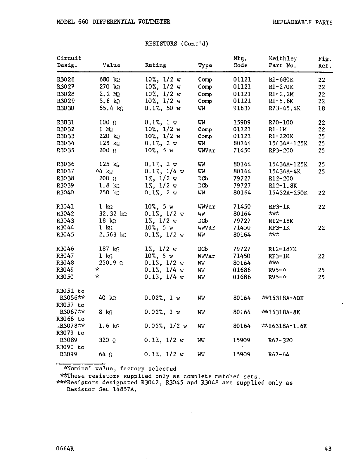
MODEL 660 DIFFERENTIAL VOLTMETER REPLACEABLE PARTS
RESISTORS (Cont'd)
Circuit
Desig.
R3026
R3027
R3028
R3029
R3030
R3031
R3032
R3033
R3034
R3035
R3036
R3037
R3038
R3039
R3040
R3041
R3042
R3043
R3044
R3045
Value Rating
680 k~
270 ko
2.2 brl
5.6 kcl
65.4 ko
100 R
ll"Q
220 kfl
125 ks2
200 n
125 ko
$04 !a
200 R
1.8 ko
250 kn
lO%, l/2 w
lO%, l/2 w
lO%, l/2 w
lO%, l/2 w
0.1/q 50 w
O.l/,, 1 w
lO%, l/2 w
lO%, l/2 w
O.l%, 2 w
lO%, 5 w
O.l%, 2 w
O.l%, l/4 w
l%, l/2 w
l%, l/2 w
O.l%, 2 w
lO%, 5 w
:2!?2 kf?
18
ko
lkl
2.563 kc
O.l%, l/2 w
l%, l/2 w
lO%, 5 w
O.l%, l/2 w
D
e
Keithley
5Pa
Mfg.
Code Part No.
Camp 01121 Rl-680K
ComP
01121
Rl-2JOK
Camp 01121 Rl-2.2M
Camp 01121 Rl-5.6K
ww
91637
ww 15909
Camp
01121
Comp 01121
R73-65.4K
R70-100
Rl-1M
Rl-220K
ww 80164 15436A-125K
War 71450
RP3-200
ww 80164 15436A-125K
ww
DCb
DCb
80164
79727
79727
15436A-4K
R12-200
R12-1.8K
ww 80164 15432A-250K
War 71450 RP3-1K
ww
DCb
War
ww
80164
79727
71450
80164
7Wd
R12-18K
RP3-1K
+k*
Fig.
Ref.
22
22
22
22
18
22
22
25
25
25
25
25
22
22
22
R3046
R304J
R3048
R3049
R3050
R3051
R3056M
to
187 k~
1kCl
250.9 n
*
*
4okI-l
l%, l/2 w
lO%, 5 w
O.l%, l/2 w
O.l%, l/4 w
O.l%, l/4 w
0.02%, 1 w
Deb
79727
R12-18JK
War 71450 RP3-1K
ww
80164
-
hw 01686 R95-*
ww 01686 R95-*
ww 80164 *16318A-40K
R3057 to
R3067*
8kQ
0.02%, 1 w
ww
80164
yW6318A-8K
R3068 to
.X3078*
1.6 kn
0.05%, l/2 w
w
80164
*16318A-1.6K
R3079 to
R3089
320 n
O.l%, l/2 w
w 15909 R67-320
R3090 to
R3099
. . _ _
XNominal value,
~.
'mese resistors supplied only as complete matched sets.
64 a
factory selected
O.l%, l/2 w
WV 15909 R67-64
*Resistors designated R3042, R3045 and R3048 are supplied only as
Resistor Set 14857A.
22
25
25
0664R
43
Page 47

REPLACEABLE PARTS
MODEL 660 DIFFERENTIAL VOLTMETER
VACUUM TUBES
Circuit
Desig.
VlOOl
v1002
v2001
v3001
V3002
v3003
v3004
v3005
V3006
V300
7
Nuder
Code
12Ax7 73445 EV-12AK7 21
6CM8 00011 EZV-6CM8 21
12BH7 85599
12AK7 73445
12AX7 73445
Mfg.
12Ax7
73445
12B4A 85599 EV-12B4A 23
12B4A
12AX7
85599
73445
OG3 73445 RV-OG3 23
Keithley
Part No.
BV-12BH7
Fig.
Ref.
23
RV-12AK7 23
EV-12AXJ
23
BV-12Ax7 23
RV-12B4A 23
BV-12AX7 23
MODEL 6601A REPLACEABLE PARTS LIST
(Refer to Schmatic Diagram 16321B for circuit designations)
TERMINALS
Circuit
Mfg.
Keithley
Desig. Description Code Part No.
JlOl Receptacle, hn modified
_-
Plug, hn, Mate of 5101, Mil. No. UG-59AfU (Mfg.
No. 7908) 91737
J102
5103
Binding Post, HI OUTPUT (Mfg. No. DF31RC) 58474 BP-8R
Binding Post, LO OUTPUT (Mfg. No. DF31BC) 58474
80164
cs-79
CS-80
BP-8B
RESISTORS
Circuit
Desig. Value Rating
Type
Mfg.
Code
Keithley
Part No.
Fig.
Ref.
RlOl 2m O.l%, 1 w ww 54294 R91-2M 26
R102 2M O.l%, 1 w m 54294 R91-2M 26
R103 2m O.l%, 1 w ww 54294 R91-2M 26
R104 2m O.l%, 1 w w 54294 R91-2M 26
R105 2m O.l%, 1 w ww 54294 R91-2M 26
R106 200 n lO%, 2 w War 71450 RP3-200 26
RlOJ 100 kc O.l%, 1 w ww 54294 R90-1OOK 26
R108
*1 kn
l%, l/2 w
Camp
00327 R12-1K
26
Qominal value, factory selected
0664R
Page 48

MODBL 660 DIFFERENTIAL VOLTMETER
REPLACEABLE PARTS
30011 Sylvania Electric Products, Inc.
Buffalo Operations of Sylvania
53021 Sangamo Electric Co.
Springfield, Ill.
Electronic Systems
Buffalo, N. Y.
54294 Shallcross Mfg. Co.
Selma, N. C.
DO327 Welwyn International, Inc.
Cleveland, Ohio
56289 Sprague Electric Co.
North Adams, Mass
01121 Allen-Bradley Corp.
Milwaukee, Wis.
58474 Superior Electric Co., The
Bristol, Corm.
01295 Texas Instruments, Inc.
Semi-.Conductor-Components Division 71400 Bussmann Mfg. Div. of
Dallas, Texas
McGraw-Edison Co.
St. Louis, MO.
01686 RCL Electronics, Inc.
Riverside, N. J.
71450 CTS Corp.
Elkhart, Ind.
02735 RCA Semiconductor and Materials
Division of Radio Corp. of America 71590 Centralab Division of
Somerville, N. J. Globe-Union, Inc.
Milwaukee, Wis.
02777 Hopkins Engineering Co.
San Fernando, Calif. 72982 Gudeman Co.
Chicago, Ill.
04713 Motorola, Inc.
Semiconductor Products Division
Phoenix, Arizona
73445 Amperex Electronic Co. Division
of North American Philips Co.,
Inc.
08520 Electronic Devices, Inc. Hicksville, N. Y.
North Ridgeville, Ohio
74970 Johnson, E. F., Co.
08804 Lamp Metals and Components
Waseca, Minn.
Department G. E. Co.
Cleveland, Ohio
75042 International Resistance Co.
Philadelphia, Pa.
12065 Transitron Electronic Corp.
East Boston, Mass.
75915 Littelfuse, Inc.
Des Plaines, Ill.
13050 Potter Co.
Wesson, Miss.
79727 Continental-Wirt Electronics Coq
Philadelphia, Pa.
14655 Cornell-Dubilier Electric Corp.
Newark, N. J.
80164 Keithley Instruments, Inc.
Cleveland, Ohio
15909 Daven Co.
Livingston, N. J.
81483 International Rectifier Corp.
El Segundo, Calif.
24655 General Radio Co.
West Concord, Mass.
82879
Royal Electric Corp.
Pawtucket, R. I.
37942 Mallory, P. R., and Co., Inc.
Indianapolis, Ind.
85599 Tube Department G. E. Co.
Schenectady, N. Y.
TABLE 7 (Sheet 1).
Code List of Suggested Manufacturers.
Supply Code fur Manufacturers, Cataloging Handbook H4-l.)
0664R
(Based on Federal
45
Page 49

REPLACEABLE PARTS
MODEL 660 DIFFBRENTIAL VOLTMETER
91637 Dale Electronics, Inc.
Columbus, Nebr.
91737 Gremar Mfg. Co.,
Inc
96733 San Fernando Electric Mfg. Co.
San Fernando, Calif.
Wakefield, Mass.
TABLE 7 (Sheet 2).
List
of Suggested Manufacturers.
Code
Supply Code for Manufacturers, Cataloging Handbook H4-1.)
(Based
on
Federal
46
0664R
Page 50

..,
.BllI
I
! :. t
/ .,.
P- t
Page 51

Page 52

-
 Loading...