

Page 1

Model 6517B
Electrometer
Reference Manual
6517B-901-01 Rev. E August 2022
tek.com/keithley
*P6517B-901-01E*
6517B-901-01E
Page 2

Electrometer
Reference Manual
Model 6517B
Page 3

© 2022, Keithley Instruments, LLC
Cleveland, Ohio, U.S.A.
All rights reserved.
Any unauthorized reproduction, photocopy, or use of the information herein, in whole or in part,
without the prior written approval of Keithley Instruments, LLC, is strictly prohibited.
These are the original instructions in English.
All Keithley Instruments product names are trademarks or registered trademarks of Keithley
Instruments, LLC. Other brand names are trademarks or registered trademarks of their respective
holders.
Document number: 6517B-901-01 Rev. E August 2022
Page 4

Safety precautions
The following safety precautions should be observed before using this product and any associated instrumentation. Although
some instruments and accessories would normally be used with nonhazardous voltages, there are situations where hazardous
conditions may be present.
This product is intended for use by personnel who recognize shock hazards and are familiar with the safety precautions required
to avoid possible injury. Read and follow all installation, operation, and maintenance information carefully before using the
product. Refer to the user documentation for complete product specifications.
If the product is used in a manner not specified, the protection provided by the product warranty may be impaired.
The types of product users are:
Responsible body is the individual or group responsible for the use and maintenance of equipment, for ensuring that the
equipment is operated within its specifications and operating limits, and for ensuring that operators are adequately trained.
Operators use the product for its intended function. They must be trained in electrical safety procedures and proper use of the
instrument. They must be protected from electric shock and contact with hazardous live circuits.
Maintenance personnel perform routine procedures on the product to keep it operating properly, for example, setting the line
voltage or replacing consumable materials. Maintenance procedures are described in the user documentation. The procedures
explicitly state if the operator may perform them. Otherwise, they should be performed only by service personnel.
Service personnel are trained to work on live circuits, perform safe installations, and repair products. Only properly trained
service personnel may perform installation and service procedures.
Keithley products are designed for use with electrical signals that are measurement, control, and data I/O connections, with low
transient overvoltages, and must not be directly connected to mains voltage or to voltage sources with high transient
overvoltages. Measurement Category II (as referenced in IEC 60664) connections require protection for high transient
overvoltages often associated with local AC mains connections. Certain Keithley measuring instruments may be connected to
mains. These instruments will be marked as category II or higher.
Unless explicitly allowed in the specifications, operating manual, and instrument labels, do not connect any instrument to mains.
Exercise extreme caution when a shock hazard is present. Lethal voltage may be present on cable connector jacks or test
fixtures. The American National Standards Institute (ANSI) states that a shock hazard exists when voltage levels greater than
30 V RMS, 42.4 V peak, or 60 VDC are present. A good safety practice is to expect that hazardous voltage is present in any
unknown circuit before measuring.
Operators of this product must be protected from electric shock at all times. The responsible body must ensure that operators
are prevented access and/or insulated from every connection point. In some cases, connections must be exposed to potential
human contact. Product operators in these circumstances must be trained to protect themselves from the risk of electric shock. If
the circuit is capable of operating at or above 1000 V, no conductive part of the circuit may be exposed.
Do not connect switching cards directly to unlimited power circuits. They are intended to be used with impedance-limited
sources. NEVER connect switching cards directly to AC mains. When connecting sources to switching cards, install protective
devices to limit fault current and voltage to the card.
Before operating an instrument, ensure that the line cord is connected to a properly-grounded power receptacle. Inspect the
connecting cables, test leads, and jumpers for possible wear, cracks, or breaks before each use.
When installing equipment where access to the main power cord is restricted, such as rack mounting, a separate main input
power disconnect device must be provided in close proximity to the equipment and within easy reach of the operator.
For maximum safety, do not touch the product, test cables, or any other instruments while power is applied to the circuit under
test. ALWAYS remove power from the entire test system and discharge any capacitors before connecting or disconnecting
cables or jumpers, installing or removing switching cards, or making internal changes, such as installing or removing jumpers.
Do not touch any object that could provide a current path to the common side of the circuit under test or power line (earth)
ground. Always make measurements with dry hands while standing on a dry, insulated surface capable of withstanding the
voltage being measured.
Page 5
For safety, instruments and accessories must be used in accordance with the operating instructions. If the instruments or
accessories are used in a manner not specified in the operating instructions, the protection provided by the equipment may be
impaired.
Do not exceed the maximum signal levels of the instruments and accessories. Maximum signal levels are defined in the
specifications and operating information and shown on the instrument panels, test fixture panels, and switching cards.
When fuses are used in a product, replace with the same type and rating for continued protection against fire hazard.
Chassis connections must only be used as shield connections for measuring circuits, NOT as protective earth (safety ground)
connections.
If you are using a test fixture, keep the lid closed while power is applied to the device under test. Safe operation requires the use
of a lid interlock.
If a screw is present, connect it to protective earth (safety ground) using the wire recommended in the user documentation.
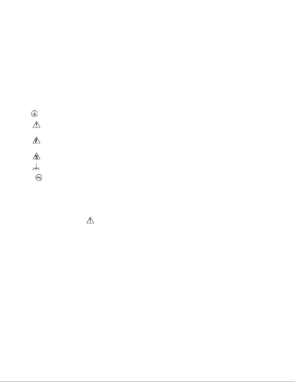
The symbol on an instrument means caution, risk of hazard. The user must refer to the operating instructions located in the
user documentation in all cases where the symbol is marked on the instrument.
The symbol on an instrument means warning, risk of electric shock. Use standard safety precautions to avoid personal
contact with these voltages.
The symbol on an instrument shows that the surface may be hot. Avoid personal contact to prevent burns.
The symbol indicates a connection terminal to the equipment frame.
If this symbol is on a product, it indicates that mercury is present in the display lamp. Please note that the lamp must be
properly disposed of according to federal, state, and local laws.
The WARNING heading in the user documentation explains hazards that might result in personal injury or death. Always read
the associated information very carefully before performing the indicated procedure.
The CAUTION heading in the user documentation explains hazards that could damage the instrument. Such damage may
invalidate the warranty.
The CAUTION heading with the symbol in the user documentation explains hazards that could result in moderate or minor
injury or damage the instrument. Always read the associated information very carefully before performing the indicated
procedure. Damage to the instrument may invalidate the warranty.
Instrumentation and accessories shall not be connected to humans.
Before performing any maintenance, disconnect the line cord and all test cables.
To maintain protection from electric shock and fire, replacement components in mains circuits — including the power
transformer, test leads, and input jacks — must be purchased from Keithley. Standard fuses with applicable national safety
approvals may be used if the rating and type are the same. The detachable mains power cord provided with the instrument may
only be replaced with a similarly rated power cord. Other components that are not safety-related may be purchased from other
suppliers as long as they are equivalent to the original component (note that selected parts should be purchased only through
Keithley to maintain accuracy and functionality of the product). If you are unsure about the applicability of a replacement
component, call a Keithley office for information.
Unless otherwise noted in product-specific literature, Keithley instruments are designed to operate indoors only, in the following
environment: Altitude at or below 2,000 m (6,562 ft); temperature 0 °C to 50 °C (32 °F to 122 °F); and pollution degree 1 or 2.
To clean an instrument, use a cloth dampened with deionized water or mild, water-based cleaner. Clean the exterior of the
instrument only. Do not apply cleaner directly to the instrument or allow liquids to enter or spill on the instrument. Products that
consist of a circuit board with no case or chassis (e.g., a data acquisition board for installation into a computer) should never
require cleaning if handled according to instructions. If the board becomes contaminated and operation is affected, the board
should be returned to the factory for proper cleaning/servicing.
Safety precaution revision as of June 2018.
Page 6

Introduction ............................................................................................................... 1-1
Welcome .............................................................................................................................. 1-1
Extended warranty ............................................................................................................... 1-1
Contact information .............................................................................................................. 1-1
Remote operations ................................................................................................... 2-1
Introduction .......................................................................................................................... 2-1
Select the communications interface ................................................................................... 2-1
GPIB communications interface ........................................................................................... 2-2
IEEE-488 bus connections ........................................................................................................ 2-2
Select the GPIB primary address .............................................................................................. 2-4
Select the GPIB data elements ................................................................................................ . 2-4
IEEE-488 front-panel operation ................................................................................................. 2-5
General bus commands ............................................................................................................ 2-6
RS-232 serial interface......................................................................................................... 2-8
RS-232 interface connections ................................................................................................... 2-8
RS-232 6517B configuration ..................................................................................................... 2-9
RS-232 computer configuration ............................................................................................... 2-10
Select the RS-232 data elements ............................................................................................ 2-10
RS-232 operating considerations ............................................................................................ 2-11
Program examples ............................................................................................................. 2-13
Changing the function and range ............................................................................................ 2-13
One-shot triggering ................................................................................................................. 2-14
Continuous triggering 1 ........................................................................................................... 2-15
Continuous triggering 2 ........................................................................................................... 2-15
Generating SRQ on buffer full ................................................................................................. 2-16
Store readings in the buffer ..................................................................................................... 2-17
Making readings with the scanner card ................................................................................... 2-18
Using the staircase sweep test sequence ............................................................................... 2-20
Measurement options ............................................................................................... 3-1
Introduction .......................................................................................................................... 3-1
Integration time .................................................................................................................... 3-1
Display resolution ................................................................................................................. 3-3
Line synchronization ............................................................................................................ 3-4
Voltage source ..................................................................................................................... 3-5
Voltage source configuration ..................................................................................................... 3-6
Sourcing options ....................................................................................................................... 3-6
Setting voltage source value ..................................................................................................... 3-9
Voltage and current limit ......................................................................................................... 3-10
Operate and standby ............................................................................................................... 3-11
Analog outputs ................................................................................................................... 3-12
2 V analog output .................................................................................................................... 3-12
Preamplifier output .................................................................................................................. 3-14
Using external feedback..................................................................................................... 3-17
Table of contents
Page 7

Table of contents Model 6517B Electrometer Reference Manual
6517B input circuitry ................................................................................................................ 3-17
Shielded fixture construction ................................................................................................... 3-18
External feedback procedure .................................................................................................. 3-20
Nonstandard coulombs ranges ............................................................................................... 3-20
Logarithmic currents ................................................................................................................ 3-21
Nondecade current gains ........................................................................................................ 3-22
Measurement range ........................................................................................................... 3-23
Range messages .................................................................................................................... 3-24
Damping ............................................................................................................................. 3-27
Zero check ......................................................................................................................... 3-28
Relative offset .................................................................................................................... 3-29
Configuring relative offset manually ........................................................................................ 3-30
Enabling relative offset and setting relative offset automatically ............................................. 3-30
Display reading with and without relative offset applied .......................................................... 3-31
Zero correct ........................................................................................................................ 3-31
Specification considerations .................................................................................................... 3-32
Accuracy calculations ......................................................................................................... 3-32
Calculating voltage accuracy................................................................................................... 3-32
Calculating current accuracy ................................................................................................... 3-32
Calculating resistance accuracy .............................................................................................. 3-33
Calculating charge accuracy ................................................................................................... 3-33
Calculating resistance/resistivity accuracy and repeatability using the alternating
polarity method ....................................................................................................................... 3-34
Measurement considerations .................................................................................. 4-1
Introduction .......................................................................................................................... 4-1
Voltage measurement considerations .................................................................................. 4-1
Loading effects .......................................................................................................................... 4-1
Guarding ................................................................................................................................... 4-2
Cable leakage resistance .......................................................................................................... 4-4
Input capacitance ...................................................................................................................... 4-4
Current measurement considerations .................................................................................. 4-4
Input bias current ...................................................................................................................... 4-4
Voltage burden .......................................................................................................................... 4-5
Noise ......................................................................................................................................... 4-5
Guarding ................................................................................................................................... 4-7
Resistance measurement considerations .......................................................................... 4-10
Leakage resistance ................................................................................................................. 4-10
Voltage coefficient ................................................................................................................... 4-11
Test voltage and electrification time ........................................................................................ 4-11
Current measurement considerations ..................................................................................... 4-11
Charge measurement considerations ................................................................................ 4-11
Input bias current .................................................................................................................... 4-12
External voltage source ........................................................................................................... 4-12
Measurement times ................................................................................................................. 4-12
Zero check hop and autodischarge hop .................................................................................. 4-12
Other measurement considerations ................................................................................... 4-12
Ground loops ........................................................................................................................... 4-13
Triboelectric effects ................................................................................................................. 4-14
Piezoelectric and stored charge effects .................................................................................. 4-14
Electrochemical effects ........................................................................................................... 4-14
Page 8

Model 6517B Electrometer Reference Manual Table of contents
Humidity .................................................................................................................................. 4-14
Light ................................ ........................................................................................................ 4-15
Electrostatic interference ......................................................................................................... 4-15
Magnetic fields ................................ ................................................................ ........................ 4-15
Electromagnetic interference................................................................................................... 4-16
Test sequences ......................................................................................................... 5-1
Introduction .......................................................................................................................... 5-1
Diode leakage current test ................................................................................................... 5-2
Diode leakage current test connections .................................................................................... 5-3
Run the diode leakage current test ........................................................................................... 5-4
Capacitor leakage current test ............................................................................................. 5-5
Capacitor leakage current test connections .............................................................................. 5-5
Run the capacitor leakage current test ...................................................................................... 5-6
Cable insulation resistance test ........................................................................................... 5-7
Cable insulation resistance test connections............................................................................. 5-7
Run the cable insulation resistance test .................................................................................... 5-8
Resistor voltage coefficient test ........................................................................................... 5-9
Resistor voltage coefficient test connections............................................................................. 5-9
Run the resistor voltage coefficient test .................................................................................. 5-10
Standard method resistivity tests ....................................................................................... 5-11
Resistivity test connections ..................................................................................................... 5-11
Run the surface or volume resistivity test ................................................................................ 5-12
Alternating polarity resistance/resistivity test ..................................................................... 5-13
Run the alternating polarity resistance/resistivity test .............................................................. 5-14
Surface insulation resistance (SIR) test ............................................................................. 5-16
Surface insulation resistance connections .............................................................................. 5-16
Run the surface insulation resistance test ............................................................................... 5-18
Square wave sweep test .................................................................................................... 5-19
Run the square wave sweep test ............................................................................................ 5-19
Staircase sweep test .......................................................................................................... 5-20
Run the staircase sweep test .................................................................................................. 5-21
Configure sequence menu ................................................................................................. 5-22
Triggering .................................................................................................................. 6-1
Introduction .......................................................................................................................... 6-1
Trigger configuration menu .................................................................................................. 6-1
Basic trigger model .............................................................................................................. 6-3
Basic trigger model configuration .............................................................................................. 6-4
Advanced trigger model ....................................................................................................... 6-5
Front-panel trigger model .......................................................................................................... 6-5
IEEE-488 trigger model ............................................................................................................. 6-7
Idle ............................................................................................................................................ 6-9
Trigger model layers ................................................................................................................. 6-9
Advanced trigger model configuration ..................................................................................... 6-10
Control sources ....................................................................................................................... 6-12
Source bypasses ..................................................................................................................... 6-14
Delays ..................................................................................................................................... 6-15
Page 9

Table of contents Model 6517B Electrometer Reference Manual
Output triggers ........................................................................................................................ 6-15
Counters.................................................................................................................................. 6-16
Continuous initiation ................................................................................................................ 6-16
Halting triggers ........................................................................................................................ 6-16
Device action ........................................................................................................................... 6-17
External triggering .............................................................................................................. 6-17
Trigger-link connector ............................................................................................................. 6-17
Asynchronous operation ......................................................................................................... 6-18
Semi-synchronous operation................................................................................................... 6-23
Buffer (data store) ..................................................................................................... 7-1
Buffer overview .................................................................................................................... 7-1
Set the type of buffer control ................................................................................................ 7-1
Buffer control step sequence..................................................................................................... 7-2
Set up a fill-and-stop buffer ....................................................................................................... 7-3
Set up a pretrigger buffer .......................................................................................................... 7-3
Set up a continuous buffer ........................................................................................................ 7-4
Set the number of readings to store ..................................................................................... 7-4
Set the real-time clock .......................................................................................................... 7-5
Set up timestamps ............................................................................................................... 7-6
Include data elements in the buffer reading ......................................................................... 7-7
Clear all buffer readings ....................................................................................................... 7-8
Reading buffer display during storage ................................................................................. 7-8
Data store configuration menu ............................................................................................. 7-9
View buffer readings from the front panel .......................................................................... 7-10
Filters and math ........................................................................................................ 8-1
Introduction .......................................................................................................................... 8-1
Filters.................................................................................................................................... 8-1
Digital filters ............................................................................................................................... 8-1
Median filter............................................................................................................................... 8-5
Configuring the filters ................................................................................................................ 8-5
Math ..................................................................................................................................... 8-7
Polynomial................................................................................................................................. 8-7
Percent ................................ ................................................................ ...................................... 8-8
Percent deviation ...................................................................................................................... 8-9
Deviation ................................................................................................................................... 8-9
Ratio ........................................................................................................................................ 8-10
Logarithmic.............................................................................................................................. 8-10
Set up no math function .......................................................................................................... 8-11
Math annunciators ................................................................................................................... 8-11
Math and actual reading display.............................................................................................. 8-11
View math readings from the front panel ................................................................................. 8-12
Limits, digital I/O, and scanning .............................................................................. 9-1
Introduction .......................................................................................................................... 9-1
Page 10

Model 6517B Electrometer Reference Manual Table of contents
Limits .................................................................................................................................... 9-1
Setting limits .............................................................................................................................. 9-2
View limit test 1 results on the front panel ................................................................................. 9-2
Limits example ................................ .......................................................................................... 9-4
Digital I/O ............................................................................................................................. 9-5
Controlling digital circuitry ......................................................................................................... 9-6
External voltage supply ............................................................................................................. 9-6
Outputs used as logic inputs ..................................................................................................... 9-8
Scanning .............................................................................................................................. 9-9
Internal scanning ....................................................................................................................... 9-9
External scanning ...................................................................................................................... 9-9
Introduction to SCPI commands ............................................................................ 10-1
Programming syntax .......................................................................................................... 10-1
Command words ..................................................................................................................... 10-1
Query commands .................................................................................................................... 10-3
Program messages ................................................................................................................. 10-4
Response messages ............................................................................................................... 10-6
Multiple response messages ................................................................................................... 10-6
Message exchange protocol ................................................................................................... 10-6
Using the SCPI command reference ................................................................................. 10-7
Command name and summary table ...................................................................................... 10-8
Command usage ..................................................................................................................... 10-9
Command details .................................................................................................................... 10-9
Example section .................................................................................................................... 10-10
Related commands list .......................................................................................................... 10-10
SCPI command reference ....................................................................................... 11-1
Introduction ........................................................................................................................ 11-1
Signal-oriented measurement commands ......................................................................... 11-1
:CONFigure:<function> ........................................................................................................... 11-2
:FETCh? .................................................................................................................................. 11-3
:MEASure[:<function>]? .......................................................................................................... 11-3
:READ? ................................................................................................................................... 11-4
SCPI conformance and command summary ..................................................................... 11-5
General notes .......................................................................................................................... 11-6
CALCulate command summary .............................................................................................. 11-6
DISPlay command summary ................................................................................................... 11-9
FORMat command summary ................................................................................................ 11-10
OUTPut command summary ................................................................................................. 11-10
ROUTe command summary.................................................................................................. 11-11
SENSe command summary - general commands ................................................................ 11-11
SENSe command summary - voltage commands ................................................................. 11-12
SENSe command summary - current commands ................................................................. 11-13
SENSe command summary - resistance commands ............................................................ 11-14
SENSe command summary - charge commands ................................................................. 11-17
SOURce command summary ................................................................................................ 11-18
STATus command summary ................................................................................................. 11-19
SYSTem command summary ............................................................................................... 11-21
TRACe command summary .................................................................................................. 11-22
TRIGger command summary - general commands .............................................................. 11-23
TRIGger command summary - ARM commands .................................................................. 11-23
Page 11

Table of contents Model 6517B Electrometer Reference Manual
TRIGger command summary - SEQuence commands ......................................................... 11-24
TSEQuence command summary .......................................................................................... 11-25
UNIT command summary ..................................................................................................... 11-28
CALCulate subsystem ...................................................................................................... 11-28
CALCulate[1] subsystem ....................................................................................................... 11-28
:CALCulate[1]:DATA? ........................................................................................................... 11-29
:CALCulate[1]:FORMat ......................................................................................................... 11-29
:CALCulate[1]:IMMediate ...................................................................................................... 11-30
:CALCulate[1]:KMATh:MA0Factor ........................................................................................ 11-31
:CALCulate[1]:KMATh:MA1Factor ........................................................................................ 11-31
:CALCulate[1]:KMATh:MA2Factor ........................................................................................ 11-32
:CALCulate[1]:KMATh:PERCent ........................................................................................... 11-32
:CALCulate[1]:REFerence ..................................................................................................... 11-33
:CALCulate[1]:STATe ............................................................................................................ 11-33
CALCulate2 subsystem ................................................................ ......................................... 11-34
:CALCulate2:DATA? ............................................................................................................. 11-34
:CALCulate2:FORMat ........................................................................................................... 11-34
:CALCulate2:IMMediate ........................................................................................................ 11-35
:CALCulate2:STATe .............................................................................................................. 11-36
CALCulate3 subsystem.................................................................................................... 11-36
:CALCulate3:BSTRobe:STATe ................................................................ ............................. 11-36
:CALCulate3:CLIMits:FAIL? .................................................................................................. 11-37
:CALCulate3:IMMediate ........................................................................................................ 11-37
:CALCulate3:LIMit2:CLEar:AUTO ......................................................................................... 11-38
:CALCulate3:LIMit2:CLEar[:IMMediate] ................................................................................ 11-39
:CALCulate3:LIMit2:FAIL?..................................................................................................... 11-39
:CALCulate3:LIMit2:LOWer:SOURce .................................................................................... 11-40
:CALCulate3:LIMit2:LOWer[:DATA] ...................................................................................... 11-41
:CALCulate3:LIMit2:STATe ................................................................................................... 11-41
:CALCulate3:LIMit2:UPPer:SOURce .................................................................................... 11-42
:CALCulate3:LIMit2:UPPer[:DATA] ....................................................................................... 11-43
:CALCulate3:LIMit[1]:CLEar:AUTO ....................................................................................... 11-44
:CALCulate3:LIMit[1]:CLEar[:IMMediate] .............................................................................. 11-44
:CALCulate3:LIMit[1]:FAIL?................................................................................................... 11-45
:CALCulate3:LIMit[1]:LOWer:SOURce .................................................................................. 11-45
:CALCulate3:LIMit[1]:LOWer[:DATA] .................................................................................... 11-46
:CALCulate3:LIMit[1]:STATe ................................................................................................. 11-47
:CALCulate3:LIMit[1]:UPPer:SOURce .................................................................................. 11-48
:CALCulate3:LIMit[1]:UPPer[:DATA] ..................................................................................... 11-49
:CALCulate3:PASS:SOURce ................................................................................................ 11-49
DISPlay subsystem .......................................................................................................... 11-51
:DISPlay:CNDisplay .............................................................................................................. 11-51
:DISPlay:ENABle ................................................................................................................... 11-51
:DISPlay:SMESsage ............................................................................................................. 11-52
:DISPlay:WINDow2:ATTRibutes? ......................................................................................... 11-52
:DISPlay:WINDow2:DATA?................................................................................................... 11-53
:DISPlay:WINDow2:TEXT:DATA .......................................................................................... 11-53
:DISPlay:WINDow2:TEXT:STATe ......................................................................................... 11-54
:DISPlay[:WINDow[1]]:ATTRibutes? ..................................................................................... 11-55
:DISPlay[:WINDow[1]]:DATA? ............................................................................................... 11-55
:DISPlay[:WINDow[1]]:TEXT:DATA ...................................................................................... 11-56
:DISPlay[:WINDow[1]]:TEXT:STATe ..................................................................................... 11-56
FORMat subsystem ......................................................................................................... 11-57
:FORMat:BORDer ................................................................................................................. 11-57
:FORMat:ELEMents .............................................................................................................. 11-58
:FORMat[:DATA] ................................................................................................................... 11-60
Page 12

Model 6517B Electrometer Reference Manual Table of contents
OUTPut subsystems ........................................................................................................ 11-63
:OUTPut1[:STATe] ................................................................................................................ 11-63
:OUTPut2:TTLX:LSENse ...................................................................................................... 11-64
ROUTe subsystem ........................................................................................................... 11-65
:ROUTe:CLOSe .................................................................................................................... 11-65
:ROUTe:CLOSe:STATe? ...................................................................................................... 11-66
:ROUTe:OPEN ...................................................................................................................... 11-66
:ROUTe:OPEN:ALL .............................................................................................................. 11-67
:ROUTe:SCAN:EXTernal ...................................................................................................... 11-67
:ROUTe:SCAN:LSELect ....................................................................................................... 11-68
:ROUTe:SCAN:SMEThod ..................................................................................................... 11-68
:ROUTe:SCAN:STIMe .......................................................................................................... 11-69
:ROUTe:SCAN:VSLimit ......................................................................................................... 11-69
:ROUTe:SCAN[:INTernal] ..................................................................................................... 11-70
SENSe[1] subsystem ....................................................................................................... 11-71
[:SENSe[1]]:<function>:APERture ......................................................................................... 11-71
[:SENSe[1]]:<function>:APERture:AUTO .............................................................................. 11-72
[:SENSe[1]]:<function>:AVERage:ADVanced:NTOLerance ................................................. 11-73
[:SENSe[1]]:<function>:AVERage:COUNt ............................................................................ 11-74
[:SENSe[1]]:<function>:AVERage:TCONtrol ......................................................................... 11-75
[:SENSe[1]]:<function>:AVERage:TYPE ............................................................................... 11-76
[:SENSe[1]]:<function>:AVERage[:STATe] ........................................................................... 11-77
[:SENSe[1]]:<function>:DAMPing .......................................................................................... 11-78
[:SENSe[1]]:<function>:DIGits ............................................................................................... 11-79
[:SENSe[1]]:<function>:DIGits:AUTO .................................................................................... 11-80
[:SENSe[1]]:<function>:MEDian:RANK ................................................................................. 11-81
[:SENSe[1]]:<function>:MEDian[:STATe] .............................................................................. 11-82
[:SENSe[1]]:<function>:NPLCycles ....................................................................................... 11-83
[:SENSe[1]]:<function>:NPLCycles:AUTO ............................................................................ 11-84
[:SENSe[1]]:<function>:RANGe:AUTO ................................................................................. 11-85
[:SENSe[1]]:<function>:RANGe:AUTO:LLIMit ....................................................................... 11-86
[:SENSe[1]]:<function>:RANGe:AUTO:ULIMit ...................................................................... 11-87
[:SENSe[1]]:<function>:RANGe[:UPPer] ............................................................................... 11-88
[:SENSe[1]]:<function>:REFerence ....................................................................................... 11-89
[:SENSe[1]]:<function>:REFerence:ACQuire ........................................................................ 11-90
[:SENSe[1]]:<function>:REFerence:STATe .......................................................................... 11-91
[:SENSe[1]]:CHARge:ADIScharge:LEVel ............................................................................. 11-92
[:SENSe[1]]:CHARge:ADIScharge[:STATe] .......................................................................... 11-92
[:SENSe[1]]:CHARge:RANGe:AUTO:LGRoup ...................................................................... 11-93
[:SENSe[1]]:DATA:FRESh? .................................................................................................. 11-93
[:SENSe[1]]:DATA[:LATest]?................................................................................................. 11-94
[:SENSe[1]]:FUNCtion ........................................................................................................... 11-95
[:SENSe[1]]:RESistance:IREFerence .................................................................................... 11-96
[:SENSe[1]:RESistance:MANual:CRANge:AUTO ................................................................. 11-97
[:SENSe[1]]:RESistance:MANual:CRANge[:UPPer] ............................................................. 11-98
[:SENSe[1]]:RESistance:MANual:VSOurce:OPERate .......................................................... 11-98
[:SENSe[1]]:RESistance:MANual:VSOurce:RANGe ............................................................. 11-99
[:SENSe[1]]:RESistance:MANual:VSOurce[:AMPLitude] ...................................................... 11-99
[:SENSe[1]]:RESistance:MSELect ...................................................................................... 11-100
[:SENSe[1]]:RESistance:RESistivity:FSELect ..................................................................... 11-100
[:SENSe[1]]:RESistance:RESistivity:M8009:RSWitch? ....................................................... 11-101
[:SENSe[1]]:RESistance:RESistivity:STHickness ................................................................ 11-102
[:SENSe[1]]:RESistance:RESistivity:USER:KSURface ....................................................... 11-102
[:SENSe[1]]:RESistance:RESistivity:USER:KVOLume ....................................................... 11-103
[:SENSe[1]]:RESistance:RESistivity:USER:RSELect .......................................................... 11-103
[:SENSe[1]]:RESistance:VSControl .................................................................................... 11-104
[:SENSe[1]:RESistance[:AUTO]:RANGe:AUTO .................................................................. 11-104
[:SENSe[1]]:RESistance[:AUTO]:RANGe:AUTO:LLIMit ...................................................... 11-105
Page 13

Table of contents Model 6517B Electrometer Reference Manual
[:SENSe[1]]:RESistance[:AUTO]:RANGe:AUTO:ULIMit ..................................................... 11-106
[:SENSe[1]]:RESistance[:AUTO]:RANGe[:UPPer] .............................................................. 11-106
[:SENSe[1]]:VOLTage[:DC]:GUARd .................................................................................... 11-107
[:SENSe[1]]:VOLTage[:DC]:XFEedback ............................................................................. 11-107
SOURce subsystem ....................................................................................................... 11-108
:SOURce:CURRent:LIMit[:STATe]? .................................................................................... 11-108
:SOURce:CURRent:RLIMit:STATe ..................................................................................... 11-108
:SOURce:TTLX:[LEVel] ................................................................ ....................................... 11-109
:SOURce:VOLTage:LIMit:STATe ........................................................................................ 11-110
:SOURce:VOLTage:LIMit[:AMPLitude] ............................................................................... 11-110
:SOURce:VOLTage:MCONnect .......................................................................................... 11-111
:SOURce:VOLTage:RANGe ............................................................................................... 11-112
:SOURce:VOLTage[:LEVel][:IMMediate][:AMPLitude] ........................................................ 11-112
STATus subsystem ........................................................................................................ 11-113
:STATus:MEASurement:CONDition? .................................................................................. 11-113
:STATus:MEASurement:ENABle ........................................................................................ 11-114
:STATus:MEASurement:NTRansition ................................................................................. 11-116
:STATus:MEASurement:PTRansition ................................................................................. 11-118
:STATus:MEASurement[:EVENt]? ...................................................................................... 11-120
:STATus:OPERation:ARM:CONDition? .............................................................................. 11-122
:STATus:OPERation:ARM:ENABle ..................................................................................... 11-123
:STATus:OPERation:ARM:NTRansition .............................................................................. 11-124
:STATus:OPERation:ARM:PTRansition .............................................................................. 11-125
:STATus:OPERation:ARM:SEQuence:CONDition? ............................................................ 11-126
:STATus:OPERation:ARM:SEQuence:ENABle ................................................................... 11-127
:STATus:OPERation:ARM:SEQuence:NTRansition ........................................................... 11-128
:STATus:OPERation:ARM:SEQuence:PTRansition ............................................................ 11-129
:STATus:OPERation:ARM:SEQuence[:EVENt]? ................................................................ 11-130
:STATus:OPERation:ARM[:EVENt]? ................................................................................... 11-131
:STATus:OPERation:CONDition? ....................................................................................... 11-132
:STATus:OPERation:ENABle .............................................................................................. 11-132
:STATus:OPERation:NTRansition ....................................................................................... 11-134
:STATus:OPERation:PTRansition ....................................................................................... 11-135
:STATus:OPERation:TRIGger:CONDition?......................................................................... 11-137
:STATus:OPERation:TRIGger:ENABle ............................................................................... 11-137
:STATus:OPERation:TRIGger:NTRansition ........................................................................ 11-138
:STATus:OPERation:TRIGger:PTRansition ........................................................................ 11-139
:STATus:OPERation:TRIGger[:EVENt]? ............................................................................. 11-140
:STATus:OPERation[:EVENt]? ............................................................................................ 11-141
:STATus:PRESet ................................................................................................................ 11-143
:STATus:QUEStionable:CONDition? .................................................................................. 11-144
:STATus:QUEStionable:ENABle ......................................................................................... 11-144
:STATus:QUEStionable:NTRansition .................................................................................. 11-146
:STATus:QUEStionable:PTRansition .................................................................................. 11-147
:STATus:QUEStionable[:EVENt]? ....................................................................................... 11-149
:STATus:QUEue:CLEar ...................................................................................................... 11-151
:STATus:QUEue:DISable .................................................................................................... 11-151
:STATus:QUEue:ENABle .................................................................................................... 11-152
:STATus:QUEue[:NEXT]? ................................................................................................... 11-153
SYSTem subsystem ....................................................................................................... 11-154
:SYSTem:ARSPeed ............................................................................................................ 11-154
:SYSTem:CLEar .................................................................................................................. 11-154
:SYSTem:DATE .................................................................................................................. 11-155
:SYSTem:ERRor? ............................................................................................................... 11-155
:SYSTem:HLControl ............................................................................................................ 11-156
:SYSTem:HSControl ........................................................................................................... 11-157
:SYSTem:INTerlock? .......................................................................................................... 11-157
:SYSTem:KEY ..................................................................................................................... 11-158
Page 14

Model 6517B Electrometer Reference Manual Table of contents
:SYSTem:LLOCkout ............................................................................................................ 11-160
:SYSTem:LOCal .................................................................................................................. 11-160
:SYSTem:LSYNc:STATe..................................................................................................... 11 -161
:SYSTem:POSetup ............................................................................................................. 11-161
:SYSTem:PRESet ............................................................................................................... 11-162
:SYSTem:REMote ............................................................................................................... 11-162
:SYSTem:RNUMber:RESet................................................................................................. 11-163
:SYSTem:TIME ................................................................................................................... 11-163
:SYSTem:TSControl ............................................................................................................ 11-164
:SYSTem:TSTamp:RELative:RESet ................................................................................... 11-164
:SYSTem:TSTamp:TYPE .................................................................................................... 11-165
:SYSTem:VERSion? ........................................................................................................... 11-165
:SYSTem:ZCHeck ............................................................................................................... 11-166
:SYSTem:ZCORrect:ACQuire ............................................................................................. 11-166
:SYSTem:ZCORrect[:STATe] .............................................................................................. 11-167
TRACe subsystem ......................................................................................................... 11-168
:TRACe:CLEar ................................ .................................................................................... 11-168
:TRACe:DATA? ................................................................................................................... 11-168
:TRACe:ELEMents .............................................................................................................. 11-169
:TRACe:FEED:CONTrol ...................................................................................................... 11-170
:TRACe:FEED:PRETrigger:AMOunt:READings .................................................................. 11-171
:TRACe:FEED:PRETrigger:AMOunt[:PERCent] ................................................................. 11 -171
:TRACe:FEED:PRETrigger:SOURce .................................................................................. 11-172
:TRACe:FREE? ................................................................................................................... 11-173
:TRACe:LAST? ................................................................................................................... 11-173
:TRACe:POINts ................................................................................................................... 11-174
:TRACe:POINts:ACTual? .................................................................................................... 11-175
:TRACe:POINts:AUTO ........................................................................................................ 11-176
:TRACe:TSTamp:FORMat .................................................................................................. 11-177
TRIGger subsystem ....................................................................................................... 11-177
:ABORt ................................................................................................................................ 11-177
:ARM:[SEQuence[1]]:LAYer2:TIMer .................................................................................... 11-178
:ARM[:SEQuence[1]]:LAYer2:COUNt ................................................................................. 11-178
:ARM[:SEQuence[1]]:LAYer2:DELay .................................................................................. 11-179
:ARM[:SEQuence[1]]:LAYer2:IMMediate ............................................................................ 11-180
:ARM[:SEQuence[1]]:LAYer2:SIGNal ................................................................................. 11-180
:ARM[:SEQuence[1]]:LAYer2:SOURce ............................................................................... 11-181
:ARM[:SEQuence[1]]:LAYer2:TCONfigure:ASYNchronous:ILINe ....................................... 11-182
:ARM[:SEQuence[1]]:LAYer2:TCONfigure:ASYNchronous:OLINe ..................................... 11-182
:ARM[:SEQuence[1]]:LAYer2:TCONfigure:DIRection ......................................................... 11-183
:ARM[:SEQuence[1]][:LAYer[1]]:COUNt ............................................................................. 11-184
:ARM[:SEQuence[1]][:LAYer[1]]:IMMediate ........................................................................ 11-184
:ARM[:SEQuence[1]][:LAYer[1]]:SIGNal ............................................................................. 11-185
:ARM[:SEQuence[1]][:LAYer[1]]:SOURce ........................................................................... 11-185
:ARM[:SEQuence[1]][:LAYer[1]]:TCONfigure:ASYNchronous:ILINe ................................... 11-186
:ARM[:SEQuence[1]][:LAYer[1]]:TCONfigure:ASYNchronous:OLINe ................................. 11-187
:ARM[:SEQuence[1]][:LAYer[1]]:TCONfigure:DIRection ..................................................... 11-187
:ARM[:SEQuence[1]][LAYer[1]]:RTCLock:DATE ................................................................. 11-188
:ARM[:SEQuence[1]][LAYer[1]]:RTCLock:TIME .................................................................. 11-189
:INITiate:CONTinuous ......................................................................................................... 11-189
:INITiate:POFLag ................................................................................................................ 11-190
:INITiate[:IMMediate] ........................................................................................................... 11-190
:SYSTem:MACRo:TRIGger:MODE ..................................................................................... 11-191
:SYSTem:MACRo:TRIGger:SOURce ................................................................................. 11-191
:SYSTem:MACRo:TRIGger:TIMer ...................................................................................... 11-192
:SYSTem:MACRo:TRIGger[:EXECute] ............................................................................... 11-193
:TRIGger:[SEQuence[1]]:TIMer ........................................................................................... 11-193
:TRIGger[:SEQuence[1]]:COUNt ......................................................................................... 11-194
:TRIGger[:SEQuence[1]]:DELay ......................................................................................... 11-194
Page 15

Table of contents Model 6517B Electrometer Reference Manual
:TRIGger[:SEQuence[1]]:IMMediate ................................................................................... 11-195
:TRIGger[:SEQuence[1]]:SIGNal ......................................................................................... 11-195
:TRIGger[:SEQuence[1]]:SOURce ...................................................................................... 11-196
:TRIGger[:SEQuence[1]]:TCONfigure:ASYNchronous:ILINe .............................................. 11-197
:TRIGger[:SEQuence[1]]:TCONfigure:ASYNchronous:OLINe ............................................ 11-197
:TRIGger[:SEQuence[1]]:TCONfigure:DIRection ................................................................ 11-198
:TRIGger[:SEQuence[1]]:TCONfigure:PROTocol ................................................................ 11-198
:TRIGger[:SEQuence[1]]:TCONfigure:SSYNchronous:LINE ............................................... 11-199
TSEQuence subsystem ................................................................................................. 11-199
:TSEQuence:ABORt ........................................................................................................... 11-200
:TSEQuence:ALTPolarity:ALTVoltage ................................................................................ 11-200
:TSEQuence:ALTPolarity:DISCard ..................................................................................... 11-201
:TSEQuence:ALTPolarity:MTIMe ........................................................................................ 11-201
:TSEQuence:ALTPolarity:OFSVoltage ................................................................................ 11-202
:TSEQuence:ALTPolarity:READings ................................................................................... 11-202
:TSEQuence:ARM ............................................................................................................... 11-203
:TSEQuence:CIResistance:SPINterval ............................................................................... 11-203
:TSEQuence:CIResistance:SPOints ................................................................................... 11-204
:TSEQuence:CIResistance:SVOLtage ................................................................................ 11-204
:TSEQuence:CLEakage:SPINterval .................................................................................... 11-205
:TSEQuence:CLEakage:SPOints ........................................................................................ 11-205
:TSEQuence:CLEakage:SVOLtage .................................................................................... 11-206
:TSEQuence:DLEakage:MDELay ....................................................................................... 11-206
:TSEQuence:DLEakage:STARt .......................................................................................... 11-207
:TSEQuence:DLEakage:STEP ............................................................................................ 11-207
:TSEQuence:DLEakage:STOP ........................................................................................... 11-208
:TSEQuence:RVCoefficient:MDELay2 ................................................................................ 11-208
:TSEQuence:RVCoefficient:MDELay[1] .............................................................................. 11-209
:TSEQuence:RVCoefficient:SVOLtage2 ............................................................................. 11-209
:TSEQuence:RVCoefficient:SVOLtage[1] ........................................................................... 11-210
:TSEQuence:SIResistance:MTIMe ..................................................................................... 11-210
:TSEQuence:SIResistance:MVOLtage ............................................................................... 11-211
:TSEQuence:SIResistance:STIMe ...................................................................................... 11-211
:TSEQuence:SIResistance:SVOLtage ................................................................................ 11-212
:TSEQuence:SQSWeep:COUNt ......................................................................................... 11-212
:TSEQuence:SQSWeep:HLEVel ......................................................................................... 11-213
:TSEQuence:SQSWeep:HTIMe .......................................................................................... 11-213
:TSEQuence:SQSWeep:LLEVel ......................................................................................... 11-214
:TSEQuence:SQSWeep:LTIMe ........................................................................................... 11-214
:TSEQuence:SRESistivity:DTIMe ....................................................................................... 11-215
:TSEQuence:SRESistivity:MTIMe ....................................................................................... 11-215
:TSEQuence:SRESistivity:MVOLtage ................................................................................. 11-216
:TSEQuence:SRESistivity:PDTime ..................................................................................... 11-216
:TSEQuence:SRESistivity:STIMe ........................................................................................ 11-217
:TSEQuence:SRESistivity:SVOLtage .................................................................................. 11-217
:TSEQuence:STSWeep:STARt ........................................................................................... 11-218
:TSEQuence:STSWeep:STEP ............................................................................................ 11-218
:TSEQuence:STSWeep:STIMe ........................................................................................... 11-219
:TSEQuence:STSWeep:STOP ............................................................................................ 11-219
:TSEQuence:TLIne ............................................................................................................. 11-220
:TSEQuence:TSOurce ........................................................................................................ 11-220
:TSEQuence:TYPE ............................................................................................................. 11-221
:TSEQuence:VRESistivity:DTIMe ....................................................................................... 11-222
:TSEQuence:VRESistivity:MTIMe ....................................................................................... 11-222
:TSEQuence:VRESistivity:MVOLtage ................................................................................. 11-222
:TSEQuence:VRESistivity:PDTime ..................................................................................... 11-223
:TSEQuence:VRESistivity:STIMe ........................................................................................ 11-223
:TSEQuence:VRESistivity:SVOLtage .................................................................................. 11-224
Page 16

Model 6517B Electrometer Reference Manual Table of contents
UNIT subsystem ............................................................................................................. 11-224
:UNIT:TEMPerature ............................................................................................................ 11-224
Common commands .............................................................................................. 12-1
Introduction ........................................................................................................................ 12-1
Common command summary ............................................................................................ 12-1
Common command descriptions ....................................................................................... 12-2
*CLS ........................................................................................................................................ 12-2
*ESE ....................................................................................................................................... 12-3
*ESR? ..................................................................................................................................... 12-5
*IDN? ...................................................................................................................................... 12-6
*OPC ....................................................................................................................................... 12-7
*OPC? ..................................................................................................................................... 12-8
*OPT? ..................................................................................................................................... 12-9
*RCL ..................................................................................................................................... 12-10
*RST ..................................................................................................................................... 12-10
*SAV ..................................................................................................................................... 12-11
*SRE ..................................................................................................................................... 12-11
*STB? .................................................................................................................................... 12-13
*TRG ..................................................................................................................................... 12-15
*TST? .................................................................................................................................... 12-15
*WAI ...................................................................................................................................... 12-16
Status model ........................................................................................................... 13-1
Introduction ........................................................................................................................ 13-1
Status structure .................................................................................................................. 13-1
Standard event status registers............................................................................................... 13-3
Operation event status registers ............................................................................................. 13-4
Condition registers ................................................................................................................ 13-10
Transition filters ..................................................................................................................... 13-10
Event registers ................................ ................................................................ ...................... 13-11
Enable registers .................................................................................................................... 13-11
Queues ............................................................................................................................. 13-12
Status byte and service request (SRQ) ........................................................................... 13-13
Status byte register ............................................................................................................... 13-14
Service request enable register ............................................................................................. 13-15
Serial poll and SRQ ............................................................................................................... 13-16
Calibration procedure ............................................................................................. 14-1
Introduction ........................................................................................................................ 14-1
Warmup time and environment .......................................................................................... 14-1
Calibration procedure ......................................................................................................... 14-2
Recommended calibration equipment ..................................................................................... 14-2
Comprehensive calibration procedure ..................................................................................... 14-3
Restoring factory defaults........................................................................................................ 14-3
Unlock calibration .................................................................................................................... 14-3
Voltage offset calibration ......................................................................................................... 14-3
Current offset calibration ......................................................................................................... 14-6
Current ranges calibration ....................................................................................................... 14-7
Page 17

Table of contents Model 6517B Electrometer Reference Manual
Charge range calibration ......................................................................................................... 14-9
Voltage measurement ranges calibration .............................................................................. 14-10
Voltage source calibration ..................................................................................................... 14-11
Temperature calibration ........................................................................................................ 14-12
Humidity calibration ............................................................................................................... 14-12
Set calibration dates .............................................................................................................. 14-12
Save calibration ..................................................................................................................... 14-12
Lock calibration ..................................................................................................................... 14-13
Partial calibration ................................................................................................................... 14-13
Calibration command reference ....................................................................................... 14-15
Voltage offset calibration commands .................................................................................... 14-15
Current offset calibration commands ..................................................................................... 14-16
Charge calibration commands ............................................................................................... 14-17
Current calibration commands .............................................................................................. 14-17
Voltage measurement calibration commands ....................................................................... 14-18
Voltage source calibration commands .................................................................................. 14-18
Humidity calibration commands ............................................................................................ 14-19
Temperature calibration commands ...................................................................................... 14-19
Miscellaneous calibration commands .................................................................................... 14-19
Calibration error codes .......................................................................................................... 14-20
Verification procedure ............................................................................................ 15-1
Introduction ........................................................................................................................ 15-1
Equipment needed for verification ........................................................................................... 15-2
Warmup time and environment ................................................................ ............................... 15-2
Considerations ................................ ................................................................ ........................ 15-3
Verification procedures ...................................................................................................... 15-3
DC voltage verification ............................................................................................................ 15-4
DC amps verification ............................................................................................................... 15-5
Charge verification .................................................................................................................. 15-8
Voltage source verification ...................................................................................................... 15-9
Temperature verification ....................................................................................................... 15-11
Humidity verification .............................................................................................................. 15-12
Resistance verification .......................................................................................................... 15-13
ASCII character codes ............................................................................................ 16-1
Introduction ........................................................................................................................ 16-1
ASCII character codes (decimal 0 to 31) ........................................................................... 16-1
ASCII character codes (decimal 32 to 95) ......................................................................... 16-2
ASCII character codes (decimal 96 to 127) ....................................................................... 16-3
IEEE-488 bus overview ........................................................................................... 17-1
Introduction ........................................................................................................................ 17-1
Bus description ................................................................................................................... 17-2
Bus lines ............................................................................................................................. 17-3
Data lines ................................................................................................................................ 17-3
Bus management lines ............................................................................................................ 17-4
Handshake lines ...................................................................................................................... 17-4
Bus commands .................................................................................................................. 17-5
Page 18

Model 6517B Electrometer Reference Manual Table of contents
Uniline commands ................................................................................................................... 17-6
Universal multiline commands ................................................................................................. 17-7
Addressed multiline commands .............................................................................................. 17-7
Addressed commands ............................................................................................................ 17-8
Unaddressed commands ........................................................................................................ 17-8
Common commands ............................................................................................................... 17-8
SCPI commands ..................................................................................................................... 17-8
Command codes ..................................................................................................................... 17-9
Typical command sequences ................................................................................................ 17-10
IEEE command groups ......................................................................................................... 17-10
IEEE-488 conformance .................................................................................................... 17-11
IEEE-488 documentation requirements ................................................................................ 17-12
Coupled commands .............................................................................................................. 17-13
Interface function codes ................................................................................................... 17-15
Page 19

In this section:
Welcome ...................................................................................1-1
Extended warranty ....................................................................1-1
Contact information ...................................................................1-1
Welcome
The 6½-digit 6517B Electrometer/High Resistance Meter provide reliable measurements of current
levels down to 10 aA (10×10
–18
A), charge levels down to 1 fC, and the highest resistance
measurements available up to 1018 Ω. The 6517B can also measure across a large voltage range, up
to 200 V, with an input impedance exceeding 200 TΩ.
Extended warranty
Additional years of warranty coverage are available on many products. These valuable contracts
protect you from unbudgeted service expenses and provide additional years of protection at a fraction
of the price of a repair. Extended warranties are available on new and existing products. Contact your
local Keithley Instruments office, sales partner, or distributor for details.
Contact information
If you have any questions after you review the information in this documentation, please contact your
local Keithley Instruments office, sales partner, or distributor. You can also call the Tektronix
corporate headquarters (toll-free inside the U.S. and Canada only) at 1-800-833-9200. For worldwide
contact numbers, visit tek.com/en/contact-tek.
Section 1
Introduction
Page 20

In this section:
Introduction ...............................................................................2-1
Select the communications interface ........................................2-1
GPIB communications interface ................................................2-2
RS-232 serial interface .............................................................2-8
Program examples ..................................................................2-13
Introduction
You can use GPIB (IEEE-488) or RS-232 remote communications with the 6517B.
The GPIB interface conforms to the IEEE-488.2-1987 standard and the SCPI 1996 (Standard
Commands for Programmable Instruments) standard. IEEE-488.2 defines a syntax for sending data
to and from instruments, how an instrument interprets this data, what registers exist to record the
state of the instrument, and a group of common commands. The SCPI standard defines a command
language protocol. It goes one step farther than IEEE-488.2 and defines a standard set of commands
to control every programmable aspect of an instrument.
The RS-232 serial interface allows you to send program messages to the instrument and receive
response messages from the instrument. You can use all commands over this serial port. The
RS-232 serial interface is based on the electrical and mechanical characteristics of the RS-232C
standard. Typically, the serial port is used with a controller that cannot accommodate an IEEE-488
bus interface, such as a laptop computer.
Select the communications interface
You can set the communications interface to be GPIB or RS-232.
Changing the communication interface re-initializes the instrument and restores the poweron defaults.
Section 2
Remote operations
Page 21
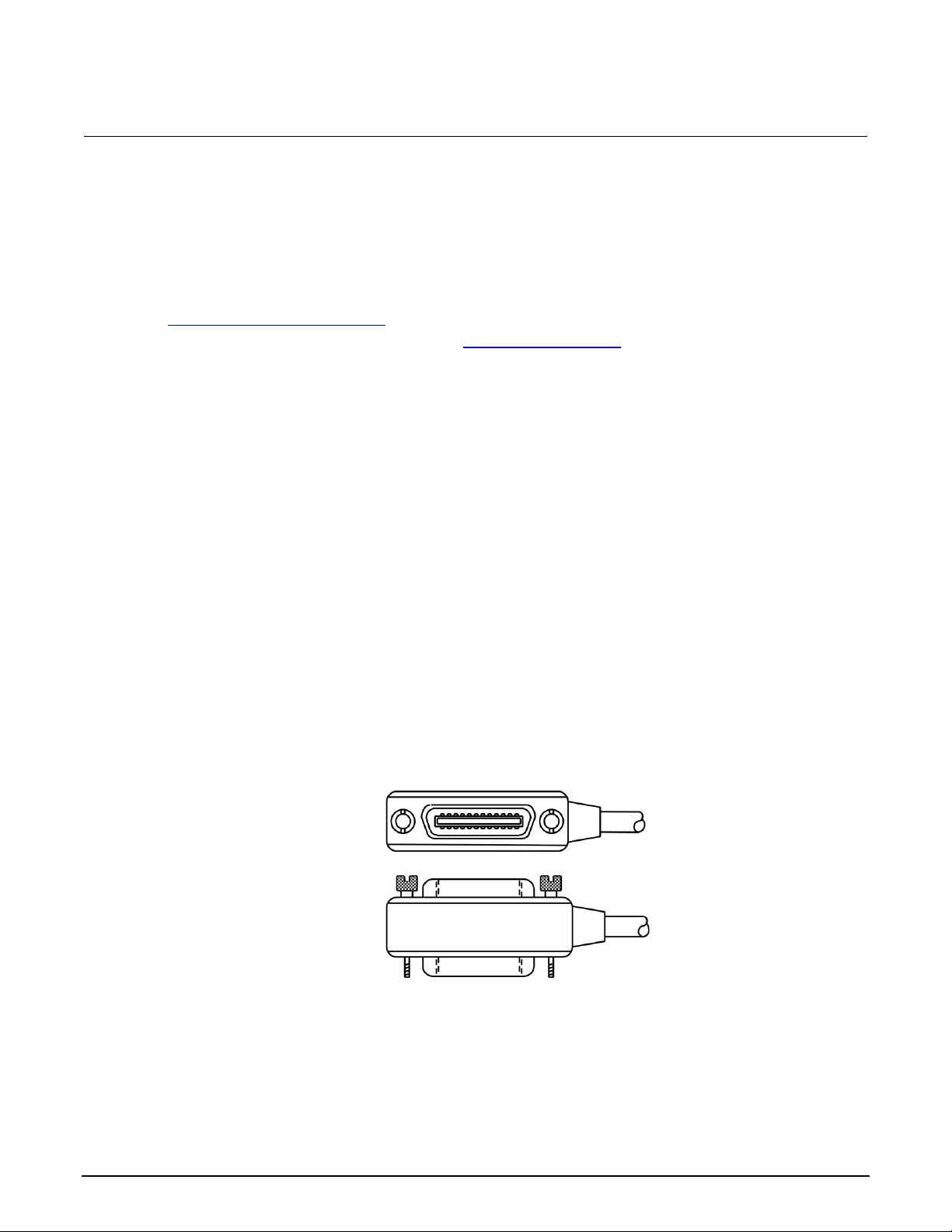
Section 2: Remote operations Model 6517B Electrometer Reference Manual
2-2 6517B-901-01 Rev. E August 2022
To select the communications interface:
1. Press the MENU key to display the MAIN MENU.
2. Select COMMUNICATION and press the ENTER key. The COMMUNICATIONS SETUP menu
is displayed.
3. Select GPIB or RS-232. Press the ENTER key.
For information on connecting and setting up the GPIB (IEEE-488) communications interface, refer to
GPIB communications interface (on page 2-2). For information on connecting and setting up the
RS-232 communications interface, refer to RS-232 serial interface (on page 2-8).
GPIB communications interface
The 6517B has a built-in GPIB (IEEE-488) interface. Over this interface, you can send data to the
instrument and receive data from the instrument.
The following information describes how to make the GPIB connections to the instrument and how to
set the GPIB address. It also describes how to set the data elements that are included with each
reading and how to operate the 6517B from the front panel when GPIB is connected. General bus
commands are also described.
IEEE-488 bus connections
The 6517B can be connected to the IEEE-488 bus through a cable equipped with standard IEEE-488
connectors. An example is shown in the following figure. The connector can be stacked to allow a
number of parallel connections to one instrument. There are two screws on each connector to ensure
that connections remain secure.
Figure 1: IEEE-488 connector
A typical connection scheme for a multi-instrument test system is shown in the following figure. It is
recommended that you stack no more than three connectors on any one instrument to avoid possible
mechanical damage.
To minimize interference caused by electromagnetic radiation, use only shielded IEEE-488 cables.
Page 22
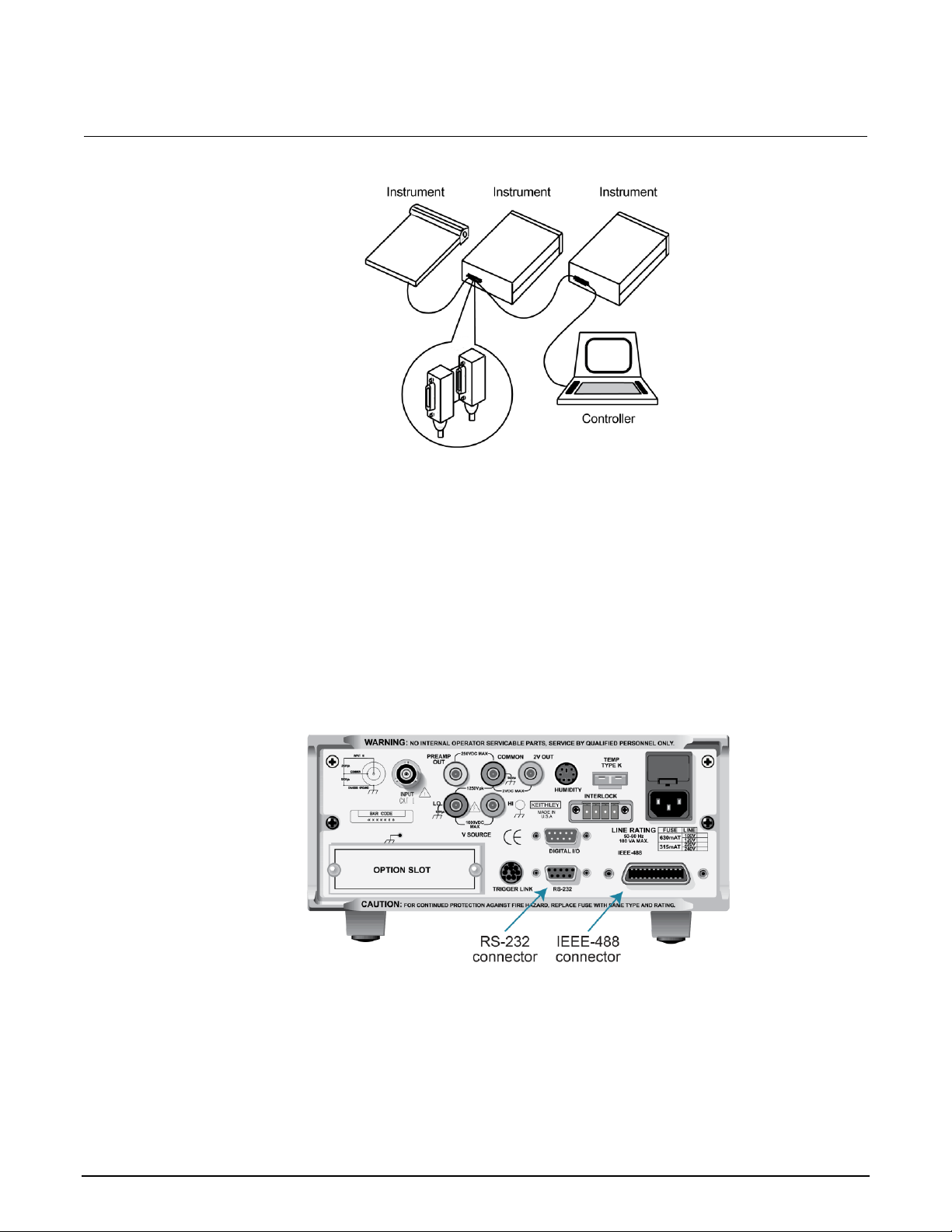
Model 6517B Electrometer Reference Manual Section 2: Remote operations
6517B-901-01 Rev. E August 2022 2-3
Figure 2: Multi-instrument connections
You can have up to 15 devices connected to a GPIB interface, including the controller. The maximum
cable length is the lesser of either:
• The number of devices multiplied by 2 m (6.5 ft)
• 20 m (65.6 ft)
You may see erratic bus operation if you ignore these limits.
To connect the 6517B to the IEEE-488 bus:
1. Line up the cable connector with the connector on the rear panel. The connector is designed so
that it fits only one way. The following figure shows the location of the IEEE-488 connector.
Figure 3: IEEE-488 and RS-232 connector locations
2. Tighten the screws securely, but do not overtighten them.
3. Add additional connectors from other instruments, as required.
4. Make certain that the other end of the cable is properly connected to the controller. Most
controllers are equipped with an IEEE-488 style connector, but a few may require a different type
of connecting cable. Consult the instruction manual for your controller for the proper
connecting method.
Page 23

Section 2: Remote operations Model 6517B Electrometer Reference Manual
2-4 6517B-901-01 Rev. E August 2022
Select the GPIB primary address
The default GPIB address is 27. You can set the address from 1 to 30 if it is unique in the system.
This address cannot conflict with an address that is assigned to another instrument or to the
GPIB controller.
GPIB controllers are usually set to 0 or 21. To be safe, do not configure any instrument to have an
address of 21.
The instrument saves the address in nonvolatile memory. It does not change when you send a reset
command or when you turn the power off and on again.
To check the present primary address or to change to a new one:
1. Press the MENU key to display the MAIN MENU.
2. Select COMMUNICATION. Press the ENTER key. The COMMUNICATIONS SETUP menu is
displayed.
3. Select GPIB. Press the ENTER key.
4. If you are switching from the RS-232 interface to the GPIB interface, the instrument is reset to the
power-on defaults. After the reset, repeat the steps above to display the GPIB menu.
5. Select ADDRESS. Press the ENTER key. The primary address of the instrument is displayed.
For example, if the instrument is set to primary address 27, the following message is displayed:
ADDRESS = 27 (0 to 30)
To change the primary address, use the ◄ and ► keys and the RANGE ▲ ▼ keys to set the
new address value. Press the ENTER key.
6. Press the EXIT key to return to the measurement display.
Select the GPIB data elements
You can select the following data elements to be sent with each reading:
• RDG: The numeric value of the reading.
• RDG#: The buffer location of the reading. The reading number can be reset to zero from the
GENERAL MENU in the TIMESTAMP option.
• UNIT: The units of the reading.
• CH#: The channel number the reading was made on.
• HUM: Relative humidity reading if the Model 6517-RH is used. The humidity sensor is enabled
from the A/D CONTROLS option in the GENERAL MENU.
Page 24

Model 6517B Electrometer Reference Manual Section 2: Remote operations
6517B-901-01 Rev. E August 2022 2-5
• ETEMP: The external temperature reading if the Model 6517-TP is used. The humidity sensor is
enabled from the A/D CONTROLS item of the GENERAL MENU.
• TIME: The real-time or relative timestamp for each reading. Timestamp type is selected from the
TIMESTAMP option in the GENERAL MENU.
• STATUS: The reading status information, such as normal reading, measurement overflow or
underflow, and relative reading.
• VSRC: The actual output level of the voltage source.
You can also select the data elements using remote communications using the :FORMat:ELEMents
(on page 11-58) command.
To set up the GPIB elements:
1. Press the MENU key.
2. Select COMMUNICATION. Press the ENTER key.
3. Select GPIB. Press the ENTER key.
4. Select ADDRESS. Press the ENTER key.
5. Select ELEMENTS. Press the ENTER key.
6. Use the ◄ and ► keys to move between the elements. Use the RANGE ▲ and ▼ keys to set
each option to y or n.
7. When the elements are set, press the ENTER key.
IEEE-488 front-panel operation
The following paragraphs discuss aspects of the front panel that are part of IEEE-488 (GPIB)
operation, including messages, status indicators, and the LOCAL key.
IEEE-488 status indicators
The REM (remote), TALK (talk), LSTN (listen), and SRQ (service request) annunciators show the
GPIB bus status.
The REM indicator is on when the instrument is in the remote state. The instrument must be
addressed to listen with REM true before the REM indicator turns on. When the instrument is in the
remote state, all front-panel keys except for the LOCAL key are locked out. When REM is turned off,
the instrument is in the local state, and front-panel operation is restored.
The TALK indicator is on when the instrument is in the talker active state. To place the instrument in
the talk state, address it to talk with the correct MTA (My Talk Address) command. TALK is off when
the instrument is in the talker idle state. To place the instrument in the talker idle state, send an UNT
(Untalk) command, address it to listen, or send the IFC (Interface Clear) command.
Page 25
Section 2: Remote operations Model 6517B Electrometer Reference Manual
2-6 6517B-901-01 Rev. E August 2022
The LSTN indicator is on when the 6517B is in the listener active state, which is activated by
addressing the instrument to listen with the correct MLA (My Listen Address) command. LSTN is off
when the instrument is in the listener idle state. To place the instrument in the listener idle state, send
UNL (Unlisten), address it to talk, or send the IFC (Interface Clear) command over the bus.
When the SRQ indicator is on, a service request was generated. You can program the instrument to
generate a service request (SRQ) when one or more errors or conditions occur. This indicator stays
on until the serial poll byte is read or all the conditions that caused the SRQ have ended.
LOCAL key
The LOCAL key cancels the remote state and restores local operation of the instrument.
Pressing LOCAL also turns off the REM indicator and returns the display to normal if a user-defined
message was displayed.
The LOCAL key is inoperative if the LLO (Local Lockout) command is in effect.
General bus commands
General commands are commands that have the same general meaning, regardless of the
instrument. The following table lists the general bus commands.
Command
Effect on 6517B
DCL
Device clear. Returns the 6517B and all devices on the GPIB to known conditions. See DCL
(on page 2-6) for details.
GET
Group execute trigger. Initiates a trigger. See GET (on page 2-7) for details.
GTL
Go to local. Cancel remote; restore 6517B front-panel operation. See GTL (on page 2-7) for
details.
IFC
Interface clear. Goes into talker and listener idle states. See IFC (on page 2-7) for details.
LLO
Local lockout. LOCAL key locked out. See LLO (on page 2-7) for details.
REN
Remote enable. Goes into remote operation when next addressed to listen. See REN (on
page 2-7) for details.
SDC
Selective device clear. Returns the 6517B to known conditions. See SDC (on page 2-8) for
details.
SPE, SPD
Serial polling. Serial polls the 6517B. See SPE, SPD (on page 2-8) for details.
DCL
Use the device clear (DCL) command to clear the GPIB interface and return it to a known state. The
DCL command is not an addressed command, so all instruments equipped to implement DCL are
returned to a known state simultaneously.
When the 6517B receives a DCL command, it:
• Clears the input buffer, output queue, and command queue
• Cancels deferred commands
• Clears any command that prevents the processing of any other device command
The DCL command does not affect instrument settings and stored data.
Page 26

Model 6517B Electrometer Reference Manual Section 2: Remote operations
6517B-901-01 Rev. E August 2022 2-7
GET
GET is a GPIB trigger that is used as an arm, scan, or measure event to control operation. The
6517B reacts to this trigger if it is the programmed control source. GET can also be used as the
pretrigger for the reading buffer.
GTL
Use the go to local (GTL) command to put an instrument that is in remote mode instrument into local
mode. Leaving the remote state also restores operation of all front-panel controls.
IFC
The controller sends the interface clear (IFC) command to place the 6517B in the talker idle state and
the listener idle state. The instrument responds to the IFC command by canceling illumination of the
front-panel TALK or LSTN lights if the instrument was previously placed in one of these states.
Transfer of command messages to the instrument and transfer of response messages from the
instrument are not interrupted by the IFC command. If transfer of a response message from the
instrument was suspended by IFC, transfer of the message resumes when the instrument is
addressed to talk. If transfer of a command message to the instrument was suspended by the IFC
command, the rest of the message can be sent when the instrument is addressed to listen.
This command does not affect the status of the instrument. Settings, data, and event registers are not
changed.
To send the IFC command, the controller needs to set the IFC line true for a minimum of 100 μs.
LLO
The LLO command prevents local operation of the instrument. After the instrument receives LLO, all
its front-panel controls except POWER are inoperative. In this state, pressing LOCAL does not
restore control to the front panel. You must use the GTL command to restore control to the
front panel.
REN
The remote enable (REN) command is sent to the 6517B by the controller to set up the instrument for
remote operation. Generally, place the instrument in the remote mode before you attempt to program
it over the bus. Setting REN to true does not place the instrument in the remote state. You must
address the instrument to listen after setting REN to true before it goes into remote operation.
Page 27

Section 2: Remote operations Model 6517B Electrometer Reference Manual
2-8 6517B-901-01 Rev. E August 2022
SDC
The selective device clear (SDC) command is an addressed command that performs essentially the
same function as the device clear (DCL) command. However, because each device must be
individually addressed, the SDC command provides a method to clear only selected instruments,
instead of clearing all instruments simultaneously with the DCL command.
When the 6517B receives an SDC command, it:
• Clears the input buffer, output queue, and command queue
• Cancels deferred commands
• Clears any command that prevents the processing of any other device command
An SDC call does not affect instrument settings and stored data.
SPE, SPD
Use the serial polling sequence to obtain the 6517B serial poll byte. The serial poll byte contains
important information about internal functions (see Status model (on page 13-1)). Generally, the serial
polling sequence is used by the controller to determine which of several instruments has requested
service with the SRQ line. The serial polling sequence may be performed at any time to obtain the
status byte from the 6517B.
RS-232 serial interface
The 6517B has a built-in RS-232 serial interface. Over this interface, you can send program
messages to the instrument and receive response messages from the instrument. You can also place
the instrument in the talk-only mode, which allows you to send readings to an external listening
device, such as a serial printer.
The serial port of the 6517B can be connected to the serial port of a computer for send/receive
operation or to a listener (such as a serial printer) for talk-only operation.
You can use the SCPI programming language over the RS-232 serial interface to communicate with
the 6517B.
RS-232 interface connections
You can connect the serial port of the 6517B to the serial port of a computer or listening device (for
example, a serial printer) using an RS-232 cable terminated with DB-9 connectors. The serial port
uses the transmit (Tx), receive (Rx), and signal ground (Gnd) lines of the RS-232 standard.
Page 28
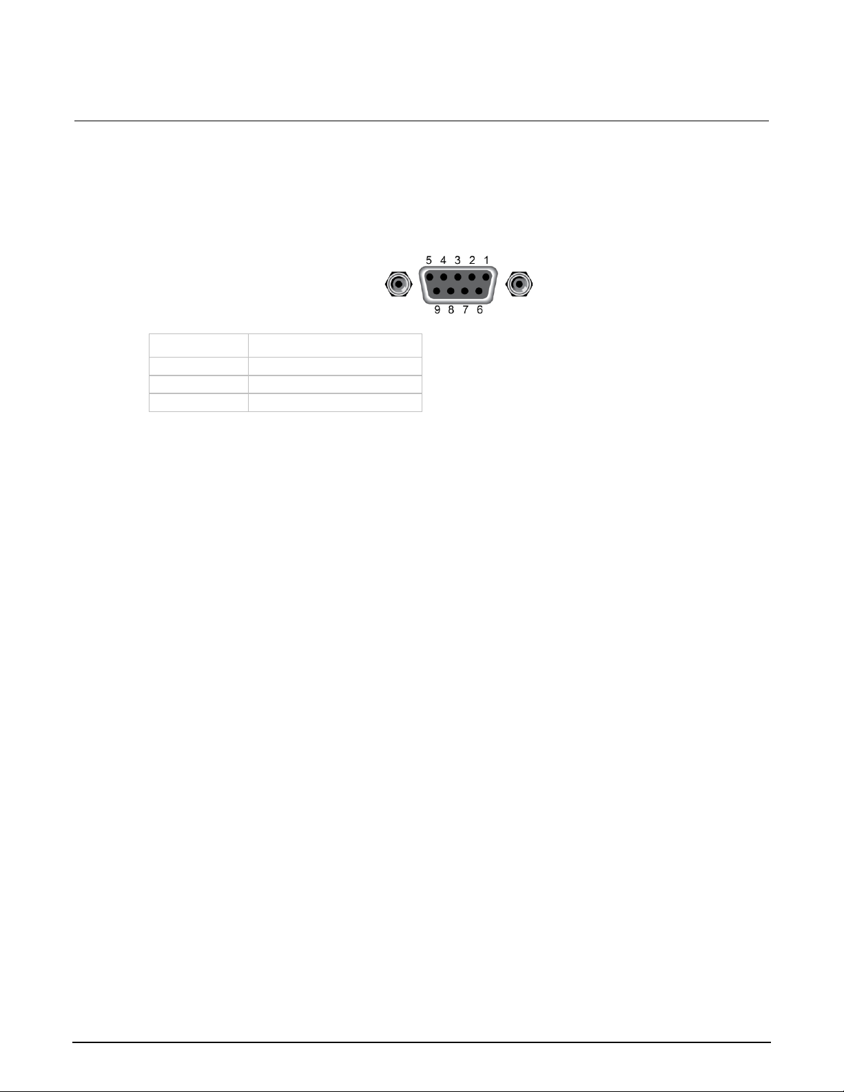
Model 6517B Electrometer Reference Manual Section 2: Remote operations
6517B-901-01 Rev. E August 2022 2-9
If your computer uses a DB-25 connector for the RS-232 interface, you need a cable or adapter with
a DB-25 connector on one end and a DB-9 connector on the other, wired straight through. Do not use
a null modem cable. The following figure shows the pins and the following tables provide pinout
identification for the 9-pin (DB-9) connector.
Figure 4: RS-232 interface connector
Pin number
Designation
2
Transmitted data (Tx)
3
Received data (Rx)
5
Signal ground (Gnd)
RS-232 6517B configuration
The RS-232 Serial Interface is selected and configured from the COMMUNICATION menu of the
MAIN MENU.
To configure the RS-232 interface on the 6517B:
1. Press the MENU key.
2. Select COMMUNICATION. Press the ENTER key.
3. Select RS-232. Press the ENTER key.
4. If you are switching from the GPIB interface to the RS-232 interface, the instrument is reset to the
power-on defaults. When reset is complete, repeat the steps above to display the RS-232
SETUP menu.
5. Select BAUD. Press the ENTER key.
6. Select 115.2K, 57.6K, 38.4K, 19.2K, 9600, 4800, 2400, 1200, 600, or 300. Press the ENTER
key.
7. Select Terminator. Press the ENTER key.
8. Select <CR>, <CR+LF>, <LF>, or <LF+CR>. Press the ENTER key.
9. Select FLOW-CTRL. Press the ENTER key.
10. Select NONE or XON-XOFF. Press the ENTER key.
11. Press the EXIT key to return to the reading display.
Page 29

Section 2: Remote operations Model 6517B Electrometer Reference Manual
2-10 6517B-901-01 Rev. E August 2022
RS-232 computer configuration
From your communications software, configure the RS-232 interface for your computer as follows:
• RTS-CTS: OFF
• XON-XON: ON
• Local echo: ON
Make sure the RS-232 parameters (baud rate, terminator, and flow control) of your computer match
the RS-232 parameters of the 6517B.
Select the RS-232 data elements
You can select the following data elements to be sent with each reading:
• RDG: The numeric value of the reading.
• RDG#: The buffer location of the reading. The reading number can be reset to zero from the
GENERAL MENU in the TIMESTAMP option.
• UNIT: The units of the reading.
• CH#: The channel number the reading was made on.
• HUM: Relative humidity reading if the Model 6517-RH is used. The humidity sensor is enabled
from the A/D CONTROLS option in the GENERAL MENU.
• ETEMP: The external temperature reading if the Model 6517-TP is used. The humidity sensor is
enabled from the A/D CONTROLS item of the GENERAL MENU.
• TIME: The real-time or relative timestamp for each reading. Timestamp type is selected from the
TIMESTAMP option in the GENERAL MENU.
• STATUS: The reading status information, such as normal reading, measurement overflow or
underflow, and relative reading.
• VSRC: The actual output level of the voltage source.
You can also select the data elements using remote communications using the :FORMat:ELEMents
(on page 11-58) command.
Page 30

Model 6517B Electrometer Reference Manual Section 2: Remote operations
6517B-901-01 Rev. E August 2022 2-11
To set up the data elements:
1. Press the MENU key.
2. Select COMMUNICATION. Press the ENTER key.
3. Select RS-232. Press the ENTER key.
4. Select ADDRESS. Press the ENTER key.
5. Select ELEMENTS. Press the ENTER key.
6. Use the ◄ and ► keys to move between the elements. Use the RANGE ▲ and ▼ keys to set
each option to y or n.
7. When the elements are set, press the ENTER key.
RS-232 operating considerations
The following topics describe considerations that apply to RS-232 operations.
Response messages (queries)
After a query command is sent and parsed, the response message is immediately sent to the
computer. The computer should be ready to receive the response message at that time.
Data format
The RS-232 interface only supports the ASCII data format. If the RS-232 interface is selected, the
data format defaults to ASCII and cannot be changed. Attempts to change the data format using
the :FORMat[:DATA] command result in an error message.
Flow control
The 6517B does not support any form of hardware flow control. Software flow control is in the form of
X_ON (Control+Q) and X_OFF (Control+S) characters. If the input queue of the 6517B becomes
more than 3/4 full (2048 characters maximum), the instrument issues an X_OFF command. The
control program should respond to this and stop sending characters until the 6517B issues the X_ON,
which it does once its input buffer has dropped below half-full. The 6517B also recognizes X_OFF and
X_ON sent from the controller. An X_OFF causes the 6517B to stop outputting characters until it sees
an X_ON. Incoming commands are processed after the <LF> character is received.
Device clear action
A Control C (^C) sent over the interface interrupts the 6517B microprocessor and forces a
device-clear action to take place. This clears any pending operation and discards any pending output.
You can also use ^X as a device-clear character.
Reception of a break condition also causes a device-clear action and displays the appropriate
error message.
Page 31

Section 2: Remote operations Model 6517B Electrometer Reference Manual
2-12 6517B-901-01 Rev. E August 2022
The 6517B signifies the completion of the device-clear action by echoing back the DCL followed by
the carriage return and line feed characters.
RS-232 SCPI commands
The following SCPI commands are unique to the RS-232 interface and cannot be used over the
GPIB interface:
• :SYSTem:LOCal: Take the 6517B out of remote operation.
• :SYSTem:REMote: Put the 6517B in remote operation.
• :SYSTem:LLOCkout: Enable or disable local lockout.
See SCPI command reference (on page 11-1) for more information on using these commands.
Error messages
The following error messages are associated with RS-232 interface operation. If one of these errors
occurs, bit B11 of the Operation Condition Register is set.
Error messages
Error code
Error message
Description
+800
RS-232 framing error detected
Start or stop bit mismatch between computer and 6517B.
+801
RS-232 parity error detected
Parity type mismatch between computer and 6517B.
+802
RS-232 overrun detected
Data received before previous data can be read.
+803
RS-232 break detected
A break occurred (device clear occurred).
+804
RS-232 noise detected
Noisy signal that could corrupt data.
+805
Invalid system communication
RS-232 interface selection lost on power-up; instrument
defaults to GPIB.
+806
RS-232 settings lost
RS-232 settings lost on power-up.
+807
RS-232 OFLO; characters lost
A character was received but discarded due to a lack of
input buffer space. Each line-feed character (<LF>)
closes a buffer and opens another. If too many line feeds
are sent in succession, all buffers are filled before they
have a chance to be read.
+808
ASCII only with RS-232
A data format other than ASCII was selected.
Page 32

Model 6517B Electrometer Reference Manual Section 2: Remote operations
6517B-901-01 Rev. E August 2022 2-13
Program examples
The following examples presume QuickBASIC version 4.5 or later and a Keithley Instruments
KPC-488.2 or CEC IEEE-488 interface card with CEC driver version 2.11 or later, with the Model
6517B at address 27 on the IEEE-488 bus.
Changing the function and range
The 6517B has independent controls for each of its measurement functions. This means, for
example, that you can enable autorange for the voltage function and disable it for the current function.
The following example program illustrates how to change the function and range. It sets the range for
several functions, then makes readings on each of those functions.
The 6517B rounds the range parameter to an integer before choosing the appropriate range.
Therefore, sending VOLTage:DC:RANGe 20.45 sets the 6517B to the 20 V range.
'Example program that demonstrates changing function and range,
'making readings on various functions.
'For QuickBASIC 4.5 and KPC-488.2/CEC interface card
'Edit the following line to point to the QuickBASIC
'libraries on your computer:
'$INCLUDE: 'c:\qb45\ieeeqb.bi'
'Initialize the interface as address 21.
CALL initialize(21, 0)
'Reset the SENSe1 subsystem settings, along with the trigger
'model. Each READ? will cause one trigger.
CALL SEND(27, "*rst", status%)
'Set range for each function to measure.
CALL SEND(27, "volt:dc:rang 10", status%)
CALL SEND(27, "curr:dc:rang 0.003", status%)
CALL SEND(27, "res:rang 10e6", status%)
'Switch to voltage and make reading.
CALL SEND(27, "func 'volt:dc';:read?", status%)
reading$ = SPACE$(80)
CALL ENTER(reading$, length%, 27, status%)
PRINT reading$
'Switch to current and make reading.
CALL SEND(27, "func 'curr:dc';:read?", status%)
reading$ = SPACE$(80)
CALL ENTER(reading$, length%, 27, status%)
PRINT reading$
'Switch to 2-wire ohms and make reading.
CALL SEND(27, "func 'res';:read?", status%)
reading$ = SPACE$(80)
CALL ENTER(reading$, length%, 27, status%)
PRINT reading$
Page 33

Section 2: Remote operations Model 6517B Electrometer Reference Manual
2-14 6517B-901-01 Rev. E August 2022
One-shot triggering
When one-shot triggering is configured, each activation of the selected trigger source produces
one reading.
Typical trigger sources for non-SCPI instruments are:
• IEEE-488 talk
• IEEE-488 Group Execute Trigger (GET)
• “X” command
Arming the instrument to respond to triggers is implicit in the non-SCPI instruments. Sending a
command to a non-SCPI instrument to change any of the trigger controls causes the instrument to
arm itself for triggers.
The SCPI trigger model implemented in the 6517B gives you:
• Explicit control over the trigger source (the TRIGger subsystem)
• A two-level control for arming the instrument for triggers
• A way to completely disable triggers
Changing any of the settings in the TRIGger subsystem does not automatically arm the 6517B
for triggers.
The following program sets up the 6517B to make one reading each time it receives an external
trigger pulse.
After the 6517B receives the INITiate command, it stops in the TRIGger layer of the trigger model,
waiting for a pulse on the external trigger jack. Each time a pulse arrives on the external trigger jack,
the 6517B makes one reading. Because TRIGger:COUNt is set to INFinity, the trigger model
never exits from the TRIGger layer. You can send the ABORt command to put the trigger model in the
idle state, which disables triggers until another INITiate command is sent.
'Example program that demonstrates one-shot external triggering.
'For QuickBASIC 4.5 and KPC-488.2/CEC interface card.
'Edit the following line to point to the QuickBASIC
'libraries on your computer.
'$INCLUDE: 'c:\qb45\ieeeqb.bi'
'Initialize the interface as address 21.
CALL initialize(21, 0)
'Reset controls in INIT, ARM;LAY1, ARM:LAY2, and TRIG subsystems
'and put trigger model in IDLE state.
CALL SEND(27, "*rst", status%)
CALL SEND(27, "trig:sour ext;coun inf", status%)
'Start everything.
CALL SEND(27, "init", status%)
Page 34

Model 6517B Electrometer Reference Manual Section 2: Remote operations
6517B-901-01 Rev. E August 2022 2-15
Continuous triggering 1
The following example program sets up the 6517B to make readings as fast as it can when it receives
an external trigger. The actual reading rate depends upon other factors, such as A/D integration time
and autorange on/off.
After the 6517B receives the INITiate command, it stops in ARM:LAYer2 of the trigger model,
waiting for a pulse on the external trigger jack. After the external trigger signal occurs, the 6517B
moves to the TRIGger layer. Since TRIGger:SOURce is set to IMMediate, a reading is triggered
immediately, with a subsequent reading triggered as soon as the previous one is finished.
'Example program to demonstrate continuous triggering.
'For QuickBASIC 4.5 and KPC-488.2/CEC interface card.
'Edit the following line to point to the QuickBASIC
'libraries on your computer.
'$INCLUDE: 'c:\qb45\ieeeqb.bi'
'Initialize the interface as address 21.
CALL initialize(21, 0)
'Reset controls in INIT, ARM;LAY1, ARM:LAY2, and TRIG subsystems
'and put trigger model in IDLE state.
CALL SEND(27, "*rst", status%)
'*RST sets TRIG:SOUR to IMM
CALL SEND(27, "arm:lay2:sour ext", status%)
CALL SEND(27, "trig:coun inf", status%)
'Start everything.
CALL SEND(27, "init", status%)
Continuous triggering 2
The following example program sets up the 6517B to make readings continuously after an external
trigger is received. The trigger rate is set to make one reading every 50 ms.
After the 6517B receives the INITiate command, it stops in ARM:LAYer2 of the trigger model,
waiting for a pulse on the external trigger jack. After the external trigger signal occurs, the 6517B
moves to the TRIGger layer. Because TRIGger:SOURce is set to TIMer, a reading is triggered
immediately, with a subsequent reading every 50 ms. Because TRIGger:COUNt has been set to
infinity, the trigger model never exits from the TRIGger layer.
'Example program to demonstrate continuous triggering
'at a specified rate.
'For QuickBASIC 4.5 and KPC-488.2/CEC interface card.
'Edit the following line to point to the QuickBASIC
'libraries on your computer
'$INCLUDE: 'c:\qb45\ieeeqb.bi'
'Initialize the interface as address 21.
CALL initialize(21, 0)
'Reset controls in INIT, ARM;LAY1, ARM:LAY2, and TRIG subsystems
'and put trigger model in IDLE state.
CALL SEND(27, "*rst", status%)
'*RST sets TRIG:SOUR to IMM.
CALL SEND(27, "arm:lay2:sour ext", status%)
CALL SEND(27, "trig:coun inf;sour tim;tim .05", status%)
'Start everything.
CALL SEND(27, "init", status%)
Page 35

Section 2: Remote operations Model 6517B Electrometer Reference Manual
2-16 6517B-901-01 Rev. E August 2022
Generating SRQ on buffer full
When your program must wait until the 6517B has completed an operation, it is more efficient to
program the 6517B to assert the IEEE-488 SRQ line when it is finished instead of repeatedly sending
serial polls to the instrument. An IEEE-488 controller typically addresses, then unaddresses the
instrument to talk each time it performs a serial poll. Repeated polling of the 6517B generally reduces
its overall reading throughput. To improve throughput, you can use the srq%() function call.
The 6517B provides a status bit for nearly every operation it performs. It can be programmed to
assert the IEEE-488 SRQ line whenever a status bit becomes true or false. The IEEE-488 controller
(your computer) can examine the state of the SRQ line without performing a serial poll, thereby
detecting when the 6517B has completed its task without interrupting operations.
The following example program segment sets up the 6517B to assert SRQ when the reading buffer
has completely filled, then arms the reading buffer, initiates readings, and waits for the 6517B to
indicate that the buffer is full.
This is not a complete program. It does not show the commands to configure the trigger model and
the reading buffer. For an example that configures the reading buffer, see Store readings in the
buffer (on page 2-17).
This example can be modified for any event in the 6517B status reporting system.
'Reset STATus subsystem (not affected by *RST).
CALL SEND(27, "stat:pres;*cls", status%)
CALL SEND(27, "stat:meas:enab 512", status%)
'Enable BFL.
CALL SEND(27, "*sre 1", status%)'enable MSB
CALL SEND(27, "trac:feed:cont next", status%)
'Start everything.
CALL SEND(27, "init", status%)
WaitSRQ:
IF (NOT(srq%)) THEN GOTO WaitSRQ
CALL SPOLL(27, poll%, status%)
IF (poll% AND 64)=0 THEN GOTO WaitSRQ
After the program has detected an asserted SRQ line, it serial polls the 6517B to determine if it is the
device requesting service. This is necessary because serial polling the 6517B causes it to stop
asserting the SRQ line. In addition, in test systems that have more than one IEEE-488 instrument
programmed to assert SRQ, your program must determine which instrument is requesting service.
Once an event register has caused a service request, it cannot cause another service request until
you clear it by reading it, such as by using STATus:MEASurement[:EVENt]? or by sending the
*CLS command.
Page 36

Model 6517B Electrometer Reference Manual Section 2: Remote operations
6517B-901-01 Rev. E August 2022 2-17
Store readings in the buffer
The reading buffer in the 6517B is flexible. You can control the size of the buffer (in readings) using
TRACe:POINts. You can use TRACe:ELEMents to store extra data stored with each reading, such
as the channel number and timestamp. Be aware that storing extra data reduces the maximum size
of the buffer.
You can also use TRACe:FEED:CONTrol to choose when and how long to record readings in
the buffer.
The following example program sets up the 6517B to make 20 readings and store them as fast as it
can into the buffer, then reads the data after the buffer fills. The readings are stored with the
timestamp and other information, but the program reads only the reading values and timestamp.
'Example program to demonstrate the reading buffer.
'For QuickBASIC 4.5 and KPC-488.2/CEC interface card.
'Edit the following line to point to the QuickBASIC
'libraries on your computer.
'$INCLUDE: 'c:\qb45\ieeeqb.bi'
'Initialize the interface as address 21.
CALL initialize(21, 0)
'Reset controls in INIT, ARM;LAY1, ARM:LAY2, and TRIG subsystems
'and put trigger model in IDLE state.
CALL SEND(27, "*rst", status%)
'Reset STATus subsystem (not affected by *RST).
CALL SEND(27, "stat:pres;*cls", status%)
CALL SEND(27, "stat:meas:enab 512", status%)
'Enable BFL.
CALL SEND(27, "*sre 1", status%)
'Enable MSB.
CALL SEND(27, "trig:coun 20", status%)
'TRACe subsystem is not affected by *RST.
CALL SEND(27, "trac:poin 20;elem none", status%)
CALL SEND(27, "trac:feed:cont next", status%)
'Start everything.
CALL SEND(27, "init", status%)
'Initialize reading$ while the 6517B is busy making readings.
reading$ = SPACE$(4000)
WaitSRQ:
IF (NOT(srq%) THEN GOTO WaitSRQ
CALL SPOLL(27, poll%, status%)
IF (poll% AND 64)=0 THEN GOTO WaitSRQ
CALL SEND(27, "trac:data?", status%)
CALL ENTER(reading$, length%, 27, status%)
PRINT reading$
Page 37

Section 2: Remote operations Model 6517B Electrometer Reference Manual
2-18 6517B-901-01 Rev. E August 2022
Making readings with the scanner card
The Model 6521 and Model 6522 are optional 10-channel scanner cards for the 6517B. Only one
channel can be closed at a time. If you close a channel while another channel is closed, the first one
opens with a break-before-make operation.
You can use the scanner card two ways. One is to issue a command to close a particular channel
before sending other commands to make readings. The other way is to program the scan list and let
the meter take care of closing a channel before making a reading.
The following example program measures voltage on channel 1, current on channel 2, and resistance
on channel 3, using the ROUTe:CLOSe command.
'Example program to demonstrate making readings on different
'scanner channels.
'For QuickBASIC 4.5 and KPC-488.2/CEC interface card.
'Edit the following line to point to the QuickBASIC
'libraries on your computer.
'$INCLUDE: 'c:\qb45\ieeeqb.bi'
'Initialize the interface as address 21.
CALL initialize(21, 0)
'Reset controls in INIT, ARM;LAY1, ARM:LAY2, and TRIG subsystems
'and put trigger model in IDLE state. Set function to voltage.
CALL SEND(27, "*rst", status%)
'Close channel 1, make a voltage reading.
CALL SEND(27, "rout:clos (@1);:read?", status%)
reading$ = SPACE$(80)
CALL ENTER(reading$, length%, 27, status%)
PRINT reading$
'Close channel 2, make a current reading.
CALL SEND(27, "func 'curr:dc'", status%)
CALL SEND(27, "rout:clos (@2);:read?", status%)
reading$ = SPACE$(80)
CALL ENTER(reading$, length%, 27, status%)
PRINT reading$
'Close channel 3, make an ohms reading.
CALL SEND(27, "func 'res'", status%)
CALL SEND(27, "rout:clos (@3);:read?", status%)
reading$ = SPACE$(80)
CALL ENTER(reading$, length%, 27, status%)
PRINT reading$
Page 38

Model 6517B Electrometer Reference Manual Section 2: Remote operations
6517B-901-01 Rev. E August 2022 2-19
The following example program sets up the 6517B using a scan list to measure dc voltage on
channels 1, 2, and 3. The meter makes ten sets of readings, with each set spaced 15 seconds apart.
Each of the three readings in each group is made as fast as possible. The 6517B stores the readings
in the buffer and asserts SRQ when the buffer is full. The program waits for the SRQ, then reads the
readings from the buffer.
'Example program to demonstrate using the scan list.
'For QuickBASIC 4.5 and KPC-488.2/CEC interface card.
'Edit the following line to point to the QuickBASIC
'libraries on your computer.
'$INCLUDE: 'c:\qb45\ieeeqb.bi'
'Initialize the interface as address 21.
CALL initialize(21, 0)
'Reset controls in INIT, ARM;LAY1, ARM:LAY2, and TRIG subsystems
'and put trigger model in IDLE state. Set the function to DCV.
CALL SEND(27, "*rst", status%)
'Reset STATus subsystem (not affected by *RST).
CALL SEND(27, "stat:pres;*cls", status%)
CALL SEND(27, "stat:meas:enab 512", status%)
'Enable BFL.
CALL SEND(27, "*sre 1", status%)
'Enable MSB.
'*RST sets TRIG:SOUR to IMM.
CALL SEND(27, "trig:coun 3", status%)
CALL SEND(27, "arm:lay2:sour tim;tim 15", status%)
CALL SEND(27, "arm:lay2:coun 10", status%)
'TRACe subsystem is not affected by *RST.
CALL SEND(27, "trac:poin 30;elem none", status%)
CALL SEND(27, "trac:feed sens1;feed:coun next", status%)
'The buffer is now armed.
CALL SEND(27, "rout:scan (@1:3)", status%)
CALL SEND(27, "rout:lsel init", status%)
'Start everything.
CALL SEND(27, "init", status%)
'Initialize reading$ while the 6517B is busy taking readings.
reading$ = SPACE$(2500)
WaitSRQ:
IF (NOT(srq%()) THEN GOTO WaitSRQ
CALL SPOLL(27, poll%, status%)
IF (poll% AND 64)=0 THEN GOTO WaitSRQ
CALL SEND(27, "form:elem read,time,chan", status%)
CALL SEND(27, "trac:data?, status%)
CALL ENTER(reading$, length%, 27, status%)
PRINT reading$
Page 39

Section 2: Remote operations Model 6517B Electrometer Reference Manual
2-20 6517B-901-01 Rev. E August 2022
Using the staircase sweep test sequence
The following program performs a staircase sweep. Using the source voltage measure current (SVMI)
method, this test measures the current through a DUT at eleven voltage steps (0 V through 10 V).
The eleven readings are stored in the buffer and displayed on the computer at the conclusion of
the test.
'Quick Basic 4.5, KPC-488.2/CEC card.
'
'$INCLUDE: 'ieeeqb.bi'
CALL initialize(21, 0)
CLS
CALL send(27, "*rst", status%)
CALL send(27, "*CLS", status%)
CALL spoll(27, KIspoll%, status%)
'Configure status model to SRQ on Buffer Full.
CALL send(27, "stat:meas:enab 512", status%)
CALL SEND(27, "*sre 1", status%)
'Set current to autorange.
CALL send(27, ":SENS:FUNC 'CURR'", status%)
CALL send(27, ":SENS:CURR:RANG:AUTO ON", status%)
'Configure Staircase Sweep from 0 V to 10 V in 1 V steps.
CALL send(27, ":TSEQ:TYPE STSW", status%)
CALL send(27, ":TSEQ:STSW:STAR 0", status%)
CALL send(27, ":TSEQ:STSW:STOP 10", status%)
CALL send(27, ":TSEQ:STSW:STEP 1", status%)
CALL send(27, ":TSEQ:STSW:STIM 0.3", status%)
CALL send(27, ":TSEQ:TSO imm", status%)
'Wait for commands to complete processing.
DATA1$ = SPACE$(600)
CALL send(27, "*OPC?", status%)
CALL enter(DATA1$, length%, 27, status%)
' Start test sequence.
CALL send(27, ":TSEQ:ARM", status%)
'Wait for SRQ (buffer full).
WaitSRQ
IF (NOT (srq%)) THEN GOTO WaitSRQ
CALL spoll(27, poll%, status%)
If (poll% AND 64) = 0 THEN GOTO WaitSRQ
'Send buffer readings to computer screen:
CALL send(27, ":TRACE:DATA?", status%)
CALL enter(DATA1$, length%, 27, status%)
A = 1
FOR I = 1 TO 11
r$ = MID$(DATA!$, A, 13)
PRINT r$
A = A + 14
NEXT I
END
Page 40

In this section:
Introduction ...............................................................................3-1
Integration time .........................................................................3-1
Display resolution ......................................................................3-3
Line synchronization .................................................................3-4
Voltage source ..........................................................................3-5
Analog outputs ........................................................................3-12
Using external feedback .........................................................3-17
Measurement range ................................................................3-23
Damping..................................................................................3-27
Zero check ..............................................................................3-28
Relative offset .........................................................................3-29
Zero correct .............................................................................3-31
Accuracy calculations .............................................................3-32
Introduction
This section contains detailed information on measurement options, such as using the voltage
source, analog output, measurement range, relative offset, and preamplifier output.
Integration time
You can select the integration time of the analog to digital (A/D) converter. This is the time the input
signal is measured and is also known as aperture. The integration time affects the amount of reading
noise and the reading rate of the instrument. The integration time is specified in parameters based on
the number of power line cycles (PLCs), where 1 PLC for 60 Hz is 16.67 ms (1/60) and 1 PLC for
50 Hz and 400 Hz is 20 ms (1/50).
The shortest amount of time, or lowest NPLC value, results in the fastest reading rate but increases
the reading noise and decreases the number of usable digits.
The longest amount of time, or highest NPLC value, provides the lowest reading noise and more
usable digits, but has the slowest reading rate.
Section 3
Measurement options
Page 41

Section 3: Measurement options Model 6517B Electrometer Reference Manual
3-2 6517B-901-01 Rev. E August 2022
From the front panel, the integration time is set using the SPEED menu of the configuration menu for
each function. You can set different integration times for each function. You can select the
following options:
• FAST: Sets integration time to 0.01 PLC. Use FAST if speed is of primary importance at the
expense of increased reading noise and less usable resolution.
• MEDIUM: Sets integration time to 0.1 PLC. Use MEDIUM when a compromise between noise
performance and speed is acceptable.
• NORMAL: Sets integration time to 1 PLC. A compromise like MEDIUM, but NORMAL provides
better noise performance at the expense of speed.
• HIACCURACY: Sets integration time to 10 PLC. Use HIACCURACY when high common-mode
and normal-mode rejection is required.
• SET-SPEED-EXACTLY: Select the PLC (0.01 to 10). Use the cursor keys and the RANGE keys
to enter the PLC value. An integer PLC value increases noise rejection. Be sure to press the
ENTER key after entering the value.
• SET-BY-RSLN: This parameter optimizes the integration time for the present resolution setting.
You can also set the speed using the SCPI commands :SENSe[1]:<function>:APERture (on page 11-
71) or [:SENSe[1]]:<function>:NPLCycles (on page 11-83).
When you use the aperture command to set the integration time, the time is set in seconds per
integration. The relationship between NPLC and aperture is expressed as follows:
Aperture =
NPLC
ƒ
Where:
• Aperture is the integration rate in seconds per integration.
• NPLC is the number of power line cycles per integration.
• ƒ is the power line frequency.
For 400 Hz line power, use 50 Hz to calculate aperture.
If line synchronization is enabled (:SYSTem:LSYNc:STATe (on page 11-161)), the integration period
does not start until the beginning of the next power line cycle. For example, if a reading is triggered at
the positive peak of a power line cycle, the integration period does start until that power line cycle is
completed. The integration period starts when the positive-going sine wave crosses zero volts.
When powering on, the instrument uses the NPLC value to determine the integration period. If the
instrument is using a different power line frequency, NPLC remains the same, but the aperture
may change.
While the instrument is processing a reading, triggers are ignored.
Page 42

Model 6517B Electrometer Reference Manual Section 3: Measurement options
6517B-901-01 Rev. E August 2022 3-3
To set the integration time from the front panel:
1. Press the CONFIG key.
2. Press the function key.
3. Select SPEED. Press the ENTER key.
4. Select the speed. Press the ENTER key.
5. Press the EXIT key to return to the measurement display.
Display resolution
The 6517B can display readings at 3.5, 4.5, 5.5, or 6.5 digit resolution. The display resolution of a
reading depends on the selected resolution setting (fixed or auto). It is also affected by the SET-BYRSLN setting of the integration time, which optimizes the integration time for the selected resolution.
The default display resolution for every function is 5.5 digits. Each function can have a different
resolution setting.
The following table summarizes the relationship between the integration time and the selected
resolution setting.
Integration times when set by resolution is enabled (all functions)
Resolution
Integration time
(NPLCs)
60 Hz aperture
(s)
50 Hz or 400 Hz
(s)
Auto*
1.00
0.016667
0.02
3.5
0.01
1.6667e-4
0.0002
4.5
0.02
3.3333e-4
0.0004
5.5
0.20
0.0033
0.004
6.5
2.00
0.0333
0.04
*With AUTO resolution selected, display resolution is set to 6.5 digits.
When automatic resolution is selected, the instrument selects the optimum resolution for the present
speed (integration period setting), as shown in the following table.
Automatic resolution (all functions)
Resolution*
Integration time
3.5
4.5
5.5
6.5
0.01 to <0.02 PLC
0.02 to <0.20 PLC
0.20 to <2.00 PLC
2.00 to 10.00 PLC
*If SET-BY-RSLN integration is selected, display resolution is 6.5 digits
and the integration time 1.0 PLC.
Page 43
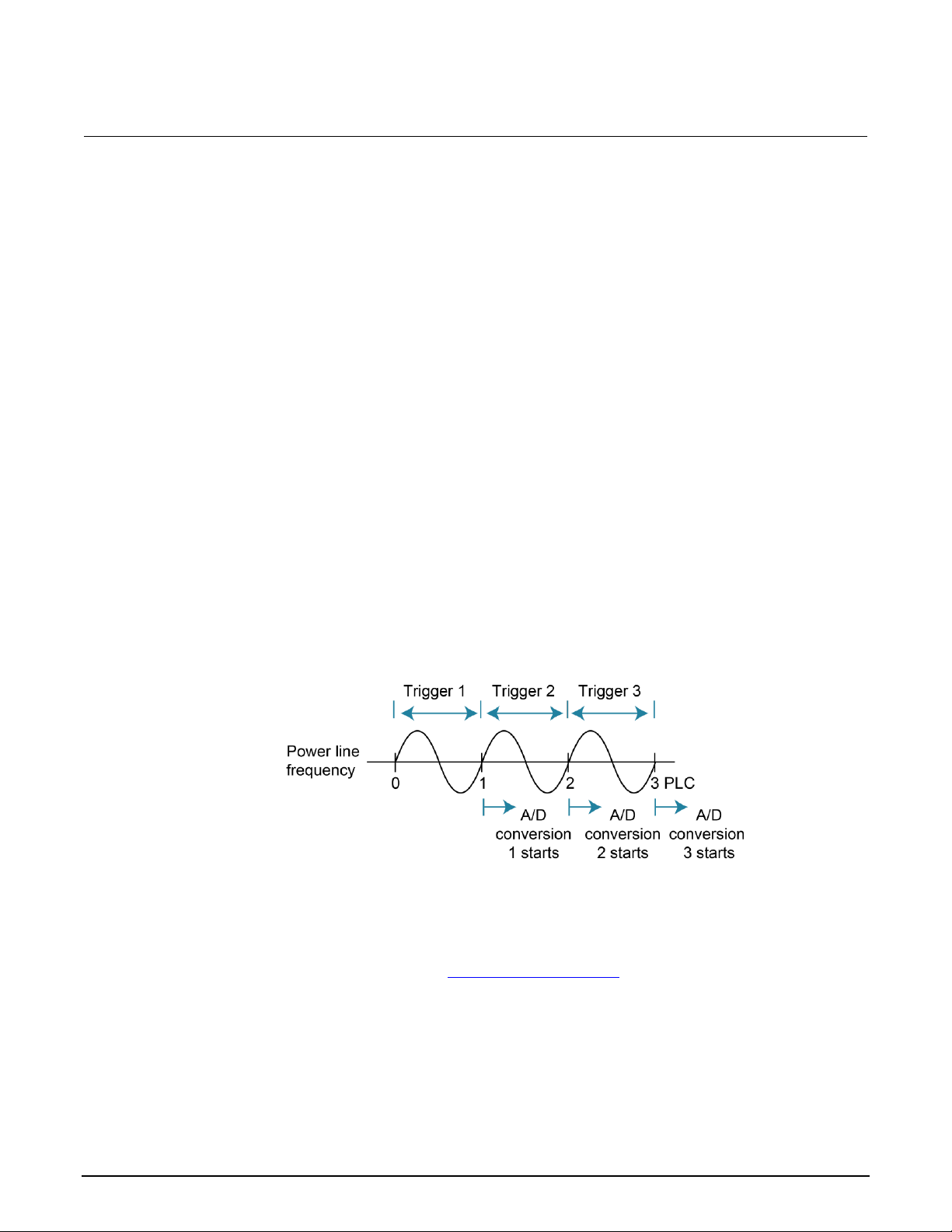
Section 3: Measurement options Model 6517B Electrometer Reference Manual
3-4 6517B-901-01 Rev. E August 2022
The display resolution for resistance readings may be less than what was selected. For example,
assume for a resistance measurement that the measured current is 00.100 pA (20 pA range, 4½ digit
resolution). If you discount the leading zeros, the current reading has a usable resolution of 2½ digits
(0.100 pA). Since the current measurement only uses 2½ digits, the resolution of the resistance
display is also limited to 2½ digits.
To set the display resolution from the front panel:
1. Press the CONFIG key.
2. Press the function key.
3. Select RESOLUTION. Press the ENTER key.
4. Select the resolution. Press the ENTER key.
5. Press the EXIT key to return to the measurement display.
Line synchronization
Synchronizing A/D conversions with the power line frequency increases common mode and normal
mode rejection. When line synchronization is enabled, measurements are initiated at the first
positive-going zero crossing of the power line cycle after the trigger. A/D conversions assume an
integration time of ≤1 power line cycle (PLC). See the following figure for an example of A/D
conversions when line synchronization is enabled.
Figure 5: Line cycle synchronization
Changing the state of line synchronization halts triggers and puts the instrument into idle. Press the
TRIG key to return to re-arm triggers.
You can set line synchronization through the front-panel menu, as described in the following
procedure, or with the remote command :SYSTem:LSYNc:STATe (on page 11-161).
Page 44
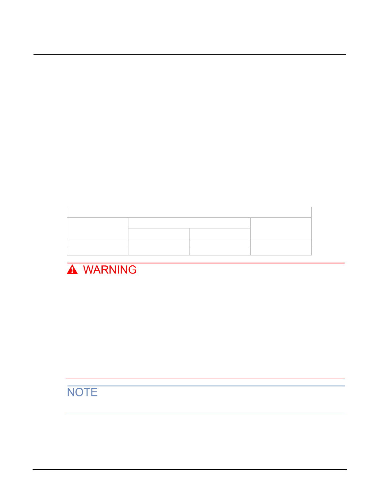
Model 6517B Electrometer Reference Manual Section 3: Measurement options
6517B-901-01 Rev. E August 2022 3-5
To enable or disable line synchronization:
1. Press the MENU key.
2. Select the GENERAL menu.
3. Select A/D-CONTROLS.
4. Select LINE-SYNC. The power line frequency is displayed.
5. Select ENABLE or DISABLE.
6. Press the ENTER key.
7. Press the EXIT key as needed to return to the measurement display.
Voltage source
The built-in bipolar 1 W voltage source of the 6517B can source up to ±1000 V (the voltage source
may reach ±1010 V if it is uncalibrated). The two voltage ranges of the voltage source are
summarized in the following table.
Voltage source ranges
Range
Maximum output
Step size
Voltage
Current
100 V
±100 V
±10 mA
5 mV
1000 V
±1000 V
±1 mA
50 mV
The maximum common-mode voltage for the voltage source is 750 V
PEAK
, so the voltage
between voltage source LO and earth (chassis) ground must never exceed 750 V
PEAK
. The
voltage between voltage source HI and earth (chassis) ground must never exceed 1750 V
PEAK
.
Exceeding these values may create a shock hazard.
Hazardous voltages may be present on the output and guard terminals. To prevent electrical
shock that could cause injury or death, NEVER make or break connections to the 6517B while
the output is on. Power off the equipment from the front panel or disconnect the main power
cord from the rear of the 6517B before handling cables connected to the outputs. Putting the
equipment in standby mode does not guarantee that the outputs are not powered if a
hardware or software fault occurs.
Capacitive inputs increase preamplifier noise, resulting in noise across the voltage source terminals.
Page 45

Section 3: Measurement options Model 6517B Electrometer Reference Manual
3-6 6517B-901-01 Rev. E August 2022
Voltage source configuration
Use the CONFIG V-SOURCE menu to configure the voltage source. The menu options are
summarized in the following table.
To display the CONFIG V-SOURCE menu, press the CONFIG key and then the OPER key.
CONFIG V-SOURCE menu
Menu item
Description
RANGE
Select the voltage source range (100 V or 1000 V). Refer to
Setting voltage source value (on page 3-9).
V-LIMIT
CONTROL
LIMIT-VALUE
Voltage limit menu:
Enable or disable voltage limit.
Set maximum absolute output limit.
Refer to Voltage and current limit (on page 3-10).
RESISTIVE-LIMIT
Enable or disable the resistive current limit.
Refer to Voltage and current limit (on page 3-10).
METER-CONNECT
Enable or disable the internal voltage source LO to ammeter
LO connection. Refer to Ammeter LO to voltage source LO
connection (on page 3-8) for detail.
Sourcing options
You can use the voltage source as an independent source or it can be internally connected to the
ammeter to source voltage and measure current (SVMI). You can also make or break the internal
connection between voltage source LO and ammeter LO.
Independent source
When the 6517B is used as an independent source, voltage is available at the V-SOURCE HI and LO
terminals on the rear panel, as shown in the following figure. In this configuration, the voltage source
functions as a stand-alone voltage source.
Figure 6: Voltage source (independent configuration)
Page 46

Model 6517B Electrometer Reference Manual Section 3: Measurement options
6517B-901-01 Rev. E August 2022 3-7
Figure 7: Voltage source (independent configuration) - equivalent circuit
The voltage source is isolated (>1 GΩ) from the measurement circuits of the 6517B when voltage
source LO is not internally connected to ammeter LO. Refer to Ammeter LO to voltage source LO
connection (on page 3-8) for more information.
Source voltage and measure current
When the 6517B sources voltage and measures current (SVMI), the voltage source LO is connected
to ammeter LO, as shown in the following figure. In this configuration, V-SOURCE HI and INPUT HI
terminals are used.
Figure 8: Voltage source (SVMI configuration)
Page 47

Section 3: Measurement options Model 6517B Electrometer Reference Manual
3-8 6517B-901-01 Rev. E August 2022
Figure 9: Voltage source (SVMI configuration) - equivalent circuit
You can make or break the voltage source LO to ammeter LO connection. Refer to Ammeter LO to
voltage source LO connection (on page 3-8) for more information.
When the voltage source is connected to a capacitor, the inherent noise of the preamplifier is
amplified. This is expected performance. Adding a series resistance does not decrease the noise.
However, shunting the output of the voltage source (HI to LO) with a 0.1 μF capacitor reduces
this noise.
Ammeter LO to voltage source LO connection
You can use the meter connect option to make or break the internal connection between voltage
source LO and ammeter LO.
To make the connection:
1. Press the CONFIG key.
2. Press the OPER key. The CONFIG V-SOURCE menu is displayed.
3. Select METER-CONNECT.
4. Select ON.
5. Press the ENTER key.
6. Press the EXIT key.
To break the connection:
1. Press the CONFIG key.
2. Press the OPER key. The CONFIG V-SOURCE menu is displayed.
3. Select METER CONNECT.
4. Select OFF.
5. Press the ENTER key.
6. Press the EXIT key.
Page 48

Model 6517B Electrometer Reference Manual Section 3: Measurement options
6517B-901-01 Rev. E August 2022 3-9
Setting voltage source value
The following information describes the voltage source display, how to select the range, and how to
set the voltage value.
Displaying the voltage source value
With the instrument in the normal measurement display state, the programmed voltage source value
is displayed on the right side of the secondary display. If the screen is in another display state, you
can display the voltage source as follows:
• If a NEXT display is open, press the NEXT key or PREV key until the voltage source is displayed.
• If you are in a menu, use the EXIT key to return to the measurement display.
When a NEXT display is open, you can temporarily display the voltage source value. Press the
VOLTAGE SOURCE ▲ or ▼ key. The voltage source value appears on the secondary display for a
few seconds.
Selecting the voltage source range
The voltage source range is selected in the CONFIG V-SOURCE menu. You can select ±100 V or
±1000 V. The 100 V range provides better resolution. The 100 V range is 5 mV compared to 50 mV
for the 1000 V range.
When the voltage source value displayed, the position of the decimal point denotes the presently
selected range. For example, a reading of 000.000 V is 0 V on the 100 V range, but a reading of
0000.00 V is 0 V on the 1000 V range.
The voltage source range cannot be changed when Auto V-source Ohms is selected.
To select the voltage source range:
1. Press the CONFIG key.
2. Press the OPER key.
3. Select RANGE.
4. Select the range.
5. Press the ENTER key.
6. Use the EXIT key to return to the previous screen.
Page 49

Section 3: Measurement options Model 6517B Electrometer Reference Manual
3-10 6517B-901-01 Rev. E August 2022
Adjusting the voltage source value
You can adjust the voltage source value. If you change the value while the 6517B is operating, the
output voltage is immediately changed to the new value.
The voltage source value cannot be changed if Auto V-source Ohms is selected.
To adjust the voltage source value:
1. Press the VOLTAGE SOURCE ▲ or ▼ key. The EDIT annunciator turns on and a digit blinks to
indicate the cursor position. The voltage source edit mode is canceled if a change is not made
within three seconds.
2. Use the ◄ and ► keys to place the cursor on the digit to be changed.
3. Use the ▲ and ▼ keys to increment or decrement the value.
4. To change the polarity, do one of the following:
▪ Increment or decrement the reading past 0 V.
▪ Place the cursor on the + or − and press the ▲ or ▼ key.
Voltage and current limit
There are absolute limits for the voltage and current sources. The voltage source has a 1 mA current
limit for the 1000 V range, a 10 mA limit for the 100 V range, and an adjustable voltage limit.
The voltage source can be set to a maximum absolute value of voltage that can be sourced. For
example, setting a value of 30 V limits the voltage output from −30 V to +30 V. If autovoltage source
ohms is enabled, the voltage limit of the voltage source can only be set to a value that is >400 V.
If the current limit is reached, the VOLTAGE SOURCE OPERATE indicator flashes. While in current
limit, the programmed voltage value is not sourced. For example, if the voltage source is programmed
to source 200 V to a 100 kΩ load, current limit occurs at approximately 100 V
(100 kΩ × 1 mA = 100 V), so the voltage source only outputs 100 V.
A resistive current limit is also available for the voltage source. When selected, a 20 MΩ resistor is
placed in series with the voltage source HI lead. This allows current to be limited. For example, with a
programmed voltage of 100 V, current is limited to 5 μA (100 V / 20 MΩ = 5 μA).
The voltage source should be used with a test fixture that incorporates a safety interlock switch, such
as the Keithley Instruments Model 8009 Resistivity Test Fixture. When the interlock is properly
installed, the 6517B cannot source voltage when the lid of the test fixture is open or ajar. Refer to
“Interlock” in the Model 6517B User's Manual for more information.
Page 50

Model 6517B Electrometer Reference Manual Section 3: Measurement options
6517B-901-01 Rev. E August 2022 3-11
Setting a voltage limit
To set a voltage limit:
1. Press the CONFIG key.
2. Press the OPER key.
3. Select V-LIMIT. Press the ENTER key.
4. Select CONTROL. Press the ENTER key.
5. To enable the voltage limit, select ON. To disable it, select OFF.
6. Press the ENTER key.
7. Select LIMIT-VALUE.
8. Use the ▲, ▼, ◄, and ► keys to set the voltage limit.
9. Press the ENTER key.
10. Use the EXIT key to return to the previous screen.
Selecting resistive current limit
When the resistance current limit is enabled, a 20 MΩ resistor is placed in series with the HI
V-SOURCE lead to extend the current limit capabilities of the voltage source. When it is disabled, a
normal current limit occurs at 1 mA.
To set a resistive current limit:
1. Press the CONFIG key.
2. Press the OPER key.
3. Select RESISTIVE-LIMIT. Press the ENTER key.
4. To enable the resistance current limit, select ON. To disable it, select OFF.
5. Press the ENTER key.
6. Use the EXIT key to return to the previous screen.
Operate and standby
Hazardous voltages may be present on the output and guard terminals. To prevent electrical
shock that could cause injury or death, NEVER make or break connections to the 6517B while
the output is on. Power off the equipment from the front panel or disconnect the main power
cord from the rear of the 6517B before handling cables connected to the outputs. Putting the
equipment in standby mode does not guarantee that the outputs are not powered if a
hardware or software fault occurs.
Page 51

Section 3: Measurement options Model 6517B Electrometer Reference Manual
3-12 6517B-901-01 Rev. E August 2022
The OPER key toggles the output between operate and standby. In operate (VOLTAGE SOURCE
OPERATE indicator on), the voltage source is applied to the output terminals. In standby, the voltage
source is removed from the rear-panel output terminals.
If the VOLTAGE SOURCE OPERATE indicator is flashing, the voltage source is in current limit.
A relay switch in series with OUTPUT HI is opened when the voltage source is placed in
standby. The transition to an open output creates a potential for noise spikes. The open
output allows dielectric absorption to recharge capacitors to unexpected voltage levels.
Analog outputs
The 6517B has two analog outputs on the rear panel. 2V OUT provides a scaled 0 V to 2 V output,
with the value of 2 V corresponding to full-range input.
PREAMP OUT is useful in situations that require buffering.
When floating input LO above 30 V
RMS
from earth ground, hazardous voltage is present at the
analog outputs. Hazardous voltage that may present a shock hazard may also be present
when the input voltage exceeds 30 V
RMS
when the voltage function is selected or when input
currents exceed 30 pA when the current function is selected.
Connecting PREAMP OUT, COMMON, or 2V OUT to earth while floating the input may damage
the instrument.
2 V analog output
The 2V OUT analog output provides a scaled 0 V to 2 V output that is noninverting in the
voltage mode.
Typical 2 V analog output values
Range
Applied signal
Nominal 2V analog output value*
20 pA
2 μA
200 V
20 nC
10.4 pA
1.65 μA
35 V
19 nC
−1.04 V
−1.65 V
0.35 V
−1.9 V
*Output values within ±15% of nominal value.
For a full-range input, the output is 2 V.
Page 52

Model 6517B Electrometer Reference Manual Section 3: Measurement options
6517B-901-01 Rev. E August 2022 3-13
The 2 V analog output signal is not corrected during calibration. Gain errors of up to 15 percent may
appear at this output, depending on function and range selection.
The output impedance is 10 kΩ. To minimize the effects of loading, the input impedance of the device
connected to 2V OUT should be as high as possible. For example, with a device with an input
impedance of 10 MΩ, the error due to loading is approximately 0.1 percent.
Connections for using the 2 V analog output are shown in the following figure.
Figure 10: Typical 2 V analog output connections
Figure 11: Typical 2 V analog output connections - equivalent circuit
Page 53

Section 3: Measurement options Model 6517B Electrometer Reference Manual
3-14 6517B-901-01 Rev. E August 2022
Preamplifier output
The PREAMP OUT terminal of the 6517B follows the signal amplitude applied to the INPUT terminal.
Some possible uses for the inverting PREAMP OUT include buffering of the input signal and guarding
in the voltage mode.
When guard is enabled, PREAMP OUT is internally connected to the inner shell of the INPUT triaxial
connector to configure the input for guarded voltage measurements. It is referenced to COMMON and
rated at 200 V dc maximum. Refer to “Shielding and guarding” in the Model 6517B User's Manual for
more information on guarding.
High voltage may be present between the PREAMP OUT and COMMON terminals. A safety
shield must be used whenever hazardous voltages (>30 V
RMS
, 42 V
PEAK
) will be present in the
test circuit. To prevent electrical shock that could cause injury or death, never use the 6517B
in a test circuit that may contain hazardous voltages without a properly installed and
configured safety shield.
Connecting PREAMP OUT, COMMON, or 2V OUT to protective earth (safety ground) while
floating the input may damage the instrument.
The PREAMP OUT accuracy is uncalibrated. Gain error of up to 15 percent may appear at this
output, depending on the function and range selection. For all voltage ranges, PREAMP OUTPUT
accuracy is typically 10 ppm.
The output resistance of PREAMP OUT is 1 Ω. The output resistance appears between input low and
analog output low to keep the resistor out of the loop when using external feedback elements. To
keep loading errors under 0.1 percent, the device connected to PREAMP OUT should have a
minimum input impedance of 100 kΩ.
Page 54

Model 6517B Electrometer Reference Manual Section 3: Measurement options
6517B-901-01 Rev. E August 2022 3-15
To prevent damage to the 6517B, do not connect a device to PREAMP OUT that draws more
than ±100 μA. For example, at 200 V, the impedance connected to PREAMP OUT must be at
least 2 MΩ (200 V / 100 μA = 2 MΩ).
Full-range outputs for voltage, current, and charge functions and ranges are listed in the
following table.
Full-range PREAMP OUT values
Function*
Range
Full-range value
Voltage
Current
Charge
2 V
20 V
200 V
2 nA, 2 μA, 2 mA
20 pA, 20 nA, 20 μA, 20 mA
200 pA, 200 nA, 200 μA
2 nC, 20 nC, 200 nC
2 μC
2 V
20 V
200 V
2 V
20 V
200 V
20 V
200 V
* The PREAMP OUT value for the resistance function corresponds to the value for the current
range that is used to make the measurement.
The connections and equivalent circuits for the preamplifier output are shown in the following figures.
Figure 12: Typical PREAMP OUT connections
Page 55

Section 3: Measurement options Model 6517B Electrometer Reference Manual
3-16 6517B-901-01 Rev. E August 2022
Figure 13: Typical voltage PREAMP OUT connections - equivalent circuit
Figure 14: Typical current and resistance PREAMP OUT connections - equivalent circuit
Figure 15: Typical charge PREAMP OUT connections - equivalent circuit
Page 56

Model 6517B Electrometer Reference Manual Section 3: Measurement options
6517B-901-01 Rev. E August 2022 3-17
Using external feedback
The external feedback feature provides a means to extend the capabilities of the 6517B. It allows
uses such as logarithmic currents, nondecade current ranges, and nonstandard charge ranges. The
following topics discuss the basic 6517B input circuitry and methods to implement these capabilities.
6517B input circuitry
A simplified diagram of the 6517B input when the external feedback feature is enabled is shown in
the following figure. An input current applied to the inverting (−) input of the operational amplifier
(op-amp) is nulled by a current feedback through the internal feedback network made up of RFB and
CFB. Because the output of the op-amp appears at the PREAMP OUT connection, this internal
network can be replaced by an external network connected between the preamplifier output and input
HI connections.
Figure 16: 6517B input circuitry (external feedback mode)
Page 57

Section 3: Measurement options Model 6517B Electrometer Reference Manual
3-18 6517B-901-01 Rev. E August 2022
When using external feedback, consider the following factors:
• The maximum current value that can be supplied by the preamplifier output is 20 mA when the
current or resistance function is selected. Maximum current is 1 mA for the voltage function. The
maximum voltage span in external feedback is ±20 V.
• The input impedance when external feedback is enabled is given by the relationship:
ZIN = ZFB / AV
Where:
▪ ZFB is the impedance of the external feedback network
▪ AV is the open-loop gain of the 6517B (typically greater than 55 × 106).
The input impedance is ZIN = 10 MΩ | ZFB when zero check is enabled.
• The voltage at the PREAMP OUT terminal is given by the formula:
V = −IZ
FB
• House any feedback elements in a suitable shielded enclosure (see Shielded fixture construction
(on page 3-18)). Insulators connected to Input HI should be made of TeflonTM or other high-quality
insulating material and should be thoroughly cleaned to maintain the high input impedance and
low input current of the 6517B. If these insulators become contaminated, they can be cleaned
with methanol and then dried with clean pressurized air.
Shielded fixture construction
Since shielding is critical for proper operation of external feedback, it is recommended that a shielded
fixture similar to the one shown in the following figure be used to house the feedback element. The
fixture is constructed of a commercially available shielded fixture, modified to replace the standard
BNC connectors with triaxial female connectors.
For convenience, a banana jack can be mounted on the box to make the PREAMP OUT connection.
Alternately, a wire can be run through a rubber grommet mounted in a hole in the side of the box.
Input low is connected to chassis ground in the shielded box. This connection can be made by using
a small solder lug secured with a screw.
Page 58

Model 6517B Electrometer Reference Manual Section 3: Measurement options
6517B-901-01 Rev. E August 2022 3-19
Figure 17: Shielded fixture construction
Item
Description
Manufacturer part number
1
Triaxial cable to 6517B input
Keithley 7078-TRX-3
2
Female triaxial
Keithley 7078-TRX-TBC
3
LO
Not applicable
4
Solder lug
Not applicable
5
Shielded box
Pomona 2390
6
Input LO (inner shield)
Not applicable
7
Input HI (center conductor)
Not applicable
8
Triaxial cable from signal
Keithley 237-ALG-2
9
Feedback element
Not applicable
10
Banana jack
Keithley BI-9-2
11
HI
Not applicable
12
To preamplifier out
Not applicable
Figure 18: Shielded fixture construction - equivalent circuit
Item
Description
Item
Description
1
Feedback element
6
Shielded fixture
2
Preamplifier out
7
237-ALG-2 cable
3
To ranging amplifier and A/D
8
GND
4
6517B input amplifier
9
LO
5
7078-TRX-3 cable
10
HI
Page 59

Section 3: Measurement options Model 6517B Electrometer Reference Manual
3-20 6517B-901-01 Rev. E August 2022
External feedback procedure
To operate the 6517B external feedback feature:
1. Connect the feedback element between the PREAMP OUT terminal and the INPUT high terminal.
2. Press the V key to select the voltage function.
3. Press the CONFIG key.
4. Press the V key. The CONFIGURE DCV menu is displayed.
5. Select EXT-FDBK.
6. Press the ENTER key.
7. Select ON.
8. Press the ENTER key.
9. Press the EXIT key to return to the measurement display. The display shows the voltage
measured at the output of the input preamplifier (PREAMP OUT).
Nonstandard coulombs ranges
Normally, the 6517B has four charge ranges, allowing it to measure charge between 10 fC and
2.1 μC. You can use different charge measurement ranges by placing an external feedback capacitor
between the PREAMP OUT and INPUT high and then placing the instrument in the external
feedback mode.
Charge is related to capacitance and voltage as follows:
Q = CV
Where:
• Q is the charge in coulombs
• C is the capacitance in farads
• V is the voltage in volts
The 6517B display reads charge directly in units determined by the value of C. For example, a 10 μF
capacitor shows a reading of 10 μC/V.
In practice, the feedback capacitor should be greater than 100 pF for feedback stability. To ensure
low leakage and low dielectric absorption, it should be of suitable dielectric material (such as
polystyrene, polypropylene, or TeflonTM). The capacitor should be mounted in a shielded fixture such
as the one shown in Shielded fixture construction (on page 3-18).
To discharge the external feedback capacitor, enable zero check. The discharge time constant is
given by t = (10 MΩ) (CFB). Allow five time constants for discharge to within 1 percent of final value.
Page 60
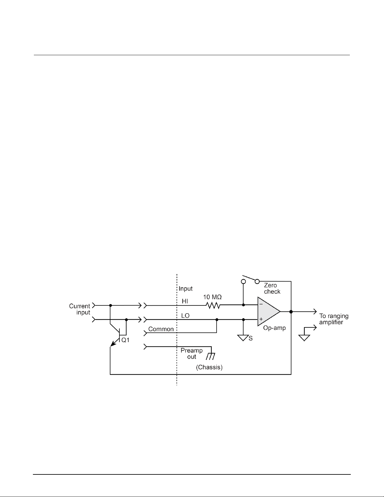
Model 6517B Electrometer Reference Manual Section 3: Measurement options
6517B-901-01 Rev. E August 2022 3-21
Logarithmic currents
The use of a diode junction in the external feedback path permits a logarithmic current-to-voltage
conversion. The relationship for a junction diode is given by the equation:
V = mkT / q ln(I/IO) + IRB
Where:
• q = Unit of charge (1.6022 × 10
−19
)
• k = Boltzmann constant (1.3806 × 10
−23
)
• T = Temperature (K)
The limitations in this equation center on the factors IO, m, and RB. IO is the extrapolated current for
VO. An empirical proportional constant, m, accounts for the different character current conduction
(recombination and diffusion mechanisms) within the junction, typically varying between 1 and 2.
Finally, RB constitutes the ohmic bulk resistance of the diode junction material. IO and RB limit the
usefulness of the junction diode at low and high currents, respectively. The factor m introduces
nonlinearities between those two extremes. Because of these limitations, most diodes have a limited
range of logarithmic behavior.
A solution to these constraints is to use a transistor configured as a transdiode in the feedback path,
as shown in the following figure.
Figure 19: Transdiode logarithmic current configuration
Analyzing the transistor in this configuration leads to the relationship:
V = kT/q[ln(I/I
O
) − ln(h
FE
/(1 + hFE))]
Where:
• h
FE
= The current gain of the transistor
Page 61

Section 3: Measurement options Model 6517B Electrometer Reference Manual
3-22 6517B-901-01 Rev. E August 2022
From this equation, proper selection of Q1 requires a device with high current gain (hFE), which is
maintained over a wide range of emitter currents. Suitable devices for this application include Analog
Devices AD812 and Precision Monolithics MAT-01. Use the enclosure in Shielded fixture construction
(on page 3-18) to shield the device.
Frequency compensation and stabilization is accomplished by adding a feedback capacitor, CFB. The
value of this capacitor depends on the transistor being used and the maximum current level expected.
Compensation at maximum current is required because the dynamic impedance is minimal at this
point. It should be noted that the response speed at lower currents is compromised due to the
increasing dynamic impedance, which is given by the following formula:
Using the above transistors, a minimum RC time constant of 100 μs at maximum input current is
used. At IIN (max) of 100 μA, this value would correspond to 0.4 μF. At 100 nA, this value increases
the RC response time constant to 100 ms. A minimum capacitance of 100 pF is recommended.
Although the input signal to this particular circuit is assumed to be a current, conversion to voltage
input could be performed by placing a shunt resistor across the input. However, you must consider
the nominal voltage burden of 1 mV as an error signal.
Further processing of the current response can be achieved by using the suppress feature. For
example, relative offset could be enabled with a reference input current applied. For all subsequent
currents, the natural logarithm of the ratio of the measured current to the suppressed current is then
displayed:
V
DISP
= V
REL
kT/q (ln (I
READ/IO
) - ln (I
REL/IO
))
= kT/q (ln (I
READ/IREL
))
= 0.26/I (ln (I
READ/IREL
)) at 25 °C
The circuit topology shown in the figure above works for positive input currents only. For bipolar input
signals, an external offset bias must be applied. You can also use a PNP transistor for Q1.
Nondecade current gains
The 6517B electrometer input uses internal decade resistance feedback networks for the current
ranges. In some applications, you may need nondecade current gains. You can use an external
feedback resistor, RFB, for this purpose, as shown in the following figure. Limitations on the magnitude
of the feedback current require that the value of RFB be greater than 100 Ω.
Page 62

Model 6517B Electrometer Reference Manual Section 3: Measurement options
6517B-901-01 Rev. E August 2022 3-23
Figure 20: Nondecade current gains
Measurement range
The measurement range affects the accuracy of the measurement and the maximum signal that can
be measured. The measurement ranges for each function are listed in the specifications.
The maximum input signal level for voltage, current, and charge measurements is 105 percent of the
measurement range. For example, the maximum signal level on the 2 V range is 2.1 V
(2 V × 1.05 = 2.1 V).
For the resistance function, each measurement range has a lower reading limit that is one decade
below the selected range. For example, the 20 MΩ range has a lower reading limit of 2 MΩ.
Resistance measurements are performed by sourcing voltage and measuring current, so resistance
ranges are current ranges calculated to show ohms units.
When autorange is selected, the instrument goes to the most sensitive range to make the
measurement. To prevent erroneous readings, allow sufficient time for settling if the instrument is
autoranging over multiple ranges or down to the lower current ranges. For the resistance function,
when autorange is selected, the instrument cannot go to the 2 TΩ, 20 TΩ, or 200 TΩ ranges because
a hazardous voltage level (400 V) may be selected by the instrument. You must select these
resistance ranges manually.
For the current, resistance, and charge functions, you can set autorange limits to speed up
measurements. Setting limits eliminates upper and lower ranges from the autorange search. For
example, if you know that readings do not exceed 1 μA, you can specify the 2 μA range to be the
maximum range. When the instrument autoranges, it does not search into the current ranges
above 2 μA.
If using autorange causes the instrument to rapidly alternate between ranges, you can reduce the
autorange speed. Change the speed to NORMal to delay measurements after a range change. The
delay helps avoid oscillation between ranges.
Page 63

Section 3: Measurement options Model 6517B Electrometer Reference Manual
3-24 6517B-901-01 Rev. E August 2022
To set the autorange limits:
1. Press the CONFIG key.
2. Press the key for the function (I, R, or Q).
3. Select AUTORANGE.
4. For the current and resistance functions, you can select:
▪ USE-ALL-RANGES: Use all ranges when autoranging.
▪ SET-LIMITS: Limit the ranges used in the autorange search. Select a minimum (MIN-AUTO)
and maximum autorange (MAX-AUTO) value.
5. For the charge function, select:
▪ LO: Limit the autorange search to the low measurement ranges (2 nC to 20 nC).
▪ HIGH: Limit the autorange search to the high measurement ranges (200 nC to 2 μC).
6. Press the ENTER key.
To set the autorange limits:
1. Press the MENU key.
2. Select GENERAL. Press the ENTER key.
3. Select A/D CONTROLS. Press the ENTER key.
4. Select AUTORANGE-SPEED. Press the ENTER key.
5. Select NORMAL to delay measurement after a range change. Select FAST to use the
fastest autorange.
Range messages
The following display messages may occur when making measurements: OVERFLOW,
UNDERFLOW, and OUT OF LIMIT. The causes of these messages and solutions are provided in the
following topics.
OVERFLOW messages
The OVERFLOW message is displayed when the integrated (average) input signal level (voltage,
current, or charge) exceeds 105% of full scale for the selected measurement range. For example, on
the 20 nA measurement range, the OVERFLOW message occurs when the integrated input level
exceeds 21 nA.
To resolve an overflow condition, select a higher measurement range, use autorange, or reduce the
magnitude of the input signal.
The OVERFLOW message does not occur during resistance or resistivity measurements.
Page 64

Model 6517B Electrometer Reference Manual Section 3: Measurement options
6517B-901-01 Rev. E August 2022 3-25
UNDERFLOW messages
This condition is similar to an overflow condition, but pertains to resistance and resistivity
measurements. When the resistance of the device under test (DUT) is too low for the selected
resistance range, the resulting current exceeds full scale and causes the UNDERFLOW message to
be displayed. This message indicates that the measured resistance is below the lower reading limit of
the selected range
The underflow condition can usually be resolved by selecting a lower resistance range or by using
autorange.
Measuring a device that is less than 2 MΩ also causes the UNDERFLOW message to be displayed.
This problem can be resolved by manually selecting the next lower range or by using autorange.
Since AUTO resistance uses the source voltage, measure current measurement method, a current
measurement overflow results in an UNDERFLOW error. Conversely, a 0 A measured current results
in an OVERFLOW error.
OUT OF LIMIT messages
An OUT OF LIMIT message indicates that a momentary or transient out-of-range condition appeared
at the input, even though the integrated (average) signal was within the full-scale range of the analog
to digital converter (A/D). It usually indicates that there is too much noise on the input signal for a
valid measurement or that the signal exceeds 120 percent of the range.
Generally, you can eliminate the out-of-limit condition by better shielding of the signal source or by
using other noise reduction methods. Refer to “Shielding and guarding” in the Model 6517B User's
Manual for more detail.
Another solution is to select the next higher range (or lower resistance range) to keep the transients
less than full scale. The 2 nA, 20 nA, and 200 nA ranges, and the resistance measurements that use
these current ranges, are particularly susceptible to this condition because of the combination of
speed and sensitivity.
A sine wave signal riding by a dc bias level demonstrates an OUT OF LIMIT reading. The following
figure shows a sine wave riding on a 20 nA bias level.
Page 65

Section 3: Measurement options Model 6517B Electrometer Reference Manual
3-26 6517B-901-01 Rev. E August 2022
Figure 21: Input signal
If this signal is measured on the 200 nA range at normal speed, it would read 20 nA (which is the dc
average). If, however, you use the 20 nA range, the positive peaks of the sine wave are clipped as
shown in the following figure.
Figure 22: Measurement on 20 nA range
Page 66

Model 6517B Electrometer Reference Manual Section 3: Measurement options
6517B-901-01 Rev. E August 2022 3-27
Clipping occurs at 110 percent of full range (22 nA on the 20 nA range). Because of clipping, the
measurement of the input signal is significantly less than 20 nA. The 6517B displays the OUT OF
LIMITS message instead of the inaccurate reading.
The positive peaks of the input signal (which exceed full scale) do not cause an overflow condition on
the 20 nA range because the average reading over the 16.67 ms integration period is less than
full scale.
You can disable the A/D hardware limit detection circuit, which in turn disables the OUT OF LIMIT
message. However, the presence of out of limit readings may result in measurements that are
slightly, moderately, or completely inaccurate. When both overflow and out of limit conditions occur,
the OUT OF LIMIT message is displayed.
To enable or disable the A/D hardware limit circuit:
1. Press the MENU key.
2. Select the GENERAL menu.
3. Select A/D CONTROLS.
4. Select LIMIT-CTRL.
5. Select TEMPERATURE.
6. Use the RANGE keys to choose ON (enabled) or OFF (disabled).
7. Press the ENTER key.
Damping
High capacitance at the input increases reading noise. This capacitance can be attributed to a long
input cable or to the capacitance of the source, or a combination of both. For the current and
resistance functions, you can enable damping to reduce this type of noise. However, damping also
slows down the response of the measurement.
Damping is not the same as filtering. Damping reduces noise caused by input capacitance. Filtering
reduces noise caused by a noisy input signal.
To enable or disable damping:
1. Press the CONFIG key.
2. Press the I or R key. The CONFIGURE CURRENT menu is displayed.
3. Select DAMPING.
4. Press the ENTER key.
5. Select ON to enable damping or OFF to disable it.
6. Press the ENTER key.
7. Press the EXIT key to return to the measurement display.
Page 67

Section 3: Measurement options Model 6517B Electrometer Reference Manual
3-28 6517B-901-01 Rev. E August 2022
Zero check
When zero check is enabled, the input amplifier is configured to shunt the input signal to low, as
shown in the following figure.
Figure 23: Equivalent input impedance with zero check enabled for voltage measurements
When you enable or disable zero check, that state is assumed regardless of the selected function.
You cannot set a unique zero check state for each function.
To ensure proper operation, always enable zero check before changing functions (V, I, R, or Q).
Press the Z-CHK key to toggle zero check. When it is enabled, the ZeroCheck message
is displayed.
For voltage, current, and resistance measurements, leave zero check enabled when connecting or
disconnecting input signals.
Figure 24: Equivalent input impedance with zero check enabled for current and resistance
measurements
When the charge function is selected, enabling zero check dissipates the charge, so the charge
reading is reset to zero. When zero check is disabled, a sudden change in the charge reading (zero
check hop) occurs. You can cancel this effect by enabling relative offset immediately after zero check
is disabled. For charge measurements, disable zero check before connecting the input signal. If zero
check is left enabled when you connect the input signal, the charge dissipates through the 10 MΩ
resistor, as shown in the following figure.
Page 68

Model 6517B Electrometer Reference Manual Section 3: Measurement options
6517B-901-01 Rev. E August 2022 3-29
Figure 25: Equivalent input impedance with zero check enabled for charge measurements
You can display the readings in zero check. Press the CONFIG key, then press the Z-CHK key to
select Yes to show zero check readings or No to hide them. When Yes is selected, ZC is displayed
next to the units of measure on the display.
Relative offset
The relative offset operation subtracts a reference value from actual readings. When relative offset is
enabled, the instrument uses the present reading as a relative value. Subsequent readings are the
difference between the actual input value and the relative offset value:
Reading with offset applied = actual input value − relative value
If math is applied, the math operation acts on the reading with offset applied:
Reading with math applied = math operation (reading with offset applied)
A relative offset value can be established for each measurement function. A relative offset value can
be as large as the highest allowable reading for the function. The state and value of relative offset for
each measurement function are saved when you change functions.
Selecting a range that cannot accommodate the offset value does not cause an overflow condition,
but it also does not increase the maximum allowable input for that range. For example, on the 2 mA
range, the 6517B still overflows for a 2.1 mA input.
Once a relative offset value is established for a measurement function, the value is the same for all
ranges. For example, if 15 V is set as the relative offset value on the 20 V range, then the offset is
also 15 V on the 200 V and 2 V ranges. Correcting zero on the lowest range corrects all ranges
because of internal scaling.
When relative offset is enabled, the voltage on the input may be significantly larger than the
displayed value. For example, if a 150 V relative offset value is stored, an applied voltage of
+175 V results in a displayed value of +25 V.
Page 69

Section 3: Measurement options Model 6517B Electrometer Reference Manual
3-30 6517B-901-01 Rev. E August 2022
Configuring relative offset manually
A bench or GPIB reset clears any stored relative offset values and disables relative offset for all
functions. Enabling relative offset also clears the existing relative offset value and selects a
new value.
If you try to enter an invalid relative offset value, a message that shows the limit for relative offset is
displayed and the operation is canceled.
To configure the relative offset manually:
1. Press the REL key to enable relative offset (the REL indicator is displayed).
2. Press the CONFIG key.
3. Press the REL key. The relative offset value for the present measurement function is displayed.
4. To change the value, use the cursor keys and the RANGE ▲ and ▼ keys.
5. Press the ENTER key. The instrument returns to the measurement display state with the new
relative offset applied.
Enabling relative offset and setting relative offset automatically
From the normal reading display, the REL key toggles the relative offset operation on and off. Each
time relative offset is enabled by the REL key, the present reading becomes the new relative offset
value for that function. To make a new reading of the relative offset value, you must disable relative
offset and then enable it.
You cannot use an overflow reading to set a relative offset.
To automatically select a relative offset value:
1. Select the lowest measurement range (2 V).
2. Press the REL key. The REL indicator turns on and the ZCor message is displayed.
If guard is enabled, the ZCor message replaces the Grd message. Guard is still enabled.
Page 70

Model 6517B Electrometer Reference Manual Section 3: Measurement options
6517B-901-01 Rev. E August 2022 3-31
Display reading with and without relative offset applied
The ACTUAL display allows you to view the reading without relative offset applied on the bottom line
of the display and the reading with offset applied on the top line.
To access this display, press either the PREV or NEXT DISPLAY key to scroll through the displays
for the selected function. An example of the relative offset and actual reading display is shown in the
following figure.
Figure 26: Relative offset and actual reading display
Zero correct
The Z-CHK and REL keys work together to cancel (zero correct) any internal offsets that might upset
accuracy for voltage and current measurements.
The instrument remains zero corrected even if a higher range is selected. If a lower range is selected,
press the REL key to zero correct the instrument again.
To zero correct the voltage or current function:
1. Select the V or I key.
2. Press the Z-CHK key to enable Zero Check.
3. Select the range for the measurement.
4. Press the REL key to zero correct the instrument. The REL indicator is lit and ZCor is displayed.
For the voltage function, ZCor replaces the display of Grd if guard is enabled.
5. Press the Z-CHK key to disable zero check.
6. Make readings.
To disable zero correct:
1. Press the Z-CHK key to enable zero check.
2. Press the REL key to turn off zero correct.
Page 71

Section 3: Measurement options Model 6517B Electrometer Reference Manual
3-32 6517B-901-01 Rev. E August 2022
Specification considerations
For making measurements "when properly zeroed", per instrument specifications:
1. Perform the zero correct procedure described in Zero correct (on page 3-31).
2. Provide a zero input from a calibration source, or short leads in the voltage function, or open
leads in the current function.
3. Press the REL key to reset the remaining measurement offsets to zero.
4. Make readings normally. The REL indicator remains on.
Repeat these steps whenever the measurement range is changed. To disable relative offset, disable
zero check and press the REL key.
Accuracy calculations
The following information discusses how to calculate accuracy.
Calculating voltage accuracy
From the specifications, voltage is calculated as follows:
Accuracy = ± (% reading + counts)
The following example shows how to compute accuracy for the 2 V range.
Assume that the voltage you are measuring is reading exactly 1.00000 V on the 2 V range. Four
counts on the 2 V range equals 0.00004 V.
From the specifications:
Accuracy
=
± (0.025% of 1 V + 4 counts)
= ± (0.00025 V + 4 counts)
= ± (0.00025 V + 0.00004 V)
= ± 0.00029 V
Therefore, the accuracy range for the 1.00000 V reading is 0.99971 V to 1.00029 V.
Calculating current accuracy
From the specifications, current is calculated as follows:
Accuracy = ± (% reading + counts)
The following example shows how to compute accuracy for the 20 mA range.
Assume that the current you are measuring is reading exactly 10.0000 mA on the 20 mA range. Five
counts on the 20 mA range equals 0.0005 mA.
Page 72

Model 6517B Electrometer Reference Manual Section 3: Measurement options
6517B-901-01 Rev. E August 2022 3-33
From the specifications:
Accuracy
=
± (0.1% of 10 mA + 5 counts)
= ± (0.01 mA + 5 counts)
= ± (0.01 mA + 0.0005 A)
= ± 0.0105 mA
Therefore, the accuracy range for the 10.0000 mA reading is 9.9895 mA to 10.0105 mA.
Calculating resistance accuracy
The following information shows how to calculate autovoltage source resistance accuracy.
From the specifications, accuracy is calculated as follows:
Accuracy = ± (% reading + counts)
The following example shows how to compute autovoltage source resistance accuracy for the 2 MΩ
range.
Assume that the resistor you are measuring is reading exactly 1.00000 MΩ on the 2 MΩ range. One
count on the 2 MΩ range (0.00001 MΩ) equals 10 Ω
From the specifications:
Accuracy
=
± (0.125% of 1 MΩ + 1 count)
= ± (1250 Ω + 1 count)
= ± (1250 Ω + 10 Ω)
= ±1260 Ω
Therefore, the accuracy range for the 1.00000 MΩ autovoltage source reading is 0.99874 MΩ to
1.00126 MΩ.
Calculating charge accuracy
From the specifications, charge is calculated as follows:
Accuracy = ± (% reading + counts)
The following example shows how to compute accuracy for the 2 μC range.
Assume that the charge you are measuring is reading exactly 1.00000 μC on the 2 μC range. Five
counts on the 2 μC range equals 0.00005 μC.
From the specifications:
Accuracy
=
± (0.4% of 1 μC + 5 counts)
= ± (0.004 μC + 5 counts)
= ± (0.004 μC + 0.00005 μC)
= ± 0.00405 μC
Therefore, the accuracy range for the 1.00000 μC reading is 0.99595 μC to 1.00405 μC.
Page 73

Section 3: Measurement options Model 6517B Electrometer Reference Manual
3-34 6517B-901-01 Rev. E August 2022
Calculating resistance/resistivity accuracy and repeatability using
the alternating polarity method
From the specifications, accuracy and repeatability when using a Model 8009 test fixture are
calculated as follows:
Repeatability: IBG × R/ V
ALT
+ 0.1% (1 )
(instrument temperature constant ±1 °C)
Accuracy: (V
SRC
Err + I
MEAS
Err × R)/V
ALT
Where:
• I
BG
is a measured, typical background current noise from the sample and fixture
• V
ALT
is the alternating polarity voltage used
• V
SRC
Err is the accuracy (in volts) of the voltage source using V
ALT
as the setting
• I
MEAS
Err is the accuracy (in amperes) of the ammeter using V
ALT
/R as the reading
The following example shows how to calculate accuracy and repeatability for a 1013 ohms sample
measured in a Model 8009 test fixture with 50 V stimulus and a background current of 4 pA. The
user-selected measurement time for the alternating polarity measurement is 15 seconds.
IBG is measured with no voltage applied, under normal measurement conditions, and 15 seconds of
readings are stored to the buffer. Normal conditions require 1 PLC, the same current range that is
used for the alternating polarity measurement and similar preconditioning to the normal
measurements (if the samples are normally inserted into the fixture and immediately measured, the
stored readings should be performed similarly after lid closure). After the storage is complete, the
standard deviation (1 sigma) of these values is taken. This can be done by retrieving the standard
deviation of the buffer over the bus or by pressing the RECALL key once and the NEXT key
repeatedly, scrolling through the second-line displays to the standard deviation. This is IBG. Assume,
for example, that the result was 55 fA or 5.5 × 10
-14
A.
Repeatability = 5.5 × 10
−14
A × 1013 Ω / 50 V + 0.1% = 0.011 + 0.1% or 1.2%
With normal resistance methods, the 4 pA total background current contributes as much as
400 percent error.
V
SRC
Err = 0.15% × 50 V + 10 mV = 0.085 V (from 100 V voltage source range specifications)
I
MEAS
Err = 1% × (50 V / 1013 Ω) + 30 counts × 10
−16
A / count = 5.3 × 10
−14
A (from 20 pA
specification)
Accuracy = (0.085 V + 5.3 × 10
−14
A × 1013 Ω) / 50 V = 0.0123 or 1.23%
Page 74

In this section:
Introduction ...............................................................................4-1
Voltage measurement considerations .......................................4-1
Current measurement considerations .......................................4-4
Resistance measurement considerations ...............................4-10
Charge measurement considerations .....................................4-11
Other measurement considerations ........................................4-12
Introduction
The following topics describe some considerations you should be aware of when
making measurements.
Voltage measurement considerations
Some considerations for making accurate voltage measurements are summarized in the following
paragraphs. For comprehensive information on precision measurements, refer to the Low Level
Measurements Handbook, available at tek.com/keithley.
For high-impedance voltage measurements and for voltage measurements that use long input cables,
you should use guarding.
Loading effects
Circuit loading can be detrimental to high-impedance voltage measurements. To see how meter
loading can affect accuracy, refer to the following figure. RS represents the resistance component of
the source and RIN represents the input resistance of the meter. You can calculate the percent error
due to loading using the formula in the figure. To keep the error under 0.1 percent, the input
resistance (RIN) must be about 1000 times the value of the source resistance (RS). The input
resistance of the 6517B is >2 × 10¹⁴ Ω. Therefore, to keep the error under 0.1 percent, the source
resistance of the measured voltage must be <2 × 10¹¹ Ω.
Section 4
Measurement considerations
Page 75

Section 4: Measurement considerations Model 6517B Electrometer Reference Manual
4-2 6517B-901-01 Rev. E August 2022
Figure 27: Meter loading
Guarding
To understand the concept of guarding, review the unguarded circuit shown in the following figure. ES
and RS represent the resistance and voltage components of the source. RL and CL represent the
leakage resistance and cable capacitance of the triaxial input cable. The equivalent circuit shows the
divider that is formed. If RS is large enough, the divider significantly attenuates the voltage at the input
of the 6517B (see Cable leakage resistance (on page 4-4)). Also, RS and CL could create a long
resistor-capacitor (RC) time constant, resulting in a slow measurement response (see Input
capacitance (on page 4-4)).
Figure 28: Unguarded voltage measurements
Page 76

Model 6517B Electrometer Reference Manual Section 4: Measurement considerations
6517B-901-01 Rev. E August 2022 4-3
Figure 29: Unguarded voltage measurements - equivalent circuit
Guarding the circuit minimizes these effects by driving the inner shield of the triaxial cable at signal
potential, as shown in the following figure. Here, a unity gain amplifier with a high input impedance
and low output impedance is used. Since the center conductor (HI) and the inner shield (guard) of the
cable are at virtually the same potential, the potential across RL is zero, so no current flows. With a
zero potential across CL, there is also no capacitor charging process to slow down the measurement
response.
Not shown in the figure is the outer shield of the triaxial cable, which is connected to chassis ground.
The leakage between the inner shield and the outer shield is of no consequence because that current
is supplied by the low impedance source, rather than by the signal itself.
Figure 30: Guarded voltage measurements
For information on creating a guard shield, refer to “Shielding and guarding” in the Model 6517B
User's Manual.
Page 77

Section 4: Measurement considerations Model 6517B Electrometer Reference Manual
4-4 6517B-901-01 Rev. E August 2022
Cable leakage resistance
In an unguarded voltage measurement, leakage current occurs in the input triaxial cable between the
center conductor (HI) and the inner shield (LO). This leakage resistance shunts the voltage source to
be measured. If the resistance of the source is not significantly less than the leakage resistance of the
cable, measurement errors occur.
The effects of leakage resistance can be eliminated by using guard to make high-impedance voltage
measurements. In general, guarding should be used when the resistance of the voltage source is
109 Ω or greater. Refer to Guarding (on page 4-7) for more information.
Input capacitance
At very high resistance levels, the large time constants created by even a minimal amount of
capacitance can slow down response time. For example, measuring a source with an internal
resistance of 100 GΩ results in an RC time constant of one second when measured through a cable
with a nominal capacitance of 10 pF. If 1 percent accuracy is required, a single measurement
requires at least five seconds.
To minimize this problem:
• Keep the input cable as short as possible
• Use guarding
There is a limit to how short the cable can be. Using guard can reduce these effects by up to a factor
of 1000. Refer to Guarding (on page 4-7) for more information.
Current measurement considerations
Some considerations for making accurate current measurements are summarized in the following
paragraphs. Refer to Other measurement considerations (on page 4-12) for additional measurement
considerations.
For comprehensive information on precision measurements, refer to the Low Level Measurements
Handbook, which is available at tek.com/keithley.
Input bias current
An ideal ammeter would read 0 A with an open input. In practice, however, ammeters have some
current that flows when the input is open. This current is known as the input bias (offset) current and
may be large enough to corrupt low-current measurements.
The input bias current for the 6517B is listed in the specifications. Input bias current may be reduced
by performing the relative offset adjustment procedure. See Relative offset (on page 3-29) for
more information.
Page 78

Model 6517B Electrometer Reference Manual Section 4: Measurement considerations
6517B-901-01 Rev. E August 2022 4-5
Voltage burden
The input resistance of the ammeter causes a small voltage drop across the input terminals. This
voltage is known as the voltage burden. If the voltage burden is large in relation to the voltage of the
measured circuit, then significant measurement errors occur.
The following figure shows how voltage burden (VB) affects current measurements.
Figure 31: Voltage burden
Assume VS is 5 mV and RS is 5 kΩ to configure a 1 μA current source (5 mV/5 kΩ = 1 μA). An ideal
ammeter with zero voltage burden would measure the current source as follows:
In practice however, every ammeter has a voltage burden. If the voltage burden (VB) is 1 mV, the
current is measured as follows:
The 1 mV voltage burden caused a 20 percent measurement error. To calculate the error percentage
in a measured reading (IM) due to voltage burden:
The voltage burden of the 6517B depends on the selected range. Refer to the specifications for
detail. Voltage burden may be reduced by performing the offset adjustment procedure.
Noise
Noise can seriously affect sensitive current measurements. The following paragraphs discuss how
source resistance and source capacitance affect noise performance.
Page 79
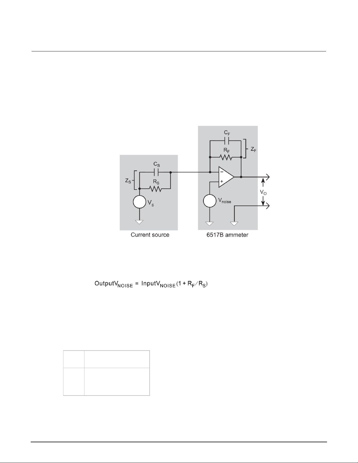
Section 4: Measurement considerations Model 6517B Electrometer Reference Manual
4-6 6517B-901-01 Rev. E August 2022
Source resistance
The source resistance of the device under test affects the noise performance of current
measurements. As the source resistance is reduced, the noise gain of the ammeter increases.
The following figure shows a simplified model of the feedback ammeter.
Figure 32: Source resistance and capacitance
RS and CS represent the source resistance and source capacitance, VS is the source voltage, and
V
NOISE
is the noise voltage. RF and CF are the feedback resistance and capacitance, respectively.
The source noise gain of the circuit can be given by the following equation:
As RS decreases in value, the output noise increases. For example, when RF = RS, the input noise is
multiplied by a factor of two. Since decreasing the source resistance can have a detrimental effect on
noise performance, there are usually minimum recommended source resistance values based on
measurement range. The following table summarizes minimum recommended source resistance
values for various measurement ranges. The recommended source resistance varies by
measurement range because the RF value also depends on the measurement range.
Range
Minimum recommended
source resistance
pA
nA
μA
mA
1 GΩ to 100 GΩ
1 MΩ to 100 MΩ
1 kΩ to 100 kΩ
1 Ω to 100 Ω
Page 80

Model 6517B Electrometer Reference Manual Section 4: Measurement considerations
6517B-901-01 Rev. E August 2022 4-7
Source capacitance
DUT source capacitance also affects the noise performance of the 6517B ammeter. In general, as
source capacitance increases, the noise also increases. To see how changes in source capacitance
can affect noise gain, refer to the simplified ammeter model in Source resistance (on page 4-6).
The elements of interest for this discussion are the source capacitance, CS, and the feedback
capacitance, CF. To take the capacitive reactance of these two elements into account, the previous
noise gain formula must be modified as follows:
Here, ZF represents the feedback impedance made up of CF and RF. ZS is the source impedance
formed by RS and CS. Furthermore:
and
As CS increases in value, ZS decreases in value, thereby increasing the noise gain. At the point where
ZS = ZF, the input noise is amplified by a factor of two.
The maximum value of source capacitance (CS) for the 6517B ammeter is 10,000 pF. You can,
however, usually measure at higher source capacitance values by inserting a resistor in series with
the ammeter input. Be aware that any series resistance increases the voltage burden by a factor of IIN
* R
SERIES
. For example, the range of resistance listed in the table of minimum recommended source
resistance values (see Source resistance (on page 4-6)) results in voltage burden values in the range
of 1 mV to 1 V. A useful alternative to a series resistor is a series diode, or two diodes in parallel
back-to-back. The diodes can be small-signal types and should be in a light-tight enclosure.
Guarding
For current measurements, guarding greatly reduces leakage currents in high-impedance test
circuits. The ammeter input LO (inner shield of the triaxial cable) is used as the guard.
For information on connections for guard and enabling guard, refer to “Shielding and guarding” in the
Model 6517B User's Manual.
Page 81

Section 4: Measurement considerations Model 6517B Electrometer Reference Manual
4-8 6517B-901-01 Rev. E August 2022
High impedance current measurements
Significant leakage could occur across a high impedance (≥1 GΩ) DUT through the insulators, as
shown in the following figure, where RL1 and RL2 represent the leakage resistance. So instead of
measuring the current (IR) through R (which is ≥1 GΩ), you are also measuring the leakage current
(IL). The current measured by the ammeter is IR + IL.
Figure 33: High impedance current measurements - unguarded
By connecting ammeter input LO to the metal mounting (guard) plate, as shown in the following
figure, the leakage current (IL) is shunted to ammeter input LO and is not measured by the ammeter.
The ammeter only measures IR.
Figure 34: High impedance current measurements - guarded
Page 82

Model 6517B Electrometer Reference Manual Section 4: Measurement considerations
6517B-901-01 Rev. E August 2022 4-9
Floating current measurements
Guarding uses a conductor at essentially the same potential as the sensitive input to drastically
reduce leakage currents in high impedance test circuits. No current can flow when there is a 0 V drop
across a leakage resistance.
For floating current measurements, ammeter input low is used as the guard since it totally surrounds
input high (through the input triaxial cable) and it is at nearly the same potential as input high. In
reality, the ammeter drops <1 mV and is known as the voltage burden.
The following figure shows an unguarded floating current measurement in a high impedance circuit.
The goal is to measure the current (IR) through resistor R. However, a leakage path (RL) exists from
ammeter input LO to test circuit common. Since the ammeter drops < 1 mV, approximately 10 V is
dropped by RL. The current through RL is approximately 10 nA (10 V/1 GΩ = 10 nA), so the current
that is measured by the 6517B is the sum of the two currents (I = IR + 10 nA). If IR is a low-level
current, the 10 nA leakage current corrupts the measurement.
Figure 35: Floating current measurements - unguarded
The following figure shows the guarded version of the same circuit. Notice that the only difference is
that the connections to the 6517B are reversed. Resistor RL now represents the leakage from
ammeter input HI to ammeter input LO, and resistor RG represents the leakage from ammeter input
LO (guard) to test circuit common. As previously mentioned, the ammeter drops < 1 mV. It then
follows that there is a < 1 mV drop across RL, so the current through RL is
< 1 pA (< 1 mV/1 GΩ = < 1 pA). The current that is measured by the 6517B is the sum of the two
currents (I = IR + < 1 A). The use of guarding reduced the leakage current from 10 nA to < 1 pA. The
10 nA leakage current (IG) from ammeter input LO to test circuit low still exists, but it is
inconsequential because it is not measured by the 6517B.
Page 83

Section 4: Measurement considerations Model 6517B Electrometer Reference Manual
4-10 6517B-901-01 Rev. E August 2022
Figure 36: Floating current measurements - guarded
Resistance measurement considerations
Some considerations for making accurate resistance and resistivity measurements are summarized in
the following paragraphs. High resistance measurements (above 1 MΩ) may exhibit problematic
background currents and can be improved by using the alternating polarity test sequence. Refer to
Alternating polarity resistance/resistivity test (on page 5-13) for more detail.
See Other measurement considerations (on page 4-12) for additional information.
For comprehensive information on precision measurements, refer to the Low Level Measurements
Handbook, which is available from tek.com.
Leakage resistance
Even though the source voltage, measure current (SVMI) method for resistance measurements
minimizes the effects of leakage resistance, there some cases where leakage can affect the
measurement. For example, test fixture leakage paths may appear in parallel with the device being
measured, introducing errors in the measurement. These errors can be minimized by using proper
insulating materials (such as Teflon) in test fixture terminals and by keeping them clean and
moisture free.
Leakage currents in the test fixture can be canceled by using relative offset on the current component
of the measurement.
Page 84

Model 6517B Electrometer Reference Manual Section 4: Measurement considerations
6517B-901-01 Rev. E August 2022 4-11
Voltage coefficient
The measured value of a high-megohm resistor often varies with the applied voltage. This variation in
resistance is known as the voltage coefficient, and is usually expressed in percent/volt or ppm/volt
values. To obtain consistent test results, these resistors should always be biased at the
same voltage.
You can use the 6517B to characterize these resistance changes by measuring the resistance with a
number of different applied voltages. Once the variations are known, the voltage coefficient of the
resistor being tested can be determined.
Test voltage and electrification time
The test voltages that are typically specified to be applied to the insulator sample are 100 V, 250 V,
and 1000 V. Higher test voltages are sometimes used, however, the maximum voltage that can be
applied to the Model 8009 is 1000 V, which is the maximum output of the 6517B voltage source.
Unless otherwise specified, the applied direct voltage to the insulator sample should be 500 V.
Electrification time, also known as bias time, is the total time that the specified voltage is applied to
the insulator sample when the measurement is made. For example, for an electrification time of
60 seconds, the measurement is made after the insulator sample is subjected to the applied test
voltage for 60 seconds. The conventional arbitrary electrification time is 60 seconds, but special
studies or experimentation may dictate a different electrification time.
Current measurement considerations
Resistance measurements are performed by sourcing voltage and measuring current, so accurate
measurements require accurate current measurements. Refer to Current measurement
considerations (on page 4-4) for more information.
Capacitive inputs increase preamplifier noise, resulting in increased noise across the voltage
source terminals.
Charge measurement considerations
Some considerations for making accurate charge measurements are summarized in the
following paragraphs.
See Other measurement considerations (on page 4-12) for additional information.
For comprehensive information on precision measurements, refer to the Low Level Measurements
Handbook, which is available from tek.com.
Page 85

Section 4: Measurement considerations Model 6517B Electrometer Reference Manual
4-12 6517B-901-01 Rev. E August 2022
Input bias current
A primary consideration when making charge measurements is the input bias (offset) current of the
integrating amplifier. Input bias current is integrated with the input signal and reflected in the final
reading. The maximum input bias for the charge function of the 6517B 4 fA (4 × 10
−15
A) at 23 °C.
This input offset translates into a charge of 4 fC per second at a temperature of 23 °C. This value
must be subtracted from the final reading to obtain the correct value.
You can reduce the input bias current by performing the offset adjustment procedure. Refer to
Relative offset (on page 3-29).
External voltage source
When using an external voltage source, the input current should be limited to less than 1 mA by
placing a resistor in series with the high input lead. The value of this resistor should be at least:
R = 1000 × V (ohms)
Where V is the voltage across the resistor or the compliance of the current being integrated.
Measurement times
Long measurement times may degrade charge measurement accuracy. See the 6517B
specifications, available at tek.com/keithley.
Zero check hop and autodischarge hop
Switching from the enabled to disabled state of the zero check feature causes a sudden change in
the charge reading, known as zero check hop. This sudden change in charge also occurs when the
autodischarge feature resets the charge reading to zero. To eliminate this hop in charge, enable the
relative offset immediately after zero check is disabled or when autodischarge resets the charge
reading. This action nulls out the charge reading caused by the hop.
You can also make a reading immediately when zero check is disabled or when an autodischarge
occurs and subtract that reading from all subsequent readings.
Other measurement considerations
The following measurement considerations apply to all precision measurements. For comprehensive
information on all measurement considerations, refer to the Low Level Measurements Handbook,
which is available from tek.com/keithley.
Page 86

Model 6517B Electrometer Reference Manual Section 4: Measurement considerations
6517B-901-01 Rev. E August 2022 4-13
Ground loops
Ground loops that occur in multiple-instrument test setups can create error signals that cause erratic
or erroneous measurements. The configuration shown in the following figure introduces errors in two
ways. Large ground currents flowing in one of the wires encounter small resistances, either in the
wires, or at the connecting points. This small resistance results in voltage drops that can affect the
measurement. Even if the ground loop currents are small, magnetic flux cutting across the large loops
formed by the ground leads can induce sufficient voltages to disturb sensitive measurements.
Figure 37: Power-line ground loops
To prevent ground loops, instruments should be connected to ground at a single point, as shown in
the following figure, where a single instrument is connected directly to power line ground.
Experimentation is the best way to determine an acceptable arrangement. For this purpose,
measuring instruments should be placed on their lowest ranges. The configuration that results in the
lowest noise signal is the one that should be used.
Figure 38: Eliminating ground loops
Page 87

Section 4: Measurement considerations Model 6517B Electrometer Reference Manual
4-14 6517B-901-01 Rev. E August 2022
Triboelectric effects
Triboelectric currents are generated by charges created between a conductor and an insulator due to
friction. Free electrons rub off the conductor and create a charge imbalance that causes the current
flow. For example, bending a triaxial cable causes friction between the center conductor (HI) and its
surrounding insulator, resulting in triboelectric currents.
To minimize triboelectric currents:
• Use low noise cables. These cables are designed to minimize charge generation and use
graphite to reduce friction. The Keithley Instruments Model 7078-TRX triaxial cables are
low noise.
• Use the shortest cables possible.
• Secure cables (for example, tape or tie) to a nonvibrating surface.
Piezoelectric and stored charge effects
Piezoelectric currents are generated when mechanical stress is applied to certain insulating
materials, such as crystalline. In some plastics, pockets of stored charge cause the material to
behave in a similar manner.
When building test fixtures, choose good insulating materials and make connecting structures as rigid
as possible. Make sure there are no mechanical stresses on the insulators.
Electrochemical effects
Error currents can arise from electrochemical effects when ionic chemicals create weak batteries on a
circuit board. These batteries can generate a few nanoamps of current between conductors. Ionic
contamination may be the result of body oils, salts, or solder flux. The problem is further enhanced by
high humidity (moisture) that decreases insulation resistance.
When building test fixtures, select insulators that resist water absorption and use the fixture in a
moderate humidity environment. Keep all insulators clean and free of contamination.
Humidity
Excess humidity can reduce insulation resistance on printed circuit boards and in test connection
insulators. Reduction in insulation resistance can seriously affect high-impedance measurements.
Moisture can combine with contaminants to produce offset currents caused by electrochemical
effects. To minimize the effects of moisture, keep humidity to a minimum (ideally < 50 percent), and
keep components and connectors in the test system clean.
Page 88

Model 6517B Electrometer Reference Manual Section 4: Measurement considerations
6517B-901-01 Rev. E August 2022 4-15
Light
Some components, such as semiconductor junctions and MOS capacitors on semiconductor wafers,
are excellent light detectors. Consequently, these components must be tested in a light-free
environment. Many test fixtures provide adequate light protection, but others may allow enough light
penetration to affect the test results. Areas to check for light leaks include doors and door hinges,
tubing entry points, and connectors or connector panels.
Electrostatic interference
Electrostatic interference occurs when an electrically charged object is brought near an uncharged
object, inducing a charge on the previously uncharged object. Usually, effects of such electrostatic
action are not noticeable because low impedance levels allow the induced charge to dissipate
quickly. However, the high impedance levels of many 6517B measurements do not allow these
charges to decay rapidly, which may result in erroneous or unstable readings. These erroneous or
unstable readings may be caused in the following ways:
• DC electrostatic field can cause undetected errors or noise in the reading.
• AC electrostatic fields can cause errors by driving the input preamplifier into saturation or through
rectification that produces dc errors.
Electrostatic interference is first recognizable when hand or body movements near the experiment
cause fluctuations in the reading. Pick-up from ac fields can also be detected by observing the 6517B
preamplifier output on an oscilloscope. Line frequency signals on the output are an indication that
electrostatic interference is present.
To minimize electrostatic interference:
• Use shielding. Possibilities include a shielded room, a shielded booth, shielding the sensitive
circuit, and using shielded cable. Refer to “Shielding and guarding” in the Model 6517B User's
Manual for detail.
• Reduce electrostatic fields. Move power lines or other sources away from the device under test.
Magnetic fields
A magnetic field passing through a loop in a test circuit generates a magnetic EMF (voltage) that is
proportional to the strength of the field, the loop area, and the rate at which these factors
are changing.
To minimize magnetic fields:
• Locate the test circuit as far away as possible from magnetic field sources such as motors,
transformers, and magnets.
• Avoid moving any part of the test circuit within the magnetic field.
• Minimize the loop area by keeping leads as short as possible and twisting them together.
Page 89

Section 4: Measurement considerations Model 6517B Electrometer Reference Manual
4-16 6517B-901-01 Rev. E August 2022
Electromagnetic interference
The electromagnetic interference (EMI) characteristics of the 6517B comply with the electromagnetic
compatibility (EMC) requirements of the European Union as denoted by the CE mark. However, it is
still possible for sensitive measurements to be affected by external sources. In these instances,
special precautions may be required in the measurement setup.
Sources of EMI include:
• Radio and TV broadcast transmitters.
• Communications transmitters, including mobile phones and handheld radios.
• Devices incorporating microprocessors and high-speed digital circuits.
• Impulse sources, such as arcing in high-voltage environments.
The effect of EMI on instrument performance can be considerable if enough of the unwanted signal is
present. The effects of EMI can be seen as an unusually large offset. If the EMI is from impulse
sources, there will be erratic variations in the displayed reading.
To avoid the effects of EMI, keep the instrument and experiment as far away as possible from any
EMI sources. Additional shielding of the instrument, experiment, and test leads often reduces EMI to
an acceptable level. In extreme cases, a specially constructed screen room may be required to
sufficiently attenuate the troublesome signal.
External filtering of the input signal path may be required. In some cases, a simple one-pole filter may
be sufficient. In more difficult situations, multiple notch or band-stop filters, tuned to the EMI
frequency range, may be required. Connecting multiple capacitors of widely different values in parallel
maintains a low impedance across a wide frequency range. Be aware that filtering may have
detrimental effects (such as increased response time) on the measurement.
Page 90

In this section:
Introduction ...............................................................................5-1
Diode leakage current test ........................................................5-2
Capacitor leakage current test ..................................................5-5
Cable insulation resistance test ................................................5-7
Resistor voltage coefficient test ................................................5-9
Standard method resistivity tests ............................................5-11
Alternating polarity resistance/resistivity test...........................5-13
Surface insulation resistance (SIR) test ..................................5-16
Square wave sweep test .........................................................5-19
Staircase sweep test ...............................................................5-20
Configure sequence menu ......................................................5-22
Introduction
The 6517B has the following built-in test sequences:
• Device characterization tests:
▪ Diode leakage current
▪ Capacitor leakage
▪ Cable insulation resistance
▪ Resistor voltage coefficient
• Resistivity tests:
▪ Normal (surface and volume)
▪ Alternating polarity
• Surface insulation resistance (SIR) test
• Sweep tests:
▪ Square wave
▪ Staircase
The following information describes each test, shows the connections to the 6517B, and explains how
to set up the 6517B for the measurements.
The results of a test are stored in the buffer. For example, if a test performs 10 measurements, those
10 readings are stored in the buffer at locations 0 through 9. If a test only performs one
measurement, that single reading is stored at memory location 0. When a test is performed, previous
data stored in the buffer is cleared.
Section 5
Test sequences
Page 91

Section 5: Test sequences Model 6517B Electrometer Reference Manual
5-2 6517B-901-01 Rev. E August 2022
Diode leakage current test
This test measures the leakage current for a diode and allows you to measure the current at various
voltage levels.
The following figure shows an example using the default test parameters. When the test is run, 10
current measurements are made (one at each voltage step) and stored in the buffer.
Figure 39: Diode leakage current test default measurement points
Test parameters:
• START V: +1 V
• STOP V: +10 V
• STEP V: +1 V
• DELAY: 1 s
Page 92

Model 6517B Electrometer Reference Manual Section 5: Test sequences
6517B-901-01 Rev. E August 2022 5-3
Diode leakage current test connections
The following figure shows the connections and the simplified schematic for this test.
Figure 40: Diode leakage current test connections
Ammeter LO is internally connected to V-SOURCE LO.
Figure 41: Diode leakage current test equivalent circuit
This test sources a positive voltage to measure the leakage current through the diode. If you source a
negative voltage, you forward bias the diode. Resistor R limits the current if the diode shorts out or
becomes forward biased. Select a value of R that limits current to 20 mA or less.
Page 93

Section 5: Test sequences Model 6517B Electrometer Reference Manual
5-4 6517B-901-01 Rev. E August 2022
Run the diode leakage current test
To run the diode leakage current test:
1. Press the Z-CHK key to enable zero check.
2. Make sure the voltage source is in standby (VOLTAGE SOURCE OPERATE LED off).
3. Press the CONFIG key.
4. Press the SEQ key.
5. Select APPLICATIONS. Press the ENTER key.
6. Select DEV-CHAR. Press the ENTER key.
7. Select DIODE. Press the ENTER key.
8. Select LEAKAGE-CURRENT. Press the ENTER key.
9. Set the following parameters. Press the ENTER key after each setting to advance to the next
menu item.
▪ START V: The start voltage.
▪ STOP V: The stop voltage.
▪ STEP V: The step voltage.
▪ DELAY: The delay in seconds.
10. Press the EXIT key to return to the CONFIGURE SEQUENCE menu.
11. Select CONTROL. Press the ENTER key.
12. Set the event that triggers the test to start:
▪ MANUAL: Start when the TRIG key is pressed.
▪ IMMEDIATE: Start as soon as the test is armed.
▪ LID-CLOSURE: Start when the test fixture lid is closed.
▪ GPIB: Start on GPIB trigger (GET or *TRG) or when the TRIG key is pressed.
▪ EXTERNAL: Start when an external trigger is received or when the TRIG key is pressed.
▪ TRIGLINK: Start when a trigger is received through the specified trigger-link line or when the
TRIG key is pressed.
13. Press the ENTER key.
14. Press the EXIT key to return to the measurement display.
15. Press the SEQ key to arm the test. When the selected trigger source event occurs, zero check is
disabled and the test runs. SEQ flashes on the display while the test is running. Readings are
automatically stored in the buffer starting at memory location zero.
16. When the test is finished, zero check remains disabled and the voltage source goes into standby.
17. To access the measured readings, press the RECALL key.
Page 94

Model 6517B Electrometer Reference Manual Section 5: Test sequences
6517B-901-01 Rev. E August 2022 5-5
Capacitor leakage current test
This test measures the leakage current of a capacitor. The magnitude of the leakage depends on the
type of dielectric and the applied voltage.
For this test, a fixed voltage (BIAS V) is applied to the capacitor for specified time intervals to allow
the capacitor to charge (current decays exponentially with time). The leakage current is measured at
each interval and stored in the buffer.
Capacitor leakage current test connections
The following figure shows the connections for this test. The resistor and diode limit noise for the
measurement.
Figure 42: Capacitor leakage current test connections
Ammeter LO is internally connected to V-SOURCE LO.
Figure 43: Capacitor leakage current test connections - equivalent circuit
Page 95

Section 5: Test sequences Model 6517B Electrometer Reference Manual
5-6 6517B-901-01 Rev. E August 2022
Run the capacitor leakage current test
To run the capacitor leakage current test:
1. Press the Z-CHK key to enable zero check.
2. Make sure the voltage source is in standby (VOLTAGE SOURCE OPERATE LED off).
3. Press the CONFIG key.
4. Press the SEQ key.
5. Select DEV-CHAR. Press the ENTER key.
6. Select CAPACITOR. Press the ENTER key.
7. Select LEAKAGE-CURRENT. Press the ENTER key.
8. Set the following parameters. Press the ENTER key after each setting to advance to the next
menu item.
▪ BIAS V: The bias voltage.
▪ STORE nnnnn READINGS: The number of readings to make.
▪ INTERVAL: The interval between readings in seconds.
9. Press the EXIT key to return to the previous menu.
10. Set the event that triggers the test to start:
▪ MANUAL: Start when the TRIG key is pressed.
▪ IMMEDIATE: Start as soon as the test is armed.
▪ LID-CLOSURE: Start when the test fixture lid is closed.
▪ GPIB: Start on GPIB trigger (GET or *TRG) or when the TRIG key is pressed.
▪ EXTERNAL: Start when an external trigger is received or when the TRIG key is pressed.
▪ TRIGLINK: Start when a trigger is received through the specified trigger-link line or when the
TRIG key is pressed.
11. Press the ENTER key.
12. Press the EXIT key to return to the measurement display.
13. Press the SEQ key to arm the test. When the selected trigger source event occurs, zero check is
disabled and the test runs. SEQ flashes on the display while the test is running. Readings are
automatically stored in the buffer starting at memory location zero.
14. Press ENTER to arm the test. When the selected trigger source event occurs, zero check is
disabled and the test runs.
15. When the test is finished, zero check remains disabled and the voltage source goes into standby.
16. To access the measured readings, press the RECALL key.
Page 96

Model 6517B Electrometer Reference Manual Section 5: Test sequences
6517B-901-01 Rev. E August 2022 5-7
Cable insulation resistance test
The test measures the resistance of the insulator of a cable between the shield and the
inner conductor.
Cable insulation resistance test connections
The following figure shows the connections for this test.
Keep the cable sample as short as possible to minimize input capacitance to the ammeter.
Figure 44: Cable insulation resistance test connections
Ammeter LO is internally connected to V-SOURCE LO.
Figure 45: Cable insulation resistance test connections - equivalent circuit
Page 97

Section 5: Test sequences Model 6517B Electrometer Reference Manual
5-8 6517B-901-01 Rev. E August 2022
Run the cable insulation resistance test
To run the cable insulation resistance test:
1. Press the Z-CHK key to enable zero check.
2. Make sure the voltage source is in standby (VOLTAGE SOURCE OPERATE LED off).
3. Press the CONFIG key.
4. Press the SEQ key.
5. Select DEV-CHAR. Press the ENTER key.
6. Select CABLE. Press the ENTER key.
7. Select INSULATION-RESISTANCE. Press the ENTER key.
8. Set the following parameters. Press the ENTER key after each setting to advance to the next
menu item.
▪ BIAS V: The bias voltage. The bias voltage is applied across the insulator for a specified time
to allow the charging effects of cable capacitance to stabilize.
▪ STORE READINGS: The number of readings to make.
▪ INTERVAL: The interval between readings in seconds.
9. Press the EXIT key to return to the previous menu.
10. Set the event that triggers the test to start:
▪ MANUAL: Start when the TRIG key is pressed.
▪ IMMEDIATE: Start as soon as the test is armed.
▪ LID-CLOSURE: Start when the test fixture lid is closed.
▪ GPIB: Start on GPIB trigger (GET or *TRG) or when the TRIG key is pressed.
▪ EXTERNAL: Start when an external trigger is received or when the TRIG key is pressed.
▪ TRIGLINK: Start when a trigger is received through the specified trigger-link line or when the
TRIG key is pressed.
11. Press the ENTER key.
12. Press the EXIT key to return to the measurement display.
13. Press the SEQ key to arm the test. When the selected trigger source event occurs, zero check is
disabled and the test runs. SEQ flashes on the display while the test is running. Readings are
automatically stored in the buffer starting at memory location zero.
14. Press ENTER to arm the test. When the selected trigger source event occurs, zero check is
disabled and the test runs.
15. When the test is finished, zero check remains disabled and the voltage source goes into standby.
16. To access the measured readings, press the RECALL key.
Page 98

Model 6517B Electrometer Reference Manual Section 5: Test sequences
6517B-901-01 Rev. E August 2022 5-9
Resistor voltage coefficient test
High valued resistors often have a change in resistance with applied voltage. This change in
resistance is characterized as the voltage coefficient. Voltage coefficient is defined as the percent
change in resistance per unit change in applied voltage:
This test makes two resistance measurements at two different voltage levels and calculates the
voltage coefficient.
Resistor voltage coefficient test connections
The test circuit is shown in the following figure. The resistor should be placed in a shielded test fixture
that is designed to minimize leakage resistance.
Figure 46: Resistor voltage coefficient test circuit
Ammeter LO is internally connected to V-SOURCE LO.
Page 99

Section 5: Test sequences Model 6517B Electrometer Reference Manual
5-10 6517B-901-01 Rev. E August 2022
Run the resistor voltage coefficient test
To run the resistor voltage coefficient test:
1. Press the Z-CHK key to enable zero check.
2. Make sure the voltage source is in standby (VOLTAGE SOURCE OPERATE LED off).
3. Press the CONFIG key.
4. Press the SEQ key.
5. Select DEV-CHAR. Press the ENTER key.
6. Select RESISTOR. Press the ENTER key.
7. Select VOLTAGE-COEFFICIENT. Press the ENTER key.
8. Set the following parameters. Press the ENTER key after each setting to advance to the next
menu item.
▪ SOURCE V1: The first test voltage.
▪ DELAY 1: The first delay in seconds.
▪ SOURCE V2: The second test voltage.
▪ DELAY 2: The second delay in seconds.
9. Press the EXIT key to return to the previous menu.
10. Set the event that triggers the test to start:
▪ MANUAL: Start when the TRIG key is pressed.
▪ IMMEDIATE: Start as soon as the test is armed.
▪ LID-CLOSURE: Start when the test fixture lid is closed.
▪ GPIB: Start on GPIB trigger (GET or *TRG) or when the TRIG key is pressed.
▪ EXTERNAL: Start when an external trigger is received or when the TRIG key is pressed.
▪ TRIGLINK: Start when a trigger is received through the specified trigger-link line or when the
TRIG key is pressed.
11. Press the ENTER key.
12. Press the EXIT key to return to the measurement display.
13. Press the SEQ key to arm the test. When the selected trigger source event occurs, zero check is
disabled and the test runs. SEQ flashes on the display while the test is running. Readings are
automatically stored in the buffer starting at memory location zero.
14. Press ENTER to arm the test. When the selected trigger source event occurs, zero check is
disabled and the test runs. SOURCE V1 is applied to the resistor. After DELAY 1, a resistance
measurement is made. SOURCE V2 is then applied. After DELAY 2, a second resistance
measurement is made. The 6517B then automatically calculates the voltage coefficient and
stores it in the buffer.
15. When the test is finished, zero check remains disabled and the voltage source goes into standby.
16. To access the measured readings, press the RECALL key.
Page 100

Model 6517B Electrometer Reference Manual Section 5: Test sequences
6517B-901-01 Rev. E August 2022 5-11
Standard method resistivity tests
This test measures the resistivity (surface or volume) of an insulator sample. When used with the
Keithley Instruments Model 8009 Resistivity Test Fixture, the test conforms to the
ASTM D-257 standard.
Resistivity test connections
Refer to the following figure for connections to the Model 8009 for these tests. Refer to the instruction
manual for the Model 8009 to install the insulator sample in the test fixture.
If the 6517B is configured to use the Model 8009 Resistivity Test Fixture, the interlock cable must be
connected to the 8009 test fixture. The measurement type (surface or volume) is automatically
selected by the switch position on the test fixture. Attempts to change the measurement type from
the 6517B menu are ignored. If the interlock cable is not connected, the settings for volume or
surface do not work properly.
Hazardous voltages may be present on the output and guard terminals. To prevent electrical
shock that could cause injury or death, NEVER make or break connections to the 6517B while
the output is on. Power off the equipment from the front panel or disconnect the main power
cord from the rear of the 6517B before handling cables connected to the outputs. Putting the
equipment in standby mode does not guarantee that the outputs are not powered if a
hardware or software fault occurs.
Connect earth ground of the test fixture to protective earth (safety ground) using safety
ground wire.
 Loading...