

Page 1

www.keithley.com
Model 6487 Picoammeter/Voltage Source
Reference Manual
6487-901-01 Rev. D October 2020
*P648790101D*
6487-901-01
A Greater Measure of Confidence
Page 2

Model 6487 Picoammeter / Voltage Source
Reference Manual
Page 3

© 2020, Keithley Instruments, LLC
Cleveland, Ohio, U.S.A.
All rights reserved.
Any unauthorized reproduction, photocopy, or use of the information herein, in whole or in part,
without the prior written approval of Keithley Instruments, LLC, is strictly prohibited.
These are the original instructions in English.
All Keithley Instruments product names are trademarks or registered trademarks of Keithley
Instruments, LLC. Other brand names are trademarks or registered trademarks of their respective
holders.
Microsoft, Visual C++, Excel, and Windows are either registered trademarks or trademarks of
Microsoft Corporation in the United States and/or other countries.
Document number: 6487-901-01 Rev. D October 2020
Page 4

Safety precautions
The following safety precautions should be observed before using this product and any associated instrumentation. Although
some instruments and accessories would normally be used with nonhazardous voltages, there are situations where hazardous
conditions may be present.
This product is intended for use by personnel who recognize shock hazards and are familiar with the safety precautions required
to avoid possible injury. Read and follow all installation, operation, and maintenance information carefully before using the
product. Refer to the user documentation for complete product specifications.
If the product is used in a manner not specified, the protection provided by the product warranty may be impaired.
The types of product users are:
Responsible body is the individual or group responsible for the use and maintenance of equipment, for ensuring that the
equipment is operated within its specifications and operating limits, and for ensuring that operators are adequately trained.
Operators use the product for its intended function. They must be trained in electrical safety procedures and proper use of the
instrument. They must be protected from electric shock and contact with hazardous live circuits.
Maintenance personnel perform routine procedures on the product to keep it operating properly, for example, setting the line
voltage or replacing consumable materials. Maintenance procedures are described in the user documentation. The procedures
explicitly state if the operator may perform them. Otherwise, they should be performed only by service personnel.
Service personnel are trained to work on live circuits, perform safe installations, and repair products. Only properly trained
service personnel may perform installation and service procedures.
Keithley products are designed for use with electrical signals that are measurement, control, and data I/O connections, with low
transient overvoltages, and must not be directly connected to mains voltage or to voltage sources with high transient
overvoltages. Measurement Category II (as referenced in IEC 60664) connections require protection for high transient
overvoltages often associated with local AC mains connections. Certain Keithley measuring instruments may be connected to
mains. These instruments will be marked as category II or higher.
Unless explicitly allowed in the specifications, operating manual, and instrument labels, do not connect any instrument to mains.
Exercise extreme caution when a shock hazard is present. Lethal voltage may be present on cable connector jacks or test
fixtures. The American National Standards Institute (ANSI) states that a shock hazard exists when voltage levels greater than
30 V RMS, 42.4 V peak, or 60 VDC are present. A good safety practice is to expect that hazardous voltage is present in any
unknown circuit before measuring.
Operators of this product must be protected from electric shock at all times. The responsible body must ensure that operators
are prevented access and/or insulated from every connection point. In some cases, connections must be exposed to potential
human contact. Product operators in these circumstances must be trained to protect themselves from the risk of electric shock. If
the circuit is capable of operating at or above 1000 V, no conductive part of the circuit may be exposed.
Do not connect switching cards directly to unlimited power circuits. They are intended to be used with impedance-limited
sources. NEVER connect switching cards directly to AC mains. When connecting sources to switching cards, install protective
devices to limit fault current and voltage to the card.
Before operating an instrument, ensure that the line cord is connected to a properly-grounded power receptacle. Inspect the
connecting cables, test leads, and jumpers for possible wear, cracks, or breaks before each use.
When installing equipment where access to the main power cord is restricted, such as rack mounting, a separate main input
power disconnect device must be provided in close proximity to the equipment and within easy reach of the operator.
For maximum safety, do not touch the product, test cables, or any other instruments while power is applied to the circuit under
test. ALWAYS remove power from the entire test system and discharge any capacitors before: connecting or disconnecting
cables or jumpers, installing or removing switching cards, or making internal changes, such as installing or removing jumpers.
Do not touch any object that could provide a current path to the common side of the circuit under test or power line (earth)
ground. Always make measurements with dry hands while standing on a dry, insulated surface capable of withstanding the
voltage being measured.
Page 5

For safety, instruments and accessories must be used in accordance with the operating instructions. If the instruments or
accessories are used in a manner not specified in the operating instructions, the protection provided by the equipment may be
impaired.
Do not exceed the maximum signal levels of the instruments and accessories. Maximum signal levels are defined in the
specifications and operating information and shown on the instrument panels, test fixture panels, and switching cards.
When fuses are used in a product, replace with the same type and rating for continued protection against fire hazard.
Chassis connections must only be used as shield connections for measuring circuits, NOT as protective earth (safety ground)
connections.
If you are using a test fixture, keep the lid closed while power is applied to the device under test. Safe operation requires the use
of a lid interlock.
If a screw is present, connect it to protective earth (safety ground) using the wire recommended in the user documentation.
The symbol on an instrument means caution, risk of hazard. The user must refer to the operating instructions located in the
user documentation in all cases where the symbol is marked on the instrument.
The symbol on an instrument means warning, risk of electric shock. Use standard safety precautions to avoid personal
contact with these voltages.
The symbol on an instrument shows that the surface may be hot. Avoid personal contact to prevent burns.
The symbol indicates a connection terminal to the equipment frame.
If this symbol is on a product, it indicates that mercury is present in the display lamp. Please note that the lamp must be
properly disposed of according to federal, state, and local laws.
The WARNING heading in the user documentation explains hazards that might result in personal injury or death. Always read
the associated information very carefully before performing the indicated procedure.
The CAUTION heading in the user documentation explains hazards that could damage the instrument. Such damage may
invalidate the warranty.
The CAUTION heading with the symbol in the user documentation explains hazards that could result in moderate or minor
injury or damage the instrument. Always read the associated information very carefully before performing the indicated
procedure. Damage to the instrument may invalidate the warranty.
Instrumentation and accessories shall not be connected to humans.
Before performing any maintenance, disconnect the line cord and all test cables.
To maintain protection from electric shock and fire, replacement components in mains circuits — including the power
transformer, test leads, and input jacks — must be purchased from Keithley. Standard fuses with applicable national safety
approvals may be used if the rating and type are the same. The detachable mains power cord provided with the instrument may
only be replaced with a similarly rated power cord. Other components that are not safety-related may be purchased from other
suppliers as long as they are equivalent to the original component (note that selected parts should be purchased only through
Keithley to maintain accuracy and functionality of the product). If you are unsure about the applicability of a replacement
component, call a Keithley office for information.
Unless otherwise noted in product-specific literature, Keithley instruments are designed to operate indoors only, in the following
environment: Altitude at or below 2,000 m (6,562 ft); temperature 0 °C to 50 °C (32 °F to 122 °F); and pollution degree 1 or 2.
To clean an instrument, use a cloth dampened with deionized water or mild, water-based cleaner. Clean the exterior of the
instrument only. Do not apply cleaner directly to the instrument or allow liquids to enter or spill on the instrument. Products that
consist of a circuit board with no case or chassis (e.g., a data acquisition board for installation into a computer) should never
require cleaning if handled according to instructions. If the board becomes contaminated and operation is affected, the board
should be returned to the factory for proper cleaning/servicing.
Safety precaution revision as of June 2017.
Page 6

Introduction .............................................................................................................. 1-1
Welcome .............................................................................................................................. 1-1
Extended warranty ............................................................................................................... 1-1
Contact information .............................................................................................................. 1-1
General information .............................................................................................................. 1-2
Unpacking and inspection ................................................................ ......................................... 1-2
Package contents ...................................................................................................................... 1-2
Additional references ................................................................................................................ 1-3
Power-up .............................................................................................................................. 1-3
Line power connection .............................................................................................................. 1-3
Line frequency ........................................................................................................................... 1-4
Power-up sequence .................................................................................................................. 1-6
Front panel operation ........................................................................................................... 1-7
Status and error messages .................................................................................................. 1-7
Default settings .................................................................................................................... 1-8
Front panel setup operation ...................................................................................................... 1-8
Remote setup operation ............................................................................................................ 1-9
Menus................................................................................................................................. 1-11
Main menus............................................................................................................................. 1-11
Configuration menus ............................................................................................................... 1-12
SCPI programming ............................................................................................................. 1-13
Optional command words........................................................................................................ 1-13
Query commands .................................................................................................................... 1-13
Measurement concepts and connections .............................................................. 2-1
Connection fundamentals .................................................................................................... 2-1
Input connector ......................................................................................................................... 2-1
Voltage source output connectors ............................................................................................. 2-1
Maximum input levels ................................................................................................................ 2-2
Low-noise input cables .............................................................................................................. 2-2
Voltage source test leads .......................................................................................................... 2-3
Basic connections to the DUT .............................................................................................. 2-3
Current measurement connections ........................................................................................... 2-4
Ohms measurement connections .............................................................................................. 2-4
Voltage source connections ...................................................................................................... 2-5
Voltages greater than 505 V...................................................................................................... 2-6
Noise and safety shields ........................................................................................................... 2-7
Using a test fixture ............................................................................................................... 2-8
General purpose test fixture ...................................................................................................... 2-8
Model 8009 resistivity test fixture ............................................................................................ 2-11
Floating measurements ........................................................................................................... 2-12
Interlock .............................................................................................................................. 2-13
Interlock connections .............................................................................................................. 2-14
Interlock operation ................................................................................................................... 2-14
Interlock programming ............................................................................................................ 2-15
Analog output ..................................................................................................................... 2-15
Table of contents
Page 7

Table of contents Model 6487 Picoammeter / Voltage Source Reference Manual
Measurement considerations ............................................................................................. 2-17
Measurement and sourcing voltage ....................................................................... 3-1
Measurement overview ........................................................................................................ 3-1
Current measurements ............................................................................................................. 3-1
Voltage source .......................................................................................................................... 3-1
Performance considerations ................................................................................................ 3-2
Warm-up period ........................................................................................................................ 3-2
Voltage offset correction ........................................................................................................... 3-2
Autozero .................................................................................................................................... 3-3
Zero check and zero correct...................................................................................................... 3-4
Current measurements ........................................................................................................ 3-8
Procedure.................................................................................................................................. 3-8
SCPI programming - current measurements ........................................................................... 3-11
Programming example - current measurements ..................................................................... 3-12
Ohms measurements ......................................................................................................... 3-12
Overview ................................ ................................................................ ................................. 3-12
Procedure................................................................................................................................ 3-13
SCPI programming - ohms measurements ............................................................................. 3-16
Programming example - ohms measurements........................................................................ 3-17
Voltage source operation ................................................................................................... 3-17
Voltage source edit keys ......................................................................................................... 3-17
Configuring the voltage source ................................................................................................ 3-18
Sourcing voltage ..................................................................................................................... 3-18
Operate considerations ........................................................................................................... 3-20
Compliance indication ............................................................................................................. 3-21
Open interlock indication ......................................................................................................... 3-21
SCPI commands - voltage source ........................................................................................... 3-22
Programming example — voltage ........................................................................................... 3-23
Alternating voltage ohms mode ......................................................................................... 3-24
Overview ................................ ................................................................ ................................. 3-24
Storing A-V ohms readings ..................................................................................................... 3-26
Recalling A-V ohms readings .................................................................................................. 3-31
Operating considerations ........................................................................................................ 3-32
SCPI commands — A-V ohms ................................................................................................ 3-35
Programming example — A-V ohms measurements .............................................................. 3-39
Range, units, digits, rate, and filters ....................................................................... 4-1
Range, units, and digits........................................................................................................ 4-1
Range ....................................................................................................................................... 4-1
Units .......................................................................................................................................... 4-3
Digits ......................................................................................................................................... 4-3
SCPI programming for range and digits .................................................................................... 4-4
Rate ...................................................................................................................................... 4-5
SCPI programming — rate ........................................................................................................ 4-6
Programming example - rate ..................................................................................................... 4-6
Damping ............................................................................................................................... 4-6
Filters.................................................................................................................................... 4-7
Median filter............................................................................................................................... 4-8
Median filter control ................................................................................................................... 4-8
Page 8

Model 6487 Picoammeter / Voltage Source Reference Manual Table of contents
Digital filter ................................................................................................................................ 4-8
SCPI programming — filters.................................................................................................... 4-10
Programming example - rate ................................................................................................... 4-10
Relative, mX+b, m/X+b, and log .............................................................................. 5-1
Relative ................................................................................................................................ 5-1
Setting and controlling relative .................................................................................................. 5-1
SCPI programming — relative ................................................................................................... 5-3
mX+b, m/X+b (reciprocal), and logarithmic.......................................................................... 5-4
mX+b and m/X+b ...................................................................................................................... 5-4
Configuring and controlling mX+b and m/X+b ........................................................................... 5-5
Logarithmic................................................................................................................................ 5-6
SCPI programming — mX+b, m/X+b, and log........................................................................... 5-7
Buffer and sweeps ................................................................................................... 6-1
Store ..................................................................................................................................... 6-1
Buffer operations .................................................................................................................. 6-2
Recall ................................................................................................................................... 6-2
Buffer timestamps ................................................................................................................ 6-3
Buffer statistics ..................................................................................................................... 6-4
SCPI programming ............................................................................................................... 6-5
:TRACe:FREE? ......................................................................................................................... 6-6
:TRACe:FEED <name> ............................................................................................................. 6-6
:TRACe:FEED:CONTrol <name> .............................................................................................. 6-6
:TRACe:TSTamp:FORMat <name> .......................................................................................... 6-6
:TRACe:DATA? ......................................................................................................................... 6-7
:FORMat:ELEMents <list>......................................................................................................... 6-7
:CALCulate3:FORMat <name> ................................................................................................. 6-7
:CALCulate3:DATA? ................................................................................................................. 6-8
Programming example ......................................................................................................... 6-8
Voltage sweeps .................................................................................................................... 6-8
Overview ................................ ................................................................ ................................... 6-9
Sweep operation ..................................................................................................................... 6-10
Recalling sweep data .............................................................................................................. 6-10
Operating considerations ........................................................................................................ 6-11
Sweep example ....................................................................................................................... 6-12
SCPI programming — sweeps ................................................................................................ 6-12
Programming example ............................................................................................................ 6-15
Triggering ................................................................................................................. 7-1
Trigger models ..................................................................................................................... 7-1
Idle, initiate, and operation ................................................................ ........................................ 7-4
Event detectors and control sources ......................................................................................... 7-5
Trigger delay ............................................................................................................................. 7-6
Measure action .......................................................................................................................... 7-6
Output triggers .......................................................................................................................... 7-6
Counters.................................................................................................................................... 7-7
Trigger model configuration — front panel ................................................................................ 7-7
SCPI programming ............................................................................................................... 7-9
Page 9

Table of contents Model 6487 Picoammeter / Voltage Source Reference Manual
ABORt ..................................................................................................................................... 7-10
INITiate, FETCh, and READ? ................................................................................................. 7-10
ARM:SOURce <name> ........................................................................................................... 7-10
ARM:DIRection <name> ......................................................................................................... 7-10
ARM:ILINe <NRf> and ARM:OLINe <NRf> ............................................................................. 7-10
TRIGger:CLEar ....................................................................................................................... 7-10
Programming example ............................................................................................................ 7-11
External triggering .............................................................................................................. 7-11
Input trigger requirements ................................................................ ....................................... 7-12
Output trigger specifications .................................................................................................... 7-12
External trigger example ......................................................................................................... 7-13
Limit tests and digital I/O ......................................................................................... 8-1
Limit testing .......................................................................................................................... 8-1
Binning ................................................................................................................................. 8-4
Component handler interface .................................................................................................... 8-6
Component handler types ................................................................ ......................................... 8-7
Digital output clear pattern ........................................................................................................ 8-8
Digital I/O port .................................................................................................................... 8-10
Sink mode — controlling external devices .............................................................................. 8-12
Source mode — logic control .................................................................................................. 8-14
Setting digital output lines ....................................................................................................... 8-15
SCPI programming — digital output pattern ............................................................................ 8-15
Front panel operation — limit tests .................................................................................... 8-16
Limit test configuration ............................................................................................................ 8-16
Performing limit tests .......................................................................................................... 8-17
Step 1. Configure test system ................................................................................................. 8-17
Step 2. Configure measurement ............................................................................................. 8-17
Step 3. Configure limit tests .................................................................................................... 8-17
Step 4. Start testing process ................................................................................................... 8-17
SCPI programming — limit tests ........................................................................................ 8-18
:FEED <name> ....................................................................................................................... 8-19
<NDN> and <NRf> parameters ............................................................................................... 8-19
:FAIL? ..................................................................................................................................... 8-20
:DATA? and :DATA:LATest? ................................................................................................... 8-21
:ARM:SOURce <name> .......................................................................................................... 8-21
Programming example ............................................................................................................ 8-22
Remote operation ..................................................................................................... 9-1
Selecting and configuring an interface ................................................................................. 9-1
Interfaces .................................................................................................................................. 9-1
Languages ................................................................................................................................ 9-2
Interface selection and configuration ......................................................................................... 9-2
GPIB operation and reference................................................................................................... 9-4
RS-232 interface reference ................................................................................................ 9-16
Sending and receiving data ..................................................................................................... 9-16
RS-232 settings ....................................................................................................................... 9-16
RS-232 connections ................................................................................................................ 9-18
Error messages ....................................................................................................................... 9-19
Page 10

Model 6487 Picoammeter / Voltage Source Reference Manual Table of contents
Status structure...................................................................................................... 10-1
Overview ............................................................................................................................ 10-1
Clearing registers and queues ................................................................................................ 10-3
Programming and reading registers ................................................................................... 10-4
Programming enable registers ................................................................................................ 10-4
Reading registers .................................................................................................................... 10-5
Status byte and service request (SRQ) ............................................................................. 10-6
Status byte register ................................................................................................................. 10-7
Service request enable register ............................................................................................... 10-8
Serial polling and SRQ ............................................................................................................ 10-8
Status byte and service request commands............................................................................ 10-9
Programming example — set MSS (B6) when error occurs .................................................... 10-9
Status register sets .......................................................................................................... 10-10
Register bit descriptions ........................................................................................................ 10-10
Queues ............................................................................................................................. 10-17
Output queue ........................................................................................................................ 10-17
Error queue ........................................................................................................................... 10-18
Programming example — read error queue .......................................................................... 10-19
Common commands .............................................................................................. 11-1
Common commands .......................................................................................................... 11-1
IDN? ........................................................................................................................................ 11-2
OPC and OPC? ....................................................................................................................... 11-2
SAV <NRf> and RCL <NRf> ................................................................................................... 11-3
RST ......................................................................................................................................... 11-3
TST? ....................................................................................................................................... 11-3
WAI ......................................................................................................................................... 11-4
SCPI signal-oriented measurement commands ................................................... 12-1
SCPI signal-oriented measurement commands ................................................................ 12-1
CONFigure[:<function>] ..................................................................................................... 12-2
FETCh? .............................................................................................................................. 12-2
READ? ............................................................................................................................... 12-3
MEASure[:<function>]? ...................................................................................................... 12-3
DISPlay, FORMat, and SYSTem ............................................................................ 13-1
DISPlay, FORMat, and SYSTem ....................................................................................... 13-1
DISPlay subsystem ................................................................................................................. 13-1
FORMat subsystem ................................................................................................................ 13-3
SYSTem subsystem ................................................................................................................ 13-8
SCPI reference tables ............................................................................................ 14-1
General notes ..................................................................................................................... 14-1
CALCulate command summary ......................................................................................... 14-1
Page 11

Table of contents Model 6487 Picoammeter / Voltage Source Reference Manual
DISPlay command summary ............................................................................................. 14-4
FORMat command summary ............................................................................................. 14-5
:SENSe command summary .............................................................................................. 14-5
:SOURce command summary ........................................................................................... 14-7
:STATus command summary ............................................................................................ 14-9
:SYSTem command summary ......................................................................................... 14-10
:TRACe subsystem .......................................................................................................... 14-12
:TRIGger command summary .......................................................................................... 14-13
Performance verification ....................................................................................... 15-1
Introduction ........................................................................................................................ 15-1
Verification test requirements ............................................................................................ 15-2
Environmental conditions ........................................................................................................ 15-2
Warm-up period ...................................................................................................................... 15-2
Line power............................................................................................................................... 15-2
Recommended test equipment .......................................................................................... 15-3
Verification limits ................................................................................................................ 15-4
Example reading limits calculation .......................................................................................... 15-4
Calibrator voltage calculations ........................................................................................... 15-4
Performing the verification test procedures ....................................................................... 15-5
Test considerations ................................................................................................................. 15-5
Restoring factory defaults........................................................................................................ 15-5
Offset voltage calibration.................................................................................................... 15-6
Current measurement accuracy ......................................................................................... 15-6
20 µA through 20 mA range accuracy ..................................................................................... 15-7
2 nA through 2 µA range accuracy .......................................................................................... 15-8
Voltage source output accuracy ......................................................................................... 15-9
Calibration .............................................................................................................. 16-1
Introduction ........................................................................................................................ 16-1
Environmental conditions ................................................................................................... 16-1
Temperature and relative humidity .......................................................................................... 16-1
Warm-up period ...................................................................................................................... 16-2
Line power............................................................................................................................... 16-2
Calibration considerations .................................................................................................. 16-2
Calibration cycle ................................................................................................................. 16-3
Recommended calibration equipment ............................................................................... 16-3
Calibration errors ................................................................................................................ 16-4
Calibration menu ................................................................................................................ 16-4
Aborting calibration ............................................................................................................ 16-5
Page 12

Model 6487 Picoammeter / Voltage Source Reference Manual Table of contents
Current calculations ........................................................................................................... 16-5
Calibration procedure ......................................................................................................... 16-5
Preparing for calibration .......................................................................................................... 16-5
Offset voltage calibration ......................................................................................................... 16-6
Current calibration ................................................................ ................................................... 16-6
Voltage source calibration ....................................................................................................... 16-9
Entering calibration dates and saving calibration .................................................................. 16-10
Locking out calibration .......................................................................................................... 16-11
Calibration support ........................................................................................................... 16-11
Changing the calibration code ............................................................................................... 16-11
Resetting the calibration code ............................................................................................... 16-12
Displaying calibration dates................................................................................................... 16-12
Displaying the calibration count ............................................................................................. 16-12
Routine maintenance ............................................................................................. 17-1
Introduction ........................................................................................................................ 17-1
Setting line voltage and replacing line fuse........................................................................ 17-1
Front panel tests ................................................................................................................ 17-2
DISP test ................................................................................................................................. 17-3
KEY test .................................................................................................................................. 17-3
Status and error messages ................................................................................... 18-1
Status and error messages ................................................................................................ 18-1
Eliminating common SCPI errors ....................................................................................... 18-5
-113, "Undefined header" ........................................................................................................ 18-5
-410, "Query INTERRUPTED" ................................................................................................ 18-6
- 420, "Query UNTERMINATED" ............................................................................................ 18-6
DDC emulation commands .................................................................................... 19-1
DDC language .................................................................................................................... 19-1
Command notes ...................................................................................................................... 19-9
Sweeps or A-V ohms in DDC mode ...................................................................................... 19-11
Status words ......................................................................................................................... 19-12
Status byte format ................................................................................................................. 19-14
IEEE-488 bus overview .......................................................................................... 20-1
Introduction ........................................................................................................................ 20-1
Bus description ................................................................................................................... 20-2
Bus lines ............................................................................................................................. 20-3
Data lines ................................................................................................................................ 20-3
Bus management lines ............................................................................................................ 20-4
Handshake lines ...................................................................................................................... 20-4
Bus commands .................................................................................................................. 20-6
Uniline commands ................................................................................................................... 20-8
Universal multiline commands ................................................................................................. 20-8
Addressed multiline commands .............................................................................................. 20-9
Address commands ................................................................................................................ 20-9
Page 13

Table of contents Model 6487 Picoammeter / Voltage Source Reference Manual
Unaddress commands ............................................................................................................ 20-9
Common commands ............................................................................................................. 20-10
SCPI commands ................................................................................................................... 20-10
Command codes ................................................................................................................... 20-10
Typical command sequences ................................................................................................ 20-11
IEEE command groups ......................................................................................................... 20-12
Interface function codes ................................................................................................... 20-13
IEEE-488 and SCPI conformance information...................................................... 21-1
Introduction ........................................................................................................................ 21-1
GPIB 488.1 protocol ........................................................................................................... 21-3
Selecting the 488.1 protocol .............................................................................................. 21-3
Protocol differences ........................................................................................................... 21-4
Message exchange protocol (MEP) ........................................................................................ 21-4
Using SCPI-based programs................................................................................................... 21-5
NRFD hold-off ......................................................................................................................... 21-5
NDAC hold-off ......................................................................................................................... 21-6
Trigger-on-talk ......................................................................................................................... 21-6
Message available .................................................................................................................. 21-7
General operation notes .......................................................................................................... 21-7
SRQ when buffer fills with 200 readings ................................................................................. 21-8
Remote calibration ................................................................................................. 22-1
Introduction ........................................................................................................................ 22-1
Calibration commands ....................................................................................................... 22-1
Remote calibration overview .............................................................................................. 22-2
Applications guide ................................................................................................. 23-1
Measurement considerations ............................................................................................. 23-1
Leakage currents and guarding............................................................................................... 23-2
Input bias current .................................................................................................................... 23-3
Voltage burden ........................................................................................................................ 23-3
Noise and source impedance .................................................................................................. 23-4
Electrostatic interference and shielding ................................................................................... 23-7
Making connections ................................................................................................................ 23-9
Typical range change transients ........................................................................................... 23-11
Steps to minimize impact of range change transients ........................................................... 23-13
Zero check on and zero check off response ......................................................................... 23-15
Applications ...................................................................................................................... 23-16
Diode leakage current ........................................................................................................... 23-16
Capacitor leakage current ................................................................ ..................................... 23-16
Measuring high resistance .................................................................................................... 23-17
Alternating voltage ohms measurement ................................................................................ 23-18
Cable insulation resistance ................................................................................................... 23-18
Surface insulation resistance (SIR) ....................................................................................... 23-19
Photodiode characterization prior to dicing ........................................................................... 23-21
Focused ion beam applications ............................................................................................. 23-23
Using switching systems to measure multiple current sources ............................................. 23-24
Page 14

In this section:
Welcome ...................................................................................1-1
Extended warranty ....................................................................1-1
Contact information ...................................................................1-1
General information ..................................................................1-2
Power-up...................................................................................1-3
Front panel operation ................................................................1-7
Status and error messages .......................................................1-7
Default settings .........................................................................1-8
Menus .....................................................................................1-11
SCPI programming .................................................................1-13
Welcome
The 6487 is a high resolution bus-programmable (RS-232 and IEEE-488) picoammeter. The 6487
has eight current measurement ranges from 20 mA to 2 nA.
The 6487 also has a built-in ± 500 V dc voltage source and an ohms function that includes an
alternating voltage mode for enhanced high resistance measurement accuracy.
Extended warranty
Additional years of warranty coverage are available on many products. These valuable contracts
protect you from unbudgeted service expenses and provide additional years of protection at a fraction
of the price of a repair. Extended warranties are available on new and existing products. Contact your
local Keithley Instruments office, sales partner, or distributor for details.
Contact information
If you have any questions after you review the information in this documentation, please contact your
local Keithley Instruments office, sales partner, or distributor. You can also call the Tektronix
corporate headquarters (toll-free inside the U.S. and Canada only) at 1-800-833-9200. For worldwide
contact numbers, visit tek.com/contact-us.
Section 1
Introduction
Page 15

Section 1: Introduction Model 6487 Picoammeter / Voltage Source Reference Manual
1-2 6487-901-01 Rev. D October 2020
General information
Warranty information is located at the front of this manual. Should your 6487 require warranty service,
contact the Keithley Instruments representative or authorized repair facility in your area for further
information. When returning the instrument for repair, be sure to fill out and include the service form
at the back of this manual to provide the repair facility with the necessary information.
Unpacking and inspection
The 6487 was carefully inspected electrically and mechanically before shipment. After unpacking all
items from the shipping carton, check for any obvious signs of physical damage that may have
occurred during transit. There may be a protective film over the display lens, which can be removed.
Report any damage to the shipping agent immediately. Save the original packing carton for possible
future shipment. Before removing the 6487 from the bag, observe the following handling precautions.
Handling precautions
• Always grasp the 6487 by the covers.
• After removing the 6487 from its anti-static bag, inspect it for any obvious signs of physical
damage. Report any such damage to the shipping agent immediately.
• When the 6487 is not installed and connected, keep the unit in its anti-static bag and store it in
the original packing carton.
Package contents
• Model 6487 Picoammeter with line cord
• Protective triaxial shield cap (CAP-31)
• 7078-TRX-3 triaxial cable
• Model 8607 1 kV Source banana cable set
• CS-459 4-Pin Female interlock connector
• Accessories as ordered
• Certificate of calibration
Page 16

Model 6487 Picoammeter / Voltage Source Reference Manual Section 1: Introduction
6487-901-01 Rev. D October 2020 1-3
Additional references
While reading this document, you may find it helpful to consult the following documentation for
reference:
• Model 6487 User’s Manual: Available from the tek.com website.
• Low-Level Measurements handbook: Available from the tek.com website.
Power-up
Line power connection
To connect the Model 6487 to line power and turn on the instrument:
1. Check to see that the line voltage indicated in the window of the fuse holder assembly is correct
for the operating voltage in your area.
Operating the instrument on an incorrect line voltage may cause damage to the instrument,
possibly voiding the warranty.
Figure 1: Rear panel
Page 17

Section 1: Introduction Model 6487 Picoammeter / Voltage Source Reference Manual
1-4 6487-901-01 Rev. D October 2020
2. Before plugging in the power cord, make sure that the front panel power switch is in the off (O)
position.
3. Connect the female end of the supplied power cord to the AC receptacle on the rear panel.
Connect the other end of the power cord to a grounded AC outlet.
The power cord supplied with the 2601B-PULSE contains a separate protective earth (safety
ground) wire for use with grounded outlets. When proper connections are made, the
instrument chassis is connected to power-line ground through the ground wire in the power
cord. In addition, a chassis ground connection is provided through a screw on the rear panel.
This terminal should be connected to a known protective earth. In the event of a failure, not
using a properly grounded protective earth and grounded outlet may result in personal injury
or death due to electric shock. Do not replace detachable mains supply cords with
inadequately rated cords. Failure to use properly rated cords may result in personal injury or
death due to electric shock.
4. Turn on the instrument by pressing the front-panel power switch to the on (I) position.
Hazardous voltages may be present in the test system. To prevent injury or death, remove
power from the instrument or test system and discharge any energy storage components (for
example, capacitors or cables) before changing any connections that might allow contact
with an uninsulated conductor.
Line frequency
The 6487 operates at line frequencies of 50 Hz or 60 Hz. When auto detect is enabled (factory
default), line frequencies are automatically sensed and set accordingly, therefore there are no
switches to set. Use the :SYSTem:LFRequency? command (query) to read the line frequency. The
factory default setting is Auto-Detect enabled.
If the power line is noisy, auto detect may not be able to lock in on a frequency. If this occurs, set the
frequency manually. This may be accomplished using the front panel or over the bus.
Page 18

Model 6487 Picoammeter / Voltage Source Reference Manual Section 1: Introduction
6487-901-01 Rev. D October 2020 1-5
Front panel procedure
To set the line frequency from the front panel:
1. Press MENU.
2. Scroll to the LFREQ: menu item using the up and down RANGE keys. The present settings are
displayed.
3. Press the right arrow cursor key.
4. Use the up and down RANGE keys to scroll to the desired line frequency: AUTOXX 50 or AUTOXX
60.
5. Press ENTER.
SCPI programming - line frequency
Command
Description
SYSTem
SYSTem subsystem:
:LFRequency <freq>
Set power line frequency (in Hz) to 50 or 60.
:AUTO <b>
Turn automatic frequency detection ON or OFF.
:AUTO?
Read the present automatic detected line frequency
state (1 = on, 0 = off).
[:STATE]
[:STATE]?
:LFRequency?
Read present line frequency setting.
Page 19

Section 1: Introduction Model 6487 Picoammeter / Voltage Source Reference Manual
1-6 6487-901-01 Rev. D October 2020
Power-up sequence
The following power-up sequence occurs when the Model 6487 is turned on.
1. The 6487 performs EPROM and RAM self-tests with all digits and annunciators turned on. If a
failure is detected, the instrument displays an error message and the ERR annunciator turns on.
2. If the instrument passes the self-tests, the firmware revision levels are displayed. For example:
6487 A01
3. After the firmware revision levels are displayed, the detected line frequency is displayed. For
example:
FREQ: 60Hz
4. After the detected line frequency is displayed, information on the selected remote interface is
displayed:
a. If the GPIB is the selected interface, the instrument will display the selected language (SCPI, 488.1, or
DDC) and primary address.
SCPI ADDR: 22
DDC ADDR: 22
b. If RS-232 is the selected interface, the instrument will display the baud rate setting.
RS-232: 9600b
5. If the factory setup is selected as the power-on setup, the unit is placed in the default reading
mode after the communication information is displayed. If a setup other than FACTory is selected,
the configured setup will be displayed. For example, if the USR1 setup (User Setup #1) is
selected:
USING USR1
To configure the power-on set up:
1. From the PWR-ON: menu, press CONFIG and then SETUP.
2. Use the up and down RANGE keys to scroll through the menu items.
3. Press ENTER to select or EXIT to quit without changing power-on setup.
Page 20

Model 6487 Picoammeter / Voltage Source Reference Manual Section 1: Introduction
6487-901-01 Rev. D October 2020 1-7
Front panel operation
The following figure shows the front panel of the 6487. The controls, indicators, and display are
described later in this section of the manual.
Figure 2: Front panel
Status and error messages
Status and error messages are displayed momentarily. During operation and programming, you will
encounter a number of front panel messages. Typical messages are for either status or errors.
Messages, both status and error, are held in queues. For information on retrieving messages from
queues, see Status structure (on page 10-1).
Page 21

Section 1: Introduction Model 6487 Picoammeter / Voltage Source Reference Manual
1-8 6487-901-01 Rev. D October 2020
Default settings
The 6487 can be restored to one of five setup configurations:
• Factory default (FACT)
• Three user-saved setups (USR0, USR1, and USR2)
• Bus default (GPIB).
As shipped from the factory, the 6487 powers up to the factory default settings. Factory default
settings provide a general purpose setup for front panel operation, while the bus default (GPIB)
settings do the same for remote operation.
The instrument will power up to whichever default setup was saved as the power-on setup.
At the factory, the factory default setup is saved into the USR0, USR1, and USR2 setups.
Front panel setup operation
To save a user setup:
1. Configure the 6487 for the desired measurement application.
2. Press SAVE to access the save setup menu.
3. Use the up or down RANGE key to display the desired memory location (0 = USR0, 1 =
USR1, 2 = USR2).
4. Press ENTER.
To restore any setup:
1. Press SETUP to display the restore menu:
2. Use the up or down RANGE key to display the desired setup (FACT, USR0, USR1, USR2, or
GPIB).
3. Press ENTER.
To select power-on setup:
1. Press CONFIG and then SETUP to display the power-on menu.
2. Use the up or down RANGE key to display the desired setup (FACT, USR0, USR1, USR2, or
GPIB).
3. Press ENTER.
Page 22

Model 6487 Picoammeter / Voltage Source Reference Manual Section 1: Introduction
6487-901-01 Rev. D October 2020 1-9
Remote setup operation
Saving and restoring user setups
The *SAV and *RCL commands are used to save and recall user setups. These commands are
documented in Common commands (on page 11-1).
Restoring factory or GPIB default setups
The SYSTem:PRESet command returns the 6487 to the factory defaults and the *RST command
returns it to the GPIB defaults. The *RST command is documented in Common commands (on page
11-1) and SYSTem:PRESet is covered in DISPlay, FORMat, and SYSTem (on page 13-1).
Selecting power-on setup
The SYSTem:POSetup command is used to select which setup to return to on power-up. The
SYSTem:POSetup command is documented in DISPlay, FORMat, and SYSTem (on page 13-1).
Page 23

Section 1: Introduction Model 6487 Picoammeter / Voltage Source Reference Manual
1-10 6487-901-01 Rev. D October 2020
Setting
Factory
(:SYStem:PRESet)
GPIB
(*RST)
Arm Layer (CONFIG ARM):
Arm-In Source Event Arm Count
Input Trigger Link Line Source
Bypass
Output Trigger Link Line Output
Trigger
IMM INF 1
NEVER 2
Off
* 1
*
*
*
*
Buffer (STORE):
Count
Disabled
No effect
*
*
Damping (DAMP)
On
*
Digital Filter (FILT):
Count Type
Off
10
Moving
*
*
*
Display Resolution (DIGITS)
5H-digits
*
Format byte order
Swapped
Normal
Function
Amps
*
GPIB:
Address Language
No effect (On at factory)
No effect (22 at factory) No effect
(SCPI at factory)
*
*
*
Limit Tests:
Limit 1 and Limit 2: HI and LO
Values
Disabled
1, -1
*
*
*
Log (MATH)
OFF
*
Median Filter (FILT):
Rank
Off 1 *
*
MX+B (MATH):
"M" Value "B" Value Units
Disabled
1.0
0.0
X
*
*
*
*
M/X+B (MATH)
"M" Value "B" Value Units
Disabled
1.0
0.0
X
*
*
*
*
Ohms Mode
Normal
*
Range
AUTO
*
Rate:
NPLC
Slow
6.0 (60 Hz) or 5.0 (50 Hz)
*
*
Rel:
Rel Value (VAL)
Off
0.0 * *
RS-232:
All Settings
No effect (Off at factory)
No effect
*
*
Page 24

Model 6487 Picoammeter / Voltage Source Reference Manual Section 1: Introduction
6487-901-01 Rev. D October 2020 1-11
Setting
Factory
(:SYStem:PRESet)
GPIB
(*RST)
Trigger Layer (CONFIG TRIG):
Trig-In Source Event Trigger
Count Trigger Delay
Input Trigger Link Line Source
Bypass
Output Trigger Link Line
IMM 1
0
1
NEVER 2
*
*
*
*
*
*
*
Units
No effect
*
Voltage Source:
Operate Amplitude Range Current
Limit
10 V Range Interlock Sweeps:
Start Voltage Stop Voltage Step
Voltage Center Voltage Span
Voltage Delay
Off 0 V
10 V
25 mA
Off
0 V
10 V
1 V
5 V
10 V
1 s
*
*
*
*
*
*
*
*
*
*
*
Zero Check
Enabled
*
Zero Correct
Disabled
*
*This factory (:SYStem:PRESet) and bus (*RST) GPIB defaults are the same. Bus settings that are different
from factory reset are as shown.
Menus
Main menus
Many aspects of operation are configured through the main menus summarized in the next table.
Refer to the section listed in the next table for in-depth information. To access the main menus, press
the MENU key. Use the up and down RANGE keys to scroll through the menu items and the left and
right keys to change options. Press ENTER to save any changes made and leave the menu. Press
EXIT to leave the menu without saving changes.
The MENU key is used to access the menu structure. However, if in remote for IEEE-488 bus
operation (REM annunciator is lit), pressing the menu key has no effect. Press the LOCAL key to
place the unit in local operation, then press the MENU key to access the menu items.
Page 25

Section 1: Introduction Model 6487 Picoammeter / Voltage Source Reference Manual
1-12 6487-901-01 Rev. D October 2020
See the following table for the main menu structure.
Menu item
Description
CAL
Provides path to the following calibration submenu items:
VOFFSET, COUNT, RUN, VSRC-RUN, DATES,
UNLOCK, LOCK, and SAVE. See reference section for
verification and calibration information.
TSTAMP
Timestamp format can be ABSolute or DELTa.
UNITS
Readings can be displayed in ENGineering units or
SCIentific notation.
TEST
Run display or key tests.
SNUM
Displays the units serial number.
LFREQ
Line frequency can be manually set to 50 Hz, 60 Hz, or
AUTOmatically set. The number after AUTO indicates
present detected frequency value.
Configuration menus
Many keys have configuration menus that allow you to configure various 6487 operating modes. The
following table summarizes the various configuration menus. To access a configuration menu, press
CONFIG and then the corresponding front panel key.
Key
Description
I | Ù
Configure normal or alternating voltage ohms modes.
MATH
Set up MX + B, M/X + B, and LOG math functions.
FILT
Configure median and average filters.
REL
Enter relative value.
OPER
Select DC or SWEEP mode, set source amplitude and
current limit.
COMM
Configure GPIB or RS-232 interface.
TRIG
Configure trigger parameters.
LIMIT
Set up and enable limit tests.
RATE
Set integration rate in number of power line cycles (NPLCs).
SETUP
Select power-on setup.
STORE
Select number of readings to store in buffer.
RANGE (arrow up)
Set upper auto range limit.
RANGE (arrow down)
Set lower auto range limit.
Page 26

Model 6487 Picoammeter / Voltage Source Reference Manual Section 1: Introduction
6487-901-01 Rev. D October 2020 1-13
SCPI programming
SCPI programming information is integrated with front panel operation throughout this manual. SCPI
commands are listed in tables and additional information that pertains exclusively to remote operation
is provided after each table. The SCPI tables may reference you to other sections of this manual.
Most SCPI tables in this manual do not include most optional command words and query commands.
Optional command words and query commands are summarized as follows.
Optional command words
The 6487 accepts optional command words to conform with the IEEE-488.2 and SCPI standards. Any
command word that is enclosed in brackets ([ ]) is optional and does not need not be included in the
program message. For example:
:INITiate[:IMMediate]
These brackets indicate that :IMMediate is implied and does not have to be used. The above
command can be sent as either :INITiate or :INITiate:IMMediate.
Query commands
Most command words have a query form. A query command is identified by the question mark (?)
that follows the command word. A query command requests (queries) the programmed status of that
command. When a query command is sent and the 6487 is addressed to talk, the response message
is sent to the computer. For example:
:ARM:TIMer?
This is a command that queries the timer interval
Page 27

In this section:
Connection fundamentals .........................................................2-1
Basic connections to the DUT ...................................................2-3
Using a test fixture ....................................................................2-7
Interlock ..................................................................................2-13
Analog output ..........................................................................2-15
Measurement considerations ..................................................2-17
Connection fundamentals
The following provides important fundamental information on input connections to the 6487.
Input connector
The rear panel INPUT connector is a three-lug female triaxial connector. Make connections using a
male terminated triaxial cable.
Figure 3: Triaxial input connector
Voltage source output connectors
The rear panel V-SOURCE OUTPUT HI and LO connectors are used to connect the voltage source
to the DUT. The voltage source is primarily used for ohms measurements but can also be used for
standalone source operation.
Section 2
Measurement concepts and connections
Page 28

Section 2: Measurement concepts and connections Model 6487 Picoammeter / Voltage Source Reference Manual
2-2 6487-901-01 Rev. D October 2020
Maximum input levels
The maximum input levels to the 6487 are summarized in the following figure.
The maximum safe voltage between the voltage source or ammeter common and chassis
ground (common mode voltage) is 505 V peak. Exceeding this voltage can create a shock
hazard.
Maximum continuous input voltage is 505 V peak.
Figure 4: Maximum input levels
Low-noise input cables
When making precision measurements, you should always use low-noise cables in the shortest
practical length for INPUT connections.
The following low-noise cables are recommended for use with the 6487:
• Model 237-ALG-2 Triaxial Cable: This 2 m (6.6 ft) low-noise triaxial cable is terminated with a
three-slot male triaxial connector on one end and three alligator clips on the other end.
• Models 7078-TRX-3, 7078-TRX-5, 7078-TRX-10, 7078-TRX-12, and 7078-TRX-20 Triaxial
Cables: These are low- noise triaxial cables terminated at both ends with three-slot male triaxial
connectors. The trailing numbers of each cabel model refers to its length in feet.
Page 29

Model 6487 Picoammeter / Voltage Source Reference Manual Section 2: Measurement concepts and connections
6487-901-01 Rev. D October 2020 2-3
Voltage source test leads
When using the voltage source, the test leads must be rated for 505 V minimum and should include
safety sheaths. These test leads are recommended for use with the 6487:
Model 8606 High Performance Probe Tip Kit: Consists of two spade lugs, two alligator clips, and
two spring hook test probes. (The spade lugs and alligator clips are rated at 30 V
RMS
, 42.4 V peak; the
test probes are rated at 1000 V.) These components are designed to be used with high performance
test leads terminated with banana plugs, such as the Model 8607 High Performance Banana Cables.
Model 8607 High Performance Banana Cables: Consists of two high voltage (1000 V) banana
cables. The cables are terminated with banana plugs that have retractable sheaths.
Use only test leads with reinforced insulation and a minimum rating of 1010 V peak for
connections to the voltage source to avoid a possible shock hazard.
Basic connections to the DUT
Hazardous voltages may be present in the test system. To prevent injury or death, remove
power from the instrument or test system and discharge any energy storage components (for
example, capacitors or cables) before changing any connections that might allow contact with
an uninsulated conductor.
Page 30

Section 2: Measurement concepts and connections Model 6487 Picoammeter / Voltage Source Reference Manual
2-4 6487-901-01 Rev. D October 2020
Current measurement connections
Basic connections for current measurements are shown in the following figure. The DUT is the
current to be measured. Circuit high is connected to the center conductor of the input connector and
circuit low is connected to input LO (inner shield).
Figure 5: Basic current measurement connections
Current limiting resistors are required for DUTs capable of forcing voltages 505 V or greater.
Damage to the instrument may result if voltages greater than 505 V are forced on input HI.
Ohms measurement connections
Basic connections for ohms measurements are shown in the following figure. The DUT is the
resistance to be measured. Circuit high is connected to the center conductor of the INPUT connector
and circuit low is connected to the V-SOURCE OUTPUT HI terminal. Note that INPUT LO and VSOURCE OUTPUT LO are connected together externally.
Figure 6: Basic ohms connections
Page 31

Model 6487 Picoammeter / Voltage Source Reference Manual Section 2: Measurement concepts and connections
6487-901-01 Rev. D October 2020 2-5
Voltage source connections
Basic connections for using the voltage source independently are shown in the following figure. The
DUT is the load for the voltage source. DUT high is connected to V-SOURCE OUTPUT HI and DUT
LO is connected to V-SOURCE OUTPUT LO.
Do not connect external sources to the 6487 voltage source. External sources may damage
the 6487 voltage source.
Figure 7: Basic voltage source connections
Page 32

Section 2: Measurement concepts and connections Model 6487 Picoammeter / Voltage Source Reference Manual
2-6 6487-901-01 Rev. D October 2020
Voltages greater than 505 V
When making very high resistance measurements, it may be necessary to use an external voltage
source with voltages greater than the maximum tolerable input voltage of 505 V. In the event that the
resistance to be measured becomes shorted or an incorrect value of resistance is inserted in the test
setup, the voltage source can permanently damage the 6487. To prevent this damage, the following
steps should be taken as a precaution.
To prevent accidental damage, a series resistor should be added to the test setup. The minimum
value of this series resistor depends on the lowest current range to be used in the measurement. If it
will not be necessary to use the lower measurement ranges, a smaller series resistor can be used,
reducing the effect it will have on measurement accuracy. The lowest necessary measurement range
can be determined from the measurement range accuracy specifications, the applied voltage, and
largest resistance desired to measure. If using auto range, program the 6487 to not use its lowest
ranges when autoranging.
To set the auto range lower limit from the front panel:
1. Press the CONFIG key.
2. Press the down RANGE key.
3. Use the up and down RANGE keys to scroll through the available lower limit settings.
4. Press ENTER to save the displayed value as the lower limit. Press EXIT to return to the previous
setting.
5. To set the auto range lower limit over the bus, use [CURRent]:RANGe:AUTO:LLIMit.
6. Use the following formula to determine the minimum resistance for current-limiting resistors:
Lowest range
Rin
2 nA or 20 nA
11 MΩ
200 nA or 2 µa
3.5 MΩ
20 µa or 200 µa
50 kΩ
2 mA or 20 mA
510 Ω
The series limiting resistor should have a minimum power rating of:
MinPowerRating = SourceVoltage2 / R
series
For example, if measuring 100 GΩ resistances using an external voltage source of 750 V and the
lowest necessary current range of 20 nA, the minimum series resistance that will prevent damage in
the case of a shorted resistor would be:
minimum R
series
= (750 V - 505 V) / 505 V´11 MΩ = 12.25 MΩ
minimum power rating = (750 V)2 / 14 MΩ =41 mW
Page 33

Model 6487 Picoammeter / Voltage Source Reference Manual Section 2: Measurement concepts and connections
6487-901-01 Rev. D October 2020 2-7
The 12.25 MΩ in series will increase the measured resistance to 100.012 GΩ
The 6487 can be programmed to calculate the resistance and subtract the series resistance. Using
the M/X+B function, in the example above, you would set M to 500, B to -14e6, and the units
character to Ω.
Noise and safety shields
The next graphic shows typical measurement shielding. A noise shield is used to prevent unwanted
signals from being induced on the picoammeter input. Amps measurements below 1 μA may benefit
from effective shielding. Typically, the noise shield is connected to picoammeter input LO.
Additionally, the following figures show an added safety shield connected to earth ground and the
6487 chassis. This type of shielding should be used whenever hazardous voltages will be present in
the test circuit.
Figure 8: Shielding for measurements (unguarded)
The LO to chassis breakdown voltage is 505 V. Exceeding this voltage may cause damage to
the instrument.
Page 34

Section 2: Measurement concepts and connections Model 6487 Picoammeter / Voltage Source Reference Manual
2-8 6487-901-01 Rev. D October 2020
Using a test fixture
Whenever possible, use a shielded low-leakage test fixture to make precision measurements and for
safety when high voltages (> 30 V) are used.
To provide protection from shock hazards, an enclosure should be provided that surrounds
all live parts.
Nonconductive enclosures must be constructed of materials that are suitably rated for
flammability and the voltage and temperature requirements of the test circuit. Connect the
enclosure of all metal test fixtures to protective earth (safety ground). See your specific test
fixture for information. Nonconductive test fixtures must be rated to double the maximum
capability of the test equipment in the system.
For metallic enclosures, the test fixture chassis must be properly connected to protective
earth (safety ground). A grounding wire (16 AWG or larger) must be attached securely to the
test fixture at a screw terminal designed for safety grounding. The other end of the ground
wire must be attached to a known protective earth (safety ground).
General purpose test fixture
A general purpose test fixture is shown in the next graphic. This test fixture will accommodate a
variety of connection requirements.
Figure 9: General purpose test fixture
Page 35

Model 6487 Picoammeter / Voltage Source Reference Manual Section 2: Measurement concepts and connections
6487-901-01 Rev. D October 2020 2-9
Test fixture chassis
• The chassis of the test fixture should be metal so that it can function as a shield for the DUT or
test circuit.
• The test box must have a lid that closes to prevent contact with live circuitry.
• The test fixture must have a screw terminal that is used exclusively for connection to safety earth
ground.
To provide protection from shock hazards, the test fixture chassis must be properly
connected to safety earth ground. A grounding wire (#18 AWG or larger) must be attached
securely to the test fixture at a screw terminal designed for safety grounding. The other end
of the ground wire must be attached to a known safety earth ground.
Guard plate
A metal guard plate will provide guarding or noise shielding for the DUT or test circuit. It will also
serve as a mounting panel for DUT or test circuits. The guard plate must be insulated with
appropriate spacing from the chassis of the test fixture commensurate with the external source used.
Connectors, terminals, and internal wiring
Basic connector requirements include a female triaxial connector and two banana jacks. The banana
jacks provide for connection to the power supply (either the internal voltage source or an external
power supply). The banana jacks must be insulated from the chassis of the test fixture.
DUT and test circuits are to be mounted on the guard plate using insulated terminals. To minimize
leakage, select terminals that use virgin Teflon insulators.
Inside the test fixture, use an insulated wire to connect the shell of the triaxial connector to the guard
plate (the guard plate will serve as a noise shield).
Page 36

Section 2: Measurement concepts and connections Model 6487 Picoammeter / Voltage Source Reference Manual
2-10 6487-901-01 Rev. D October 2020
Handling and cleaning test fixtures
Dust, body oil, solder flux, and other contaminants on connector and terminal insulators can
significantly decrease the leakage resistance resulting in excessive leakage currents. Contaminants
on DUT and test circuit components can create a leakage path. The leakage currents may be large
enough to corrupt low-level measurements.
Handling tips
• Do not touch the body of a DUT or a test circuit component. If you can not handle them by their
leads, use clean cotton gloves to install them in the test fixture.
• Do not touch any connector or terminal insulator.
• If installing a test circuit that is on a PC board, handle the board by the edges. Do not touch any
board traces or components.
Cleaning tips
• Use dry nitrogen gas to clean dust off connector and terminal insulators, DUT, and other test
circuit components.
• If you have just built the test fixture, remove any solder flux using methanol along with clean
foam-tipped swabs or a clean soft brush, then clean the area as described in the following tip.
• To clean contaminated areas, use methanol and clean foam-tipped swabs. After cleaning a large
area, you may want to flush the area with methanol. Blow dry with dry nitrogen gas.
• After cleaning, allow the test fixture and any other cleaned devices or test circuits to dry in a 50°
C, low-humidity environment for several hours.
Page 37

Model 6487 Picoammeter / Voltage Source Reference Manual Section 2: Measurement concepts and connections
6487-901-01 Rev. D October 2020 2-11
Model 8009 resistivity test fixture
This test fixture allows volume resistivity in the range from 103 to 10
18
Ω-cm and surface resistivity in
the range from 103 to 10
17
Ω-sq. Features include:
▪ A 3-lug triaxial connector and dual binding posts.
▪ Guarded electrodes that can accommodate samples up to 64 mm thick and 102 mm x
102mm (1/8 in. thick and 4 in. x 4 in).
▪ Screw terminal on the test fixture for safety earth ground.
▪ A safety interlock.
When the safety interlock is engaged, the V-source goes into a high impedance state when the lid of
the test fixture is opened. Note that this could leave a charged device in the fixture.
For typical connections to the 6487, refer to the following figure.
Figure 10: Typical connections to the Model 6487 using the 8009 test fixture
Connect fixture ground to safety earth ground using safety ground wire supplied with the test fixture.
Page 38

Section 2: Measurement concepts and connections Model 6487 Picoammeter / Voltage Source Reference Manual
2-12 6487-901-01 Rev. D October 2020
Floating measurements
Before attempting floating measurements, make sure to have a thorough understanding of
any dangers involved. Take adequate precautions before connecting any instruments or
power sources. Also, make sure to read and understand information contained in Connection
fundamentals (on page 2-1). Death or injury due to electrical shock can result if adequate
safety measures are not taken.
If it is possible for the DUT or external supply to present more than 505 V to the input HI, it is
imperative that the connection between input LO and the external voltage source be
sufficiently low impedance and capable of carrying the short-circuit current of the source, in
order that the LO not exceed 505 V.
Connecting COMMON or ANALOG OUT to earth while floating the input may damage the
instrument.
The LO-to-chassis breakdown voltage is 505 V. Exceeding this voltage may cause damage to
the instrument.
The following figure shows an example where the 6487 floats.
Figure 11: Floating measurements
Page 39

Model 6487 Picoammeter / Voltage Source Reference Manual Section 2: Measurement concepts and connections
6487-901-01 Rev. D October 2020 2-13
Interlock
The 6487 has a built-in interlock that works in conjunction with the voltage source. The interlock
prevents the voltage source from being operated on the 50 V and 500 V ranges, and optionally on the
10 V range, to ensure safe operation.
The 6487 has a hardware safety interlock. For safety reasons, the 50 V or 500 V voltage source
ranges must have external, normally-open switches connected to pins 1 and 2 of the interlock
connector. The switch must then be closed to enable voltage output on these ranges.
The 487 uses a 3-pin DIN interlock connector, while the 6487 uses a 4-pin DIN for the interlock
connection. The Model 487 interlock prevents voltage source output only with the Model 236-ILC-3
cable connected. Without the cable connected, the 487 allows voltage source output on the 50 V or
500 V ranges. The 6487 will prevent voltage source output for the 50 V or 500 V ranges unless pins 1
and 2 are connected through an external switch by the customer. The 6487 will allow the 10 V range
output by factory default without the external interlock connection, but it can be configured to require
the external interlock connection.
With 6487 front panel operation, an open interlock will display "CLOSE INTLCK" as an error
message when attempting to operate the voltage source on the 50 V and 500 V ranges. The 6487 in
the 487 DDC emulation mode displays "IDDCO ERROR" on the front panel when an "O1" command
is sent. The 487 displays "INTERLOCK" for the same condition. The "U9" voltage source error status
word functions the same for either the 487 or 6487 in DDC emulation mode.
Page 40

Section 2: Measurement concepts and connections Model 6487 Picoammeter / Voltage Source Reference Manual
2-14 6487-901-01 Rev. D October 2020
Interlock connections
The next graphic shows interlock connections and the pin diagram of the INTERLOCK connector.
Typically, the INTERLOCK connector is connected to the same type of connector on the test fixture.
A normally-open switch is connected to pins 1 and 2 of the INTERLOCK connector as shown. When
the switch is open, the interlock is asserted and the voltage source cannot be placed in operate on
the 50 V or 500 V voltage source ranges, and optionally for the 10 V range.
If the voltage source is operating when the interlock is asserted, the voltage source will
change to a high impedance state, possibly leaving charged DUT capacitance.
Figure 12: Interlock connections
Interlock operation
The interlock is always operational for the 50 V and 500 V voltage source ranges. To enable the
voltage source output, pins 1 and 2 of the INTERLOCK connector must be shorted together. For the
10 V range, the interlock is optional and can be controlled with interlock programming.
Page 41

Model 6487 Picoammeter / Voltage Source Reference Manual Section 2: Measurement concepts and connections
6487-901-01 Rev. D October 2020 2-15
Interlock programming
The next table summarizes the commands associated with controlling the 10 V range interlock and
determining if the interlock is asserted. For example, to enable the 10 V range interlock, send
SOURce[1]:VOLTage:INTerlock[:STATe] ON.
Command
Description
Default
SOURce[1]
:VOLTage
:INTerlock
[:STATe]
<b>
:FAIL?
SOURce1 subsystem:
Interlock control:
Enable or disable 10 V range interlock.*
Query if interlock is asserted:**
1 = asserted; source cannot be turned on.
OFF
* Interlock is always enabled for 50 V and 500 V ranges and cannot be programmed.
** Query can be used for all three source ranges: 10 V, 50 V, and 500 V.
Analog output
The 6487 has an analog output on the rear panel. The ANALOG OUT provides a scaled, inverting ±2
V output. A full-scale reading corresponds to ±2 V output.
The maximum safe voltage between the voltage source or ammeter and chassis ground
(common mode voltage) is 505 V dc. Exceeding this voltage can create a shock hazard.
Connecting COMMON or ANALOG OUT to earth while floating the input may damage the
instrument.
Analog outputs will be at same voltages as applied to the triaxial shell.
Page 42

Section 2: Measurement concepts and connections Model 6487 Picoammeter / Voltage Source Reference Manual
2-16 6487-901-01 Rev. D October 2020
Connections for using this output are shown in the next figure. For a full-scale input (for example, 2
mA on the 2 mA range), the output will be -2 V. Example analog outputs are listed in the table
following the graphic.
The 2 V analog output signal is not corrected during calibration. Gain errors of up to 2.5% may
appear at this output, depending on range.
The output impedance is < 100 Ω. To minimize the effects of loading, the input impedance of the
device connected to the ANALOG OUT should be as high as possible. For example, for a device that
has an input impedance of 1 MΩ, the error due to loading will be approximately 0.01%. High
capacitance connected to the analog output will increase the rise time.
An internal 1 kΩ resistance is connected between COM and analog common for protection. The
effects of this resistance on analog output accuracy are negligible.
Rel and the result of mX+b, m/X+b, or LOG have no affect on the analog output. The 2 V analog
output is scaled only to the actual input.
Figure 13: Typical analog output connections
Range
Applied signal
Analog output value (nominal)*
20 nA
10.5 nA
-1.05 V
2 mA
-1.65 mA
1.65 V
* Output values are within ±(2.5% + 2 mV) of nominal value.
Page 43

Model 6487 Picoammeter / Voltage Source Reference Manual Section 2: Measurement concepts and connections
6487-901-01 Rev. D October 2020 2-17
Measurement considerations
There are a variety of factors to consider when making low-level measurements. These
considerations are summarized in the following table. For comprehensive information on all
measurement considerations, refer to the Low Level Measurements handbook, available from
tek.com.
Considerations
Description
Input bias current
Offset current of the 6487 could affect low current measurements.
Voltage burden
Offset voltage of the 6487 could cause errors if it is high in relation to the
voltage of the measured circuit.
Noise
Noise generated by source resistance and source capacitance.
See the 6487 User’s Manual for details
Ground loops
Multiple ground points can create error signals.
Triboelectric effects
Charge currents generated in a cable by friction between a conductor and the
surrounding insulator (i.e. bending a triaxial cable).
Piezoelectric and stored
charge effects
Currents generated by mechanical stress on certain insulating materials.
Electrochemical effects
Currents generated by the formation of chemical batteries on a circuit board
caused by ionic contamination.
Humidity
Reduces insulation resistance on PC boards and test connection insulators.
Light
Light sensitive components must be tested in a light-free environment.
Electrostatic interference
Charge induced by bringing a charged object near your test circuit.
Magnetic fields
The presence of magnetic fields can generate EMF (voltage).
Electromagnetic
interference (EMI)
EMI from external sources (i.e. radio and TV transmitters) can affect sensitive
measurements.
Page 44

In this section:
Measurement overview .............................................................3-1
Performance considerations .....................................................3-2
Current measurements .............................................................3-7
Ohms measurements ..............................................................3-12
Voltage source operation ........................................................ 3-17
Alternating voltage ohms mode ...............................................3-24
Measurement overview
Current measurements
The basic current measurement capabilities of the 6487 are summarized in the next table. Accuracy
for each measurement function and range is listed in the instrument specifications, available from
tek.com.
Range
Maximum reading
5 1/2-digit resolution
2 nA
20 nA
200 nA
2 nA
20 nA
200 nA
2 nA
20 nA
±2.1 nA
±21 nA
±210 nA
±2.1 µA
±21 µA
±210 µA
±2.1 mA
±21 mA
10 fA
100 fA
1 pA
10 pA
100 pA
1 nA
10 nA
100 nA
Voltage source
The basic voltage source output capabilities of the 6487 are summarized in the next table. Accuracy
specifications are listed in the instrument specifications.
Range
Maximum output
Step size
10 V
50 V
500 V
±10.1 V
±50.5 V
±505 V
200 µV
1 mV
10 mV
Section 3
Measurement and sourcing voltage
Page 45

Section 3: Measurement and sourcing voltage Model 6487 Picoammeter / Voltage Source Reference Manual
3-2 6487-901-01 Rev. D October 2020
Performance considerations
Warm-up period
The 6487 can be used within one minute after it is turned on. However, the instrument should be
turned on and allowed to warm up for at least one hour before use to achieve rated accuracy.
If the instrument has been exposed to extreme temperatures, allow extra time for the internal
temperature to stabilize.
Voltage offset correction
Voltage offset correction should be performed periodically to null input amplifier offsets.
To perform voltage offset correction:
1. Press the MENU key.
2. Select CAL, then press ENTER. The unit will display CAL: VOFFSET.
3. Press ENTER. The instrument will display INPUT CAP
4. Connect the triaxial shielding cap to the INPUT jack.
5. Press ENTER to complete voltage offset correction.
6. Press EXIT to return to normal display.
7. To perform remote correction, connect the triaxial shielding cap to the INPUT, then send
CALibration:UNPRotected:VOFFset.
Page 46

Model 6487 Picoammeter / Voltage Source Reference Manual Section 3: Measurement and sourcing voltage
6487-901-01 Rev. D October 2020 3-3
Autozero
To help maintain stability and accuracy over time and changes in temperature, the 6487 periodically
measures internal voltages corresponding to offsets (zero) and amplifier gains. These measurements
are used in the algorithm to calculate the reading of the input signal. This process is known as
autozeroing.
When autozero is disabled, the offset and gain measurements are not performed. This increases
measurement speed up to three times. However, the zero and gain reference points can eventually
drift resulting in inaccurate readings of the input signal. It is recommended that autozero only be
disabled for short periods of time.
To disable autozero from the front panel, press the AZERO key. This button toggles autozero on and
off. It can also be enabled by restoring factory or GPIB default conditions. When autozero is enabled,
a colon will be displayed after the reading.
For example:
Autozero disabled: 0.00258 nA +00.0
Autozero enabled: 0.00258 nA: +00.0
SCPI programming - autozero
The following are the SCPI autozero commands.
Command
Description
Default
SYSTem
:AZERo
[:STATe] <b>
SYSTem subsystem:
Enable or disable autozero.
ON
SYSTem:AZERo[:STATe] <b>
Sending this command over the bus does not update the display while in remote. To verify the AZERo
state, send the query. The displayed autozero state will be updated when the instrument is placed
back in local.
The following examples enable or disable the autozero feature:
SYST:AZER ON: Enable autozero.
SYST:AZER OFF: Disable autozero.
SYST:AZER?: Query autozero. 1 = on, 0 = off
Page 47
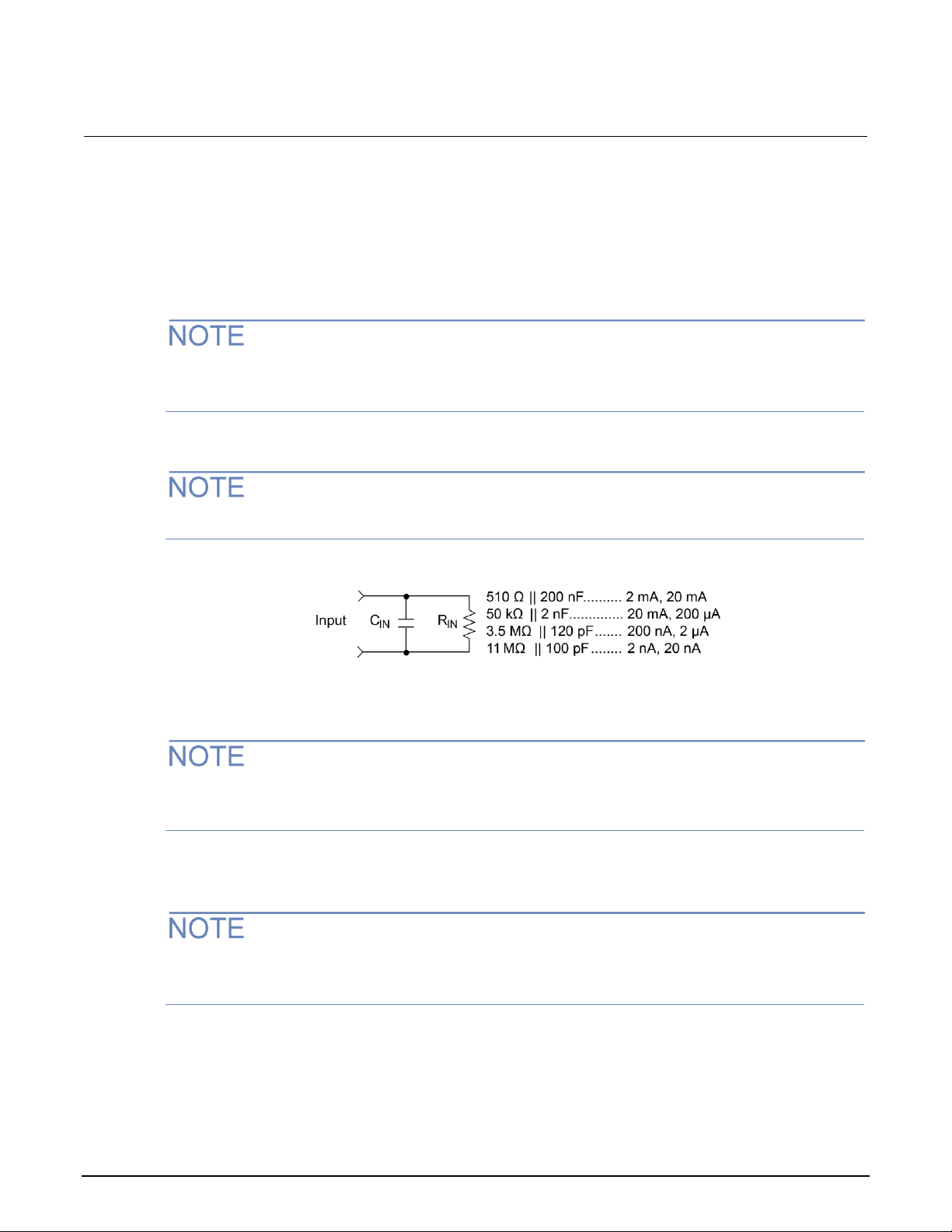
Section 3: Measurement and sourcing voltage Model 6487 Picoammeter / Voltage Source Reference Manual
3-4 6487-901-01 Rev. D October 2020
Zero check and zero correct
Zero check
When zero check is enabled (on), the input amplifier is reconfigured to shunt the input signal to low
with the input impedance.
The ZCHK key toggles zero check on and off. If zero check is enabled (ZEROCHK displayed), press
ZCHK to disable it.
From the front panel, enable or disable zero check by pressing the ZCHK key.
Leave zero check enabled when connecting or disconnecting input signals.
Figure 14: Equivalent input impedance with zero check enabled
Zero correct
The 6487 saves a single Zero Correct value. For best results, acquire a new Zero Correct value after
changing to the desired range.
The 6487 has a zero correct feature to algebraically subtract the voltage offset term from the
measurement.
The REL key toggles zero correct on and off if zero check is enabled. The MON annunciator turns on
when zero correct is enabled.
Page 48

Model 6487 Picoammeter / Voltage Source Reference Manual Section 3: Measurement and sourcing voltage
6487-901-01 Rev. D October 2020 3-5
To zero correct the measurement:
1. Enable zero check. ZEROCHK is displayed.
2. Select the range that will be used for the measurement or select the lowest range.
3. Press REL to enable zero correct. ZCORRECT ON is displayed briefly.
4. Press ZCHK to disable zero check.
5. Readings can now be taken from the display. The MON annunciator indicates that the displayed
reading is zero corrected.
The 6487 will remain zero corrected even if it is upranged. If downranged, re-zero the instrument.
The instrument does not have to be re-zero corrected as long as the ambient temperature remains
stable.
Zero correction cancels the voltage offset term of the amplifier. With both zero check and zero
correct enabled, the instrument may not display a perfectly-zeroed reading. If the 6487 is operating
at or near TCAL, zero correction will have very little effect. TCAL is the internal temperature of the
6487 when it was last calibrated.
SCPI programming - zero check and zero correct
The following are the SCPI zero check and zero correct commands.
Command
Description
Default
Ref
SYSTem
:ZCHeck
[:STATe] <b>
:ZCORrect
[:STATe] <b>
:ACQuire
INITiate
SYSTem subsystem:
Zero check:
Enable or disable zero check.
When zero check is on, the instrument
displays ZEROCHK.
Zero correct:
Enable or disable zero correct.
Acquire a new zero correct
value.
Trigger a reading.
N
ON
OFF
A
B
SYSTem:ZCORrect[:STATe] <b>
This method to perform zero correction is consistent with the way it is performed from the front panel.
That is, zero correction is performed while zero check is enabled. The zero correct state can be
turned on and off repeatedly without requiring a new value. If no ACQ has been performed since the
most recent reset, zero is used for the ACQ value.
Page 49

Section 3: Measurement and sourcing voltage Model 6487 Picoammeter / Voltage Source Reference Manual
3-6 6487-901-01 Rev. D October 2020
SYSTem:ZCORrect:ACQuire
Before sending a SYST:ZCOR:ACQ command, send a SYST:ZCOR:STAT OFF command. Failure
to do so may create a greater chance of obtaining an incorrect zero correct value, particularly if your
last zero correction was accomplished on a different range.
The following command sequence uses the acquire method to zero correct the 200 µA range.
Command
Comments
*RST
Set instrument to known default conditions in one-shot trigger mode.
SYST:ZCH ON
Enable zero check.
CURR:RANG 2E-4
Set instrument to 200 µA range.
INIT
Trigger one reading.
SYST:ZCOR:STAT OFF
Turn zero correct off.
SYST:ZCOR:ACQ
Acquire zero correct value.
SYST:ZCH OFF
Disable zero check.
SYST:ZCOR ON
Perform zero correction.
The INITiate command in the above sequence is used to trigger a reading. This reading is the
offset that is acquired as the zero correct value.
Sending the :ACQuire command while zero check is disabled will result in an error. The command
will not be executed.
SYSTem:ZCORrect[:STATe] <b>
This method to perform zero correction is consistent with the way it is performed from the front panel.
That is, zero correction is performed while zero check is enabled. The zero correct state can be
turned on and off repeatedly without requiring a new value. If no ACQ has been performed since the
most recent reset, zero is used for the ACQ value.
Page 50

Model 6487 Picoammeter / Voltage Source Reference Manual Section 3: Measurement and sourcing voltage
6487-901-01 Rev. D October 2020 3-7
SYSTem:ZCORrect:ACQuire
The zero correct value can only be acquired while zero check is enabled and zero correct state is off.
The internal offset measured at that moment will become the correction value. Zero correction can
then be applied and zero check disabled. This acquire method makes it convenient if you need to
re-zero the instrument often.
Before sending a SYST:ZCOR:ACQ command, send a SYST:ZCOR:STAT OFF command. Failure to
do so means that you have a higher chance of getting a bad zero correct value, particularly if your
last zero correction was accomplished on a different range.
The following command sequence uses the acquire method to zero correct the 200 μA range:
*RST ' Set instrument to known default
' conditions in one-shot trigger mode.
SYST:ZCH ON ' Enable zero check.
CURR:RANG 2E-4 ' Set instrument to 200 μA range.
INIT ' Trigger one reading.
SYST:ZCOR:STAT OFF ' Turn zero correct off.
SYST:ZCOR:ACQ ' Acquire zero correct value.
SYST:ZCH OFF ' Disable zero check.
SYST:ZCOR ON ' Perform zero correction.
The INITiate command in the above sequence is used to trigger a reading. This reading is the
offset that is acquired as the zero correct value. See Triggering (on page 7-1) for more information on
INITiate.
Sending the :ACQuire command while zero check is disabled will result in an error. The command
will not be executed.
Page 51

Section 3: Measurement and sourcing voltage Model 6487 Picoammeter / Voltage Source Reference Manual
3-8 6487-901-01 Rev. D October 2020
Current measurements
Procedure
The maximum safe voltage between picoammeter LO and chassis ground (common mode
voltage) is 505 V. The 6487 does not internally limit the LO to chassis voltage. Exceeding 505
V can create a shock hazard.
If it is possible for the DUT or external supply to present more than 505 V to the input HI, it is
imperative that the connection between input LO and the external voltage source be
sufficiently low impedance and capable of carrying the short-circuit current of the source, in
order that the LO not exceed 505 V.
The LO to chassis breakdown voltage is 505 V. Exceeding this voltage may cause damage to
the instrument.
The maximum input voltage and current to the 6487 is 505 V peak and 21 mA. Exceeding
either of these values may cause damage to the instrument that is not covered by the
warranty.
To achieve optimum precision for low-level current measurements, input bias current and voltage
burden can be minimized by performing the offset correction procedure. See Measurement
considerations (on page 23-1) for more information.
After overloading with high voltage, it may take several minutes for the input current to drop to within
specified limits. Input current can be verified by placing the protection cap on the input connector and
then use the ground link to connect COMMON and CHASSIS ground. With the instrument on the
2 nA range and zero check disabled, allow the reading to settle until the input bias current is within
specifications.
Step 1. Select current function
Press the I | Ω key to make sure the current function is selected.
Page 52

Model 6487 Picoammeter / Voltage Source Reference Manual Section 3: Measurement and sourcing voltage
6487-901-01 Rev. D October 2020 3-9
Step 2. Enable zero check
Zero check should always be enabled before making connection changes. The ZCHK key toggles
zero check on and off. ZEROCHK is displayed when active.
Step 3. Perform zero correction
To achieve optimum accuracy for low current measurements, it is recommended that you zero correct
the picoammeter:
To zero correct the picoammeter:
1. Select the 2 nA range.
2. Press the REL key so that the MON annunciator is on.
Step 4. Select a manual measurement range or enable auto range
Use the RANGE arrow keys to select a manual measurement range or press AUTO to enable auto
range. With auto range enabled, the instrument will automatically select the most sensitive range to
make the measurement. See Range, units, digits, rate, and filters (on page 4-1) for more information.
Step 5. Connect the current to be measured to the picoammeter
A safety shield is advisable whenever floating measurements are being made (see Floating
measurements (on page 2-12)). The metal safety shield must completely surround the noise
shield or floating test circuit and it must be connected to safety earth ground using #18 AWG
or larger wire.
When not making floating measurements, it is recommended that you ground measurement LO at
only one place in the circuit, such as with the ground link connection on the rear panel of the 6487.
Page 53

Section 3: Measurement and sourcing voltage Model 6487 Picoammeter / Voltage Source Reference Manual
3-10 6487-901-01 Rev. D October 2020
Fundamental information on making connections to the picoammeter input is provided in
Measurement Concepts and Connections (on page 2-1).
Figure 15: Connections for amps
Step 6. Disable zero check and take a reading from the display
If the readings are noisy, you may want to use filtering to reduce noise. Use filtering if the noise is
caused by a noisy input signal. Filtering is covered in Range, units, digits, rate, and filters (on page 4-
1).
Page 54

Model 6487 Picoammeter / Voltage Source Reference Manual Section 3: Measurement and sourcing voltage
6487-901-01 Rev. D October 2020 3-11
SCPI programming - current measurements
The following are the SCPI current measurement commands.
Command
Description
Default
Ref
SENSe
:DATA?
:FUNCtion 'CURRent'
INITiate
READ?
SENSe subsystem:
Return latest raw reading.
Select current function.
Trigger one or more readings.
Trigger and return readings.
CURR
A
B
C
D
SENSe:DATA?
This command does not trigger a reading. It returns the last raw reading string. It will not return the
result of any instrument calculation. The reading reflects what is applied to the input. While the 6487
is busy performing measurements, the :DATA? command will not return the reading string until the
instrument finishes and goes into the idle state.
The format that the reading string is returned in is set by commands in DISPlay, FORMat, and
SYSTem (on page 13-1). If there is no reading available when :DATA? is sent, an error (-230) will
occur.
FUNCtion 'CURRent'
Use this command to select the current function instead of the ohms function.
INITiate
To return a fresh (new) reading, you can send the INITiate command to trigger one or more
readings before sending :DATA?. Details on INITiate are provided in Triggering (on page 7-1).
READ?
The READ? command can be used to return new readings. This command triggers and returns the
readings. See SCPI signal-oriented measurement commands (on page 12-1) for more information.
Page 55

Section 3: Measurement and sourcing voltage Model 6487 Picoammeter / Voltage Source Reference Manual
3-12 6487-901-01 Rev. D October 2020
Programming example - current measurements
Command
Comments
*RST
Return 6487 to RST defaults.
FUNC 'CURR'
Select current function.
SYST:ZCH ON
Enable zero check.
CURR:RANG 2e-9
Select the 2 nA range.
INIT
Trigger reading to be used as zero correction.
SYST:ZCOR:STAT OFF
Turn zero correct off.
SYST:ZCOR:ACQ
Use last reading taken as zero correct value.
SYST:ZCOR ON
Perform zero correction.
CURR:RANG:AUTO ON
Enable auto range.
SYST:ZCH OFF
Disable zero check.
READ?
Trigger and return one reading.
Ohms measurements
Overview
To measure ohms with the 6487, set up the voltage source to the desired range, value, and current
limit (see Voltage source operation (on page 3-17)), choose an appropriate current measurement
range (or use autorange), and enable the ohms function.
With the ohms function enabled, the 6487 calculates the measured resistance from the voltage
source value and the measured current. When setting up the voltage source, choose the highest
voltage value as possible for maximum current, keeping in mind such factors as the power dissipation
and voltage coefficient of the resistance being tested.
Ohms measurements can be made using either the DC or alternating voltage modes. See
Alternating voltage ohms mode (on page 3-24).
Page 56

Model 6487 Picoammeter / Voltage Source Reference Manual Section 3: Measurement and sourcing voltage
6487-901-01 Rev. D October 2020 3-13
Procedure
Always turn off power to the 6487 before changing voltage source connections to avoid a
possible shock hazard.
Step 1. Set up voltage source
a. Press either of the V-SOURCE adjustment keys, then use the RANGE key to set the voltage source
range.
b. Set the voltage and current limit to the desired values using the cursor and RANGE keys.
Step 2. Perform zero correction
To achieve optimum accuracy for high resistance measurements, zero correct the picoammeter
before enabling the ohms function. Make sure that zero check and the 2 nA range are selected, then
press the REL key to perform zero correction. MON is displayed when zero correct is enabled.
Step 3. Select a manual current range or enable auto range
Use the manual RANGE keys to select a manual measurement range or press AUTO to enable auto
range. When using manual ranging, choose an appropriate value based on the voltage source setting
and the expected measured resistance.
Page 57

Section 3: Measurement and sourcing voltage Model 6487 Picoammeter / Voltage Source Reference Manual
3-14 6487-901-01 Rev. D October 2020
Step 4. Connect the resistance to be measured to the picoammeter
Basic connections for ohms measurements are shown in the next figure. Note that both the
picoammeter INPUT and the V-SOURCE OUTPUT jacks are connected to the resistance under test.
A safety shield is advisable whenever measurements are being made with voltages over 30 V
dc. The metal safety shield must completely surround the noise shield or floating test circuit
and it must be connected to safety earth ground using #18 AWG or larger wire.
Figure 16: Connections for ohms measurements
Step 5. Select ohms function
Press the I | Ω key to make sure the ohms function is selected.
Step 6. Turn on voltage source
Press the OPER key to turn on the voltage source output. VOLTAGE SOURCE OPERATE is displayed.
Page 58

Model 6487 Picoammeter / Voltage Source Reference Manual Section 3: Measurement and sourcing voltage
6487-901-01 Rev. D October 2020 3-15
Step 7. Disable zero check and take a reading from the display
Press ZCHK to disable zero check and display readings. If the readings are noisy, use filtering to
reduce noise.
For any ohms measurements, the ohms reading is invalid and unknown if the voltage source is in
compliance. Therefore, a value of -9.9e+36 will be returned over the GPIB and the message I-LIMIT
will be displayed on the front panel for both normal readings and buffer recall readings for any ohms
readings where the voltage source went into compliance.
Figure 17: Connections for ohms measurements
Page 59

Section 3: Measurement and sourcing voltage Model 6487 Picoammeter / Voltage Source Reference Manual
3-16 6487-901-01 Rev. D October 2020
SCPI programming - ohms measurements
The following are SCPI ohms measurement commands.
Commands*
Description
Default
Measurements:
[SENSe[1]]
SENSe[1] subsystem:
[:CURRent[:DC]]
:OHMS <b>
Enable or disable ohms function.
OFF
:RANGe <n>
Select manual current range (-0.021 to 0.021A).
:AUTO <b>
Enable or disable auto current range.
ON
Sourcing voltage:
SOURce[1]
SOURce[1] subsystem:
:VOLTage
Voltage source commands:
[:LEVel]
[:IMMediate]
[:AMPLitude] <NRf>
Set output voltage (-505 V to +505 V).
0 V
:RANGe <NRf>
Set voltage source range (10, 50, or 500).
10 V
:ILIMit <NRf>
Set current limit (25μA, 250μA, 2.5mA, or 25mA).
25 mA
:STATe <b>
Turn voltage source output on or off.
OFF
READ?
Trigger and return reading(s).
* Zero correct and zero check commands not included.
[SENSe[1]][:CURRent[:DC]]:OHMS <b>
Use this command to turn the ohms function on or off. When the ohms function is enabled, the 6487
calculates the reading from the measured current and the voltage source setting. Additional OHMS
commands control the alternate voltage ohms mode as described in Alternating voltage ohms mode
(on page 3-24).
SOURce[1]:VOLTage
These commands select the voltage source range, set the source level and current limit, and turn the
source output on and off. Additional voltage source commands control voltage sweeps. See Buffer
and sweeps (on page 6-1) for details.
Page 60

Model 6487 Picoammeter / Voltage Source Reference Manual Section 3: Measurement and sourcing voltage
6487-901-01 Rev. D October 2020 3-17
Programming example - ohms measurements
The following command sequence will perform one zero-corrected resistance measurement:
Command
Comments
*RST
' Return 6487 to GPIB defaults.
FORM:ELEM READ,UNIT
' Measurement, units elements only.
SYST:ZCH ON
' Enable zero check.
RANG 2e-9
' Select the 2nA range.
INIT
' Trigger reading to be used as zero'
correction.
SYST:ZCOR:ACQ
' Use last reading taken as zero ' correct
value.
SYST:ZCOR ON
' Perform zero correction.
RANG:AUTO ON
' Enable auto current range.
SOUR:VOLT:RANG 10
' Select 10V source range.
SOUR:VOLT 10
' Set voltage source output to 10V.
SOUR:VOLT:ILIM 2.5e-3
' Set current limit to 2.5mA.
SENS:OHMS ON
' Enable ohms function.
SOUR:VOLT:STAT ON
' Put voltage source in operate.
SYST:ZCH OFF
' Disable zero check.
READ?
' Trigger and return one reading.
Voltage source operation
Voltage source edit keys
The V-SOURCE up and down keys operate in the same manner as the RANGE up and down keys if
they are not being used to change the voltage source values. The AUTO key acts as a shortcut to set
the V-SOURCE to 0 V.
Page 61

Section 3: Measurement and sourcing voltage Model 6487 Picoammeter / Voltage Source Reference Manual
3-18 6487-901-01 Rev. D October 2020
Configuring the voltage source
To set up the voltage source:
1. Press CONFIG then OPER.
2. Select either the DC mode for normal operation or SWEEP for voltage sweeps. Press ENTER.
3. After the mode is selected, the reading disappears and is replaced with a full-resolution value of
the voltage source with the left-most position highlighted for editing.
4. Use the RANGE up and down keys to change the voltage source range and indicate the range
selected (10 V, 50 V, or 500 V).
5. Enter the desired voltage source value, then press ENTER. Voltage values are changed
immediately from this configuration by pressing the arrow keys. The arrow keys are used to select
the digit being edited and the V-SOURCE up and down keys change the value. The digits will not
increment beyond the limit for the present source range with subsequent source arrow key
presses.
The V-SOURCE up and down keys will operate in the same manner as the RANGE up and down
keys if they are not being used to change the voltage source values.
6. After the voltage value and range is selected, press ENTER to advance to the current limit display
and select the desired current limit. The current limit display offers different choices depending on
the source rang (see the next table) . Pressing ENTER or EXIT from this display returns you to
the normal readings display.
Source range
Selectable current limit
10.0000 V
25 µA
250 µA
2.5 mA
25 mA
50.000 V
25 µA
250 µA
2.5 mA
500.00 V
25 µA
250 µA
2.5 mA
Sourcing voltage
Always turn off the instrument power before changing voltage source connections to avoid a
possible shock hazard.
Page 62

Model 6487 Picoammeter / Voltage Source Reference Manual Section 3: Measurement and sourcing voltage
6487-901-01 Rev. D October 2020 3-19
To source voltage:
Step 1. Set up voltage source
a. Press either of the V-SOURCE adjustment keys, then use the RANGE key to set the voltage source
range.
b. Set the voltage and current limit to the desired values using the cursor and RANGE keys.
Step 2. Connect the load to the source output
Basic connections for sourcing voltage are shown in the next figure.
A safety shield is advisable whenever measurements are being made with voltages over 30 V
dc. Connections for the safety shield are shown in the next figure. The metal safety shield
must completely surround the noise shield or floating test circuit and it must be connected to
safety earth ground using #18 AWG or larger wire.
Page 63

Section 3: Measurement and sourcing voltage Model 6487 Picoammeter / Voltage Source Reference Manual
3-20 6487-901-01 Rev. D October 2020
3. Turn on the voltage source
Press the OPER key to turn on the voltage source output. The VOLTAGE SOURCE OPERATE indicator
will turn on.
Do not connect external sources to the 6487 voltage source. External sources may damage
the 6487 voltage source.
Figure 18: Connections for sourcing voltage
Operate considerations
OPER (operate) key
The OPER (operate) key will function to turn the voltage source off, even if the instrument is operating
under remote control (REM annunciator on), assuming that the LLO (Local Lockout) function has not
been employed. While in remote, the OPER key will only turn the source off. To turn it on, the 6487
must be in local mode.
Page 64

Model 6487 Picoammeter / Voltage Source Reference Manual Section 3: Measurement and sourcing voltage
6487-901-01 Rev. D October 2020 3-21
Voltage source off state
The voltage source is not in a high-impedance state when it is turned off. Rather, it is in a state that
acts just like the voltage source was programmed to 0 V on the selected range. It will enter this state
on power-up after the VOLTAGE SOURCE OPERATE illuminator is displayed.
The safety interlock will cause the voltage source to go into a high-impedance state instead of 0 V
output and the source will stay in the high-impedance state until the operate state is changed to on.
The exception is the 10 V range, where the interlock is optional. The OPERATE light and front panel
display do not indicate the difference between 0 V output and high-impedance output caused by an
open interlock. The interlock status is available by query via remote.
Compliance indication
At any time, it is possible that the voltage source will go into compliance. Should this situation occur,
the OCOMP annunciator will flash and the displayed voltage value for readings of less than 6½ digits
will alternate between showing the value and displaying CMPL. If you are in a menu where the voltage
source value is not shown on the right-most four characters of the display, only the flashing OCOMP
annunciator will be shown.
Open interlock indication
If the interlock is asserted (opened) while the unit is on 50 V or 500 V range, the voltage source will
also technically be in compliance. However, there will be no indication of that status over the front
panel or in the status registers. The open interlock takes precedence.
Page 65

Section 3: Measurement and sourcing voltage Model 6487 Picoammeter / Voltage Source Reference Manual
3-22 6487-901-01 Rev. D October 2020
SCPI commands - voltage source
Commands
Description
Default
SOURce[1]
SOURce[1] subsystem:
:VOLTage
Voltage source commands:
[:LEVel]
[:IMMediate]
[:AMPLitude] <NRf>
Set output voltage level (-505 V to +505 V).
:RANGe <NRf>
Set voltage source range (10 V, 50 V, or 500 V).
0 V
:ILIMit <NRf>
Set current limit (25 μA, 250 μA, 2.5 mA, or 25 mA).*
10 V
:STATe <b>
Turn voltage source output on or off.
25 mA
:INTerlock <b>
Enable or disable interlock for 10 V range.**
OFF
:FAIL?
Query interlock state (1 = asserted, and source
output cannot be turned on).
OFF
* 25 mA not available for 50 V and 500 V ranges
** See Interlock operation (on page 2-14).
[:LEVel] [:IMMediate] [:AMPLitude] <NRf>
Use this command to set the voltage source output level from -505 V to 505 V. Note that if the STATe
is on, then the voltage will change as soon as this command is processed. Sending a value outside of
the present range will generate Error -222 "Parameter Out of Range". To go to a higher value,
change the source range.
RANGe <NRf>
This command selects the range. If you choose a range lower than the current level, the level will be
changed to the maximum value for that range. The range selected will be the one that best
accommodates the value sent. A value of 10.01, for example, will select the 50 V range.
ILIMit <NRf>
Use this command to set the voltage source current limit to 25 μA, 250 μA, 2.5 mA, or 25 mA. The
maximum current limit for the 50 V and 500 V ranges is 2.5 mA.
Page 66

Model 6487 Picoammeter / Voltage Source Reference Manual Section 3: Measurement and sourcing voltage
6487-901-01 Rev. D October 2020 3-23
STATe <b>
This command turns the voltage source output on or off. However, the voltage source output cannot
be turned on if the interlock is asserted. When the voltage source is turned off, the source will be a
low-impedance 0 V source (limited to approximately 1 mA) and will discharge small capacitances.
INTerlock <b>
These commands control the interlock for the 10 V range and query whether or not the interlock is
asserted. Note that for the 50 V and 500 V ranges, this setting is ignored since the interlock is directly
tied to the hardware and cannot be bypassed. Therefore, this command has no effect when the
source is on any range other than the 10 V range.
Attempting to turn off the interlock state while on the 50 V or 500 V ranges will generate a -221
"Settings Conflict" error. Upranging from the 10 V range will always cause the interlock to be
enabled. When you range back down to the 10 V range, the interlock state will be reset to what it was
when you left the 10 V range. See Measurement concepts and connections (on page 2-1) for
additional interlock details.
When the interlock is asserted, the voltage source will change to a high-impedance state.
This situation could leave any connected device charged to the last programmed voltage.
Programming example — voltage
The following command sequence will output 5 V on the 10 V range with a 2.5 mA limit:
Command
Comments
*RST
' Return 6487 to GPIB defaults.
SOUR:VOLT:RANG 10
' Select 10V source range.
SOUR:VOLT 5
' Set voltage source output to 5.
SOUR:VOLT:ILIM 2.5e-3
' Set current limit to 2.5mA.
SOUR:VOLT:STAT ON
' Put voltage source in operate.
Page 67

Section 3: Measurement and sourcing voltage Model 6487 Picoammeter / Voltage Source Reference Manual
3-24 6487-901-01 Rev. D October 2020
Alternating voltage ohms mode
Overview
Ohms can be measured in DC (normal) or alternating voltage (A-V). The alternating voltage ohms
method is especially useful when the resistance or device being measured exhibits high background
currents or high noise currents. These are typical problems seen when measuring high resistances,
devices with moderate to high capacitance, or when adequate shielding is unavailable. By measuring
current differences caused by a change in applied voltage, the alternating voltage method greatly
reduces effects of currents that are not caused by the applied voltage, i.e., not resistive current. The
A-V mode consists of switching the source level between 0 V and a user-selected value. See the
following figure.
Figure 19: Alternating voltage ohms
During each phase, one or several readings are collected into separate buffers for that phase,
designated V-High and V-Zero. A third buffer is created by subtracting the n-th reading of the V-Zero
buffer from its counterpart in the V-High buffer and storing these differences in a buffer designated VDelta. Both from the front panel and remotely, A-V ohms readings always come from the V-Delta
buffer. For more information, see One-shot measurements (on page 3-29).
The purpose of the alternating voltage ohms mode is to improve the accuracy and repeatability of
very high resistance measurements, which are subject to errors from background currents in the test
setup. By taking two current measurements, one at a specific step voltage and a second at 0 V, these
background currents can be largely nulled out and the resistance calculated from the source voltage
and measured current is closer to the actual DUT resistance. Data stored in the buffer can also be
averaged to improve repeatability.
Page 68

Model 6487 Picoammeter / Voltage Source Reference Manual Section 3: Measurement and sourcing voltage
6487-901-01 Rev. D October 2020 3-25
Key test parameters for A-V ohms include the step voltage, measurement time, and the number of
test cycles. The optimum step voltage value depends on the measured resistance and desired
current. The measurement time must be carefully chosen to assure adequate settling during both the
step-voltage (V-High) and 0 V (V-Zero) phases of the measurement. The number of cycles to
measure and average is often a compromise between improvement in repeatability and the overall
measurement time.
The next figure shows a comparison of the A-V voltage and the resulting current. When the voltage
first makes a transition from low to high or high to low, the current initially increases to maximum and
then decays. The decay period depends on the RC time constant () of the circuit being tested.
Figure 20: A-V voltage and current
Page 69

Section 3: Measurement and sourcing voltage Model 6487 Picoammeter / Voltage Source Reference Manual
3-26 6487-901-01 Rev. D October 2020
The next figure demonstrates the advantages of A-V ohms. The decaying curve shows how current
decays time without averaging, while the current plot at the bottom shows substantially improved
results due to averaging of the A-V readings.
Figure 21: Averaged A-V current
Storing A-V ohms readings
Follow the steps below to setup and use the A-V ohms mode.
The following procedure assumes that the 6487 is connected to the DUT.
Before starting the configuration process for A-V ohms, make sure the 6487 is on a current
measurement range high enough to not overflow with the applied V-HI value. Autorange is turned off
while A-V ohms is running.
Page 70

Model 6487 Picoammeter / Voltage Source Reference Manual Section 3: Measurement and sourcing voltage
6487-901-01 Rev. D October 2020 3-27
Menu Item
Description
Default
V-HI
High source voltage value (-505 V to 505 V).
10 V
TIME
Time for each A-V phase.
15 s*
ONE-SHOT
Enable (YES) or disable (NO) one shot mode (one reading per phase).
YES
CYCLES
Number of A-V cycles (one high and low step): 1 to 9999.
3
AUTOCLEAR
Enable (Y) or disable (N) buffer auto clear with A-V ohms.
Y
* Default depends on integration time when entering A-V ohms menu: 15 s for 1 PLC or greater, 1s for 0.1 PLC, and
0.1s for 0.02 PLC.
To store A-V ohms readings:
1. Press CONFIG, then I | Ω to access the ohms configuration menu.
2. Select ALT-VOL, then press ENTER. The unit will prompt for the high voltage value:
V-HI:+10.0000
If you have "regular" readings in the buffer, you will be prompted to clear the buffer. Use CONFIG >
STOR 0000 RDGs > ENTER to clear.
3. Enter the desired high voltage level, then press ENTER. The unit will prompt for the time that the
voltage source value will be at each phase in the A-V cycle:
TIME: 15.00 s
4. Enter the desired time, then press ENTER. The 6487 will prompt for the one-shot mode:
ONE-SHOT: YES
5. Select either YES or NO.
a. Selecting YES will make one current measurement at the end of each phase and two measurements
per cycle to make the V-Delta buffer and return a single reading of the cycle V-Delta measurements
averaged together.
b. Selecting NO will make current measurements continuously during each phase to make a V-Delta
buffer of each cycle, with the points per cycle determined by the integration rate and the TIME specified,
and will return the average decay curve (averaging the V-Delta waveforms of the cycles together, as in
the "Averaged A-V current" graphic in Overview (on page 3-24))):
CYCLES: 0003
See One-shot measurements (on page 3-29) and OHMS:AVOLtage:ONEshot (on page 3-38) for
additional details.
Page 71

Section 3: Measurement and sourcing voltage Model 6487 Picoammeter / Voltage Source Reference Manual
3-28 6487-901-01 Rev. D October 2020
6. Press ENTER. The unit will prompt for the number of A-V cycles.
7. Set the desired number of A-V cycles, then press ENTER. The unit will prompt you as to whether
or not you wish to clear the buffer automatically when a new A-V measurement is started:
AUTOCLEAR: Y
8. Select Y or N, then press ENTER.
9. At this point, the voltage source is in operate at 0 V and the unit displays the message TRIG TO
STRT.
10. To start storing A-V ohms readings, press the TRIG key. The asterisk (*) character will turn on to
indicate the A-V readings are being stored. It will turn off when storage is complete.
To halt the A-V process, press the EXIT key once. The voltage source turns off and I|Ω TO REARM
message will display. A second press of the EXIT key takes you back to the normal reading display.
From this reading display, you can still press I|Ω once and the A-V ohms sequence will again be
armed.
Alternatively from this reading display, press CONFIG > I|Ω and change the selection back to
NORMAL to take regular (not A-V) ohms readings.
Pressing the EXIT or OPER key while A-V ohms is in progress will cause the message I|Ω TO
REARM to appear.
Page 72

Model 6487 Picoammeter / Voltage Source Reference Manual Section 3: Measurement and sourcing voltage
6487-901-01 Rev. D October 2020 3-29
One-shot measurements
The following figure illustrates a measurement when the one-shot A-V ohms mode is enabled.
See OHMS:AVOLtage:ONEShot (on page 3-38) for more information.
Figure 22: One-shot set to YES
Page 73

Section 3: Measurement and sourcing voltage Model 6487 Picoammeter / Voltage Source Reference Manual
3-30 6487-901-01 Rev. D October 2020
The following figure illustrates a measurement when the one-shot A-V ohms mode is disabled.
See OHMS:AVOLtage:ONEShot (on page 3-38) for more information.
Figure 23: One-shot set to NO
Page 74

Model 6487 Picoammeter / Voltage Source Reference Manual Section 3: Measurement and sourcing voltage
6487-901-01 Rev. D October 2020 3-31
Recalling A-V ohms readings
From the front panel, you can view both amps and ohms A-V readings during the recall process. To
do so, press the RECALL key, then use the left and right arrow keys to cycle among amps, ohms,
voltage source, and time values for each reading. Use the RANGE up and down arrow keys to cycle
through individual readings or buffer statistics, which are calculated on the basis of the amps
readings. See the following figure.
Figure 24: A-V ohms reading recall sequence
Note that the maximum current will result in a minimum ohms reading and vice versa. The MIN
reading applies to the minimum current (maximum ohms), while the MAX reading applies to the
maximum current (minimum ohms).
Expressing the standard deviation in ohms is not meaningful; therefore it cannot be viewed in ohms
and will always show a blank ("---------"). The same applies for the Pk-Pk display. Average will
be converted to ohms.
Page 75

Section 3: Measurement and sourcing voltage Model 6487 Picoammeter / Voltage Source Reference Manual
3-32 6487-901-01 Rev. D October 2020
Operating considerations
Range
The ranges for current measurements are listed in the next table.
nA
mA
mA
2 nA
2 mA
2 mA
20 nA
20 mA
20 mA
200 nA
200 mA
The full scale readings for every measurement range are 5 % over range. For example, on the 20 µA
range, the maximum input current is ±21 µA. Input values that exceed the maximum readings cause
the overflow message (OVRFLOW) to be displayed.
Filtering
The median and average filters are not used in the A-V ohms mode. Once the A-V ohms process is
complete, the state of the filters will be restored.
Rate and autozero
During A-V ohms, integration rates are restricted to either 0.02 PLC, 0.1 PLC, 1 PLC, 6 PLC, or 60
PLC. Autozero is turned off but restored after completion if it was previously on. If the integration rate
is set to any other value, it will be set to the closest of these settings. However, the original integration
rate will not be restored at the conclusion of the A-V ohms cycle.
Integration times of 0.02 PLC and 0.1 PLC will automatically cause the display to be disabled during
the A-V ohms run. After the desired number of cycles has completed (or an OHMS:AVOL:ABORt
command is received), the display will be restored.
Page 76

Model 6487 Picoammeter / Voltage Source Reference Manual Section 3: Measurement and sourcing voltage
6487-901-01 Rev. D October 2020 3-33
Triggering considerations
When A-V ohms is selected, the ARM-IN trigger source is forced to TIMER and the time interval
selected will be slightly higher than that required for the A/D integration. For example, at 1 PLC the
integration time is 16.67 ms, so sending the OHM:AVOL:ARM command will set the ARM-IN timer
interval to 18 ms. See the following table. Likewise, the ARM-IN count will be set to INFinite.
When exiting A-V ohms with an AVOL:OHMS:ABOR command or when the desired number of cycles
has completed, the previous trigger model settings will be restored.
See Triggering (on page 7-1) for more information.
PLC
50 Hz measurement interval
(milliseconds)
60 Hz measurement interval
(milliseconds)
0.02
0002
0002
0.1
0004
0004
1
0022
0018
5 (50 Hz)
6 (60 Hz)
0102
0102
50 (50 Hz)
60 (60 Hz)
1002
1002
Trigger state after A/V ohms
Once an A-V ohms reading sequence has been completed, the instrument will be left in the trigger
IDLE state. If you are operating remotely (GPIB or RS-232), over the front panel, normal readings will
resume after completing A-V ohms (although the "I/Ω TO REARM" message will obscure these
readings until you press EXIT). Send an INIT:IMM command to resume taking readings. See
Triggering (on page 7-1) for more information.
Normal ohms with A-V ohms
Normal ohms (SENS:OHMS:STAT) is not compatible with A-V ohms since the latter relies on
differences between current measurements in time. Therefore, the I | Ω key is ignored and the
SENS:OHMS:STAT command is rejected with an error +850 "Not Allowed with A-V Ohms"
while A-V ohms is armed.
Page 77

Section 3: Measurement and sourcing voltage Model 6487 Picoammeter / Voltage Source Reference Manual
3-34 6487-901-01 Rev. D October 2020
Buffer operation
The same memory space is used for the regular 3,000 point buffer as for the three A-V ohms buffers.
If there are already readings in the buffer, attempting to arm A-V ohms readings results in a -225
"Out of Memory" error. To avoid inadvertently writing over any desired readings, either send a
TRAC:CLEar command over the bus or attempt to store 0 readings to manually clear the buffer from
the front panel. From the front panel, attempting to select A-V ohms from the CONFIG -> OHMS
menu will generate the message "CLEAR BUFFER" if there are already readings in the buffer.
If the buffer has stored A-V ohms readings, you will be given the "CLEAR BUFFER" prompt so that
you do not inadvertently write over the A-V ohms data you have collected.
When working remotely, sending the TRAC:FEED:CONT NEXT command while there are A-V ohms
readings in the buffer will result in a -225 "Out of Memory" error. Send TRAC:CLEar to clear out
the buffer before attempting to store buffer readings.
Command restrictions
While a sweep is in progress, most voltage source control commands, trigger model commands, and
buffer (TRACe subsystem) commands are locked out. Sending any of the commands listed below
generates the error code +840 "Not allowed with sweep on":
SOUR:VOLT[:LEV][:IMM][:AMPL]
SOUR:VOLT:STATe
SOUR:VOLT:RANGe
ARM:SEQ1:COUN
ARM:SEQ1:SOUR
ARM:SEQ1:TIM
TRIG:SEQ1:COUN
TRIG:SEQ1:SOUR
TRIG:SEQ1:DEL
TRIG:SEQ1:DEL:AUTO
TRAC:FEED
TRAC:FEED:CONT
TRAC:POIN
TRAC:CLE
TRAC:TST:FORM
Page 78

Model 6487 Picoammeter / Voltage Source Reference Manual Section 3: Measurement and sourcing voltage
6487-901-01 Rev. D October 2020 3-35
SENS:CURR:DC:NPLC
Over the front panel, pressing any key (for example RATE) that would change one of the settings
associated with this command will automatically cause the buffer to be cleared if the following
conditions are true:
• There are A-V ohms readings present in the buffer.
• SENS:CURR:OHMS:AVOL:CLE:AUTO is set to OFF.
• The front panel ohms mode is set for ALT-VOL.
If the buffer is cleared by one of these key presses, a "BUF CLEARED" message will be displayed.
Regardless of whether the buffer gets cleared by the key press (it does not, for instance, if the
OHMS:AVOL:CLE:AUTO setting is true), you also will have to re-enter the CONFIG-> I | Ω menu to
select a new time interval before making another A-V ohms run from the front panel.
Interlock
Attempting to run A-V ohms from the front panel while the interlock is open and failing will result in the
error message “CLOSE INTLCK” being displayed. If trying to run remotely with the :ARM command
the error event +802 “Output Blocked by Interlock” is generated.
SCPI commands — A-V ohms
Command
Description
Default
To make measurements:
[SENSe[1]]
SENSe[1] subsystem:
[:CURRent[:DC]]
Current measurement commands:
:OHMS
Ohms mode commands:
:AVOLtage
Path to A-V ohms commands:
[:ARM]
Arm A-V ohms mode.
[:ARM]?
Query if A-V ohms is armed. (1 = armed).
:ABORt
Abort A-V ohms mode.
:VOLTage <NRf>
Set high voltage value (-505 V to 505 V).
10 V
:TIME <NRf>
Set time interval for each phase.
15 s*
:POINts?
Query number of points.
:ONEShot <b>
Enable or disable one-shot mode.
ON
:CYCLes <NRf>
Set number of A-V cycles (1 to 9999).
3
:UNITs <name>
Select AMPS or OHMS units.
AMPS
:CLEar
Clear A-V ohms buffer.
:AUTO <b>
Enable/disable A-V buffer auto clear.
ON
:BCOunt?
Query number of A-V points.
Page 79

Section 3: Measurement and sourcing voltage Model 6487 Picoammeter / Voltage Source Reference Manual
3-36 6487-901-01 Rev. D October 2020
To access A/V readings:
TRACe
TRACe subsystem:
:DATA? [BUFFER]
Request data from BUFFER.
BUFFER
:MODE?
Query buffer mode: DC or AVOLtage.
CALCulate3
CALCulate3 Subsystem:
:FORMat <name>
Select buffer statistic; MINimum, MAXimum, MEAN,
SDEViation, or PKPK.
MEAN
:DATA?
Read the selected buffer statistic.
* Default depends on integration rate: 15 s for 1 PLC or greater, 1 s for 0.1 PLC, and 0.1 s for 0.02 PLC.
OHMS:AVOLtage[:ARM]
This command arms the A-V ohms mode. Once this command is sent, the next INIT command starts
A-V readings. Sending this command, if there are normal readings in the buffer, results in error -225
"Out of Memory". Use TRAC:CLEar to clear out the buffer. If there are A-V ohms readings in the
A-V buffers, this command will automatically clear those buffers in preparation for the next run if the
OHMS:AVOL:CLEar:AUTO state is true. Note that arming the A-V ohms mode will also set the source
value to zero and turn operate on.
The ARM command is not allowed if the picoammeter is in auto range (CURR:RANG:AUTO ON);
attempting to send the ARM command if autoranging results in error +852 "No A-V ohms with
Autorange". If the combination of integration time and programmed TIME interval would result in
more than the maximum 1,000 readings per phase, error +853 "Too Many A-V Ohms
Readings" is returned.
The :ARM? query returns 1 if A-V ohms has been armed even if the unit is still in the idle state.
No commands except for INIT should be sent after sending the OHMS:AVOL:ARM command.
OHMS:AVOLtage:ABORt
This command closes the A-V buffer and resets the source value back to 0 V. The source is also
placed in standby.
OHMS:AVOLtage:VOLTage <NRf>
This command sets the positive voltage. During each A-V cycle, the voltage source level alternates
between 0 V and this programmed value.
Page 80

Model 6487 Picoammeter / Voltage Source Reference Manual Section 3: Measurement and sourcing voltage
6487-901-01 Rev. D October 2020 3-37
OHMS:AVOLtage:TIME <NRf>
This command sets the time interval in seconds that the source will be in each phase. The number of
readings collected per phase will be determined by the integration period and trigger delay, if any.
Note that changing the time will clear out any A-V buffer data that has been collected regardless of
whether CLEar:AUTO is enabled or not. Sending a time value that would result in more than the
maximum of 1000 readings per phase based on the present integration time will result in error +853
"Too Many A-V Ohms Readings". The default time interval depends on the integration time
selected.
60 Hz
0.02 PLC
0.1 PLC
1 PLC
6 PLC
60 PLC
Time (ms)
2 4 18
102
1002
50 Hz
0.02 PLC
0.1 PLC
1 PLC
5 PLC
50 PLC
Time (ms)
2 4 22
102
1002
OHMS:AVOLtage:POINts?
This query returns the number of points per phase based on the user-supplied TIME value above. If
the number of points would be greater than the maximum of 1,000 (for example, if you had set a new
integration rate but had not changed the AVOL:TIME value), then -999 will be returned. A -999
return value indicates that you cannot send the OHMS:AVOL:ARM command until you adjust either the
time interval or the integration rate to obtain a valid number of points.
Page 81

Section 3: Measurement and sourcing voltage Model 6487 Picoammeter / Voltage Source Reference Manual
3-38 6487-901-01 Rev. D October 2020
OHMS:AVOLtage:ONEShot <b>
This command controls the one-shot A-V ohms mode. If the one-shot mode is ON, then only a single
reading is collected for each voltage phase at the end of the TIME interval given above for each cycle
and only one reading is returned by averaging V-Delta of each cycle. If one-shot mode is OFF, then
an average waveform of all the cycle's V-Delta is returned, as in the following figure.
Figure 25: Averaged A-V current
See One-shot measurements (on page 3-29) for more information.
OHMS:AVOLtage:CYCLes <NRf>
This command sets the number of cycles to run A-V ohms. A cycle is defined as one V-High and one
V-Zero step.
OHMS:AVOLtage:UNITs <name>
This command sets either amperes or ohms for the the A-V ohms returned and stored readings.
OHMS:AVOLtage:CLEar
CLE manually clears the A-V ohms buffers. TRAC:CLEar will also do the same thing. AUTO ON
enables A-V ohms auto-clear. If enabled, arming the next A-V ohms run will clear out the buffers. If
disabled, subsequent A-V ohms runs will get averaged in with the saved readings.
Page 82

Model 6487 Picoammeter / Voltage Source Reference Manual Section 3: Measurement and sourcing voltage
6487-901-01 Rev. D October 2020 3-39
OHMS:AVOLtage:BCOunt?
This query returns the number of V-High and V-Low cycles that have been averaged to result in the
data stored in the A-V ohms buffer.
TRACe:DATA? [BUFFER]
This query returns data either from the normal buffer or the A-V ohms buffer. If A-V ohms is not on
and no A-V ohms readings have been collected, normal buffer readings will be returned. If A-V ohms
readings have been collected, A-V ohms readings will be returned.
TRACe:MODE?
This query returns the type of data stored in the buffer (either DC or AVOLtage).
Programming example — A-V ohms measurements
The following command sequence will perform A-V ohms measurements with a 5 V high value, 10 s
per phase, and 5 A-V cycles:
*RST ' Return 6487 to GPIB defaults.
TRAC:CLE ' Clear buffer of all readings.
RANG 20e-3 ' Select 20mA range (turn off auto).
OHMS:AVOL:VOLT 5 ' Set high voltage to 5V.
OHMS:AVOL:ONES OFF ' Disable one-shot mode.
OHMS:AVOL:CLE:AUTO ON ' Enable buffer auto clear.
OHMS:AVOL:TIME 10 ' Set time per phase to 10s. (A)
OHMS:AVOL:CYCL 5 ' Set number of A-V cycles to 5. (B)
OHMS:AVOL:UNIT OHMS ' Select ohms units.
SYST:ZCH OFF ' Disable zero check.
OHMS:AVOL:ARM ' Arm A-V ohms, turn on source.
INIT ' Trigger A-V readings.
' Wait for time [(A) 2] cycles (B)
' before requesting readings. 100s in
' this example.
TRAC:DATA? ' Request data from A-V ohms buffer.
Page 83

In this section:
Range, units, and digits ............................................................4-1
Rate ..........................................................................................4-5
Damping....................................................................................4-6
Filters ........................................................................................4-7
Range, units, and digits
Range
The ranges for current measurements are listed in the following table.
nA
μA
mA
2 nA
2
2 mA
20 nA
20
20 mA
200 nA
200
The full scale readings for every measurement range are 5% over range. For example, on the 20 μA
range, the maximum input current is ±21 μA. Input values that exceed the maximum readings cause
the overflow message (OVRFLOW) to be displayed.
Manual ranging
To select a range, press the RANGE up or down key. The instrument changes one range per press. If
the instrument displays the OVRFLOW message on a particular range, select a higher range until an
on-range reading is displayed. Use the lowest range possible without causing an overflow to ensure
best accuracy and resolution.
Autoranging
When using autorange, the instrument automatically goes to the most sensitive available range to
measure the applied signal. Up-ranging occurs at 105% of range, while down-ranging occurs at the
range value. For example, if on the 20 μA range, the instrument will go up to the 200 μA range when
the input signal exceeds 21 μA. While on the 200 μA range, the instrument will go down to the 20 μA
range when the input level goes below 20 μA.
Section 4
Range, units, digits, rate, and filters
Page 84

Section 4: Range, units, digits, rate, and filters Model 6487 Picoammeter / Voltage Source Reference Manual
4-2 6487-901-01 Rev. D October 2020
The AUTO key toggles the instrument between manual ranging and autoranging. The AUTO
annunciator turns on when autoranging is selected. To disable autoranging, press AUTO or the
RANGE up or down key. Pressing AUTO to disable autoranging leaves the instrument on the present
range.
Each time an autorange occurs, a search for every available range of the selected function is
performed. The time it takes to perform the search could slow down the range change speed
significantly. Setting upper and/or lower autorange limits can reduce search time.
Range limits and groups are not in effect for manual ranging. Every range is accessible with manual
range selection.
Autorange limits
Search time for amps can be reduced by setting upper and/or lower autorange limits. For example, if
you know the maximum input will be around 1 μA, set the upper current range limit to 2 μA. This
eliminates the 20 μA, 200 μA, 2 mA, and 20 mA ranges from the search, thereby increasing the range
change speed. Should the input exceed 2.1 μA, the OVRFLOW message will be displayed.
To set upper and lower autorange limits:
1. Press CONFIG key (CONFIGURE: will be displayed).
2. Display the desired limit.
a. Press the RANGE up key to display the present UPPER range limit.
b. Press the RANGE down key to display the present LOWER range limit.
3. Scroll through the available range limits using the up or down RANGE key.
4. Press ENTER when the desired range is flashing.
If you attempt to select an incompatible range limit, it will be ignored and TOO LARGE or TOO SMALL
will be displayed briefly. For example, if the lower range limit is 20 μA, setting the upper limit to 2 μA
will display the TOO SMALL error.
Page 85

Model 6487 Picoammeter / Voltage Source Reference Manual Section 4: Range, units, digits, rate, and filters
6487-901-01 Rev. D October 2020 4-3
Units
Changing the display resolution is not allowed if displaying readings in scientific notation.
Readings can be displayed using engineering (ENG) or scientific (SCI) notation. Perform the following
steps to change the units setting:
1. Press MENU key.
2. Scroll down to the UNITS item using the up or down RANGE key.
3. Press ENTER to select setting.
4. Use the up or down key to display the desired units setting.
5. Press ENTER.
6. Press EXIT to return to normal display.
The units setting can only be changed from the front panel. Scientific notation provides more
resolution on small values than engineering units.
Digits
The DIGITS key sets display resolution for the 6487. Display resolution can be set from 3½ to 6½
digits. This single global setting affects display resolution for all measurement ranges.
To set display resolution, press (and release) the DIGITS key until the desired number of digits is
displayed.
Changing the integration rate does not change display resolution. Changing display resolution does
not change the rate setting.
The voltage source value will not be displayed with the 6½ digit setting.
Page 86

Section 4: Range, units, digits, rate, and filters Model 6487 Picoammeter / Voltage Source Reference Manual
4-4 6487-901-01 Rev. D October 2020
SCPI programming for range and digits
Commands
Description
Default
[:CURRent]
:RANGe
[:UPPer] <n>
: AUTO <b>
:ULIMit <n>
:LLIMit <n>
For Digits:
DISPlay
:DIGits <n>
Measure current:
Range selection:
Specify expected reading; -0.021 to 0.021 A.
Enable or disable autorange.
Specify upper range limit for autorange:
-0.021 to 0.021 A.
Specify lower range limit for autorange:
-0.021 to 0.021 A.
DISPlay subsystem:
Set display resolution: 4 to 7, where <n> of:
4 = 3½ digit resolution
5 = 4½ digit resolution
6 = 5½ digit resolution
7 = 6½ digit resolution
Rational numbers can be used. For
example, to set 5 resolution send a value
of 4.5. The 6487 rounds it to 5.
200 μA
ON
20 mA
2 nA
6
Programming example — range and digits
The following command sequence selects the 20 mA range and sets display resolution to 3:
Command
Comments
*RST
' Restore RST defaults .
CURR:RANG 0.02
' Set to 20 mA range.
DISP:DIG 3.5
' Set display resolution to 3H digits.
The following table lists the instrument ranges and values
Range
<n> value
Display (5H digit resolution)
20 mA
2 mA
200 μA
20 μA
2 μA
200 nA
20 nA
2 nA
2E-2 or 0.02
2E-3 or 0.002
2E-4 or 0.0002
2E-5 or 0.00002
2E-6 or 0.000002
2E-7 or 0.0000002
2E-8 or 0.00000002
2E-9 or 0.000000002
00.0000 mA
0.00000 mA
000.000 μA
00.0000 μA
0.00000 μA
000.000 nA
00.0000 nA
0.00000 nA
Page 87

Model 6487 Picoammeter / Voltage Source Reference Manual Section 4: Range, units, digits, rate, and filters
6487-901-01 Rev. D October 2020 4-5
Rate
The RATE key selects the integration time of the analog-to-digital converter. This is the period of time
the input signal is measured. The integration time affects the amount of reading noise, as well as the
ultimate reading rate of the instrument. The integration time is specified in parameters based on a
number of power line cycles (NPLCs), where 1 PLC for 60 Hz is 16.67 ms (1/60) and 1 PLC for 50 Hz
(and 400 Hz) is 20 ms (1/50).
Generally, the 6487 has a parabola-like shape for its speed vs. noise characteristics and is shown in
the next figure. The 6487 is optimized for the 1 PLC to 10 PLC reading rate. At these speeds, the
6487 will make corrections for its own internal drift and still be fast enough to settle a step response
<100 ms.
Figure 26: Speed versus noise characteristics
The rate setting is global for all ranges. Therefore, it does not matter what range is selected when you
set the rate.
There are two ways to set the rate. You can select slow, medium, or fast by using the RATE key or
you can set the number of power cycles from the NPLC menu that is accessed by pressing CONFIG /
LOCAL (while in LOCAL) and then RATE.
The available RATE key selections are as follows:
▪ SLOW — Selects the slowest preset integration time (6 PLC for 60 Hz or 5 PLC for 50 Hz).
The SLOW rate provides better noise performance at the expense of speed.
▪ MED — Selects the medium integration time (1 PLC). Select the MED rate when a
compromise between noise performance and speed is acceptable.
▪ FAST — Selects the fastest preset integration time (0.1 PLC). Select the FAST rate if speed
is of primary importance (at the expense of increased reading noise).
Press the RATE key until the desired rate is displayed.
Page 88

Section 4: Range, units, digits, rate, and filters Model 6487 Picoammeter / Voltage Source Reference Manual
4-6 6487-901-01 Rev. D October 2020
To set the NPLC:
1. Press CONFIG / LOCAL and then RATE to display the present PLC value.
2. Use the arrow keys to adjust to the desired PLC value. Valid values are:
60 Hz operation: 0.01 to 60
50 Hz operation: 0.01 to 50
3. Press ENTER.
The SLOW, MED, or FAST annunciator will only turn on if the set PLC value corresponds exactly to
the slow (5 or 6 PLC for the respective frequency of 50 or 60 Hz), medium (1 PLC), or fast (0.1 PLC)
integration rate. For example, with the integration rate set to 2 PLC, none of the rate annunciators
are displayed.
SCPI programming — rate
The following table contains the path and the command to set the rate.
Command
Description
Default
[:SENSe]
[:CURRent]
:NPLCycles <n>
SENSe subsystem:
Specify integration rate: 0.01 (PLCs) to
60.0 (60 Hz) or 50.0 (50 Hz)
6.0 (60 Hz)
5.0 (50 Hz)
Programming example - rate
The following command sets the integration rate for all measurement ranges to 2 PLC:
CURR:NPLC 2 ' Set integration rate to 2 PLC.
Damping
High capacitance at the input will increase reading noise. This capacitance can be attributed to a long
input cable, the capacitance of the source, or a combination. Enabling damping (analog filtering) will
reduce this type of noise for current measurements. However, damping will also slow down the
response of the measurement.
Use damping to reduce noise caused by input capacitance. Use filtering to reduce noise caused by a
noisy input signal.
Page 89

Model 6487 Picoammeter / Voltage Source Reference Manual Section 4: Range, units, digits, rate, and filters
6487-901-01 Rev. D October 2020 4-7
To toggle damping on or off, press the DAMP key. DAMP ON or DAMP OFF will be be displayed to
indicate the present state of damping. Note that the FILT annunciator is used for both the analog
damping filter and the two types of digital filters.
Command
Description
Default
[:SENSe]
[:CURRent]
:DAMPing
[:STATe] <b>
[:STATe]?
SENSe subsystem:
Path to current functions
Control damping (analog filter)
Enable or disable damping filter
Query damping filter state
ON
Filters
Filtering stabilizes erratic measurements caused by noisy input signals. The 6487 uses median and
digital filters. The displayed, stored, or transmitted reading is simply the result of the filtering
processes. Note that both the median and digital filters can be used at the same time.
With both filters enabled, the median filter operation is performed first. After the median filter yields a
reading, it is sent to the stack of the digital filter. Therefore, a filtered reading will not be displayed
until both filter operations are completed.
The settings for the filter are global. The FILT key is used to control both filters. When either the
median or digital filter is enabled, the FILT annunciator is on. Note that the FILT annunciator is used
for both the digital filters and the analog damping filter.
Page 90

Section 4: Range, units, digits, rate, and filters Model 6487 Picoammeter / Voltage Source Reference Manual
4-8 6487-901-01 Rev. D October 2020
Median filter
The median filter is used to determine the reading at the midpoint of a group of readings that are
arranged according to size. For example, assume the following readings:
20 mA, 1 mA, 3 mA
The readings are rearranged in an ascending order as follows:
1 mA, 3 mA, 20 mA
From the above readings, it is apparent that 3 mA is the median (middle-most) reading. The number
of sample readings used for the median calculation is determined by the selected rank (1 to 5) as
follows:
Sample readings = (2 ´ R) + 1
where R is the selected rank (1 to 5)
For example, a rank of 5 will use the last 11 readings to determine the median;
(2 ´ 5) + 1 = 11. Each new reading replaces the oldest reading and the median is then determined
from the updated sample of readings.
The median filter operates as a moving type filter. For example, if the median filter is configured to
sample 11 readings (Rank 5), the first filtered reading will be calculated (and displayed) after 11
readings are acquired and placed in its filter stack. Each subsequent reading will then be added to the
stack (oldest reading discarded) and another median filter reading will be calculated and displayed.
The median filter operation will reset (start over) whenever the Zero Check operation is performed or
the range is changed.
Median filter control
To configure the median filter:
1. Press the CONFIG key.
2. Press the FILT key.
3. Select MEDIAN, then press ENTER.
4. Change the display to MEDIAN ON, then press ENTER.
5. The present rank will be displayed.
6. Use the RANGE keys to display the desired rank.
7. Press ENTER to set. To return to the previously set value, press EXIT instead of ENTER.
Digital filter
Page 91

Model 6487 Picoammeter / Voltage Source Reference Manual Section 4: Range, units, digits, rate, and filters
6487-901-01 Rev. D October 2020 4-9
An additional filter parameter is type, either moving or repeating.
Moving filter: Each time a reading conversion occurs, the readings in the stack are averaged to yield
a single filtered reading. The stack type is first-in, first-out. After the stack fills, the newest reading
conversion replaces the oldest. Note that the instrument does not wait for the stack to fill before
releasing readings.
Repeating filter: Takes a selected number of reading conversions, averages them, and yields a
reading. It then flushes its stack and starts over.
Figure 27: Moving and repeating digital filter types
Response time
The various filter parameters have the following effects on the time needed to display, store, or output
a filtered reading.
The digital filter operation will reset (start over) whenever the zero check operation is performed or
the range is changed.
Page 92

Section 4: Range, units, digits, rate, and filters Model 6487 Picoammeter / Voltage Source Reference Manual
4-10 6487-901-01 Rev. D October 2020
To configure the average filter:
1. Press CONFIG > FILT.
2. Set the display to AVERAGE ON, then press ENTER. The present number of reading conversions
to average (filter count) will be displayed.
3. Set the filter count (2 to 100):
▪ Use the RANGE and arrow keys to display the desired filter count value at the RDGS prompt.
▪ Press ENTER to set.
4. Set the filter type:
▪ Use the RANGE keys to display the desired filter type at the TYPE: prompt.
▪ Press ENTER to set.
SCPI programming — filters
The following table contains SCPI commands for filters.
Command
Description
Default
For median filter:
[:SENSe[1]]
:MEDian
:RANK <n>
[:STATe] <b>
For digital filter:
[:SENSe[1]]
:AVERage
:TCONtrol <name>
:COUNt <n>
[:STATe] <b>
SENSe subsystem:
Median Filter:
Specify filter rank: 1 to 5.
Enable or disable median filter.
SENSe Subsystem:
Digital filter:
Select filter control: MOVing or
REPeat.
Specify filter count: 2 to 100.
Enable or disable digital filter.
1
OFF
MOV
10
OFF
Programming example - rate
The following command sequence configures and enables both filters:
' Median Filter:
MED:RANK 5 ' Set rank to 5.
MED ON ' Enable median filter.
' Digital Filter:
AVER:COUN 20 ' Set filter count to 20.
AVER:TCON MOV ' Select moving filter.
AVER ON ' Enable digital filter.
Page 93

In this section:
Relative .....................................................................................5-1
mX+b, m/X+b (reciprocal), and logarithmic ...............................5-4
Relative
Relative (Rel) nulls an offset or subtracts a baseline reading from present and future readings. When
a Rel value is established, subsequent readings will be the difference between the actual input and
the Rel value.
Displayed reading = Actual input - rel value
A Rel value is the same for all measurement ranges. For example, a Rel value of 1E-6 is 1 μA on the
2 μA range. It is also 1 μA on the 20 μA range and the 200 μA range. Note changing ranges does not
disable Rel.
When a Rel value is larger than the selected range, the display is formatted to accommodate the
reading. However, this does not increase the maximum allowable input for that range. An overrange
input signal will still cause the display to overflow. For example, on the 20 μA range, the 6487
overflows for a 21 μA input.
Rel can be used on the result of the mX+b, m/X+b, or LOG calculations. However, Rel will be
disabled whenever a math function is enabled or disabled.
Setting and controlling relative
From the front panel, you can use the input reading as the Rel value or you can manually enter the
value.
Section 5
Relative, mX+b, m/X+b, and log
Page 94
Section 5: Relative, mX+b, m/X+b, and log Model 6487 Picoammeter / Voltage Source Reference Manual
5-2 6487-901-01 Rev. D October 2020
REL key
When the REL key is used to enable Rel, the present display reading is used as the Rel value.
To set a Rel value:
1. Disable zero check by pressing ZCHK.
2. Display the reading you want as the Rel value. This could be a zero offset reading that you want
to null out or it could be an applied level that you want to use as a baseline.
3. Press REL. The REL annunciator turns on and subsequent readings will be the difference
between the actual input and the Rel value.
4. To disable Rel, press the REL key a second time or select a different measurement function.
When Rel is disabled, the Rel value is remembered. To reinstate the previous Rel value, press
CONFIG > REL > ENTER. If the REL is disabled and then REL is pressed again, it will determine
and set a new null value. With zero check enabled, the REL key controls zero correct, not relative.
Displaying or manually entering REL
Pres CONFIG and then REL to display the present Rel value. This displayed value can be enabled by
pressing ENTER, or a different Rel value can be entered and enabled.
1. Press CONFIG and then REL. The present Rel value will be displayed.
2. To change the Rel value, use the RANGE and cursor keys and change the value. To change Rel
polarity, place the cursor on the polarity sign and press either manual RANGE key. To change
the Rel range, place the cursor on the range symbol (at the end of the reading) and use the
manual RANGE keys.
3. With the desired Rel value displayed, press ENTER to enable Rel.
The following table lists the range symbols for Rel values.
Symbol
Prefix
Exponent
p
pico-
10
-12
n
nano-
10-9
μ
micro-
10-6 m milli-
10-3 ˆ (none)
100 K kilo-
103 M mega-
106 G giga-
109 T tera-
1012
Page 95

Model 6487 Picoammeter / Voltage Source Reference Manual Section 5: Relative, mX+b, m/X+b, and log
6487-901-01 Rev. D October 2020 5-3
SCPI programming — relative
Command
Description
Default
CALCulate2
Path to configure and control limit testing (CALC2):
:FEED <name>
Specify reading to Rel: SENSe[1]or CALCulate[1].
SENS1
:NULL
Configure and control Relative.
:ACQuire
Use input signal as Rel value.
:OFFSet <NRf>
Specify Rel value: -9.999999e20 to 9.999999e20.
:STATe <b>
Enable or disable Rel.
0.0
:DATA?
Return readings triggered by INITiate.
OFF
:DATA:LATest?
Return only the latest reading.
INITiate
Trigger one or more readings.
:FEED <name>
When SENSe[1] is selected, the Rel operation is performed on the input signal. When
CALCulate[1] is selected, the Rel operation is performed on the result of the mX+b or m/X+b
calculation.
:STATe <b>
This command toggles the state of Rel without acquiring new values. This operation is different than
the REL key on the front panel (which toggles the Rel state), as the front panel key acquires new
values when pressed (unless CONFIG is pressed first). If a NULL value has not been acquired before
enabling Rel, 0.000000E+00 is used.
Page 96
Section 5: Relative, mX+b, m/X+b, and log Model 6487 Picoammeter / Voltage Source Reference Manual
5-4 6487-901-01 Rev. D October 2020
:DATA? and :DATA:LATest?
With Rel enabled, these commands will return one or more readings, but they will not trigger new
readings. Use the INITiate command to trigger new readings.
If the instrument is programmed to perform a finite number of measurements, the :DATA? command
will return all readings after the last reading is taken. The :DATA:LATest? command will only return
the latest reading.
If the instrument is programmed to perform an infinite number of measurements (arm count or trigger
count set to infinite), you cannot use the :DATA? command to return readings. However, you can use
the :DATA:LATest? command to return the last reading after aborting the measurement process.
After sending the INITiate command to start the measurement process, use the ABORt command
to abort the measurement process, then use :DATA:LATest? to return to the last reading.
Programming example — relative
This program fragment establishes a 1 μA baseline for measurements:
Command
Comments
CALC2:NULL:OFFS 1e-6
' Set Rel value of 1 A.
CALC2:NULL:STAT ON
' Enable Rel.
CALC2:FEED SENS
' Rel input signal.
SYST:ZCH OFF
' Turn off zero check.
INIT
' Trigger reading(s).
CALC2:DATA?
' Request Rel’ed reading.
mX+b, m/X+b (reciprocal), and logarithmic
mX+b and m/X+b
The following math operations manipulate normal display readings (X) according to the following
calculations:
Y = mX+b
Y = m/X+b
where: X is the normal display reading
m and b are user-entered constants for scale factor and offset
Y is the displayed result
Page 97

Model 6487 Picoammeter / Voltage Source Reference Manual Section 5: Relative, mX+b, m/X+b, and log
6487-901-01 Rev. D October 2020 5-5
Changing the m or b for mX+b also changes it for m/X+b.
Configuring and controlling mX+b and m/X+b
Enabling or disabling math disables Rel (if Rel is enabled).
To configure and control either of these math calculations:
1. Press CONFIG > MATH to enter the math configuration menu.
2. Using the manual RANGE keys, select either MATH: mX+B or MATH: M/X+B, then press
ENTER to select the desired function and display the present scale factor:
M: +1.000000 ^ (factory default)
3. Key in a scale factor value. The left and right arrow keys control cursor position and the up and
down RANGE keys increment and decrement the digit value. To change range, place the cursor
on the range symbol and use the up and down keys. With the cursor on the polarity sign, the up
and down keys toggle polarity.
4. Press ENTER to input the M value and display the offset (B) value: B: +0.000000 P (factory
default).
5. Enter the offset value.
6. Press ENTER to set the B value and display the one-character UNITS designator:
UNITS: X (factory default)
The configuration for mX+b calculations consists of a units designator, a value for M, and a value for
B. This configuration is used for both the mX+b and the m/X +b calculations. Therefore, changing
either configuration (of the mX+b or the m/X+b calculation) also changes the other calculation’s
configuration.
7. To change the units designator, press the right arrow key and use the manual RANGE keys. The
character can be any letter in the alphabet.
8. Press ENTER.
9. To enable math, press the MATH key. The MATH annunciator and the units designator will turn on
and the result of the calculation will be displayed.
Page 98

Section 5: Relative, mX+b, m/X+b, and log Model 6487 Picoammeter / Voltage Source Reference Manual
5-6 6487-901-01 Rev. D October 2020
Logarithmic
This calculation converts input readings to logarithm base 10 values. The calculation is performed as
follows:
log 10X = Y
where: X is the input reading
y is the logarithmic result
For example: Assume that exactly 1 mA is being measured by the 6487.
log101.000000 ma = -3
This calculation uses the absolute value of the normal input reading, as the log of a negative number
cannot be computed.
To control the log function:
Enabling or disabling math disables Rel (if Rel is enabled).
1. Press CONFIG > MATH to enter the math configuration menu.
2. Using either manual RANGE key, select MATH: LOG10, then press ENTER to select the log
function.
3. To enable math, press the MATH key from normal display. The MATH annunciator and the L
designator will turn on and the result of the calculation will be displayed.
Page 99

Model 6487 Picoammeter / Voltage Source Reference Manual Section 5: Relative, mX+b, m/X+b, and log
6487-901-01 Rev. D October 2020 5-7
SCPI programming — mX+b, m/X+b, and log
Command
Description
Default
CALCulate[1]
:FORMat <name>
:KMATh
:MMFactor <n>
:MBFactor <n>
:MUNits <name>
:STATe <b>
:DATA?
:DATA:LATest?
CALCulate1 subsystem:
Select calculation: MXB, RECiprocal, or LOG10.
Path to configure mX+b and m/X+b:
Specify scale factor (M) for mX+b and m/X+b:
-9.99999e20 to 9.99999e20.
Specify offset (B) for mX+b and m/X+b:
-9.99999e20 to 9.99999e20.
Specify units for mX+b or m/x+b result:
1 character: A–Z, ‘[‘=Ω, ‘\’=°, ‘]’=%.
Enable or disable the selected calculation.
Returns all CALC1 results triggered by the INITiate.
Returns only the latest CALC1 reading.
MXB
1.0
0.0
“X”
OFF
:FORMat <name>
This command selects the desired math function in the same manner as the front panel CONFIG
MATH menu. Functions names include MXB (mX + b), RECiprocal (m/X + b), and LOG10.
:KMATh
Use these commands to set the M (scale factor), B (offset), and units for the MX + B and reciprocal
math functions.
:DATA? and :DATA:LATest?
The INITiate command must be sent to trigger the measurements and calculations. The number of
calculations depend on how many measurements the instrument is programmed to perform.
If the instrument is programmed to perform a finite number of measurements, the :DATA? command
will return all the CALC1 readings after the last reading is taken. The :DATA:LATest? command will
only return the latest CALC1 reading.
If the instrument is programmed to perform an infinite number of measurements (arm count or trigger
count set to infinite), you cannot use the :DATA? command to return CALC1 readings. However, you
can use the :DATA:LATest? command to return the last CALC1 reading after aborting the
measurement process. After sending the INITiate command to start the measurement process,
use the ABORt command to stop the measurement process, then use :DATA:LATest? to return the
last CALC1 reading.
Page 100

Section 5: Relative, mX+b, m/X+b, and log Model 6487 Picoammeter / Voltage Source Reference Manual
5-8 6487-901-01 Rev. D October 2020
Programming example — mX+b
This command sequence performs a single mX+b calculation, using X as the units designator, and
displays the result:
Command
Comments
*RST
'Restore RST defaults.
CALC:FORM MXB
'Select mX+b calculation.
CALC:KMAT:MMF 2e-3
'Set scale factor (M) to 2e-3.
CALC:KMAT:MBF 5e-4
'Set offset (B) to 5e-4.
CALC:KMAT:MUN ‘X’
'Select X as units.
CALC:STAT ON
'Enable calculation.
SYST:ZCH OFF
'Disable zero check.
INIT
'Perform one measurement and 'calculate mX+b.
CALC:DATA?
'Request mX+b result.
 Loading...