

Page 1

INSTRUCTION MANUAL
MODEL 621
ELECTROMETER
Page 2
WARRANTY
We warrant each of our products to be free
from defects in material and workmanship. Our
obligation under this warranty is to repair or
replace any instrument or part thereof which,
within a year after shipment, proves defective
upon examination. We will pay domestic
surface freight costs.
To exercise this warranty, call your local
field representative or the Cleveland factory,
DDD 216-248-0400. You will be given assist-
ance and shipping instructions,
REPAIRS AND RECALIBRATION
Keithley Instruments maintains a complete repair service and standards laboratory in Cleveland, and has an authorized field repair facility
in Los Angeles and in all countries outside the
United States having Keithley field representatives.
To insure prompt repair or recalibration service, please contact your local field representative,or the plant directly before returning the
instrument.
Estimates for repairs, normal recalibrations,
and calibrations traceable to the National Bu-
reau of Standards areavailable upon request.
Page 3

MODEL ~~I.EL~CTROMETER
CONTEaTs
CONTENT8
section
I
II
III
A.
B*[lj
C.
II
Iv
A.
B.
C.
I
D.
(1)
(2)
E.
F.
G.
v
VI
A.
B.
C.
D.
u Page No.
Introduction
................. l-l
Specifications and Description
Circuit Description.
Voltmeter
Ammeter
...................
....................
.............
Shunt Resistor Method (NORMAL)
2
Feedback Method (FAST)
Ohmeter
1
Nomal Method. <
2
use of External Voltage supply
Operation
...... <.. ..........
...............
................... 4-1
............
Preparing the Instrument for Operation
Measuring Voltage.
MeasuringCurrent
Norm1 Method.~.
1)
Fast Method.
2)
.................
Measuring Resistance
Normal Method.
External Voltage Method.
Using External Ind.icators.
current source
Static Charge Measurements
Accessories.
Maintenance.
.................
.................
Trduble Shooting
Replaceable Parts List
Voltage Resistance Diagram
SchsmaticDiagrsm
.............. 4-l
...............
............... 4-1
...........
................ 4-2
...........
..........
.................
..........
...............
............
..........
...............
........ 2-1
3-l
3-1
3-2
........
3-2
3-2
3-3
3-3
........
3-3
.... 4-l
4-l
4-l
: .
4-2
4-2
4-3
;I{
2:::
6-l
23
6-g
1162
i
Page 4

MODEL ~~~ELECTEOM~TEE
INTBODUC'IION
SECTION I - IETEOlXJCTION
The Keithley Model 621 Electrometer is an ultra-high -impedance voltmeter
with full-scale ranges of 0.10, 0.30, 1.0, 3.0, 10, 30, and 100 volts.
Accuracy Is within 2% of fW.l scale on all ranges.
The maximum input resistance is greater than 1014 ohms. in additipg, ~the
input resistance may be varied in decade steps from 106 ohm to 10 o&
by means of the shunt resistors built into the instrument. Tnus, the 621
is not only appropriate for measurement in high-impedance circuits, but
also can be used where a high input impedance would merely introduce unwanted pickup.
The 621 may be used as a direct-reading ammeter from low4 to lo-11
ampere
full scale. This seven decade range is covered in ovErlappi 3 3 x and 10 x
scales. Accuracy is within 23 ;J f$.j.lscale from 10
4% of full scale from 3 x 10
ampere.
to 10 ampere, and
Two current measuring methods are available to the user of the 621. They
are selected by a slide switch at the back of the instrument. Normally,
current is determined by measuring the voltage drop across a resistor shunted
from input to ground.
Alternately, negative feedback can be applied to the
input of the voltmeter through the current measuring resistor. This largely
eliminates the input drop and increases measuring speed, particularly on
the more sensitive ranges.
TIE 621 measures
105
to 10~
external supply would further extend the range to 10
ohms with a two-termina
input. A KXXI-volt
$4
ohms. Unlike conven-
tional ohmmeters, information is presented on the same linear scales used for
curren$.oand voltage readings.
Accuracy is within 3% of full scale up to
3 x 10 ohms, within 5% beyond.
As a dc preamplifier, the 621 has gains of 0.1, 0.3, 1, 3, 10, 30, and 100.
Gain accuracy is within 1% on all gain steps.
The continuing stability of
the gain is assured by a large feedback factor on all ranges.
The output is either 10 volts for driving high impedance devices such as
oscil.loacopes or pen recorder amplifiers,
recorders or similar devices.
A calibration potentiometer is provided with
or
1 ma for driving low impedance
the 1 ma position for calibrating recorders. A slide switch next to the
output connectorpermits selecting the desired output.
MODEL 621.~: Although this manual specifically describes the 621, the instruc-
tions also apply to the Model 621~ Electrometer. The principal difference between the two models is the 621~
is
designed for rack mounting.
(See Figure 1)
Both models have the same perforaance specifications, operating and maintenance
procedures, circuit and components.
Besides the cabinet dimensions, the models
differ in the placement of two switches (see section II) and the layout of CODponents within the chassis.
or62
l-l
Page 5

INl'FODJCTION
FIGIJFG 1.
is
shown at left. The Model 621~
The Model 621 Electrometer
pictured below has the same spaclflc-
ations as the Model 621, but it is
designed for rack
mounting.
l-2
0762
Page 6

MODEL 621 ELECTROMETER
SECTION II - SPECIFICATIONS AND DESCRIPTION
SPECIFICATIONS:
AS A VOLTMETER:
SPECIFICATION AND DESCRIPTION
RANGE:
0.1 volt full scale to 100 volts in seven lx and 3x ranges.
ACCURACY: +2% of full scale on all ranges exclusive of drift.
ZERO DRIFT: Less than 3 millivolt per hour after Z-hour warm-up.
INPUT IMPEDANCE: Greater than 10"
ohms shunted by 30 picofarads.
Input resistance may
be selected in decade steps from 106 to lOlo ohms.
AS AN AMMETER:
RANGE: lo-11 ampere full scale to 10-4
ampere in fifteen lx and 3x ranges.
ACCURACY: i-3% of full scale on 10-4 to 10-9 ampere ran es using smallest available multi-
plier setting; +5% of full scale on 3 x 10⁻¹⁰ to 10-12 ampere ranges.
GRID CURRENT:
Less than 5 x lo,-14 ampere.
AS AN OHMMETER:
RANGE:
ACCURACY: *4% of full scale on 105 to 1010
setting;
105 ohms full scale to 1012 ohms in fifteen linear lx and 3x ranges.
ohm ranges using largest available multiplier
*6%of full scale on 3x 10¹⁰ to 1012 ohm ranges.
AS AN AMPLIFIER:
INPUT IMPEDANCE:
Greater than 1014 ohms shunted by 30 picofarads. Input resistance may
be*selected in decade steps from 106 to 1010 ohms.
OUTPUT:
VOLTAGE RECORDER OUTPUT:
ohms.
Gain:
Either voltage or+current recorder output.
-10 volts for full-scale input.
output polarity is opposite input polarity.
0.1, 0.3, etc., to 100.
Internal resistance is 9.1 kil-
Frequency Response (Within 3 db): dc to 200 cps.
Noise:
CURRENT RECORDER OUTPUT:
mess than 3% peak-to-peak of full scale.
fl milliampere for full-scale input (variable).
GENERAL:
POLARITY:
Meter switch selects left-zero (positive or negative) scales. Meter switch
does not reverse polarity of outputs.
CONNECTORS:
Input:
Teflon-insulated UHF type; ground binding post.
80-PCZF.
POWER:
DIMENSIONS, WEIGHT:
105-125 or 210-250 volts, 50-60 cps; 35 Watts.
9-l/2 inches high x 6-l/2 inches wide x 9-l/2 inches deep; net weight,
12 pounds.
ACCESSORIES SUPPLIED:
Mating input and output connectors.
0767R
output:
Amphenol
2-1
Page 7

SPECIFICATIONS AND DESCRIPTION
MODEL 621 ELECTROMETER
DESCRIPTION:
The Keithley Model 621 is a line operated multipurpose LX measuring instru-
ment of extremely wide range. The measuring ranges are summarized below:
VOLTAGE:
100 millivolts
to 100 volts full scale. The input impedance is
greater than 1014 ohms shunted by approximately 30 micro-microfarads on the
VOLTS position of th
from
1010 ohms to
RANGE switch.
%
10 ohms in decade steps by rotating the RANGE switch in
The input resistance may be varied
the AMPERES range marking.
HIGH VOLTAGE WITH ACCESSORIES: The Model 6102~, 1O:l divider probe extends
the measuring range to 1000 volts.
The divider resistance is 1010 ohms and
its division accuracy is 1%.
The Model 6103~, 1OOO:l divider probe extends the measuring range to 30 MI.
Its input resistance is 1012 ohms and its division accuracy is 3%.
CURRENT:
10s4 amperes to lo-l1 amperes full scale. The current is measured
either by measuring the drop across a resistor shunted across the input, or
by placing the NORIUL-FAST switch on the back panel in the FAST position, and
applying negative feedback around the shunt resistor. This makes the input
drop negligible and improves speed of response considerably on the low current
ranges.
ems:
105 ohms to 1012 ohms full scale. The linear ohms scale is achieved
by measuring the unknown resistor with a known, constant current flowing
through it. The voltage drop across the
resistance.
Resistance from 105 ohms to lo1
s
T
is then proportionalto the
le
ohms full scale is measured
by a two terminal method.
a: AMPLIFIER:
The frequency response of the Model 621 as an amplifier is from
n: to 200 cycles on all ranges. The output is either 1O'volts or lmilliampere for full scale meter deflection.
ition the output is not grounded.
The output polarity is opposite the input
In the NORMAL micro-micrometer pos-
signal polarity.
For directions pertaining to the use of recorders see section IV-E.
Front panel controls and terminals are:
RANGE switch, located in the center of the front panel under the meter.
'Phiscontrol selects VOLTS, OHMS, or AMPERES. On the AMPERES position,
a shunt resistor whose value is the reciprocal of the designated range
may be used to decrease the input resistance as well as to measure current.
MULTIPLIER switch, located in the center directly under the meter, determines the voltage sensitivity of tne dc amplifier, and sets the voltage
range when the RANGE is set on VOLTS.
On OHM? or AMPERES, tie setting
of this knob multiplied by the OH&3 or AMtiE?iES setting gives the full
scale meter range.
ZERO control, located to the left of the MJLTIPLIER switch under the
meter, is
used to set the meter to zero.
2-2
0767K
Page 8
MODEL 621 ELECTROMETER SPECIFICATIONS AND DESCRIFl'ION
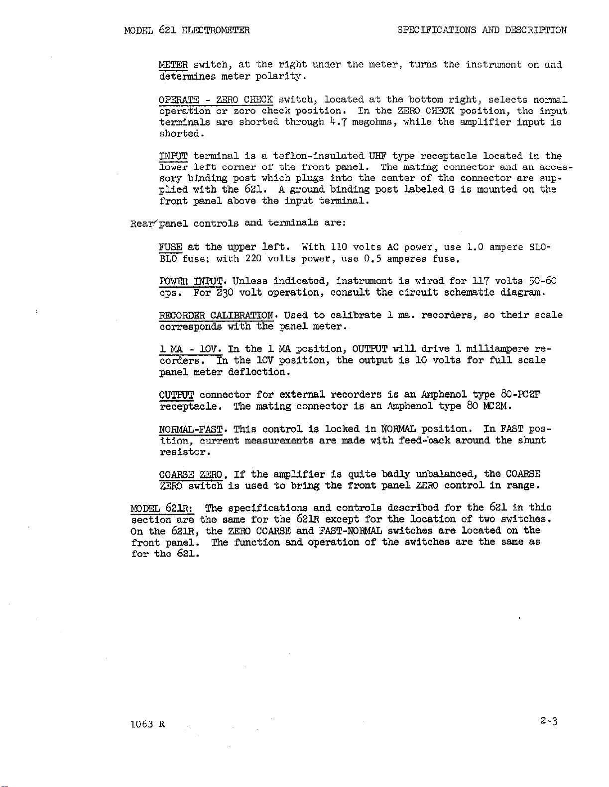
METER switch, at the right under the meter, turns the instrument on and
determines meter polarity.
OPERATE - ZERO CHECK switch, located at the bottom right, selects normal
operation or zero check position.
terminals are shorted through 4.7 megohms,
In the ZERO CHECK position, the input
while the amplifier input is
shorted.
INPUT terminal is a teflon-insulated UHF type receptacle located in the
m left corner of the front panel.
The mating connector and an acces-
sory binding post which plugs into the center of the connector are sup-
plied with the 621.
A ground binding post labeled G is mounted on the
front panel above the input terminal.
Reafpanel controls and terminals are:
FUSE at the upper left. With 110 volts AC power, use 1.0 ampere SLOmfuse: with '220 volts power, use 0.5 amperes fuse.
FOWER INNT. Unless indicated, instrument is wired for ll'i' volts 50-60
cps.
For 230 volt operation, consult the circuit schematic diagram.
RECORDER CALIEPXCION. Used to calibrate 1 ma. recorders, so their scale
corresponds with the panel meter.
1MA - 1OV. In the 1MA position, OUTPUT will drive 1 milliampere recorders.
In the 1OV position, the output is 10 volts for full scale
panel meter deflection.
OUTFUT connector for external recorders is an Amphenol type 80-FC2F
receptacle.
The mating connector is an Amphenol type 80 MC2M.
NORMAL-FAST. This control is locked in NORMAL position. In FAST pos-
ition, current measurements are made with feed-back around the shunt
resistor.
COARSE ZERO. If the amplifier is quite badly unbalanced, the COARSE
ZERO switch is used to bring the front panel ZERO control in range.
ML)DEL 621~:
The specifications and controls described for the 621 in this
section are the same for the 621~ except for the location of two switches.
On the 621.13, the ZERO COARSE and FAST-JYQRMAL switches are located on the
front panel.
The function and operation of the switches are the same as
for the 621.
1063 R
2-3
Page 9

SECTION III - CIRCUIT DISCUSSION
The basic element of the Model 621, is a highly accurate, stable dc volt;;;;$g$- gpi
scale sensitivity of 100 millivolts and an input Impedance
ohm shunted by 30 micro-microfarads. Amperes and ohms
are measured by the use of resistance standards. The various connections
necessary for amperes and ohms measurements will be discussed following the
detailed description of the amplifier.
A. VOL!UGTER
Refer to DR 13515-D at the ,rear of the manual.
The amplifier proper consists
of V-land V-2. V-3 is a cathode
follower which drives the amplifier
at the same instantaneous potential
as the Input signal. In other words
the neutral or ground terminal of
-4
lNP"T
0
the amplifier is not grounded to
the chassis but is attached either
directly or through divider R-201
through R-207 to the output cathode
follower. Figure 621-1 shows this
diagramatically. The amplifier A
is driven by the cathode follower.
If it is desired to have unity gain,
the amplifier is connected directly
OUTPUT DROUND
to the cathode. To increase the
voltage gain,, a fraction of the output voltage rather than all of it
FIGURE 621-i
is fed back.
The purpose of this arrangement is to allow the input to accept relatively
large input voltages without use of input dividers, which are neither stable
nor accurate at high impedance.
Consequently, the Model 621 will a~ce~~-t. 100
volts without the use of input dividers, preserving the high input impedance
and accuracy of the amplifier. Accessory probes are available for extending
the voltage range at reduced input resistance and accuracy.
Since the amplifier proper is driven by the cathode follower, the plus and
minus 220 volt supplies for the cathode follower are referred to input ground
while the +150 and +105 volt, and -150 volt supplies for the amplifier are
referred to amplifier ground which is "floating". In subsequent discussion,
reference will be made to the amplifier ground as "floating ground" and to
cathode follower ground as "output ground".
The amplifier input consists of a 5886 electrometer tube. The filament is
operated through a dropping resistor network from the regulated B plus supply.
The control grid of V-l, the electrometer tube, is protected by R-102, a 4.7
megohra resistor, by-passed for high frequencies by C-102. The input switch,
S-2 connects the grid of V-l to the Input terminal on the OPERATE position
and connects it to ground, through the 4.7 megohm protective resistor, on
zm?l cm.
The belance controls function by adjusting the dc voltages of the electrometer
tube screen and the grid.of V-2.
V-2 fo- an ordinary differential amplifier and the output is taken into V-3
the output cathode follower.
III - 1
Page 10

CIRCUIT DISCUSSION
iXJDSL
621
ELECTROIJ~ET~
The voltmeter sensitivity is determined by the fraction of the cathode fol-
lower voltage fed back via the divider, R-201through R-207.
The OUTFUT Is derived directly from the &M6 cathode. If the output switch
(s-6) is set at 10 V, R-127 is set across the output terminals.
If the output switch is set at lma, R-l27 in combination with R-l28 are used to pmvide enough series resistance so that lmillismpere flows into the recorder
terminals.
R-128 calibrates the recorder on all ranges.
The feedback loop is stabilized against oscillation by C-ll.6 together with
R-lL2.
The gain is kept high enough so that there is a large feedback factor
on all ranges, but the gain is not allowed to become high enough to cause
oscillation.
B. AMMETER
Grid current of the input electrometer tube fixes the minimum current that
w be
2 x lo-
asured.
Yt
amperes.
The Model 621 grid current will usually be less than
(1) Shunt Resistor Method (NORMAL) In
CUT
FIGURE 3. Normal Ameter Operation Schematic
Feedback Method (FAST)- In the vol
the normal operating connection
as shown in Figure 3 current
Is measured by placing a resistor
across the inpt terminals and
measuring the voltage drop. The
voltage drop is selected by the
MULTIPLIER switch; the setting
is the input voltage drop for
full-scale meter deflection.
,tmeter discussion above, float*
grouud has been driven by the cathode
follower audoutputgrouudhas been
conuected,to the low impedance side
of the input connector. In the FAST
connystion, shown in Figure 4,
the amplifier ground is connected
to the low impedance side of the
input; the cathode follower ground
floats, and negative feedback is
applied through the shunt resistor.
FIGURE 4. Fast Anrmeter Operation Schenatic
3-2
0762
Page 11

mm
621
ELECTROMETER
In the Model 621, it Is possible to use this connectlon.with currents of
100 mic~res or less. To change the connection, remove the lock from
the NORMAL-FAST switch at the bottom of the rear panel end change it to the
FAS'J! position.
(a) The effect of input capacity is Largely neutralized, that is, the
time constant of the input and cable capacity and the shunt resistor
used will be decreased at least I.00 times as compared to the NORMAL
conuection, corresponding to a EC-fold increase in response speed.
(b) !Che input drop will be reduced at least 100 times.
If Figure 4 is again consulted it wilLbe seen that this connection converts the 621 into an operational amplifier wfth a resistor from the output to
the Input.
The input cannot be shorted since this will remove the feedback.
!Che internal impedance of the current source being measured should
i
H
not be less than about one-tenth of the value of the feedback resistor
used fbr measurement.
(c) This connection should not be used for measuring the leakage cur-
rent of capacitors since the connection of a capecitor to the input
causes the circuit to be transformed into a differentiator with the
resultant extreme sensititity to very small voltage transients. For
this measurement the NORMAL should be used.
The advantages of this connection exe:
Therefore, the following cautions apply:
CIRCUIT DISCUSSION
c. o-
(1) Normal Method.
FIGURE 5.
Operation Schematic.
the amplifier ground keeps It at virtually the seeae potential as the input
grid regardless of the input voltage, the voltage across the current source
resistor cannot chage.
source regardless of the input voltage.
Normal Ohrmneter
TheModel621empl.oys a linear scale to provide a
megokmrmeter of high acouracy.
Th; linear ohms s&e is achieved
by supplying a constantcurrentto
the sample and measuring the voltage
drop across it. The method used
to obtain a constant current, is
illustrated In Figure 5. The
ground connections are in the NOR-
MAL position, that is, the smplifier
ground is driven and the cathodefollower ground is attached to the
input ground. The voltage source
is only one volt. However, it is
attached between floating ground
and the grid of the voltmeter while,
as before, the test sample is attached between input ground and the
voltmeter grid. Since feedback to
Therefore, this arrangement provides a true current
(2)
Use of Elxternal Voltage Supply. With the constant current method
of measuringresistance, the voltage across the unknown may not be arbitrar-
ily selected, and the time of measuring capacitor leakage tends to be log,
since constant-current cbarglng~is slower than the exponential charge available with an RC circuit.
Page 12

CIRCUIT DISCUSSION
MODEL 621 ELD.X'ROI.ISTER
Due to these facts, it may be desirable to use an external voltage supply
end measure the leakage current on the AMPEXFS scale (NOFA4.L operation).
The unknown is connected between the input terminal of the electrometer and
the source of voltage. This is
shown in Figure 6. If the ap-
plied voltage is large compared to
the voltage drop across the electro-
meter (so that the voltage across
the ssmple is substantially the applied voltage) the resistance is
simply equal to the voltage applied
EXTERNAL
VOLTAQL
T
divided by the current measured.
If the voltage drop is an appreci-
able fraction of the applied voltage,
FIGURF 6. Obnmeter with External
Voltage Supply Schematic
the resistance equals the voltagelr
applied minus the input drop divided
by the current measured. It will
be rarely necessary to correct for
to.the excellent voltage sensltivit
the input drop of the electrometer due
g of the MO&J 621.
It is advisable to use the NORMAL micro-microammeter conuection for the measurement of leakage resistance of capacitors in this manner, since instability is
likely to occur using the FAST connection.
However, in cases whsre the capacity
shunted across the ssmple is small, it wi.lJ. be possible to realize a consider-
able increase in speed of response by utilizing the FAST connection.
Some precautions are recommended when testing capacitors. De sure that capac-
itors have discharged before
removing
from test circuit. With the 621 input
switch on ZEIiC CHECK, the input is shorted to ground through 4.7 megohms, pro-
viding a discharge path for the capacitor.
It should be further noted that capacitor measurement Is likely to be a slow
process in any case due to the fact that It may take considerable time for the
molecular orientation of the dielectric to take place at the testing potential.
It may take minutes or even hours in some cases to achieve a stable reading.
3-4
0762
Page 13

MDLEL 621 ELE.?~ROMETER
SJE!?ION IV - O-ON
OPERATION
A.
mARING THE INSTRUMENT
FOR OPERATION
(1) Connect to power line of proper voltage and frequency. Unless other-
wise indicated at resr of i$rstrumsnt, the Model 621 is wired for 100 to
130 volts 50 to 60 cps.
If it is dssirsd to operate on 200 to 260~volts
50 to 60 cps, consult DR 13515-D at rear of the manual for instructions.
(2) Set controls as follows:
WLTIPLIER:
P,ANGE SWIl'X:
OPERATE SWIEE mm CrnK
INRIT TEFtMmAL:
Shield with Cap.
(3) Tnrn the METER stitch to meter +. Ths instrument should come to
zero In approximately 30 seconds.
Final stability within drift spec-
ifications till not be achieved for 2 hours.
(4) Rotate the m switch toward the high sensitivity end, adjust-
ing ZERO as required.
If it Is wssible to zero the meter with the front
panel ZERO control, use COARSE BAL control on rear panel to bring the in-
strument within range of the ZBRO contml.
(5) Connect leads as required for measurement. If high impedance is in-
volved, the input should be shielded using a coaxial connection or shielded
enclosure. The various accessories for the Model 6211~~ be used.
If the impedance is low and leads can be kept short, the binding post
adapter furnished with the instrumsnt may be used.
The Keitbley Model61ClA Shielded Test Probe, will suffice for most measure-
merits.
B.
klBASURlXG~LTPC;E
Place RANGE switchat VOLTS. TurnMULTIPLIER switch to expected sensitiv-
ity and check meter zero. Move OPERATE switch up to OPERATE and read.
the sensitivity of the instrumsnt is increased, recheck the zero setting.
For voltages greater than 100 volts,
use
the Model 610g~, lo:1 Divider Probe
or the k@dsl6103A, 1OOO:l Divider Probe, and measure as above.
c. MEASURING CURRENT
(1) NORMAL method
Turn RANGE stitch to desired AMPERES range. Make sure the switch at the
rear of the instroment is on the NORMAL position.
to input.
PLIER gives the full scale range.
and then read,unknown current.
The product of the reading on the RANGE switch and the MULTI-
Check zero first with OPERATE switch
The fbll scale voltage drop across the
Connect current source
instrument is the setting of the M!JL!lPLIlB.
If
(2) FASTmethod
Proceed as,above, except move the FAST-NORMAL switch at the rear of the
instrument to the FAST position.
The input drop isnow negligible and
the speed of response is increased approximately I.00 times. However, ob-
serve the following cautions:
0762
4-l
Page 14

OPEFKCION
MODEL 621 ELECTROME~R
Use only the input switch to check zero; K) NOT SHORT INRTT.
b"
The low side of the output is no longer grounded. Therefore,
I{
if the instrument is being used with an output recorder, the recorder
must not be grounded to the case of the 621.
(c) Do not use this position for the measurement of capacitor
leakages.
D. MEASURING RESISTANCE
- -2
(1) NORMAL method (lo5 ohms to 10~ ohms full scale).
Tnrn RANGE switch to desired OHMS range. Make sure that NORMAL-FAST switch
is in the NORMAL position.
after OPERATE switch has been moved to ZF&O CHECK.
Connect resistance sample to be measured only
Do not open-circuit
instrument when on OHMS, since the input will develop a large voltage due
to its constant current characteristic. However, if the sample is first
connected and then the OPERATE switch is moved to OPEFXTE, the full scale
input voltage till be the setting of the WLTIPLIEFi.
Before reading OHMS, turn RANGE switch to the approximate range of the
unlcnown resistance. By manipulating the MJLQIPIJFZi end the RANGE switch,
the sample can be tested at a tumioer of test potentials, if desired.
The full-scale ohms range is the R&GE switch setting times the MULTIPLIER.
(2) .Wl%RNALVCLTAoE method.
Any external voltage mey be used.
The unknown is connected between the
test potential and the IIWJT terminal of the electrometer. The current
is then measured, using the XXMAL or FAST method., and the resistance cal-
culated..
Proceed a8 follow:
a
Turn input switch to ZERO '.X%X.
b Connect unknown between INWT terminal and source of potential,
iI
A stitch should be connected in the high vdtage line so that when
the ssmple is disconnected from the potential, the low impedance end
of the sample is grounded.
FAST-NORMAL switch shouldbe atIK%ML
z
Apply potential to sample before swltchlng to OPERATE.
(1
start
the RUiGE switch at low current sensitivities and advance the sensitivity until a reading is obtained.
If the potential applied is at least lCO.times the full scale anrmeter
dmp (MULTIPLIER setting), the resistance is equal to:
4-2
If the potential applied is not large compared to the ammeter drop,
the resistance is equal to:
(e) If it is r
ssible
to operate on FAST micro-micmanmmter, the
input drop nee not be considered in the calculation.
0702
Page 15

MODEL 621 ELECTROMETER
E. USING EXTERNAL INDICATORS
The Model 621 output will drive l-milliampere recorders and servo rebalance re-
corders, as well as higher impedance instruments such as panrecorder amplifiers
and oscilloscopes.
OPERATION
(1) lo-volt outout.
OUTPUT Receptacle.
to 10 V.
tion on any range.
range.
permissible load across the output terminals in this mode is one megohm. The
METER Switch does not reverse the output polarity.
(2) l-Milliampere Output.
Angus, General Electric or Texas Instrument Rectiriter, to the OUTPUT Receptacle.
Pin no. 1 is the positive terminal.
is approximately 1 milliampere for full-scale meter deflection on any range.
For exact output,
for full-scale deflection.
reads full scale. Check the recorder and meter zero and repeat adjustment if
necessary.
(3) For servo rebalance recorders,
Receptacle. See Figure 1A.
Control to trim the output for full-scale recorder deflection,
the same as for current outputs.
The Model 621 output is now 10 volts dc for full-scale meter deflec-
Maximum output amplitude is approximately 10 volts peak-to-peak. Maximum
The Model 621 may be used with the FEEDBACK Switch in FAST
position with other instruments. However, make sure there
is no common ground between the Electrometer case and the
other instrument.
The METER Switch does not reverse the output polarity.
Connect oscilloscopes and pen recorder amplifiers to the
Pin no. 1 is the positive terminal. Set the Output Switch
The frequency response (r3 db) is dc to 200 cps on any
Connect l-milliampere instruments, such as Esterline
Set the Output Switch to 1 MA.
adjust the meter on the’O.l-volt range with the ZERO Control
Then adjust the 1 MA CAL Control until the recorder
use a divider across the Model 621 OUTPUT
Set the Output Switch to 1 MA.
Use the 1 MA CAL
The output
Operation is
50-millivolt output
1
FIGURE 1A.
driving, 50 and lOO-millivolt recorders.
Divider Circuits Across Model 621 Cutput.
1 kn
loo-UN
100 n
lOO-millivolt output
The dividers are for
Use 1% resistors in the dividers.
Recorder
:
4-3
Page 16

OPERATION
MODEL 621 ELECTROMETER
(4) When the FEEDBACK Switch is in the NORMAL position, the negative side of
the output terminal is grounded to the instrument case.
Therefore, no difficulty will be experienced using oscilLoscopes and recorders with the Model 621
set for normal operation.
If this is used,
make sure there is no common ground between the recorder or
In FAST position, however, neither side is grounded.
oscilLoscope and the Model 621 case.
CURRENT SOURCF,. The Model 621 can be used as a current source from 10s6 to
F.
10-10 ampere. Follow these procedures:
(1) Set the FEEDBACK Switch to NORMAL, the Range Switch to OHMS and the METER
Switch to + or -.
(2) The current supplied at the INPUT Receptacle is the reciprocal of the OHMS
Setting on the Range Switch. (For example, LO9 OHMS indicates 10-g ampere
current at the INPUT Receptacle.)
(3) The l%ltiplier Switch does not affect the current at the INPUT Receptacle.
It does affect the maximum input voltage drop, which is equal to the Multiplier
Switch setting.
For accurate output current,
check the meter zero on the l-
volt position of the tiltiplier Switch.
G. STATIC CHARGE MEASUREMRiTQ: The instrument is zeroed and the RANGE Switch
placed on VOLTS.
The voltage sensitivity is perhaps placed at 10 or 30 volts
full scale. The charged object is then brought near the uncovered, unshielded
.inpClt connector of the 621. Depending on the distance between the charge and
the instrument, a voltage will be induced on the input terminaL and can be read
on the panel meter. The instrument zero should be checked frequently since
accumulation. of charge due to the electrometer tube nrid current will cauee a
slow drift of input voltage.
Connecting a capacitor across the input reduces the drift due to grid current and
also the sensitivity to charge. An electrode connected to the INPUT terminal
which increases the capacitance between the INPUT terminal and the charged object
will increase the sensitivity to charges.
4-4
Page 17

AcCBSSORIES
SECTION V - ACCESSORIES
A. MODEL dlOlA, ACCFSSOWPROBE:
The Model 6lUprobe consists of an input connector, 3 feet of low noise
cable and a shielded probe head.
nection to the electrometer input.
MODEL 6102~, 1O:l DIVIDER PROBE:
B.
The Model 610~~ divider probe is intended for general purpose measurements
where an extension of the upper voltage range of the
division ratio is 1O:l correct to 1% and the probe input resistance'is
OhlW.
C.
The Model 610.0~ probe is intended for very high voltage measurements at high
impedance. The Qvision ratio is 1OOO:l correct to 3% and the probe input
resistance is 10 ohms. The probe is supplied with a mating connector and
3 feet of cable.
The probe is supplied with a mating connector and 3 feet of cable.
MODEL 61oy, 1OOO:l DIVIDER PfEoBB:
Its purpose is to allow convenient con-
621
is desired.
melO
10
MODEL 6104, TBST SHIELD:
D.
The Model 6104 Test Shield is intended for use in making measurements where
complete shielding of the component under test is required.
minals are provided for either grounded tests, or a test requiring an external voltage source.
ORDERING !LCCESSORIES:
E.
The accessories listed above facilitate measurements and extend the range of
the 621 Electrometer.
Instruments field representative or
Order Service Department
Keitbley Instruments, Inc.
28775 Aurora Road
Cleveland, Ohio
To order the accessories, contact the nearest Keithley
44139
External ter-
0767R
5-l
Page 18

WDEL
621
ELFU!ROMSl?XR
MAINTENANCE
SECTION VI - MAINTENANCE
No periodic nntintenance is required. There are no internal batteries.
The calibration of the vultmeter is set by R-130 located on the P.C. Board.
This is set at the factory and should not require adjustment. If recalibration is performed, an accurate voltage source should be used.
A. TROUBLE SHooTINa
The circuit is completely described in Section III. Study of that section
will facilitate any trouble shooting.
The most usual trouble encountered is that on the mst sensitive voltage
range, with in input shorted, it is not possible to bring the meter pointer
to zem. However, before assuming that the instrument is at fault make sure
that resetting the COARSE BAL control at the rear
of
the instrument will not
bring the instrument back into balance. If' this does not work remove the
instrumsnt case, by removing the 3 screws on each side of the cover to gain
access to all circuitry,
621;
reeve 2 screws and lift off cover,
621~.
Follow this procedure:
(1) Check for preseAce of regulated B-plus voltage by switching to
meter t and checking at pin 1 of
V-3
for +150 volts ?lO$; pin 3 of
V-2 for +1.08 volts 20%; and pin 2 of V-4 for -150 volts 210%.
(2)
If correct voltage is present, check the plus and minus 220 volt
supplies.which supply ths output cathode follower. The plus voltage is
present on pin 9 of V-3.
The minus voltage rm%y be obtained from the
bottom of the KlOK~cathode resistor of V-3. It is a 2 watt power re-
sistor located on the printed cirouit'board. If this voltage is not
correct consult the schematic and trouble shoot the supply in the usual
manner.
(3) If no defects are found so far, proceed by shorting floating ground
to output ground to remove the negative feedback. This is most conven-
iently accqnpliahed by shorting the two ends of the FAST-NOW switch
on the rear panel.
sensitive and in operating the ZEXiO control, the meter till
ficult to hold on scale.
In this conition the instrumsnt will become very
be
very
However, the indication that the circuit is
dif-
operating satisfactorily is that it is possible to swing the voltage
through the correct operating point as Indicated on the voltage-resistance
diagram.
Now with the MULU?IPLIEKat 0.1 vults, proceed to check the operating points
of the tube electrodes.
Regardless of the condition of the amplifier balance, the filament, cath-
ode and screen potentials, except for the screen of V-l, should be reason-
ably close to the values on the circuit diagrsm. The ptite and grid
potentials will, however, depend on the setting of the ZEF0 contml.
However, if it is possible to swing the voltage through the correct value
it ,may be assumed that the stage is working. Proceed in this maaner unt$lthepoint is foundwhereths voltage cannot be swung'throughthe
value marked on the diagram.
to find the fault.
First check the tube involved and then check the
At this point it will
be
relatively easy
components.
Page 19

MAINTENANCE
Miscellaneous Troubles:
MODEL
621 ELDXROMTI?ER
TROUBLS
Excessive grid
current
Excessive drift
Excessive micm-
phonics
Instrument does
not zero
The Voltage-Resistance Diagram shows the proper positioning for inserting
the electrometer tubes.
where the leads emerge when inserting the tubes.
Make certain fingers do not touch the glass base
Defective electro-
Power supply not
Defective electro-
See section above
CAUSE
meter tube
regubted
meter tube
FtlN3DY
Replace V-l
Check OB2
stability
Replace V-l
See section
above
6-2 0762
Page 20

MODEL
621
ELECTROMETER
RFPLACF&lLE PARTS LIST
HOW M ORDER PARTS
Order component parts directly fmm the manufacturer or from Keithley Instrumats Inc. Order all structural parts fmm Keithley.
!the Replaceable parts list gives the code nlrmber of the component's manufacturer
in the MFO. CODE columu.
The name and,address of the manufacturer having the
cods number is listed in the Manufacturers' Code Definitions Table Qvnediately
following the Replaceable Parts List.
When ordering fmm the manufacturer, pur-
chase only quality components meeting the listed specifications.
When ordering from Keithley Instrumsnts, give a description of the part being
ordered, the circuit designation, the Keithley part number, the instrument model
number, and the instrwnsnt serial number. Send to:
Order Service Department
Keithley Instruments, Inc.
28775
Cleveland, Ohio
Aurora Road
44139
Cer
CerV
Camp
con&w
DCb
LIST OF SYMBOLS AND A2BRJXUTIORS
Amperes
Ceramic Disc
n OhUl
P
Pica (lO-12)
Cers&c Variable PST Polystyrene Tubular
Composition
Composition Variable
Deposited Carbon
Electmlytic Can
R Resistor
SW Switch
w
Micro (100-G)
Electrolytic Tubular
volts
Watt
Wire Wound
Wire Wound Variable
Farad
Kilo
Miui
(lo3
(y-3)
V
Var Variable
)
Gw
!dwrar
Mega (10 )
w-
0767R
6-3
Page 21

REPLACEABLE PARTS LIST -MODEL
621
Circuit
Desig.
Cl01
cl.02
Cl03
Cl04
Cl05
V&Lue
.OOl pf
.OOl Hf
4,7 pf
.0022 pf
.Ol pf
~1.06
:%
clog
cllo
clll
cll2
Cl13
Cl14
c=5
cu6 .0047 pf
CD7
cu8
.OOl pf
.Ol pf
Rating rype
Cer
22 ;
500 v
E 1:
1000 v
1000 v
500 v
500 v
500 v
5oov
1000 v
1000 v
350 v
350 v
z: ::
600 v
Cer
Poly
Cer
Cer
Cer
Cer
ETB Dual Section
ETB Dual Section
t
!Zl!B (Dual Section)
El?3 (Dual Section)
Cer
Cer
ETB
Em
Cer.
Cer
Cer
Mfg.
Code
72982
iv82
71590
72982
,14655
3;;
14655
56289
56289
Keithley
Part No.
c22-.OOl
c22-.OOl
C138-4.JP
c22-.0022
c22-.Ol
~64-470
~64-470
c68-20/20
c68-20/20
c68-20/20
c68-20/20
c64-47
c64-47"
8
c32-4O
c32-4O
czz-.0047
c22-
.OOl
c22-.Ol
Circuit
Desig.
D-l
D-2
D-3
D-4
D-5
n-6
D-7
I-l
I-Z
M-l
Description
Rectifier
Rectifier
Rectifier
Rectifier
Rectifier
Rectifier
Rectifier
Fuse,
Meter, 1 ma
0.5 A]3 AG
MISCEILNWXJS PAFZS
Ep;;
u3255
W3255
m3255
UT3255
J-N3253
Mfg. Code
02735
02735
02735
02735
02735
02735
02735
75915
75915
72765
08806
80164
Keithley
Part No.
RF-17
RF-17
m-17
RF-17
RF-17
RF-17
RF-20
m-4
Fu-10
PL-4
PL-1
m-35
6-4
0267R
Page 22

REPLACEAIGE PARTS LIST - MODEL 621
RJ!xrsMRs
Circuit
Deaig . Value
RlOl
R102
R103
R104
R105
R106
R107
RlO8
RlOg
XXI.0
9m
lK.fl
500 n
15 K+Q
250 .a
RlLl.
Rll2
R=3
Rll4
R=-5
R116
RlJ-7
Z-70 i-2
150 m
Rll8
Ru9
RX?0
E-lm
12.5 KS-2
Rating Type
COmp
Eb
DCb
conlpv
ww
DCb 01661
Ccb
War
IYZb
CCb
COmp
cow
Camp
camp
camp
camp
cow
ww
.yw
m-g.
CO&
01121
oll.21
00327
00327
80164
91637
Keithley
Part NO.
Rl-4.716
Rl-4.7M
Rl2-g6K
RlZ-10M
RPl2-20K
Rl+l-gK
Rl.2-lK
00327
80164
01661
01661
Rl2-500
Rp3-15K
~12-250
R12-200
oll21 Rl-1OK
Oll.21
44655
Oll21
44655
on21
oll21
R3-3.3
R3-100K
R2-100
Rl-270
Rl-150K
R3-3.F
R5-5K
2g
R5-l2.5K
R121
R122
~123
~124
~125
R131
~132
RI33
R134
R201
R202
~203
~204
R205
~206
R207
~208
2m
2.2 Krl
5m
220 KS-2
lm-2
1.5 im
9.1 m
15 K0
500 n
2Ksl
47 IQ-2
23.3 KQ
loo Iu-8
1K.Q
91 s-l
273 0
910 a
2730 fi
g.1Krl
27.3 KQ
?KF
liw
ww
Camp
Eb
LXb
LCb
wwvar
DZb
CbV
Ccb
IXlb
camp
Deb
DCb
Ccb
IXJb
LXb
Lcb
KCb
DCb
Ccb
R4-2K
~~~
37942
44655
0032'7
01661
~5-2.2~
m3-5K
Rl-220K
RI&IN
RI&1.5M
RlZ-9.X
zz
00327
71450
01661
00327
*3-1%
Rl2-500
Pm.2-2K
Rl2-47K
Rl2-23.X
oll.21 Rl-100K
01661 RIZ-lK
01661
Rl2-91
R12-273
3%
00327
00327
Rl2-glC
Rl2-2730
RIZ-g.lK
01661
E:Z"
3z
R12-6K
0267R
6-5
Page 23

RFZXACF.ABLE PARm LIST -MODEL 621
Resistors (Cont'd)
Circuit
Lhsig .
R301
xi302
8303
R304
R3o5
circuit
Desig.
S-1 Switch, Range
s-2 Switch, Operate
s-3
s-4
s-5
s-6
T-l (Model
T-1 (Model
Value
1010 n
109 n
100 MO
10 M&-l
li%C
621)
621~)
Description
Switch, Meter
Switch, Multiplier
Switch, Slide, DPDT
Switch, Slide, DPDT
Transformer, Power
Transformer, Power
Rating
2%
2%
l$, 2 w
l%,
l%, hw
MISCELLANEQUS PARTS
112
w
Mfg.
me
Glass D3b
Glass TCb
CCb 01661
Ccb
D3b
Mfg. Code
Code
63060
63060
00327
00327
80164
E::
80164
79727
79727
80164
ml64
Keithley
Part No.
R20-1010
R20-109
R14-100M
RlZ-10M
RlZ-lM
Keithley
Part No.
SW-103
SW-llo
SW-113
W-100(3
SW-45
SW-45
~~~23
mi57
VACUUM !lxJBEs
circuit
Desig. Tube Number
V-l
v-2
v-3
v-4
v-5
v-6
5886-5
6BH8
6c~6
OA2 86684
6627
6626
Mfg. Code
801.64
85599
80368
86684
86684
Keithley
Part NO.
gw3g-5”
w-Gad.6
EX-OA2
m-6627
EV-6626
6-6
0267R
Page 24

MODEL 621 ELECTROMETER
MANUFACTURERS' CODE DEFINITIONS
00327
00686
01121
01661
02735
08806
14655
37942
44655
56289
we1wyn International, Inc.
Cleveland, Ohio
Film Capacitors, Inc.
New York, N. Y.
Allen-Bradley Corp.
Milwaukee, Wis.
Wilrite Products, Inc.
Cleveland, Ohio
Radio Corp. of America
~omercial Receiving Tube and
Semiconductor Division
Somerville, N. J.
Miniature Lamp Dept.
G. E. Co.
Cleveland, Ohio
Cornell-Dubilier Electric Corp.
Newark, N. J.
Mallory, P. R., and Co., Inc.
Indianapolis, Ind.
Ohmite Mfg. Co.
Skokie, Ill.
Sprague Electric Co.
North Adams, Mass.
71590
72765
72982
73445
75915
79727
80164
80368
85599
86684
Centralab Division of
Globe-Union, Inc.
Milwaukee, Wis.
Drake Mfg. Co.
Chicago, Ill.
Gudeman Co.
Chicago, Ill.
Amperex Electronic Co. Division of
North American Philips Co., Inc.
HicksvFlle, N. Y.
Littelfuse, Inc.
,Des Plaines, Ill.
Continental-Wirt Electronics Corp.
Philadelphia, Pa.
Keithley Instruments, Inc.
Cleveland, Ohio
Sylvania Electric Products, Inc.
New York, N. Y.
Tube Department G. E. Co.
Schenectady, N. Y.
Radio Corp. of America
Electronic Components and Devices
Harrison, N. .J.
63060
63743
71450
1164R
victoreen Instrument co.
Cleveland, Ohio
Ward Leonard Electric CO.
Mount Vernon, N. Y.
CTS Corp.
Elkhart, Ind.
91637
95333
Dale Electronics, Inc.
Columbus, Nebr.
Central Transformer Co., Inc.
Chicago, Ill.
6-7
Page 25

6
Page 26

L
-
Page 27

REPAIR AND CALIBRATION FORM
repair or calibration, please fill out this form and return it with your instrument to:
For
Sales Service Department
Keithley Instruments, Inc. R-
28775 Aurora Road Do not write in this space.
Cleveland, Ohio 44139
l
Telephone
Address
city
Model No.
Calibration Report Desired
0 Report of Calibration Certified
Traceable to N.B.S.
a Certificate of Compliance
0 Nofie
(for details, see reverse side of this form)
- Intermittant
f) Other (such as line transients,
line variations, etc.)
OF
OF
User’s Name
company
DiViSiOIl
Date
1.
Reason for Return 2.
0 Repair and Recalibration
0 Recalibration only (No report, except
as specified in item 4 on reverse)* 0 Calibration Report
*If repairs are necessary to meet speci-
fications, they will be in addition to
the calibration.
3. To help repair the instrument, briefly describe the problem:
4. 1s the problem - Constant
Under what conditions does the problem occur:
a) Control setting e) Line voltage
b) Approx. Temperature
c) Approx. Temperature variation
d) Approx. Humidity (high, medium, low)
state
Serial No.
Ext.
Zip
5. Please draw a block diagram of the system using the Keithley. List any other pertinent data which can help in the repair. Include charts or other data if available.
Signal source
Source Impedance
Readout Device:
q Recorder
27 Oscilloscope
2
- Other
a None
Lengths & Types of Connecting Cables
6. What repairs or modifications have been made on this instrument which are not on file
with the Keithley Repair Department?
7. Please enclose any other pertinent data and charts which you feel might help the
Repair and Calibration Department
Signature Title
1267
Page 28

CALIBRATIONS ~AVAILABLE AT KEITBLEY INSTRUMENTS.
Lift~ed ~and~~defined ~below dare the -four type~s ~bf calibrations~ and their associated
~~~ report:~formats which are ~pres:ently ~eva~ilable-ate ~Keithley Instruments.
They fall
~~ the following categor~ies :
~1. ReRort~ of ~Ca~libration Certifia~d Traceable to the ~National Bureau of
Standards
2~. Calibration-Report
~3. Certificate,of Compliance
4; ‘Recalibration~
All calibrationand~certificati~on~performed ~by Keithley Instruments is in accord
with MIL-C-4566&
Prices, ~shown ~below 8re in ~sddition stop ~repalr- charges for any work necessary to place
a~customer’s unit into first classcondition prior to the calibration.
into
 Loading...