

Page 1

MODEL 601 ELECTROMETER
CONTENTS
TABLE OF CONTENTS
Section
1. GENERAL DESCRIPTION .
l-l. General . . .
1-2.
1-3.
Features .
Specifications ,
l-4. Applications . .
1-5.
1-6.
2. OPERATION . . . . .
2-l.
Accessories . .
Equipment Shipped
. . .
Front Panel Controls
and Terminals . . . .
2-2.
Rear Panel Controls
and Terminals . . .
2-3.
2-4.
2-5.
2-6.
Input Connections . . .
Preliminary Procedures
Voltage Measurements .
Off Ground Voltage
Measurements . . . .
2-7.
2-8.
2-9.
2-10.
2-11.
Current Measurements .
Resistance Measurements
Charge Measurements . .
Recorder Outputs . . . . . . 17
Unity Gain Output . . .
3. APPLICATIONS . . . . . . . . . .
3-l.
General . . . : . . . . , .
3-2. current source , . . . . .
3-3. Static Charge Measurements
3-4.
3-5.
Capacitance Measurements .
current Integrator . . . .
3-6. Potentiometric Voltage
Measurements . . . . , .
3-7.
Measuring Diode
Characteristics . . . . ,
3-8.
4.
CIRCUIT DESCRIPTION . . . , .
Peak-Reading Voltmeter . .
4-l. General . . . . . . .
4-2.
4-3.
4-4.
4-5.
4-6.
5.
SERVICING . . . . . . . . .
Voltmeter Opiration , .
Voltmeter Circuit . . .
Ammeter Operation . . .
Ohmmeter Operation . .
Coulombmeter Operation
5-l. General . . . . . . . .
5-2. Servicing Schedule .
5-3.
Parts Replacement , . ,
Page
1
1
1
2
2
4
5
. .
5
. . 6
. . 7
. . 8
. . 9
. . 11
. . 12
. * 14
. . 17
. . 18
* 21
. 21
. 21
. 21
. 21
. 22
. 22
. 22
. 23
25
25
25
26
27
28
29
31
31
31
31
Section
5-4. Troubleshooting . . . .
5-5.
Procedures to Guide
Troubleshooting . . . .
6. CALIBRATION . . . . . . .
6-l.
6-2.
6-3.
6-4.
General . . , . . . . . . .
Calibration Schedule . . .
Grid Current Check . . . . .
DC Amplifier Balance
Adjustment . . . . . . . .
6-5. High-Megohm Resistor
Verification . . . . . . .
6-6. Meter Zero Calibration . .
6-J.
6-8.
7.
ACCESSORIES . . . . . . . .
J-l.
J-2.
J-3.
Accuracy Check . . . , , . .
Drift Check . . . . . . . .
Model 6011 Input Cable . .
Model 1531 Gripping Probe .
Model 6301 Guarded Probe . .
7-4. Model 6012 Triaxial-to-
Coaxial Adapter . . .
7-5. Model 6102A Voltage Divider
Probe , , . . , . , . . .
7-6. Model 6103A Voltage Divider
Probe , . . . . . , . .
J-7.
Model 6104 Test Shield . .
7-8. Model 6105 Resistivity
Adapter . . . . . . . . .~
7-9.
Models 2501 and 2503 Static
Detector Probes , . . . .
J-10.
Rack Mounting . . . , . . .
J-11. Model 6013 pH Electrode
Adapter . . . . . . . .
J-12.
MQdel
370
Recorder . . . . .
\
8.
REPLACEABLE PARTS . . . . . . .
8-1.
8-2.
Replaceable Parts List . . .
How to Order Parts . . . .
Model 601 Replaceable
parts List . . . . . . . ,
Schematic Diagram 194283 .
,*
Change Notice . . . . . . . . .last page
* Yellow Change Notice sheet is included
only for instrument modifications
affecting the instruction manual.
Page
31
31
35
35
35
35
36
36
36
37
38
43
43
43
43
43
44
44
44
45
46
46
47
4,8
51
51
51
52
58
0667R
i
Page 2

GENERAL DESCRIPTION
MODEL 601 ELECTROMETER
-
XGURE 1.
ii
Keithley Instruments Model 601 Electrometer.
9666
Page 3

MODEL 601 ELECTROMETER
GENERAL DESCRIPTION
SBCTION 1.
l-l. GENEXAL.
a. The Keithley Model 601 Electrometer is a versatile battery operated instrument which
measures wide ranges of dc voltages, currents, resistances and charges.
refined dc vacuum tube voltmeter that uses an electrometer tube input to provide greater
than 1014 ohm input resistance.
VTVMs, but Lt can also make many more measurements without loading circuits.
The Electrometer has nine volta e ranges from 0.001 volt full scale to 10 volts,
b.
twenty-eight current ranges from 10'
resistance ranges from 100 ohms full scale to 1013 ohms,
10-12 coulomb full scare to 10-6 coulomb.
The Model 601 offers complete line isolation and excellent off-ground measuring capa-
bi;ity. Up to 1500 volts may be applied between the input low terminal and the case, and
safe operation is
guarding of the high terminal.
The Model 601 employs matched electrometer input tubes followed by three differen-
d.
tial transistor amplifier stages and a transistor output stage.
tive feedback is used for stability and accuracy.
assured
with the case grounded. A three-terminal input allows complete
The Model 601 has all the capabilities of conventional
GENERAL DESCRIPTION
It is a highly
l$
ampere full scale to 0.3 ampere, twenty-three linear
and thirteen charge ranges from
A large amount of nega-
l-2.
hour period after warm-up. During the 2-hour warm-up, zero drift is no more than 2 millivolts after the first hour.
+l volt or fl milliampere for full-scale meter deflection.
25% with 1.4-kilohm recorders. The unity-gain amplifier output is equal to the input
voltage within 50 ppm or 100 inicrovolts, exclusive of zero drift.
&he current is determined by measuring the voltage drop across a resistor shunting the
oxput, or the fast method in which negative feedback is applied through the shunt resis-
tor.
greatly increases the response speed on the low-current ranges.
interruptions for-recharging.
corder output is used.
the panel meter,
FEATURES.
Voltmeter accuracy is *l% of full scale, exclusive of noise and drift.
a.
Zero drift of the Model 601 is 200 microvolts per hour maximum averaged over any 24-
b.
Two amplifier outputs are available. A switch on the rear panel allows either
c.
The-current output is variable
Current measurements can be made by one of two methods: the normal method in which
d.
The former method minimizes noise. The latter method reduces the input drop and
e. The lOOO-hour life of the batteries enables "sage in Long-term experiments without
Battery life is maintained even when the l-milliampere re-
For further convenience, battery condition is readily checked on
056JR
1
Page 4

GENERAL DESCRIPTION
1-3. SPECIFICATIONS.
AS A VOLTMETER:
MODEL 601 ELECTROMETER
RANGE:
ACCURACY:
ZERO DRIFT:
any subsequent 24-hour period,
METER NOISE:
INPUT IMPEDANCE:
.OOl volt full scale to 10 volts in nine lx and 3x ranges.
~1% of full scale on all ranges exclusive of noise and drift.
After l-hour warm-up no more than 2 millivolts in the second hour, and in
the average drift will not exceed 200 microvolts per hour.
Cl0 microvolts maximum with input shorted on most sensitive range.
Greater than 1014 ohms shunted by 20 picofarads. Input resistance may
also be selected in decade steps from 10
AS AN AMMETER:
RANGE:
ACCURACY:
Multiplier Switch setting;
METER NOISE:
GRID CURRENT:
LO-14 ampere full scale to 0.3 ampere in twenty-eight lx and 3x ranges.
*z% of full scale on 0.3 to lo-11 ampere ranges using the smallest available
24% of full scale on 3 x lo-12 to lo-14 ampere ranges.
Less
than i3 x 10'15 ampere.
Less than 2 x LO-l4 ampere.
AS AN OHMMETER:
to
1011 ohms.
RANGE:
ACCUR4CY:
plier Switch setting:
100 ohms full scale to 1013 ohms in twenty-three linear lx and 3x ranges.
23% of full scale on 100 to 108 ohm ran 8 es using the largest available Multi-
;t5% of full scale on 3 x 10 to 1013 ohm ranges.
AS A COULOMBMETER:
RANGE:
ACCURACY:
LO-12 coulomb full scale to lo-6 coulomb in thirteen lx and 3x ranges.
i5% of full scale on all ranges. Drift due to grid current does not exceed
2 x lo-14 coulomb per second.
AS AN AMPLIFIER:
INPUT IMPEDANCE: Greater than 1014 ohms shunted by 20 picofarads. Input resistance may
also be selected in decade steps from 10 to 1011 ohms.
OUTPUTS: Unity-gain output and either voltage or current recorder output.
UNITY-GAIN OUTPUT:
clusive of zero drift.
At dc, output is equal to input within 50 ppm or 100 microvolts, ex-
Up to 0.1 milliampere may be drawn. Output polarity is same as
input polarity
0366R
Page 5

MODEL 601 ELECTROMETER
GENERAL DESCRIPTION
VOLTAGE RECORDER. OUTPUT:
+l volt for full-scale input. Internal resistance is 910 ohms.
Output polarity is opposite input polarity.
Gain:
0.1, 0.33,
Frequency Response (Within 3 db):
etc.
to 1000.
dc to 100 cps at a gain of 1000, rising to 50 kc st
a gain of 3.3, decreasing to 1 kc at a gain of 0.1.
Noise:
Less than 2% rms of full scale at a gain of 1000, decreasing to less than 0.5%
at gains below 10.
CURRENT RECORDER OUTPUT:
il milliampere for full-scale input, variable +5% with 1400-ohm
recorders.
GENERAL:
ISOLATION:
Input low to case: greater than 1010 ohms shunted by 0.0015 microfarad. I*-
put low may be floated up to k1500 volts with respect to case.
POLARITY:
Meter switch selects left-zero (positive or negative) or center-zero scales.
Meter switch does not reverse polarity of outputs.
CONNECTORS: Input:
Teflon-insulated triaxial Dage 33050-l. Lo: binding post. Voltage
or current output: Amphenol 80-PC2F. Unity gain output, case ground: binding posts.
BATTERY CHECK:
BATTERIES:
E42N or HG42R).
DIMENSIONS, WEIGHT:
Condition of all batteries may be checked with front panel controls.
Four 2N6 (or 246, VS305 or NEDA 1602); three TR286 (or E286); two RM42R (or
1000 hours battery life.
10-l/2 inches high x 6-5/b inches wide x 10 inches deep; net weight,
14 pounds.
ACCESSORIES SUPPLIED:
Model 6011 Input Cable; mating output connector.
l-4. APPLICATIONS.
Voltmeter applications include directly measuring potentials across pH electrodes,
a.
piezoelectric crystals, capacitors,
electro-chemical cells and biological membranes.
The Model 601 is also useful as a null detector with potentiometers or bridges in high im-
pedance applications.
As a picoammeter the Model 601 can br used with photomultiplier tubes, flame and
b.
beta ray ionization detectors,
lithium ion drift detectors and gas chromatographs.
It is
also useful in nuclear studies , plasma physics and vacuum research.
c. As an ohmmeter the Electrometer is ideal for measuring insulation resistance and
resistor voltage coefficients.
since the Model 601 low terminal can be isolated from case ground.
It is useful for measuring "in circuit" resistances,
Volume and surface re-
sistivities can be measured with the Model 601 and the Model 6105 Resistivity Adapter.
d.
0366R
In addition to measuring charge directly
other coulombmeter uses are measuring
3
Page 6

GENERAL DESCRIPTION
MODEL 601 ELECTROMETER
charge current over a period and obtaining integral curves of time varying currents. The
Electrometer can also be used as a charge amplifier to measure piezoelectric crystal outputs.
l-5.
ACCESSORIES.
(Also see Section 7).
a. Model 6011 Input Cable has 30 inches of low noise triaxFa1 cable with mating triax-
ial input connector and three alligator clips.
Model 6013 pH Electrode Adapter has a Z-foot cable and triaxial connector and accepts
b.
Leed
& Northrop and Beckman pH electrode connectors.
The Adapter allows accurate and con-
venient pH potential measurements with the Model 601.
c. Model 6301 is a high impedance guarded probe with a 3-foot connecting triaxial
cable that allows measurements to be made more conveniently.
lation resistance of over 1014 ohms.
Using the Probe does not effect any Model 601
The Model 6301 has an insu-
specifications.
Model 1531 is a gripping probe with a 3-foot connecting triaxial cable. The Model
d.
1531 has an insulation resistance of over lOlo ohms.
e. Model 4005 Rack Mounting Kit adapts the Model 601 to rack mounting 10-l/2 inches
high x 19 inches wide.
The Kit can accommodate two Model 601's side-by-side by using an
additional cover.
Model 6012 Triaxial-to-Coaxial Adapter permits using the Model 601 with all Keithley
f.
electrometer accessories having uhf type coaxial connectors. These include the Models
6102A, 6103A, 6104, 6105, 2501 and 2503:
using the Adapter,
the Model 601 should not be floated.
Since circuit low and case ground are connected
Models 6102A and 6103A voltage divider probes, described in Section 7, facilitate
g.
measurements and extend the voltage range to 10 kilovolts.
Model 6104 Test Shield is suitable for resistance measurements with either 2 or
h.
3-terminal guarded connections,
as well as voltage and current tests.
i. Model 6105 Resistivity Adapter is a guarded test fixture for measuring volume and
surface resistivities of materials when used with the Model 601 and the Keithley Model
240A High Voltage Supply.
Models 2501 and 2503 Static Detector Probes are capacitive voltage dividers with a
j.
10,OOO:l ratio, when used with the Probe 3/8 inch from the charged surface.
k. Model 370 Recorder is uniquely compatible with the Model 601 as well as other
Keithley microvoltmeters, electrometers and picoammeters.
The recorder is a high quality
economical instrument that maximizes the performance of the Model 601, and many other
Keithley instruments, even in the most critical applications.
l-6.
with all components in place.
EQUIPMENT SHIPPED. The Model 601 Electrometer is factory calibrated and shipped
The shipping carton also contains the Instruction Manual,
'Model 6011 Input Cable and mating output plug.
4
0667R
Page 7

MODEL 601 ELECTROMETER
OPERATION
SECTION 2.
2-l. FRONT PANEL CONTROLS AND TERMINALS (See Figure 2)
Range Switch.
a.
divided into a VOLTS position, 11 AMPERES ranges,
ranges.
for all ranges is the Range Switch setting times the Multiplier Switch setting. The 10 or
3 of the top meter scale corresponds to the full-scale deflection for the range selected;
for example,
b.
dc amplifier and sets the full-scale voltage range when the Range Switch is set to VOLTS.
The Multiplier Switch may also be used to multiply the AMPERES (3x maximum setting above
10a3), OHMS and COULOMBS ranges on the Range Switch.
the range used.
c.
position allows checking of the battery condition with the Multiplier Switch. POWER OFF
shuts off the instrument. OFF disconnects only the meter during recorder operation.
+ and - positions determine the polarity of the meter.
for center zero operation (lower meter scale).
A line above the dial skirt indicates the range used. Full-scale sensitivity
on the l-volt range, the needle is at 10 for a l-volt input.
Multiplier Switch.
METER Switch.
The Range Switch selects the measuring mode and the range. It is
The Multiplier Switch determines the voltage sensitivity of the
The Switch has six positions:
OPERATION
eight OHMS ranges and four COULOMBS
A line above the dial skirt indicates
the spring-returned BATTERY CHECK
The
CENTER ZERO sets the instrument
ZERO Controls. Two ZERO Controls are
d.
on the front panel:
knob) and a lo-turn FINE potentiometer
(center knob). These allow precise meter
zeroing.
ZERO CHECK Button. Depressing the
e.
Button effectively removes all input signal
from the instrument by shunting the input
and amplifier through 10 megohms. This
allows meter zeroing on any range. The
Button is locked in the zero check position
when the line is horizontal.
FEEDBACK Switch, The FAST and NORMAL
f.
positions of the Switch determine the feedback connections within the instrument.
With the Switch at FAST, current measure-
ments are made with the range resistors in
the feedback network;
input voltage drops and faster response
speeds. The FAST position is also used for
coulomb measurements, and~to increase re-
sponse speed.
the range resistors shunt the input.
INPUT Receptacle. The INPUT Recepta-
g.
cle is a Teflon-insulated triaxial type
connector.
When the Switch is in NORMAL,
Its center terminal is the cir-
a MEDIUM Switch (outer
this results in lower
FIGURE 2. Model 601 Front Panel Controls
and Terminals.
to Replaceable Parts List and the Schematic
Diagram.
Circuit designations refer
0666R
5
Page 8

OPERATION MODEL 601 ELECTROMETER
cuit high; the inner shield is circuit low
(circuit ground);
ground.
provided.
Receptacle,
(See Figure 4.) A shield cap is
The LO Terminal, below the
is connected to circuit low;
the outer shield is case
it is connected to case ground only if the
shorting link on the rear panel is connected.
2-2.
REAR PANEL CONTROLS AND TERMINALS
(See Figure 3).
COARSE ZERO SWITCH. The COARSE ZERO
a.
Switch has 11 positions to extend the zeroing capability of the front panel ZERO Controls.
OUTPUT Switch.
d.
The Switch is a twoposition slide switch for the output. In
the 1 MA position,
the instrument will
drive l-milliampere recorders. In the 1 V
position, the output is 1 volt for fullscale meter deflection. Source resistance
is approximately 1090 ohms.
C. 1 MA CAL Control. The Control varies
the output from 0.95 to 1.05 milliampere
for 1400-ohm recorders, so the recorder
scale will correspond with the Electrometer
meter.
OUTPUT Receptacle. A 2-terminal microphone-type receptacle provides 1 volt or 1 mil-
d.
liampere for full-scale meter deflection.
Switch is at NORMAL.
Neither terminal is at ground when the FEEDBACK Switch is at FAST.
Pin No. 2 is at circuit low when the FEEDBACK
Both terminals.are isolated from case ground.
‘LtiUKli 3.
Model
and Terminals.
bUL Kear hnel COntrols
Xl OUTPUT and OHMS GUARD Terminals. The potential between the Xl OUTPUT Terminal
e.
and the OHMS GUARD Terminal (circuit low when the FEEDBACK Switch is in NORMAL) is equal
to the input voltage with 0.005% linearity or 100 microvolts.
When the FEEDBACK Switch
is at FAST, the Xl OUTPUT Terminal is at circuit low and the OHMS GUARD Terminal is floating.
LO Terminal.
f.
A black terminal allows connection to the input low connection. Con-
necting the LO and CASE GROUND Terminals puts both at case ground.
CASE GROUND Terminal.
g.
of the Model 601 and the outside shell of the input connector.
A blue termitial is connected directly to the outside cabinet
It is connected to nothing
else within the instrument.
NOTE
If the Model 601 will be stored for a long period, remove batteries.
Also, make
sure the METER Switch is at POWER OFF when the instrument is not being used.
6
0666R
Page 9

MODEL 601 ELECTROMETER
OPERATION
7
heavy wire with red clip cover
TABLE 1.
Lead
Input (circuit) high center
thin wire with black clip cover
thin wire with blue clip cover
Input (circuit) low Inner shield
Case Ground Outer shield
Color Coding of Alligator Clips for Model 6011 Input Cable.
Circuit JlOl Terminal
2-3. INPUT CONNECTIONS.
The accessories described in Section 7 are designed to increase the accuracy and
a.
convenience of input connections.
Use them to gain the maximum capability of the Model
601.
b.
tions.
The Mo4el 6011 Input Cable,
Table 1 contains the color coding of the alligator clips.
supplied with the instrument, facilitates input connec-
The high terminal is
shielded by the inner braid of the triaxial cable up to the miniature alligator clip. If
the unshielded clip causes pick up from near-by electric fields, remove it and connect
the shielded lead directly to the source.
NOTE
Techniques and applications are thoroughly discussed in the brochure, Electrometer Measurements, by Joseph F. Keithley.
ments, Inc.,
or its representatives.
It is available from Keithley Instru-
Carefully shield the input connection and the source being measured, since power
C.
line frequencies are well within the pass band of the Electrometer.
is thorough,
any alteration in the electrostatic field near the input circuitry will cause
Unless the shiefding
definite meter disturbances.
Use high resistance, low-loss materials - such as Teflon (recommended), polyethy-
d.
lene or polystyrene - for insulation.
The insulation leakage resistance of test fixtures
and leads should be several orders magnitude higher than the internal resistance of the
SOlL?ZCe.
Excessive leakage reduces the accuracy of readings from high impedance sources.
Triaxial or coaxial cables used should be a low-noise type which employ a graphite or
other conductive coating between the dielectric and the surrounding shield braid.
Amphenol-Borg Electronics Corporation, Microdot, Inc., and Simplex Wire and Cable Company make
satisfactory types. Using the supplied Model 6011 Input Cable is j simple way to insure
good input connections,
NOTE
Clean, dry connections and cables are very important to maintain the value of all
insulation materials. Even the best insulation can be compromised by dust, dirt,
solder flux, films of oil or water vapor. A good cleaning agent is methyl alcohol,
which dissolves most common dirt without chemically attacking the insulation. Wash
salt solutions with distilled water before using the cleaning agent.
Any change in the capacitance of the measuring circuit to low will cause extraneous
e.
disturbances.
cables to prevent their movement.
sinusoidal signal,
Make the measuring setup as rigid as possible, and tie down connecting
A continuous vibration may appear at the output as a
and other precautions may be necessary to isolate the instrument and
0666R
7
Page 10

OPERATION MODEL 601 ELECTROMETER
the connecting cable from the vibration.
For low impedance measurements -
f.
below 108 ohms or above 10m8 ampere - un-
shielded leads may be used.
the leads short.
However, keep
When measuring currents LO-l4
g.
or less with the FEEDBACK Switch at FAST,
sOme insulators
produce random signals which show up as
erratic meter deflections. Insulation
used in the Model 601 is carefully selected
to minimize these signals.
h.
It is usual,ly better to connect the
Model 601 to the circuit only when a reading
is being made.
rent can charge the external test circuitry.
One example of this occurs when measuring a
capacitor's
the decay of the terminal voltage. If the leakage current is less than the grid current,
there may be no decay.of the terminal voltage when the Electrometer is left connected
across the capacitor's terminals.
Keep the shielded cap on the INPUT Receptacle when the Electrometer is not in
a circuit.
The Model 6012 Triaxial to Coaxial Adapter enables using coaxial cables and acces-
i.
sories with the Model 601 by adapting the triaxial INPUT connector to the uhf coaxial type.
- such as Teflon - may
In some cases, the grid cur-
leakage
resistance
ampere
by observing
L
FIGURE 4. Model 601 Triaxial Incut Receo
tac1e.
input high;
or input low;
ground.
NOTE
The center terminal is circuit 0;
the inner shield is circuit
the outer shield is case
NOTE
The Adapter connects circuit low to case ground.
when using the Adapter.
as the input low.
2-4.
the METER Switch to the BATTERY CHECK position.
through the .OOl to 0.1 positions, and observe the meter readings.
read one-half of full scale or mwre for each
Multiplier Switch position. Table 2 shows
the batteries checked by position.
reading for any battery is below half
scale,
teries may cause the Model 601 to drift more
than normal for at least 72 hours due to
change in battery terminal voltage.
8
PRELIMINARY PROCEDURES.
Check battery condition by setting
a.
Rotate the Multiplier Switch
replace all batt'eries.
The instrument chassis will be at the same potential
The meter should
If the
Note new bat-
Do not float the Model 601
Multiplier position
I
.OOl
.003
.Ol
.03
0.1 R208 h 732n9
TABLE 2. Multiplier Switch Positions for
Checking Condition of Batteries
Battery Checked
B201 & B202
B203
B204 & B205
B206 & B207
0766R
I
Page 11

MODEL 601 ELECTROMETER
Set the controls as follows:
b.
OPERATION
METER Switch
Range Switch
Multiplier Switch
FEEDBACK Switch NORMAL
ZERO CHECK Button
Turn the METER Switch to CENTER ZERO.
c.
come to the center zero position.
ZERO Controls.
After a few moments increase the voltage sensitivity by advancing the Multiplier
d.
Normally,
Switch to .3, .l, etc.
After long periods of storage or after a" overload,
e.
sively.
The electrometer tubes are shock mounted; however,
there is no need to use the COARSE ZERO Switch.
Continue zeroing with the FINE ZERO Control.
meter may cause a zero offset.
though,
can occur for several hours.
If the Model 601 has been stored for some time, the grid current will exceed the
specification when first used
---I
one or two hours of use.
tube; the instrument is not faulty.
POWER OFF
VOLTS
1
LOCK
the
meter needle should
If not,
Within ten seconds,
adjust to meter zero with the MEDIUM and FINE
the Model 601 may drift exces-
a severe jolt to the Electro-
This is corrected with the Zero Controls.
Drifting,
NUTE
then decrease to below the specified amount after
This is a" inherent characteristic of the electrometer
Although the grid current of the Electrometer is much below that found in conven-
f.
tional voltmeters,
grid current charging the input capacitance,
the input is open.
Follow the particular procedures in paragraph 2-5 to 2-9 for measuring voltage, cur-
g.
rent,
resistance and charge.
voltage, current,
set to IV if the output is notconnected
----effect.
When the output is connected to a load,
it can be observed on the meter.
A small voltage results from the
and the Electrometer appears to drift when
Use the ZERO CHECK Button to discharge the build-up.
When using Multiplier Switch settings of 10, 3 and 1 in the
resistance and charge measuring modes,
---
to a load.
this effect is not present.
make sure the Output Switch is
---
Otherwise,
the meter shows a loading
--
-----
NOTE
Using the center zero scales decreases accuracy 0.5% because Lhe scale spa" is
shorter.
2-5. VOLTAGE MEASUREMENTS.
The Model 601 can be used to measure voltages several ways.
a.
1. In the normal method - FEEDBACK Switch at NORMAL - the unknown voltage is co"-
netted to the INPUT Receptacle.
To reduce the slowing effects of input capacity, use the fast method to measure
2.
Input impedance is iO-l4 ohms, 20 pf.
the voltage. A guarded circuit is possible this way.
3.
if desired.
0667R
To measure Low impedance sources,
the Model 601 input resistance can be decreased
9
Page 12

OPERATION
Accessory probes extend the Model 601's range to 10 kilovolts.
4, .
NOTE
Locking the ZERO CHECK Switch places 10 megohms acro.ss input high and low, which
may temporarily cause instability in some types of high impedance sources.
Normal Method Voltage Measurements.
b.
MODEL 601 ELECTROMETER
Follow the instructions of paragraph Z-4..
1.
METER Switch
Range Switch VOLTS
Multiplier Switch
FEEDBACK Switch
ZERO CHECK Button
Connect the unknown voltage to the INPUT Receptacle; unlock the ZERO CHECK Button.
2.
Set the METER Switch to + or -, as necessary.
Switch.
3.
C. Fast Method Voltage Measurements.
capacity and allows guarded voltage measurements.
1.
Recheck zero setting after increasing sensitivity.
For off-ground measurements, see paragraph 2-6.
This method reduces the slowing effects of input
Follow the instructions of paragraph Z-4,.
METER Switch
Range Switch
Multiplier Switch 10
FEEDBACK Switch
ZERO CHECK LOCK
CENTER ZERO
10
NORMAL
LOCK
CENTER ZERO
VOLTS
FAST
Set the controls as follows:
Increase sensitivity with the Multiplier
Set the controls as follows:
2. Connect CASE GROUND Terminal to OHMS GUARD Terminal, using the shorting link.
Connect the unknown voltage t.o the high (center) terminal of the INPUT Receptacle
3.
and to the CASE GROUND Terminal on the rear panel. Use the LO Terminal as a guard be-
tween circuit high and low.
or -, as necessary.
ting after increasing sensitivity.
To make off ground voltage measurements, see paragraph 2-6.
4..
d. Low Impedance Measurements.
one of the AMPERES ranges. The input resistance is now the reciprocal of the current
range.
the 10s7 AMPERES range.
Operating procedures are the same as subparagraph b.
Model 601 will not run off scale as easily in the presence of excessive ac fields. This
occurs only when the input is left open.
10
For instance,
Increase sensitivity with the Multiplier Switch. Recheck zero set-
to obtain a" input resistance of 107 ohms, set the Range Switch to
Set the full-scale voltage range with the Multiplier Switch.
Unlock the ZERO CHECK Button. Set the METER Switch to +
To decrease input resistance, set the Range Switch to
At lower input resistances, the
0567R
Page 13

MODEL 601 ELECTROMETER
OPERATION
To measure sources more than 10 volts, use one of two divider probes.
e.
The Model
6102A 1O:l Divider Probe extends the Model 601's range to 100 volts; overall accuracy is
?3% and input resistance is lOLo ohms.
The Model 6103A 1OOO:l Divider Probe extends the
Model 601's range to 10 kilovolts; overall accuracy is f5% and input resistance is 1012
ohms.
Follow the same operating procedures with the dividers as in subparagraph b. The
Model 6012 Triaxial-to-Coaxial Adapter must be used with the Models 6102A and 6103A
Divider Probes. Note, however, using the Adapter connects circuit low to case ground; do
not float the Electrometer. The full-scale voltage range is the divider ratio times the
Multiplier Switch setting.
Operating the Model 601 nwre than 1500 volts off ground may permanently damage
the instrument. Isolation between circuit low and ground may break down somewhere Fn the circuit, putting the case at an off-ground potential. Since these
breakdowns are very difficult to locate, it might not be possible to float the
instrument safely again.
2-6. OFF GROUND VOLTAGE MEASUREMENTS.
a. The Model 601 can measure an unknown voltage whose low is up to 1500 volts off
ground while its own case is at ground. This allows safe operation of the Electrometer.
Its operation is the same as given in paragraph 2-5, except for input connections and
some added cautions.
These differ, depending upon the FEEDBACK Switch setting.
FEEDBACK Switch set to NORMAL. Disconnect the shorting link between the LO and
1.
CASE GROUND Terminals on the rear panel. Make sure the Model 601 case is securely con-
nected to an earth ground,
volts dff ground.
Connect the unknown voltage directly to the INPUT Receptacle.
and that the low of the unknown voltage is less than 1500
Opel-~
ate the Model 601 as described for normal method voltage measurements.
FEEDBACK Switch set to FAST. Do not use the shorting link.
2.
601 case is securely connected to an earth ground,
tage is less than 1500 volts off ground.
Ground the outer shield of the INPUT Receptacle.
and that the low of the unknown vol-
Make sure the Model
Connect the high of the unknown voltage to the canter terminal of the INPUT Receptacle.
Connect the low to the GUARD Terminal. Use the inner shield of the INPUT Receptacle as
a guard. Operate the Model 601 as described for fast method voltage measurements.
NOTE
When the Model 601 is off ground, make sure the shell of a mating plug to the
OUTPUT Receptacle is not connected to either pin in the Receptacle.
If the Model 6012 Adapter is used, do not float the Model 601. The Adapter connects
b.
the input low to the case ground,
so that the Model 601 chassis and controls are at the
same potential as the Low of the unknown source.
NOTE
Use only an insulated blade screwdriver to adjust the COARSE ZERO Switch and 1 MA
CAL Cdntrol when floating the Model 601.
circuit low to case ground,
creating a shock hazard and damaging the external cir-
An ordinary screwdriver could short the
cuitry.
06668
II
Page 14

OPERATION
MODEL 601 ELECTROMETER
-------------
r
1
r----------‘--
R
I
I
EE
I
I
I
I
I
I
I
I
I
FIGURE 5.
sarias with a resistance (R).
ammeter is attached to measure the current,
Annneter Circuit Loading. Current sources may be considered a voltage (E) in
The current with no annneter attached is I=E/R. When an
the effective input resistance of the ammeter
Rin is in series with the source resistance (R).
less and Imeter = E/(R + Rtn).
pared to R, Imeter+
2-7.
CURRENT MEASUREMENTS.
- I and the error introduced by circuit loading is negligible.
If the effective ammeter input resistance is small com-
a. The Model 601 can measure currants three ways.
Rin
I meter
The current in the complete circuit is
In the normal method - used on any range - the currant is determined by measur-
1.
ing the voltage drop across a resistor shunting the amplifier input.
This method is
useful when lower noise is more important than faster response speeds or if some damp-
ing is needed.
In the fast method
2.
tor is between the amplifier output and input in the feedback loop.
- for use only below the 10V5
ampere range
- the shunt resis-
This circuit
largely neutralizes the effect of input capacity and greatly increases the response
speed.
Also, the input voltage drop is reduced to a maximum of one millivolt on any
range.
For galvanometric current measurements, the Model 601 acts as a null indicator
3.
between a very accurate current source and the unknown current source.
Its off ground
operating capability makes it ideal for this application since the reference source and
unknown may both have a common grounded terminal.
b. Rise tima varies primarily with the current range, the input capacity and the method
used.
On most ranges, the rise time in the fast mode is less than one second with 50
picofarads across the input. Even with much larger shunt capacities, the negative feedback maintains a short rise time. Given a choice, it is better to placg the Electrometer
nearer to the current source than to the data reading instrument.
Transmitting the input
signal through long cables greatly decreases the response speed and increases noise due
to the cable capacitance.
To measure from a source with both terminals off ground in either method, remove
C.
the link between the LO and CASE GROUND Terminals on the rear panel.
Connect the unknown
current to the INPUT .Receptacle. The source must be less than *1500 volts off ground
(see paragraph 2-6).
12
0766R
Page 15

MODEL 601 ELECTROMETER
Normal Method (0.3 to lo-l4 ampere ranges).
d.
OPERATION
Follow the instructions of paragraph 2-4.
1.
METER Switch
Range Switch
Multiplier Switch
FEEDBACK Switch
ZERO CHECK Button
Connect the unknown current to the INPUT Receptacle and unlock the ZERO CHECK Button.
Set the METER Switch to + or -, as necessary.
Switch and the Multiplier Switch.
Range Switch settings 10m3 and above.
Full-scale current range is the settings of the Range Switch times the Multiplier
2.
Switch.
drop and obtain the best accuracy.
ting, from 10 ohms at 10-l AMPERES to loll ohms for lo-11 AMPERES.
is the percentage of full scale that the meter reads times the Multiplier Switch setting.
On the low current ranges, balance cut the grid current with the Zero Controls
or subtract the value from the reading.
cap the INPUT Receptacle and read the meter.
Use the smallest Multiplier Switch setting possible to minimize input voltage
Do not set the Multiplier Switch higher than 3 for
Check zero with the ZERO CHECK Button.
The input Fesistor varies with the Range Switch set-
NOTE
To find the aawunt of grid current,
Set the controls as follows:
CENTER ZERO
10-l AMPERES
1
NORMAL
LOCK
Increase the sensitivity with the Range
Input voltage drop
Fast Method (ranges below lOa ampere).
e.
Follow the instructions of paragraph 2-4.
1.
METER Switch CENTER ZERO
Range Switch
Multiplier Switch
FEEDBACK Switch
ZERO CHECK Button
Connect the unknown source to the INPUT Receptacle and unlock the ZERO CHECK Button.
Set the METER Switch to + or -, as necessary.
Range Switch and the Multiplier Switch. Do not set the Range Switch to 10e5 AMPERES or
higher. Check zero with the ZERO CHECK Button.
NOTE
Use only the ZERO CHECK Button to check zero for the fast method.
the input, because this will remove the feedback from the circuit.
The full-scale current range is the Range Switch setting times the Multiplier
2.
Switch setting. When selecting the Multiplier Switch setting, remember small settings
permit lower current source resistance, and larger settings improve instrument zero
stability. Check the caution in subparagraph 3a below.
Set the controls as follows:
10-6
AMPERES
1
FAST
LOCK
Increase the sensitivity with the
Do not short
066711
13
Page 16

OPERATION
With the fast method, the input drop is reduced and the response speed is in-
3.
creased at least 100 times.
The
4
internal impedance of the unknown current scnxce should not be less than
However, follow these precautions:
MODEL 601 ELECTROMETER
0.1 of the value of the feedback resistor being used. otherwise, adequate feedback
voltage cannot be developed at the input,
and zero instability results. The feedback
resistor value is the reciprocal of the AMPERES range of the Range Switch.
voltage drop across the current source should be at least 100 times the voltage drop
acrOsS the Model 601.
b) The low side (Pin No. 2) of the OUTPUT Receptacle is no longer connected to the
low side of the INPUT Receptacle.
to be electrically connected,
low side of the current source.
Therefore, do not allow the low side of a recorder
such as through the ground lead of a power cord, to the
Another alternative is “sing the unity-gain output.
(See paragraph Z-11.)
c) Do not use the fast method to measure capacitance unless “sing a very stable vol-
tage supply.
to;,
.
resulting in extreme sensitivity to very small voltage transients.
Connecting a capacitor to the input changes the circuit to a differentia-
I
Galvanometric Method.
f.
Also, the
Operate the Model 601 as a pico-
1.
ammeter in the fast method of operation.
Use an accurate reference current source
to buck out the unknown current source.
Connect as shown in Figure 6.
2. Set the METER Switch to CENTER
ZERO and “se the higher current ranges.
Adjust the buckout current to indicate
null on the Model 601. Increase the
Electrometer’s sensitivity as needed.
When the Model 601 is as close to null
as possible, the known reference current source equals the unknown source
* the Model 601 current readings.
FIGURE 6. Measuring Current by the Galvanometric Method. Use an accurate reference
current source to buck Out the unknown current source, I,.
current ranges,
The Model 601, on its
serves as a null detector.
Use a uhf-tee fitting and Model 6012 Adapter
at the Model 601 input.
Connect the Electrometer to the two sources with coaxial
cable. Select cable carefully for very low
2-S. RESISTANCE MEASUREMENTS.
a. The Model 601 can measure resistan-
currents (see paragraph Z-3). For off
ground measurements,
“se triaxial cable and
connectors, grounding the outer shield.
ces by three methods.
1. In the normal or two-terminal method (ammeter-voltmeter), the Electrometer measures
the voltage drop across the unknown sample as a known, constant current flows through
it.
The voltage drop is proportional to the resistance of the sample.
This method is
the simplest for the 100 to loLL ohm ranges.
2. Above 10L1 ohms or to prevent leakage,
the guarded method is better.
It results
in faster response speeds and also nullifies leakage errors acress the Electrometer in-
Put I
since the potential acress the input terminal is small.
In the preceding methods,
3.
set. In some cases,
as in measuring capacitor leakage,
the voltage across the sample cannot be arbitrarily
these methods involve much more
,a
14
06678
Page 17

MODEL 601 ELECTROMETER
OPERATION
time than if a larger voltage could be applied.
Model 601 is used as a fast picoammeter.
The unknown resistance sample is connected to
In the external voltage method the
an external known voltage source and the current through the sample is measured.
the normal or fast method may be used.
The resistance is calculated from the readings.
NOTE
Discharge any capacitor before removing it from the circuit.
Depressing the
ZERO CHECK Button shorts the input through a lo-megohm resistor, providing a
discharge path.
Normal Method (100 to 10" ohm ranges).
b.
Follow the instructions of paragraph 2-4.
1.
METER Switch
Range Switch
Multiplier Switch
FEEDBACK Switch
ZERO CHECK Button
Connect the resistance sample to the INPUT Receptacle.
Set the controls as follows:
+
105 OHMS
1
NORMAL
LOCK
Unlock the ZERO CHECK Button.
Check zero with only the ZERO CHECK Button.
Either
NOTE
Do not open circuit the Electrometer on the OHMS ranges; the input will develop
up to 10 volts due to its constant current characteristic.
Keep the input
shorted or the ZERO CHECK Button locked.
The full-scale ohms range is the Range Switch setting times the Multiplier Switch
2.
setting. Use the largest Multiplier Switch setting possible to obtain the best accuracy.
Before making a final reading, manipulate the Multiplier and Range Switches, so
3.
the sample is tested at a number of test potentials.
The applied test voltage is the
percentage of full scale that the meter reads times the Multiplier Switch setting.
4. When the test current is applied, high termipal of the INPUT Receptacle is negative.
NOTE
Shield the input if the resistance sample exceeds LO8 ohms.
c. Guarded Method (to 1014 ohm ranges).
1. Follow the instructions of paragraph 2-4. Set the controls as follows:
METER Switch
Range Switch
Multiplier Switch
FEEDBACK Switch
ZERO CHECK Button
loll
1
FAST
LOCK
OHMS
0667R
15
Page 18

OPERATION MODEL 601 ELECTROMETER
Connect the low impedance side of the resistance sample to the Model 601 GUARD Terminal,
and the high impedance side to the center terminal of the INPUT Receptacle.
ZERO CHECK Button.
Read the resistance as outlined for the normal method, subparagraph b.
2.
Unlock the
The low terminal of the INPUT Receptacle is now a driven guard.
3.
to minimize the slowing effects of capacity between high and low and errors due to leak-
age resistance between high and low.
The Model 6011 Input Cable,
4.
means of making guarded resistance measurements.
CASE GROUND and GUARD Terminals on the rear panel. This allows the CASE GROUND or blue
test lead terminal to be connected to the low impedance side ‘of the unknown resistance.
The inner shield or the black test clip is the GUARD Terminal.
d. External Voltage Method (to 1017 ohms).
1. Turn the ZERO CHECK Switch to LOCK.
of the INPUT Receptacle and the power supply.
high voltage line to ground the low impedance end of the sample when it is disconneCtad
from the potential.
the Power Supply must be floating,
minals and connect the CASE GROUND Terminal to an earth ground.
2. Set the FEEDBACK Switch to NORMAL.
ies can arise for resistance samples less than 0.1 the value of the feedback resistor.
3.
Apply a potential to the sample before releasing the ZERO CHECK Button.
Range Switch to .3 AMPERES and increase sensitivity until a reading is obtained.
Before disconnecting,
supplied with the Model 601, provides a convenient
Connect the shorting link between the
Connect the sample between the High Terminal
(See Figure 7,.) Put a switch in the
make sure to lock the ZERO CHECK Button. If
remove the link between the CASE GROUND and LO Ter-
Usually this method is best, since instabilit-
It may be used
Set the
4. If the potential applied is at
least 100 times the full-scale input
drop (Multiplier Switch setting), the
resistance is equal to the applied poten-
tial divided by the current reading.
high voltage sensitivity of the Model 601,
therefore, permits external.voltages of
0.1 volt or more to be used.
If the potential applied is less
5.
&han 100 times the input drop, the resis-
tance is equal to the difference between
the applied potential and the input drop,
all divided by the current reading.
6. If.the current is read by the fast
method,
it need not be included in the calculation.
sample is large,
capacitor leakage measurements, the fast
method increases response speed and this
connection is recommended.
the input drop is so slight that
If the capacity shunted across the
such as encountered in
The
I
,I r-
FIGURE 7. Measuring Resistance by the Ex-
ternal Voltage Method.
known source, V, is applied to the unknown
resistance sample, R,.
sures the current through s, from which
the resistance is calculated.
grounds R when no potential is applied.
Note in a eve i2 figure the power supply is
floating.
I -
A potential from a
The Model 601 mea-
601
Switch S
I
1
16
Page 19

MODEL 601 ELECTROMETER
2-9. CHARGE MEASUREMENTS.
OPERATION
a. Follow the instructions of paragraph 2-4,.
Set the controls as follows:
METER Switch CENTER ZERO
Range Switch 10-7 COULOMBS
Multiplier Switch .Ol
FEEDBACK Switch FAST
ZERO CHECK Button LOCK
Unlock the ZERO CHECK Button and then connect the unknown source to the INPUT Receptacle.
If the Electrometer reads off scale, increase the Multiplier Switch setting.
If the sen-
sitivity is not enough, decrease the Multiplier Switch setting until the reading is on
scale.
Changing the Multiplier Switch setting does not affect the transfer of charge
from the unknown source to the instrument. If increasing sensitivity with the Multiplier
Switch does not bring the reading on scale, increase sensitivity with the Range Switch
and repeat the above steps.
The full-scale charge range is the Range Switch setting times the Multiplier Switch
b.
setting.
Grid current contributes 2 x 10-14. coulomb per second maximum.
NOTE
Because of the instrument's RC time constant,
internal capacitance on the LOS7
coulomb
wait 20 seconds after discharginlg
range before making another measurement.
On the 10-S coulomb range, wait at least two seconds.
2-10.
omy, versatility and performance.
1% linearity. It can float up to l 500 volts off ground.
RECORDER OUTPUTS.
a. For recording
with
the Model 601, "se the Keithley Model 370 Recorder for ease, econ-
The Model 370 is a pen recorder with 10 chart speeds and
The Model 370's input cable has a
connector which mates directly with the OUTPUT Connector on the Model 601; this avoids
interface problems often encountered between a measuring instrument and a recorder. The
Model 601 OUTPUT, when set to IMA Position,
will drive the 370; no preamplifier is needed.
b. Other recorders, oscilloscopes and similar instruments can be used with the Model
601.
The Model 601 has two variable outputs, fl volt and *l milliampere, to amplify signals within l/2% for recorders, oscilloscopes and similar instruments. These can be used
on all ranges of the Model 601.
NOTE
.
The Model 601 may be used with the FEEDBACK Switch in FAST position with other
instruments. However, make sure there is no common ground between low terminals
of the Electrometer and the other instrument.
c. l-Volt output.
Receptacle. Pin no.
Connect oscilloscopes and pen recorder amplifiers to the OUTPUT
1 is the negative terminal and pin no. 2 is grounded when the FEEDBACK Switch is set to NORMAL. Set the OUTPUT Switch to 1 V. The Model 601 output is now
*l volt for full-scale meter deflection on any range. Internal resistance is 910 ohms.
The frequency response (*3 db) is dc to 200 cps at a gain of 1000, rising to 50 kc at a
gain of 3.3, and decreasing to 1 kc at a gain of 0.1.
scale at a gain of 1000,
decreasing to 0.5% at gains below 10. The METER Switch does not
Noise is less than 2% rms of full
reverse the output polarity.
0667R
17
Page 20

OPERATION
NOTE
Neither terminal of the OUTPUT
Receptacle should be at case
ground potential if the instru-
ment is used off ground.
sure the shell of any mating
plug is not connected to either
terminal in the Receptacle. The
shorting link should not be connected between LO and CASE GROUND.
Use a recorder with an input iso-
lated from ground when making off
ground measurements.
Make
MODEL 601 ELECTROMETER
L
M^rl.c.l
Lx”UrL
601
output
(Tlcl?I z
1 kR
>
t
Recorder
l-Milliampere Output. Connect 1-mil- b
d.
liampere instruments to the OUTPUT Recept- FIGURE 8.
acle. Pin no. 1 Fs the negative terminal.
Set the OUTPUT Switch to 1 MA. The output
is approximately 1 milliampere for full-
scale meter deflection on any range. For
exact output, adjust the meter on the .003volt range with the FINE ZERO Control for
full-scale deflection.
scale.
Switch does not reverse the output polarity.
the COARSE ZERO Switch and the 1 MA CAL Control.
e.
See Figure 8. Set the OUTPUT Switch to 1 MA.
for full-scale recorder deflection. Operation is the same as for current outputs.
f. When the FEEDBACK Switch is in the NORMAL position,
terminal is grounded to the LO Terminal.
using oscilloscopes and recorders with the Model 601 set for normal operation.
position, however,
common ground between the recorder or.oscilloscops and the Model 601 LO Terminal, or use
the unity-gain output.
2-11.
device to minimize circuit loading errors or for convenient connections to a recorder
when the FEEDBACK Switch is in FAST position.
Check the recorder and meter zero and repeat adjustment if necessary.
For servo rebalance recorders, use a divider across the Model 601 OUTPUT Receptacle.
neither side is grounded. If this is used,
UNITY GAIN OUTPUT. The unity-gain amplifier can be used as an impedance matching
Then adjust the 1 MA CAL Control until the recorder reads full
Therefore,
601 Output for Driving 50 and lOO-Millivolt
Recorders. Use 1% resistors in the divid-
ers for 50-millivolt recorders, resistor R
is 5Ofi; for 100-millivolt, R is 1OOQ.
Use only an insulated screwdriver to adjust
Use the 1 MA CAL Control to trim the output
no difficulty will be experienced
Divider Circuits Across Model
The METER
the negative side of the output
In FAST
make sure there is no
.
a. The unity-gain output is equal to the input within 50 ppm or 100 microvolts when
the load resistance is 100 kilohms or better below 10 volts.
between a lOlo ohm source, for example,
tance,
overall accuracy better than 0.025% can be achieved.
1. Connect the voltmeter to the Xl OUTPUT and GUARD Terminals as shown in Figure 6,
The GUARD Terminal is connected to LO Terminal with the FEEDBACK Switch in NORMAL.
imum output amplitude is 10 volts peak-to-peak.
2. Adjust the Model 601 Zero Controls to obtain a zero-voltage reading on the in-
strument using the unity-gain output.
and a 0.01% voltmeter with a 1-megohm input resls-
Make sure the latter's sensitivity is high enuugh
By placing the Model 601
Max-
Page 21

MODEL 601 ELECTROMETER
OPERATION
FIGURE 9.
601 is used between a high-resistance source, V,,
accuracy without causing circuit loading.
Measuring Potential of High Resistance Source with 0.025% Accuracy. The Model
and a 0.01% voltmeter to obtain high
The digital voltmeter or, as above, the
Keithley Model 662 Differential Voltmeter connects to the Model 601 unity-gain terminals.
for a precise zero adjustment.
This adjustment is necessary because a slight zero shift
may occur when the Model 601 is changed from the O.l-volt range or lower to a range
above 0.1 volt.
The shift, caused by a gain-reducing network switched in by the ampli-
fier on the l-volt and higher ranges, is too slight to be read on the meter, but it can
cause an error in accurate measurements using the unity-gain output.
When the FEEDBACK Switch is in FAST position,
b.
the unity-gain terminals permit more
convenient connections to recorders without special precautions. In this mode, the Xl
OUTPUT Terminal is grounded and the GUARD Terminal delivers a full-scale output equal to
the Multiplier Switch setting times the input signal.
0866R
19
Page 22

Page 23

MODEL 601 ELECTROMETER
APPLICATIONS
SECTION 3.
3-1.
tility of the Model 601 is such that it is almost a complete dc laboratory in itself. Some
particular applications are considered.
niques to increase the usefulness of the Model 601.
3-2. CURRENT SOURCE.
ranges as long as the input voltage drop is less than the Multiplier Switch setting.
low these procedures:
+ or -.
on the Range Switch.
Receptacle.)
affect the maximum input voltage drop,
For accurate output current, check the meter zero on the .Ol-volt range.
3-3. STATIC CHARGE MEASUREMENTS.
can readily make qualitative or quantitative measurements.
GENERAL.
Set the FEEDBACK Switch to NORMAL, the Range Switch to OHMS and the METER Switch to
a.
The current supplied at the INPUT Receptacle is the reciprocal of the OHMS Setting
b.
c. The Multiplier Switch does not affect the current at the INPUT Receptacle.
This Section discusses ways of using the Model 601 Electrometer.
The Model 601 can be used as a r4,% current source on all the current
(For example, lo9 OHMS indicates 10-g ampere current at the INPUT
which is equal to the Multiplier Switch setting.
Electrometers are very sensitive to static charges and
APPLICATIONS
The versa-
The purpose of these is to suggest uses and tech-
FOl-
It does
Zero the Model 601; set the FEEDBACK Switch to NORMAL and the Range Switch to VOLTS
a.
(10 volts full scale). Bring the charged object near the uncovered, unshielded INPUT
Receptacle.
will be induced on the input terminals which can be read on the meter.
quently,
a slow drift of the input voltage.
Connecting a capacitor across the input reduces the drift due to grid current and
b.
also the sensitivity to charge. Therefore, with the FEEDBACK Switch in NORMAL, set the
Range Switch to COULOMBS position.
farads is equal to the COULOMBS Range.
3-4.. CAPACITANCE MEASUREMENTS.
to 100 microfarads.
measures the charge.
a. Charge the capacitor as follows:
1.
Depending upon the distance between the charge and the instrument, a voltage
Check zero fre-
since accumulation of charge due to the electrometer tube grid current will cause
The capacitor value connected across the input in
The Model 601 can measure capacitance from 500 picofarads
The Electrometer charges the capacitor to a known potential and then
The resulting capacitance is easily figured.
Set the Model 601 front panel controls to:
METER Switch
Range Switch VOLTS
Multiplier Switch
FEEDBACK Switch NORMAL
ZERO CHECK Button LOCK
+
.OOl to 10
Connect the unknown capacitor to the INPUT Receptacle. unlock the ZERO CHECK
2.
Button and charge the capacitor to a known voltage by setting the Range Switch to the
0667R
21
Page 24

APPLICATIONS
MODEL 601 ELECTROMETER
OHMS ranges.
voltage (percentage of full scale that the meter reads times the Multiplier Switch set-
ting) across the capacitor at any given time.
Charge the capacitor to a convenient voltage, such as 0.1, 1, etc. Charge large
3.
capacitors to a lower voltage than that used for low-value capacitors.
control the charging rate:
voltage across the capacitor reaches the desired value.
When the capacitor reaches the desired value, quickly set the Range Switch to the
4.
VOLTS position.
venient, disconnect the capacitor first and then set the Range Switch to VOLTS.
Measure the charge on the capacitor following the instructions in paragraph 2-R.
b.
The value of the unknown capacitance is the stored charge divided by the initial
c.
voltage:
3-5.
Figure 10 shows the circuit.
Output voltage, V,ut, is
CURRENT INTEGRATOR.
As the capacitor charges,
start with the lower ranges and increase the setting as the
Disconnect the capacitor from the INPUT Receptacle.
c (farads) = Q (coulo"bs)
The Model 601 works as an integrator for time-varying currents.
Set the Range Switch to COULOMBS.
the meter will advance up scale to show the
The OHMS ranges
Or, if more con-
v (volts)
Use the unity-gain output.
"o,t = i$
where C is the coulomb range setting in farads.
3-6. POTENTIOMETRIC VOLTAGE MEASUREMENTS. The floating capability, high input impedance,
l-millivolt sensitivity and low zero drift make the Model 601 useful as a null detector
in potentiometric voltage measurements.
loading of the source voltage, on or off null, can be tolerated.
with the center zero scale, following the procedures in paragraph 2-6. When the Model 601
is at null - no meter deflection - the voltage from the known source equals the unknown
voltage.
3-7.
3-7.
teristics in one simple step without using any other equipment.
teristics in one simple step without using any other equipment,
Figure 12. Figure 12.
MEASURING DIODE CHARACTERISTICS. The Model 601 can accurately measure diode charac-
MEASURING DIODE CHARACTERISTICS. The Model 601 can accurately measure diode charac-
The measurements are made on the OHMS ranges, selecting constant currents down The measurements are made on the OHMS ranges, selecting constant currents down
a-Lr Ix br
1
The circuit shown in Figure 11 is useful when no
601 601
i dt
I
Make the measurements
The circuit is shown in
The circuit is shown in
~%RD o *
-L
-L
I
.
FIGURE 10. FIGURE 10.
tegrator. tegrator. A square wave from a current source, I,, A square wave from a current source, I,, is applied to the Model 601 input. is applied to the Model 601 input.
Using the COULOMBS ranges, Using the COULOMBS ranges, the output through the unity-gain terminals is shown. the output through the unity-gain terminals is shown.
22
Current Integrator. Current Integrator. The diagram shows the Model 601 acting as a current in- The diagram shows the Model 601 acting as a current in-
I
0667R
Page 25
MODEL 601 ELECTROMETER
. .
t t
q ’ q ’
601 601
APPLICATIONS
, ,
Voltage Supply Voltage Supply
+ - + -
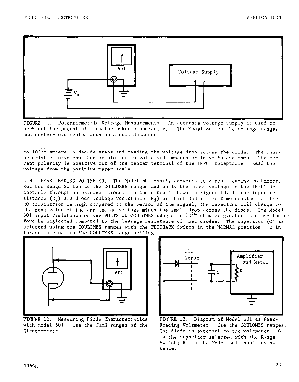
FIGURE 11.
buck out the potential from the unknown source, V,. The Model 601 on the voltage ranges
and center-zero scales acts as a null detector.
to 10-11
acteristic curve can then be plotted in volts and amperes or in volts and ohms.
rent polarity is positive out of the center terminal of the INPUT Receptacle.
voltage from the positive meter scale.
3-8.
Set the Range Switch to the COULOMBS ranges and apply the input voltage to the INPUT Receptacle through an external diode.
sistance (Ri) and diode leakage resistance (Rd) are high and if the time constant of the
RC combination is high compared to the period of the signal, the capacitor will charge to
the peak value of the applied ac voltage minus the small drop across the diode.
601 input resistance on the VOLTS or COULOMBS ranges is 1014 ohms or greater, and may therefore be neglected compared to the leakage resistance of most diodes.
selected "sine the COULOMBS ranges with the FEEDBACK Switch in the NORMAL position.
'PEAK-READING VOLTMETER.
farads is eaual to the COULOMBS-ranee sett
Potentiometric Voltage Measurements. An accurate voltage supply is used to
ampere in decade steps and reading the voltage drop across the diode.
Read the
The Model 601 easily converts to a peak-reading voltmeter,
In the circuit shown in Figure 13, if the input re-
The capacitor (C) is
:in
g
0
0
"I
JlOl
Input
t
I
I
I
I
I
I
Amplifier
and Meter
Ri
The char-
The cur-
The Model
C in
i+ItiUKE IL. measurmg umae knaraccer~scv2s
with Model 601. Use the OHMS ranges of the
Electrometer.
0966R
F
IGURE 13.
Reading Voltmeter.
The diode is external tc the voltmeter. C
is the capacitor selected with the Range
Switch; Ri is the Model 601 input resistance.
Diagram of Model 601 as Peak-
Use the COULOMBS ranges.
23
Page 26

APPLICATIONS
MODEL 601 ELECTROMETER
IGURE 14.
matograph.
Measuring Output of Gas ChroThe Model bOL is usetul as a
_ _-.
_ .
sensitive current detector in a gas chromatograph.
Floating the Electrometer permits grounding the polarizing power source
and flame column.
IGURE 15.
Monitoring Anode of Photomultiplier. The Model 601 permits monitoring
the anode current of a photomultiplier where
both the cathode and power supply must be
grounded.
With its case grounded, all Model
601 front panel controls are also at ground.
24
0666R
Page 27

MODEL 601 ELECTROMETER
CIRCUIT DESCRIPTION
SECTION 4. CIRCUIT DESCRIPTION
4-l. GENERAL.
ter with a full-scale sensitivity of 1 millivolt and an input impedance of 1014 ohms shunted by 2.0 picofarads.
are selected to make measurements over a total of 73 voltage, current, resistance and
charge ranges. Current and resistance are measured using precision resistance standards,
from lo-ohm wirewound resistors to 1011
is measured using close tolerance polystyrene film capacitor standards.
4-2. VOLTMETER OPERATION.
The voltmeter amplifier has matched electrometer input tubes followed by three dif-
a.
ferential transistor stages and a transistor output stage.
feedback is used for stability and accuracy.
for the voltmeter mode of operation.
When there is no input signal and the zero is set,
b.
loop of Figure 16 equals that in the lower loop (ib): i, = ib. With an input signal, the
circuit reacts as follows:
When a positive voltage, +ei, is applied to the input, the amplifier drives the
1.
base of transistor 0202 less negative, and current i,
drop through the Multiplier Switch resistor, R,,,.
therefore, it keeps the voltage drop,
input voltage.
The Keithley Model 601 is basically an extremely stable Linear dc voltme-
By using the front panel controls,
ohm glass-sealed high meoghm resistors. Charge
Figure 16 shows the simplified circuit
At equilibrium this drop equals ei;
e,, across the amplifier to a fraction of the
shunt resistors and capacitors
A large amount of negative
the current (ia) in the upper
is decreased causing a voltage
Amplifier [
>
t
101 ei
1
I
FIGURE lb. Simplified Circuit of Model 601 in Voltmeter Mode.
to schematic diagram. ei is the input voltage;
fier. Rm is the resistor for a given Multiplier Switch setting. ec, is the voltage drop
across R,,,. 5105 is the unity-gain terminal; J106, ohms guard terminal.
stantaneous currents within the loops.
.
t
ea
i
Floating Ground
Output Ground
Circuit designations refer
ea is the voltage drop across the ampli-
ia and ib are in-
Ground references correspond to schematic diagram.
0667R
25
Page 28

CIRCUIT DESCRIPTION
When a negative voltage, -ei, is applied to the input, the amplifier drives the
2.
MODEL 601 ELECTROMETER
base of transistor 0202 more negative, and i, is increased. The current in the lower
loop,
ib, becomes greater than i,, producing a voltage drop, eo, across R,,,. The drop
is sufficient to null the negative input voltage, ei, again keeping the voltage drop
across the amplifier to a fraction of the input voltage.
The voltage drop
3.
imately lo5
The output stage,
C.
on the 0.001 to 0.3-volt ranges.
the,same potential as the input signal.
~CYXISS
the amplifier is e, = ei/(ktl); k is the loop gain, approx-
transistors Q202 and Q203, drives the amplifier common at nearly
Using this circuit,
the input can accept voltages
up to fl0 volts without input dividers. This maintains high input impedance and eliminates
instabilities which can occur with high resistance dividers.
4,-3. VOLTMETER CIRCUIT.
Two balanced electrometer tubes are used for the amplifier input. Their filaments
a.
are operated in parallel from batteries B201 and B202.
the control grid of VlOl,
overloads.
Capacitors Cl01 and Cl11 are high-frequency bypasses. The control grid of
the active electrometer tube, from excessive grid current due to
Resistors RlOl and R114 protect
~102 is returned to amplifier common (floating ground).
NOTE
Refer to Schematic Diagram 194.283 for circuit designations.
b. Depressing the ZERO CHECK Button, S102, connects the junction of resistors RlOl and
Rll4, to circuit low. .This removes all signal from the grid of VlOl, and the input impedance is reduced to 10 megohms.
An emitter follower stage,
c.
transistors 0101 and Q102, matches the relatively high
output impedance of the electrometer tube to the low input impedance of the differential
amplifier stage formed by transistors 9103 and QlO4,.
differential amplifier stage, transistors Q105 and Q106.
This latter stage drives a second
Transistor Q106 drives the com-
plimentary pair output stage, transistors Q202 and Q203.
d. The zero balance controls adjust the dc voltages of the electrometer tube screen
grids. ,The screen grids of VlOl and V102 are returned, in effect, to the emitters of
transistors ~101 and QlO2 through the COARSE and MEDIUM ZERO Switches, S103 and S104.
emitter voltage of QlOl and Q102 can very,
resulting in a negative feedback loop for sig-
The
nals in phase at the electrometer tubes through the QlOl and Ql02 emitter circuit back to
the VlOl and V102 screen grids.
tial and tube operating points.
This connection stabilizes the electrometer plate potenAlso, for signals arriving at the VlOl control grid, the
gain of the first stage will be much greater than spurious signals.
e. The voltage drop across the Multiplier Switch resistors, R162 through R170, deter-
mines the voltmeter sensitivity.
Applying a full-scale signal to the input causes a 1.1
milliampere current to flow through the meter circuit and the selected Multiplier Switch
resistor producing a full-scale meter deflection.
26
0567R
Page 29

MODEL 601 ELECTROMETER
CIRCUIT DESCRIPTION
Input
JlOl
Amplifier
18~ .Z
T
I
1
I
I
Output Gnd
] 1 NORMAL
[GURE 17.
schematic diagram.
resistor selected by the Range Switch, SlOl.
ences correspond to ,schematic.
The recorder output is derived from the current flow from transistor Q203 through
f.
the Multiplier Switch resistor. With the Output Switch, 5108, on lV, *l volt for fullscale deflection is obtained at the output connector, JlO3, by i-l.1 milliamperes flowing
through resistor R173. With SLOB at 1 MA, resistors Rl71 and R172 are connected across
JlO3, allowing fl milliampere to pass through an external load. With an external load of
1400 ohms the current may be varied by *5% by the IMA Cal Control, potentiometer R172.
Block Diagram of Model 601 as a Pi&xxxrmeter.
R,,, is the resistor for a given Multiplier Switch setting.
Floating Gnd
Circuit designations refer to
Rs
is
the
SlO5 is the FEEDBACK Switch. Ground refer-
NOTE
The "normal" and "fast" referred to below are only the positions, of the FEEDBACK
Switch. "Normal method" Fs when the Switch is set to NORMAL: "fast method" is
when the Switch is set to FAST.
4-4,. AMMETER OPERATION.
Normal Method.
a.
NORMAL position),
(See Figure 17.)
meter is calibrated to read the current in amperes for the appropriate range.
b. Fast Method.
position), the Model 601 functions as an annneter with negative feedback.
amplifier output is divided by the Multiplier Switch resistors, Rl62 to R170, and fed back
to the amplifier input through a feedback resistor selected with the Range Switch. (See
Figure 17.) Amplifier low (floating ground) is connected to the low impedance side of the
input,
minimizing the effects of input capacity;
millivolt.
0667R
and the output ground is floating. This method increases the response speed by
1n the normal method of current measurements (FEEDBACK Switch in
one of the Range Switch resistors, R102 through Rll2, shunts the input.
The Model 601 then measures the voltage drop across the resistor.
1n the fast method of current measurements (FEEDBACK Switch in FAST
The differential
it also reduces the input drop to less than 1
The
27
Page 30

CIRCUIT DESCRIPTION
MODEL 601 ELECTROMETER
= E/RE! 1,
18~ I=
4
18~ =
2
+
T
m
lit
FIGURE 18.
designations refer to schematic diagram. Rm is the resistor for a given Multiplier Switch
setting.
graph 4,-5); Rs is the range resistor selected with the Range Switch.
correspond to the schematic.
Block Diagram of Model 601 for Normal Method of Measuring Resistance.
Rx
is the unknown resistance being measured; E is the voltage source (see para-
Ground references
Cira
4-5.
NORMAL position),
Figure,lB.
Rx. The source is obtained from battery B203 through the resistor divider network, R201
through R203.
voltage
stage through Rs, the range resistor. Rs is one of the resistors, R102 through R112.
Since feedback to the amplifier low (floating groun&) keeps the base of transistor Q203
at nearly the same potential as the collector, the current, I, through Q and R, is constant. I is equal to E/R,, regardless of the value of s, as long as the voltage drop
across G does not exceed the Multiplier Switch setting.
source regardless of the input. The Model 601 can then measure the voltage drop across
Rx and indicate the resistance value on its calibrated meter.,
in FAST position and the sample resistance connected between the input terminal, X01, and
the OHMS GUARD terminal, JlO6),
19.
reduces the slowing effect of the instrument's input capacity.
also reduced, since the potential across the input terminal is small.
amplifier low (floating ground) is connected to the low terminal of the INPUT Receptacle
and the output ground is floating.
OHMMETER OPERATION.
Normal Method.
a.
Rx is the unknown resistor. A voltage source, E, applies a potential across
E varies from 0.1 to 8.4 volts, depending upon the OHMS range used. The
source is connected between floating ground and the second differential amplifier
Guarded Method. In the guarded method of resistance measurements (FEEDBACK Switch
b.
The circuit is similar to the normal method, except for the feedback.
In'the normal method of resistance measurements (FEEDBACK Switch in
the Model 601 uses a constant-current, voltage-drop circuit. Refer
This circuit provides a true
feedback is applied through the sample. Refer to Figure
This circuit
Errors due to leakage are
In this mode,
The guard terminal is at output ground potential.
to
Page 31

MODEL 601 ELECTROMETER CIRCUIT DESCRIPTION
I
l-Y--+!9
I i 1 / Am~lif~r / jt ~202
t
Gnd
Floating
18~ Z
T
FIGURE 19. B.lock Diagram of Model 601 for Guarded Method of Measuring Resistance.
designations refer to schematic diagram. Rm is the resistor for a given Multiplier Switch
setting. Rx is the unknown resistor being measured;
4-5); Rs is the range resistor selected with the Range Switch. J106 is the OHMS GUARD
terminal. Ground references correspond to the schematic.
4-6.
that used for an ammeter with the fast method. A negative feedback is applied around a
shunt capacitor, Cl07 to CllO, selected with the Range Switch.
places R, in Figure 17.
citor,
in the Normal or Fast method to measure charge,
COULOMBMETER OPERATION. The Model 601 circuit for measuring charge is similar to
The stored charge is proportional to the voltage across the capa-
which is measured by the Model 601 voltmeter circuits.
the same as to measure current.
E is the voltage source (see paragraph
The shunt capacitor re-
The Model 601 may be used
Cira
,t
0667R
29
Page 32

SERVICING MODEL 601 ELECTROMETER
Instrument
Use
Keithley Instruments Model 153 Microvolt- General circuit checking
Ammeter; 10~~ to lOOOv, 200MR input resis-
tance, *l% accuracy; float *500x7 off ground
Keithley Instruments Model 24,l Regulated
Source to calibrate 1 to LO-volt ranges
High Voltage Supply; 0 to 1000 v, *0.05%
Keithley Instruments 260 Nanovolt Source;
Source to calibrate 1 mv to 1 v ranges
10-3 to 1 ", 10.25%
Keithley Instruments Model 6011 Input
Connecting cable for Models 601 and 260
Cable,; supplied with Model 601
Keithley Instruments Model 6012 Triaxial
to Coaxial UHF Adapter
Adapts the Model 601 for use with in-
struments and accessories with coaxial
connection?..
;I;:;;yyl;"st
ruments Model 261 Picoampere
to 10m4, ampere
Keithley Instruments Model 370 Recorder
Keithley Instruments Model 2611 Test
Source to calibrate current, resistance
and charge ranges
Monitor drift
Connecting cable for Models 601 and 261
Cable; Supplied with Model 261.
Keithley Instruments'Model 515 Megohm
Bridge
Keithley Instruments Model 662 Guarded
Differential Voltmeter; 100 WV to 500 v,
kO.Ol%
TABLE 3. Equipment Recommended for
Model
instruments or their equivalents.
Verify high-megohm resistors in Range
Switch
Calibrate Meter zero
601 Cal .Fbration
and
Troubleshooting.
30
0667~
Page 33

MODEL 601 ELECTROMETER
SERVICING
SECTION 5.
5-1.
Model 601 Electrometer.
performance of the instrument.
5-2.
convenient battery check as described in paragraph 2-4. Except for battery replacement
the Model 601 requires no periodic maintenance beyond the normal care required of high-
quality electronic equipment.
should be checked approximately every six months for specified accuracy.
balance requires occasional adjustment; see paragraph 6-4.
5-3.
Electrometer.
meet the specifications
from Keithley Instruments, Inc. In normal use,
10,000 hours of operation.
could be used in an emergency, but the drift,
not be met.
GENERAL.
SERVICING SCHEDULE.
PARTS REPLACEMENT.
The Replaceable Parts List in Section 8 describes the electrical components of the
a.
The electrometer tubes, VlOl and V102, are specially matched and aged; order only
b.
Section 5 contains the maintenance and troubleshooting procedures for the
Follow these procedures as closely as possible to maintain the
Periodically check the condition of the batteries, using the
The value of the high-megohm resistors, RllO, Rlll, Rll2,
Replace components only as necessary.
They can be checked only by replacement.
SERVICING
The dc amplifier
Use only reliable replacements which
they should not need replacement before
Standard 5886 tubes
noise and grid current specifications may
NOTE
when replacing the electrometer tubes,
leads emerge.
Transistor pairs QlOl, Q102 and Q103, Q104 are matched for dc beta (hFE). Order
c.
only from Keithley Instruments, Inc.,
5-4.
ocz;r in the Model 601. Use the procedures outlinedtand use only specified replacement
parts. Table 3 lists equipment recommended for troubleshooting.
be readily located or repaired,
cated in the table do not clear up the trouble, find the difficulty through a circuit-by-
circuit check,
tion 4 to find the more critical components and to determine their function in the circuit.
The complete circuit schematic, 194283, is in Section 8.
5-5. PROCEDURES TO GUIDE TROUBLESHOOTING.
theOUTPUT Switch. This switch should not be in the IMA Position with no load.
are found satisfactory, use the following procedures to isolate the trouble.
TROUBLESHOOTING.
The procedures which follow give instructions for repairing troubles which might
Table 4 contains the more common troubles which might occur.
b.
If the instrument will not operate, check the condition of the batteries. Then check
a.
Increased leakage will result from any contamination.
or its representative; replace only as a pair.
contact Keithley Instruments, Inc., or its representative.
such as given in paragraph 5-5.
do not touch the glass base where the
If the trouble cannot
If the repairs indi-
Refer to the circuit description in Sec-
If these
0667R
31
Page 34

SERVICING
MODEL 601 ELECTROMETER
Difficulty
Excessive Zero Drift.
Excessive grid current
Excessive microphonics.
cannot meter zero on any
range.
unable to zero meter on
most sensitive range
Meter will not zero on one
Multiplier Switch set- of Multiplier Switch. if faulty.
ting.
Electrometer tubes may be
defective
DC amplifier not balanced.
Batteries failing
Excessive humidity or de-
fective electrometer tube.
Instrument not used.
Defective electrometer tube Check VlOl and VlO2; re-
See paragraph 5-5.
Incorrect plate voltage on Check per paragraph 5-5.
electrometer tube.
Faulty reqistor for setting Check resistors; replace
Probable Cause
Check VlOl and VlO2; re-
place if faulty.
Check per paragraph 6-4,.
Replace batteries (para-
graph Z-4).
Check VlOl and V102; re-
place if faulty.
F&n for seven hours.
place if faulty.
See paragraph 5-5, d.
step 6.
Solution
10-10 to 10-14, ampere Defective high megohm resis- Check per paragraph 6-5.
current ranges are out of tars.
specifications.
TABLE 4,.
b.
voltages referenced to either floating ground or output ground; a properlj, operating
Electrometer will have these 'values *lo% if operating from fresh batteries;
settings for these values are the Range Switch at VOLTS, Multiplier Switch at 1, and the
meter zeroed.
c. At times,
COARSE ZERO Switch, S103 (Figure 3), to bring the Model 601 into balance. If this does
not work, continue to check the circuits.
1. Check the filaments of the electrometer tubes,
voltage drop across the filament dropping resistor, Rl15 (Figure 23).
are operating properly, the voltage will read +1.7 volts dc *lo%.
2.
the amplifier printed circuit board, ~~-115, for possible breaks.
Model 601 Troubleshooting.
The schematic diagram indicates all tube element voltages .and transistor terminal
Measurements are with the Model 153.
the meter will not zero on any range with the input shorted.
Inspect the leads from the shock-mounted input printed circui
See paragraph 5-3 for checking VlOl and V102.
The control
Adjust the
VlOl and V102, by measuring the
If both filaments
board, PC-111, to
32
0567R
Page 35

MODEL 601 ELECTROMETER
Amplifier.
d.
To check the amplifier, disconnect the feedback loop by removing Batteries 8206,
1.
B207, B208 and 0209.
This allows each stage of the amplifier to be individually checked.
SERVICING
It also eliminates the possibility of applying excessive voltage to the electrometer
tube grids,
Connect the Model 153 between the plates of VlOl and V102 (Figure 23). Adjust the
2.
COARSE and MEDIUM ZERO Controls for null.
causing serious damage.
If a null cannot be reached, check VlOl, V102,
the COARSE and MEDIUM ZERO Control circuits (resistors R129 to R150), and transistors
QlOl and Ql02. Check the transistors by removing them and adjusting for null again.
If null is now reached,
replace the transistor pair with a new pair.
3. Check the next stage by connecting the Model 153 across the emitters of QlOl and
Q102 (Figure 25) and adjusting the COARSE and MEDIUM ZERO Controls for null. If null is
not reached,
check this stage and the base circuit of the next stage.
Check the base
circuit by removing transistors Q103 and QlO4 (Figure 25) and again adjusting for null.
If null is now reached,
Check the next stage by connecting the Model 153 across the collectors of QlO3 and
4,.
replace the transistor pair with
Q104, (Figure 25), and adjusting the COARSE and MEDIUM ZERO Controls for null.
a new pair.
If null
is not reached, check this stage and check for shorts in the base circuit of QlO5 and
Q106 (Figure 25).
Connect the Model 153 across the collectors of QlO5 and Q106. Adjust the FINE ZERO
5.
Control for null. If null is reached, the dc amplifier is operating correctly and the
trouble is in the output stage,
The feedback loop includes the multiplier resistors, R162 through R170, the recor-
6.
the feedback stage or in transistor Q201.
der output resistors, R173 on 1V position or R171 and R172 on 1 MA position, and the
meter.
An opening of any of these components prevents zeroing for only that particular
multiplier setting.
Troubleshoot the output stages,
7.
transistors Q202 and Q203, by making voltage measurements with the Model 153 to
within *lo% of the specified schematic
value.
ii&g-1
FIGURE 20. Base Connections for Electrom-
eter Tube VlOl.
0667R
33
Page 36

Page 37

MODEL 601 ELECTROMETER
CALIBRATION
SECTION 6.
6-
1. GENERAL.
The following procedures are recommended for calibrating and adjusting the Model
a.
60
or if difficulty is encountered, contact Keithley Instruments, Inc., or its representa-
tives to arrange for factory calibration.
adjustment, high-megohm resistor verification,
calibration and accuracy check.
6-2.
meter tubes are functioning correctly.
months or when amplifier components are replaced.
six months.
Use the equipment recommended in Table 3.
1.
Procedures are covered for the following:
b.
CALIBRATION SCHEDULE.
Check grid current (paragraph 6-3) at regular intervals to make sure the electro-
a.
The dc amplifier balance adjustment (paragraph 6-4) is necessary about every six
b.
Verify the value of the high-megohm resistors (paragraph 6-5) approximately every
c.
CALIBRATION
If proper facilities are not available
grid current check, dc amplifier balance
calibration of t,he ohms ranges, meter zero
Calibrate the meter zero (paragraph 6-6) about once a year or when components are
d.
replaced.
e. Check the Model 601 (paragraph 6-7) once a year,
improper operation is suspected.
f. If the Model 601 is not within specifications after the calibrations and adjustments,
follow the troubleshooting procedures or contact Keithley Instruments, Inc., or its near-
est representative.
6-3.
petted.
DC Amplifier Balance R204
Meter Center Zero Calibration
Meter Calibration
GRID CURRENT CHECK. Check grid'current whenever excessive noise or drift is sus-
To read the grid current of the Model 601,
METER Switch
Multiplier Switch
Range Switch
ZERO CHECK Button Unlocked
FEEDBACK Switch
Circuit
Control Designation
R211
R220
+
FAST
after the other adjustments, or if
set the front panel controls to:
.Ol
lo-l1 AMPERES
Fig.
Ref. Paragraph
23 6-4
24 6-6
24
Refer to
6-6
TABiE 5. Model 601 internal Controls.
picturing the location and the paragraph describing the adjustment.
0567R
The Table lists all internal controls, the figure
35
Page 38

CALIBRATION
MODEL 601 ELECTROMFIER
Cap the INPUT Receptacle.
2 x
10-14
ampere.
(This is less than 20% of full scale.)
battery condition and the electrometer tube, VlOl.
for a long time,
allow it to run for 7 hours before checking the grid current.
The grid current indicated on the meter should be less than
If this is exceeded, check the
If the instrument has not been used
6-4,. DC AMPLIFIER BALANCE ADJUSTMENT. Gradual aging of components may require an occasional adjustment of the amplifier balance. Also readjust the DC AMP BAL potentiometer,
R204., if amplifier components are replaced.
Set the front panel controls to:
a.
METER Switch
Multiplier Switch
Range Switch
ZERO CHECK Button
FEEDBACK Switch
CENTER ZERO
0.1
VOLTS
LOCK
NORMAL
Zero the meter on the O.l-volt range.
Connect the Model 153 across the collectors of transistors QlO5 and Q106 (this is
b.
across the ends of resistors R152 and R153, Figure 25). Make the connections from the
component side of the printed circuit board.
c. Adjust the DC AMP BAL potentiometer,
Float the Modal 153 low terminal.
R204 (Figure 23), until the meter shows a null.
6-5.
HIGH-MEGOHM RESISTOR VERIFICATION.
a. About every six months, it is necessary to check the value of the high-megohm re-
sistors, RllO to R112, on the Range Switch.
The instrument should be within its rated
accuracy for two or three years from the time it leaves the factory. After this, some
of the resistors may drift out of tolerance and should be replaced. Faulty high-megohm
resistors will affect the‘ accuracies of measurements for the 10Tg to lo-11 AMPERES and the
108 to 1012 OHMS settings of the Range Switch.
To check these resistors,
ac:;racy up to 1011 ohms.
An accurate megohm bridge, such as the Keithley Instruments
it is necessary to use a bridge capable of better than 1%
Model 515 Megohm Bridge which is accurate to 0.25% for these ranges, is therefore neces-
sary.
If such equipment is not available,
two procedures are recommended
to
check out
the resistors:
Return the complete instrument to the factory for resistor calibration.
1.
Replace the high-megohm resistors periodically with a certified set from Keithley
2.
Instruments to assure absolute calibration accuracy.
6-6.
METER ZERO CALIBRATION. Check meter zero whenever components are replaced or other
adjustments are made.
Turn the METER Switch to METER OFF. Set the mechanical Zero Meter adjustment for
a.
'zero meter reading (top-scale zero).
Turn the Model 601 on.
b.
lo-volt range.
INPUT Receptacle.
meter reading.
36
Zero the meter on the .OOl-volt range.
Set the Multiplier Switch to 10;
Adjust the METER CAL potentiometer,
Then switch to the
apply 10 volts t0.05% to the Model 601
R220 (Figure 24), for full scale
0667R
Page 39

MODEL 601 ELECTROMETER
c.
Set the center zero by first zeroing the meter on the .OOl-volt range. Then switch
to the l-volt range.
Set the METER Switch to CENTER ZERO and adjust the CENTER ZERO CAL
potentiometer, ~211 (Figure 24),
CALIBRATION
for exact center-scale meter zero.
6-7.
ACCURACY CHECK.
a. Checking the accuracy is the quickest way to spot faulty Model 601 operation. Per-
form the check about once a year, if components are replaced,
or if other adjustments are
made. If accuracy is verified over all ranges, the Model 601 should be able to meet all
specifications.
b.
Voltage.
lo-volt range.
601 should indicate the input voltage to *l% of full scale.
the 3-volt range.
for accuracy of -f-l% of full scale.
If the accuracy must be checked often, check the stability.
Connect the Model 601 to the Model 241.
Increase the input voltage in l-volt steps from 0 to 10 volts.
First, set the Model 601 for the
The Model
Perform rhe same operation in
Connect the Model 601 to the Model 260. Check the other voltage ranges
Make sure the OUTPUT Switch is in the 1 V position for
the 1, 3 and 10 volt ranges (see paragraph 2-4,g).
c.
Current. Connect the Model 601 to the Model 261 with the Model 2611.
full-scale accuracy of all current positions on the Range Switch.
ampere ranges,
current to *2% of full scale from .3 to 10-S ampere ranges,
to lo-l1 ampere ranges.
output is 10.25%.
d.
Ohms.
more are low, replace them.
not affect the current ranges.
set the FEEDBACK Switch to FAST.
The Model 601 should indicate the input
f&% of full scale from the 10-g
For the ranges above low4 ampere,
construct a current source whose
Set the Model 601 FEEDBACK Switch to NORMAL when calibrating these ranges.
Check batteries B203, ~204 and B205 according to paragraph 2-4.
A low battery can put all the ohms ranges out of tolerance and
Otherwise, all the ohms ranges will be within specifica-
For the 10-5 to lo-11
Check the
If one or
tions if the current ranges are within specifications.
e.
Coulombs.
1.
Calibrate the 10-7 through lo-10
Range Switch
Setting
Time Current
Applied
(seconds)
coulomb ranges using a variable time cur-
rent source.
Set the Model 601 FEEDBACK
Switch to NORMAL and the MULTIPLIER Switch
to 1. Connect the Model 261 to the Model
601 INPUT Receptacle. Set the Model 261
for 10-10
ampere output.
Apply the cur-
rent to the Model 601 for the time noted
in Table 6 for each range.
This procedure
10-7 COULOMBS
10-S COULOMBS
10-g COULOMBS
10-10 COULOMBS
TABLE 6.
Data for Calibrating
100 9315%
100 63*5%
100
5
uses the time constant circuit to check
the range capacitor accuracy.
trometer is being used here as a volt-
The Elec-
Input Current Zero to
meter. Range Switch to Model 601
Setting
(ampere)
2. To check the Model 601 as a charge
amplifier,
and the Multiplier Switch to 3.
set the FEEDBACK Switch to FAST
Use Model
261 to provide an input current. With the
Range Switch set to the COULOMBS ranges
given in Table 7,
input current.
apply the corresponding
Use a stop watch or an
oscilloscope to time the rise to full-
scale deflection.
10-7
COULOMBS
10-S COULOMBS
10-g
COULOMBS
10-10
ABLE 7.
he Table gives the input current needed to
COULOMBS
Coulomb Ranges Accuracy Check.
. I
check the rise time for each coulomb range.
10-S 30
10-g 30
10-10 30
10-11 30
Meter
Reading
63*5%
100*5%
Coulomb
Ranges.
Rise Time,
Full Scale
(seconds)
0667R
37
Page 40

CALIBRATION MODEL 601 ELECTROMETER
6-8.
a.
DRIFT CHECK.
Set the front panel controls to:
Refer to the accuracy check before performing the drift check.
METER Switch
+
Multiplier Switch .03
Range Switch
VOLTS
ZERO CHECK Button LOCK
FEEDBACK Switch NORMAL
Set the Output Switch on the back panel to 1 MA.
b. Connect the Model 601 OUTPUT Receptacle to the Model 370 Recorder.
to 1 volt.
c. Make the drift run for at least 24, hours.
Make sure the Model 601 chassis cover is attached with at least two screws.
The zero drift specification is 200 micro-
Set the recorder
volts per hour maximum averaged over any 24-hour period after warm-up; during two-hour
warm-up, no more than 2 millivolts after the first hour (Refer to Figure 21).
If the instrument does not meet the zero drift specification, check the batteries.
d.
If the batteries are satisfactory and the instrument still does not meet the zero drift
specifications, change the electrometer tubes.
NOTE
If new batteries have been installed, the Model 601 drift specification will be
exceeded for at least the first 72 hours. hit is recommended that new batteries
be used for 120 hours before making a drift run.
FIGURE 21. Typical Drift Chart for Model 601.
The drift run shows the stability of the
Electrometer over a 24.-hour period. After a l-hour warm-up,
millivolts in the second hour.
In any subsequent 24-hour period, the average drift will
not exceed 200 microvolts per hour.
the drift is no more than 2
38
0567~
Page 41

MODEL 601 ELECTROMETER
CALIBRATION
FIGURE 22.
components,
Side View of Model 601 Chassis.
printed circuits and switches is shown.
cuit designations.
Front panel faces right.
Figure 23 shows the opposite side.
CR162
NlXJ)
Location of
Refer to the Parts List for cir-
0866
39
Page 42

CALIBRATION
MODEL 601 ELECTROMETER
FIGURE 23.
Side View of Model 601 Chassis.
components, printed circuits and switches is shown.
designations.
Figure 22 shows the opposite side.
40
Front panel faces left.
Refer to Parts List for circuit
Location of
0866
Page 43

MODEL 601 ELECTROMETER
CALIBRATION
FIGURE 24.
Circuit PC-114.
0866
Component Locations on Printed
FIGURE 25.
Circuit PC-115.
Component Locations on Printed
R‘,C K,?(l
41
Page 44

CALIBRATION
FIGURE 26. Component Locations on Range
Switch SlOl. For other components see
Figures 27 and 28.
FIGURE 27.
Switch 5101.
For other components see
FFgures 26 and 28.
MODEL 601 ELECTROMETER
42
FIGURE 28. Component Locations on Range Switch SlOl.
ponents see Figures 26 and 27.
For other com-
0866
Page 45

MODEL 601 ELECTROMETER
ACCESSORIES
SECTION 7.
7-l. MODEL 6011 INPUT CABLE (Figure 29).
triaxial cable with a mating plug (Keithley Part CS-141), which connect directly to the
Model 601 INPUT Receptacle. Three alligator clips are on separate leads for three-termin-
al connections.
nished with each Model 601.
7-2.
foot triaxial cable. Its insulation resistance is lOlo ohms. The gripping feature is
useful for attaching the probe at a single point for repeated measurements.
terminated by a special triaxial type plug (Keithley Part CS-141).
rectly into the Model 601 INPUT Receptacle. Do not use the Probe for measurements that
are more than 500 volts off ground.
I
MODEL 1531 GRIPPING PROBE (Figure 30). The Model 1531 has a gripping probe and 3-
Refer to Table 1
Page
7 for color coding.
ACCESSORIES
The Model 6011 Cable has 30 inches~of low-noise
One Model 6011 Cable is fur-
The cable is
The plug connects di-
1.
FIGURE 29.
Input Cable.
Keithley Instruments Model 601
IGURE 30. Keithley Instruments Model 153
Gripping Probe.
7-3.
lead. Insulation resistance is more than 1014 ohms. It consists of a probe and 3 feet
of low-noise cable, terminated by a special triaxial type plug (Keithley Part CS-141).
The plug connects directly into the Model 601 INPUT Receptacle.
lows point-by-point guarded measurements.
7-4. MODEL 6012 TRIAXIAL-TO-COAXIAL ADAPTER (Figure 32). The Model 6012 permits using the
Model 601 with all Keithley electrometer accessories having uhf type connectors.
graphs 7-5 through 7-9 describe these accessories. One end of the Adapter is equivalent
to a Keithley CS-141 plug and the other is a uhf-type connector.
FIGURE 31. Keithley Instruments Model 6301
Guarded Probe.
MODEL 6301 GUARDED PROBE (Figure 31). The Model 6301 is a guarded probe and shielded
Using the Model 6301 al-
Para-
--
FIGURE 32. Keithley Instruments Model 6012
Triaxial-to-Coaxial Adapter.
0666
43
Page 46

ACCESSORIES
MODEL 601 ELECTROMETER
NOTE
Do not make off-ground measurements with the Model 601 Electrometer when using
the Model 6012 Adapter.
The Adapter connects case ground and circuit low, de-
feating the Model 601 three-terminal input circuit. The chassis would be at
the same off-ground potential as the voltage being measured.
7-5.
MODEL 6102A VOLTAGE DIVIDER PROBE (Figure 33).
divider with an input resistance of 10" ohms.
100 volts with an accuracy of 3%.
axial cable.
terminated with a uhf plug.
to the Model 601 INPUT Receptacle.
The Probe is furnished with 30 inches of low-noise co-
Use the Model 6012 Adapter to connect the Probe
Instructions for using the Probe with the Electrome-
. . “.-^ I.. ..^r”“r.,..l, 7-5
FIGURE 33.
6102A 1O:l Voltage Divider Probe.
7-6.
MODEL 6103A VOLTAGE DIVIDER PROBE (Figure 34).
divider with an input resistance of 1012 ohms.
10 kilovolts with an accuracy of 5%.
coaxial cable,
Probe to the Model 601 INPUT Receptacle.
trometer are in paragraph 2-5.
Keithley Instruments Model
terminated with a uhf plug.
The Probe is,furnished with 30 inches of low-noise
Use the Model 6012 Adapter to connect the
Instructions for using the Probe with the Elec-
The Model 6102A is a 1O:l voltage
It can be used with the Model 601 up to
FIGURE 34.
Keithley Instruments Model
6103A 1OOO:l Voltage Divider Probe.
The Model 6103A is a 1OOO:l voltage
It can be used with the Model 601 up to
7-7.
MODEL 6104 TEST SHIELD.
a. The Model 6104 facilitates resistance
measurements with either 2-terminal or 3-
terminal guarded connections, as well as
voltage and current tests.
2-Terminal Operation.
b.
Connect the high impedance side of
1.
the test sample to the Model 6104 INPUT
Terminal.
Connect the low impedance side
to either black jack marked GROUND, whichever is more convenient.
Lock the enclosure and connect the
2.
Model 6104 bnc receptacle to the Model
601 INPUT Receptacle, using the Model
6012 Adapter.
Use a short coaxial cable.
Operate the Model 601 as described in
Section 2.
44
.
: ____________ ------_---- ---------,
I
t:
T
I
I
I
mi
1
----------------- YL-- ------------ 1
FIGURE 35.
Diagram of Model 6104 Circuit.
0
0
I
,
I
I
1
I
0666
Page 47

MODEL 601 ELECTROMETER
C. 3-Terminal Operation.
ACCESSORIES
1. For guarded measurements,
make the connections as above with some additional steps.
2. Connect the Model 6104 black external plug to the Model 601 OHMS GUARD Terminal.
Connect either Terminal marked EXTERNAL SOURCE to the test sample at its high im-
3.
pedance side.
Connect an external voltage supply to the banana plugs on the side of the Model
4.
6104, positive to red and negative to black.
thlev Model 240A High Voltage Supply) to the desired voltage.
Lock the enclosure and connect the Model 6104 to the Electrometer.
Set the external source (such as the Kei-
Operate the Electrometer
as explained in Seciion 2
FIGURE 36.
Test Shield.
7-S.
MODEL 6105 RESISTIVITY ADAPTER.
The Model 6105 is a guarded test fixture for measuring resistivities of materials
a.
in conjunction with the Model 601 and the Model 240A High Voltage Supply.
system direct1
ities up to 10
ting and Materials.
tact with uniform pressure.
inch thick.
Keithley Instruments Model 61
FIGURE 37. Keithley Instruments Model 611
Resistivity Adapter.
The complete
measures volume resistivities up to 3 x 10lg ohm-cm and surface resistiv-
KS
ohms,
in accordance with the procedures of the American Society for Tes-
The shielded Model 6105 is a means for maintaining good sample con-
The Adapter holds samples up to 4 inches in diameter and .25
Maximum excitation voltage is 1000 volts.
b. The Model 6105 Instruction Manual explains the operating procedures for the system,
using the Model 240A and an Electrometer.
The Model 601 can also be used with the Model 6105 alone.
a :&stant current source (paragraph 3-2)
with the FEEDBACK Switch in FAST position.
Operate the Model 601 as
Con-
nect the OHMS GUARD Terminal on the rear panel to the center terminal of the Model 6105
0666
45
Page 48

ACCESSORIES
MODEL 601 ELECTROMETER
FIGURE 38.
Static Detector Probe.
Power Receptacle.
rent from the Model 601 is the reciprocal of the OHMS setting of the Range Switch; the
voltage is the Multiplier Switch setting times the meter reading.
7-9.
from the charged surface. Measurements are accurate within 10%.
of a 3-inch diameter head and 10 feet of cable. Connect the Probe to the Model 601 INPUT
Receptacle using the Model 6012 Adapter.
eter and it connects directly into the Electronieter
without any cable.
7-10.
the instrument to rack mounting to the stand&d EIA 19-inch width.
instrument case.
The feet and tilt bail can be removed without removing the bottom cover assembly.
the rear feet first.
front feet and tilt bail and replace the shield.
MODELS 2501 AND 2503 STATIC DETECTOR PROBES.
a. The Model 2501 is a 10,OOO:l capacitive divider when used with the head 3/8 inch
b. The Model 2503 i+ similar to the Model 2501. However, its head is l/2 inch in diam-
RACK MOUNTING (See Figure 40).
a. The Model 601 is shipped for bench use.
b. To convert the instrument, remoye the two,screws at the bottom of each side of the
Keithley Instruments Model 2501
Other operating procedures are as for the 3-instrument system. The cx-
Lift off the top cover assembly with the handles; save the four screws.
Then, remove the shield in the front of the instrument, remove the
FIGURE 39. Keithley Instruments Model 250
Static Detector Probe.
The Model 2501 consists
- with the Model 6012 Adapter L
The Model 4005 Rack Mounting Kit converts
Remove
I
Item
(See Fig. 40) Description
I
3
1
I
46
2 -- Mounting Filler Cover Screw, Assembly No. Panel Panel 10 -
TABLE 8. Parts List for Keithley Model 4005 Rack Mounting Kit.
Keithlev
Part No.
3/8, HSS 19396B 19397B 20018B ---
Quantity
12 1 1 1
0667R
Page 49

MODEL 601 ELECTROMETER
3
0
0
0
0
ACCESSORIES
3
FIGURE 40 .
list.
c. Insert the top cover assembly (1)
screws previously removed. Attach the mounting panel (2) to the rack with four #lo screws
and kep nuts. Fasten the Model 601 to the mounting panel with four #lO screws. Fasten
the filler panel (3) to the opening in the mounting panel with four i/l0 screws and kep
nuts.
If two Model 601 Electrometers are to be rack mounted side-by-side, another top
d.
cover assembly (Keithley Part 19525B) is used instead of item 1 in Figure 40.
panel (3) is not used.
mensions are 10-l/2 inciles high x 6-5/8 inches wide ‘& 10 inches deep.
7-11. MODEL 6013 pH ELECTRODE ADAPTER.
a. The Model 6013 is designed to allow accurate and convenient pH potential measure-
ments with the Model 601 Electrometer. It accepts Leeds & Northrop(L&N), Coleman and
Beckman (B-C) pH electrode connectors.
guarded to insure that the accuracy of the Model 601 is affected in no way.
Exploded View of Model 4005 Rack Mounting Kit.
in place and fasten to the chassis with the four
This Kit will also hold any two Keithley models whose bench di-
The Adapter uses Teflon insulation and’is fully
Refer to Table 7 for parts
The filler
b. The top of the Model 6013 contains two sets of connectors, one of which accepts an
old type L6d\I electrode, while the other accepts either a new type La or the B-C electrode.
Connect the electrodes to the proper set.
Model 601 INPUT Receptacle.
Set the Adapter’s switch for 601.
C.
Set the Range Switch to VOLTS. Use the appropriate range for the Multiplier Switch.
0667R
Connect the Adapter cable directly into the
Set the Model 601 WTER Switch to CENTER ZERO,
47
Page 50

MODEL 601 ELECTROMETER
NOTE
To check zero on the Electrometer, use only the ZERO CHECK Button on the Model
6013 pH Electrode Adapter.
d. For guarded measurements, connect the GUARD Terminal on the Adapter to the Model
601 OHMS GUARD Terminal.
r--------L- "",
I
.
I
4
I
I
Shield
4
>
>
Do not use the ZERO CHECK Button on the Electrometer.
-
Model 6013
I
Zero Check
Guard
---- ---e--B
f
+
I
<
<
(
Ref.
FIGURE 41.
7-12. MODEL 370 RECORDER.
a. The Model 370 Recorder is uniquely compatible with the Model 601 as well as other
Keithley electrometers, microvoltmeters and picoammeters.
economical instrument that maximizes the performance of the Model 601, and many other
Keithley instruments, even in,the most critical applications. The Model 370 can be used
with the Model 601 to record voltage, resistance,
entire range.
b.
The Model 601 has the output necessary to drive the Recorder directly (1 volt, 1
milliampere),
volts off ground.
The response time of the Model 370 Recorder is 0.5 second; linearity is *l% of full scale.
Ten chart speeds -
front panel, controls.
corder has a self-priming inking system.
>
Block Diagram of Model 6013 in use with the Model 601.
The Recorder is's high quality
currents and charge over the Model 601's
thus eliminating the need for a pre-amplifier.
The Recorder is specially shielded to avoid pickup of extraneous signals.
from 3/4, inch per hour to 12 inches per minute - are selectable with
The 6-inch chart has a rectilinear presentation. The Model 370 Re-
Chart paper and ink refills are easy to install.
The Model 370 floats *500
<
C.
The Model 370 is very easy to use with the Model 601.
necting the two units,
accessible control for full-scale recorder deflection.
Cable mates with the output connector on the Model 601.
setting the Mpdel 601 Output Switch to 1MA and adjusting an easily
All that is necessary is con-
The furnished Model 3701 Input
Page 51

MODEL 601 ELECTROMETER
ACCESSORIES
:GURE 4,2. Maximum Recording Convenience is Obtained Using the Keithley Model 370,
specially Designed for use with Keithley Electrometers and Other Instruments.
The Model
'0 can be directly connected to the Model 601 output with the Recorder's accessory cable.
Response time, floating capability and other specifications of the Model 370 Recorder are
compatible with those of the Model 601 Electrometer.
0567
49
Page 52

Page 53

MODEL 601 ELECTROMETER REPLACEABLE PARTS
SECTION 8. REPLACEABLE PARTS
8-1.
REPLACEABLE PARTS LIST.
the Model 601.
manufacturer,
The List gives the circuit designation, the part description, a suggested
the manufacturer's part number and the Keithley Part Number.
The Replaceable Parts List describes the components of
The last column
indicates the figure picturing the part. The name and address of the manufacturers listed
in the "Mfg.
a-2.
HOW TO ORDER PARTS,
For parts orders,
a.
Part Number,
Code" column are in Table 10.
include the instrument's model and serial number, the Keithley
the circuit designation and a description of the part.
All structual parts
and those parts coded for Keithley manufacture (80164) must be ordered through Keithley
Instruments, Inc. or its representatives.
Parts List,
order parts through your nearest Keithley representative or the Sales Service Depart-
b.
completely describe the part, its function and its location.
In ordering a part not listed in the Replaceable
ment, Keithley Instruments, Inc.
amp
CerD
Comp
DCb
EdllpWX
Ceramic, disc
Composition
Deposited Carbon
NO.
n
P
Poly Polystyrene
Number
ohm
pica (LO-l*)
ETB
f
Fig.
GCb
I<
M or meg
Mfg.
MtF
MY
Electrolytic, tubular
Ref. Reference
req'd
farad
Figure
P
Glass enclosed carbon v
kilo (103) w
ww
mega (106) or megohms
wwvar<
Manufacturer
Metal Film
Mylar
TABLE 9.
Abbreviations and Symbols.
required
micro (10-6)
volt
watt
Wirewound
Wirewound Variable
0567R
51
Page 54

REPLACEABLE PARTS
(Refer to Schematic Diagram 194283 for circuit designations.)
MODEL 601 ELECTROMETER
MODEL 601 REPLACEABLE PARTS LIST
BATTERIES
Circuit
Desia.
B201
B202
B203
B204
B205
B206
B207
B208
B209
Description
1.35v mercury
1.35~ mercury
8.4~ mercury
8.4~ mercury
8.4~ mercury
9v zinc carbon
9v zinc carbon
9v zinc carbon
9v zinc carbon
Circuit
Desig.
Value Rating
Cl01 22 pf 600 v
Cl02 125 iJ.f
Cl03
.OOl pf 500 "
Cl04 150 pf
Cl05 150 pf
15 "
500 "
500 "
Mfg.
Code Part No. Part No.
72665 RM42R
72665 PxM42R
72665 TR-286
72665 TR-286
72665 TR-286
09823 2N6
09823 2N6
09823 2N6
09823 2N6
CAPACITORS
Mfg. Mfg.
Type
Code
CerD 72982
ETB 73445
Poly 71590
POlY. 71590
Poly 71590
Mfg.
Keithley
BA-10
BA-10
BA-18
BA-18
BA-18
BA-17
BA-17
BA-17
BA-17
Keithley
Part No.
ED-22
Part No.
c22-22P
C462 C3-125M
CPR-1000J
CPR-150J
CPR-150.J
Cl38-.OOlM
C138-15OP
C138-15OP
Fig.
Ref.
22, 23
22, 23
22, 23
22, 23
22, 23
22, 23
22, 23
22, 23
22, 23
Fig.
Ref.
28
22
28
28
28
Cl06 5 Pf
Cl07 0.1 I.rf
Cl08 .Ol IJ.f
Cl09
.OOl pf
Cl10 100 pf
Cl11 22 pf
Cl12 0.1 pf
Cl13 680 pf
Cl14 0.1 IJ.f
Cl15 .02 IJ.f
cl16
.0011J.f
200 v
200 v
200 "
200 v
500 "
600 v
50 v
600 v
50 v
600 v
600 v
Circuit
Desig. Description
----
----
----
----
Battery holder, 2 req'd
Battery holder, 3 req'd
Battery holder, 4 req'd
Battery retain clips, 6
Poly 14167
Poly a4171
Poly 84171
Poly 84171
Poly 71590
CerD 72982
MY 84411
CerD 72982
MY 84411
CerD 72982
CerD 72982
MISCELLANEOUS PARTS
Mfg.
Code
80164
80164
80164
req'd 80164
E1013-1
c31-5P
2PJ-104G C108-.lM
2PJ-103G ClOB-.OlM
2PJ-102G Cl08-.OOlM
2PJ-1OlG ClO8-1OOP
ED-27
c22-22P
601 PE C41-.lM
ED-680
C22-680P
601 PE C41-.1M
ED-.02
C22-.02M
ED-.001 C22-.OOlM
KeithZey
BH-20
BH-21
BH-6
BH-22
26
27
27
27
27
23
25
25
22
24
22
Fig.
--_--
---
---
52
0667~
Page 55

MODEL 601 ELECTROMETER
REPLACEABLE PARTS
MISCELLANEOUS PARTS (Con't)
Circuit
Desig.
Description
D201 Silicon diode (Number 1~645)
D202 Silicon diode (Number 1~645)
D203 Silicon diode (Number lN645)
3101
-___
JlO2
Receptacle, triaxial, INPUT (Mfg. No. 33050-l)
Plug, triaxial, mate of JlOl (Mfg. No. 30197-l)
Binding Post, LO (Mfg. No. DF21B) 58474
5103 Receptacle, Microphone, OUTPUT (Mfg. No. 80-PC2F)
-___
JlO4
5105
5106
5107
Ml01
(F) Plug, Microphone, mate of 5103 (Mfg. No. 80-MC2M) 02660
Binding Post, CASE GROUND(Mfg. No. DFZLGRN)
Binding Post, XL OUTPUT (Mfg. No. DF2LR)
Binding Post, GUARD (Mfg. No. DF2LBLU) 58474
Binding Post, LO (Mfg. No. DF21B)
Meter 80164 ME-53A
SlOl Rotary Switch Less components, Range
--_-
-___
Rotary Switch with components, Range 80164 19257B
Dial Assembly, Range
Mfg. Keithley
Code
Part No.
Fig.
Ref.
01295 w-14 24
01295 RF-14 24
01295 RF-14
95712
95712
cs-181
cs-141
BPLL-B
02660 CS-32
cs-33
58474
58474
BPlL-GRN
BPll-R
BPLl-BLU
50474
BPLL-B
24
22, 2
___
22, 2
23, 3
---
22, 3
22, 3
22, 3
22, 3
22
80164 SW-204 22, 2
_-_
80164 L7033A
__-
s102
--_-
Push Button, ZERO CHECK
Knob Assembly, Zero Check
s103 Rotary Switch less components, COARSE ZERO
----
Rotary Switch with components, Coarse Zero
s104 Rotary Switch less components, MEDIUM ZERO
----
s105
Slob
--_-
----
5107
____
sloa
-_-_
Rotary Switch with components, Medium Zero 80164 1926LB
Slide Switch, FEEDBACK
Rotary Switch less components, Multiplier
Rotary Switch with components, Multiplier
Dial Assembly, Multiplier 80164 19223A
Rotary Switch, METER
Knob Assembly, Meter 80164 14825A
Slide Switch, OUTPUT 80164 SW-45 23, 3
Knob Assembly, Fine Zero Control
(F) Furnished Accessory
80164
80164
80164
80164
L4376A 23, 2
18038A
SW-166
19283B
_-_
22, 3
___
80164 SW-209 22, 2
__-
80164
19089A
80164 SW-205
80164
L9263B
23, 2
22, 2
---
---
80164
SW-206 23, 2
---
80164 L6995A
---
0667R
53
Page 56

REPLACEABLE PARTS
MODEL 601 ELECTROMETER
RESISTORS
Circuit
Desig.
RlOl
R102
R103
Rl04
R105
Rl06
Rl07
Rl08
R109
RllO
Rlll
R112
R113
R114
R115
R116
Rl17
Value
10 m
10 n
100 n
1 kn
10 kn
100 ksl
1m-l
10 m
100 l"n
109 n
1010 n
1011 n
800 kn l%, l/2 w
10 m
10 kn
2.2
kn
150 kn
Rating
lO%, l/2 w
TYPE
Comp 01121
l%, 10 w Liw
l%, 10 w biw
l%, 1/2 w
l%, l/2 w
l%, l/2 w
l%, l/2 w
lO%, 1 w DCb 91637 DC-1
e
l/,, 2 w
DCb
DCb 79727 CFE-15 R12-10K
DCb 79727 CFE-15
DCb
DCb 91637 D-2
t3-O%, l/R w GCb
t3-0%, l/R w GCb 63060
t3-0%, l/R w GCb
DCb 79727 CFE-15 R12-800K
lO%, l/2 w Comp
l%, l/2 w
DCb
lO%, l/2 w Comp 01121
l%, l/2 w
DCb 79727 CFE-15
R118 150 kn l%, II2 w MtF
R119
Rl20
10 kn
1.2 kQ
5%, 2 w
l%, l/2 w
wwvar
W
Mfg.
Mfg.
Keithley
Code Part No. Part No.
EB Rl-1OM 28
91637
91637
RS-10 R34-10 27, 28
RS-10 R34-100 27, 28
79727 CFE-15 R12-1K
R12-100K
79727
CFE-15
R12-1M
R13-10M 28
R14-100M
63060
63060
01121
Rx-1
Rx-1
R20-109
R20-1010
RX-1 R20-1011
EB
Rl-1OM
79727 CFE-15 R12-10K
EB Rl-2.2K
R12-150K
07716
12697
79727
CEC
62~~ RP42-10K
CFE-15
R94-150K
R12-1.2K
Fig.
Ref.
28
28
28
28
26, 28
26
26
26
27
23
23
25
25
25
22, 2
22
R121
R122
Rl23
Rl24
150 kn l%, l/2 w MtF
15 kn
68
m
450 kn
R125 450 IQ
R126
Rl27
R128
R129
Rl30
R131
R132
Rl33
R134
Rl35
R136
R137
R138
R139
R140
100 kn
15 ksl
68 kn
15 kIl
2
ksl
2
kn
2
kn
2kQ
2kcl
2
kn
2
kn
2
kn
2
kn
2
kn
402 n
l%, l/2 w
DCb 79727 CFE-15 R12-15K
l%, l/2 w DCb
l%, l/2 w
l%, l/2 w
lO%, l/2 w
1%, l/2 w
l%, l/2 w
l%, l/2 w
l%, l/2 w
l%, l/2 w
l%, l/2 w
l%, l/2 w
l%, l/2 w
l%, 112 w
l%, k/2 w
l%, l/2 w
l%, l/2 w
l%, l/2 w
l%, 112 w
DCb 79727 CFE-15 R12-450K
DCb 79727 CFE-15 R12-450K
Comp
DCb
DCb
DCb
DCb
DCb
DCb
DCb
DCb
DCb
DCb
DCb
DCb
DCb
DCb
07716
CEC R94-150K
79727 CFE-15
01121
79727
79727
79727
79727
79727
79727
79727
79727
79727
79727
79727
79727
79727
79727
EB Rl-100K
CFE-15 R12-15K
CFE-15
CFE-15 R12-15K 22
CFE-15 R12-2K 22
CFE-15 Rl2-2K 22
CFE-15
CFE-15 R12-2K
CFE-15 R12-2K 22
CFE-15 R12-2K 22
CFE-15 R12-2K
CFE-15 R12-2K
CFE-15
CFE-15 R12-2K
CFE-15 R12-402
R12-68K
R12-68K
R12-2K
R12-2K
25
25
25
25
25
25
25
25
22
22
22
22
22
22
22
54,
0667R
Page 57

MODEL 601 ELECTROMETER
REPLACEABLE PARTS
RESISTORS (Con't)
circuit Mfg. Mfg.
Desig.
R141
Rl42
Rl43
R144
R145
R146
R147
R148
R149
R150
R151
R152
R153
R154
R155
R156
Rl57
R158
R159
Rl60
Value Rating
402 n
402 n
402 n
402 n
402 n
402 n
402 R
402 n
402 R
15 m
10 kn
80 kn
80
kn
1.5 kil
3.3 kn
3.3 kn
22 kQ
22
kn
30
kn
15 kn
l%, l/2 w
l%,
II2 w
l%,
l/2 w
l%,
l/2 w
l%, 112 w
l%,
l/2 w
l%,
II2 w
l%,
l/2 w
l%,
l/2 w
l%, l/2 w
lO%,
l%,
l/2 w
l%, l/2 w
lO%, l/2 w
lO%,
lO%,
l%,
l/2 w
l%,
l/2 w
l%,
l/2 w
l%,
l/2 w
l/2 "
l/2 w
l/2 w
TYPO
DCb
DCb 79727 CFE-15 R12-402
DCb
DCb 79727
DCb 79727 CFE-15
DCL! 79727 CFE-15 R12-402
DCb 79727 CFE-15 R12-402
DCb 79727 CFE-15 R12-402
DCb 79727 CFE-15 RlZ-402
DCb 79727
camp 01121 EB
DCb
DCb 79727
camp 01121
Comp 01121
Comp 01121
DCb 79727 CFE-15 Rl2-22K
DCb 79727
DCb
DCb
Code Part No. Part No. Ref.
79727
79727
CFE-15
CFE-15
CFE-15
CFE-15
79727
CFE-15 R12-80K
CFE-15
EB Rl-1.5K
EB Rl-3.3K
EB
CFE-15
79727 CFE-15
79727
CFE-15 Rl2-15K
Keithley
Rl2-402
R12-402
Rl2-402
R12-402
Rl2-15K
Rl- 10K
RlZ-80K
Rl-3.3K
Rl2-22K
Rl2-30K
Fig.
22
22
22
22
22
22
22
22
22
22
25
25
25
-__
25
__
__
__
__
R161
Rl62
R163
R164
R165
R166
R167
R168
R169
R170
R171
R172
R173
R174
Rl75
R176
R201
R202
R203
~204
R205
2.2
kfi
9.1 kc
2.73
kn
910 n
273 n
91 n
27.3 n
9.1 n
2.73 n
.Vl n
8.6
kn
20
kn
910 n
10 n
470 n
10 R
1 k0
9 kR
70
k0
10 kfl
180 kQ
l%,
l/2 w
0.5%, l/2 w
0.5%, II2 w
0.5%, II2 w
0.5%, l/2 w
0.5%, II2 w
0.5%, l/2 w
0.5%, l/4 w
0.5%, l/4 w
0.5%, l/4 w
l%,
l/2 w
lO%, 5 w
0.577, 112 w
lO%,
lO%,
II4 w
l/2 w
lO%, l/4 ”
l%,
II2 w
l%, l/2 w
I%, 112 w
lO%, 5 w
lO%, 112 w
DCb 79727
MtF 07716
MtF
MtF
07716 CBC R61-2.73K
07716
MtF 07716
MtF
MtF
07716
07716 CBC R61-27.3
ww 01686
ww 31686
ww
01686 T-2A R123-.91
DCb 79727
War 71450
MtF
camp
Comp
07716
01121
01121
Comp 01121
DCb 79727
DCb 79727
DCb 79727
WWvar 71450
camp
01121
CFE-15
Rl2-2.2K
CBC R61-9.1K
-_
22
22
CBC
CBC R61-273
CBC
R61-910
R61-91
22
22
22
22
T-2A R123-9.1
T-2A R123-2.73
22
22
22
CFE-15 R12-8.6K
AW RP34-20K
23
23, 3
CEC R61-910 23
CB
R76-10
EB Rl-470
CB
CFE-15
R76-10
RlZ-1K
CFE-15 RLZ-9K
CFE-15 RlZ-70K
-_
22
_-
24
24
24
AW RP3-1OK 23
EB
Rl-180K
24
0667~
55
Page 58

REPLACEABLE PARTS
MODEL 601 ELECTROMETER
RESISTORS (Con't)
Circuit Mfg.
Desig.
R206
R207
R208
R209
R210
R211
R212
R213
R214
R215
R216
R217
R218
R219
R220
Value
820 n
820 n
39 kn
180 kn
1 kn
1 kn
180 kn
330 n
15 kn
120 kn
330 n
15 kn
120 kn
500 n
2
kn
Rating
lO%,
l/2 w
lO%, l/2 w
lO%, l/2 w
lO%,
l%,
l/2 w
l/2 w
lO%, 5 w
LO%, l/2 w
lO%,
lO%, l/2 w
lO%,
lO%,
lO%,
lO%,
l%,
l/2 w
l/2 w
l/2 w
l/2 w
l/2 w
l/2 w
lO%, 5 w
TYPO
Comp
Comp
Comp
Comp
DCb
WWVar
Camp
Comp
Comp
Camp
Comp
Comp
camp
DCb
WWVar
Code
01121 EB
01121 EB
01121 EB
01121 EB
79727 CFE-15
71450 AW
01121 EB
01121 EB
01121 EB
01121 EB
01121 EB
01121 EB
01121 EB
79727 CFE-15
71450 AW
TRANSISTORS
Circuit
Desig.
Number
Mfg.
Code
Mfg.
Keithley
Part No. Part No.
Rl-820 24
Rl-820 24
Rl-39K 24
Rl-180K 24
R12-1K 24
RP34.-1K 24
Rl-180K 24
Rl-330 24
Rl-15K 24
Rl-120K 24
Rl-330 24
Rl-15K 24
Rl-120K 24
R12-500 24
RP34-2K 24
Keithley
Part No.
Fig.
Ref.
Fig.
Ref.
QlOl
4102
Q103
4104
QlO5
Q106
Q201
Q202
Q203
4204
4205
4206
Circuit
DesFg .
VlOl
v102
A1380
A1380
A1380
A1380
S17638
S17638
Al380
2N1605
2N1381
S17638
S17638
517638
Number
5886
5886
80164 TG-32
80164 TG-32
80164 TG-32
80164 TG-32
07263 TG-33
07263 TG-33
73445 TG-32
93332 TG-22
01295 TG-8
07263 TG-33
07263 TG-33
07263 TG-33
VACUUM TUBES
Mfg.
Code
Keithley
Part No.
80164 ""EV-5886-3P
80164 **EV-5886-3P
25
25
25
25
25
25
24
24
24
24
24
24
Fig.
Ref.
23
23
** Replace VlOl and V102 as a pair.
56
06678
Page 59

MODEL 601 ELECTROMETER
REPLACEABLE PARTS
01121 Allen-Bradley Corp.
Milwaukee, Wis.
01295 Texas Instruments Inc.
Semi Conductor-Components Division
Dallas, Texas
01686 RCL Electronics, Inc.
Riverside, N. J.
02660 Amphenol-Borg Electronics Corp.
Broadview, Chicago, Illinois
07263 Fairchild Camera & Instrument Corp.
Semiconductor Division
Mountain View, Cal.
07716 International Resistance Co.
Burlington, Iowa
09823 Burgess Battery Co.
Freeport, Ill.
12697 Clarostat Mfg. Co., Inc.
Dover, N. H.
71450 CTS Corp.
Elkhart, Ind.
71590 Centralab Division of
Globe-Union, Inc.
Milwaukee, Wis.
72665 Mallory Battery Co.
Cleveland, Ohio
72982 Erie Technological Products, Inc.
Erie, Pa.
73445 Amperex Electronic Co. Division o
North.American Philips Co., Inc.
Hicksville, N. Y.
79727 Continental-Wirt Electronics Corp
Philadelphia, Pa.
80164 Keithley Instruments, Inc.
Cleveland, Ohio
84171 Arco Electronics, Inc.
Great Neck, N. Y.
14167 Efcon, Inc.
Garden City, Long Island, N. Y. Ogallala, Nebr.
56289 Sprague Electric Co.
North Adams, Mass.
58474 Superior Electric Co., The
Bristol, Corm. Semiconductor Products Division
63060 Victoreen Instrument Co.
Cleveland, Ohio 95712 Dage Electric Co., Inc.
TABLE 10. Code List of Suggested Manufacturers.
facturers, Cataloging Handbook H4-1.)
84411 Good-All Electric Mfg. Co.
91637 gale Electronics, Inc.
Columbus, Nebr.
93332 Sylvania Electric Products, Inc.
Woburn, Mass.
Franklin, Ind.
(Based on Federal Supply Code for Manu-
0667R
57
Page 60

CHANGE.NOTICE
January. 9, 1967
Page 53.
Change to the following:
Circuit
Desig.
.
Ml01
Description
Meter
MODEL 601 ELECTROMETER
Mfg.
Code
Keithley
Part No.
'%0164 ME-81
Fig.
Ref.
22
Page 61

CHANGE NOTICE
August 29, 1967
Page 3.
ISOLATION:
microfarad.
Page 54.
Change the ISOLATION Specification to the following:
Circuit ground to chassis ground:
gr?ater than
9 ohms shunted by 0.0015
10
Circuit ground may be floated up to -1500 volts with respect to chassis ground.
Change to the following: ’
circuit Mfg. Mfg.
Desig.
Value Rating
R108 10 MQ
TYPO
l%, l/2 w DCb
Code
Part No. Part No. Ref.
79727 CFE-15 Rl2-1OM 28
MODEL 601 ELECTROMETER
Keithley
Fig.
Page 62

CHANGE NOTICE
MODEL
‘$13
pH ELECTRODE ADAPTER
Pane 1. The second sentence in the first paragra~ph should be changed to:
One hole accepts either a Beckman and Coleman (B-C) or a new type~Lee,ds and
Northrup connector. The other hoie accepts an old type Leeds and Northrup connector.
Page 63

.
MODEL 6013
pH ELECTRODE ADAPTER
1. GENERAL.
a. The Keithley Model 6013 pH Electrode Adapter is designed to allow accurate and con-
venient pH potential measurements w,ith both the Keithley Model 601 Electrometer and the
Keithley Model 630 PotentiometricElectrometer.
It accepts a Beckman and Coleman (B-C)
or a Leeds and Northrup (L&N) connector. The two terminals marked REF accept a banana
jack or a phone tip jack.
The Adapter uses Teflon insulat$on.on a1.J high impedance connections and is fully -~-
b.
guarded to insure that the accuracy~of ~the Model 60l.qr the Model 6.3~0 is affected in no ~_
way.
out shorting the pH electrodes.
The ZERO CHECK Button on the Model 6013 ,alLows checking zero on the Model 601 with-
The Adapter can float off ground with either the Model
' 601 or the Model 630.
2. USE WITH THE MODEL 601 ELECTROMETER.
a. To use the Model 6013 with the Model 601, set the Transfer Switch on the Model 6013
to the 601 position. Set both the ZERO CHECK Button on the Model 601 and the ZERO CHECK
Button on the Model 6013 to the LOCK Position. Place the FEEDBACK Switch on the Model 601
in
the FAST PosFtFon.
b. Connect the Adapter cable directly into the Model 601 INPUT Receptacle.
Connect the
TO GUARD Terminal on the Model 6013 to the OHMS GUARD Terminal on the rear panel of the
Model 601.
c. Open the ZERO CHECK Button on the Model 601.
Insert the pH electrodes into the
Model 6013.
d. To obtain a reading,
set the Model 601 METER Switch to CENTER ZERO.
Switch to VOLTS. Use the appropriate range for the Multiplier Switch.
CHECK Button on the Model 6013.
Read the voltage off the lower meter scale. To convert
Set the Range
Open the ZERO
the voltage to pH, refer to Figure 2.
NOTE
To check zero on the Model 601, use only the ZERO CHECK Button on the Model 6013.
Do not use the ZERO CHECK Button on the Model 601. The Button on the Model 6013,
is zign&d to disconnect the Hi electrode before shorting the Model 601 leads.
If the Model 601 ZERO CHECK Button is used to check zero, the electrodes will
be shorted and may be damaged.
e. The Adapter will float off ground with the Model 601.
3.
USE WITH THE MODEL 630 POTENTIOMETRIC ELECTROMETER.
. '_
.a. To use the Model 6013 with theMode 630, set the Transfer Switch.on the Model 6013
to the 630 position.
b. conrie.2t the .\&pter Cl512 d<rx.cly iFto the !~Lxl?L 630 INPU-I Kec~plx;,.
Connect the
TO <Xi) Tlr;iiixiL on the >Iodel 6013 to the CND Terminal on the front panel of the Model 630.
0966
L
Page 64

To obtain a reading set the Model 630 NULL Switch to the VTVM Position., Switch the
c.
RANGE Switch to the most sensitive range for an on-scale meter deflection.
qtge off the meter.
To convert the voltage to pII, refer to Figure 2.
.
NOTE
:.
To check zero on the Model 630 use either the ZERO'CHECK Button on the Model
6013 or the DETECTOR INPUT Switch in the ZERO CK Position on the Model 630.
Both switches disconnect the source before shorting the leads to the'Mode1 630.
For floating measurements open the link between the LO and GND Terminals on the
d.
front panel of the Model 630.
The Model 6013 will float off ground with the Model 630.
NOTE
If the Adapter becomes contaminated, clean it with distilled water followed by
a thorough swabbing with pure methyl alcohol, $H30H.
This will-suffice for most
contaminants.
Read the volt-
.
Glq-+>
Shield4
Ref.
>
630 t--j 601
F IGURE 1. Model 6013 pH Electrode Adapter
Wiring Diagram,
east Mode)601
I ----I----
I
630
0966
Page 65

SOI
38
SY
Str
Page 66

Page 67

L-
d
I
I
, /
I
I
I
I
I
I
-
Page 68

r
I
/
----
,/
I
I
” Q 0 0
----2.
----
 Loading...