

Page 1

Model 590 CV Analyzer
Quick Reference Guide
A GREATER MEASURE OF CONFIDENCE
Page 2

INTRODUCTION
This quick reference guide contains dascriptions of various
features and information concerning the operation of the
Model 590. Also included are programming examples using various controllers.
01986, Keithley Instruments, Inc.
instrument Division
Document Number: 690-903-01 Rev. A
Cleveland, Ohio, U.S.A.
1
Page 3

CONTENTS
Front Panel Operation
Control Group ........................... 4
Trigger Group ............................
Bias Group
Platter Group ........................... 11
Data Group
Miscellaneous Functions, .................. 16
Mathematical Functions ................... 18
Displays. .............................. 19
Connections
Waveform Definitions ..................... 24
IEEE466 Programming ....... , , .. ~, .. ~, ...... 34
Device-Dependent Commands .............. 34
Data Format ........................... 43
SRQ Mask and Status Byte
UO to U26 Status Word Formats ............ 46
Translator ............................. 64
Pmgrams .................................. 67
IBM PC or XT .......................... 68
Apple ,, ............................... 70
HP-ES.. .............................. 72
HP.9616 ............................ 74
HP-9825A
DEC LSI 11 ............................ 76
PET/CBM 2001 ......................... 80
.............................
............................
.............................
.........................
...........................
Fotmat
14
20
........... 45
76
4
7
9
2
Page 4

SAFETY PRECAUTIONS
1. Before operation, ground the instrument through a properly earth grounded power receptacle.
2. Before servicing, disconnect the instrument from the
power line and all other equipment, and consult the Model
690 Instruction Manuai.
3. Do not touch any terminals while the instrument i8 turned on or connected to any other test equipment.
For additional safety information, see the
“Safety Precautions” pages in the back
of this manual.
3
Page 5

FRONT PANEL OPERATION
LOCAL-Pressing this key when the unit is in remote
(REMOTE onl returns the instrument to the local mode
(REMOTE off) and restoros operation of other front panel
controls unless LLO (local lockout) is in effect.
POWER-Controls AC line power to the instrument.
CONTROL GROUP
CONTROL
RANGE
q
0
AUTO
0x10
Page 6

RANGE-Press RANGE briefly to manually select range.
Pressing and holding RANGE for more than % second places
the unit in autoranging. Press RANGE again to cancel auto
and stay on present range. SHIFT RANGE switches in X10
attenuator to extend lOOkliz measurement range to 20nF
with external optional input adapter (Model 69041.
FREQ-Press FRE‘, to select test frequency, lOOkH2 or
1MHz 8, 15mV RMS. An error message will be displayed
if the appropriate modules are not installed, or if you attempt to “se the X10 atten”ato, at IMHz. FREQ is also used
to disconnect the test signal from the test jacks. IThe display
‘will show DISCONNECT.1
MODEL-MOOEL selects series or parallel device model
(series resistance and capacitance or parallel conductance
and capacitance).
2
PS
20 ps
200 ps
2mS
20mS
FILTER-FILTER toggles the single-pole 37 Hz low-pass
analog filter on and off. Note that the filter incroasss instru-
ment response time.
2Mn
??I “kII
2 kn
200 n
2Mfl
200 kll
20 kfl
2 kn
Page 7

RATE-Press RATE then A/v ior RATEI to scroll through
the rate selection menu: 1, 10. 75, or 1000 readings per
second (or press the numeric key Indicated below). Press
ENTER to select RATE, or QUIT to return to the previous
rate. The slower rates will provide more resolution and
quieter readings, as indicated below.
Nominal
Key # lute
Aesolutlon Readings Filtering
0 1000/set 3 1% * c only
: 75/set 3 K * C.G,V
10/set 4Ya
3
I/%%
4%
C.G.V
C.G,V
DIgItal
NO
NO
YOS
Yes
‘Data displayed only after sweep is finished.
NOTE: Rates are nominal; see instruction manual for actual
rstes.
ZERO-ZERO provides means for supression of B constant
value from the readings, or it can be used to cancel lnternal offsets to maximize ~cccuracy. Note that enabling zero
can reduce the dynamic range of the measurement.
CAL-Pressing CAL performs an automatic one point
calibration of the selected module on the current range using an internal 2OpF or 2OOpF Idapending on range)
capacitor and is intended to compensate for shoe-term thermal drift. CAL should be used for each range at both frequenoies for optimum accuracy of those ranges.
NOTE
Do not press and hold CAL when power is first
turned on, as the instrument will go into its
diagnostic program.
6
Page 8

TRIGGER GROUP
MANUAL-Pressing MANUAL will initiate a one-shot or
sweep sequence depending on the selected trigger mode.
This key is always operational regardless of the selected
trigger sourca Pressing MANUAL while a reading or sweep
is in progress will result in a trigger owrrun error messega
Dashss in the display indicates that a trigger is required.
MODE-Press MODE then A/T. MODE, or numeric key (see
list below) to select a trigger mode: one shot or sweep, then
press ENTER. In one-shot. the instrument will procss6 one
reading per trigger. while in sweep the unit will process a
complete reading sweep.
Page 9

SOURCE-Press SHIFT SOURCE then MODE 01 A/V to
scroll through available trigger sources (or press the spy
propriate numeric key in the list below). and then press
ENTER.
Front panel modes and 80wces include:
Numeric Dlaplay
Key # Message
0 TRIGGER MODE
I-SHOT
1 TRIGGER MODE
SWEEP
0
TRIGGER SOURCE FP Front Panel MANUAL
One reading per
trigger
one sweep pw
trigger
button’
1 TRIGGER SOURCE
EXT
TRIGGER SOURCE
2
External trigger pulse
IEEE talk command
TALK
3 TRIGGER SOURCE
IEEE GET command
GET
4 TRIGGER SOURCE X
IEEE X command
“Always enabled regardless of selected source.
8
Page 10

WAVEFM1M
0
PARAMETER
0
ON-The ON key turns the internal or external bias voltage,
which is applied through the OUTPUT jack, on or off.
WAVEFORM -Selects the type of bias waveform to be programmed. or the external bias 8ourc~. as indicated below.
Use WAVEFORM, A/T, or appropriate numeric key to select
the waveform type, then press ENTER.
3
Page 11

Available waveforms include:
Numeric Dlsplay
Keyif Messaga DBSCrlpllon
0 DC
Constant DC level in the range of
f20V.
1 STAIR
2 DSTAIR
%&staircase lstsp either up or
Dual staircase lstep up then down
or down then upl.
PULSE
3
Pulse train lconstant level or step
up or down).
4 EXT
Voltage from external source IEIAS
INPUT jsckl.
PARAMETER-Use PARAMETER or A/T to ~elecf para-
meter to be programmed, then key In the value using the
numeric keys. Press ENTER when finished programming all
ptWWllt?t~1S.
Progremmeble paremeters include:
Display
Message
START TIME
STOP TIME
STEP TIME
FIRST BIAS V
LAST BIAS V
STEP BIAS V
DEFAULT BIAS V
COUNT’
Llmlls Resolution
lmssc to 65ssc lmsec
lmsec to 05sec lmssc
lmsec to 65sec lmsec
-20v to +2ov 5mV
-20v to tzov 5mV
-20v to tzov 5mv
-20v to t2ov 5mV
I-450 Il.360 et
1,000/set rate1
10
Page 12

“Selscts number of readings storsd for external and DC
GRID
bias waveforms.
“‘Voltages may be programmed in ImV 8teps. but are set
in 5mV steps.
NOTE: Multiply programmed times by 1.024 for actual time
interwals.
PLOTTER GROUP
0
SETUP
0
ABORT
I
11
Page 13

PLOT-Pressing PulT plots the date located in the selscted
buffer IA or SI on a” intelligent plotter over the IEEE-488
bus using the current SETUP paremetsrs. The plotter must
be set tc the eddresssble mode using e primary address
of 6. The controller must be disconnected from the bus for
stand-alone plotting.
GRID-Pressing GRID draws labels, .%~a. end other perameters as appropriate for the selected buffer and the SETUP
pem”leters.
SETUP-Pressing SETUP enters the plotter setup menu
which allows selection of the parameters below. Use increment or decrement tc ~crcll through menu selections the”
press the appropriate “umber (belcwl when desired selectic” is dlsplayed, then ENTER.
ABORT-Press SHIFT ABORT tc ceeso plotting or grid
generation.
12
Page 14

Page 15

DATA GROUP
Increment iAl)-Increment is used to scroll through menu
selections for other front panel operating modes such as
TRIGGER MODE, PLOTTER SETUP, and BIAS WAVEFORM.
Inclement is also used to scroll through buffer locations
when displaying buffer data.
Decrement /II-Liks the increment key, decrement is used to scroll through parameter menus and buffer locations.
but in the opposite direction.
ENTER-ENTER is used as the last step in the menu or
pmamefer selwction process fa actually perform the opera-
tion being programmed.
14
Page 16

WIT-Pressing WIT when scrolling through a pwameter
menu will rsturn the instrument tc the normal front panel
display and restcres the previouslv programmed mode. CJJIT
also exits the buffer.
BUFFER-Pressing BUFFER allows You tc view the contents
of buffer A or buffer B on the front panel displays. Once
in this mode, select the desired buffer (A or 8) and use increment or decrement tc sequentially access various buffer Iccations. The BUFFER LED will be on while the unit is
displaying buffer data. Pressing BUFFER while accessing
the buffer displays the last valid buffer location. Pressing
ENTER displays the first valid buffer location gocation #I).
A -B-Places the entire ccntents of buffer A into buffer
8. including capacitance, conductance, and bias voltage
values. Buffer A is the buffer into which A/D readings are
stored. Buffer A will be cleared after the data is transferred.
SHIFT-SHIFT adds a secondary function tc certain other
front panel keYs. including BUFFER. If You press a key which
has no second function after enabling shift, the primary
function of that key will bs performed.
NUMERlC DATA KEYS 10.9, +, -)-These keys are used
to enter numsric data when programming such item8 as bias
parametsrs. If You wish tc restore the previously prcgrammsd values, press the QUIT key instead of ENTER.
Pressing the -
key scrolls the curser to the right.
Page 17

MISCELLANEOUS FUNCTIONS
To access the following modes, press SHIFT before the key
in question.
CABLE CAL-Pressing this key performs open-circuit cable
correction only at 1MHz. Note that the opposite ends of
the connecting cables must be left open during the ccrrec~
tic” process. Once the correction is complete, you will be
given an opportunity to store the correction scheme for the
particular cable IO-S1 you we using at the update option.
Note that cable correction reduces the dynamic range of
the measurements
CABLE #-Use this key to select which of seven previously
stored cable correction setups obtained above that you wish
to USB IO-8). Once selected, the unit will automatically use
the previously stored cable correction parameters when
making measurements. Note that correction setup #7 turns
off cable correction and installs default values to the front
panel.
SELF TEST-Use this key to perform B self test on many
internal ocmpcnents, including display and the hardware
multiplier.
SAVE-SAVE allows you to save up to seven ccmplsre in-
strument configurations in NVRAM. To use this feature,
simply select the operating configuration and then press
the SAVE button. Key in the position (O-61 that you wish
to save. Note that state 0 is the configuration the unit will
*ssume upon power up.
16
Page 18

RECALL-Use RECALL to assume machine operating configurations that wnre stored with the SAVE key, or the factory configuration. Upon entering this mode, you will be
prompted for a configuration number. Key in the YSIUB (O-7)
and press ENTER. Note that state 7 is a factory default can-
figuration permanently stored in ROM and cannot be altered.
State 0 is the configuration the instrument assume8 upon
power up.
The following modes can be saved and recalled.
Mode
Factory Default
2nF
100kHz’
On
Rate
zero
Trigger Mods
Trigger Source
Bias Source
Waveform
Start, stop. step time
First. last. step, default bias
count
10,sec
Off
SVW3p
Front Panel
Off
DC
1msec
ov
450
“59O/lOOk or 690/100k/lM
IEEE-Press IEEE to verify or program the IEEE-489 primarv
address. Use the number keys to select a primary address
value 03Ol. Press ENTER to program the new address. The
programmed address will go into effect immediately, and
is stored in non-volatile RAM.
Page 19

MATHEMATICAL FUNCTIONS
The following calculations are performed on data presently
stored in the data buffers and are not stored in memory.
In order to use these functions, You must select buffer
display with the SUFFER key.
K-Pressing l/C’ inverts the capacitance value in each
data word of the selected buffer and then squares it; the
value for each point will be displayed as you access that
word location.
C/Co-This feature allows you to display normalized capaci-
tance data. The maximum capacitance YSIUB is used for C,.
C...-Pressing c...
value stored in the selected buffer.
C,-Co-This key allows you to subtract each capacitance
value in buffer El from the corresponding values in buffer A.
IV,-V,IC=CONST.-This function rotates the C-V plot axis
by go0 and gives a display of the change in voltage (AVI
as 8 function of constant capacitance.
C vs t-While in C vs t, you can use A/v to scroll through
various buffer locations. The buffer location number will
be shown in the bias voltage display. You can calculate the
time at a specific location for DC and staircase waveforms
as follows:
ts= Itstart + ,tstep + l/RI ,Sll x 1.024
displays the maximum capacitance
18
Page 20

Where: t9 = time at B specific buffer location
tstert = programmed stert time
tstep = progemmed step time
R = reading rate Ireadings per second)
9 = buffer location number
Use actual reading ret88 as described in instruction manual.
NOTE
DISPLAYS
CAPACITANCE DISPLAY-The normal capacitance display
is e 4% digit +21,999, -19,999 count value with engineer-
ing units in pF or nF. Note that display resolution is 3% digits
et the 76 and 1000 reading per second rates.
CONDUCTANCE DISPLAY-The nominal conductance
display is a 4% digit 13% digits et the 75 end 1000 reeding
per second rates), t21.999. -19,999 count value, with
engineering units else displayed in pS or mS for conductance (parallel model1 or kR or Mll for resistance fseries
model).
BIAS VOLTAGE DISPLAY-The 4% digit bias voltage display indicetes the programmed or actual measured velue
of the internal +2OV bias ~wrce or the applied external
bias voltage (*2OOV). While programming bias parameters.
the display will show the progwnmsd value. When the unit
is displaying readings or stored buffer valufa the display
will show the biss voltage as measured by an internal A/D
converter. This display will also show buffer location in C
vs t. Note that display resolution is 3% digits at the 75 and
1000 reading per second ret%
19
Page 21

CONNECTIONS
FRONT PANEL
Test INPUT and OUTPUT-Connect the device under test
to ths test INPUT and OUTPUT jacks as shown in Figure
1. Use RG-58 coaxial cable for best results. Cable correcdon should bs used when measuring at 1MHz for optimum
Bccvrac”.
20
Page 22

Page 23

REAR PANEL
VOLTAGE BIAS INPUT-This SNC connector is intended to
apply external bias voltage up to -tZOOV DC, 50mA maximum. Note that the input is internally fused to protect the
instrument from over current conditions.
VOLTAGE BIAS OUTPUT-This BNC output jack provides B
means to monitor the selected bias voltage fextemal or internal) applied to the circuit under test.
CONDUCTANCE ANALOG OUTPUT-This output jack provides B scaled voltage proportional to the conductance
reading. The rsnge of the output is 0.2V, full scale. For 8xample, the nominal output value will be IV with a 1011s
reading on the 2OpF12OfiS range.
CAPACITANCE ANALOG OUTPUT-This SNC jack provides
B scaled output voltage that is proportional to the capaci-
tance reading. The output range of the CAPACITANCE out-
put is 0-2V full scale. For example, the nominal outfwt
voltage with B 14OpF reading on the 2OOpF12OOpS range
will be 1.4V.
EXTERNAL TRIGGER INPUT-A SNC jack to be used for applying a trigger pulse to initiate a one-shot or sweep reading.
Pulse specifications are shown in Figure 2.
EXTERNAL TRIGGER OUTPUT-This BNC jack provides 8
pulse when the instrument completes a one-shot reading
or reading sweep, depending on the selected trigger mode.
Output pulse specifications are shown in Figure 3.
22
Page 24

I
Ffgure 2. ExIernaf Ttlgger Input Pulse Specifioatlons
Flgure 3. External Trigger Output Pulse Speclflcations
23
Page 25

WAVEFORM DEFINITIONS
Figure 4. DC, One-Shot
24
Page 26

I
Figure 5. DC, SWWP
25
Page 27

- 1;
Ffgum 6. Single, Staircase, One-Shot
26
1
9
4
Page 28

Figure 7. Single StaIrcase, Sweep
27
Page 29

Figure 8. Dual Staircase, One-Shot
28
Page 30

29
Page 31
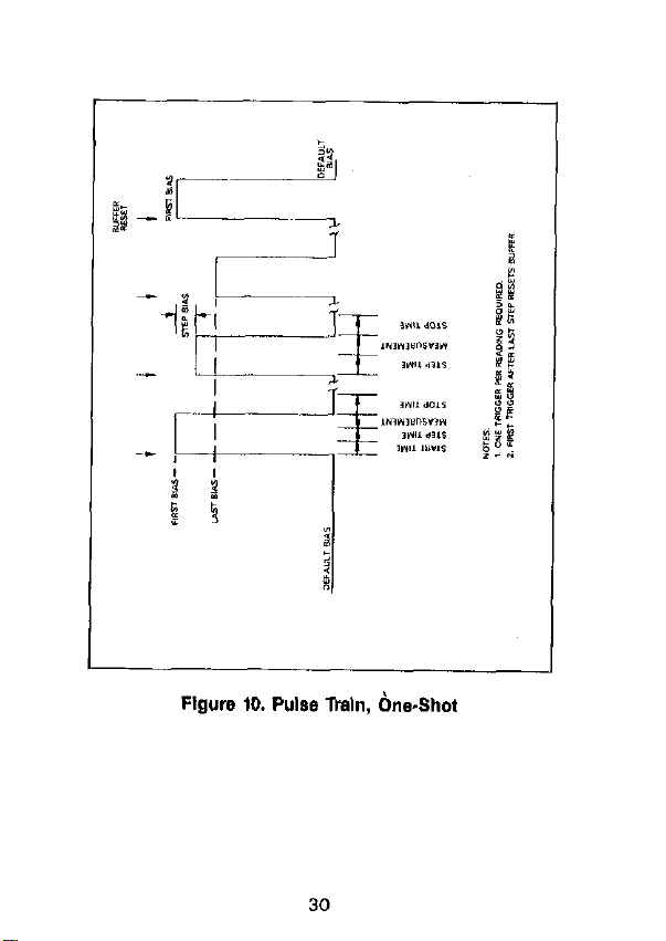
Flgure ID. Pulse lkaln, bne.Shot
30
Page 32

I-
Flgure 11. Pulse lhln, Single SW-P
31
Page 33

Flwm 12. External, OneShot
32
Page 34

Flgure 13. External, SInglO-SWeEP
33
Page 35

IEEE-488 PROGRAMMING
DEVICE-DEPENDENT COMMANDS
Plotter (A)
A0
Al
A2, plot
A3. grid
Plot: O=C YS V: 1 =G YS V;
Z=l/C’w3V; 3=c/c,vsv;
4=c “St; 5=lC,-C,l “9 v;
S=IV,-V.IC=CONST
Grid: 0 = Full grid: 1 = Axis
A4. buffer
A5, pen
AE. line
A7. label
A8.n. Xmin, Xmax
A9.n. Ymin, Ymsx
1 “,%r O=A/D buffer IAl:
1 =Plot buffer @I
Pen: O=No pen; 1 =Pen #I:
2=Pen #2
Line: 0 = DOT at points;
1 = Spaced dots; 2 = Dashes:
3=Long dash: 4=Dash dot;
5=Long dash, short dash;
B=Long, short. long dash;
7=Solid line
Label: O=Full labels; 1 =Label
axls and divisiona; 2 = Label
axis only
X axis limits. n = 0: Autoscsling lminimum/msximum bias).
n = 1: Program X axis
minlmum IXminl and maximum
IXmaxl values.
Y axis limits. n=O: Default
values, 0 to full scale. ” = 1:
Program Y axis minimum
W;;J and maximum fYmaxl
34
Page 36

Save/Recall Cable Setups (C)
C0.n
C1.n
Recall cable #n (Osna71
save csbk #n IOSll56
~
35
Page 37

tm Button (Ii)
Emulate button press:
H12
HI5
H16
HZ0
H23 ZNUAL
H25
HZ6
HZ7
H29 RANGE
H30
H31 MODEL
Cable Parsmeters (I)
IO Measure cable p~mmeter~
Il. “1. “2, “3. “4 Assign cable parameters
12. “1. “2. “3. “4, Assign test output cable
n6, fl6, n7, “6 Ch5tin6L Dh7 tjn6l
13. n1, n2, n3, n4
n5, n6, n7, “6
I:. C, G
IS. C, G
SHIFT
ENTER
(A-6)
ZERO
CAL
FILTER
FRED
(driving point1
KOlnl +jn21, Klln3+jn4)
parameters: Ah1 +jn21.
Bin3+jn4l.
Assign test INPUT cable
parameters: Ah1 +jn2,.
Wn3+in41, Ch5+jn*I
Din7+jn61
Zero cable open
Measure SOlKCB pa,afneterS.
step 1
Measure SOU,CB ,,a,arnefer~.
st*p 2
36
Page 38

Sell
Test
(J)
Jl Perform self test
EOI disabled. hold-off enabled
EOI enabled. hold-off disabled
Bias Control (N)
i’:
t
Bias off
Bias on
37
Page 39
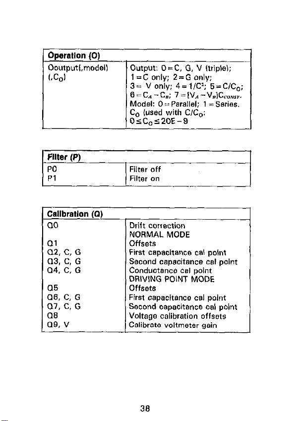
!llter (P)
E
PO
Pl
Callbratlon (a)
00
Ql
Q2. C, G
(13, C. G
Q4. C, G
06
Q6. C, G
07. C. G
cm
a9, v
6 = CA -CL; 7 = IV1 - V.IC,,r.
Model: 0 = Parallel: t = Series.
C, (used with C/C,:
05Co~20E-9
Filter off
Filter on
Drift correction
NORMAL MODE
First capacitance oal point
Second capacitance cal point
Conductance cal point
DRIVING POINT MODE
First capacitance cal point
Second capacitance cal point
Voltage calibration offsets
36
Page 40

I
Range (R)
(100kHr
RO
Rl
R2
R3
R4
R5
R6
R7
R6
R9
Resdlng Rate (S)
so
w 75/set. 3% diuits
si
s3
54
NOTE: Reading rates are nCminal
Autorange on Autorange on
2pF/2pS ZOpFlZOOfiS
ZOpF/ZO,,S
2OOpF/2OOpS 200pF12mS
2nF/2mS
RI x10 on
R2 x10 on EWCf
R3 x10 on EWX
R4 x10 on
Autorange off. stay on range
lOOO/sec, 3% digits
tS/ssc, 4% digits
lO/sec, 4% digits
lisec. 4% digits
1
IMHz
2OpF/200,~S
2nF/20mS
Error
EtKX
One-shot on external pulse
sweep on external pulse
One-shot C” front panel
sweep on front panel
39
Page 41

S
c1
F
Ui
U2
u3
u4
U6
I u9
“10
Ull
U12
u13
u14
u15
Buffer A zen, gr&p
Buffer A bias group
Buffer A bias voltage
Buffer A bias time
Buffer A position and time
Buffer B range group
Buffer B triaaer arouo
Buffer B zero group
Buffer B bias group
Buffer B bias voltage
Buffer B bias time
Buffer B position and times
Buffer A maximum/minimum
cao*citance
Biffer A maximum/minimum
conductance
Buffer A maximum/minimum
Voltage
Buffer 6 maximum/minimum
cepscitance
Buffer 6 msximum/minimum
conductance
Buffer B maximum/minimum
Voltage
Global parameters
fseries/psrallel, Co value)
Plotter parameters lplot, grid,
line, etc.1
IEEE cutput parameters IO, G,
B, Y, KI
IEEE input parameters IL. C, H,
K. MI
40
Page 42

Not used
mnslator reserved word list
Translator NEW/OLD state
First=first bias; Last=last
4=External; Start=start time;
r]OTE: Multiply programmed time6 by 1.024 to obtain BC-
tual times
Execute (X)
X
Execute Commands
41
Page 43

Terminator (Y)
YO
Yl
Y2
Y3
<CR> <LF>
<LF> <CR>
<CR>
<LF>
42
Page 44

L
Flgure 14. Data Format
43
Page 45

44
Page 46

SRQ MASK AND STATUS BYTE FORMAT
Flgure 16. SRQ Mask and Status Byte Format
46
Page 47

UO426 STATUS WORD FORMATS
I
Flgure 17. UO Status Word Format
(Hardwam/Sottware Ftevlslon)
46
Page 48

n
Figure 18. Ul Error Status Word Format
47
-
Page 49

Flgure 19. U2 Status Word Format (Sulfer A Range Group)
Flgure 20. U3 Status Word Format (BufferA lklgger Gmup)
49
Page 50

Figure 21. U4 Status Word Format (Butter A Zero Group)
Flgure 22. U5 Status Word Format (Sutter A Bias Group)
49
Page 51

Flgum 23. LIB Status Word Formal (BufferA Bias Voltages)
50
Page 52

Flgure 24. II7 Status Word Format (Buffer A Bias Times)
Flgure 25. Ug Status Word Format
(Buffer A Posltlon and Time)
51
Page 53

Flgum 26. LIB Status Word Format (Suffer B Range Gmup)
I
Flgum 27. UIO Status Word FOrmat
(Buffer B ltlgger Group)
52
Page 54

Figure 29. U12 Status Word Format (Buffer B 819s Group)
53
Page 55

Flgure 30. U13 Status Word Format
(Butter B Bias Voltages)
Page 56

Figure 31. U14 Status Word Format (Butter B Bias Times)
I
Figure 32. U15 Status Word FOrmat
(Butter B Po8ltlon and The)
55
Page 57

Figure 33. U16 Status Word Fcrmat (Suffer A
Maximum and Mlnlmum Capacitance)
Figure 34. U17 Status Word Format (Buffer A
MaxImum and Mlnlmum Conductance)
56
Page 58

I
Flgure 35. U18 Status Word Fcrmat (Suffer A
Maxlmum and Mlnlmum Voltage)
I
Figure 38. Ul9 Statue WC?d FCrCtCl @Utter B
B Maxlmum and Mlnlmum Capacitance)
67
Page 59

Flgure 37. U20 Status Word Fcrmat (Suffer S
Maxlmum and Mlnlmum Conductance)
Flgure 39. U21 Status Word Fcrmat (Buffer B
MaxImum and Mlnlmum Voltage)
55
Page 60

Figure 39. U22 Statue Word Format
(Global Prog~ittttdng PmVttetem)
59
Page 61

I I
I
Flgurs 40. U23 Statue Word Format
(Plotter Prcgrsmmlng Parameters)
60
I
Page 62

FAA
Figure 4,. U24 StSt”8 Word Format
(IEEE Output PSrSmStSm)
61
Page 63

Flgurs 42. U25 Ststus Word Format
(IEEE Input Psrsmstsrs)
62
Page 64

Flgurs 43. U28 Ststus Word Format
(Cable CorrectIon Psrsmstsrs)
63
Page 65

TRANSLATOR
Table 1. ltsnslstcr Reserved Words and Characters
word or
Character Descrlptlcn
I
ALIAS
NEW
OLD
LIST
FORGET
Define words, enable Translator
Enable Translator, combine words
Disable Translator
Get list of Translator words
Erase Translator words
Terminate Translator definition string
Wildcard to define parameter position
Figure 44. U27 Status Wclrl Format
(Trsnslstcr User Nsms List)
64
Page 66

L
I
I35
Page 67

-
66
Page 68

PROGRAMS
The following programs are designed to be B simple aid to
the usw They are not intended to suit specific needs.
Detailed programming information can be found in the
manual.
67
Page 69

IBM PC or XT
(Keithley Model 8573A Interface)
The following program sends a command string to the
Model 590 from an IBM PC or XT computer and displays
the instrument reading string on the CRT. The computer
must bs equipped with the Keifhley Model 6573A IEEE-469
tnterface and the DOS 2.00 operating system. Model
9573A software must be installed and configured as
described in the inStruction manual.
DIRECTIONS
1. Using the front panel IEEE key. set the primary address
of the Model 590 to 16.
2. With the power off, connect the Model 590 to the
IEEE-496 interface installed in the IBM computer.
3. Type in SASICA on the computer keyboard to get into
the IBM interpretive BASIC language.
4. Place the interface software disc in the default drive, type
LOAD”DECL”. and press the return key.
5. Add the lines below to lines 1-6 which are now in
memory. Modify the address in lines 1 and 2, as described in the Model 6673A Instruction Manual.
6. Run the program and type in the desired command string.
Far example, to place the instrument in autorange and
lMHz frequency, type in ROFlX and press the return
key.
7. The instrument reading string will then appear on the
display. For example, the display might show
NCPM+ 1,2345E- 12.
6. To exit the program, type in EXIT at the command
prompt and press the return key.
66
Page 70

PROGRAM
COMMENTS
Clear screen.
Find board descriptor.
Find instrument
descriptor.
Set primary address to
15.
Set timeouts.
set REN *rUtI.
Prompt for command.
See if program is to be
halted.
Check for null input.
Add space for proper
hold off.
NOTE: For conversion to numeric variable. make the following changes:
130 RD=“AL<MIrJ*<HI!s,SI
15))
135 PKINTRO
69
Page 71

APPLE II (APPLE II IEEE-488 Interface)
The following program sends a command string to the
Model 690 from an Apple II computer and displays the in-
sfrument reading string on the computer CRT.
The computer must be equipped with the Apple II IEEE-488
lnterfsce installed in slot 5. Note that the program 86sumes
;lit&h;, computer is running under Apple DOS 3.3 of
DIRECTIONS
1, Using the front panel IEEE key, 8et the primary address of
the Model 590 to 15.
2. With the ower off. connect the Modal 590 TV the
IEEE-488 interface ik&lled in the Apple II computer.
3. Enter the lines in the progrsm below. using the RETURN
key after each line.
4. Run the program and type in the desired command string
at the command prompt. For example, to place the instrument in the autorange and 1MHz modes, type in
ROFIX and press the return key.
5. The instrument reading string will then appear on the
CRT, A typical display is: NCPK + 1.2345E- 12.
70
Page 72

PROGRAM
1, If conversion to numeric variable is required. make the
following changes:
COMMENTS
-
Terminator.
Define address, slot
variables.
Input command string.
Set oufp”t to IEEE-488
bus.
Define input from
IEEE-488 bus.
Enable remote.
Line feed on.
Address 690 to listen.
send string.
Address 690 to talk.
input data.
Untalk the bus.
Define output to CRT.
Define input from
keyboard.
Display string.
2. The Apple II INPUT statement terminates on commas.
To avoid problems, program the Model 590 for the 01,
02, or 03 data format to eliminate commas.
71
Page 73

HP 85
The fallowing program sends a command string tc the
Model 590 from an HP-95 computer and displays the in-
strwnent reading string on the computer CRT. The com-
puter must be equipped with the HP82937 GPIS Interface
and an l/O ROM.
DIRECTIONS
1. Using the front panel IEEE key, set the primary address
of the Model 590 to 15.
2. With the pcwer off. ccnnect the Model 590 tc the
HPS2937A GPIB interface installed in the HP-86
ccnlpw3,.
3. Enter the lines in the program below, using the END LINE
key after each line.
4. Press the HP-85 RUN ksy and type in the desired ccmmand string at the command prompt. For example, to
place the Instrument in the autorange and 1 MHz modes.
type in ROFlX and press the END LINE key.
5. The instrument reading string will then appear on the
CRT. A typical display is: NCPM + 1.2345E - 12.
72
Page 74
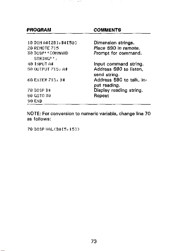
PROGAAM
COMMENTS
Dimension strings.
Place 690 in remote.
Prcmot for command,
Input command string.
Address 590 to listen.
send string.
Address 590 to talk. in-
NOTE: For conversion to numeric variable, change line 70
zls fcllcws:
73
Page 75

HP 9818
The following program sends a command string to the
Model 590 from a Hewlett-Packard Model 9816 ccmpwer
and displays the instrument reading string on the computer
CAT. The computer must be equipped with the HP82937
GPIS Interface and BASICA 2.0.
DIRECTIONS
1, Using the front panel IEEE key. set the primary address
of the Model 590 to 15.
2. With the power off, connect the Model 690 to the
HPS2937A GPIB interface installed in the 9616
computer.
3. Type EDIT and press the EXEC key.
4. Enter the lines in the program below. using the ENTER
key after each line.
5. Press the 9816 RUN key and type in the desired ccmmand string at the command prompt. For example, to
place the instrument In the autorange and IMHz modes,
type in ROFIX and press the ENTER key.
S. The instrument reading string will then appear on the
CRT. A typical display is: NCPM + I .2346E - 12.
74
Page 76

PROGRAM
COMMENTS
Place 590 in remote.
Dimension string.
Prompt far and input
command.
Address 590 to listen,
send string.
Address 590 to talk, input reading.
Display reading string.
Repeat.
NOTE: For conversion to a numeric variable, change the
prcgrsm as fcllcws:
75
Page 77

HP 9825A
Use the following program to send a
the Model 590frcm a Hewlett-Packard Model 9825A and
display the instrument reading string on the computer
printer. The computer must be equipped with the
HP98034A HPIB Interface and a SS72A extended I/O ROM.
DIRECTIONS
1. From the front panel, set the primary address of the
Model 590 to 16.
2. With the power off, connect the Model 590 to the
S8034A HP18 interface installed in the 9925A.
3. Enter the lines in the program below, using the STORE
key after each line. Line numbers are automatically
assigned by the 982%
4. Press the 9825A RUN key and type in the desired ccmmand string at ths command prompt. For example. to
place the instrument in the furorange and 1 MHz modes,
type in ROFlX and press the CONT key.
5. The instrument reading string will then appear on the
computer print cut. A typical display is:
NCPM -1-t .2345E - 12.
command
string to
76
Page 78

PROGRAM
COMMENTS
@dim wL501.B*r201
Dimension data strings.
IdB”“590”,715 Define 590 at address
16.
2 rein* 05% ’ Place 690 in remote.
a mt c C*~,wwO STKIHG’ 3, Prompt for command
Be string.
4 Lvrt ‘540’ ’ I BE
Address 590 to listen.
send string.
5red“598”,** Address 590 to talk, in6 pr* A$
p”, data.
Print data string on
printer.
7 gto 3 RepWat.
NOTE: For conwrsion to numeric variable. modify the program a* follows:
6 prt Val(R%[51)
77
Page 79

DEC LSI 11
The following program sends a command string to the
Model 590 from a DEC LSI 11 minicomputer and displays
the instrument reading string on the DEC CRT terminsl. The
LSI 11 must be configured with f6K words of RAM and
an IBV If IEEE-499 interface. The software must be configured with the I6 software as well as FORTRAN and the
RT 11 operating system.
DIRECTIONS
1. Using the front panel IEEE key, set the primary address
of the Model 590 to 16.
2. With the power off, connect the Model 690 to the IBV
? 1 IEEE-499 interface cable.
3.
Enter ths program below, using the editor under RT 1 1
and the name IEEE.FOR.
4. Compile using the FORTRAN compiler a8 follows: FOR
TRAN IEEE.
5. Link with the system and IB libraries 8s follows: LINK
IEEE,lBLIB.
6. Type RUN IEEE snd press the RETURN key.
7. The display will read “ENTER ADDRESS”.
S.Type in 16 and press the RETURN key.
9. The display will read “TEST SETUP”.
10. Type in the desired command string and press the
RETURN key. For example, to program the instrument
for the autorange and 1 MHz modes, type in ROF 1X and
press RETURN.
11. The instrument data string will appear on the computer
display. A typical display is: NCPM + 1.2345E- 12.
78
Page 80

PROGRAM
COMMENTS
Allow 5 error 15’s.
Allow 1 sscond bus
timeout.
Set line feed 88
terminator.
Turn on remote.
Input primary address.
Prompt for command
string.
79
Page 81
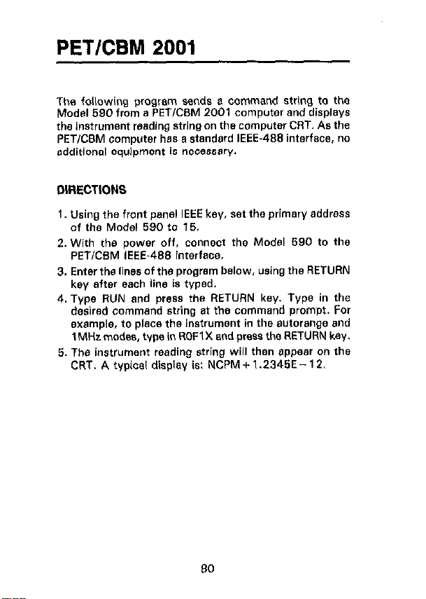
PETKBM 2001
The following program sands a command string to the
Model 690 from a PETKSM 2001 computer and displays
the instrument wading string on the computer CRT. As the
PETlCBM computer has a standard IEEE-498 interface, no
additional equipment is necessw.
DIRECTIONS
1. Using the front panel IEEE key. ?a the primary address
of the Model 590 fo 16.
2. With the power off. connect the Model 590 to the
PETiCBM IEEE-489 interface.
3. Enter the lines of the program below. using the RETURN
key after each line is typed.
4. Type RUN and press the RETURN key. Type in the
desired command string at the command prompt. For
example, to place the instrument in the autorange and
1 MHz modes, type in ROFl X and press the RETURN key.
5. The instrument reading string will then appear on Ihe
CRT. A typical display is: NCPM + 1.2345E- 12.
80
Page 82

PROGRAM
COMMENTS
Open file 1, primary address 15.
Prompt for, input Ccmmand string.
Address 590 tc listen.
send stri”Q.
Address 690 fc talk. inp”t data.
If bus timeout. input
again.
Display reading string.
Repeat.
NOTES:
1. If conversion fc numeric variable is requirsd. modify the
P,OQKW BS fOllOWS:
2. The PET INPUT# statement terminates on a Comma.
Thus. when WadlnQ Model 690 strings which include
ccrntnas, ycu should input each portion of the string intc 8 separate string variable. For example, in the 00
mode, tc obtain and display resdinQs. the program above
CB” be modified as fallows:
81
Page 83

Safety Precautions
The following safety precautions should be observed before
using this product and any associated instrumentation. Although some instruments and accessories would normally
be used with non-hazardous voltages, there are situations
where hazardous conditions may be present.
This product is intended for use by qualified personnel who
recognize shock hazards and are familiar with the safety
precautions required to avoid possible injury. Read and follow all installation, operation, and maintenance information
carefully before using the product. Refer to the manual for
complete product specifications.
If the product is used in a manner not specified, the protection provided by the product may be impaired.
The types of product users are:
Responsible body
the use and maintenance of equipment, for ensuring that the
equipment is operated within its specifications and operating
limits, and for ensuring that operators are adequately trained.
Operators
must be trained in electrical safety procedures and proper use
of the instrument. They must be protected from electric
shock and contact with hazardous live circuits.
Maintenance personnel
product to keep it operating properly, for example, setting the
line voltage or replacing consumable materials. Maintenance
procedures are described in the manual. The procedures explicitly state if the operator may perform them. Otherwise,
they should be performed only by service personnel.
Service personnel
perform safe installations and repairs of products. Only
properly trained service personnel may perform installation
and service procedures.
Keithley products are designed for use with electrical signals that are rated Installation Category I and Installation
is the individual or group responsible for
use the product for its intended function. They
perform routine procedures on the
are trained to work on live circuits, and
5/02
Page 84

Category II, as described in the International Electrotechnical Commission (IEC) Standard IEC 60664. Most measurement, control, and data I/O signals are Installation Category
I and must not be directly connected to mains voltage or to
voltage sources with high transient over-voltages. Installation Category II connections require protection for high
transient over-voltages often associated with local AC mains
connections. Assume all measurement, control, and data I/O
connections are for connection to Category I sources unless
otherwise marked or described in the Manual.
Exercise extreme caution when a shock hazard is present.
Lethal voltage may be present on cable connector jacks or
test fixtures. The American National Standards Institute
(ANSI) states that a shock hazard exists when voltage levels
greater than 30V RMS, 42.4V peak, or 60VDC are present.
A good safety practice is to expect that hazardous voltage
is present in any unknown circuit before measuring.
Operators of this product must be protected from electric
shock at all times. The responsible body must ensure that
operators are prevented access and/or insulated from every
connection point. In some cases, connections must be exposed to potential human contact. Product operators in these
circumstances must be trained to protect themselves from
the risk of electric shock. If the circuit is capable of operating at or above 1000 volts,
cuit may be exposed.
Do not connect switching cards directly to unlimited power circuits. They are intended to be used with impedance limited
sources. NEVER connect switching cards directly to AC
mains. When connecting sources to switching cards, install
protective devices to limit fault current and voltage to the card.
Before operating an instrument, make sure the line cord is
connected to a properly grounded power receptacle. Inspect
the connecting cables, test leads, and jumpers for possible
wear, cracks, or breaks before each use.
When installing equipment where access to the main power
cord is restricted, such as rack mounting, a separate main input power disconnect device must be provided, in close proximity to the equipment and within easy reach of the operator.
no conductive part of the cir-
Page 85

For maximum safety, do not touch the product, test cables,
or any other instruments while power is applied to the circuit
under test. ALWAYS remove power from the entire test system and discharge any capacitors before: connecting or disconnecting cables or jumpers, installing or removing
switching cards, or making internal changes, such as installing or removing jumpers.
Do not touch any object that could provide a current path to the
common side of the circuit under test or power line (earth)
ground. Always make measurements with dry hands while
standing on a dry, insulated surface capable of withstanding the
voltage being measured.
The instrument and accessories must be used in accordance
with its specifications and operating instructions or the safety of the equipment may be impaired.
Do not exceed the maximum signal levels of the instruments
and accessories, as defined in the specifications and operating information, and as shown on the instrument or test fixture panels, or switching card.
When fuses are used in a product, replace with same type
and rating for continued protection against fire hazard.
Chassis connections must only be used as shield connections for measuring circuits, NOT as safety earth ground
connections.
If you are using a test fixture, keep the lid closed while power is applied to the device under test. Safe operation requires
the use of a lid interlock.
If or is present, connect it to safety earth ground
using the wire recommended in the user documentation.
!
The symbol on an instrument indicates that the user
should refer to the operating instructions located in the manual.
The symbol on an instrument shows that it can source
or measure 1000 volts or more, including the combined effect
Page 86

of normal and common mode voltages. Use standard safety
precautions to avoid personal contact with these voltages.
The
WARNING
might result in personal injury or death. Always read the associated information very carefully before performing the
indicated procedure.
The
CAUTION
could damage the instrument. Such damage may invalidate
the warranty.
Instrumentation and accessories shall not be connected to
humans.
Before performing any maintenance, disconnect the line
cord and all test cables.
To maintain protection from electric shock and fire, replacement components in mains circuits, including the power
transformer, test leads, and input jacks, must be purchased
from Keithley Instruments. Standard fuses, with applicable
national safety approvals, may be used if the rating and type
are the same. Other components that are not safety related
may be purchased from other suppliers as long as they are
equivalent to the original component. (Note that selected
parts should be purchased only through Keithley Instruments to maintain accuracy and functionality of the product.) If you are unsure about the applicability of a
replacement component, call a Keithley Instruments office
for information.
To clean an instrument, use a damp cloth or mild, water based
cleaner. Clean the exterior of the instrument only. Do not apply cleaner directly to the instrument or allow liquids to enter
or spill on the instrument. Products that consist of a circuit
board with no case or chassis (e.g., data acquisition board for
installation into a computer) should never require cleaning if
handled according to instructions. If the board becomes contaminated and operation is affected, the board should be returned to the factory for proper cleaning/servicing.
heading in a manual explains dangers that
heading in a manual explains hazards that
Page 87

Specifications are subject to change without notice.
All Keithley trademarks and trade names are the property of
Keithley Instruments, Inc. All other trademarks and trade names
are the property of their respective companies.
Keithley Instruments, Inc.
28775 Aurora Road • Cleveland, Ohio 44139
440-248-0400 • Fax: 440-248-6168
1-888-KEITHLEY (534-8453) www.keithley.com
© Copyright 2000 Keithley Instruments, Inc.
Printed in the U.S.A. 04/2001
 Loading...