

Page 1

Model 5802
IEEE-488 Interface
Instruction Manual
Contains Operating and Servicing Information
Page 2

WARRANTY
Keithley Instruments, Inc. warrants this product to be free from defects in material and workmanship for a period of 1 year from date of
shipment.
Keithley Instruments, Inc. warrants the following items for 90 days from the date of shipment: probes, cables, rechargeable batteries,
diskettes, and documentation.
During the warranty period, we will, at our option, either repair or replace any product that proves to be defective.
To exercise this warranty, write or call your local Keithley representative, or contact Keithley headquarters in Cleveland, Ohio, You will
be given prompt assistance and return instructions. Send the product, transportation prepaid, to the indicated service facility. Repairs
will be made and the product returned, transportation prepaid. Repaired or replaced products are warranted for the balance of the original warranty period, or at least 90 days.
LIMITATION OF WARRANTY
This warranty does not apply to defects resulting from product modification without Keithley’s express written consent, or misuse of
any product or part. This warranty also does not apply to fuses, software, non-rechargeable batteries, damage from battery leakage, or
problems arising from normal wear or failure to follow instructions.
THIS WARRANTY IS IN LIEU OF ALL OTHER WARRANTIES, EXPRESSED OR IMPLIED, INCLUDING ANY IMPLIED
WARRANTY OF MERCHANTABILITY OR FITNESS FOR A PARTICULAR USE. THE REMEDIES PROVIDED HEREIN ARE
BUYER’S SOLE AND EXCLUSIVE REMEDIES.
NEITHER KEITHLEY INSTRUMENTS, INC. NOR ANY OF ITS EMPLOYEES SHALL BE LIABLE FOR ANY DIRECT, INDIRECT, SPECIAL, INCIDENTAL OR CONSEQUENTIAL DAMAGES ARISING OUT OF THE USE OF ITS INSTRUMENTS AND
SOFTWARE EVEN IF KFJTHLEY INSTRUMENTS, INC., HAS BEEN ADVISED IN ADVANCE OF THE POSSIBILITY OF
SUCH DAMAGES. SUCH EXCLUDED DAMAGES SHALL INCLUDE, BUT AR!? NOT LIMITED TO: COSTS OF REMOVAL
AND INSTALLATION, LOSSES SUSTAINED AS THE RESULT OF INJURY TO ANY PERSON, OR DAMAGE TO PROPERTY.
Page 3

Model 5802 IEEE-488 Interface
Instruction Manual
0 1985, Keithley Instruments, Inc.
Test Instrumentation Group
All rights reserved.
Cleveland, Ohio, U.S.A.
July 1987, Second Printing
Document Number: 5802-901-01 Rev. 6
Page 4

Safety Precautions
The following safety precautions should be observed before
using this product and any associated instrumentation. Although sane instruments and accessories would normally be
used with non-hazardous voltages, there are situations where
hazardous conditions may be present.
This product is intended for use by qualified personnel who
recognize shock hazards and are familiar with the safety pre-
cautions required to avoid possible injury. Read the operating
information carefully before using the product.
Exercise extreme caution when a shock hazard is present. Lethal voltage may be present on cable connector jacks or test
fixtures. The American National Standards Institute (ANSI)
states that a shock hazard exists when voltage levels greater
than 3OV RMS, 42.4V peak, or 60VDC are present. A good
safety practice is to expect that hazardous voltage is present
in any unknown circuit before measuring.
Before operating an instrument, make sure the line cord is
connected to a properly grounded power receptacle. Inspect
the connecting cables, test leads, and jumpers for possible
wear, cracks, or breaks beforr each use.
For maximum safety, do not touch the product, test cables, or
any other instruments while power is applied to the circuit
under test. ALWAYS remove power from the entire test system and discharge any capacitors before: connecting or disconnecting cables or jumpers, installing or removing
switching cards, or making internal changes, such as installing or removing jumpers.
Do not touch any object that could provide a current path to
the common side of the circuit under test or power line
(earth) ground. Always make measurements with dry bands
while standing on a dry, insulated surface capable of with-
standing the voltage being measured.
Do not exceed the maximum signal levels of the instruments
and accessories, as defined in the specifications and operating
information, and as shown on the instrument or test fixture
rear panel, or switching card.
Do not connect switching cards directly to unlimited power
circuits. They are intended to be used with impedance limited sources. NEVER connect switching cards directly to AC
main. When connecting sources to switching cards, install
protective devices to limit fault current and voltage to the
card.
When fuses are used in a product, replace with same type and
rating for continued protection against fire hazard.
Chassis connections must only be used as shield connections
for measuring circuits, NOT as safety earth ground connections.
If you are using a test fixture, keep the lid closed while power
is applied to the device under test. Safe operation requires the
use of a lid interlock.
If a @screw is present on the test fixture, connect it to safety
earth ground using #18 AWG or larger wire.
The $ symbol on an instrument or accessory indicates that
1OOOV or more may be present on the terminals. Refer to the
product manual for detailed operating information.
Instrumentation and accessories should not be connected to
humans.
Maintenance should be performed by qualified service personnel. Before performing any maintenance, disconnect the
line cord and all test cables.
Page 5

SPECIFICATIONS/5802
ANALOG OUTPUT
LEVEL: 1” = 10,cal CO”“tS 0” Xl gain.
1” = 100 Counts on Xl00 gain,
Maximurn output voltage = *‘iv.
ACC”RACY: *(0.25% 0, displayed reading +*r”“)~ In x100. 2mV
output = 0.2 displayed aunts.
:EEE-488 BUS IMPLEMENTATION
RESPONSE TIME: FdlOWS d,splay cnnversion rate,
OUTPUT RESISTANCE: 1OOOn~
ISOLATION: ANALOC; OUTPUT LO is connected to ,EEE COM-
MON. Maximum cwnmo” mode voltage from IEEE COMMON to
earth ground is 3W rms al dc. 50 or 6011~~
.l”l.T,LINE COMMANDS: DCL. SK, GET. GTL. UNT. UNL.
WE. 3’“. LLO,
lN,L,NE COMMANDS: IFC, EN, EOI, SRQ, ATN,
NTERFACE FUNCTIONS: SHl. AH,. T5, TEO. L4. LEO, SRI. RLO.
PPO. DC,, DT,, CU. El.
‘ROCRAMMABLE PARAMETERS: Range. DRY CIRCUIT
TEST,Operate, RELative. POLARITY, DRIVE. TRlCger. Calibra-
tian. EOI, SRQ. Status. Data Format. Terminatar~
,E”,CE-DEPENDENT COMMANDS:
RANGE:
RO
;:
R-3 20 n
114 200 n
R5 2k n
Rb 2Ok n
R7 200k n
RELATIVE:
ZO = REL ofi
Z, = REL on
OPERATE:
0” = STBY (Standby1
0, = OPR (Operatv)
POLARITY:
PO = FOL +
Pi = I’OL -
DRIVE:
DO = DRIVE (puked)
D, = DRIVE
DRY ClRCUIT TEST:
CO = NON DRY CIRCUIT TEST
C, = DRY CIRCUIT TEST
D,G,TAL CALIBRATION:
v * n.nn,,,,~ * nn = enter calibratiun value.
STORE:
LO = Store calibration constants.
NON
DRY CIRCUIT
TEST
A”to
2”“rnII
2 R
(dc)
DRY CIRCUIT
TEST
Auto
2OOmll
2 0
20 0
20 0
20 n
20 0
20 0
TRIGGER:
TO = Continuous on Talk
T, = One-shot on Talk
T2 = Continuous ~1” GET
T3 = O”e~shr,t <>n GET
T4 = Cantinuous on X
TZ = One-shut on X
EXECUTE:
X = Exerute drviwdcprndent cwnmands
EO,:
KO = EOI Enabled
K1 = EO, “isabied
STATUS WORD:
ti” = Ourput status word,
DATA FORMAT:
GO = Readings and status word with preiix
C, = Readings and status word withut pretix
SRQ:
MO = Clear SRQ Data Mask
MI = Reading Overthn%
MS i Reading D”“r
M9 = Reading Done or Reading Ovcrfh
Ml6 = BUS)
M,, = Busy ,,T Reading Overflw
M24 = Busy or Reading Dane
M25 = Busy. Reading hne i)r Reading Overflw
M32 = Clear SRQ Ermr Mask
M33 = IDDCO
M34 = IDDC
M3S = ,DDC or IDDCO
M36 = Not in Remote
,437 = Not in Remok or ,DDCCl
M3X = Not in Rem<>tr or ,D,,C
M39 = Not in Remote. lDDC or (“DC0
TERMINATOR:
Y(ASC,I) = ASCII Character
Y(LF) = CR LF
Y(CR) = LF CR
Y(DEL, = None
T,ME FROM TRlGGER TO FlRST BYTE OUT: 350”~s 10 500ms.
ADDRESS MODES: Taik Only. Addressable
Page 6

DATA FORMAT AND STATUS BYTE OUTPUT
DATA FORMAT: STATUS BY-I-E OUTPUT:
TERMINATOR I
EXPONENT
PREF’X -FL u-l
N + DP + I.23456 E + 2 ,cR)(LF,
(pulsed)
D = DRIVE
S=STANDBY J L
N = NORMAL
O=OVERFLOW D=DRY
Z = RELATIVE CIRCUIT TEST
DRY CIRCUIT TEST: N = NON DRY
!-
POLARITY: + = POL +
- =POL -
id4
CIRCUIT TEST
580 D P C 0 R Z K T Md Me H Y
RELATIVE
TRIGGER
SRQ ON DATA
SRQ ON ERROR
LINE FREQUENCY A
TERMINATOR
I
PREFIX
DRIVE
POLARITY
DRY CIRCUIT TEST
OPERATE
RANGE
EOI
Page 7

TABLE OF
SECTION l-GENERAL INFORMATION
CONTENTS
1.1
1.2
1.3
1.4
1.5
1.6 USING THE INSTRUCTION MANUAL
1.7
1.8 UNPACKING AND INSPECTION..
INTRODUCTION
INTERFACE FEATURES
WARRANlY INFORMATION
MANUAL ADDENDA
SAFETY SYMBOLS AND TERMS
SPECIFICATIONS
......
......
......
......
......
......
......
SECTION 2-AN OVERVIEW OF THE IEEE-488 BUS
2.1 INTRODUCTION
2.2
2.3 IEEE-488 BUS LINES
2.3.1 BusManagement Lines
2.3.2 Handshake Lines
2.3.3 Data Lines
2.4 BUS COMMANDS
2.4.1
2.4.2
2.4.3 Addressed Commands
2.4.4 Unaddressed Commands
2.4.5 Device-Dependent Commands
2.5
2.6 COMMAND SEQUENCES
2.6.1 Addressed Command Sequence
2.6.2
2.6.3 Device-Dependent Command Sequence ......................................................
BUS DESCRIPTION
UniIine Commands
Universal Commands
COMMAND CODES
Universal Command Sequence
............................................................................
..........................................................................
.........................................................................
.....................................................................
...........................................................................
.................................................................................
...........................................................................
.........................................................................
.......................................................................
......................................................................
...................................................................
..............................................................
.........................................................................
...................................................................
............................................................. 2-7
..............................................................
......
......
......
......
......
......
......
......
......
......
......
......
......
......
......
......
..,...
1-l
1-l
1-l
1-l
1-l
1-l
l-2
l-2
2.1
2-l
2-2
2-2
2-2
2-3
2.3
2-4
2-4
2-5
2-5
2-5
2.5
2-7
2-8
2-8
SECTION 3-SYSTEM CONFIGURATION
3.1 INTRODUCTION
3.2 HARDWARE CONSIDERATIONS .............................................................
3.2.1 Typical Systems
3.2.2 Bus Connections
3.2.3 Primary Address Selection..
3.3
3.3.1 Controller Interface Routines
3.3.2 HP-85BASIC Statements
3.3.3 InterfaceFunction Codes ....................................................................
3.3.4 Interface Commands
SOFTWARE CONSIDERATIONS .............................................................
............................................................................
............................................................................
...........................................................................
................................................................
................................................................
...................................................................
.......................................................................
3-l
3-l
3-l
3-2
3-4
3-5
3-5
3-5
3-6
3-7
I
Page 8

SECTION 4-OPERATION
4.1
4.2
4.2.1
4.2.2
4.2.3
i.2.4
4.2.5
4.2.6
4.2.7
4.3
4.3.1
4.3.2
4.3.3
4.3.4
4.3.5
4.3.6
4.3.7
4.3.8
4.3.9
4.3.10
4.3.11
4.3.12
4.3.13
4.3.14
4.3.15
4.4
INTRODUCTION ..............
GENERAL BUS COMMANDS
REN (Remote Enable). ........
IFC (Interface Clear) ..........
GTL (Go To Local) ...........
LLO (Local Lockout). .........
DCL (Device Clear). ..........
SDC (Selective De&ce Clear)
Serial Polling (SPE, SPD)
DEVICE-DEPENDENT COMMAND PROGRAMMING..
Execute(X) ..........................
Range (R) ...........................
Operate/Standby (0) .................
Dry Circuit Test (C) ..................
Relative (2). .........................
Digital Calibration (V) and Storage (L)
Polarity (P) ..........................
Drive (D) ............................
Triggering (T) ............................
EOI (K) .................................
SRQ Mode (M) and Status Byte Format ....
Status Word (U) or Alternate Output ......
Prefix(G)
Programmable Terminator (Y) .............................................................. 4-14
Data Format .............................................................................. 4.14
TALK ONLY OPERATION ..................................................................
.................................................................................
.......
.......
.......
.......
.......
.......
......
......
......
......
......
......
..........
..........
..........
..........
..........
..........
..........
.................................................
.................................................
.................................................
................................................
......
......
......
......
......
......
......
......
......
......
......
......
......
......
......
......
4-l
4-l
4-l
4-2
4-2
4-2
4-3
4-3
4-3
4-4
4-b
4-6
4-6
4-6
4-7
4-7
4-8
4-8
4-8
4-8
4-9
4-13
4-13
4.15
SECTION 5-ANALOG OUTPUT
5.1
5.2
5.3
5.4
INTRODUCTION ............................................................................
USING THE ANALOG OUTPUT .............................................................
OUTI’UTRESISTANCE ......................................................................
Xl00 RESOLUTION AND ACCURACY
........................................................
SECTION 8-PRINCIPLES OF OPERATION
6.1
6.2
6.2.1
6.2.2 Digital Circuitry..
6.2.3
INTRODUCTION ............................................................................
CIRCUIT DESCRIPTION .....................................................................
Power Supply .............................................................................
..........................................................................
Analog Output .............................................................................
SECTION 7-MAINTENANCE
7.1
7.2
7.3
7.3.1
7.3.2
7.3.3
7.3.4 Calibration. ................................................................................
7.4 SPECIAL HANDLING OF STATIC-SENSITIVE DEVICES
7.5 TROUBLESHOOTING
INTRODUCTION ............................................................................
INSTALLATION .............................................................................
CALIBRATION ..............................................................................
Warm Up .................................................................................
Recommended Calibration Equipment ........................................................
Environmental Conditions ..................................................................
.......................................................................
.......................................
5-l
5-l
5-3
5-3
b-1
6-l
6-l
6-2
6-2
7-l
7-l
7-l
7-l
7-l
7-3
7-3
7-3
7-3
ii
Page 9

SECTION 8--REPLACEABLE PARTS
8.1
8.2
8.3
8.4
8.5
INTRODUCTION ............................................................................
REPLACEABLE PARTS.
ORDERING INFORMATION
FACTORY SERVICE
SCHEMATIC DIAGRAMS AND COMPONENT LOCATION DRAWINGS
......................................................................
.................................................................
.........................................................................
8-l
8-l
8-1
8-l
........................ 8-1
iii
Page 10

LIST OF TABLES
SECTION 2-AN OVERVIEW OF THE IEEE-488 BUS
2-l
2-2
2-3
2-4
IEEE-488 Bus Command Summary .,,,...,,.._...,,,.,..,,,._..................,,............. 2-4
Hexadecimal and Decimal Command Codes.. 2-7
Typical Addressed Command Sequence.. 2-8
Typical Device-Dependent Command Sequence 2-8
SECTION 3-SYSTEM CONFIGURATION
3-l
3-2
3-3
3-4
3-5
IEEE-488 Contact Designations
Primary Address Switch Positions
HP-85 IEEE-488 BASIC Statement
Interface Function Codes
IEEE-488 Command Groups
................................................................
.............................................................
.............................................................
.......................................................
..................................................................
SECTION 4-OPERATION
4-l
4-2
4-3
4-4
4-5
4-6
GeneralBus Commands
Default Values (Status Upon Power Up or After SDC or DCL).
Device-Dependent Command Summary
RangeCommands
SRQMask Commands
Status Byte and Mask Interpretation
......................................................................
........................................................
...........................................................................
.......................................................................
..........................................................
SECTION t&ANALOG OUTPUT
5-l AnalogOutputParameters....................................................................
..................................
.............
3-3
3-4
3-6
3-7
3-7
4-l
4-4
4-5
4-6
4-9
4-10
5-3
SECTION 7--MAINTENANCE
7-1 Static SensitiveDevices.......................................................................
7-2 Model5802InterfaceChecks..................................................................
SECTION 8-REPLACEABLE PARTS
8-l
iv
Model5802Parts List _...._.........................._.,.,.___.,...._.._.__._................ 8-2
7-3
7-4
Page 11

LIST OF ILLUSTRATIONS
SECTION 2-AN OVERVIEW OF THE IEEE-488 BUS
2-l
2-2
2-3
IEEE-488 Bus Configuration ...... .. ......................... ..................... 2-l
Handshake Sequence
Command Codes ............ _......
.........................................................................
SECTION 3-SYSTEM CONFIGURATION
3-l SystemTypes
3-2 IEEE-488 Connector
3-3 IEEE-488 Connections
3-4
3-5
3-6
3-7
Contact Assignments
Rear Panel of Model 580 Showing IEEE-488 Connections and Switches
Typical IEEE-488 Bus Drive (one of 16).
Primary Address Switch (Address 25 Shown)
......................................................
.................................................
...............................................
................................................
SECTION 4-OPERATION
4-l Status Byte Format
4-2
4-3
General Format for UO Command
Data Format
..........................................................................
............................................................
................................................................................
SECTION 5-ANALOG OUTPUT
5-l
5-2
5-3
Analog Output Connections
Xl Analog Output ........................................................................... 5-2
XlOOAnalog Output .._ ...................................................................... 5-3
..................................................................
........................................................
...............................
.........................
2-3
2-6
3-l
3-2
3-2
3-2
3-3
3-3
3-4
4-10
4-11
4-14
5-l
SECTION 6-PRINCIPLES OF OPERATION
6-l
6-2
6-3
Simplified Block Diagram.. ................................................................... 6-l
Memory Map
Xland Xl00 Gains ........................................................................... 6-3
................................................................................
SECTION 7-MAINTENANCE
7-l
Model 5802 Installation
.......................................................................
SECTION 8-REPLACEABLE PARTS
8-l
8-2
Model 5802 Interface, Component Location Drawing, Dwg. No. 5802-100
Model 5802 Interface, Schematic Diagram, Dwg. No. 5802-106
6-2
7-2
......................... 8-4
................................... 8-5
Page 12

SECTION 1
GENERAL INFORMATION
1.1 INTRODUCTION
The Model 5802 is an IEEE-488 interface for the Model 580
Micro-ohmmeter. This interface, which includes analog
output, adds extra versatility to the Model 580 by allowing the transmission of data and commands over the
IEEE-488 bus. The interface provides all the necessary logic
to interface the Model 580 to the bus using standard
IEEE-488-1978 protocol.
1.2 INTERFACE FEATURES
Important IEEE-488 interface features:
l With the Model 5802 installed, the Model 580 is able to
communicate with other insrmmentation using the same
IEEE-488s1!778 standards.
l A standard IEEE-488 connector that provides easy con-
nection to the IEEE-488 bus.
l An easily-changeable primary address. Although the
Model 580 is shipped from the factory with a primary
address of 25, the customer can change it by using the
five rear panel address switches.
l All Model 580 operation is supported by IEEE-488 pro-
gramming. In addition, numerous other IEEE-488 commands add operating features not available from the front
pSW1.
1.4 MANUAL ADDENDA
Information concerning improvements or changes to the
instrument which occur after the printing of this manual
may be found on an addendum included with this
manual. Review these changes before programming the
Instrument.
1.5 SAFETY SYMBOLS AND TERMS
The following safety symbols and terms are used in this
manual and may be found on the instrument.
The A symbol on the instrument indicates that the user
should refer to the operating instructions.
Information associated with the WARNING heading explains dangers that could result in personal injury or
death.
Information following the CAUTION heading explains
hazards that could damage the instrument.
1.6 USING THE INSTRUCTION MANUAL
1.3 WARRANTY INFORMATION
Warranty information may be found on the inside front
cover of this manual. Should it become necessary to exercise the warranty, contact your Keithley representative or
the factory to determine the proper course of action.
Keithley Instruments, Inc. maintains service facilities in the
United States, the United Kingdom and throughout
Europe. Addresses for these facilities may be found inside
the front cover of this manual. Information concerning the
application, operation or service of your instrument may
be directed to the applications engineer at any of these
locations.
This manual contains all the information you need to con-
nect the Model 5802 to the IEEE-488 bus and program the
instrument from a separate bus controller.
The manual is divided into the following sections:
1. Section 2 contains a general description of the IEEE-488
bus and its commands.
2. Section 3 contains information necessary to connect the
instrument to the bus and set the primary address.
3. Section 4 contains the bulk of the programming information. General bus commands as well as commands
unique to the Model 5802 are covered in detail.
1-l
Page 13

4. Section 5 explains the analog output feature of the
Model 5802.
5. Section 6 contains Principles of Operation.
6. Section 7 contains maintenance information such as installation and troubleshooting.
7. Section 8 contains replaceable parts information and applicable schematics and component layouts.
and electrically before shipment. When the Model 5802
arrives, carefully unpack all items and check for any obvious signs of damage.
Report any damage to the shipping agent immediately. Retain and use the original packing material in case reshipment is necessary. The following items are shipped with
every Model 5802 order:
1.7 SPECIFICATIONS
A complete list of IEEE-488 specifications can be found
preceding this section.
1.8 UNPACKING AND INSPECTION
The Model 5802 was carefully inspected both mechanically
Model 5802 IEEE-488 Interface
Hardware necessary for installation
Model 5802 Instruction Manual
Additional accessories as ordered
If you need another manual, order the manual package
(Keithley Part No. 5802-901-01). This package includes an
instruction manual and any pertinent addenda.
l-2
Page 14

2.1 INTRODUCTION
SECTION 2
AN OVERVIEW OF THE IEEE-488 BUS
The IEEE-488 bus is an instrumentation data bus adopted
by the IEEE (Institute of Elechical and Eleckonic Engineers)
in 1975 and given the IEEE-488 designation. The most recent revision of bus standards was made in 1978; hence
the complete description for current bus standards is the
IEEE-488-1978 designation.
The information presented here is not an elaborate description of a complicated set of standards. Rather, this section
briefly describes general bus structure including a bus command outline. Complete IEEE-488 bus information is
available from the IEEE and other sources.
2.2 BUS DESCRIPTION
The IEEE-488 bus is a parallel data transfer medium that
optimizes data transfer without using an excessive number
of bus lines. The bus has only eight data lines, used for
data and certain commands. In addition, the IEEE-488 bus
employs eight signal lines, including five bus management
lines and three handshake lines. Since the bus is of pamlIe
design, all devices connected to the bus have the same in-
formation available simultaneously. Each device processes
information received from the bus depending on its
capabilities.
TO OTHER DEVlCES
/ * \
DATA BYTE
TRANSFER
CONTROL
INTERFACE
T
HANDSHAKE
A typical bus configuration for controlled operation is
shown in Figure 2-l. A typical system has one controller
and one or more instruments that receive commands and
which usually yield data.
BUS
MANAGEMENT
Figure 2-1. IEEE-488 Bus Configuration
2-1
Page 15

AN OVERVIEW OF THE IEEE-488 BUS
Three categories described device operation: controller,
talker, and listener. The controller regulates other devices
on the bus, the talker sends data, and the listener receives
data. A particular device may be a talker only or both a
talker and a listener. A system can have only one controller
(although control may be passed on to an appropriate
device through a special command). Several talkers and
listeners may be present depending on the bus’s
capabilities.
The bus is limited to 15 devices including the controller.
The maximum cable length is 20m.
Several devices may listen simultaneously, but only one
device at a time may be a talker. Otherwise, communication would be garbled.
Before a device can be a talker or a listener, it must be appropriately addressed. Devices are selected according to
their primary address; the addressed device is sent a talk
or listen command derived from its primary address. Each
device on the bus has a unique address so that each may
be addressed individually.
ATN (Attention)-The ATN line is an important management line. ATN line status indicates if controller information on the data bus is to be considered data (set high false)
or a multiline command (set low).
IFC (Interface Clear)-The IFC line, set true (low), sends
the bus to a known state by sending the IFC command.
REN (Remote Enable)-The REN line, set low, sets up in-
struments on the bus for remote operation.
EOI (End or Identify)-The EOI line, set low, sends the
command to terminate a multi-byte transfer sequence.
SRQ (Service Request)-The SRQ line is set low by a device
when it requires service from the controller.
2.3.2 Handshake Lines
The bus uses three handshake lines that operate in an interlocked sequence. This method ensures reliable data
transfer regardless of the transfer rate. Generally, the
slowest active device on the bus determines the data
transfer rate.
Once a device is addressed to talk or listen, appropriate
bus transactions take place. For example, if an instrument
is addressed to talk, it sends its data to the bus one byte
at a time. The listening device reads this information, and
the appropriate software is then used to channel the information to the desired location.
2.3 IEEE-488 BUS LINES
Three types of signal lines are found on the IEEE-488 bus
lines: data lines, which handle bus information, and handshake and bus management lines, which ensure proper
data transfer and bus operation. Each of these bus lines
is “active low” so that approximately zero (0) volts is a logic
one (1). The following paragraphs describe the purpose
of these lines, which are illustrated in Figure 2-l.
2.3.1 Bus Management Lines
The bus management group includes five signal lines that
ensure orderly data transfer. These lines send the uniline
commands described in paragraph 2.4.1.
Of the three bus handshake lines, the data source controls
one and the accepting device controls the other two. The
handshake lines are:
DAV (Data Valid)-The source controls the state of the DAV
line.
NRFD (Not Ready For Data)-The acceptor controls the
state of the NRFD line.
NDAC (Not Data Accepted)--The acceptor controls the state
of the NDAC line.
Figure 2-2 illustrates the complete handshake sequence for
one data byte. Once data is on the bus, the source confirms that NRFD is high, indicating that all devices on the
bus are ready for data. Simultaneously, NDAC is low from
the previous byte transfer. If these conditions are not met,
the source must wait until the NRFD and NDAC lines have
the correct status. If the source is a controller, NRFD and
NDAC must remain stable for at least 1OOnsec after ATN
is low. Some controllers have time-out routines to display
error messages if the handshake sequence stops for any
reason to reduce the possibility of bus hang-up.
2-2
Page 16

DATA
DAV
X
SOURCE
SOURCE
AN OVERVIEW OF THE IEEE-488 BUS
DAV line high, indicating bus data is invalid, and the
NDAC line returns to its low state. Finally, each of the
devices releases the NRFD line at its own rate until it goes
high when the slowest device is ready. The bus is then set
to repeat the sequence with the next data byte.
MRFD
NOAC
VALlD
I
I I
I
I
I
I
I
I
DAiA
TRANSFER
BE61N
I
I
1
I
I
OAt A
TRANBFER
END
ACCEPTOR
ACCEPTOR
Figure 2-2. Handshake Sequence
Once the NRFD and NDAC lines are properly set, the
source sets the DAV line low (data on the bus is now valid).
The NRFD line then goes low, and the NDAC line goes
high after all devices on the bus have accepted the data.
Each device releases the NDAC line at its own rate. The
NDAC line will not go high until the slowest device has
accepted the data byte.
After the NDAC line goes high, the source then sets the
2.3.3 DBtB Lines
The IEEE-488 bus uses eight data lines that allow data to
be transmitted and received in a bit-parallel, byte-serial
manner. The eight lines are labeled DIOl through DI08, are
bidirectional and, as with the remaining bus signal lines,
low is true.
2.4 BUS COMMANDS
This section briefly describes the purpose of the bus commands that control communication between various instruments on the bus. The commands can be divided into
three categories.
Uniline Commands-Sent by setting the associated bus
line low.
Multiline Commands-General bus commands which are
sent over the data lines with the ATN line low.
Device-dependent Commands-Special commands that
depend on device configuration; sent over the data lines
with ATN high.
2-3
Page 17

AN OVERVIEW OF THE IEEE-488 BUS
Table 2-1. IEEE-488 Bus Command Summary
-I-
Command Type
Uniline
Command
REN (Remote Enable)
EOI (End Or Identify)
IFC (Interface Clear)
ATN (Attention)
SRQ (Service Request)
Multiline
Universal
DCL (Device Clear)
WE (Serial Poll Enable)
SI’D (Serial Poll Disable)
Addressed
SDC (Selective Device Clear)
GTL (Go To Local)
GET (Group Execute Trigger)
Unaddressed
UNL (Unlisten)
UNT (Untalk)
Device-dependent**
*X = Don’t Care
*‘See paragraph 4.3 for complete description.
State of
ATN Line*
i
t
X
X
X
Low
X
Low
Low
Low
Low
Low
Low
Low
Low
High
Comme”ts
Set up for remote operation.
Sent by setting EOI’low
Clear interface.
Defines data bus contents.
Controlled by external device.
Returns to default conditions.
Enables serial polling.
Disables serial polling.
Returns unit to default conditions.
Returns to local control,
Triggers device for reading.
Removes all listeners from bus.
Removes all talkers from bus.
Commands for control of the
instrument.
-1
2.4.1 Uniline Commands
Uniline commands are sent by setting the associated bus
line low. The ATN, IFC and REN commands are asserted
only by the system controller. The SRQ command is sent
by either the controller or an external device depending
on the direction of data transfer. The following is a brief
description of each command.
ATN (Attention)-Controller sets ATN when transmitting
addresses or multiline commands. Device-dependent commands are sent with the ATN line high (false).
IFC (Interface Clear)-Clears the bus and sets devices to
a known state. Although device configurations differ, the
IFC command usually places instruments in the talk and
listen idle states.
REN (Remote Enable)-Sets instrument up for remote
operation. The REN command should be sent before attempting to program the instruments over the bus.
EOI (End or Identify)-Positively identifies the last byte
in a multi-byte transfer sequence, and allows variable
length data words to be easily transmitted.
SRQ (Service Request)-Asserted by an external device
when it requires service from the controller. A serial polling sequence, as described in Section 4, must be used in
case of multiple devices to determine which device has requested service.
2.4.2 Universal Commands
Universal commands are multiline commands that require
no addressing. All inshumentation equipped to implement
the command will do so simultaneously when the command is transmitted over the bus. The universal commands, like all multiline commands, are sent over the data
line with ATN low.
LLO (Local Lockout)-The LLO command is used to lock
out front panel controls on devices so equipped.
DCL (Device Clear)-After DCL is sent, instrumentation
equipped to implement the commands will revert to a
known state. Usually, instruments return to their powerup conditions.
2-4
Page 18

AN OVERVIEW OF THE IEEE-488 BUS
Sl’E (Serial Poll Enable)--The SPE command is the first step
in the serial polling sequence. The serial polling sequence
is used to determine which instrument has requested ser-
vice with the SRQ command.
SPD (Serial Poll Disable)-The SPD command is sent by
the controller to remove all instrumentation from the serial
.poll mode.
2.4.3 Addressed Commands
Addressed commands are multiline commands that must
be preceded by a listen command before the instrument
will respond. The listen command is derived from the
device’s primary address. Only the addressed device will
respond to the following commands:
SDC (Selective Device Clear)-The SDC command is
essentially identical to the DCL command except that only the addressed device responds. The addressed instrument usually returns to its default conditions when SDC
is sent.
GTL (Go To Local)-The GTL command removes instruments from the remote operation mode. Also, front
panel operation will usually be restored if LLO was already
sent.
GET (Group Execute Trigger)-The GET command is used
to trigger devices to perform a device-dependent action.
Although GET is considered an addressed command,
many devices respond to GET without being addressed.
2.4.4 Unaddressed Commands
The controller uses two unaddressed commands to
simultaneously remove all talkers and listeners from the
bus. ATN is low when these multiline commands are
asserted.
UNL (Unlisten)-All listeners are immediately removed
from the bus when the UNL command is placed on the
bus.
UNT (Untalk)-The controller sends the UNT command
to clear the bus of all talkers.
2.4.5 Device-Dependent Commands
The instrument determines device-dependent command
definition. Generally, these commands are sent as ASCII
characters that tell the device to perform a specific func-
tion. For example, Zl places the instrument in the relative
mode. For complete information on using these commands
with the Model 5802, refer to Section 4. The IEEE-488 bus
treats device-dependent commands as data with the ATN
line high (false) when the commands are transmitted.
2.5 COMMAND CODES
Each multiline command has a unique code that is
transmitted over the bus as 7 bit ASCII data. This section
briefly explains the code groups which are summarized
in Figure 2-3. Every command is sent with ATN true.
2-5
Page 19

AN OVERVIEW OF THE IEEE-466 BUS
2-6
Figure 2-3. Command Codes
Page 20

AN OVERVIEW OF THE IEEE-466 BUS
Addressed Command Group (ACG)-Address commands
are listed in column O(8) in Figure 2-3. Column O(A) lists
the corresponding ASCII codes.
Universal Command Group (UCG)-Columns l(A) and
l(B) list universal commands and the corresponding ASCII
codes.
Listen Address Group (LAG)-Columns 2(A) and 3(A) list
the ASCII codes corresponding to the primaly addresses
listed in columns 2(B) and 3(B). For example, if the primary
address is set to l2, the LAG byte will correspond to an
ASCII(,) command.
Talk Address Group (TAG)--TAG primary address values
and the corresponding ASCII characters are listed in columns 4(A) through 5(B).
The preceding address groups are combined to form the
Primary Command Group (KG). The bus also has
another group of commands, the Secondary Command
Group (SCG). These are listed in Figure 2-3 for reference
only; the Model 5802 does not respond to these commands, although other devices may have secondary addressing capability.
NOTE
Commands are normally transmitted with the 7
bit code listed in Figure 2-3. The condition of D7
(D108) is usually unimportant, as shown by the
“Don’t Care” indication in the table. Some devices,
however, may require that D7 assume a specific
logic state before it recognizes commands.
Table 2-2. Hexadecimal and Decimal Command
Codes
Command Hex Value’
GTL
01
SDC 04
GET
08
DCL 14
WE 18
SPD 19
LAG 20-3F
TAG 40-5F
UNL 3F
UNT 5F
l-
Decimal Value
32-63
64-95
i
8
20
24
25
63
95
*Values shown with D7 = 0
2.6 COMMAND SEQUENCES
The proper command sequence must be sent by the controller before an instrument will respond as intended. The
universal commands such as LLO and DCL require only
that ATN be set low before the command is sent. Other
commands require that the device be addressed to listen
first. This section briefly describes the bus sequence for
several types of commands.
2.6.1 Addressed Command Sequence
Hexadecimal and decimal values for each of the commands
or command groups are listed in Table 2-2. Each value in
the table assumes that D7 is set to 0.
Before a device will respond to one of these commands,
it must receive a LAG command derived from its primary
address. Table 2-3 shows a typical sequence for the SDC
command. The LAG command assumes that the instrument is set at a primary address of 25 (11001).
2-7
Page 21

AN OVERVIEW OF THE IEEE-488 BUS
Table 2-3. Typical Addressed Command Sequence
Data Bus
Step Command ATN State
UNL Set low
1
LAG* stays low
2
3
4
*Assumes primary address = 25
Note that an UNL command is transmitted before the
LAG, SDC sequence. This removes all other listeners from
the bus first so that only the addressed device responds.
SDC Stays low
Returns hiah
ASCII Hex Decimal
? 3F
9 39
EOT04
63
57
4
2.6.2 Universal Command Sequence
The universal commands are sent by setting ATN true and
then placing the command byte on the bus. For example,
the following gives the DCL command:
2.6.3 Device-Dependent Command Sequence
Device-dependent commands are transmitted with ATN
false. However, the device must be addressed to listen first
before the command is transmitted. Table 2-4 shows the
sequence for the following command:
z 1 ::.::
This command, which sets the Model 58015802 to the
relative mode, is described in detail in Section 4.3.5.
Table 2-4. Typical Device-Dependent Command
Sequence
Data Bus
Step Command ATN State
UNL Set low
1
LAG* stays low
2
3
4
5
Data Set high
Data Stays high
Data Stays high
ASCII Hex Decimal
? 3F
9 39
z 5A
1 31
X 58
63
57
90
49
88
Note that both ATN and DCL are on the bus simultaneously. Also, addressing is not necessary.
*Assumes primary address = 25.
2-8
Page 22

SECTION 3
SYSTEM CONFIGURATION
3.1 INTRODUCTION 3.2.1 Typical Systems
This section deals with important hardware and software The IEEE-488 bus is a parallel interface system. When more
aspects of IEEE-488 bus operation. devices are added, more cables are used to make the
desired connections. This flexible arrangement can accommodate simple to extremely complex systems.
3.2 HARDWARE CONSIDERATIONS
Before the Model 5802 can be used with the IEEE-488 bus,
the device must be connected to the bus with a suitable
connector. Also, the primary address must be selected, as
described in this section. And of course, the Model 5802
IEEE-488 interface must be installed in the Model 580. Refer
to Section 7 for installation instructions.
tlOOEL 980
(A,) SIMPLE SYSTEM
Figure 3-l shows two typical system configurations. Figure bows two typical system configurations. Figure
3-1(A) shows the simplest possible controlled system. The YS the simplest possible controlled system. The
controller sends commands to the instrument, which sends commands to the instrument, which
sends data back to the controller. back to the controller.
CONTROLLER
CONTRoLLER
INSTRWENT
(El ADDITIONAL INSTRUHENTATlON
tlODEL 880
Figure 3-l. System Types
I
INSTRUMENT
3-1
Page 23

SYSTEM CONFIGURATION
The system becomes more complex in Figure 3-1(B), where
additional instrumentation is added. Depending on programming, all data may be routed through the controller,
or transmitted directly from one instrument to another. For
very complex applications, a much larger computer may
be used. Tape drives or disks can then be used to store
data.
INSTRUMENT
INSTRUMENT INSTRUMENT
3.2.2 Bus Connections
The Model 5802 is connected to the bus through an
IEEE-488 connector, which is shown in Figure 3-2. This
connector can be stacked to allow a number of parallel con-
nections to one instrument.
CONTROLLER
Figure 3-3. IEEE-488 Connections
NOTE
The IEEE-488 bus is limited to a maximum of 15
devices. includine the controller. Also, the maximum cable length is 20 meters. F&&to observe
these limits will probably result in erratic
operation.
Custom cables may be constructed using the information
in Table 3-l and Figure 3-4. Table 3-l lists the contact
assignments for the various bus lines, while Figure 3-4
shows the contact designations. Contacts 18 through 24 are
return lines for the indicated signal lines. The cable shield
is connected to contact 12. Each ground line is connected
to digital common in the Model 5802, but contact 12 within
the instrument is left unconnected to avoid ground loops.
Refer to Figure 3-5 to locate the connector on the rear panel
of the Model 580.
L
Figure 3-2. IEEE-488 Connector
NOTE
To avoid possible mechanical damage, it is recommended that not more than three connectors be
stacked on any one instrument. Otherwise the
resulting strain may cause internal damage.
A typical connecting scheme for the bus is shown in Figure
3-3. Each cable normally has the standard IEEE-488 connector on each end. The Keithley Model 7008-6 cable,
which is six feet long, is ideal for this purpose. Once the
connections are made, the screws should be securely
tightened.
3-2
I
CONTACT 12
(
CONTACT I
(
----- -----
---_----_ _
7 2
CONTiCT 24
Figure 3-4. Contact Assignments
CONiACT 13
Page 24

SYSTEM CONFIGURATION
Figure 3-5. Rear Panel of Model 580 Showing IEEE-488 Connections and Switches
Table 3-l. IEEE-488 Contact Designations
Contact IEEE-488
Number Desgination
DIOl
D102
D103
D104
EOI (24)
6
7
8
9
10
11
lz
l3
14
15
16
17
18
19
20
21
22
23
24
DAV
NRFD
NDAC
IFC
SRQ
ATN
SHIELD
D105
D106
D107
DI08
REN (24)’
Gnd, (6)
Gnd, (7)
Gnd, (8)
Gnd, (9)*
Gnd, (IO)*
Gnd, (11)”
,
Gnd. LOGIC
Type
Data
Data
Data
Data
Management
Handshake
Handshake
Handshake
Management
Management
Management
Ground
Data
Data
Data
Data
Management
Ground
Ground
Ground
Ground
Ground
Ground
Ground
WARNING
The voltage between IEEE-488 common and
chassis ground must not exceed 30V or damage
to the instrument may occur.
A typical signal line bus driver is shown in Figure 3-6. With
the configuration shown, the driver has bidirectional
capability. When the I/O control line is high, the line is
configured as an output line. When the control line is low,
the driver is set up for input operation. Note that not all
signal lines have bidirectional capability. Some lines, such
as ATN, will always be configured as an output line in the
controller and as an input line for all other devices on the
bus.
1
*Numbers in parenthesis refer to signal ground retur:
of reference contact number. EOI and REN signal lines
return on contact 24.
Figure 3-6. Typical IEEE-488 Bus Drive (one of 16)
”
3-3
Page 25
SYSTEM CONFIGURATION
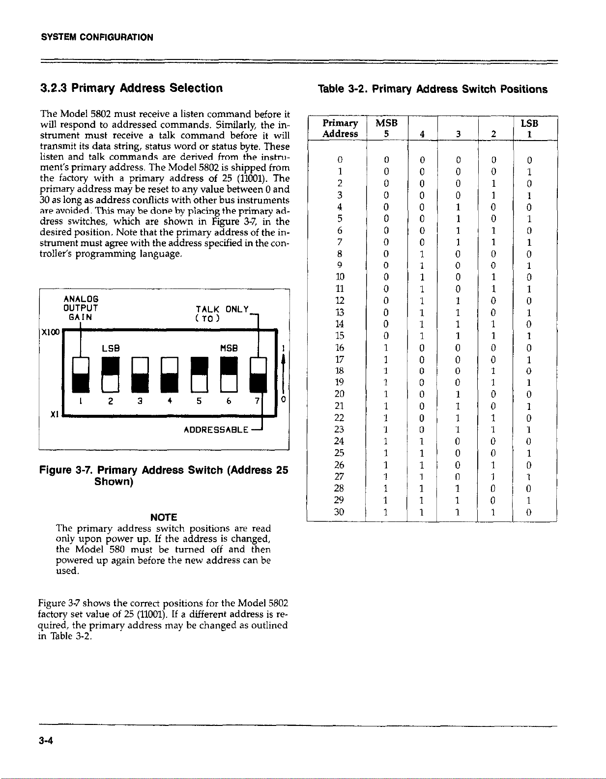
3.2.3 Primary Address Selection
The Model 5802 must receive a listen command before it
will respond to addressed commands. Similarly, the in-
strument must receive a talk command before it will
transmit its data string, status word or status byte. These
listen and talk commands are derived from the instrw
ment’s primary address. The Model 5802 is shipped from
the factory with a primary address of 25 (11001). The
primary address may be reset to any value between 0 and
30 as long as address conflicts with other bus instruments
are avoided. This may be done by placing the primary address switches, which are shown in Figure 3-7, in the
desired position. Note that the primary address of the instrument must agree with the address specified in the controller’s programming language.
ANALOG
OUTPUT
GAIN
TALK ONLY
(TO) 1
..-
LSG MB
h
mwdi
I 2 3 4 5 6 7 0
XI.
ADDRESSABLE -
Figure 3-7. Primary Address Switch (Address 25
Shown)
NOTE
The primary address switch positions are read
only upon power up. If the address is changed,
the Model 580 must be turned off and then
powered up again before the new address can be
used.
Table 3-2. Primary Address Switch Positions
Primary
Address
0 0
1
2 0
3
4 0
5 0
6 0
7
8
9
10
11
12
13 0
14
15 0
16 1
17 1
18 1
19 1
20 1
21 1
22
23 1
24
25 1
26
27
28
29
30
MSB
5
0
0
0
0
0
0
0
0
0
1
1
1
1
1
1
1
LSB
4
0
0
0
0
0
0
0
0
1
1
1
1
1
1
1
1
0
0
0
0
0
0
0
0
1
1
1
1
1
1
1
3
0
0
0
0
1
1
1
1
0
0
0
0
1
1
1
1
0
0
0
0
1
1
1
1
0
0
0
0
1
1
1
P-
__
2
0
0
1
1
0
0
1
1
0
0
1
1
0
0
1
1
0
0
1
1
0
0
1
1
0
0
1
1
0
0
1
1
0
1
0
1
0
1
0
1
0
1
0
1
0
1
0
1
0
1
0
1
0
1
0
1
0
1
0
1
0
1
0
Figure 3-7 shows the correct positions for the Model 5802
factory set value of 25 (11001). If a different address is required, the primary address may be changed as outlined
in Table 3-2.
3-4
Page 26

SYSTEM CONFIGURATION
NOTE
If other instrumentation is also connected to the
bus, be sure that each device has a different
primary address. If this precaution is not observed, erratic bus operation will result.
The primary address switches are binary weighted; Al is
the least significant bit, A5 is the most significant bit. For
example, the binary value for the factory set primary address of 25 is 11001. Use the tip of a pencil to operate the
switches.
NOTE Instruments should not be operated with a primary
address of 31 (11111) even though it is possible to set the
Model 5802 address to those positions. This address is
reserved for the UNT and UNL commands; erratic operation may result if primary address 31 is used.
3.3 SOFTWARE CONSIDERATIONS
The necessary handler routines to operate the IEEE-488
bus are described in this section.
3.3.1 Controller Interface Routines
Before a controller can be used with the IEEE-468 interface, make certain that appropriate handler software is present within the controller. The HP-85 interface card for the
HP-85 computer, for example, must be used with an additional 110 ROM, which contains the necessary handler
software.
Other small computers used as controllers have limited
IEEE-488 command capability. The PETKBM computers
are incapable of sending multiline commands from BASIC,
although these commands can be sent through machine
language routines. Other small computers’ capabilities depend on the particular interface being used. Often, little
software “tricks” are required to achieve desired results.
Make sure the proper software is being used with the interface. Often, the user may suspect that hardware is causing a problem when it is actually the software causing the
problem.
3.3.2 HP-85 BASIC Statements
Many of the programming instructions covered in Section
4 use examples written in Hewlett Packard Model 85
BASIC. The HP-85 was chosen for these examples because
it has a large number of BASIC statements that control
IEEE-488 operation. This selection covers those HP-85
BASIC statements essential to Model 58015802 operation.
A list of HP-85 BASIC statements is shown in Table 3-3.
All statements have a one or three digit argument that must
be specified. The first digit is the HP-85 interface select
code which is set to 7 at the factory. The last two digits
of those statements that require a three digit argument
specify primary address. Generally, only those commands
that require an address to be sent over the bus require that
the primary address be specified in the BASIC statement.
3-5
Page 27

SYSTEM CONFlGURATlON
Table 3-3. HP-85 IEEE-488 BASIC Statement
statement
ABORT10 7
CLEAR 7 Send DCL.
CLEAR 725 Send SDC to device 25.
ENTER 725;A$
LOCAL 725
OUTPUT 725;A5 Device 25 addressed to listen.
REMOTE 7 Set REN true.
REMOTE 725
RESET 7
SPOLL(725) Address device 25 to talk.
TRIGGER 7
TRIGGER 725 Address device 25 to listen.
Those statements in the table with three digit arguments
assume that the primary address of the device is set at 25.
Other primary addresses require that the last two digits
be set to the corresponding value. For example, to send
a GTL command to device 25, the following BASIC statement would be used.
Action
I
Send IFC.
Device 25 addressed to talk.
Data placed in A!$.
Send GTL to device 25.
Transmit A$.
Send REN true. Address device 25 to listen
Send IFC, cancel REN.
Conduct serial poll.
Send GET
Send GET.
BUS Command Sequence
F
IFC
ATN-DCL
ATN*UNL;MTA;LAG;SDC
ATN*UNL;MLA;TAG;ATN;data
ATN*UNL;MTA;LAG;GTL
ATN*MTA;UNL;LAG;ATN;data
REN
REN;ATNsL;MTA;LAG
1FC;REN;REN
ATN*UNL;MLA;TAG;SPE;ATN;
status byte;ATN*SPD;UNT
ATN*GET
ATN*UNL;MTA;LAG;GET
dresses sent by the HP-85 to facilitate bus operation in cer-
tain circumstances.
NOTE
The HP-85 address is set to 21 at the factory. Since
each device on the bus must have a unique
primary address, do not set the Model 5802 to the
controller’s address.
-
-
-
Some of the statements in the table have two forms; the
exact configuration used depends on the desired command. For example, CLEAR 7 will cause a DCL to be sent
to all devices on the bus, while CLEAR 725 causes an SDC
to be transmitted to device 25.
The third column of Table 3-3 lists command sequence
mnemonics. While most of these are covered elsewhere,
a couple of points should be noted. The ATN line is set
low by the controller if the data bus contains a multiline
command. This is indicated in the table by ANDing the
ATN mnemonic with the first command on the bus. For
example, ATN GET means that ATN and GET are sent
simultaneously. Two commands not previously covered are
MTA (My Talk Address) and MLA (My Listen Address).
These are ordinary PCG (Primary Command Group) ad-
3-6
3.3.3 Interface Function Codes
The interface function codes are part of the IEEE-488-1978
standards. These codes define an instrument’s ability to
support various functions and should not be confused
with programming commands found elsewhere in this
manual.
Table 3-4. lists the codes for the Model 5802. These codes
are also listed for convenience on the rear panel of the instrument immediately above the IEEE-488 connector. The
numeric value following each one or two letter code
defines Model 5802 capabilities as follows:
Page 28

SYSTEM CONFIGURATION
Table 3-4. Interface Function Codes
T
Code
SHl
AH1
l-5
L4
SRl
RLO
IT0
DC1
lm
co
El
TEO
LEO
SH (Source Handshake Function)-The ability of the
Model 5802 to initiate message/data transfer on the data
bus is provided by SH function.
AH (Acceptor Handshake Function)-Guaranteed proper
reception of message data on the data bus is provided by
the AH function.
T (Talker Function)-The ability of the Model 5802 to send
device-dependent data over the bus (to other devices) is
provided by the T function. Model 5802 talker capability
exists after the instrument has been addressed to talk.
L (Listener Function)-The ability of the Model 5802 to
receive device-dependent data over the bus (from other
devices) is provided by the L function. Listener function
capability of the Model 5802 exists only after the instrument has been addressed to listen.
SR (Service Request Function)-The ability of the Model
5802 to request service from the controller is provided by
the SR function.
RL (Remote Local Function)-The ability of the Model 5802
to be placed in the remote or local modes is provided by
the RL function.
PP (Parallel Poll Function)-The Model 5802 does not have
parallel polling capabilities.
DC (Device Clear Function)-The ability of the Model 5802
to be cleared (initialized) is provided by the DC function.
Interface Function
Source Handshake Capability
Acceptor Handshake Capability
Talker (Basic Talker, Serial Poll, Talk Only
Mode, Unaddressed To Talk On LAG)
Listener (Basic Listener, Unaddressed To
Listen On TAG)
Service Request Capability
No Capability
No Parallel Poll Capability
Device Clear Capability
Device Trigger Capability
No Controller Capability
Open Collector Bus Driver
No Extended Talker Capability
No Extended Listener Capability
DT (Device Trigger Function)-The ability for the Model
5802 to have its basic operation started is provided by the
DT function.
C (Controller Fun&m-The Model 5802 does not have
controller capabilities.
TE (Extended Talker Capability)-The Model 5802 does not
have extended talker capability.
LE (Extended Listener Capability)-The Model 5802 does
not have extended listener capability.
3.3.4 Interface Commands
Interface commands controlling Model 58015802 operation
are listed in Table 3-5. Not included in the table are devicedependent commands, which are covered in detail in Section 4.
Table 3-5. IEEE-488 Command Groups
HANDSHAKE COMMAND GROUP
DAC=DATA ACCEFTED
RFD=READY FOR DATA
DAV= DATA VALID
UNIVERSAL COMMAND GROUP
ATN=ATTENTION
DCL=DEVICE CLEAR
IFC=INTERFACE CLEAR
LLO=LOCAL LOCKOUT
REN=REMOTE ENABLE
SPD=SERIAL POLL DISABLE
SI’E=SERIAL POLL ENABLE
ADDRESS COMMAND GROUP
LISTEN: LAG=LISTEN ADDRESS GROUP
MLA=MY LISTEN ADDRESS
UNL=UNLISTEN
TALK: TAG=TALK ADDRESS GROUP
MTA=MY TALK ADDRESS
UNT=UNTALK
OTA=OTHER TALK ADDRESS
ADDRESSED COMMAND GROUP
ACG=ADDRESSED COMMAND GROUP
GET=GROUl’ EXECUTE TRIGGER
GTL=GO TO LOCAL
SDC=SELECTIVE DEVICE CLEAR
STATUS COMMAND GROUP
RQS=REQUEST SERVICE
SRQ=SERIAL POLL REQUEST
STB=STATUS BYTE
EOI=END
3-713-0
Page 29

SECT
ON 4
OPER
4.1 INTRODUCTION
The Model 5802 is an IEEE-488 interface for the Model 580
Micro-ohmmeter. Since all IEEE-488 operation is done
through commands given over the bus, IEEE-488 operation precludes the use of operating controls in the usual
sense. Instead, all operating functions are controlled by
programming.
This section describes important programming functions
in detail Included are: general bus commands, devicedependent commands, status word and status byte, and
other important information. The information presented
in this manual assumes that the operator is familiar with
all normal aspects of Model 580 operation. For information on front panel operation, refer to the Model 580
Operator’s Manual.
NOTE
mming examples in this section assume that
rrogra
the Model 5802 primary address is set to 25. Those
examples with &dressed commands will not function unless the primary address of the instrument
is set to that value. Refer to Section 3 for information on setting the primary address.
4.2 GENERAL BUS COMMANDS
General bus commands are those commands which have
the same general meaning regardless of instrument configuration. These commands are grouped into two
categories:
lTlON
General bus commands are summarized in Table 4-1,
which also lists the HP-85 BASIC statement that sends each
command. Each addressed command statement assumes
a primary address of 25 (11001).
Table 4-1. General Bus Commands
-
L-
*GET may be sent with or without addressing
4.2.1 REN (Remote Enable)
The remote enable command is sent to the Model 5802 by
the controller to set the instrument up for remote operation. Generally, this should be done before attempting to
program the instrument over the bus. The Model 58015802
indicates that it is in the remote mode by turning on the
front panel RMT annunciator.
To place the Model 58015802 in the remote mode, the con-
troller must perform the following steps:
Addressed Commands-These commands require that the
primary address of the instrument agrees with the primary
address in the controller’s language.
Unaddressed Commands-No primary address is required
for these commands. All devices equipped to implement
these commands will do so simultaneously when the command is sent.
1. Set the REN line true.
2. Address the Model 58015802 to listen
4-1
Page 30

OPERATION
NOTE
Setting the REN true without addressing will not
cause the REMOTE indicator to turn on: however.
once the REN is true, the REMOTE indicator turns
on the next time an addressed command is re-
ceived.
P&ramming Example-This sequence is automatically
sent by the HP-85 when the following is typed into the
keyboard.
After the END LINE key is pressed, the Model 580
REMOTE annunciator (RMT) should hnn on. If not, check
to see that the instrument is set for the proper primary
address. Also check to see that all the bus connections are
tight.
4.2.2 IFC (Interface Clear)
The IFC command is sent by the controller to set the Model
58015802 to the talk and listen idle states.
1. Set ATN true.
2. Address the Model 580/5802 to listen.
3. Place the GTL command on the bus.
Programming Example-If the instrument is not in the
remote mode, enter the following statements into the
HP-85 computer:
Check to see that the RMT annunciator is on. The GTL
command sequence is automatically sent by the HP-85
with the following statement:
Note that the remote (RMT) annunciator on the front panel
turns off.
NOTE
Setting the REN line false with the LOCAL 7 statement will also take the instrument out of the
remote mode
To send the IFC command, the controller need only set
the IFC line true.
Programming Example-Before demonstrating the IFC
command, turn on the front panel remote @MT) annunciator by entering the following statement into the HP-85
computer:
The front panel remote (RMT) annunciator should now
be on. The IFC command can now be sent by typing in
the following statement:
After the END LINE key is pressed, the Model 58015802
is in the talk idle state. Note that the remote mode is not
cancelled.
4.2.3 GTL (Go To Local)
4.2.4 LLO (Local Lockout)
The LLO command may be used to “lock out” front panel
button control on the Model 580. Note that all devices on
the bus equipped to respond to a LLO command will do
so simultaneously. When the Model 58015802 receives a
LLO command, the instrument will no longer respond to
front panel buttons, but can still be controlled over the bus
by the controller.
Programming Example-To put the instrument into local
lockout, enter the following statement into the HP-85
controller:
Note that the RMT and LLO annunciators come on
To get out of local lockout and remote, type:
The GTL command is used to take the instrument out of
the remote mode. To send the GTL command, the controller must perform the following sequence:
4-2
Both annunciators turn off
Page 31

OPERATION
To stay in local lockout but get out of remote (go to
LOCAL), type:
Note that the RMT annunciator turns off, but LLO stays
on.
4.2.5 DCL (Device Clear)
The DCL command may be used to clear the Model 580,
setting it to a known state. Note that all devices on the bus
equipped to respond to a DCL will do so simultaneouslv.
When the Model 58015802 receives a DCL command, it will
return to the default conditions listed in Table 4-2.
To send a DCL command, the controller must perform the
following steps:
1. Set ATN true.
2. Place the DCL command on the bus.
Programming Example-Using the front panel controls,
select POLARITY and the 2012 range. Type in the following statement into the HP-85 computer:
Programming Example-Using front panel controls select
DC drive. Enter the following statements into the HP-85
computer:
Note that the instrument did not respond to the SDC
because the command was sent with a primary address
of five. Now enter the following statement into the HP-85:
This time, the instrument returns to the default conditions
listed in Table 4-2 (pulsed drive).
4.2.7 Serial Polling (SPE, SPD)
The serial polling sequence is used to obtain the Model
58015802 status byte. Usually, the serial polling sequence
is used to determine which of several devices has requested
service over the SRQ line. However, the serial polling sequence may be used at any time to obtain the status byte
from the Model 58015802. For more information on status
byte format, refer to Paragraph 4.3.11.
The serial polling sequence is conducted as follows:
When the END LINE key is pressed after the CLEAR 7
statement, the instrument returns to the default conditions
listed in Table 4-2 (the POLARITY will return to its positive
power up condition).
4.2.6 SDC (Selective Device Clear)
The SDC command performs the same function as the
DCL command except that only the addressed device
responds. This command is useful for clearing only a
selected instrument instead of all instruments at once. The
Model 580 returns to the default conditions listed in Table
4-2 when responding to a DCL command.
To transmit the SDC command, the controller must perform the following steps:
1. Set ATN true.
2. Address the Model 5802 to listen.
3. Place the SDC command on the bus.
1.
The controller sets the ATN line true.
2,
The SPE (Serial Poll Enable) command is placed on the
bus by the controller.
3.
The Model 58015802 is addressed to talk.
4.
The controller sets ATN false.
5.
The instrument then places its status byte on the bus
to be read by the controller.
6.
The controkr sets the ATN line true and places the SPD
(Serial Poll Disable) on the bus to end the serial polling
sequence.
Steps 3 through 5 may be repeated for other instruments
on the bus by using the correct talk address for each instrument. ATN must be true when the talk address is
transmitted and false when the status byte is read.
Programming Example-The HP-85 SPOLL statement
automatically performs the serial polling sequence. Tu
demonstrate serial polling, momentarily power down the
instrument and power it up again. Enter the follo\~ing
statement into the HP-85 computer:
4-3
Page 32

OPERATION
When the END LINE key is pressed after the S=SPOLL
statement, the computer performs the serial polling sequence. When the END LINE key is pressed after the
DISP S statement, the status byte value (0) is displayed
on the CRT. The status byte has a value of 0 with this example because no bits in the byte are set. Paragraph 4.3.11
covers the status byte format in detail.
Table 4-2. Default Values (Status Upon Power Up
or After SDC or DCL)
Mode
Range
Operate
Dry Circuit Test
Relative
Calibration
Polarity
Drive
Trigger
EOI
SRQ
Alternate Output Prefix
Terminator
Value status
-
-
-
zo
-
PO Positive
DO
To
KO
MO No SRQ
GO Send Prefix
Y(CR)(LF) Carriage Return, Line
Reflects front panel
selection
Reflects front panel
selection
Reflects front panel
selection
Off
Off
Pulsed current
Continuous on TALK
EOI is transmitted on
the last byte out
Standard output
Feed
1. Ignore the entire command string.
2. Set appropriate error bits in the status byte.
3. Generate an SRQ if programmed to do so.
These programming aspects are covered in paragraph
4.3.11. HP-85 examples are included throughout this section to clarify programming.
NOTE
Before starting a programming example, it is
recommended that the instrument be set to its
default values by sending a DCL over the bus. See
paragraph 4.2.5 for information on using the SDC
command.
If the HP-65 should become “hung up” at any point (due
to inadvertent command errors, etc.), operation may be
restored by holding down the SHIFT key and then pressing RESET on the keyboard.
In order to send a device-dependent command, the controller must perform the following sequence:
1. Set ATN true.
2. Set the REN line true.
3. Address the Model 58015802 to listen.
4. Set ATN false.
5. Send the command string over the bus one byte at a
time.
4.3 DEVICE-DEPENDENT COMMAND
IEEE-488 device-dependent commands are sent to the
Model 58015802 to control its various operating modes.
Each command is made up of an ASCII alpha character
followed by one or more numbers designating specific
parameters. For example, REL is programmed by sending
an ASCII “Z” followed by a zero or one for turning it off
or on. The IEEE-488 bus treats device-dependent commands as data in that ATN is high when the commands
are transmitted.
A number of commands may be grouped together in one
string. A command string is terminated by an ASCII “X”
which tells the instrument to execute the command string.
If an illegal command or command parameter is present
within a command string the instrument will:
Programming Example-Device-dependent commands are
sent by the HP-85 using the following statement:
A$ in this case contains the ASCII characters that form the
command string.
NOTE
REN must be true when attempting to program
the Model 580. If REN is false, the RMT annunciator will be off.
Commands that affect the Model 580 are listed in Table
4-3. All the commands listed in Table 4-3 are covered in
detail in the following paragraphs.
NOTE
The programming examples that follow assume
that the Model 58015802 primary address is at its
factory setting of 25 (11001).
4-4
Page 33

Table 4-3. Device-Dependent Command Summary
OPERATION
Store Calibration Constants
Polarity
Jn,
EOI
SRQ
Command
f
V
1
X
RO
Rl
R2
R3
iTi
R6
R7
::
co
Cl
zo
Zl
tn.nnnnE+nn
Ix
PO
PI
DO
Dl
To
Tl
T2
I3
E
:
M”“”
Bits:
MSB 7
6
5
4
3
2
LSB 0’
UO
GO
Gl
Y(ASCII)
VW
WN
Y(DEL)
hcription
mplement all DDCs when an X is received.
hn Dry Circuit Test
iuto
!OOm
2
20
!OO
2k
20 k
!OO k
standby
3perate
\Jon Dry Circuit Test
3ry Circuit Test
XEL off
?.EL on
Enter calibration. Calibration point equal to the input
:esistance.
Store calibration constants and exit calibration.
P01+
PolPulsed Drive
DC Drive
Continuous on Talk
One-shot on Talk
Continuous on GET
One-shot on GET
Continuous on “X”
One-shot on “X”
EOI is transmitted on the last byte out.
EOI is not transmitted.
nnn = 0 to 255 base 10
N/A = Bit ignored
Data
N/A
SRQ
NORMAL=0
BUSY
READING DONE
N/A
N/A
READING OVERFLOW
Output the status word on the next reading.
Send prefix.
Do not send prefix.
ASCII character
(CWLF)
(WKW
No terminator
I
Dry Circuit Test
Auto
200m
2
20
20
20
20
20
ElTlJr
N/A
SRQ
ERROR=1
N/A
N/A
NOT IN REMOTE
IDDC
IDDCO
1
,
I
4-5
Page 34

OPERATION
4.3.1 Execute (X)
The execute command is implemented by sending an
ASCII “X” over the bus. Its purpose is to tell the Model
580/5802 to execute the other device-dependent commands. Generally, the “X” character is the last byte in the
command string. Also, “X” triggers the instrument in T4
and T5.
NOTE
Command strings sent without an “X” character
will not be executed at that time. They will be
stored in the command buffer. The next time an
“X” character is received. the stored commands are
executed assuming all commands in the previous
string were valid.
Programming Example-From the front panel, make
polarity positive. Then, enter the following example into
the HP-85 computer:
K:EFlOTE 71’5
c,,JTP,JT 7)5,; i i plji:! 1
Table 4-4. Range Commands
Range
Command
Rl
R2
R3
R4
R5
R6
R7
Ron Dry Circuit Test
Descrip
RO
200m
2;
200
2k
20 k
200 k 20
Autc
tio
”
Dry Circuit Test
1
Auto
200m
20
20
20
20
I
-
2
4.3.3 Operate/Standby (0)
With the use of the 0 command, the Model 580 can be
put in either operate (ready to take readings) or standby
by the controlier.
00 = Standby
01 = operate
Polarity is now negative, which indicates that the instrument received the command.
Upon power up, or after a DCL or SDC command, the
status of the 0 command reflects the front panel button
selection.
4.3.2 Range (R)
Ranges are programmable over the bus. The range com-
mands can be found in Table 4-4. Upon power up, or after
receiving a DCL or SDC, the range of the Model 580 corresponds to the range pushbutton selected.
Programming Example-Cycle power on the Model 580
and manually select the 2Q range. Enter the following
statements into the HP-85:
Programming Example-Model 580 is put into standby
with the following HP-85 statement sequence:
F:EPll:lTE 725
,z 11-1 TF’,JT 725,; i i ,:,l;~:;! ?
The instrument is now in standby.
4.3.4 Dry Circuit Test (C)
,I il., TP,-,T 725; 6 6 F:~:z:> ?
The status of the Dry Circuit Test function of the Model
580 on power up refl&s the front panel button selection.
When the END LINE is pressed the second time, the in- If Dry Circuit Test is chosen with a range higher than 200,
strument switches to the R3 ranee (20R). “En” will atwear on the instrument disulav. and the ohms
and DRY &RCUIT TEST annunciators &I flash,
4-6
Page 35

OPERATION
CO = Non Dry Circuit Test
Cl = Dry Circuit Test
Programming Example-Model 580 is put into Dry Cir-
cuit Test with the following HP-85 statement sequence:
The instrument is now ready to take dry circuit test
measurements; the DRY CIRCUIT TEST annunciator appears on the Model 580 display.
4.3.5 Relative (2)
REL serves as a means for a baseline suppression. When
the correct REL command is sent over the bus, the instrument will enter REL, as shown by the REL annunciator.
All readings displayed or sent over the bus while REL is
enabled are the differences between the stored baseline
and the actual resistance level. For example, if a 1OOmQ
baseline is stored, 1OOmQ will be subtracted from all subsequent readings as long as REL is enabled. The value of
the stored baseline can be as little as a few micro-ohms
or as large as the selected range will permit. REL is controlled by sending one of the following commands over
the bus.
4.3.6 Digital Calibration (V) and Storage (L)
Calibration over the IEEE-488 bus can only be accomp-
lished with the calibration switch in the ENABLED posi-
tion. Refer to the Model 580 Service Manual for complete
information.
Through the use of the V command, the Model 580 enters
calibration and the calibration value is transmitted to the
instrument. The calibration command is in the form:
V+n.nnnnE+nn
where: +n.nnnn represents the mantissa (4% digits)
E+nn represents the exponent
Through the use of the LO command the calibration values
entered are stored in NVRAM, then the Model 580 is
returned to normal operation.
NOTES:
1. Only as many significant digits as necessary need to be
entered. For example, for calibration of the 203 range
with a 19.0000 input value, the following command
would be used:
ZO = REL Disabled
Zl = REL Enabled
Upon power-up, or after DCL or SDC, ZO is selected.
Programming Example-With the front panel REL button,
disable REL and enter the following statements into the
HP-85 keyboard:
After the END LINE key is pressed the second time, the
REL annunciator will turn on.
NOTE
See the Model 580 Instruction Manual for detailed
information on the use of REL.
2. The correct calibration value must be connected to the
instrument before the V command is sent.
Programming Example-
CAUTION
If the calibration switch is in the ENABLED posi-
tion (refer to the maintenance section of the
Model 580 Service Manual), DO NOT PERFORM
THESE STEPS UNLESS A CHANGE IN CALI-
BRATION IS DESIRED. Unless proper calibration parameters have been previously programmed, inadvertently using this command
seriously affects instrument accuracy.
Using front panel controls, place the instrument in the 2P
range. Connect a precise 1.9Q calibration resistor to the
Model 580 test leads and enter the foliow,ing statements
into the HP-85 computer:
4-7
Page 36

OPERATION
When the END LINE key is pressed after the Vl.9X statement, the instrument calibrates itself in accordance with
the applied signal.
When the END LINE key is pressed after the LOX statement, permanent storage takes place.
4.3.7 Polarity (P)
The Model 580 provides a selectable positive or negative
SOURCE current. The red SOURCE terminal is positive
for PO and negative for l’l.
PO=Positive
l’l=Negative
Upon power up, or after a DCL or SDC command, the
PO (positive) is enabled.
After END LINE is pressed the second time, the instru-
ment will be placed in DC ( -=).
4.3.9 Triggering (T)
Triggering provides a stimulus to begin a reading conver-
sion within the instrument. Triggering may be done in two
ways: in continuous, a single trigger command is used to
start a continuous series of readings; in one-shot, a
separate trigger stimulus is required to start each conver-
sion. The Model 580 has six trigger commands as follows:
To Continuous On Talk
Tl One-Shot On Talk
T2 Continuous On GET
T3 One-Shot On GET
T4 Continuous On X
T5 One-Shot On X
Upon power-up or after a DCL or SDC command, To is
enabled. In ‘ItI and Tl, triggering is done by addressing
the Model 580 to talk. In TZ and T3, a GET command provides the trigger stimulus. In T4 and T5, the execute (X)
character triggers the instrument.
Programming Example-Enter the following commands
into the HP-85 follows:
The SOURCE current is now negative.
4.3.8 Drive (D)
The DRIVE feature of the Model 580 allows the user to
measure an unknown with a DC or pulsed source.
DO = Pulsed drive
Dl = DC drive
Upon power up, or after the instrument receives a DCL
or SDC command, the DO or pulsed source is enabled.
Programming Example-DRIVE can be entered or changed with the following HP-85 statement sequence:
FEp,l:lTE -‘?y
,L,,jTP,JT 725,; i i 1,ii.g ?
I..
Programming Example--Place the instrument in one-shot
talk with the following HP-85 statement sequence:
After the END LINE key is pressed the second time, the
instrument will be in one-shot on talk. The instrument is
waiting for a trigger.
Trigger the instrument with a talk command by entering
the following statement into the HP-85
After pressing END LINE one reading will be processed.
To continue taking readings, one talk command must be
sent for each conversion.
4.3.10 EOI (K)
The EOI line on the bus is usually set low by a device during the last byte of its data transfer sequence. The Last byte
4-8
Page 37

OPERATION
is properly identified, which allows variable length data
words to be transmitted. The Model 580 normally sends
EOI during the last byte of its data string or status word.
The EOI response of the instrument may be sent with one
of the following commands:
KO = Send EOI during last byte.
Kl = Send no EOI.
KO is assumed at power up,
Programming Example-Model 580 EOI response is sup
pressed with the following HP-85 statement sequence:
Note that the HP85 does not normally rely on EOI to mark
the last byte of data transfer. Some controllers, however,
may require that EOI be present at the end of the transmitted string.
4.3.11 SRQ (M) and Status Byte Format
The SRQ command code controls the number of conditions within the Model 580 which cause the instrument
to request service from the controller with the SRQ com-
mand. Once the SRQ is generated, the Model 580 status
byte can be checked to determine if it was the Model 580
that requested service. Other bits in the status cycle could
also be set depending on certain data or error conditions.
The Model 580 can be programmed to generate an SRQ
under one or more of the following conditions:
1. If a reading has been completed.
2. If an overflow condition occurs.
3. If a busy condition occurs.
4. If an Illegal Device-Dependent Command Option
(IDDCO) is received.
5. If an Illegal Device-Dependent Command (IDDC) is
received.
6. If the instrument is not in remote when a command is
received.
Upon power up or after a DCL or SDC command, SRQ
is disabled.
SRQ Mask-In order to facilitate SRQ programming, the
Model 580 uses an internal mask to generate an SRQ.
When a uarticular mask bit is set, the Model 580 sends
an SRQ Ghen those conditions occur. Bits within the mask
can be controlled by sending the ASCII letter “M” followed by a decimal number to set the appropriate bits. Table
4-5 lists the commands to set the various mask bits, while
Figure 4-l shows the general mask format.
Table 4-5. SRQ Mask Commands
Command Status Bits Enabled Conditions to Generate SRQ
MO - Clear SRQ Data Mask
Ml Readine Oveflow
MB ii Reading Done
M9 83, 80
Ml6 84
Ml7 84, BO
M24 84, 83
M25 84, 83, 80
M32 85
M33 85, BO
iti: 85, 85, 81 Bl, BO
M36 85, B2
M37
B5, 82, BO
M38 85, B2, 81
M39 85, B2, Bl, 80
Reading Done or Reading Overflow
Busy Busy or Reading Overflow
Busv or Reading Done
Busv. Rq sadine Done or Reading Overflow
Cle& SRQ EGor Mask
IDDCO
IDDC
IDDC or IDDCO
Not in Remote
Not in Remote or IDDCO
Not in Remote or IDDC
Not in Remote, IDDC or IDDCO
I
”
4-9
Page 38

Programming Example-Cycle power on the Model 580
and program it for SRQ on IDDCO and output the status
word.
PROGRAM COMMENTS
Table 4-6. Status Byte and Mask Interpretation
Bit 5 = 0 Bit 5 = 1
Bit (Data Conditions) (Error Conditions)
0 (LSB)
1
2
3 Reading done
4
5 Data
6
7
Busy
SRQ SRQ
N/A
N/A
ErPX
NJA
the computer.
Display on CRT.
After entering the program, press the HP-85 RUN key. The
UO status word wiIl then be displayed. The Me bytes (refer
to Figure 4-2) contain “01” indicating that the Model 580
is prwrammed to SRO on an IDDCO.
. ”
Status Byte Format-The status byte contains information
relating to data and error conditions within the instrument.
When a particular bit is set, certain conditions are present.
Table 4-6 lists the meanings of the various bits and Figure
4-l shows the general format of the status byte, which is
obtained by using the SPE, SPD polling sequence described in
paragraph 4.2.6.
o- ’
DATA BUSY DONE OVERFLOW
MSB 87 86 ES 84 93 B2 Bl
I- I- NOT
SRD ERROR
i
If the status byte is read when no SRQ was generated by
the Model 580 (bit 6 is clear). the current status of the in-
I.
strument will be read. For example, if a reading was done,
bit 3 would be set.
When an SRQ is generated by the Model 580, bit 6 of the
status byte will be set. If an SRQ was caused by an error
condition, bit 5 will also be set along with one of the error
conditions (BO, Bl or 82). Only the-error that caused the
initial SRQ will be defined by the status byte.
DATA CONDITIONS E-0
READING
READING
I
BO LSB
IDDC IDDCO
REETE
I
ERROR CONDITIONS 85-l
I
4-10
Figure 4-1. Status Byte Format
Page 39

O=STANDBY
I=OPERATE
DRY CIRCUIT TEST
O=NON DRY CIRCUIT TEST
I= DRY ClRCVlT TEST
O=POSITI”E
l=NEGATI”E
OPERATION
I
RANGE
n- nl,Tn
I- LVY,,II,
2= 2n
3=
4= 200
5= 2 k”
6= 20 IdI
7= 20Dk”
20
R
R
RELATIVE- 1 1 1 1 I
O=REL OFF
I=REL ON
EOI
O=EOI ENABLED
1=EDI DISA6LE I = 5a-k
TRIGGER-
O=CONTINUOUS ON TALK
l=ONE-SHOT ON TALK
2=CONTINUOUS ON GET
S=ONE-SHOT ON GET
4=CONTINUOUS ON “X”
6=ONE-SHOT ON “X”
SRO DATA MASK m
O,=READING OVERFLOW
08=READING DONE
OS=READING DONE OR READING OVERFLOW
16=BUSY
17=B”SY OR READING OVERFLOW
24=WSY OR READING DONE
26=B”SY. READING DONE OR READING OVERFLOW
'II I
L
-SRQ ERROR MASK
I
TERMINATOR
ASCII CHARACTER
iCRllLFl
iLFllCR1
ND TERMINATOR
0=60Hz
Ol=IDDCO
02=IDDC
Ol=lnn,-Cl OR ,,,,JC
-_ .II-”
O4=NOT IN
06=NOT IN
06=NOT IN REMOTE OR IDDC
07=NOT IN REMOTE, IDDCO OR IDDC
REMOTE
REMOTE OR IODCO
Figure 4-2. General Format for UO Command
4-H
Page 40

OPERATION
If the SRQ was caused by a data condition, bit 5 will be
clear and the appropriate data condition bits (BO, B3 and
B4) will be set. If a busy condition caused the SRQ then
only the busy bit will be set.
After an SRQ, the status byte will remain unchanged until it is read. The various bits in the status byte are described
below:
Reading Overflow-Set when an overrange input is applied to the instrument.
Reading Done-Set when the instrument has completed
the present conversion.
Busy-The instrument is still executing a prior command
and is not ready to accept a new command.
IDDCO-An illegal command option such as R9 has been
received from the controller. This bit is cleared when the
status byte is read.
IDDC-An illegal command, such as Nl, has been received from the controller. The IDDC bit is cleared on a
reading of the status byte.
Not in Remote-The Model 580 is in local when a DDC
is received.
PROGRAM COMMENTS
Set up for remote
operation.
Program for SRQ on
IDDCO.
Attempt to program illegal command option.
Perform serial poll.
Loop eight times
NOTE
To align the display properly, type in the program
exactly as shown. In line 100 the space between
the first quotation marks and the fist pointer is
four spaces. Then to the next pointer is two spaces,
and 14 spaces to the last pointer in the line. In line
110 the space between the first quotation marks
and SRQ is two spaces. Then to ERROR allow two
spaces and then 10 spaces to IDDCO.
NOTES:
1. Once the Model 580 has generated an SRQ, its status
byte must be read to clear the SRQ line. Otherwise the
instrument continuously asserts SRQ.
2. The Model 580 may be programmed to generate an SRQ
for more than one condition simultaneously.
Programming Example-Enter the following program into the HP-85 computer.
To run the program press the HP-85 RUN key. The computer conducts a serial poll and displays the status bits in
order on the CRT. The SRQ (B6), error (B5) and IDDCO
(Bl) are set because line 30 of the program attempted to
program the instrument with an illegal command option
(R9).
After the program has been entered, press the HP-85 RUN
key. Note the CRT, it will be as follows:
412
Page 41

OPERATION
B7 B6 85 B4 B3 B2 Bl BO
0 1100010
v
w.6 ZRROR
Bit 6 (86) is set, meaning a SRQ condition exists. Bit 5 (85)
is also set, meaning there is an error condition. Bit 1 is
set, meaning an Illegal Device-Dependent Command Option (IDDCO) condition exists.
IDDCO
4.3.12 Status Word (U) or Alternate Output
The status word commands allow access to information
concerning present operating modes of the instrument.
When the status word command is given, the Model 580
transmits status information instead of its normal data
string the next time it is addressed to talk. The Model 580
status word command is:
UO = Send instrument status on operating modes.
Figure 4-2 shows the general format for the UO command.
The letters in the UO format correspond to other device-
dependent commands.
PROGRAM
After entering the program, press the HP-85 RUN key. The
UO status word is then displayed on the CRT. Refer to
Figure 4-l.
COMMENTS
Set up instrument for
remote operation.
Send UO status
command.
Enter status word into
computer.
4.3.13 Prefix (G)
With the use of the G command, the prefi for the status
word or data string can be either transmitted or deleted.
The commands are as follows:
GO = Include prefix
Gl = Suppress prefix
NOTES:
1. Status word information is returned only once each time
the command is sent.
2.The returned terminator character (Y) is derived by
ANDing the 00001111 and ORing the result with
00110000. For example, the last byte in the normal (CR
LF) terminator sequence is an LF or ASCII 10 (oooO1010).
ANDing with 00001111 yields 00111010 which is printed
out as an ASCII colon (:).
3. The status word should not be confused with the status
byte. The status word contains a number of bytes pertaining to the various operating modes of the instrument. The status byte is a single byte that is read with
the SPE, SPD command sequence and contains information on SRQ status and error and data conditions.
4. The returned SRQ mode (M) value is determined by adding up the value of the bit positions in the status byte
that could cause an SRQ according to the previous programmed value of the SRQ mode. Refer to paragraph
4.3.11 for complete information on the SRQ mask and
status byte.
5. Line frequency (H) is 0 for 60Hz and 1 for 50Hz.
Programming Example-Enter the following program in-
to the HP-85. Be sure to include line numbers.
Upon power up or after a DCL or SDC command, the GO
mode is enabled.
Programming Example-Program the Model 580 to out-
put a data string without the prefix.
PROGRAM COMMENTS
163 F:EP,BTE 7’25
.:Ei ~IlJTPlJT 725; c 6 ,;li.::’ 3 Suppress p*&.
30 EHTER 7.25,; HS
40 IlI:;p I?($
50 E,.,I,
To run the program, press the HP-85 RUN key. The data
string appears on the CRT without the prefix (N+NP).
Refer to Figure 4-3, which shows the data string format
with the prefix.
Set up for remote
operation.
Enter command into the
computer.
Display data string on
CRT.
413
Page 42

Programming Example-The terminator can be eliminated
by sending an ASCII DEL with the following HP-85
statements:
N=NORMAL
O=OVERFLOW
Z=ZERO
:
EXPONENT
P=P”LSED
D=DRY CIRCUIT TEST
Figure 4-3. Data Format
4.3.14 Programmable Terminator (Y)
The Model 580 uses special terminator characters to mark
the end of its data string or status word. To allow a wide
variety of controllers to be used, the terminator can be
changed by sending the appropriate command over the
bus. The default value is the commonly used carriage
return, line feed (CR LF) sequence. The terminator sequence assumes this default value upon power up or after
the instrument receives a DCL or SDC.
The terminator may be programmed by sending the ASCII
character Y followed by the desired terminator character.
Any ASCII character except the following may be used:
When the END LINE key is pressed the second time, the
terminator is suppressed; no terminator is sent by the instrument when data is requested. The absence of the normal terminator may be verified by entering the following
statement into the HP-85 computer:
At this point the HP-85 ceases to operate because it is
waiting for the standard CR LF terminator sequence to terminate the ENTER statement. The computer may be reset
by holding down the SHIFT key and pressing the RESET
key on the keyboard. To return the instrument to the normal terminal sequence, enter the following statement into
the HP-85 computer:
4.3.15 Data Format
Model 580 data is transmitted over the IEEE-488 bus as a
string of ASCII characters with the format shown in Figure
4-3.
1. Any capital letter.
2. Any number.
3. Blank
4. + - i ore
Special command characters will program the instrument
for special terminator sequence as follows:
1. Y(LF) = CR LF (Two terminators)
2. Y(CR) = LF CR (Two terminators)
3. Y(DEL) = No terminator
NOTE
Most controllers use the CR or LF character to terminate their input sequence. Using a nonstandard
terminator may cause the controller to hang up
unless special programming is used.
4-14
The first four characters indicate the function status of the
Model 580. The first character shows if the unit is in standby (S), normal (N), overflow (0) or zero (2); the second
character indicates positive polarity (+) or negative polarity
(-); the third character indicates if the unit is in Dry Circuit Test (D) or in non-Dry Circuit Test (N); and the fourth
character indicates pulsed drive (I’) or DC drive (D).
The mantissa of the reading is made up of eight characters,
including sign and decimal point, while the exponent requires three characters. To obtain the data string from the
instrument, the controller must perform the following
sequence:
1. Set the ATN true (low).
2. Address the instrument to talk.
3. Set ATN false (high).
4. Input the data string one byte at a time.
Page 43

OPERATION
NOTE
The data string can be transmitted without the
prefix 580.
programming Example-Cycle power on the Model 580
(turn it off, then on) and program it to output a data string.
PROGRAM
18 REllOTE 725
50 ENTER 725; A$ Enter data string into controller.
30 1,1:jp (48
40 EM
To run the program press the HP-85 RUN key.
COMMENTS
Set up for remote operation.
Display data string on CRT.
4.4 TALK ONLY OPERATION
The talk only feature of the Model 58015802 may be used
to send data to a listen only device such as printer. When
the Model 580 is in talk only, it ignores commands given
over the IEEE-488 bus. Talk only is enabled by placing the
TWADDRESSABLE switch of the primary address switch
in the ‘I0 position (refer to Figure 3-7) and cycling power
to the instrument. The talk rate is typically three readings
per second, depending on the function. However, a different talk rate can be selected using an external trigger
source by performing the following procedure:
1. Enable the listen only capability of the receiving device
(such as a printer).
2. Connect the Model 580/5802 to the listen only device
with an appropriate IEEE-488 cable.
3. Place the LSB (least significant bit) switch on the Model
5802 at 0 to send a prefix with the reading, or at 1 to
send data only (suppress the prefix).
4. Power up Model 580 (again, default reading rate is three
readings per second).
5. Press SHIFT, then SINGLE to put the instrument in oneshot. Now, every time SINGLE is pressed or an external trigger is received, a reading will be taken (up to the
maximum reading rate of that function).
When the Model 580 is used in talk only, it may be interfaced with one or more listeners. Each of these devices and
associated cables should conform to IEEE-488-1978
standards.
The Model 580 transmits its normal data string in bit
parallel byte serial fashion over the bus as requested by
the listeners. The data format used is the same one used
for addressable operation and is described in detail in
paragraph 4.325. If the address switches are set to an odd
number the prefii is sent with the reading. An even address number sends only the data.
4-15/4-16
Page 44

5.1 INTRODUCTION
SECTION 5
ANALOG OUTPUT
The analog output is an important feature of the Model
5802 IEEE-488 Interface. It is useful for monitoring the input signal with an exkrnal device such as a chart recorder.
The analog signal is reconstructed from digital data (supplied by the internal microprocessor) by a 13 bit D/A converter. Because of this condition the analog output accurately reflects the display until an overflow condition is
reached. The analog output is optically isolated from the
Model 580 to avoid potential ground loop pmblems. There
are two levels of gain for the analog output, the Xl gain
and the Xl00 gain. Refer to paragraph 5.4.
On the Xl gain, 1V at the analog output corresponds to
10,000 counts on the Model 580 display. On the Xl00 gain,
1V at the analog output corresponds to 100 counts on the
Model 580 display.
The accuracy of the analog output is *0.25% of displayed
reading +2mV, where 2mV in Xl00 = 0.2 displayed counts.
Update of analog output is coincident with update of the
display.
5.2 USING THE ANALOG OUTPUT
The analog output is useful for monitoring the input signal
with an external device such as a chart recorder. Using the
analog output connected to chart recorder produces a
hardcopy of the input signal over a period of time.
r I
I? lo
mmu?
REAR PANEL
Figure 5-1. Analog Output Connections
CAUTION
The potential between the analog output LO ter-
minal and earth ground must not exceed 30V
RMS at DC, 50 or 60Hz peak. Make sure the ex-
ternal device does not exceed this voltage on
its common or ground connections. Failure to
observe this precaution may damage the Model
58015802. IEEE-488 common is connected to
analog output common.
WARNING
The potential between the SOURCE LO of the
Model 580 and the analog output LO of the
Model 5802 must not exceed 30V RMS et DC,
50 or 60Hz. Failure to observe this precaution
may result in a dangerous potential being present on the analog output terminals and the
IEEE-488 connector. This situation could result
in personal injury or death.
1. Connect the measuring device to the two analog output terminals on the rear panel as shown in Figure 5-l.
5-l
Page 45

ANALOG OUTPUT
2. Select the desired gain. The gain switch is located on
the rear panel. A logic one (up position) is the Xl00 gain.
A logic zero (down position) is the Xl gain.
Xl gain--Set switch to logic 0.
Xl00 gain-Set switch to logic 1
In the Xl position, the most significant k2000 counts
of the displayed reading can be covered. The span on
this range (Xl) is t2V in 1mV steps. In the Xl00 position, the least significant 400 counts of the displayed
reading can be covered. The span on this range is t4V
in 1mV steps.
3. If necessary, the analog output may be zeroed with the
REL function. To do so, press the REL button on the
front panel. All subsequent readings are referenced to
the previously displayed value. Refer to the Model 580
Operator’s Manual for complete details concerning the
REL function.
The Model 580 displays an “OL” message when the
capability of a specific range is exceeded. When this
message is displayed and the Xl gain is selected, the analog
output value is +2V if the polarity of the displayed value
is positive and -2V if the display value is negative. The
analog output value is +4V respectively if the Xl00 gain
is selected.
An analog output range overflow can occur when the
Model 580 analog range switch is in the Xl position. An
example of the analog output voltage under these conditions is shown in Figure 5-2. The conditions shown are
for the Model 580 in the 2COmR range, but the output reacts
similarly on the other resistance ranges if the proper scaling is applied. For each tenfold increase in range, the scale
of the horizontal axis must also be multiplied by a factor
of ten.
The horizontal axis of Figure 5-2 has a range of -199.99mR
to +199.99mR.
The analog output follows the display value linearly until
the input resistance reaches 19999 counts (either positive
or negative). The analog output then outputs the range
overflow voltage of +2V depending on the polarity of the
display value.
A summary of analog output information is shown in Table
5-l. Each range of input values corresponds to the increment necessary to cause the analog output to go through
its entire 0 to i2V range.
5-2
---2”
‘-OL’ DISPLAYED
Figure 5-2. Xl Analog Output
t
-3v
t
ANkOS
OUTPUT
Page 46

ANALOG OUTPUT
Table 5-1. Analog Output Parameters
Range
Input for 1.99v
Analog Output
Input for 4.oov
Analog Output
X1
2OOmR
2 0
20 0
200 0
2 kR
20 kn
200 kR
199mR
1.99n
19.9R
19961
1.99kR
19.9kQ
199kR
Xl00
4.00mn
40.0mQ
400mR
4.00R
4o.ofl
4000
4.OOkR
5.3 OUTPUT RESISTANCE
The output resistance of the analog output is lkSL This
is true for all ranges regardless of the gain status. Thus,
loading problems caused by external devices are minimized. In order to keep loading errors below l%, the in-
put resistance of any device connected to the analog out-
put should be greater than 100kO.
5.4 Xl00 RESOLUTION AND ACCURACY
In Xl00 the analog output increases the resolution of the
Model 580 beyond the 4% digits of the display. This provides an output step size of 2mV per each 0.2 counts of
the displayed reading. For example, on the 200mR range,
a 2mV step in the analog output voltage corresponds to
a 2~12 change in applied resistance to the Model 580. The
extra resolution allows for a more continuous output.
ANALOG
OUTPUT
Figure 5-3. Xl00 Analog Output
5-315-4
Page 47

SECTION 6
PRINCIPLES OF OPERATION
6.1 INTRODUCTION
This section contains a circuit description of the Model 5802
interface. The IEEE-488 interface option enables the Model
580 to be incorporated into a measurement system that
utilizes programmed control through the IEEE-488 bus.
6.2 CIRCUIT DESCRIPTION
The entire IEEE-488 interface circuitry is located on a single
board. The schematic number for the Model 5802 is
5802-106. Figure 6-l shows a simplified block diagram of
the interface. The following descriptions cover the power
supply, digital circuitry and analog output circuitry.
-
-
ODEL
980
OPT0 PROCESSOR GUS
ISOLATION CONTROLLER
UlO7 Ulli! Ul15
Ull3
6.2.1 Power Supply
The positive supply (V+) provides power to the +5V
regulator VR104, LJ109 and U110. The supply voltage to
U109, UllO and VR104 must be a minimum of +7.OV for
V+ and -6.2V for V- to allow ample supply head room
in order for the outputs to swing to their specified voltages.
The negative supply V- is generated using Cll2, CR102,
CR103 and Cl08 configured as a voltage inverter. During
the positive going cycle of the line, CR102 is forward biased
allowing Cl12 to charge to the peak voltage of the AC IN.
CR103 is reversed biased. On the negative going line cycle
CR102 is reversed biased and CR103 is forward biased
allowing the charge on Cl12 to be transferred onto C108.
Thus Cl08 is charged to -VP (negative peak voltage).
DATA BUS
TRANSCEIVER
Ull4
ANALOG OUTPUT
UIOI AND U109
L
Figure 6-1. Simplified Block Diagram
ii-l
Page 48

PRINCIPLES OF OPERATION
6.2.2 Digital Circuitry
The digital circuitry consists of the microprocessor (UlOZ),
EPROM (U104), decoder (Ulll), IEEE-488 controller (Ull2)
and bus transceivers (U114 and Ull5). Reset for the interface is accomplished by the internal reset feature of the
microprocessor (U102) and its Ii0 line (PBl). Upon power
up the microprocessor executes an internal reset routine.
This cycle lasts 1920 clock cycles (one cycle = 8OOkHz =
125~sec). After configuring itself, the processor sets PBl
low then high. This resets the IEEE-468 controller (Ull2).
Figure 6-2 shows the memory map for the interface,
SIFFF
SlFF6
SIFF5’
Slwo
SCFFF
INTERRUPT
VECTOR JAM
READ ONLY
MEnORY
NOT USED
NOTE
The primary address is updated only upon power
“P.
The address switch is read through Port A (PA2-PA6) of
u102.
6.2.3 Analog Output
The analog output of the Model 5802 is derived from the
displayed reading of the Model 580. This reading is sent
over the opto interface to the Model 5802. The digital
reading is then transformed to an analog output by a l3
bit DAC (digital-to-analog converter) on the Model 5802.
The DAC is composed of a 12 bit serial input monolithic
CMOS multiplying DAC and a *4V polarity switchable
reference. The output of the DAC is given by:
12 bit word
v.., =--VW
4096
m6oo
SO?FF
:i?iz
so080
IcmF
mooo
IEEE-M
BUS
NOT USED
I/O PORTS
TIMER Uloz
RMl
Figure 6-2. Memory Map
The interface is capable of performing all IEEE-488
talker/listener protocols. The bidirectional data lines DO
through D7 permit the transfer of data between the
microprocessor and the bus. The transceivers are used to
drive the output and also buffer the data.
The primary address switches (SWlOl) select the primary
address and permit 31 primary talker/listener address
pairs. To address the Model 580, the controller must lend
the primary address of the Model 580. The factory set address is 25 (11001). The microprocessor reads the primary
address from SWIOl and then knows which talker/listener
address to assign the IEEE-466 controller and thus the
Model 580.
Data is sent to the serial input DAC over three control lines
(Data, Clock and Strobe). The DATA is clocked into the
DAC on the rising edge of the clock. Once all 12 bits have
been sent, pulling the strobe line low forces the output
of the 12 bit DAC to a level corresponding to the new DAC
input. The polarity of the 4V reference is controlled by the
processor through UlOl, QlOl and 4102. For a positive
reference voltage, the sign bit is low, allowing +5V to be
switched to the gate of QlOl grounding the anode of
VRlOl. For a negative reference, the sign bit is high, gate
voltage to Q102 is high and the cathode of VRlOl is pulled
to the ground. U109 acts as a X3.2 buffer to boost the
reference voltage from 21.25V to +-4V.
The analog output allows selectable gains, Xl or X100. In
Xl, the most significant rt2000 counts of the display are
used for determining the output. In X100, the least significant i400 counts of the display (and an internal digit) are
used for determining the output. See Figure 6-3. The extra resolution allows a continuous analog output.
6-2
Page 49

PRINCIPLES OF OPERATION
Opto-isolators U109 and Ulll electricaJIy isolate the Model
580 from the Model 5802 interface. This isolation allows
the Model 580 to maintain its 30V common mode floating
specification. The specification is maintained even if the
interface is referenced to the IEEE-488 controller ground.
L
t
Xl x100
Figure 6-3. Xl and Xl00 Gains
‘,-he ou~p”’ ,.L .I... T,nc- ..-I :-A I--I __^- -
+1.999v ir
condition results in an output of i1.999V in Xl and
i3.999V in Xl00 respectively.
“L “1 L11C LItxL “‘llle5 “elwecll --I.777v all”
I Xl and -3.999 and +3.999 in X100. An overload
1 nnm, --_I
6-316-4
Page 50

SECTION 7
MAINTENANCE
7.1 INTRODUCTION
This section contains information necessary to maintain
the Model 5802 IEEE-488 Interface. Installation procedures,
troubleshooting information and instructions concerning
care in handling static sensitive devices are included.
WARNING
All service informarion is intended for qualified
electronic maintenance personnel only.
7.2 INSTALLATION
The Model 5802 is field installable. To install the interface
into the Model 580 use the following procedure and refer
to Figure 7-1.
WARNING
To prevent shock hazard, turn off the Model 680,
remove all test leads from the instrument and
unplug the line cord.
1. Remove and retain the top cover. The top cover is
secured by four screws that are accessible from the bottom of the instrument.
2. Install the rear standoff (STZl-1) by positioning it over
the hole on PC board as shown in Figure 7-1, and pressing firmly until it snaps securely into the board.
3. Position the interface board loosely on the rear standoff.
WARNING
If the interface is removed, use the original top
cover supplied with the Model 560 (if available).
If the modified top cover is used, cover the
holes normally occupied by the IEEE-466 con-
nector and switch. Failure to cover these holes
could result in a shock hazard that could cause
severe injury or death.
At this point, it is necessary to recalibrate the Model 580
to maintain rated accuracy specifications. If the instrument
is not recalibrated at this time, add +O.Ol% to the Model
580 accuracy specifications (these can be found on the first
page of the Model 580 Operator’s and Service Manual).
Refer to the Model 580 Service Manual for calibration procedures if the 58015802 is to be recalibrated.
7.3 5602 CALIBRATION
Calibration of the Model 5802 should be performed every
X2 months. If any of the calibration procedures in this section cannot be performed properly, refer to the
troubleshooting information in this section. If the problem
persists, contact your Keithley representative or the factory for further information.
7.3.1 Warm Up
The Model 580, with the Model 5802 installed, requires
one hour for warm up to achieve rated specifications. The
top cover must be installed.
WARNING
Do not push down on the white I
tor (JIOOE). The male connector pins will pass
through 51006 and may cause personal Injury.
4. Guide the terminals of I’IOOB into JlUOS and firmly push
down on that end of the board to mate the connectors.
5. Push down on the other side of the interface board until it snaps onto the rear standoff. Make sure the board
is seated properly on the front standoffs.
6. Install the modified top cover.
7.3.2 Recommended Calibration Equipment
Calibration of the Model 5802 may be done with the equipment listed below. Alternate equipment may be used but
the specifications must be at least as accurate as the
specifications that follow:
4% digit DMM --with *(0.03% + 1 count) accuracy on ZV
range with greater than lOM61 input resistance (Keithley
Model 175)
Resistance Calibrator: Fluke Model 5450A
Page 51

MAINTENANCE
TOP COVER
( NOT SHOWN )
1753-304
HEAT SINK
HS-28
CONNECTOR
CS-332-7
IEEE CONNECTOR CS-377
7
/-
CONNECTOR HARDWARE CS-378
TO/ADDRESS SWITCHES
W-449-7
ANALOG OUTPUT JACKS
( 2 REOUIRED)
29316
7-2
Figure 7-1. Model 5802 installation
Page 52

7.3.3 Environmental Conditions
Calibration should take place in laboratory conditions having an ambient temperature of 23OC f3’C and a relative
humidity of less than 70%. If the instrument has been subjected to temperatures outside of this range or to higher
humidity allow at least one additional hour for the instrw
ment to stabilize before beginning calibration procedure.
7.3.4 Calibration
Perform the following steps to calibrate the Model 5802.
1. Devices should be handled and transported in protective containers, antistatic tubes or conductive foam.
2. Use a properly grounded work bench and a grounding
wrist strap.
3. Handle the devices only by the body. Do not touch the
pins.
4. The PC boards must be grounded to the bench while
inserting devices.
5. Use antistatic solder suckers.
6. Use grounded tip soldering.
7. After devices are soldered or inserted into sockets, they
are protected and normal handling may resume.
1. Turn on the instrument and allow one hour for warm
UP.
2. Select the 2kO range. Set the Model 5802 for the Xl gain.
3. Apply 1.9kQ to the Model 580 input.
4. Measure the analog output voltage with the 4% digit
DMM.
5. Adjust Rll2 until the analog output reads 1.9000
*0.0004v.
6. Model 5802 calibration is now complete.
7.4 SPECIAL HANDLING OF STATIC
SENSITIVE DEVICES
MOS and CMOS devices are designed to function at very
high impedance levels. Normal static charge can destroy
these devices. Table 7-l lists all the static sensitive devices
for the Model 5802. Steps 1 through 7 provide instruction
on how to avoid damaging these devices.
Table 7-1. Static Senstive Devices
7.5 TROUBLESHOOTING
The troubleshooting information in this section is intended for use by qualified personnel who have a basic
understanding of the analog and digital circuitry used in
an IEEE-488 interface. Instructions have been written to
assist in isolating the defective circuit. Isolating the defective component has been left to the technician. Refer to
Table 7-2 for IEEE-488 interface board checks.
NOTE
For instruments that are still under warranty (less
than 12 months since date of shipment), if performance falls outside specification at any point, contact your Keithley representative or the factory
before attempting troubleshooting or repair.
Circuit Designation
UlOl
u102
u103
u104
U105, U106
U108
Ulll
Keithley Part No.
IC-283
LSI-60
IC-341
5802-800
IC-106
IC-419
IC-338
7-3
Page 53

Table 7-2. Model 5802 Interface Checks
NOTE
All voltages are referenced to ANALOG OUTPUT common except steps 1 and 2 which are referenced to instrument
digital common.
Step Item/Component
1 JlOOS Pin 1 referenced to +5v *lO%
Pin 2
2 U106 Pins 2, 4, 6 and 10 OV to 5V data pulses.
3 vR104oLrr +5v *lO%
4 VRlO4 IN
5 CR103 Anode
6 SlOl (l-7)
7 U102 Pin 4
8 U102 Pin 6
9 U102 Pin 2 +5v Level IRQ Line
10 Ull2 Pin 19
11 Program the Model 580 into
the Remote Mode (primary
address 25)
12 U114 Pins 19 and 2
I3 U114 Pins 18 and 3
14 U114 Pins 4 and 17 Handshaking sequence, refer to paragraph NRFD Line
15 U114 Pins 16 and 5
16 U114 Pins 15 and 6
17 U114 Pins 14 and 7
18 U114 Pins I3 and 8
19 U114 Pins l2 and 9
20 U105 Pins 4, 6, 10, I.2 and 15 OV to 5V data pulses.
21 UXl2 Pin 34 c5V pulses Strobe Line (analog out)
22 U102 Pin 33 +5v Pulses Data Line (analog out)
23 U102 Pin 36 +5V Pulses Clock Line (analog out)
24 U102 Pin 35 +5V pulsed low during power up. RESET Line
25 U109 Pin 6 *4v *0.002%
26 U109 Pin 3 k1.25V *2.5% -1.25V for positive
Required Condition
+8.5V +lO%
-8.5V *lO%
In the “1” position the switch is pulled up to Primary Address
c5v *lO%
W to +5V pulses at =800kHz rate. DS (data strobe)
OV to +5V pulses at I 800kHz rate. AS (address strobe)
+5v Level
ov to +0.5v REN Line (low true)
+5V +lO%, pulsed low when an IFC IFC Line
command is sent.
2.3.2.
Handshaking sequence, refer to paragraph NDAC Line
2.3.2.
Handshaking sequence, refer to paragraph DAV Line
2.3.2.
+5V *lo%, pulsed low at the end of
multi-byte transfer sequence in the KO mode.
OV to +.5V when processing multiline ATN Line
commands.
OV to +0.5V when SRQ condition exists. Refer
to SRQ Line
paragraph 4.3.8.
RMll~kS
+5V Instrument Digital
SUPPIY
+5V IEEE Digital Supply
+v
-V
RESET Line
EOI
-4V for positive display;
+4V for negative displa)
display; t1.25V for
negative display
i
7-4
Page 54
SECTION 8
REPLACEABLE PARTS
8.1 INTRODUCTION
This section contains replacement parts information, component location drawings and schematic diagrams for the
Model 5802.
8.2 REPLACEABLE PARTS
Parts are listed alphanumerically in order of the schematic
designation. Table 8-l contains parts list information for
the Model 5802.
8.3 ORDERING INFORMATION
To place and order, or to obtain information concerning
replacement parts, contact your Keithley representative or
the factory. See the inside front cover for addresses. When
ordering include the following information:
1. Instrument Model Number
2. Instrument Serial Number
3. Part Description
4. Circuit Description (if applicable)
5. Keithley Part Number
If an additional instruction manual is required, order the
manual package (Keithley part number 5802-901-00). The
manual package includes an instruction manual and all
pertinent addenda.
8.4 FACTORY SERVICE
If the instrument is to be returned to the factory for service, carefully pack the unit and include the following:
1. Complete the service form which follows this section
and return it with the instrument.
2. Advise as to the warranty status of the instrument (see
inside front cover for warranty information).
3. Write the following on the shipping label: A’l%NTION
REPAIR DEPARTMENT
8.5 SCHEMATIC DIAGRAMS AND
COMPONENT LOCATION DRAWINGS
The component location drawing of the Model 5802 is
shown in Figure 8-1. The schematic diagram of the Model
5802 is shown in Figure 8-2.
8-I
Page 55

REPLACEABLEPARTS
Table 0-I. Model 5802 Parts List
Circuit
Desig. Description
Cl01
Cl02
Cl03
Cl04
Cl05 Capacitor, O.lfi, 5OV, Ceramic
CM6
Cl07
Cl08
Cl09
Cl10
Cl11
cm
Cll3
Cl14
CR101 Bridge Rectifier, Silicon
CR102 Rectifier
CR103 Rectifier
J1014
JlLw8
JlOl2
JlOl3 Jack
Capacitor, 4.7hF, 25V, Aluminum Electrolytic
Capacitor, 22pF, lOOV, Ceramic Disc
Capacitor, 22pF, KU&‘, Ceramic Disc
Capacitor, O&F, 5OV, Ceramic
Capacitor, lOOpF, XXIV, Ceramic Diic
Capacitor, IoOpF, lOOV, Ceramic Disc
Capacitor, 250aF, 25V, Aluminum Electrolytic
Capacitor, O.l@, 5OV, Ceramic Film
Capacitor, O.l& 5OV, Ceramic
Capacitor, 22O$F, 16V, Aluminum Electrolytic
Capacitor, 250/1F, 25V, Aluminum Elecbolytic
Capacitor, l$, 5OV, Metalized Polyester
Capacitor, O.l& 5OV, Ceramic
IEEE-488 Connector
7-Pi Molex Connector
Jack
Schematic Keithley
Location Part No.
84 c-314-4.7
83 c-22-22p
83 c-22-22p
C-365-.1
:
E
c5
H3 C-237-.1
D5
E
A2 c-350-1
A3 C-365-.1
c5 RF-52
c5 RF-38
c5 RF38
H3
c5 CS-332-7
A2
A3
C-365-.1
c-22-lOOp
c-22~loop
C-314250
C-365-.1
c-351-2200
c-314250
cs-377
29316
29316
KlOl Relay
QlOl
4102
RlOl
RlO2
R103
R104
R105
R106
RX?7
R108
R109
RllO
Rlll
RX?
Rll3
R114 Thick Film Resistor Network
SlOl
UlOl Triple 2-Channel Analog Multiplexer, CD4053BC
ulO2 CMOS 8 Bit Microprocessor, 146805E2
u103
u104*
u105 Hex Inverter, 4049
Transistor, N-Channel Enhancement MOSFET
Transistor, N-Channel Enhancement MOSFET
Resistor, lOMO, 5%, %W, Composition
Resistor, Mkll, 5%, ‘/rW, Composition
Resistor, 3O.lkQ, l%, */,W, Metal Film
Resistor, 19.6kQ, 156, ‘IsW, Metal Film
Resistor, 29&R, O.l%, ‘/.W, Fixed
Resistor, lOkR, 1%. ‘/.W, Metal Film
Resistor, lOOkQ, 596, VrW, Composition
Resistor, 3300, 5%, %W, Composition
Resistor, lOk0, 5%, VrW, Composition
Resistor, lOOkn, 5%, ‘/rW, Composition
Resistor, 33OQ 5%, ‘/rW, Composition
Potentiometer, 5k
Resistor, lk0, lo%, YzW, Composition
Bank of 7 Dip Switches (Primary Address)
Triple 3-Input NAND Gate, MM74HClO
4kx8ROM
E4 RL83
85 1972-600
A5 1972-600
c3 R-76-1OM
D5 R-76-1Ok
85 R-88-3O.lk
84 R-88-19.6k
A4 R-T76-29.4k
A4
D5 R-76-1OOk
D6 R-76-330
Es R-76-1Ok
E5 R-76-1OLlk
E5 R-76-330
A4 RF-89-5k
A2 R-l-lk
Bl TF-99
82 SW-449-7
E
D2 IC-341
R-X’%lOk
IC-283
LSI-60
5802-800-‘”
IC-106
*Order current software level (i.e., 5802-MUO-Al)
8-2
Page 56

Table 8-l. Model 5802 Parts List (Cont.)
REPLACEABLE PARTS
Circuit
Desig. Description
U106 Hex Inverter, 4049
u107
U108
u109
UllO
Ulll
UllZ
Ull3
u114
Ull5 GPIB Transceiver, 75160
VRlOl
VR102 Diode, Zener, 5.1V
VRlO3 Diode, Zener, 5.1V
VR104 +5V Regulator, LM340A
YIOl Crystal, 4.0MHz
Opt0 Coupler, TILll7
Serial Input lZ-Bit DAC, 7543KN
Op Amp, 308A
Op Amp, 308A
Octal D Latch, 74HC373
GPIB Adapter, 9914
Opt0 Coupler, TILll7
GLIB Transceiver, 75161
Diode, Band Gap Reference, 1.25V
Schematic Keithley
Location Part No.
E5 K-106
IC-362
z
B4
A3
E3 IC-338
G3
E
G2 IC-298
85
E DZ-59
D5
c3
IC-419
IC-203
K-203
LSI-49
IC-362
IC-299
DZ-65
DZ-59
IC-93
CR-10
8-3
Page 57

REPLACEABLE PARTS
8-4
Figure 8-l. Model 5802 Interface, Component Location Drawing, Dwg. No. 5802-100
Page 58

REPLACEABLE PARTS
I
D
I
Figure 8-2. Model 5802 Interface, Schematic Diagram Drawing No. 5802-106
E-5/8-6
Page 59

Service Form
Model No.
Serial No.
Date
Name and Telephone No.
Company
List all control settings, describe problem and check boxes that apply to problem.
Cl Intermittent
0 IEEE failure
0 Front panel operational
Display or output (check one)
0 Drifts
0 Unstable
0 Overload
0 Calibration only
0 Data required
(attach any additional sheets as necessary)
Show a block diagram of your measurement system including all instruments connected (whether power is turned cm or not).
Also, describe signal source.
0 Analog output follows display
0 Obvious problem on power-up
0 All ranges or functions are bad
0 Unable to zero
0 Will not read applied input
0 Certificate of calibration required
0 Particular range or function bad; specify
0 Batteries and fuses are OK
0 Checked all cables
Where is the measurement being performed? (factory, controlled laboratory, out-of-doors, etc.)
What power line voltage is used?
Relative humidity?
Any additional information. (If special modifications have been made by the u8er, please describe.)
Other7
Ambient temperature?
“F
Page 60

Index
Addenda; l-1
Address Commands; 2-5, 2-7
Analog Output; Set 5, 6-2
Bus Commands; 2-3, 2-4, 2-5, 41,
4-2, 4-3
Bus Connections; 3-2
Bus Description; 2-l
Bus Lines; 2-2, 2-3
Bus Management Lines; 2-2
Calibration;
Environment; 7-3
Equipment; 7-l
Warm Up; 7-l
Circuit Description; 6-l
Command Codes; 2-5
Commands;
Addressed; 2-5
Device-dependent; 2-5
Unaddressed; 2-5
Uniline; 2-4
Universal; 2-4
Command Sequence; 2-8
Component Location Drawing; 8-l
Connector, IEEE; 3-2
Contact Assignments; 3-2
Data Format; 4-14
Data Lines; 2-3
Device Clear (DCL); 4-3
Device-dependent Command
Programming; 4-4 to 4-14
Device-dependent Sequence; 2-5,
2-8
Digital Calibration (V), Stol’age (L);
47
Digital Circuitry; 6-2
Drive (D); 4-8
Dry Circuit Test (C); 4-6
EOI (K); 48
Execute (X); 4-6
Factory Service; 8-l
Format;
Data; 4-14
Status Byte; 4-10
UO Command; 4-11
Go To Local (GTL); 4-2
Handshake Sequence; 2-3
Hardware Considerations; 3-1, 3-2,
3-4
m-85; 3-5
IEEE Bus Lines; 2-2
Installation; 7-1
Interface;
Commands; 3-7
Function Codes; 3-6
Routines; 3-5
Interface Clear (IFC); 4-7
Local Lockout (LLO); 4-2
Memory Map; 6-2
Operate/Standby (0); 4-6
Ordering Information; 8-l
Polarity (P); 4-8
Power Supply; 6-l
Prefix (G); 4-13
Primary Address; 3-4
Programmable Terminator (Y); 4-14
Range (R); 4-6
Rear Panel; 3-3
Relative (Z); 4-7
Remote Enable (REN); 4-l
Replaceable Parts; 8-l
Safety Symbols and Terms; 1-l
Schematic Diagrams; 8-l
Selective Device Clear (SDC); 4-3
Serial Polling (SPE, SPD); 4-3
Software Considerations; 3-5, 3-6,
3-7
Specifications; l-2
SRQ Mode (M); 4-9
Status Byte Format; 4-9
Static-Sensitive Devices; 7-3
Status Word (U); 4-13
Talk Only Operation; 4-15
Triggering (T); 4-8
Unaddressed; 2-5
Uniline; 2-4
Universal; 2-4, 2-8
Warranty; l-1
Xl Analog Output; 5-2, 6-3
X100 Analog Output; 5-3, 6-3
I-1
 Loading...