

Page 1
INSTRUCTION MANUAL
MODELS 503, 503C
MILLIOHMMETERS
0 COPYRIGHT 1976, KEITHLEY INSTRUMENTS, INC.
PRINTED MAY 1977, CLEVELAND, OHIO, U.S.A.
Page 2
MODEL 503
CONTENTS
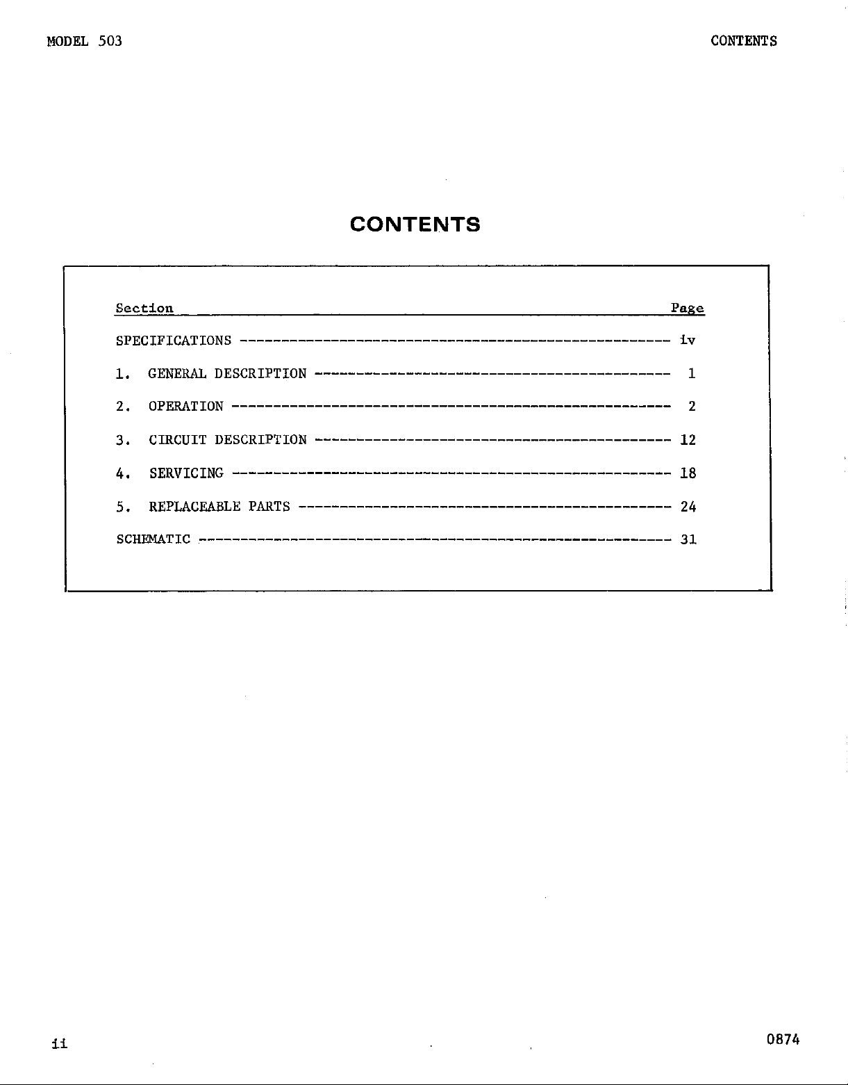
CONTENTS
Section
Page
SpECIpIC*TIONS ---------------------------------------------------- iv
GENERAI, DESCRIPTION ________-___________----------------------- 1
1.
OpE&Q-ION ----------------------------------------------------- 2
2.
CIRCUIT DESCRIPTION ------------------------------------------- 12
3.
SERVICING -_-_------------------------------------------------- 18
4.
REpL)&E&LE pm',-- ____-___________________________________-----
5.
SCHE&yJIC --------------------------------------------------------- 31
24
ii
0874
Page 3
MODEL 503
Pip;.
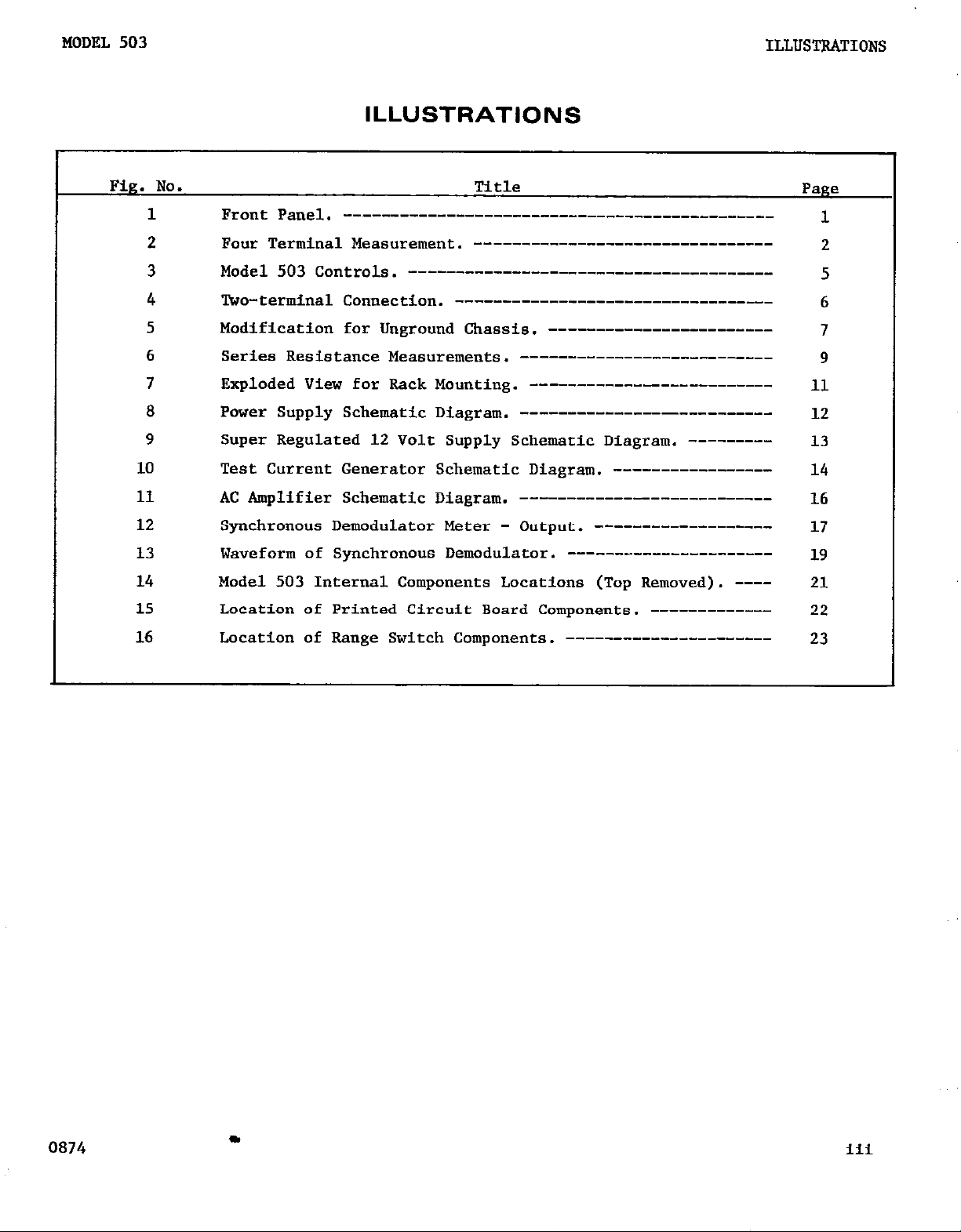
ILLUSTRATIONS
No. Title
1 Front Panel. ---------------__----------------------------
ILLUSTRATIONS
Page
1
2 Pour Terminal Measurement. -------------------------------3 Model 503 Controls. -_--__________-_-_-___________________
4 lbo-terminal Connection. ------_-_-_________-_____________
5 Modification for &ground Chassis. -----------------------6 Series Resistance Measurements. ----------_---______------
7
a
9 Super Regulated 12 Volt Supply Schematic Diagram. ---------
10 Test Current Generator Schematic Diagram. ----------------11 AC Amplifier Schematic Diagram. _--_________-__--_________
12 Synchronous Demodulator Meter - Output. _-______---_-______
13
14
15 Location of Printed Circuit Board Components. ------------
16 Location of Range Switch Components. ---------------------
Exploded View for Rack Mounting. ------------------------Power Supply Schematic Diagram.
Waveform of Synchronous Demodulator. ----------------------
Model 503 Internal Components Locations (Top Removed). ----
------------_---__________
2
5
6
7
9
11
12
13
14
16
17
19
21
22
23
0874
c
iii
Page 4
SPECIFICATIONS
MODEL 503
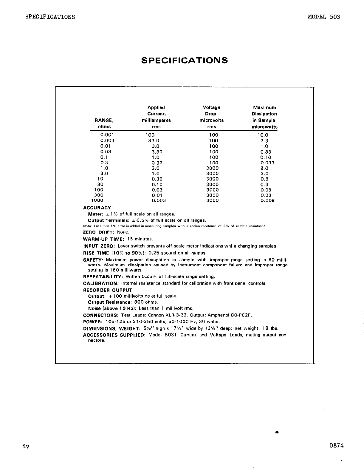
SPECIFICATIONS
Applied
C”Wl?“t,
RANGE,
oIlIll* rnls rms
0.001 100 100 10.0
0.003 33.0 100 3.3
0.01 10.0 100 1.0
0.03 3.30 100 0.33
0.1 1.0 100 0.10
0.3 0.33 100 0.033
1.0 3.0 3000 9.0
3.0 1 .o 3000 3.0
10 0.30 3000 0.9
30 0.10 3000 0.3
100 0.03 3000 0.09
300 0.01 3000 0.03
1000 0.003 3000 0.009
ACCURACY:
Meter: * 1 % of ‘“,I SCSI0 an a,, ranges.
Output Te,lni”al*: +0.5% Of ‘“II SC& an a,, ranges.
Nom Less U’S” 1% Brmr ts added I” measuring 9amp1e. with B series resctanca Of 2% Of “ample m.i.l.“E..
ZERO DRIFT: None.
WARM-UP TIME: 15 minutes.
INPUT ZERO: Lever ~wifch prevenf~ off-scale meter indications while changing samples.
Rl8E TlME 110% to 90%): 0.25 second an a11 wmges.
SAFETY: Maximum power dissipation in sample with improper range setting is 80 milli-
wets. Maximum dissipation cawed by instrument component failure and improper range
sating is 160 milliwatts.
REPEATABILITY: Within 0.25% of full-scale range setting.
CALIBRATION: Internal redstance standard for calibration with front panel controls.
RECORDER D”TPwr
Output: + 100 millivolts dc at full scale.
Output Resistance: 800 ohms.
Noise (above IO Hzl: Less than 1 millivolt rms.
CONNECTORS: Test Leads: Cannon XLR-3-32. Output: Amphenol 80.PC2F.
POWER: 105-I 25 or 2 1 O-250 YOltS, 50-1000 HZ. 30 watts.
DIMENSIONS, WEIGHT: 5%” high x 17%” wide by 13%” deep; net weight. 18 Ibs.
ACCE88DRlES 8”PPUED: Model 5031 Current and Voltage Leads; mating o”f,,“t con-
“eCtOr*.
milliamperes
Voltage
Drop.
microvolts in Sample.
ME2tdll”~
Dissipation
miorowatts
iv
0874
Page 5
MODEL 503
GENERAL DESCRIPTION
SECTION 1.
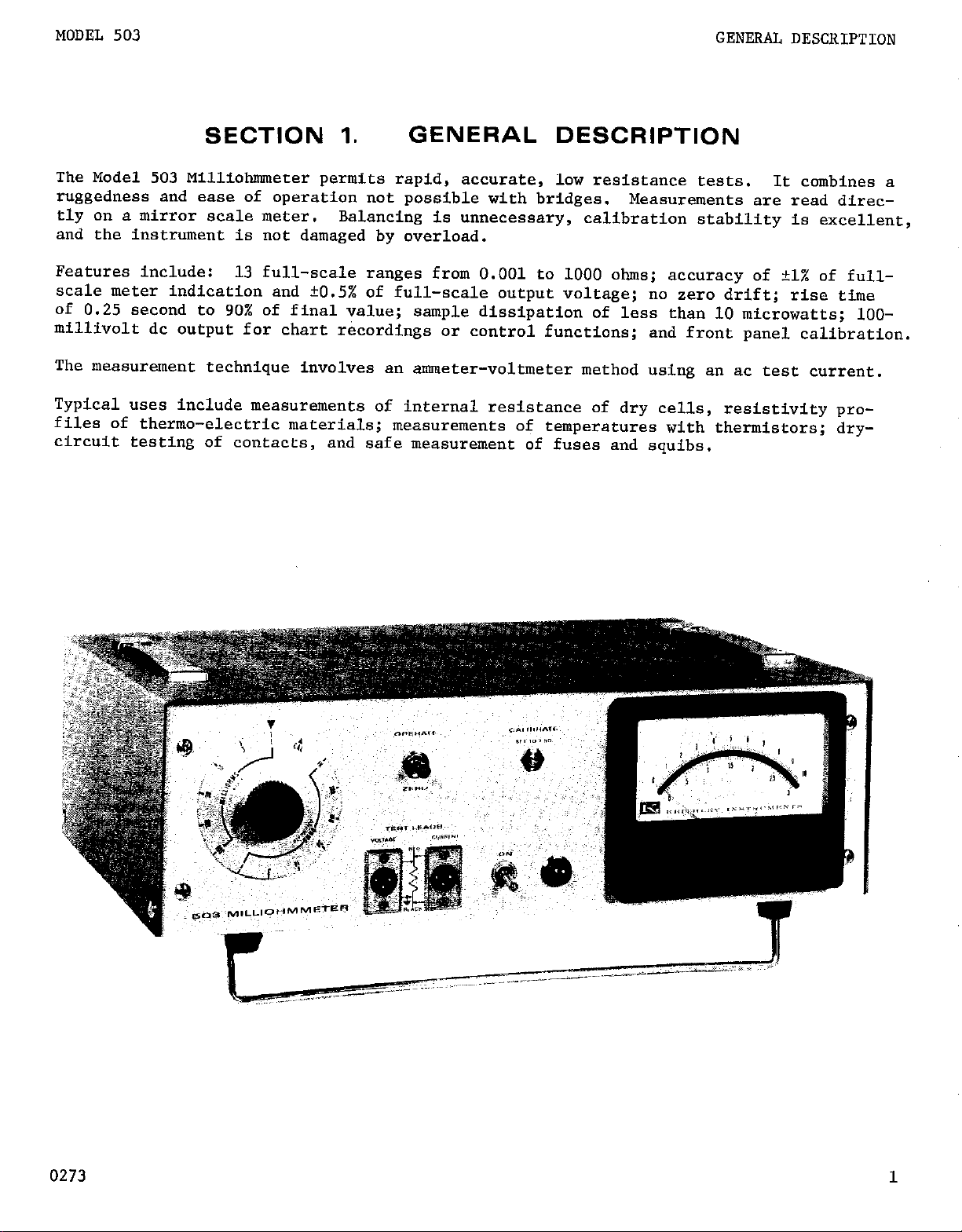
The Model 503 Milliohnuwter permits rapid, accurate, low resistance tests.
ruggedness and ease of operation not possible with bridges.
tly on a mirror scale meter.
and the instrument is not damaged by overload.
Features include: 13 full-scale ranges from 0.001 to 1000 ohms; accuracy of +l% of full-
scale meter indication and ?0.5% of full-scale output voltage; no zero drift; rise time
of 0.25 second to 90% of final value;
millivolt dc output for chart recordings or control functions;
The measurement technique involves an ammeter-voltmeter method using an ac test current.
Typical uses include measurements of internal resistance of dry cells, resistivity pro-
files of thermo-electric materials;
circuit testing of contacts,
Balancing is unnecessary,
and safe measurement of fuses and squibs.
GENERAL DESCRIPTION
It combines a
Measurements are read direc-
calibration stability is excellent,
sample dissipation of less than 10 microwatts; lOO-
and front panel calibration.
measurements of temperatures with thermistors; dry-
0273
Page 6
OPERATION
MODEL 503
SECTION 2.
2-1.APPLICAl'IONS: The Keithley Model 503 Milliohmmeter is especially useful
for accurate measurement of low value resistors; resistances of lead wires,
terminal connector contacts and welds; resistance change in conductors due
to temperature and humidity effects;
conductors; resistivity of semiconductors, contact resistance of vibrators,
relays and choppers and internal resistance of dry cells. Also for resistivity profiles of thermoelectric materials end safe measurement of squibs and
fuses.
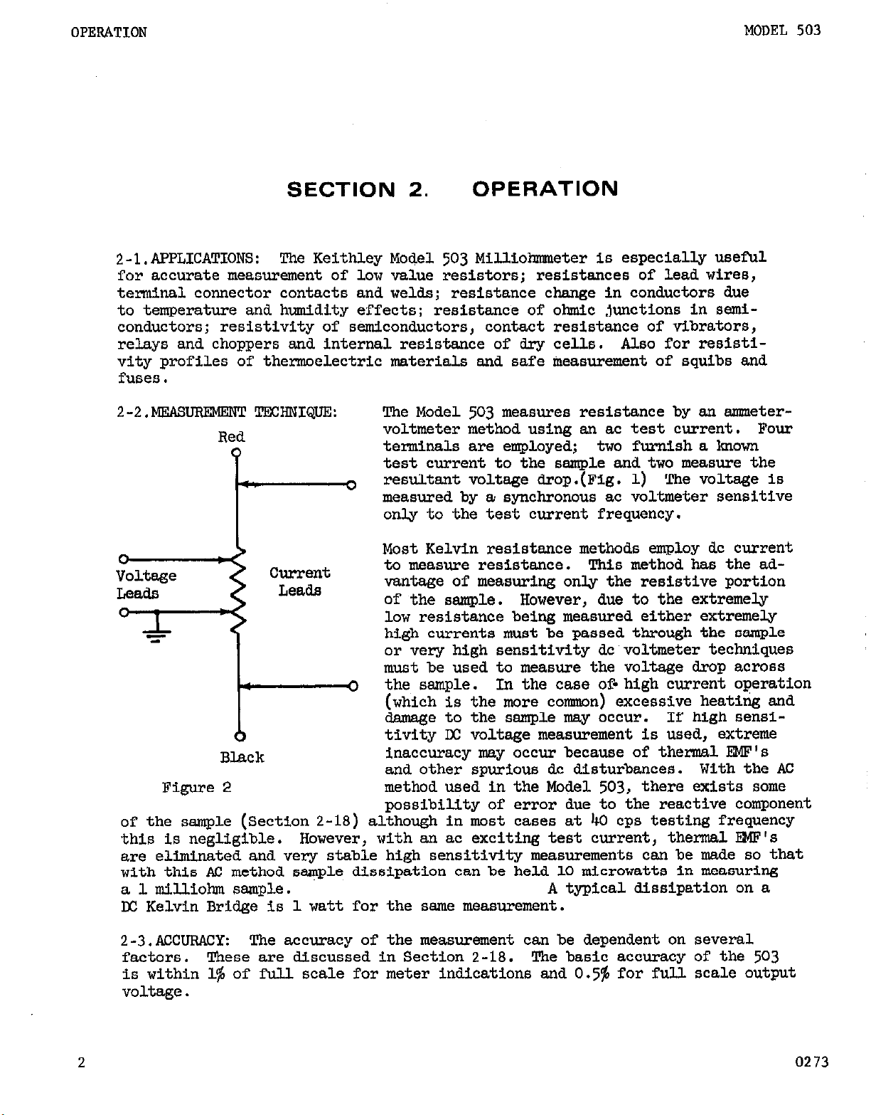
2-2.MEAsuRBMERT TECHNIQUE:
Red
0
w.
Current
Leads
*
0
Black
Figure2
of the sample (Section 2-18) although in most cases at 40 cps testing frequency
this is negligible.
are eliminated and very stable high sensititity measurements can be made so that
with this AC method sample dissipation can be held 10 microwatts in measuring
a 1 milliobm sample. A typical dissipation on a
D(: Kelvin Bridge is 1 watt for the ssme measurement.
However, with an ac exciting test current, thermal E?@'s
!Che Model 503 measures resistance by an metervoltmeter method using an ac test current. Four
terminals are employed; two furnish a known
test current to the sample and two measure the
resultant voltage drop.(Fig. 1) !Che voltage is
3
measured by a synchronous ac voltmeter sensitive
only to the test current frequency.
Most Kelvin resistance methods employ dc current
to measure resistance. !l%is method has the advantage of measuring only the resistive portion
of the sample.
low resistance being measured either extremely
high currents must be passed through the sample
or very high sensitivity dc voltmeter techniques
must be used to measure the voltage drop across
the sample.
0
(which is the more cosnnon) excessive heating and
damage to the sample msy occur. If high sensitivity LX voltage measurement is used, extreme
inaccuracy may occur because of thermal EKF's
and other spurious dc disturbances. With the AC
method used in the Model 503, there exists some
possibility of error due,to the reactive component
OPERATION
resistance of ohmic junctions in semi-
However, due to the extremely
In the case of-high current operation
2
2-3.ACcuRACY:
factors. These are discussed in Section 2-18.
is within 1% of full scale for meter indications and 0.5% for full scale output
voltage.
The accuracy of the measurement can be dependent on several
The basic accuracy of the 503
0273
Page 7
MODEL 503
2-4.RRPEATABILSl'Y: Raving once established a reading for a particular sample
measurement, it is possible to repeat within 0.25% of the full scale range setting. This assumes the connections to the sample remain fixed.
OPERATION
2-5.CALIRRATION: The
resistance standards to check its accuracy.
503
is self calibrating and thus reduces the need for
It is possible to verify the cali-
bration with or without the sample attached to the test leads. (See Sect. 2-14)
2-6.VOVIMETER SPECIFICATIONS:
Since the
503
uses a synchronous demodulator,
the voltmeter is sensitive only to signals of the test current frequency.
The sensitivity and input impedance are listed in Table 2.
TABLE2
Rms Input for Full
Remges
Milliohm
Ohm
Scale Deflection
100 uv
3000
uv
2 in
200
ohms
1 x 10⁶ ohms
2-7.TRST CURRENT CRARACTRRISTICS: The testcurrent is a square wave derived
from the transistor inverter.
justed as discussed in Section 3-2.
The frequency is about 40 cps, and can be ad-
This may be desirable if the power line
frequency is a multiple of 40 cps.
The maximum open circuit voltage is no more than 20 volts peak to peak. No
more than 80 milliwatts of power can be delivered from this source.
2-8.SPEED OF MEASUREMENT:
Fast measurements are possible by virtue of an
overall 0.25 second response (gO$ full scale) of the output voltage. A zero
switch on the front panel shorts the input to the voltage amplifier, thus
preventing off scale indication while changing samples,. Recovery from over-
load is almost instantaneous and normal operation can be immediately resumed.
2-9.wAF@MJP:
has a
15
Operation within the stated specification is-assured if the
minute period of warm-up. It can be used within one minute, but
503
measurements may not be within the accuracy specification.
2-lO.RFCORDING: Output terminals are available at the rear of the instrument.
The output is t100 millivolts across approximately 800 ohms. The output noise
level, above 10 cps, is less than 1miUivolt rms. This output is suitable
for driving digital voltmeters and servo-rebalance recorders. The accuracy of
the output is
2-11.KWER REQUIRBWWI!: The Model
frequencies from
105
to
125
0.5%
50
v0l-h or
of full scale.
503
can be powered over a range of line
cps to 1000 cps. The line voltages can range from either
210
to
250
v0lts.
No special connections or modifications
are required to operate over the range of power line frequencies.
A three prong power line cord is provided, this is to assure proper grounding
of the instrument to the power line.
2-12.CAXNET OR RACK l.KXlNTING:
The Model
503
is shipped a8 a bench instrument
unless the order call.6 for rack-sreanting. The Model Koch Rack bunting Kit
adapts the instrument for standard lg-inch rack mounting. Refer to pragraph
2-18 for conversion instructions.
02
3
3
Page 8
OPERATION
MODEL 503
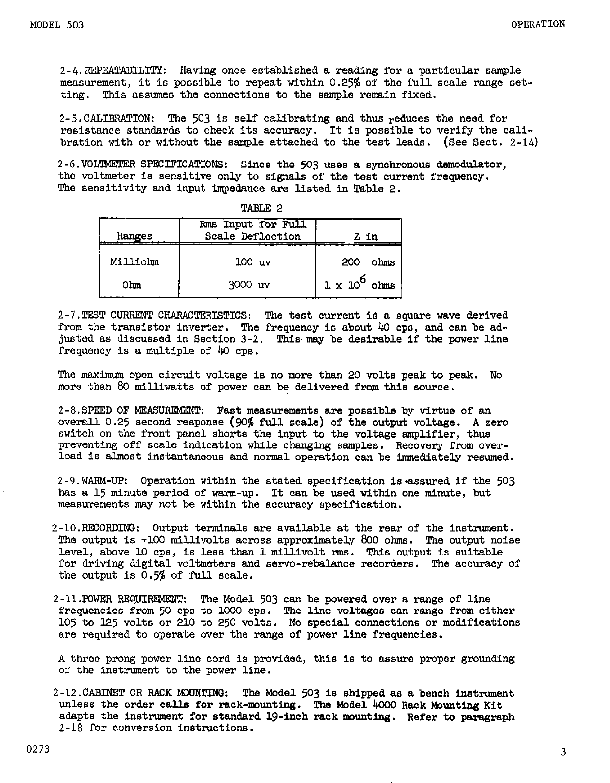
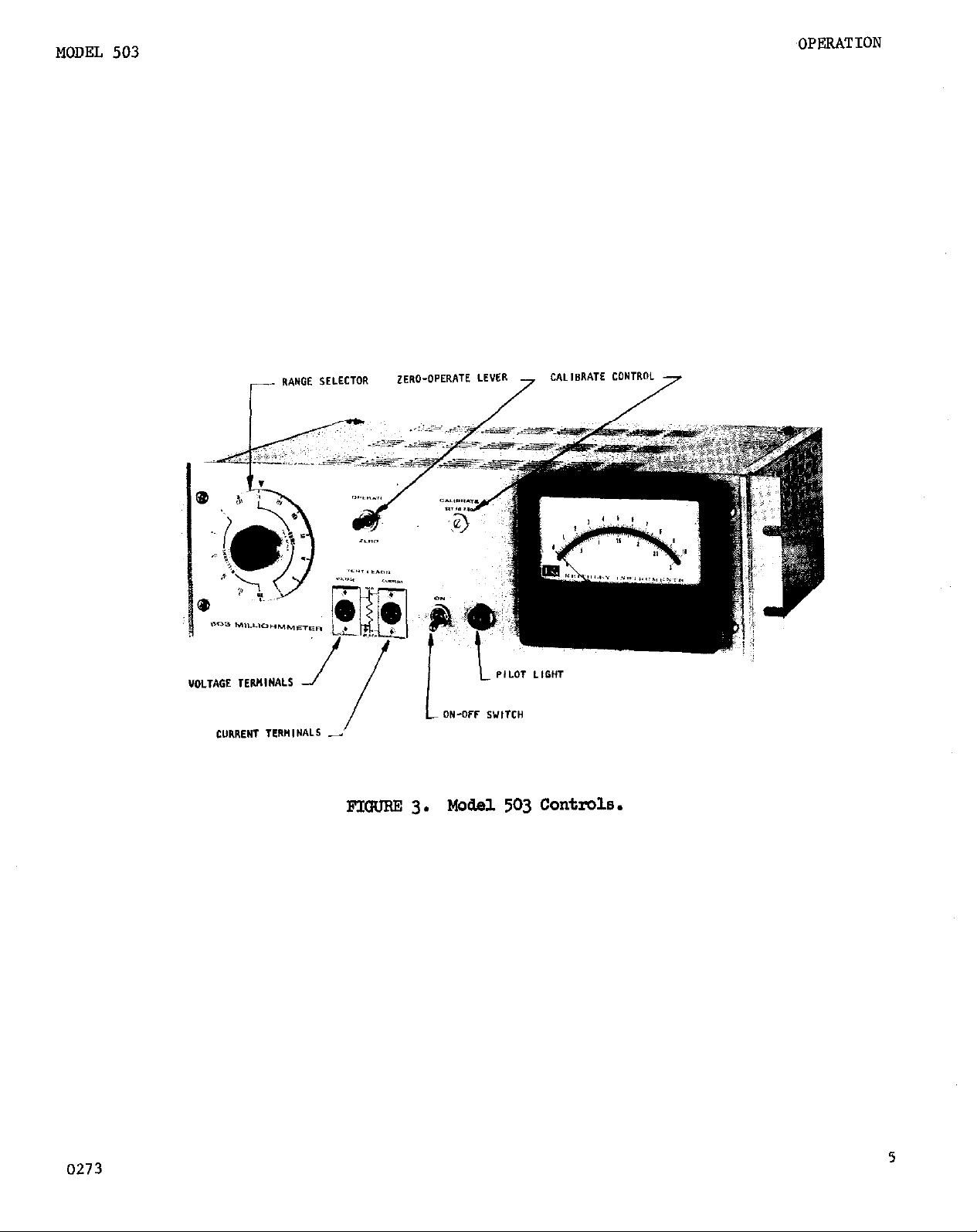
2-13.DESCFUFTION
1. RANGE SELEC!lXX
ing from 1 milX.ohm to 300 milJiohms, and seven ohm positions ranging
from lob to lOo0 ohms.
ibration. (Fig. 3)
2. ON:
indicated by the il&minated front panel pilot Lamp. (Fig. 3)
OPERATE-ZERO: This is a lever switch. 1 With the switch in the up
3.
operate) position the 503 is reaw to take measurements. In the down
zero) position the 503 is in zero check.
4.
CALIBMTE:
put voltage of the 503.
justed with a screw driver. (Fig. 3)
VOLTAGE TERMINAL%
5.
the voltmeter circuit.
can be plugged into this receptacle.
6.
CURRENT TERMINAIS:
the current source.
(Fig. 3)
OF CONTROIS AND TERMINALS:
The RANGE SELECTOR has six milliohm positions rang-
A CAL position is provided for Instrument cal-
Toggle switch is the main power switch. Presence of power is
(Fie. 3)
This control is used to calibrate the meter and the out-
It is a recessed slotted control that can be ad-
A 3-pin male receptacle is used for connection to
Pin No. 3 is at chassis ground. Either test lead
(Fig.
3)
A 3-pin male receptacle is used for connection,to
Either test lead can be plugged into this
receptacle.
7.
sis.
OUTHJT:
This provides the output voltage for recording. Pin No. 2 is at ckas-
A two terminal receptacle is located at the rear of the chas-
sis ground.
a.
RESET (503C ONLY): This unlocks the contact circuit. A g-pin recep-
tacle at the rear
of
the chassis provides connections for operation with
the contact meter.
OUTHJTCti
9.
on the chassis behind the front panel.
This is a slotted control located inside the instrument
This adjusts the value of the out-
put voltage for a full scale reading.
10.
11.
MILIJOHMS CALz This is a slotted control located inside the instru-
ment on the chassis behind the front panel.
ibrated using this control.
use.
This is a factory adjusted control and should not require attention.
KJSE:
A fuse extractor post is located on the rear of the instrument.
A low resistance standard is required for its
The milliohm ranges are cal-
For 117 volt operation use a 3 AG, $ amp fuse; for 234~volts use a 3 AG, * amp.
12.
POWER CORD:
The three-wire cord with ,the NEMA approved three-prong
plug provides a ground connection for the cabinet. An adapter to allow
operation
from
two prong outlets is provided.
0273
Page 9
MODEL 503
,OPERATION
0273
FIm 3.
140del 503 Controls.
5
Page 10
OPERATION
2-14.0UTLINE OF PFOCELJJRE:
MODEL 503
1. Connect power cord to power source.
nished with the
503.
Power line voltage and frequency range are specified
A three-wire power cord is fur-
on the rear of the instrument.
2. Set ZERO-OPERATE lever to the ZERO position. Set RANGE SELECTOR to
lOOC-ohm position.
Turn on the power.
3,
4.
CONNECTIONS: Each test lead set has two clips, one with a red insu-
lator and the other with a black insulator.
Allow 15 minute warm-up.
When making connections use
both test leads, making sure clips with like color insulators are on the
same side of the sample, (Refer to Figure 2) This is necessary to avoid
meter readings below zero.
Four terminal connections:
a.
The current leads should be attached
to the sample making sure the test current flows through the entire
sample.
This may include leads on the sample. Attach the voltage
leads being sure they are connected only across that portion of the
sample to be measured. If the terminals or the leads of the sample
are included in the voltmeter circuit, their resistance will be
included in the reading. (See Section 2-18)
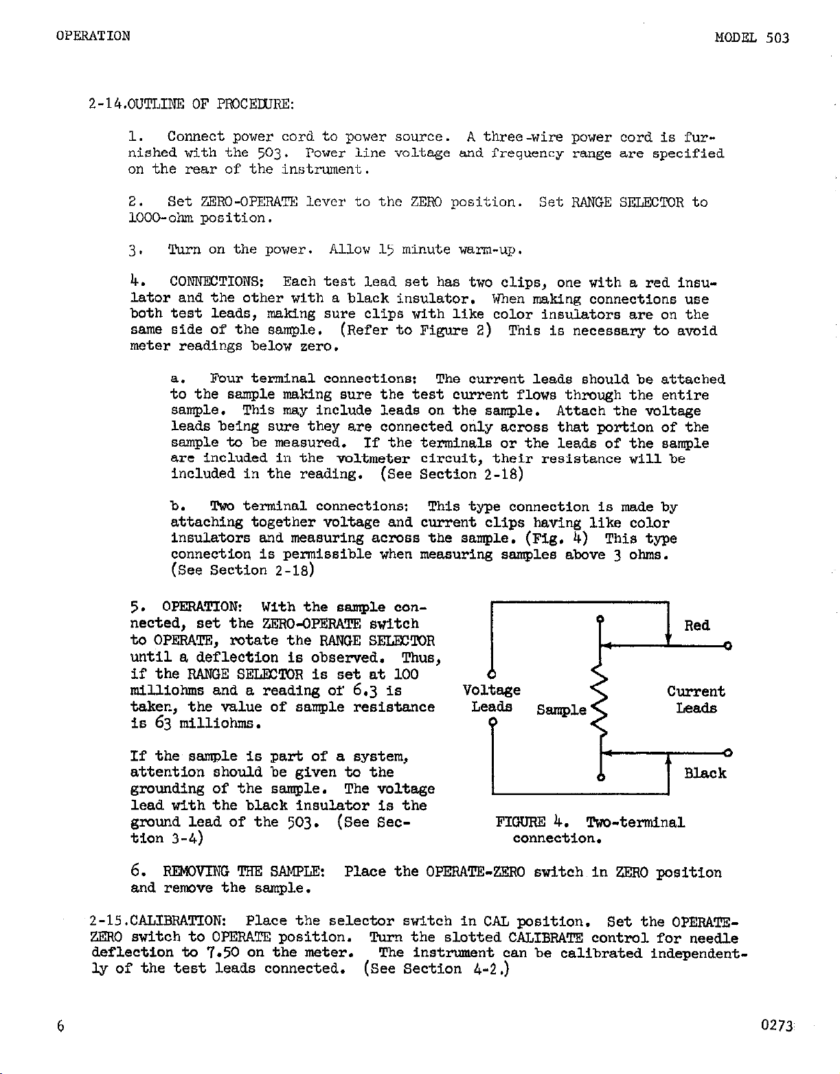
b. Two terminal connections: This type connection is made by
attaching together voltage and current clips having like color
insulators and measuring across the sample. (Fig, 4) This type
connection is permissible when measuring samples above 3 ohms.
(See Section 2-18)
5.
OPERATION: With the sample connected, set the ZERO-OPERATE switch
to OPERATE, rotate the RAWGE SELECTOR
until a deflection is observed.
if the RANGE SELECTOR is set at 100
milliohms and a reading of
6.3
is
taken, the value of sample resistance
IS
63
milliohms.
If the sample is
attention should
grounding of the
part of a system,
be given to the
sample. The voltage
lead with the black insulator is the
E;;; l..d of the
503.
(See Sec-
I
6. FtEMNING ‘I!m s&m&
Place the OPERATE-ZERO switch in ZERO position
and remove the sample.
2-15.CALIBRATION:
ZERO switch to OPERATE position.
deflection to
Place the selector switch in CAL position. Set the OPERATE-
Turn the slotted CALIBRATE control for needle
7.50
on the meter. The inst-nt can be calibrated independent-
ly of the test leads connected. (See Section
Leads
?
FIGURE
connection.
4-2.)
Sample
4.
Two-terminal
Leads
6
0273
Page 11

MODEL 503
OPERATION
Z-16. OUTPUT.
at ground.
RRATE control on the front panel calibrates the output as well as the meter.
An internal contml R125 OUTPUT CAL is adjusted at the factory to insure track-
ing between the meter and the output voltage.
If it is desired to use a recorder other than 100 millivolts, the output ter-
minals may be shunted with the following values:
After the divider is added to the output, recalibrate the instrument on the
CAL position.
CAL control.
2-lT.MEAsuREMENT OF GROUNDED SAMPLES:
be independently grounded at some point. Since the voltage test lead with the
black clip insulator is at chassis ground, errors could arise in measurement.
1.
using a two-prong power cord adaptor to remove the ground connection to
the power line. Place the instrument so that the cabinet is not touching
ground.
proper insulation.
The 503 is designed to drive a 100 millivolt recorder. The CALI-
Recorder Sensitivity
TEMPORARY MEAsuRe
Connect to the output terminals, observing that pin No. 2 is
(See Figure 14)
Resistance Value
50 m-l
10 mv
lmv
Adjust recorder sensitivity with R125, the internal recorder
FOR OCCASIONALMEASUREMENTS:
If the tilt bail is not used, the rubber feet can provide the
'Z"E
3&Gns
(tap output 7 ohms from ground)
It is possible that the test sample may
Isolate the Model 503
PgRMANENTSET-up:
2.
(such as in rack use) the followlng modification will facilitate such
measurement.
milliohm ranges; the ohm ranges are inoperative.
Remove the chassis ground connection from pin 4 of T-l and pin 3 of J-1.
Then connect pin 3 of J-1 to pin 4 of T-l.
and current test Leads will be isolated from ground.
J-l
The change allows the instrument to operate only on the
FIGlJF?E 5. Modification for unground chassis.
Should it be necessary to unground the chassis,
In this way both the voltage
(Fig. 5)
c
0273
7
Page 12

OPERATION
2-18.ACCUBACY CONSIDERATIONS:
MCDEL 503
1. MEASUFiEkKNT IN THE PRESENCE OF Ix: CUBBEETS:
sistance with dc currents present in the sample. Aninfluencing factor is
the amount of current that will saturate the voltmeter input transformer.
A 1% error in measurements, using milliohm range settings, will occur if
the dc current causes a 20 millivolt drop across the sample. The dc current
through the sample can be increased if a capacitor is put in series with
a voltmeter lead. The capacitor should be 10,000 ufd with a voltage rat-
ing greater than the dc current source voltage.
With measurements in the range from 1 ohm to 1000 ohms, a 1% error will
~cur if a current greater than 1 milliampere flows through the current
supply circuit.
age of the dc current exceeds 50 volts.
The dc sample current which will cause 1 ma to flow in the current supply
circuit may be computed from the sample resistance and the range resistor
in use.
2. INDUCTIVE ANDCAPACITIVE EFFECTS:
system and synchronous demodulation to discriminate against 60 cycle pickup and to discriminate to a degree against reactive components in the sample.
Therefore, usually, no special precautions or shielding are necessary unless
the ac fields in the neighborhood of the sample are unusually strong. The
usual cause of trouble will be due to electro-magnetic induction. Electro-
static pick-up usually is no problem at the impedance involved. A good way
to test for pick-up is to remove the current leads and leave the voltage
leads attached to the ssmple. If no reading is seen, there is no cause of
concern. If, however, there is a reading, the source of magnetic field must
be removed or the sample oriented in such a way as to minimize the reading.
The voltmeter will not be effected unless the source volt-
The Model 503 uses an ac measuring
The 503 can measure re-
Because of the ac technique employed, inductive and capacitative components
in the test impedance may cause some wave-form distortion and erroneous
readings. In practice, it has been found that the following method will
enable the user to calculate errors introduced by inductance in series with
the sample or capacitance across it. ExperimentalJy it cm be shown that
the error due to a series inductance or shunting capacitance is equal to
about 50% of what would be calculated, assuming the shunting or series
effect was due to the impedance computed for a 40 cps sine wave.
In the presence of large interfering ac fields, some needle flutter will
be noted. This will be due to a beat between the 40 cps carrier frequency
and the signal. The average value of the pointer indication will be the correct reading unless the interfering signal is exactly equal in frequency to
the carrier. In this case large errors may be encountered. However,. since
a 40 cps interfering signal is rarely encountered, there will be little
likelihood of trouble.
Coupling between the current and voltage leads can cause significant error
on the 1 milliohm rage. This can be minimized by keeping the voltage and
current leads separated and by twisting the pairs of leads to reduce the
enclosed area.
8
0273
Page 13

MODEL 503
3.
resistance may be appreciable in such cases as resistivity profile measure-
ments, or when low resistance connections to the sample cannot be made.
(See Fig.
OPERATION
ERRORS IUE M SEFIIES RESISTANCE IN CUkWEN!T AND VOLTAGE LEADS: Series
6)
Current Leads
FIGURE 6. Series Resistance Measurements
The tabulated values will give no more thau 1% errc
2
Ohm range settings
33x
full scale range
setting
: in metsurement:
T0tsr.l. resistance
in voL~.age leads 2rv
1 ohm
1oK ohms
=l
0273
9
Page 14

OPERATION
2-lV.PREPARATION FOR RACK MOUNTIEG. (See Figure 7.)
MODEL 503
1. The Model
bail.
The Model 4CCC Rack Mounting Kit converts the instrument to rack
503
is shipped for bench use with four feet and a tilt-
mounting to the standard EIA (RETMA) 1%Inch width.
Item
(See Figure 7.)
1
2
Description
Cover Assembly
Cover Assembly, Bottom (Supplied 1kggOB 1
with Model
503)
Keithley
Part No. Quantity
M23~
1
Angle, Rack llc624B
z
5
TABLW4.
2. To convert the Model
Screw, Phillips Head, lo-32 UEC-
2x4 (Supplied with Model
503)
Front Panel (Supplied with Model
503)
--
--
Parts List for Model 4000 Rack Mounting Kit.
503,
remove the four Phillips head screws at
i
1
the bottom of each side of the instrument case. Lift off the top cover
assembly with the handles; save the four screws. To remove the feet and
tilt bail from the bottom cover assembly, turn the two screws near the back.
The two pawl-type fasteners will release the cover and allow.it to drop
off. Remove the feet and the tilt bail and replace the cover (2).
Attach the pairof rack angles
3.
Phillips head screws (4) previously removed.
(3)
to the cabinet with the four
Insert the top cover assembly
(1) in place and fasten to the chassis with.the two pawl-type fasteners
at the rear.
Store the top cover with handles, feet and~tilt-bail for
future use.
10
0273
Page 15

MODEL 503
OPFJUl'ION
/o SCREW
2 COVER ASSEMBLY
L
/ “\
/@COVER ASSEMBLY
FIWJFiE 7. Exploded View for Rack Mounting.
0273
11
Page 16

CIRCUIT DESCRIPTION
SECTION 3. CIRCUIT DESCRIPTION
The Model 503 circuit consista of four basic sections; a twelve volt auper-
regulated power supply, a trenaiator dc to ac inverter circuit, e four atege
high gain vecuum tube amplifier and e silicon diode demodulator.
The twelve volt power supply operates from the line voltage and furnishes a
very closely regulated 12 volts. This voltage is used to light the tube filaments and to operate the transistor converter. The converter operates at &C
cpa.
operates the demodulator diodes,
plus supply for the ac amplifier via e rectifier-filter system.
The vacumn tube aqlifier operates following an input trensfor?ner on the milli-
ohm ranges and directly emplifiea the signel on the ohm ranges. A high degree
of gain stability is assured by a substantial feed-back factor and by the use
of cloiely reguleted pLate and filaxnent supplies.
The output obtained from the converter transformer via various windings,
YODEL 503
supplies the 40 cps test current end the B-
The output of the amplifier is synchronously demodulated by a silicon diode
bridge end the resulting dc signal operates the output circuit and the meter.
D20l R 201
Ill& -
i 1
I I-
IIE
m
I/vL
1
1
+ c201
T t
1
D202
.
c-IO.5 v
TO Q4
COLLECTOR
- .
0203
12
Figure
8.
Power Supply Schematic Diagram
0273
Page 17

MODEL 503
CIRCUIT DESCRIPTION
3-1.
mwFa SUPPLY:
(Fig. 8) The power supply consists of three parts:
1. THE AC FOWER TFMSFORMERANDFILTFR-RECTIFIERCIRCUITRY: Thepowertrenaformer, T-2, may be connected for either 117 or 234 volt operation as indi-
cated in the schemetic.
at 1 ampere and 117 volts at
The secondaries of the trenafonner supply
5 ma.
The output of the
18
volt winding is full-
wave rectified by DZO3 end D204 end filtered by C202, C2O3 and A202.
clc voltage developed across C2O3 is approximately 20 volts. Neither ter-
minal is grounded since the minus
terminal
of the regnletor is grounded at
the emitter terminal of Ql.
The output from the 117 v winding is half-wave rectified by D201 end filtered
by C201. R201 is a dropping resistor for zener diode D202. This diode is
connected between ground and the supply aide of the load resistor for transistor Qk. The purpose of this connection will be discussed below.
2.
THE SUPRR-RFEULATRD I.2 VOLTSUPF'LYz
(Fig. 9) The unregulated 20 volts
dc obtained from rectifiers and the transformer is applied to a solid state
regnletor consisting of QJ. through
Q6
and D202, D2O5, end ~206. Q5 and Q6
form e differential amplifier which compares the voltage across the output
of the regnletor (C2O5 is &cross the output) via divider R210 end R2Og to
the voltage supplied by sener reference diode D2O5. If the voltages at the
bases of Q5 and
change is further amplified by Q4, Q3 and Q2.
Q6
are not equal, the collector voltage of Q5 changes. This
The signal is finally applied
to the base of the series element in the regulator Ql. The aignel is always
of such megnitude and phase that output voltege is instantaneously brought
beclr to 12 volts. RF-14 is a forward biased diode which sets the emitter
voltage of Qk.
The collector load resistor of Q4, R2O5, is returned to minus
10 volts supplied by sener, D202. This extra reguleted voltage permits Q4
18
volts
The
0273
ov>
+>
-10.5>
1
R 206 207
1
C 205
3
R203
E
R205
R204
R206 R209
Figure 9. Super Regulated 12 Volt Supply Schematic Diagram
t12v
13
Page 18

CIRCUIT. DESCRIPTION
to operate at much higher gain than if the collector load were returned
to the unregulated side of the supply and permits linear operation of
Q4 with widely varying input voltages.
tant contribution to the performence of the power supply. Q3 and ~$2 are
cascaded emitter followers whose function is to increase the current gain
of the series transistor, Ql.
provide stability at high temperatures since they make available a backbias current equal to the leakage current of the series transistors at a
temperature of approxSmately &OC.
tion of the power supply. The twelve volts at the output of the regula-
tor powers the filaments of Vl and V2 and the pilot Lamp E-1.
3. 40 CPS TRANSISMR STATIC INVERTER CIRCUIT: (Fig. 10) A portion of
the regulated I2 volt power is also used as the supply for a dc converter
consisting of the following parts:
Q8, diodes IX?07 and D208, capacitors
Pi212 and R213. The operation is as follows: Transistors Q7 and Q8 are
connected across the 12 volt supply through their emitters and the centertap of the 12 volt winding of T3.
from another winding on T3.
driven hard on while the other is cut off.
core of T3 reaches saturation.
keep the on transistor fully conducting and its collector current decrea-
ses.
This causes the polarity of the feed-back winding to change and the
transistor which was cut off now conducts and the conducting transistor is
cut off. The frequency of oscillation is controlled by the transformer
constants. In this case the frequency was picked to be 40 cps. The ten
volts rms secondary winding is used to provide the test signal and provides a 20 volt peak-to-peak square-wave which is used with series re-
sistors RI28 through Rl39 to provide the proper test current for each
range. Diodes DlOl and D102 limit the output voltage when the current
leads are open circuited.
This connection makes an impor-
R203 and R204 are added to the circuit to
C204 prevents high frequency oscilla-
Transformer T3, transistors Q7 and
~206
and C207, and resistors R2ll,
The bases receive positive feed-back
The phasing is such that one transistor is
This cycle lasts until the
At this point the transformer can no longer
MODEL 503
TEST CURRENT
SVJITCH
R213 +260
>
I _
I
7
Y
Figure 10. Test Current ,Generator Schematic Dlegrsm
14 0273
Page 19

MODEL 503
CIRCUIT DESCRIPTION
The 270
fier.
b'and
Since the stability of the converter circuit depends only on the
volt Winding pmVideS a B+
of 260 volts for the vacuum tube ampli-
The signal is rectified by D207 and
R213.
~208
and filtered by C207 a and
stability
of the twelve volt power supply, very close regulation is obtained for all
potentials used in the circuit.
100 to
3-2.mT
130
volts have no effect on the instrument.
cm G-R:
(Fig. 10) As mentioned above, the test current is
derived from the 10 volt winding of T-3.
Consequently line voltage variations from
Since Q7 and. Q8 bottom on each half
cycle, the amplitude stability of the signal &pen& only on the 12 volt supply,
and is therefore as stable as the well-regulated I2 volt supply. The circuit
is not particularly critical as to frequency or wave-form. However, e nearly
Perfect square-wave is generated and the frequency is stable to better then a
few percent.
The current signal is varied to provide the change in range except between
300 milliohms and 1 ohm where the input transformer is removed from the circuit .
The variation is accomplished by switching resistors
with each current range.
Rlti through ~142 are used in conjunction with RI28
~128
through R139
to keep a constant load on the current source winding to insure a high order
of accuracy.
rent leads to plus or minus
Diodes DlOl and DlO2 limit the open-circuit voltage in the cur-
0.5
volts.
3-3.!ciaAc VACDUM-mvom:
put signal passes through transformer T-l.
(Fig. 11) On the Milliohm Renges the in-
This transformer has approximately a 70:1 step-up ratio and improves the impedance match between the voltage
signal and the input grid by a factor of
5ooO:l.
On the ohm ranges, where a
Larger signal is obtainable, the transformer is switched out so that its in-
put impedance will not shunt the resistance being measured. Accordingly, on
the Milliobm ranges, the input resistance is about 200 ohms.
On
the Ohms
ranges, the input resistance is one megohm.
The input signal is fed into qhe input of the amplifier either through Tl or
around it, depending on range, through Sl, the OPERATE-ZERO switch. This switch
is of the make-before-break variety to prevent switching transients. Following the switch is C102, the input blocking capacitor and Rl.01, the input resistor of the feed-back netwdrk.
R102 connects the feed-back signal to the
input grid so that the input grid signal is the difference between the input
signal and the feed-back signal or, as it is usually termed, the error signal.
The error signal is amplified by a standard three stage ac amplifier consist-
ing of Vl and.V2a.
V2b is an output cathode-follower which drives the feed-
back loop, Rll8, R143, RI& and RU5; and the meter and output circuits.
The gain of the smplifier is varied slightly to compensate for the absence or
presence of the input transformer by shunting RU.4'and Rl45 across R143 in
the Milliohm position.
milliolnu ranges.
The divided output of Rl18 and R143 through R145 is applied
to RlG2 and returned to the input, completing the feed-back loop.
The MILLIOHM TRIM control is used to calibrate the
A feed-
back factor of 40 db assures high gain stability. The fact that all potentials
used in the smplifier are closely regulated, also helps assure a high degree
of gain stability and complete freedom from line bounce.
0273
15
Page 20

CIRCUIT DESCRIPTION
tu
>
%
2
MODEL 503
16
5
ml
91
“T
FQur&ll. AC Amplifier Schematic Diagram
g
0273
Page 21

MODEL 503
The amplifier is stabilized against low frequency oscillation by two sets
phase-advance interstage couplings, ~106, C105, R106 and R107 between the
two halves of Vl and by CllO, Clog, R1l.l and Rll2 between Vlb and V2a.
network introduces an appropriate attenuation and phase lead to prevent os-
cillation and give adequate phase margin. C104, R105; ~108; and Cl13 and
Rll6; are individual high-frequency oscillation stoppers.
CIRCUIT DESCRIPTION
Each
3-4.!lXE SYNCHXONOUS
V2b is coupled through Cll5 and Rllg to a demodulator bridge circuit con-
sisting of D103 through DlO6. The bridge is driven through Rlk6 and R147 from
the collectors of Q7 and Q8. Since the center tap of the collector winding is
at ground, the drive signal is balanced to ground. When the junction of D103
and DlO5 is positive with respect to the junction of DlO4 and D106, the diodes
are conducting and the junction between Rllg and RI20 is effectively grounded.
When the polarity is reversed, the bridge is open circuited. Therefore, the
signal is rectified in this manner.
and then is split.
the output.
panel.
this potentiometer is used to correct the meter reading if necessary. RI25
allows calibration of the recorder terminal.
On the CAL position of the range switch, RI27 is switched in and
RI21 is the calibration control.
DEMXLWICR, METERANDOlJTPDT: (Fig. 12) The output of
The output travels through ~120, ~l21
Part of the current drives the meter and the remainder
It is located on the front
RI22
RI24
>-
0273
R
T
A
TRANSISTOR
COLLECTOR
ae
Dl06
DIOS .L
ZERO
BAL
Figure 12.
R
M
G I
I T- I
A
TRANSISTOR
COLLECTOR
at
Synchronous Demodulator Meter - Output
1
O-I
MA
Rl2f
17
Page 22

SERVICING
MODEL 503
SECTION 4.
The Model 503 should not require periodic maintenance. Occasional
verification of the calibration (either section 2-14 or 4-2) and
the dc balance (zero balance) should reveal any need for adjustment.
If difficulty is encountered, read completely the following material:
4-1. Trouble Shooting Guide
Servicing is quite straight forward as the 503 employs only two
vacuum tubes and eight transistors,
operated within their ratings.
components are used.
The usual caution should be observed when soldering to the printed
circuit board as excessive heat will damage the board,
In servicing, bear in mind all operating voltages are obtained from
the 12 volt transistor regulator, either directly or through the
transistor inverter.
Reference should be made to Circuit Schematic DR 146280 for voltage
values and other circuit parameters.
SERVICING
all of which are conservatively
No matched or critically selected
In case of complete failure to operate, the fuse, line cord and
power source should all be checked.
factory, use the following detailed service procedure to isolate
the trouble:
POWER SUPPLY:
1.
THE AC POWER TRANSFORMER AND FILTER RECTIFIER CIRCUITRY
a.
(Figure 8):
tion with ZERO OPERATE switch in ZERO position.
transistor Q-l from the circuit and measure the voltage
across C203.
VTVM) . If approximately 25 volts dc is indicated, this
portion of the circuit is in proper working order. Note
that neither terminal of C203 is grounded.
Measure voltage across D202, which should be between -9
to -12 volts with respect to ground. If not, check
diodes D201 and D202.
b. THE SUPER REGULATED 12 VOLT SUPPLY (See Figure 9): Re-
place transistor Q-l in the circuit. Determine that the
regulated 12 volts across C205 does not vary more than 5
mv with line voltages from 105 volts to 125 volts.
a variable autotransformer to supply the line voltage.
(General Radio Variac).
Set the RANGE SWITCH to the 3 milliohm posi-
(See schematic notes for recommended type
If these are all found satis-
Remove
Use
18
If no voltage is present or the 12 volts are not regulated, check components in this portion of the circuit.
0577
Page 23

MODEL 503
2.
40 CFS TRANSISTOR INVRRTER (Figure 10): .With the range switch
set at 3 milliohms, connect the current test leads to an oscillo-
scope.
of about 20 volts. If thisis present,
across C2Op.
Observe a 40 cps square wave with a peak to peak amplitude
measdre
+260
volts dc
If no square wave is observed, or the B+ is absent,
check the components in this portion of the circuit.
SWVICING
NOTE:
FOR SECTIONS
3
AND
4
THE RANCE SWITCH SHOULD BE IN CAL POSITION
WITH THE Z,li'RO-OmD SWITCH IN THE OPERATE POSITION.
THE AC VACUCM TUBE VOLIKZTER. (Figure 11): Be sure both vacuum
3.
tube filaments are heated and the pilot lsmp is lit. Since the
pilot lamp is in parallel with the filament of Vl and the combination is in series with the filament of V2 across the I2 volt
regulator, some service information is provided by its brilliance.
If it lights normally, .it may be assumed the supply is working
properly.
out.
pilot itself is open.
If it is brighter than normal, Vl is probably burned
If the lamp is not lit, either V2 is burned out, or the
The instrument will operate without the
pilot lamp, but since the life of Vl will be reduced, it should
be replaced.
If it is determined the tubes are operating proper& proceed as
follows:
peak to peak square wave.
Measure at the iunction of Cl02 and RlOl a 4 millivolt
This indicates the test current is
properly reaching the amplifier through the range switch. Should
there be no signal, or one of improper magnitude. inspect the range
switch for faulty operati,>n or component failure.
Next, check the voli;age between pin 8 ,:f V2 and ground. This
should be a square wave voltage of abcu~t 10 volts peak to peak.
A distortion in/or absence o; this signal indicates a faulty
AC amplifier.
0273
4.
SYNCHRONOUS DRMCIXJLA~R - METER OllTKlT (Figure 12): Connect an
oscilloscope to the ,Junction of !i.-119 and RI.20 and compare this
wave forn,with Figure 13.
Figure
13
A distortion or absence of this wave form Is an indication of a
faulty demodulator.
19
Page 24

SERVICING
4-3.
CALIBRATION:
1000 range.
is properly calibrated. If the user
The procedure of Section 2-14.calibrates the 503 on then
Other ranges should be within specification once thisrange
wishes
to further verify the
CALIEGWPION, or to calibrate for a given range or point, the following
procedures are reconunended:
1. OHM RANGES: A standard resistor of at least 0.05% accuracy is
reconrmended. ~T'he standard should be selected to 3/4 of full scale
of range in question, or to the value of the measurement to be
made.
The slotted control on the front panel will adjust the
meter needle for proper deflection.
MODEL 503
2. MILLIOHMRWG~:
low value standard resistor is required. Leeds & Northrup Type
4221-B, 100 milliohms; Type 4222-B - 10 milliohms: and Type 4223-B,
1 milliohm are all suitable. Using one of these resistors or
their equivalent, adjust the "MILLIOHM CAL'" (Figure 14) for the
proper meter reading.
To calibrate the milliohm ranges,. an appropriate
20
0273
Page 25

MODEL 503
SERVICING
0273
FIalm 14.
Model 503 Internal Component6 Tacations (Top Removed).
21
Page 26

Page 27

D102
R137
7
R134
rR133
.31
.R130
\ \
\ b129
\-R127
Page 28

REPLACEABLE PARTS MODEL 503
5-1.
SECTION 5;
REPLACEABLE PARTS LIST. The Replaceable Parts List describes the com-
REPLACEABLE PARTS
ponents of the Models 503 and 503C Milliohmmeters and 5031 Current and Voltage
Leads. The List gives the circuit designation, the part description, a suggested manufacturer, the manufacturer's part number and the Keithley Part Number.
The name and address of the manufacturers listed in the
“$ffg,
Code" column
are contained in Table 6.
5-2.
HOW TO ORDER PARTS.
a. For parts orders,
include the instrument's model and serial number, the
Keithley Part Number, the circuit designation and a description of the part.
All structural parts and those parts coded for Keithley manufacture (80164)
must be ordered from Keithley Instruments, Inc.
listed in the Replaceable Parts List,
completely describe the part, its
In ordering a part not
function and its location.
Order parts through your nearest Keithley distributor or the Sales
b.
Service Department, Keithley Instruments, Inc.
CbVar
CerD
Comp
CompV
DCb
EMC
ETB
ETT
f
ampere
Carbon Variable
Ceramic, Disc
Composition
Composition Variable
Deposited Carbon
Electrolytic, metal cased
Electrolytic, tubular
Electrolytic, tantalum
farad
Mfg.
MtF
Mil. No.
MY
R
P
P
V
Var
Manufacturer
Metal Film
Military Type Number
Mylar
pica (10-l*)
micro (10m6)
volt
Variable
24
k
M or meg
m
kilo (103)
mega (106) or megohms
milli (10-3)
TABLE 5.
Abbreviations and Symbols.
w
ww
WWVar
watt
Wirewound
Wirewound Variable
0273
Page 29

MODEL 503
REPLACEABLE PARTS
MODELS 503, 503C REPLACEABLE PARTS LIST
(Refer to Schematic Diagram 14628D for circuit designations.)
CAPACITORS
Circuit
Desig. Value Rating
Cl01
Cl02
Cl03
Cl04
Cl05
Cl06
Cl07
Cl08
Cl09
Cl10
Cl11
Cl12
Cl13
b114
Cl15
Cl16
Cl17
c201
c202
C203
C204
C205
.Ol vf
0.1 pf
100 pf
220 pf
1 Kf
.005 pf
100 pf
.02 pf
1 {lf
.047 uf
100 pf
20 IJf
.002 vf
270 pf
10 pf
56
jpf
56 pf
20 pf
500 uf
500 I*f
.Ol i.Lf
500 pf
50 v
50 v
15 v
1000 v
200 v
1000 "
15 v
1000 "
200 v
200 v
15 "
250 v
1000 "
500 v
200 "
6v
6v
250 v
50 "
50 v
1000 v
25 v
Mfg. Mfg.
TYPO
MY
MY
ETB
CerD
MY
CerD 72982
ETB 72699
CerD 72982
MY
MY
ETB
ETB
CerD
Mica
PMC
ETT
ETT
ETB
FNC
EMC 14655
CerD 72982
FM2 14655
Code
84411 601PE
84411 601PE
72699
72982
13050 107-21
.13050
14655
7.2689 TDlOO-15
56289
72982
84171
72354 X10316
05397 K56-J6KS
05397 K56-J6KS
56289
14655
Keithley
Part No.
TDLOO-15
831X5R221K
81125V502P C22-.005M
TDlOO-15
841Z5V203P
107-21
WMF2S47 C66-.047M
TVA1508
8OlZ5V202P
DM15-271J
TVA1508
AA0160
AA0160
811Z5V103P
AA0120
Part No.
C41-.OlM
C41-O.lM
Cll-100M
c22-22OP
C66-1M
Cll-100M
C22-.02M
C66-1M
Cll-100M
C27-20M
C22-.002M
C21-270P
C69-10M
C70-56M
C70-56M
C27-20M
C57-500M
C57-500M
C22-.OlM
C58-500M
0576
C206
C207
Circuit
Desig.
DlOl Rectifier, lA, 800V
Dl02 Rectifier, lA, 800V lN4006
D103
D104
D105 Silicon
DlO6 Silicon
D107 Silicon lN645
D201 Rectifier, lA, 800V
D202 ZCSX?r
0.22 pf
40-40-2oKf 450 "
TYPO
Silicon lN645 01295 RF-14
Silicon
50 "
MY
ENC
Number
lN4006
lN645
lN645
lN645
lN4006
lN715
84411 601PE
56289
DIODES
TVL3786
Mfg.
Code
MOT
MOT
01295
01295
01295 RF-14
01295
MOT
12954 DZ-22
C41-0.22M
C33-40/40/20M
Keithley
Part No.
RF-38
RF-38
RF-14
RF-14
RF-14
RF-38
25
Page 30

REPLACEABLE PARTS
MODEL 503
DLOIIES (Cant ’
Circuit
Desig.
Type
D203 Silicon
Number
lN1563A 04713
D204 Silicon lN1563A
D205 ZellGX
D206 Silicon
~207 Rectifier, lA, 800V
D2Og Rectifier, lA, 800V
lN936 04713
lN645 01295
1~4006
1~4006
d)
Mfg.
C0de
04713
MOT
MOT
D209 Silicon lN645 01295
MISCELLANEOUS PARTS
Circuit
Desig. Description
DS-1
---
Pilot Light Assembly, Red lens (Mfg.
No. 5100)
Bulb, Miniature bayonet base (Mfg.
No. 47)
Fl (117 v) Fuse, 0.5 amp, (Mfg. No. 312.500)
Fl (234 v)
---
Fuse, 0.25 amp, (Mfg. No. 3120.25)
Fuse Holder (Mfg. No. 342012)
Keithley
Part No.
RF-19
RF-19
DZ-5
RF-14
RF-38
RF-38
RF-14
Mfg.
Code
Keithley
Part No.
72765 PL-5R
08804
PL-4
75915 W-6
75915 FU-9
75915 FH-3
Jl
52
---
53
---
54 (c)
J5 Cc)
---
Kl (c)
Ml (4
$11 (c)
Pl
---
Receptacle, VOLTAGE (Mfg. No. XLR-3-32)
Receptacle, CURRENT (Mfg. No. XLR-3-32)
Jacb, Mate of Jl and J2 (Mfg. No.
XLR-3-11C)
Receptacle, Microphone, OUTPUT
(Mfg. NO. 80PC2F)
Plug, Microphone, Mate of 53 (Mfg.
No. 80MC2M)
Receptacle, Output (Mfg. No. 126-221)
Same as 54, but does not have jumper
Plug, Mate of J4 and 55 (Mfg. No.
126-220)
Relay, SPDT
Meter
Contact Meter
Power Cord Set, 6 feet (Mfg. No.
4638-13)
Cable Clamp (Mfg. No. SK-6~-1)
71468 cs-71
71468 cs-71
71468 CS-72
02660
02660
02660
02660
80164
CS-32
cs-33
CS-81
CS-82
RL-3
80164 ME-39
80164 ME-42
93656
co-5
28520 cc-4
26
(a) Used only on Model 503.
(c) Used only on Model 503C.
0576
Page 31

MODEL 503
REPLACEABLE PARTS
MISCELLANEOUS PARTS (Cont'd)
Circuit
Desig. Description
Sl
Switch, SPDT, OPBRATE - ZERO (Mfg. No.
3003DL)
s2
---
--s3
Rotary Switch less components, Range
Switch Assembly with components, Range
Knob Assembly, Range Switch
Toggle Switch, DPDT, ON (Mfg. No.
20905-FR)
S4 Cc)
s5
Tl
T2
T3
Pushbutton Switch (Mfg. No. 202)
Slide Switch
Transformer, Input
Transformer, Power
Transformer, Inverter
Circuit
Desig. Value
Rating
RESISTORS
Type
Mfg.
Code
82389
80164
80164
80164
04009
82389
80164
80164
80164
80164
Mfg. Mfg.
Code
Part No.
Keithley
Part No.
SW- 59
SW-114
14722B
153638
SW-14
SW-35
SW-151
TR-53
TR-59
TR-55
Keithley
Part No.
RlOl
R102
R103
R104
Rl05
R106
1Ml
1M l%, l/2 w
470 kQ
4.7 m lO%, l/2 w
12
kl
10 B-2
R107
R108
R109
RllO
Rlll
R112
R113
Z?,
470 kG
15 ul
10 m
1f-G
470 n
R114 100 k0
R115
R116
R117
R118
R119
R120
390 IG
10 lul
10 ko
1m
lksl l%, l/2 w
1.8 IQ
l%, l/2 w
l%, l/2 w
lO%, l/2 w
lO%, l/2 w
lO%, l/2 w
lO%, l/2 "
l%, l/2 w
lO%, l/2 w
lO%, l/2 w
lO%, l/2 w
lO%, l/2 w
lO%, l/2 "
lO%, l/2 w
lO%, l/2 "
lO%, 2 w
l%, l/2 w
l%, l/2 w
(c) Used only on Model 503C.
MtF
MtF
DCb
camp
camp
camp
camp
Comp
DCb
camp
camp
camp
camp
camp
camp
camp
ComP
MtF
ww
ww
07716
CEC
07716 CEC
79727
CFE-15
01121 EB
01121
01121
01121
EB
EB
EB
01121 EB
79727 CFE-15
01121 EB
01121
EB
01121 EB
01121 EB
01121
EB
01121 EB
01121
01121
07716
01686
01686
EB
HB
CEC
E-30
E-30
Rll3-1M
Rll3-1M
RlZ-470K
Rl-4.7K
Rl-12K
Rl-1OM
Rl-1M
Rl-4.7K
RlZ-470K
Rl-15K
Rl-1OM
Rl-1M
Rl-470
Rl-100K
Rl-390K
Rl-1OK
R3-10K
Rll3-1M
R58-1K
R58-1.8K
0273
27
Page 32

REPLACEABLE PARTS
MODEL 503
RESISTORS (Cont'd)
Circuit
Desig. Value Rating
R121
R122
R123
R124
R125'
R126
R127
R128
R129
R130
R131
R132
R133
R134
R135
R136
R137
R138
R139
R140
1kO
2.5 kn
500 R
2.5 k.0
200 $2
700 n
750 n
100.5 0.
301.5 R
1 wl
3k.Q
10 wl
30 ksl
3.33 kfl
33.3 ko
100 IQ.
333.3 ko
1M-l
3.33 Ml
50 n
lO%, 3 w
l%, l/2 w
l%, l/2 w
l%, 112 w
lO%, 5 w
l%, l/2 w
O.l%, l/2 w
lO%,
lO%, l/2 w
O.l%,
O.l%, l/2 w
O.l%, l/2 w
O.l%, l/4 w
O.l%, 112 w
O.l%, l/4 w
O.l%, l/4 w
O.l%, l/4 w
O.l%, 1 "
O.l%, 1 w
l%, l/2 w
l/2
112
TYPO
WWVar
ww
ww
ww
WWVar 71450
ww
ww
w
ww
ww
ww
w
ww
ww DALE
ww
ww
ww 15909
ww DALE
ww
ww
MtF 07716
ww 01686
Mfg. Mfg.
Code
Part No.
37942 - RlOOOL
01686
01686
01686
E-30
E-30
E-30 R58-2.5K
AW
01686
15909
E-30
1252 R70-750
01686
01686
15909
15909
1252 R70-1K
1252 R70-3K
MFF-1OK
15909
15909
1195 R56-30K
1252 R70-3.33K
1195 R56-33.3K
MFF-100K R-169-1OOK
DALE
DALE
MFF-333.3 R-169-333.3K
MFF-lM
MEFT-8 R59-3.33M
E-30
Keithley
Part No.
RP3A-1K
R58-2.5K
R58-500
RP3A-200
R58-700
R72-100.5
R72-301.5
R-169-10K
R-169-1M
R58-50
R141
R142
R143
R144
R145
R146
R147
R148
R201
R202
R203
R204
R205
R206
R207
R208
R209
R210
R211
R212
11.1 Q
3.33 R
500 0.
235 R
100 R
lko.
1 kn
100 Q
27 k~
1.5 R
10 kn
680 n
10 kl
300 cl
3.9 k+o
3.9 kn
900 n
a300 R
100 n
1.5 m
l%, l/2 w
l%, l/2 w
l%, l/2 w
l%, l/2 w
D
lo/., 5 w
lO%, l/2 w
lO%, l/2 w
30%, l/2 w
lO%, 1 "
5%, 10 w
lO%, l/2 w
lO%, l/2 w
lO%, l/2 w
l%, 112 w
lO%, l/2 w
lO%, l/2 w
l%, 112 w
l%, 112 w
lO%, l/2 w
lO%, l/2 w
DCb
DCb
ww
ww
WWVar
camp
camp
compv
camp
ww
79727
79727
01686
01686
71450
01121
01121
71450
01121
94310
01121
01121
camp
ww
COrnP
01121
01686
01121
01121
01686
01686
camp
01121
camp 01121
CFE-15
CFE-15
R12-11.1
R12-3.33
E-30 R58-500
E-30
AW
EB
EB
R58-235
RP3A-100
Rl-1K
Rl-1K
45 RPlZ-100
GB RZ-27K
FR-10 R5-1.5
EB
EB
EB
Rl-1OK
Rl-680
Rl-1OK
E-30 R58-300
EB
EB
E-30
E-30
EB
Rl-3.9K
Rl-3.9K
R58-900
R58-300
Rl-100
EB Rl-1.5K
28
* Nominal value, factory
set.
0576
Page 33

MODEL 503
REPLACEABLE PARTS
RESISTORS (Cont'd)
Circuit
Desig.
R213 3.3 ko
R214
R215
R216
Circuit
Desiec.
9":
Q5
Q6
9":
Value
1n
2.2 kJl
1n
Rating
lO%, 1 w
l%, l/2 w
lO%, l/2 "
l%, l/2 w
Mfr.
Desig.
2N1535
40319
2N1381
2~1381
2N1381
2N1381
2N5193
2N5193
Mfr.
5Ps
Comp 01121 GB-332-10% R2-3.3K
DCb
Comp
DCb
TRANSISTORS
Mfr.
Code
04713 TG-7
02735 TG-50
01295
01295 TG-8
01295
01295
04713
04713
VACUUM TUBES
Code Desig.
79727 CFE-15-W R12-1
01121 EB-222-10% R1-2.2K
79727 CFE-15-lR RlZ-1
Mfr.
Keithley
Part No.
TG-8
TG-8
TG-8
TG-107
TG-107
Keithley
Part No.
Circuit
Desig.
Vl
v2
Description
Test
Two Alligator Clips (Mfg. Series 60)
Jack (Mfg. No. XLR-3-11C) 71468
lead, 48 inches
Mfr.
Desig.
7025
6U8 81453 KV-6U8A
MODEL 5031 REPLACEABLE PARTS LIST
Mfr.
Code
73445 EV- 7025
Keithley
Part No.
Mfr.
Code
80164
76545
Keithley
Part No.
14731B
AC-1
CS-72
0874
29
Page 34

01121
Allen-Bradley Corp.
Milwaukee, Wis.
02660
Amphenol-Borg Electronics Corp.
Broadview Chicago, Illinois
01295
01686
04713
05397
07716
08804
12954
13050
14655
15909
28520
37942
56289
71450
7146%
72354
72699
Texas Instruments, Inc.
Semi-Conductor-Components Division
Dallas, Texas
RCL Electronics, Inc.
Riverside, N. J.
Motorola, Inc.
Semiconductor Products Division
Phoenix, Arizona
Kemet Co.
Cleveland, Ohio
International Resistance Co.
Burlington, Iowa
Lamp Metals and Components
Department G. E. Co.
Cleveland, Ohio
Dixon Electronics Corp.
Scottsdale, Arizona
Potter Co.
Wesson, Miss.
Cornell-Dubilier Electric Corp.
Newark, N. J.
Daven Co.
Livingston, N. J.
Heyman Mfg. Co.
Kenilworth, N. J.
Mallory, P. R., and Co., Inc.
Indianapolis, Ind.
Sprague Electric Co.
North Adams, Mass.
CTS Corp.
Elkhart, Ind.
Cannon Electric Co.
Los Angeles, Calif.
Fast John E. and Co.
Chicago, Ill.
General Instrument Corp.
Newark, N. J.
02735
04009
72982
73445
75042
75915
76545
79727
80164
81453
82389
82879
84171
84411
94310
99942
RCA Semiconductor and Materials
Division of Radio Corp. of America
Somerville, N. J.
Arrow-Hart and Hegeman Electric Co.
Hartford, Corm.
Erie Technological Products, Inc.
Erie, Pa.
Amperex Electronic Co. Division of
North American Philips Co., Inc.
Hicksville. N. Y.
International Resistance Co.
Philadelphia, Pa.
Littelfuse, Inc.
Des Plaines, Ill.
Mueller Electric Co.
Cleveland, Ohio
Continental-Wirt Electronics Corp.
Philadelphia, Pa.
Keithley Instruments,Inc.
Cleveland, Ohio
Raytheon Co.
Industrial Components Div.
Industrial Tube Operation
Newton, Mass.
Switchcraft, Inc.
Chicago, Ill.
Royal Electric Corp.
Pawtucket, R. I.
Arco Electronics, Inc.
Great Neck, N. Y.
Good-All Electric Mfg. Co.
Ogallala, Nebr.
Tru Ohm Products Div. of
Model Engineering and Mfg., Inc.
Chicago, Ill.
Hoffman Electronics Corp.
Semiconductor Division
El Monte, Cal-if.
72765
30
Drake Mfg. Co.
Chicago, Ill.
93656
Electric Cord Co.
Caldwell, N. J.
0273
Page 35

/ II
Page 36

 Loading...