


INSTRUCTION
MANUAL
Serial
Number
__________
Tektronix,
S.W.
070-382
Inc.
Millikan
Way
•
P.
O.
Box
500
•
Beaverton,
Oregon
•
Phone
Ml
4-0161
•
Cables:
Tektronix
463

All
Tektronix
against
ship
manufactured
ranted
ranty
with
for
Any
mentioned
your
defective
one
for
the
questions
Tektronix
WARRANTY
instruments
year.
in
life
materials
Tektronix
our
of
the
with
above
Field
and
own
plant,
instrument.
respect
should
Engineer.
are
warranted
workman
transformers,
are
to the
be
taken
war
war
up
Tektronix
service
fore
ment
tronix
area.
fastest
instrument
requests
ileges
is
all
parts
Field
This
possible
Specifications
reserved.
Copyright
Beaverton,
States
of
Contents
produced
of
the
copyright
repair
geared
requests
should
Office
procedure
Type
for
parts
©
Oregon.
America.
of
this
in
any
and
directly
for
repairs
be
or
Representative
service.
and
Serial
or
service.
and
1963
Printed
publication
form
owner.
replacement-part
to
the
field,
and
directed
will
price
by
All
without
assure
Please
number
Tektronix,
in
rights
may
to
include
change
the
not
permission
there
replace
the
Tek
in
your
you
the
the
with
priv
Inc.,
United
reserved.
be
re
all

CONTENTS
Section
Section
Section
Section
Section
Section
1
Characteristics
2
Operating
3
Circuit
4
Maintenance
5
Calibration
6
Parts
Diagrams
Description
List
Instructions
Procedure
and
Schematic


General
The
Tektronix
dual-beam
bined
502A
medium
sensitivities.
operated
or
signals.
makes
and
with
may
with
the
scientific
displays
high
be
used
sensitivities,
Vertical
with
single-ended
differential
The
wide
Type
applications.
VERTICAL-DEFLECTION
Characteristics
Direct
connection
With
P6006
Probe
9
pf.
Type
502A
input
to
inputs
at
—
with
and
range
—
502A
a
wide
sensitivity.
provide
single-beam
amplifiers
inputs
for
of
adaptable
each
1
megohm
10
megohms
Oscilloscope
range
In
dual-beam
for
both
for
conventional
cancellation
operational
to
a
input
terminal
paralleled
paralleled
of
sweep
addition,
X-Y
X-Y
displays
beams
of
modes
great
SYSTEM
provides
rates
the
displays
may
operation,
at
linear
common-mode
available
many
industrial
by
47
pf.
by
approx.
com
Type
high
be
SECTION
1
CHARACTERISTICS
20
v/cm.
For
ac-coupling,
peak-to-peak
peak
at
from
The
with
inputs
wave
frequency
from
5
a
of
v/cm
DC
signal
.5
common
common
one
as
DC
from
v/cm
to
vertical
has
stated
20
sine-wave
a
Common
Sensitivity
Setting
.2
VOLTS
PER
CM
.2
mVOLTS
PER
CM
†
.1
mVOLTS
PER
CM
.2
VOLTS
PER
CM
.2
mVOLTS
PER
.1
mVOLTS
CM
PER
CM
0.1
mv/cm,
to
2
v/cm.
mode
constant
in
Frequency
1
kc
1
kc
1
kc
400
100
50
the
v/cm,
rejection
signal
amplifier
the
table
Mode
kc
kc
kc
signal
to
.2
v/cm,
and
200
which
simultaneously.
amplitude
below.
Rejection
Ratio
1
00:1
20,000:1
40,000:1
50:1
1000:1
2000:1
limits
ratios
20
volts
are
is
applied
of
2
Ratio
(Sine-wave
held
amplitude
are
2
volts
volts
peak-to-
peak-to-peak
measured
to
The
volts
and
output
at
a
constant
of
2
volts)
both
sine
a
Deflection
Seventeen
20
v/cm
accurate
Continuously
0.1
mv/cm
variable
is
SENSITIVITY
Frequency
Frequency
with
settings
are
as
follows:
.1
.2
1
50
Differential
The
rejection
voltage
at
limits.
The
with
respect
trol
from
0.1
to
ground
for
200
volts
with
factors
calibrated
within
variable
to
approximately
used
the
control
response
response
of
the
mv/cm
mv/cm
mv/cm
mv/cm
.2
v/cm
input
ratios
the
Input
signal
limits
to
ground
mv/cm
settings
respect
deflection
3%.
deflection
frequency
will
be
characteristics
SENSITIVITY
rejection
specified
connector
for
d
c
for
settings
to
.2
v/cm,
from
.5
to
ground
factors are
50
v/cm.
response
slightly
below
does
coupling
+
v/cm
for
factors
in
reduced.
of
controls.
ratio
not
of
the
or
—
to
2
settings
from
available
However,
each
the
Type
Typical
50
kc
100
kc
200
kc
400
kc
1
m
apply
exceed
are,
+
SENSITIVITY
20
volts
v/cm,
from
0.1
range
c
if
or
with
and
mv/cm
when
502A
readings
the
specified
—
+
5
v/cm
of
signal
2
volts
respect
or
from
the
the
vary
con
†
A
rejection
ratio
of
40,000:1
can
only
be
obtained
if
the
DC
cases,
from
to
BAL
control
has
been
properly
adjusted.
to
HORIZONTAL-DEFLECTION
Sweep
1
Twenty-one
5
sec/cm.
Accuracy
within
Continuously
μ
sec/cm
rates
typically
3%
of
to
approximately
calibrated
within
full
scale.
variable
sweep
1
sweep
%
2.5
sec/cm.
rates
of
rates
full
from
scale;
are
SYSTEM
1
μ
sec/cm
in
all
available
Magnifier
Expands
magnified
which
1
μ
do
isec/cm.
sweep
sweep
not
2,
rates
exceed
5,
accurate
the
10,
or
20
within
maximum
times.
3%
calibrated
Calibration
for
sweep
rate
rates
of
of
Unblanking
DC
coupled.
Triggering
—
to
Internal
on
External
Triggering
UPPER
either
—
a
the
—
0.2
BEAM,
signal
signal
UPPER
volts
signal
LOWER
requirements
producing
or
LOWER
to
10
volts
sources
BEAM,
2
mm
BEAM.
on
either
external,
vertical
polarity.
or
line.
deflection
@2
1-1

Characteristics
Input
characteristics
AC
coupled
DC
coupled
—
—
—
Type
1
megohm
1
megohm.
502A
at
TRIGGER
in
series
with
INPUT
0.01
connector
μ
f.
Graticule
Edge
lighted
1
cm
divisions
—
with
marked
in
10
vertical
and
10
horizontal
2
mm
markings
on
the
baselines.
Horizontal
With
UPPER
deflection
With
Deflection
are
Input
1
Deflection
external
within
characteristics
megohm
Cathode-ray
Type
T5021P2
Each
vertical
scan.
Voltage
Square
Six
50
calibrator
wave
calibrated
volts
peak-to-peak.
input
BEAM
plates:
factors
factors
±5%.
shunted
OTHER
tube
—
beam
output
voltage
amplifier
of
input
of
by
CHARACTERISTICS
P
1
,
P7,
covers
at
connected
0.1
mv/cm
connected
0.1
v/cm
at
EXTERNAL
approximately
and
P11
a
minimum
approximately
steps
from
Accuracy
to
to
to
horizontal
2
v/cm
phosphors
of
0.5
—
within
20
mv
70
v/cm
1
to
in
kc.
pf.
8
to
crt
horizontal
in
17
amplifier:
5
steps
which
connector
optional.
cm
of
vertical
3%.
steps.
Power
Line
cycles.
Power
voltage
—
requirements
Approximately
Mechanical
Ventilation
Construction
cabinet.
Dimensions
Weight
—
52
Accessories
2
—
Type
2
—
Binding
1
—
Light
filter.
2
—
Instruction
1
—
Test
lead,
1
—
3
to
2-wire
1
—
3-conductor
—
105
to
characteristics
—
filtered,
—
aluminum-alloy
—
23
½
"
long,
pounds.
included
P6006
attenuator
post
adapters,
manuals.
012-031.
adapter,
power
125
volts,
300
watts.
forced-air.
11¼"
probes,
103-013.
cord,
or
chassis
wide,
013-004.
161-010.
210
to
010-125.
15"
and
250
high.
volts,
50-60
three-piece
1-2

Shipping
It
is
very
the
vertical
shipping
the
small
instrument
on
block
vertical
each
The
tug
positions.
shipping
Cooling
A
fan
502A
Oscilloscope
over
the
placed
so
must
be
the
interior
Blocks
important
amplifier
blocks
amplifiers
with
a
will
remove
vertical
blocks
maintains
components.
that
the
kept
clean
temperature
are
narrow
pair
amplifier.
safe
by
air
to
to
remove
prior
firmly
of
plier
each
of
See
should
operating
circulating
Therefore,
intake
permit
should
to
using
inserts,
in
towards
the
be
is
adequate
rise
the
shipping
the
which
place
two
shipping
figure
2-1
kept
for
temperature
air
through
the
not
blocked.
too
high
oscilloscope.
are
used
during
the
outside
for
future
instrument
The
air
circulation.
for
some
blocks
to
shipment.
of
blocks
the
shipping
use.
in
the
a
filter
must
air
reason,
from
hold
used
Type
and
filter
The
the
be
SECTION
2
OPERATING
INSTRUCTIONS
a
thermal
cutout
switch
will
disconnect
it
A
If
disconnected
For
proper
must
be
cording
Power
The
operate
nominal
line
volts.
when
other
made.
should
be
the
connections
Voltages
waveforms,
cause
unstable
voltage
until
air
in
to
Requirements
regulated
with
line
For
if
circulation,
ploce.
Be
directions.
power
line
voltages
volts,
or
Proportionate
nominal
maximum
near
the
for
outside
may
cause
operation.
indications
the
temperature
sure
the
supplies
from
210
line
line
voltage
dependability
center
the
various
of
these
hum
Be
such
as
from
of
or
the
sure
bottom
bottom
105
to
250
voltage
this
line
limits,
jitter
these
the
drops
panel
in
the
to
volts
primary
and
long
range.
voltages.
or
on
to
check
are
power
to
and
Type
125
at
variations
connections
life
Fig.
poor
the
trace
for
present.
a
sofe
side
is
installed
502A
volts,
234
the
2-2
line-voltage
proper
and
panels
at
nominal
voltage
and
keep
value.
ac
will
117
apply
are
shows
may
line
Fig.
2-1.
The
position
of
the
shipping
blocks
for
each
vertical
amplifier.
2-1

Operating
Instructions
—
Type
502A
Fig.
2-2.
or
60
cycle
Fan
Connections
The
manner
voltage.
connected
Fuse
Use
a
60
cycle
B
l
o
fuse.
a
2
amp.,
3AG,
S
The
power
operation.
in
which
110-124
shown
transformer
For
as
Requirements
4
amp.,
3AG,
operation;
For
3AG,
l
o-B
for
220,
234
Fast-Bio
l
o
fuse.
or
in
Fast-Bio
50
or
the
220-248
Fig.
cycles
248
fuse;
fan
has
2-3.
for
is
fuse
volt,
two
wired
volt
use
50
extra
depends
operation,
for
110,
a
3.2
60
cycle
cycles
windings
117
amp.,
operation,
use
on
or
a
permitting
the
the
124
3AG,
1.6
line
fan
volt
S
use
amp.,
l
is
o-
nominal
primary
Input
Selection
On
the
ended
inputs
LOWER
Selector
of
input
Waveforms
position
input
A
you
are
it
is
probable
obtained
voltages
Type
502A
to
or
UPPER
switches
connections
applied
on
the
face
are
displayed
not
aware
that
from
an
of
either
BEAM
to
to
of
of
you
input
the
110, 117,
oscilloscope,
the
A
amplifiers
corresponding
will
depend
input
B
the
crt
in
the
this
difference
will
improperly
to
the
124,
or
are
B
upon
displayed
while
normal
B
220,
234
you
can
input
connectors
by
rotating
position.
the
waveforms
upright
in
the
evaluate
connector.
or
connect
display
in
input
248
volts,
single-
of
the
The
desired.
an
inverted
applied
position.
connectors,
the
the
Input
choice
results
50
to
If
2-2
Fig.
2-3.
Fan
connections
for
the
various
line
voltage
connections.

Fig.
2-4.
input
connector
forms
applied
Differential
input
connectors
of
the
are
displayed
B
input
difference
inate
common
Input
Inputs
to
A
to
inputs
input
selector
is
algebraically
is
displayed.
Coupling
are
input
of
on
mode
the
vertical
displayed
connector
must
one
the
signals
be
amplifier.
switch,
crt.
added
This
amplifiers.
in
the
B
are
connected
the
In
the
feature
within
Waveforms
upright
position,
inverted.
to
both
In
the
A
and
corresponding
A-B
(DIFF)
to
the
A
permits
specified
the
position,
input
you
limits.
B
applied
while
wave
A
and
positions
waveforms
the
and
the
to
elim
Operating
Input
Connections
Here
are
some
precautions
ing
your
oscilloscope
1.
Avoid
tic
connected
leads
shielded
the
being
purposes.
ranges
to
high
2.
tions
have
encountered
B
3.
to
input
megohm
feet
or
capacitive
you
the
errors
coupling
input connector
As
Consider
the
of
more.
might
next
to
of
appreciable
leads
tested.
Special
of
the
amplifier
nearly
in
the
a
load
input
connectors
shunted
shielded
In
loads
want
section.
equipment
in
the
on
in
readings
between
the
input
length
are
used,
shield
Coaxial
care
oscilloscope
gain.
as
possible,
it
which
normal
effect
circuit
of
can
by
cable,
many
cases,
are
not
to
use
to
operation.
of
be
a
the
you
the
signal
due
circuits,
connector.
are
the
shields
and
to
cables
are
must
be
due
to
simulate
being
tested.
is
approximately
loading
the
oscilloscope.
represented
capacitance
capacitance
the
effects
negligible,
a
probe
Instructions
should
observe
source:
to
stray
particularly
In
general,
unsuited
for
should
the
chassis
recommended
taken
in
the
the
low
actual
The
upon
the
by
of
47
may
of
these
and
in
the
manner
—
Type
electric
in
this
be
grounded
of
the
high
signal
operating
equipment
equal
signal
The
circuit
a
resistance
pf.
With
well
resistive
to
minimize
described
502A
in
connect
or
magne
the
leads
unshielded
use.
When
equipment
for
many
sensitivity
level
condi
should
to
the
source
at
a
be
100
them,
and
load
due
the
of
few
and
to
1
pf
in
Input
ac
or
the
corresponding
ac
and
amplifier
voltage
It
is
sometimes
the
d
c
With
ac
input
connector
time
allowing
Fig.
2-5.
amplifier.
ically
added
the
resultant
signals
d
c
coupled
d
c
components
circuits.
level
as
component.
coupling,
the
Rejection
The
waveform
to
waveform
well
neither
to
the
to
the
by
positions.
This
as
In
such
a
capacitor
block
ac
component
of
a
waveform
is
vertical
placing
of
the
permits
the
necessary
cases
the
d
common
applied
displayed
amplifiers
the
DC
coupling
input
you
amplitude
nor
ac
is
placed
c
component
to
mode
to
input
applied
to
on
the
Input
signal
to
of
desirable
coupling
be
displayed.
signal
connector
input
screen
can
Selector
applies
measure
the
should
in
series
while
by
connector
of
to
the
ac
component.
to
at
the
B
the
be
either
switch
both
vertical
the
display
be
used.
with
the
same
differential
is
algebra
A
crt.
the
the
and
Use
of
in
d
c
An
loading,
amplitude
to
probe.
A
Type
of
of
10
has
which
this
in
If
portions,
of
Select
Probe
An
body,
capacitance
accuracy
ment
To
and
signal
CAL
display
Loosen
Now
Probes
attenuator
at
multiply
Type
502A
the
Type
megohms
an
attenuation
may
rating,
damage
the
waveform
it
the
probe
a
ground
Adjustment
adjustable
is
used
of
should
make
SENSITIVITY
of
suitable
OUT
several
the
while
probe
the
same
measurements
the
observed
P6006
Probe
Oscilloscope.
5
0
2A,
the
shunted
be
applied
either
in
to
the
components
being
is
generally
to
the
point
capacitor,
to
compensate
from
one
pulse
and
be
checked
this
adjustment,
Controls
amplitude.
Connector
holding
cycles
locking
onto
lessens
time
reducing
with
amplitude
is
Connected
probe
by
ratio
to
the
peak
necessary
chassis
which
instrument
transient
and
of
sleeve
the
both
sensitivity.
an
attenuator
by
furnished
presents
approximately
of
10:1.
probe
ac
volts
inside
displayed
of
the
is
near
which
for
to
measurements,
to
equipment
is
slight
frequently.
set
the
AMPLITUDE
on
the
Type
Touch
adjust
the
the
waveform.
several
knurled
part
capacitive
the
attenuation
as
an
to
the
an
input
9
The
maximum
is
600
or
d
c
volts,
the
probe
contains
clip
the
the
probe
built
variations
another.
502A
the
probe
TIME/CM
turns.
near
and
When
probe,
accessory
Input
characteristic
picofarads
volts.
Exceeding
may
body.
fast
ground
being
connection.
into
the
To
insure
this
CALIBRATOR
to
display
tip
Control
(See
figure
the
cable,
resistive
making
be
sure
of
the
to
the
connector
and
voltage
result
changing
lead
tested.
probe
in
input
the
adjust
to
the
2-6.)
turn
a
to
2-3

Operating
the
wave
ened.
probe
waveform.
After
body
compensation
the
compensation
was
tightened.
Triggered
In
order
waveform,
zontal
sure
served
should
fixed
observed
desired
the
LOWER
other
simultaneously
that
UPPER
sweep
the
waveform
be
time
waveform
stable
BEAM
it
is
relationship
BEAM
possible
Instructions
until
The
the
locking
should
did
Operation
to
obtain
it
will
be
at
the
sweep
for
triggered
display.
and
have
a
stable
—
a
locking
sleeve
be
not
a
necessary
correct
will
each
either
to
itself.
If
the
a
to
trigger
display
Type
Fig.
flat
top
checked
change
stable
start
cycle
by
the
Either
the
waveform
definite
502A
2-6.
Location
is
obtained
sleeve
has
been
once
when
display
for
you
instant
at
the
of
some
observed
method
waveform
which
time
from
either
of
both
of
should
tightened,
more
the
of
to
trigger
of
time.
same
point
operation.
waveform
waveform
will
which
is
relationship
beam
waveforms.
locking
on
now
to
locking
some
applied
the
be
the
insure
recurrent
the
This
on
The
bearing
or
produce
is
applied
and
sleeve
square
probe
sleeve
will
the
sweep
by
to
to
obtain
tight
that
hori
ob
each
the
the
the
and
knurled
parts
on
the
Type
P6006
Probe.
in
a
to
The
following
proper
triggering
oscilloscope.
about
the
figuration.
with
all of
that
you
A
thorough
allow
you
you
are
confronted
How
to
1.
To
trigger
UPPER
BEAM,
AC
or
UPPER
2.
To
trigger
LOWER
BEAM,
AC
or
LOWER
3.
To
trigger
the
TRIGGER
These
advantages
You
should
the
may
obtain
knowledge
a
greater
select
the
set
DC.
the
set
DC.
the
SELECTOR
instructions
signal
instructions
and
attempt
various
maximum
selection
with
the
sweep
from
the
TRIGGER
sweep
the
TRIGGER
sweep
tell
for
various
limitations
to
triggering
of
the
triggering
of
a
definite
triggering
the
SELECTOR
from
the
SELECTOR
at
the
switch
at
you
applications
also
provide
of
each
become
configurations
use
from
triggering
triggering
signal
waveform
waveform
power
LINE.
how
to
select
information
triggering
thoroughly
your
instrument.
configurations
methods
problem.
source
displayed
switch
displayed
switch
at
line
frequency,
This
mode
of
familiar
in
on
at
LOWER
of
your
con
order
will
when
the
UPPER
on
trig
the
the
set
2-4
Fig.
2-7.
The
Type
P6006
Probe
is
adjusted
for
a
flat-topped
square-wave
display
of
the
Calibrator
waveform.

gering
will
waveform
line
4.
ing
connect
nector
or
configurations
triggering,
tially
to
stage
for
tween
seen.
rived
relationship
the
the
frequency.
To
trigger
a
definite
EXT
External
constant
observe
of
each
the
If,
from
circuit
display
the
and
DC.
a
observation.
for
Automatic
Automatic
ING
LEVEL
MATIC
position.
is
set
to
allow
applied
waveform.
cycle
rate
triggering
the
SELECTOR
for
Automatic
the
Coupling
coupling
DC
coupling
causes
cause
problem
d
the
the
triggering
to
readjust
the
d
c
also
should
LINE,
triggering
triggering
positions
of
such
c
this
signal
coupling,
affect
matic
from
GER
only
cycles.
observing
reset
DC
DC
EXT
coupling
triggering
coupling,
waveforms.
ac
forms
may
This
triggering
With
either
varying
the
sary
change
eliminate
triggering
With
will
triggering
ling
normally
which
bears
the
sweep
time
external
set
the
triggering
of
the
triggering
in
amplitude
the
shaping
circuit
waveforms
example,
the
waveform
and
phase
are
automatically
presented
Mode
triggering
control
This
triggering
when
can
UPPER,
switch,
a
series
of
is
selected
of
the
triggering
from
waveforms
as
Random
since
the
average
the
triggering
is
not
point
is
coupling
LOWER
respective
point.
the
vertical
effect,
is
the
signal
is
be
used.
be
used
a
relationship
waveform
TRIGGER
provide
triggering
without
Also
at
on
fully
provides
The
no
triggering
be
LOWER,
at
triggering
waveforms
level
the
random
pulse
the
random
encountered
determined
the
or
vertical
For
TRIGGERING
position
you
otherwise suitable
the
d
triggering
small
fixed
time
from
some
SELECTOR
definite
in
certain
signal
and
and
amplification
resetting
time
different
the
external
at
the
of
the
waveforms
compared
the
face
is
obtained
counterclockwise
a
at
the
average
sweep
used
with
or
but
for
frequencies
saves
for
each
in
the
TRIGGER
signal
which
pulse
trains
occurrence
voltage
level
to
only
triggering
the
UPPER
position
this
reason,
of
can
use
c
level
of
point.
compared
to
most
trains
when
you
relationship
external
to
the
the
advantages
generally
shape.
the
and
phase
points
triggering
input
of
by
rotating the
preset
runs
at
signals
triggering
EXT
positions
waveforms,
above
considerable
since
observation.
UPPER
SELECTOR
is
particularly
are
or
pose
level
shift
with
d
by
instantaneous
signal
BEAM
you
LEVEL
the
trace.
ac
coupling
for
external
Generally,
to
its
are
observing
to
waveform
observed
TRIGGER
cases.
It
in
to
to
the
triggering
voltage
approximately
are
it
is
DC,
not
very
a
to
to
c
controls
this
switch
at
With
remains
is
thereby
of
a
signal by
triggering
relationships
the
circuit
signal
a
circuit,
at
each
the
input
crt.
to
the
point
applied.
signals
of
approximately
not
necessary
LOWER
switch.
adaptable
low
special
of
the
input
shift.
This
an
unstable
coupling
is
obtained
amplifiers,
will
may
find
controls
If
you
provided
type
of
triggering
d
c
level,
the
power
bear
waveform,
INPUT
EXT
over
other
external
essen
possible
controls
can
is
the
point
signal
TRIGGER
AUTO
level
which
of
a
Auto
obtained
the
TRIG
it
is
useful
time
DC,
useful
to
frequency
problem
wave
in
point.
since
voltages.
from
hence
change
it
neces
when
desire to
coupling.
signals
when
ac
coup
con
AC
each
be
de
time
the
and
This
ac
turn
the
you
the
the
be
by
50
50
Operating
a
AC
in
in
to
in
in
Coupling
AC
coupling
AC,
and
EXT
This
coupling
of
waveforms.
unsatisfactory
at
frequencies
will
vary
triggering
absolute
can
signals
With
average
triggering
level
This
shift
is
impossible
you
should
Trigger
If
you
slope)
SELECTOR
(negative
the
TRIGGER
Using
In
all
TRIGGERING
triggering
the
sweep
long
as
stable
triggered
wave,
constant
triggers
producing
You
LEVEL
the
triggering
fully
rotate
sweep
in
the
and
a
control
at
more
Figure
depending
waveform
standard.
be
accomplished
are
used.
ac
coupling,
voltage
signals
will
vary,
of
use
Slope
wish
portion
switch
slope)
the
positions
signal
can
the
slope
triggering.
with
for
example,
is
comparatively
at
random
considerable
can
use
control
counterclockwise
the
TRIGGERING
no
longer
clockwise
stable
in
the
positive
2-8.
Free-Running
With
the
Type
sweep,
independent
ing
signal
by
clockwise
observe
put
signal.
to
the
the
UPPER
is
selected
AC
positions
provides
the
to
of
SELECTOR
As
for
triggering
below
causing
triggering
maintain
d
c
to
trigger
the
at
portion
stable
a
general
approximately
upon
and
Triggering
the
level
occur
coupling.
triggering
+.
TRIGGERING
except
LEVEL
Control
the
sweep
be
triggered
of
the
waveform
With
any
degree
the
points
the
same
for
either
slope,
rotate
to
triggers.
direction
display
is
clockwise
rotating
direction
points
Operation
502A,
you
of
any
the
RECURRENT
and
LOWER
Instructions
in
the
of
the
TRIGGER
triggering
rule,
with
the
amplitude
should
not
at
frequencies
when
higher
triggering
of
the
triggering
at
random,
the
triggering
point
a
stable
the
sweep
waveform,
If
you
wish
of
the
triggering
switch
at
LEVEL
AUTOMATIC
determines
is
triggered.
at
any
d
c
coupling,
of
stability
time
that
long.
along
the
trace
jitter.
method
type
of
the
TRIGGERING
the
AUTOMATIC
LEVEL
control
Continue
until
obtained.
on
the
causes
the
triggering
can
get
external
TRIGGERING
position.
BEAM
LINE,
however,
low
15
therefore
point
may
display.
on
to
-.
and
at
point
is
great
the
at
the
As
a
top
to
set
coupling.
to
sweep
Further
a
periodic,
triggering
—
LOWER
SELECTOR
on
virtually
ac
amplitude
cycles.
and
below
amplitude
depends
signals.
the
average
point
to
be
enough
In
the
rising
place
trigger
on
waveform,
Control
RECURRENT,
which
Using
on
the
enough
sweep
the
top
voltage
result,
of
the
the
TRIGGERING
After
LEVEL
position.
clockwise
rotate
again
rotation of
the
sweep
waveform. See
or
LEVEL
This
permits
traces
without
Type
502A
AC,
UPPER
switch.
all
types
coupling
waveforms
This
figure
shape
of
be
set
as
15
cycles
triggering
on
If
voltage
also
vary.
so
that
such
cases
(positive
the
TRIGGER
the
falling
place
point
on
this
control,
waveform
to
provide
cannot
of
a
square
remains
the
sweep
square
wave
selecting
control
Then
until
the
control
triggers
to
trigger
free-running
synchroniz
control
you
an
the
fully
the
the
the
the
the
be
the
in
an
so
to
is
it
2-5

Operating
Note:
In
and
RECURRENT
Region
”
relative
graticule
Instructions
this
shown
do
illustration
positions
not
position
actually
—
at
of
are
Type
the
not
which
502A
TRIGGERING
shown.
appear
triggering
LEVEL
control,
the
The
“
Higher
on
the
front
occurs.
panel,
Region
’
’
but
TRIGGER
(Sweep
On
+
TRIGGER
(Sweep
On
+
AUTOMATIC
and
“
refer
SELECTOR
Triggers
Slope)
SELECTOR
Triggers
Slope)
Lower
to
the
Fig.
TRIGGER
SELECTOR
(Sweep
Triggers
Slope)
SELECTOR
Triggers
Slope)
TRIGGERING
on
a
lower
is
triggered
switch
determines
the
falling
TRIGGER
portion
(
—
SELECTOR
LEVEL
on
whether
Slope)
of
a
control
the
higher
control
is
waveform;
portion
the
sweep
portion
set
in
when
is
of
the
settings.
the
of
the
triggered
waveform.
lower
it
is
waveform.
set
on
region,
in
the
the
the
higher
The TRIGGER
rising
(
4-
sweep
region,
Slope)
is
On
—
TRIGGER
(Sweep
On
—
When
the
triggered
the
portion,
2-8.
Effects
of
TRIGGERING
sweep
SELECTOR
LEVEL
or
and
2-6

Operating
Instructions
—
Type
502A
Magnifier
To
expand
first
use
the
desired
graticule.
magnification
center
20
DISPLAY
ON
been
display
TION
times
indicator
of
switch.
expanded.
can
Control.
a
particular
the
Horizontal
part
of
Then
turn
desired.
the
graticule
depending
At
lamp
Any
then
be
HORIZONTAL
DISPLAY
the
the
HORIZONTAL
The
will
on
the
the
same
will
light,
portion
shown
part
of
POSITION
display
portion
then
setting
time,
indicating
of
by
rotating
be
the
to
the
the
display
Control
the
DISPLAY
of
the
expanded
of
the
SWEEP
that
original
the
Horizontal
horizontally,
to
position
center
of
switch
to
display
at
2,
5,
10,
HORIZONTAL
MAGNIFIER
the
display
unmagnified
the
the
the
has
POSI
Magnified
curacy
second
brated
CALIBRATED
calibrated
is
or
uncalibrated.
sweep
rates
are
all
calibrated
so
long
as
their
true
time
per
or
more.
Sweep
rates
faster
and
may
be
sweep
indicator
rate
nonlinear.
is
lamp
exceeded,
The
lights
SWEEP
whenever
to
centimeter
than
MAGNIFIER
indicate
within
this
that
the
3%
is
1
are
uncali
maximum
the
ac
mico-
UN
sweep
X-Y
Operation
On
the
one
or
both
externally
internal
be
used
For
single-beam
and
vertical-deflection
BEAM
amplifier
tion
plates
switch
at
tion
provides
sitivity
and
deflection.
while
the
screen
while
indicates
the
horizontal
For
dual-beam
be
applied
waveform
horizontal
the
HORIZONTAL
sensitivity
switch
must
X-Y
applications.
Type
of
derived
sweep
for
by
the
differential
The
UPPER
when
to
to
deflection
of
502A,
the
circuits.
either
can
placing
UPPER
.1
mVOLTS
LOWER
waiting
the
deflection
the
the
EXTERNAL
.1
v/cm.
be
in
it is
spots across
waveform,
single
applications
factors
be
switched
the
BEAM
input
BEAM
BEAM
is
for
UPPER
X-Y
applications,
horizontal
sensitivity
DISPLAY
The
TIME
possible
the
rather
This
permits
or
dual-beam
are
to
HORIZ
AMP
position.
PER
CM
for
both
is
automatically
an
input
BEAM
plates.
amplifier
Horizontal
is
switch,
HORIZ
BASE
AMP
to
screen
than
where
desirable,
the
crt
DEF
to
20
horizontal
used
for
signal.
amplifier
an
external
Input
controlled
which
DEF
position
horizontally
by
means
by
means
the
oscilloscope
X-Y
curve
equal
horizontal
PLATE
This
type
VOLTS
vertical
positioned
A
is
connected
waveform
by
connecting
Connector.
by
the
has
PLATE
for
of
tracing.
horizontal
the
SELECTOR
of
PER
CM
and
vertical
deflection
off
panel
setting
a
maximum
SELECTOR
dual-beam
deflect
some
of
the
UPPER
deflec
opera
sen
the
light
can
the
The
to
to
of
Fig.
2-9.
vertical
The
displayed
line.
The
waveform.
In
magnified
by
the
meter
divided
quired
if
the
set
at
divided
HORIZONTAL
Magnified
centerline
waveform
lower
waveform
magnification.
indicated
by
the
for
the
sweep
TIME/CM
X5,
the
by
5,
or
sweep.
remains
by
the
stationary
is
expanded
is
operation,
This
TIME/CM
sweep
magnification
to
is
time
1
millisecond
move
switch
true
a
set
The
per
two
at
portion
times
means
to
one
5
centimeter
per
of
as
the
left
and
magnification
the
sweep
that
switch
obtain
centimeter.
mSEC,
centimeter.
the
the
and
the
right
sweep
rate
must
is
waveform
is
from
of
is
time
actually
correct
For
the
magnifier
5
milliseconds
at
magnified.
the
center-
the
upper
multiplied
per
centi
time
example,
Voltage
amplifiers
tor
tell
how
surements.
in
the
since,
will
form
to
the
able
used
flection
all
of
all
Accurate
feature
you
to
obtain
order
During
waveform
as
increase
is
remember
part
that
readings
readings
the
trace
succeeding
Measurements
voltage
measurements
can
be
made
of
the
Type
how
to
use
the
greatest
It
is
important
that
errors
voltage
measurements,
across
a
general
rule,
as
the
that
the
trace
you
is
used
readings.
In
the
overall
width
one
increased.
of
the
from
using
the
oscilloscope
are
not
as
much
the
vertical
measuring
width
measurement
is
obtain.
side
for
one
502A.
possible
that
introduced
accuracy
of
not
of
reading,
the
proper
you
of
size
the
included
You
the
of
inputs
calibrated
The
following
for
accuracy
should
the
crt
of
of
the
voltages,
trace
should
trace.
it
to
deflection
this
techniques
in
the
always
face
your
displayed
it
may
be
and
care
in
the
consistently
If
the
should
the
vertical
fac
instructions
purpose
and
in
your
mea
be
used
results.
display
as
is
possible
measurements
is
an
vertical
bottom
be
wave
important
appreci
should
make
side
used
de
for
be
be
re
Make
sure
the
with
in
the
is
measurements,
CALIBRATED
instrument
NOTE
VARIABLE
position
unless
the
VARIABLE
SENSITIVITY
you
have
prior
to
any
calibrated
SENSITIVITY
Control
vertical
control.
the
is
2-7

Operating
How
to
form
For
measuring
ling
is
normally
to
display
sured.
AC
made
with
ticular
advantage
age
measurement,
1.
To
use
centimeters
the
negative
2.
Multiply
distance
3.
Multiply
of
the
probe
voltage.
Instructions
measure
the
component
d
c
coupling
the
from
peak.
the
measured
the
you
the
ac
used
d
c
component
in
doing
perform
graticule,
the
level
setting
to
indicated
are
—
Type
the
component
since
voltage
also,
measure
of
of
obtain
voltage
using
502A
ac
component
it
is
usually
of
the
measurements
but
so.
To
the
following
the
positive
the
SENSITIVITY
the
by
to
obtain
of a
there
obtain
the
indicated
waveform,
not
waveform
is
normally
peak-to-peak
steps.
vertical
peak
to
Control
the
attenuation
the
true
of
a
wave
ac
coup
advantageous
being
mea
can
usually
no
distance
the
level
by
voltage.
factor
peak-to-peak
par
volt
the
be
ponent
voltage
tablished
is
the
+1
volts.
establishing
with
made.
voltage
in
of
potential
taken
voltage
00
volts,
In
respect
The
with
on
the
with
respect
measurement
the
the
following
this
to
same
respect
is
used
measurements.
c
rt
screen.
to
reference
reference
ground
general
to
to
establish
The
this
is
line
procedure
line
are
method
any
A
reference
actual
reference
to
be
would
as
ground
by
far
other
the
voltage
line.
made
correspond
the
method
since
the
most
may
be
potential,
reference
line
must
measurement
If
for
with
is
measurements
common
used
to
so
long
line.
be
example,
respect
to
given
measure
as
+100
type
that
es
to
for
CAUTION
To
the
connector
20
and
other
To
obtain
perform
1.
To
establish
input,
then
terminal
clockwise
prevent
peak
VOLTS
2
VOLTS
ranges.
the
and
to
voltage
must
PER
a
voltage
following
the
touch
rotate
the
saturation
to
ground
not
exceed
CM
ranges;
PER
CM
measurement
steps:
reference
the
probe
the
RECURRENT
of
the
at
200
20
ranges;
line,
DC
tip
to
the
TRIGGERING
position.
vertical
any
volts
volts
and
with
couple
oscilloscope
LEVEL
amplifiers,
amplifier
on
5,
on
the
2
volts
respect
the
Control
input
.5,
on
and
1,
all
ground,
10,
to
oscilloscope
ground
fully
Fig.
form.
setting
factor
As
probe
sure
In
this
gives
of
sine
tion
plitude
then
use
How
The
very
2-8
2-10.
to
an
a
factor
be
of
similar
Voltage
The
vertical
of
the
obtain
example
and
a
total
case
you
an
wave.
of
of
40
converted
standard
to
measure
method
to
measurement
SENSITIVITY
the
sensitivity
vertical
then,
4
indicated
The
10
then
volts.
conversion
used
the
distance
between
control
voltage
measurement.
of
this
method,
of
1
distance
centimeters
indicated
voltage
gives
The
peak-to-peak
to
peak,
factors.
instantaneous
to
measure
method
described
of
and
volt
between
voltage
you
rms,
or
the
ac
component
peaks
is
by
the
assume
per
centimeter,
peaks
times
1
of
times
the
average
volt
4
volts
true
sinusoidal
instantaneous
previously
of
multiplied
probe
attenuation
that
using
you
of
4
centimeters.
per
centimeter
peak-to-peak
the
probe
peak-to-peak
voltage
voltage
voltages
voltages
for
a
by
a
attenua
through
ac
wave
10X
mea
am
can
com
the
Fig.
2-11.
from
the
is
multiplied
attenuation
Measuring
point
by
factor
of
measurement
the
of
the
setting
the
instantaneous
to
probe
a
of
the
to
obtain
voltage.
pre-established
SENSITIVITY
the
The
control
voltage
vertical
reference
and
measurement.
distance
by
line
the
2.
Vertically
face
and
chosen
of
is
the
position
of
the
amplitude
so
that
graticule.
of
the
position
crt.
the
sweep
of
(This
the
trace
The
the
point
input
graticule
is
trace
lies
known
will
signal,
along
as
to
a
depend
one
division
the
convenient
upon
but
it
should
of
the
corresponding
ground
point
the
major
reference
polarity
always
divisions
on
the
be
to
the
line.

Operating
(Do
reference
3.
Remove
to
the
for
4.
Measure
point
the
5.
Multiply
distance
6.
Multiply
of
the
respect
As
ing
and
graticule,
point
times
of
reference
indicated
then
You
voltages
the
B
not
signal
a
stable
to
be
graticule.
probe
to
an
a 10X
that
you
.2
volts
1.6
volts.
gives
should
input
adjust
point
measured
ground.
example
after
you
wish
line,
voltage
measured
Consequently,
posite
the
to
polarity
for
voltage
Time
Measurement
Accurate
can
of
the
so
that
rates.
in
a
travel
measuring
displayed
can
For
is
used
is
in
time
1.
in
centimeters
wish
2.
Multiply
TIME/CM
3.
Divide
indicated
to
obtain
be
Type
the
Since
known
any
determine
accurate
on
the
interval
Using
to
made
waveform,
CALIBRATED
find.
control
the
by
the
Frequency
The
frequency
determined
Instructions
the
vertical
has
been
the
probe
tip
source.
Adjust
display.
the
vertical
measured
the
setting
to
the
indicated
you
are
of
probe
and
setting
the
measure
to
measure.
per
centimeter
Since
the
the
polarity
times
you
the
true
remember
in
connectors
the
apparent
true
polarity.
it
is
usually
measurements
elapsed
time
by
utilizing
502A
Oscilloscope.
beams
are
the
beam
period
of
time,
portion
of
the
horizontal
and
the
both
time
measurements
pulses
is
as
follows:
the
graticule,
between
the
distance
to
obtain
apparent
the
setting
correct
time
Measurement
of
a
periodically
if
the
time
—
Type
established.)
from
ground
the
distance
to
the
ground
of
the
obtain
the
voltage
using
to
this
method,
a
sensitivity
reference
a
distance
In
gives
voltage
is
the
probe
voltage
in
this fashion
are
inverted
polarity
To
best
to
with
or
the
deflected
travels
the
the
distance
distance
by
knowing
interval
be
and
the
position.
measure
two
points
measured
the
time
of
the
interval.
interval
502A
positioning
TRIGGERING
in
reference
and
centimeters
SENSITIVITY
indicated
by
the
obtain
the
assume
of
.2
volts
line
at
of
8
this
case
then,
you
point
attenuation
of
positive
an
is
to
indicated
determining
that
on
the
of
these
prevent
possible
use
the
A
respect
to
time
interval
calibrated
The
sweeps
across
the
completely
time
required
can
be
between
the
between
sure
the
same
VARIABLE
The
method
the
horizontal
whose
by
the
apparent
interval
by
HORIZONTAL
recurrent
(period)
control
connect
LEVEL
line
Control
voltage.
attenuation
true
voltage
that
you
per
the
bottom
centimeters
8
centimeters
indicated
above
the
be
positive.
foctor
16
volts.
the
polarity
inputs
applied
face
inputs
confusion
input
ground.
measurements
timebase
are
screen
across
for
the
determined.
points
sweep
the
two
reference
TIME/CM
for
measuring
time
interval
setting
time
interval.
the
magnification
DISPLAY
waveform
of
one
after
this
the
probe
Control
from
the
by
use
by
the
factor
with
are
us
centimeter
of
the
to
the
voltage
ground
The
of
of
the
crt.
is
op
connectors
feature
calibrated
at
known
the
screen
beam
on
the
rates,
you
points.
point
Control
distance
you
of
the
switch
can
complete
10
as
By
be
of
Fig.
2-12.
of
cycle
in
to
multiplied
by
quency
cycle
measured
ing
cal
Using
to
a
It
approximate
the
for
the
With
RECURRENT,
and
control
it
is
Set
its
.2
the
VOLTS
trace
Control
area
move
BAL
When
the
with
released
the
of
a
centimeters
by
the
sweep
of
the
of
the
paragraph.
of
its
time
DC
is
best
input
a
crt
instructions
no
the
INTENSITY
settings
found.
the
midrange
VOLTS
Type
PER
should
in
”
is
an
a
large
Control.
the
trace
the
DC
and
graticule.
Measuring
periodically
by
signal
display
vertical
PER
502A,
either
should
of
one
the
setting
magnification
waveform
waveform
means
The
interval
BAL
to
amplitude
is
for
input
the
are
position.
CM
change
CM
position
now
direction
area
of
distance
"fast
BAL
the
the
time
recurrent
complete
of
is
the
is
of
the
frequency
and
disconnect
of
known
of
two
no
input
signal,
single
sweep
Control
to
insure
POSITION
With
position.
the
and
be
seen
the
DC
for
area"
be
positioned
Control.
trace
positioned
interval
waveform.
cycle
the
TIME/CM
to
obtain
reciprocal
known.
procedure
of
FINDER
the
it
is
then
set
or
three
signal.
turn
the
to
a
that
Control
the
If
no
SENSITIVITY
depress
on
the
until
a
BAL
a
very
of
the
The
FINDER
(period)
The
(in
this
case
control
the
time
of
its
This
time
described
a
waveform
Controls
input
known.
If
the
SENSITIVITY
centimeters
TRIGGERING
MODE
switch
reasonable
a
trace
of
the
SENSITIVITY
input
signal
Control
the
FINDER
crt.
small
DC
to
area
movement
BAL
the
the
Now
where
center
Button
"fast
Control
in
of
horizontal
3
interval.
time
interval
signal,
the
level.
can
proper
is
”
is
Control
proper
one
centimeters)
and
is
interval.
in
the
is
the
unless
amplitude
and
LEVEL
to
NORMAL
The
be
seen,
Control
connected
to
Button.
turn
seen.
the
trace
of
is
of
this
may
place
complete
distance
divided
The
can
preced
recipro
Control
follow
above
when
beam
in
the
DC
A
the
found,
area
now
.1
The
BAL
'fast
will
fre
the
the
DC
be
be
on
is
of
to
to
to
m
2-9

Operating
If
the
readjustment
cedure
Set
graticule
PER
mVOLTS
original
The
can
settings
Single
Single
repetitive
triggered-display
To
the
it
should
If
the
BRATOR
signal
Adjust
of
adjust
If
control,
to
source
SET
502A
the
the
If
to
the
desired,
the
switch
once.
again
SINGLE
It
Single
READY
and
end
out
switch.
INTENSITY
The
tensity
both
the
the
the
trace
SENSITIVITY
may
the
free-running
line
CM
position.
PER
horizontal
“
fast
only
Sweep
sweep
or
use
the
MODE
switch
be
waveform
signal
should
the
the
input
the
control
a
calibrator
disconnect
the
oscilloscope
to
the
position.
will
now
MODE
instrument
the
waveform
input
push
SINGLE
to
the
If
another
be
pushed
SWEEP
may
be
Sweep
light
will
stay
of
the
until
the
INTENSITY
of
both
traces
same
relative
same
amount
Instructions
of
be
CM
be
of
signal.
switch
connector
SWEEP
SINGLE
quite
will
sweep
circuit
adjusted
shifts
slightly
Control
the
DC
used
with
the
Rotate
position
graticule
area"
with
easily
the
SENSITIVITY
is
used
waveforms
photography.
single
sweep
to
NORMAL.
connected
is
not
of
the
same
be
used.
trigger
control
In
to
obtain
waveform
the
and
oscilloscope.
The
READY
sweep
once,
is
released;
to
sweep.
is
repetitive
of
the
MODE
position.
SWEEP
sweep
to
the
position.
convenient
circuit
as
light
when
lit
until
the
the
is
reset
BALANCE
BALANCE
vertical
to
writing
on
a
—
Type
between
this
may
BAL
Control.
to
correct
trace
to
SENSITIVITY
the
SENSITIVITY
and
bring
line
NOTE
the
FINDER
seen
on
to
record
which
jitter
feature
If
to
the
repetitive
the
calibrator
connect
an
READY
amplifiers
photograph.
amplitude
case
was
Push
light
on
the
oscilloscope.
switch
Upon
position,
is
desired
RESET
indicator
the
sweep
for
another
Control
Control
the
rate,
to
the
the
the
should
the
further
leave
to
position
to
circuit
has
light
same
hence
502A
the
be
cured
for
this
a
convenient
Control
the
with
the
Button
the
higher
Control.
waveforms
too
of
the
waveform
input
then
an
as
obtain
of
a
waveform
most
used
to
waveform
non-repetitive
MODE
now
first
trigger
signals
the
RESET
the
the
the
use
the
for
is
been
will
sweep
is
used
to
the
level,
each
different
by
a
The
following
slight trace
in
the
Control
trace
DC
BAL
depressed
sensitivity
which
much
the
Type
of
the
AMPLITUDE
that
of
the
a
stable
stable
display.
adjust
from
switch
be
lit.
received
will
signal
When
and
let
return
of
sweep
MODE
and
returned
READY
photography.
awaiting
completed.
go
out
with
to
adjust
same
each
trace
ranges
very
slight
pro
shift.
horizontal
.2
VOLTS
to
the
back
to
Control.
are
for
normal
502A,
is
repetitive
oscilloscope.
CALI
expected
display
that
jitters,
the
trigger
the
input
waveform
to
the
The
Type
after
not
cause
connected
a
sweep
it
return
the
MODE
will
sweep
switch
must
to
the
light
of
the
The
a
trigger
At
the
and
stay
the
MODE
the
level.
With
will
have
will
show
the
not
set
RE
in
It
may
be
of
Control
changed.
accelerator
crt
.1
gun
AMPLITUDE
The
calibrated
1
kilocycle
within
for
no
is
to
provide
tion
of
probes.
it
is
kept
brator
necessary
each
This
crt
are
slightly
AMPLITUDE
square
(
+
3%
of
load
conditions.
the
vertical-deflection
It
can
in
varies
time
a
mind
with
Trace-brightness
is
to
To
couple
for
trace-brightness
at
the
rear
the
CRT
CATHODE
eously
apply
cathodes.
volts
when
will
you
Graticule
The
graticule
ILLUM,
can
the
room.
which
can
be
mounted
from
the
The
graticule
illuminated
graticule
from
graticule
rule,
graphic
Direct
signal
plates
can
observed.
age
+225
approximately
deflection
allowing
display
quired
For
In
be
white
white
purposes.
connection
some
directly
—
bypassing
done
d
c
voltage
volts.
many
the
and
average
markers
of
At
normal
cut
the
are
illumination
be
A
be
used
next
graticule
so'
markings.
to
cover
graticule
applications,
to
in
One
If
+225
applications,
plates
use
permits
to
readjust
the
setting
is
due
to
in
which
the
different.
AUXILIARY
CALIBRATOR
CALIBRATOR
waves
at
or
—
30%).
the
AMPLITUDE
The
convenient
be
that
the
the
instrument
binding
the
signals
beams
not
intensity
lighting
ad|usted
light
to
lines.
of
that
red
and
the
the
of
these
on
the
is
of
voltage
primary
method
used
for
the
output-voltage
(intensity)
or
other
modulation,
post
to
brightness,
off.
control,
to
filter
is
for
increased
the
crt
face
the
Type
it
appears
The
markings
or
from
inverting
lines
to
crt
it
one
or
internal
Type
precautions
the
deflection
average
volts,
the
ac
permissible.
front
the
use
level.
the
of
the
the
characteristics
triode
FUNCTION
is
a
frequency
The
output
CALIBRATOR
for
system
other
output
modulation
signals
disconnect
and
apply
and
the
upper
positive
Always
modulating
labeled
suit
the
supplied
contrast.
so
it
502A
to
have
can
red
to
the
graticule.
are
superior
plates
may
be
more
oscilloscope
502A
if
voltage
crt
display
coupling
It
panel
controls
of
signals
A
diagram
INTENSITY
INTENSITY
characteristics
a
source
of
amplitude
function
of
checking
and
for
purposes,
impedance
setting.
into
the
the
the
signal
GND
.
This
and
signals
replace
the
the
beams.
POWER
lighting
with
This
does
not
Oscilloscope
either
be
quickly
white
by
to
red
desirable
sets
certain
is
plates
has
to
is
of
of
m
at
not
may
the
the
not
of
a
to
amplifiers.
precautions
intain
advantage
having
this
BALANCE
Control
of
a
mono
for
each
of
accurately
approximately
is
accurate
switch
settings
the
calibrator
the
calibra
adjusting
ground
will
ground
conditions
the
block
red
removing
As
to
crt
approximotely
maintained
be
signal
position
however,
of
the
crt
cathodes
between
simultan
lower
of
about
AND
SCALE
instrument
filter
should
the
can
or
changed
a
general
for
photo
connect
deflection
the
defocused.
to
the
method
cali
strap
beam
strap
light
white
This
are
aver
the
the
re
the
the
of
of
be
at
25
is
if
of
a
2-10
®i

Fig.
2-13.
coupling
oscilloscope
nected
between
good
value
vertical
deflection
the
crt
neck
located
on
A
convenient
the
crt
pins
NOTE:
TO
AVOID
LEADS
USE
SLEEVING
NECESSARY.
Typical
is
shown
amplifier
for
this
and
the
top
is
to
CUPS
GROUNDING
INSULATED
WHERE
circuit
in
Figure
are
each
resistor
plate
the
of
method
use
clips
TO
DEFLECTION
for
ac
removed
lead
in
pins
horizontal
the
neck.
for
removed
coupling
2-13.
and
most
are
connecting
PLATE
TO
SIGNAL
SOURCE
to
the
Here,
and
its
respective
cases
is
located
deflection
from
PINS
4=0.1
crt
deflection
the
leads
a
resistor
1
megohm.
on
plate
the
standard
nt
crt
the
resistors
miniature
from
is
sides
pins
pin.
plates.
the
con
The
are
tube
from
ghetti)
draw
This
will
chassis.
care
glass
sockets.
the
amplifier,
over
the
prevent
The
when
seal.
Before
the
sleeving
crt
making
wire.
the
pins
Operating
connecting
slip
back
leads
are
these
a
piece
Then,
after
over
from
easily
connections
Instructions
the
resistors
of
insulated
making
the
insulated
accidentally
bent
and
to
avoid
you
—
the
resistor
Type
to
the
sleeving
connections,
shorting
must
breaking
502A
leads
(spa
pigtail.
to
exercise
the
the
CAUTION
Do
not
allow
the
leads
from
the
oscilloscope
plifiers
to
touch
the
chassis
when
the
power
A
short
circuit
of
this
type
can
damage
fier
circuits.
If
it
is
desired
t
o
couple
the
signal
directly
to
(d
c
coupling),
ages
from
the
requirement
mentioned
A
tion
of
to
plates,
back,
prevent
nal
signal
The
13
volts
approximately
the
previously.
out
of
accidental
source
vertical
per
it
will
signal
remove
the
to
deflection
centimeter.
17
be
source.
of
an
the
way.
shorting
the
volts
necessary
average
To
d
c
leads
Taping
to
pins
factor
The
per
centimeter.
These
couple
from
the
the
of
the
of
horizontal
to
supply
voltages
level
the
the
ends
chassis.
crt.
the
signal
crt
pins
of
Connect
crt
deflection
of
is
must
am
is
on.
the
ampli
the
crt
positioning
also
satisfy
+225
to
the
deflec
and
fold
wires
the
factor
the
approximately
plates
volt
volts,
them
will
exter
is
®1
2-11

Operating
Instructions
—
Type
TRIGGER
Determines
gering
rising
Slope)
tion
triggering
Also
mode.
502A
occurs
or
(
—
selects
SELECTOR
whether
on
portion
falling
slope)
waveform.
AC
—
trig
the
(
+
por
of
the
or
DC
TRIGGERING
Selects
the
on
the
triggering
form
where
is
triggered.
lects
AUTOMATIC
RECURRENT
voltage
the
operation.
LEVEL
Also
—
point
wave
sweep
se
or
MODE
of
sweep
the
—
Provides
obtaining
of
face
display
of
the
means
single
across
crt.
INTENSITY
Balances
of
the
equal
light
FOCUS
—
and
lower
play.
INTENSITY
intensity
lower
beams.
POWER
LUM.
—
illumination
cule
and
switch
ment.
INPUT
SELECTOR
nects
inputs
lected
torls)
to
plifier
and
either
AC
ling
of
the
BALANCE
the
two
Focuses
—
of
and
Controls
is
for
input
vertical
or
input
beams
output.
beam
upper
SCALE
of
the
the
the
from
also
DC
intensity
upper
dis
Controls
and
the
grati
power
instru
—
Con
se
connec-
am
selects
coup
signal.
—
for
IL-
TIME/CM
sired
FINDER
cal
100
trace
crt.
HORIZONTAL
Selects
20
magnification
played
controls
sitivity
puts
ternal
POSITION
both
beams
AMPLITUDE
—
the
waves
connector.
sweep
—
amplifier
times
to
times
applied
connector.
upper
Controls
calibrator
at
—
Reduces
appear
1,
waveform.
horizontal
for
horizontally.
Selects
de
rate.
verti
gain
to
enable
on
DISPLAY
2, 5,
10
horizontal
of
the
external
at
the
—
Positions
and
lower
CALIBRATOR
amplitude
square
the
CAL
dis
Also
sen
OUT
ex
by
the
the
in
—
or
of
2-12
SENSITIVITY
the
sensitivity
vertical
amplifier.
—
Selects
of
the
Fig.
2-14.
Functions
POSITION
trace
of
—
vertically.
the
Type
Positions
502
front
panel
DC
BALANCE
vertical
high
ity
control.
controls.
ranges
—
Balances
amplifier
of
sensitiv
o
n

SECTION
3
Introduction
The
Type
oscilloscope
tube.
plifiers,
BEAM.
provided
Sweep
The
ment
be
used
ing
Amplifiers.
simultaneously
Amplifiers.
differential
algebraic
Amplifier
plates,
beam
horizontal-input
a
dual-beam
the
The
Deflection
follows
The
of
amplification,
and
drives
is
controlled
negative
3-1).
amplifier
is
controlled
Driver
Second
extends
on
the
"infinite-gain
works
per
The
The
operation
tions
Input
positions
shorted
The
instrument
one
Simultaneous
by
Amplifier
Type
can
be
as
a
an
input
mode,
sum
can
so
that
X-Y
oscilloscope.
same
X
UPPER
Amplifiers
applies
push-pull
the
Output
the
Output
feedback
The
Input
(it
C.F.
Amplifier
from
other;
is
an
centimeter.
Input
Input
for
marked
A)
and/or
marked
and
502A
is
employing
for
the
a
single
circuit.
502A
circuitry
used
in
conventional
signal
It
may
by
applying
Both
deflection
to
of,
two
be
connected
the
instrument
connector,
X-Y
oscilloscope,
scale.
BEAM
Vertical
to
both.
Vertical
the
Amplifier.
Amplifier.
by
three
and
Amplifier
may
also
by
negative
stage
and
has
the
plate
this
configuration
”
amplifier.
amplifier
Circuit
Selector
the
AC the
C401
the
Amplifier.
DC
signal
a
dual-beam,
a
T5021
has
identical
UPPER
horizontal
Time-Base
any
of
single-beam
to
either
be
used
examine
signals.
And,
are
identical,
Amplifier
Input
feedback
the
be
operated
feedback
the
a
circuit
The
having
switch
signal
(for
Input
the
input
is
high-gain,
type
BEAM
and
deflection
Generator
is
arranged
several
of
to
examine
input
amplifiers
the
difference
The
to
the
may
be
by
means
the
instrument
with
and
the
Amplifier,
A
The
overall
networks,
third
positive
is
a
cathode-coupled
differentially)
from
Output
positive
on
one
makes
result
a
sensitivity
SW403
When
in
is
ac-coupled
B).
When
capacitor
dc-coupled
low
dual-gun
Vertical
configurations.
oscilloscope
the
signals
UPPER
horizontal
employed
both
LOWER
so
consists
the
cathode-follower
Amplifier
feedback
side
this
of
determines
any
to
one
of
so
Vertical
may
of
may
traces
the
Second
gain
feedback
the
to
both
of
of
through
in
(C400
the
cathode-ray
Deflection
for
the
both
and
that
two
to
both
be
between,
BEAM
as
the
be
BEAM
description
of
three
of
the
two
whose
cathodes
stage.
network
the
stage
feedback
100
the
the
any
of
and
Input
frequency
Am
LOWER
beams
Horizontal
the
instru
It
may
by
apply
Deflection
waveforms
Vertical
used
in
or
Deflection
deflection
a
single
EXTERNAL
used
plotted
Vertical
stages
Amplifier
stage
Amplifier
providing
(see
paraphase
gain
of
that
grid
circuit
an
almost
microvolts
mode
three
posi
C400
the
three
C401)
stages.
the
on
that
Fig.
the
The
net
(for
CIRCUIT
The
sensitivity
previously,
means
of
It
is
Either
attenuates
For
this
is
in
these
In
addition
resistance
provide
mVOLTS
resistors
. .
constitute
the
X10
R407E
equivalent
resistance
of
series
The
provide
"straight
possible,
to
to
with
of
the
becomes
that
of
range
Attenuator
in
the
manner.
shunts
to
capacitance
capacitance
deflection
is
Control,
cathodes
factor
series
One
100.
resistance
portional
a
for
range
circuit
ever,
effect
frequency
citors
circuit,
For
proportional
the
to
setting
"straight
(.1
grid
.
In
the
resistor
and
an
alent
side
resistance
same
divider
resistance
is
divider
to
regardless
the
input
as
of
is
of
is
100
attenuation
factor
can
through
introduce
of
the
Output
approximately
of
two
attenuation
the
Input
the
d
c
and
low
dividers,
to
is
frequencies,
negligible.
impedance
the
range
frequencies
through
the
of
of
with
create
of
the
that
the
to
to
the
the
PER
for
divider
a
circuit
. .
from
1
10
values
CM
the
low
Input
resistance
megohm.
The
the
the
constant
the
through"
ratio
the
of
so
attenuators
the
providing
same
SENSITIVITY
”
.
input
is
then
1
K
a
values
end
the
microvolts
and
degeneration
be
increased
the
enough
50
connectors
signal
frequency
and
the
of
the
impedance
is
For
of
is
more
the
Amplifier
low,
compared
the
capacitance
of
the
input
positions
to
.2
R410
for
resistance
.5
VOLTS
is
connected
of
B
. . .
of
in
(900
K
The
10.1
K
meg
grid
ohms.
990
K
resistor
total
input
in
input
setting
positions
is
equal
DESCRIPTION
Vertical
Amplifier,
per
centimeter.
to
use
of
the
cathode
Stage
to
increase
volts
per
networks
of
the
by
a
factor
signals,
degree
resistance
of
so
high
that
higher-frequency
the
capacitors
pronounced.
the
impedance
to
become
degree
of
attenuation
ratio.
the
proper
attenuators
resistance,
switch.
of
the
VOLTS
PER
Input
A
of
PER
CM
into
the
divider
the
K
ohms.
with
to
X100
at
resistor
equivalent
in
resistance
attenuators
capacitance
the
SENSITIVITY
of
to
the
attenuator
the
shunts
100
series
ohms)
resistor
This
the
of
networks,
20
volts
VARIABLE
degeneration
centimeter.
can
be
Vertical
of
10,
these
of
attenuation
values.
the
capacitors,
their
is
Near
the
resistance
capacitance
degree
are
regardless
For
example,
SENSITIVITY
CM),
and
R440
the
Vertical
to
2
VOLTS
the
input
. . .
R406E
grid
resistor
This
the
resistor
produce
the
lower
to
form
an
resistance
upper
of
1
are
...
the
switch,
capacitance
as
mentioned
However,
the
per
centimeter.
SENSITIVITY
the
deflection
connected
Amplifiers.
the
networks
The
effect
signals,
less
and
the
of
the
is
of
attenuation,
chosen
the
1
for
Amplifiers.
circuit.
for
100
in
a
total
works
end
equivalent
side
megohm.
also
47
control.
the
vertical
into
the
other
are
is
pro
reason
in
this
in
the
how
their
upper
capa
of
the
dividers.
inversely
so as
of
the
in
the
switch
-megohm
Input
PER
CM,
The
Input
to
create
K
equiv
the
high
input
in
the
of
the
is
then
of
the
selected
pf
..
total
of
C410
by
in
by
B
A
.
In
3-1

Circuit
Description
—
Type
502A
3-2
Fig.
PLA T E
HORIZ
S W 469
SELECTOR
DEF
______
3-1.
Simplified
Upper
and
Lower
Beam
Vertical Amplifiers.

(or
C440
C410
is
is
47
pf.
When
C406L
(or
This
value
value
by
at
the
input
citance,
and
The
X10
that
stray
Since
the
voltage
dividers,
from
DC
to
fiers.
The
Input
When
AC-
or
DC-coupled)
input
circuit
either
through
tenuator
is
either
cathode
ended
determining
the
feedback
C.F.
from
consisting
other
is
sated
Output
the
the
Conversely,
drop
for
set
very
operates
is
of
amount
Amplifier
in
In
alone
of
In
R408L
CM
it
value
is
the
the
The
Input
added
The
series
negative
very
so
set
R408
The
the
the
the
the
positions,
is
shunted
shunted.
value
input
of
input
cathode
stage
the
side
network
Amplifier
smaller
across
that
little
to
of
switch
circuit
.2,
makes
switch
.1
and
of
for
Input
then
adjusted
the
X
1
00
C407L
for
of
capacitance
series
capacitor
to
the
is
adjusted
attenuator
capacity
attenuator
a
the
upper-frequency
Amplifier
the
Input
and
the
the
networks.
coupled,
voltage
of
a
resistor
small
with
accommodate
is
stage
2,
mVOLTS/CM
R408
tube
these
signal
resistor
the
Amplifier
and
the
Driver
R470
of
R408.
small
of
the
feedback
the
greater
it
and
input
the
resistance
negative
high
increased.
negative
is
diagram
for
and
20
up
the
R408A
C409L;
in
and
by
both
is
The
greater
of
R408
and
configurations,
paraphase
amount
C.F.
amount
stage
value
(R470,
in
determined
B)
plus
so
attenuator
Input
is
attenuator
to
is
designed
forms
networks
constant
Selector
the
grid
grid of
switch
When
in
V414
to
a
R408
of
stage.
comes
from
Output
stage
on
one
To
this
R465
and
helps
of
R480, R465,
applied
the
the
greater
voltages,
of
feedback
gain.
larger
This
feedback
decreased.
shows
all
positions
VOLTS/CM
resistance
is
shunted
position
the
.5
the
.5,
a
resistor
the
and
the
the
tube
that
the
total
is
connected
B)
shunts
then
reduced
C406J
(or
then
make
the
in
the
the
lower
are
attenuation
limits
switch
is
in
of
V414
V444
is
or
through
position
is
the
grounded-grid
the
amplifier;
push-pull
side
of
mVOLTS/CM
plays
negative
As
mentioned
the
cathodes
Amplifier
is
applied
and
compensated
feedback
R467.
This
in
positioning
R408
the
to
the
value
of
the
negative
when
the
R408
is
and
the
When
the
input
means
that
and
the
makeup
of
the
positions
of
R408.
by
at
R408A
1,
5
and
10
and
an
by
the
degree
shunting
greater
and
stray
capacitance.
input
capacitance
into
the
circuit,
the
47
pf
capacitance.
to
a
very
small
C407J).
The
capacitor
shunts
this small
total
capacitance
same
manner,
branch
of
frequency-compensated
ratio
of
the
Vertical
the
A
is
connected
returned
one
of
B
(AC
Input
Amplifier
it
converts
output
signal.
an
important
feedback
previously,
of
stage.
through
R408,
and
feedback
from
the
feedback
greater
the
and
R467)
Input
Amplifier
R408
the
feedback.
SENSITIVITY
quite
Input
Amplifier
SENSITIVITY
voltages
the
least
there
gain
of
SENSITIVITY
of
the
In
all
one
is
shunted
through
VOLTS/CM
R-C
network.
to
of
R408A
the
gain
R408.
the
is
maintained
position
to
the
or
DC),
tube.
applied
the
The
a
R480
uncompen
the
trace.
drop
and
greater
small,
the
is
a
of
switch,
other
other
by
.1
which
the
of
capa
47
except
divider.
Ampli
(either
to
ground
series
V444
With
is
a single-
role
Driver
feedback
divider
on
network
from
across
the
stage.
Thus,
switch
there
stage
switch
resistance
greater
the
Input
R408A
switch
R408A
positions
resistor.
both
mVOLTS/
positions,
The
total
R408A
smaller
the
Input
the
at
this
the
the
less
the
pf.
Circuit
Description
Amplifier
the
the
to
(VAR
the
a
imately
(R427
cathode
Input
state
across
the
always
to
tion,
with
change
cathode
cathode
a
the
in
to
ment
might
Amplifier.
through
control,
It
the
—
A
produce
Output
small
stage.
of
change
stage,
is
cathodes
is
in
with
is
change
plates.
position
is
ed
Amplifier
Two
voltage
input
of
common
is
switch,
position
greater
stage.
The
the
DC
With
cathodes
couple
Amplifier
In
order
of
difference
provide
the
respect
Along
Input
of
Vertical
is
wired
movable
150
change
voltage
the
voltage
the
amplified
When
to
input
voltages.
The
the
equally
stage.
the
cathodes
—
150
BAL).
the
grids
of
150
and
R428)
current
for
DC
R408
be
zero,
for
screen
in
the
by
a
voltages
with
Amplifier
this
be
seen
positioning
the
action
connected
so
volts
in
a
large
Amplifier
However,
Driver
in
the
and
as
of
at
voltage
in
the
the
both
the
Input
stage
voltages
is
proportional
.2
MV/CM
Input
mode
effective
but
is
(.2
mVOLTS/CM).
Conversely,
values
of
volt
will
volts
volt
to
tubes.
the
balance,
when
in
equal
voltage
to
each
voltage
factor
the
control
as
that
arm
and
the
the
change
the
C.F.
cathode
a
the
Driver
the
by
the
positioning
Input
grids
Amplifier
signals
primarily
of
the
Input
supply
of
the
Input
operate
positive
drop
across
and
R429
stabilize
Input
there
there
potential
regardless
cathode
of
other
at
of
1/
can
be
DC
BAL
tubes
will
a
positioning
of
of
the
between
as
the
in
one
side
movable
setting
change
stage
at
compensated
stage
result
C.F.
cathodes
change
Output
Selector
of
the
circuit.
is
connected
are
to
DIFF
BAL
are
in
the
R408
Amplifier
through
Amplifier
very
to
bias
provides
the
Amplifier
must
is
no
between
of
the
with
the
screens
μ
.
(the
equalized.
Control,
is
also
remove
the
POSITION
—
voltage
increases,
of
in
the
and
at
the
cathodes
reacts
voltage
a
change
stage
of
at
the
Amplifier
voltage
switch
Input
With
required,
the
Control
stage
applied
all
positions
adjusted
The
less
and
the
82.
close
the
the
82.
performance
be
input
signal.
the
the
value
voltages
two
the
screen
removed
any
change
crt
beam
150
volts
between
arm
in
the
POSITION
cathode
the
negative
quickly
of
in
is
the
Driver
Output
at
is
Amplifier
this
configuration
for
and
difference
R435
for
to
.2V/CM
—
the
shunting
smaller
stage
are
5K
resistors
at
ground
to
ground
stage).
5K
cathode
a
constant
of
stage
to
no
d
c
This
two
cathodes
of
R408.
under
tubes
can
DC
BAL
will
be
reflected
grid
μ
)
the
DC
by
vdltage
by
is
control.
This
and
—
the
voltage
the
other
voltage
same
time
of
the
Input
feedback
to
the
Input
the
voltage
produced.
C.F.
Amplifier
and
differential
equal
of
in
appears
the
vertical-deflection
set
to
stage
the
push-pull
between
adjusts
voltages
the
grids.
the
the
high-sensitivity
DIFF
Type
502A
of
R408A
the
gain
"long-tailed"
and
R429
potential,
(actually,
The
approx
resistors
supply
the
6AU6
remain
in
voltage
drop
means
that
must
In
order
this
condi
be
varied
Control.
Any
to
and
thus
unbalance
R429.
change
the
accomplished
+100
150
Control
prevent
This
stage
the
are
This
SENSITIVITY
BAL
Adjust
which
Output
is
a
dual
volts.
volts
between
decreases.
of
produce
Amplifier
circuit
Amplifier
at
change
along
cathode,
as
A-B
connect
the
Input
operation.
output
the
the
plates
when
control
control
and
will
any
DIFF
two
the
the
the
the
of
of
a
in
a
a
3-3

502A
Type
—
Description
Circuit
Circuit.
Trigger
Sweep
Simplified
3-2.
Fig.
’
t
i
CO

R424
provides
sensitivity
TIVITY
switch
ranges,
is
additional
and
in
the
is
.2
differential
most
effective
VOLTS
PER
balance
CM
when
position.
Circuit
Description
DC
TRIG
Control
R495
is
its
adjusted
respective
for
the
low-
age
to
zero
when
the
SENSI
beam
positioned
triggering
at
with
to
DC
zero-center
set
coupling
—
the
Type
cathode
and
graticule
with
502A
volt
line.
the
The
Second
The
amplified
Driver
tioned
circuit
the
other
ever,
the
negative
The
.2
two
cathodes,
Amplifier.
TIVITY
FEEDBACK
from
both
also
most
.2
mVOLTS
The
Driver
stage.
Its
with
low
Amplifier
impedance
Amplifier
circuit
obtain
the
Input
The
Output
The
vertical-deflection
stage
can
Control
SENSITIVITY
variable
of
the
constant
The
FINDER
plifier,
enough
By
means
SW489
nected
this
configuration
beam
X-Y
Control
slightly
Trigger
When
desired
LOWER
used
to
from
the
frequency-compensated
follower
push-pull
in
the
C.F.
stage
previously,
on
one
makes
amplifier
feedback.
MV/CM
This
switch
BAL
sides
effective
PER
C.F.
grid
capacitance
stage,
to
stage.'The
also
provides
most
Amplifier
Output
be
R488.
switch
capacitor
amplifier,
output
of
the
UPPER
to
the
oscilloscope.
R489
is
for
this
Pickoff
internal
(TRIGGER
positions)
develop
plate
which
Amplifier
output
Second
to
side
of
this
GAIN
sets
control
is
in
control
of
CM
stage
circuit
its
drive
of
the
Amplifier
Amplifier
plates
adjusted
This
C478
and
capacitance.
switch
to
bring
the
horizontal-deflection
the
used
application.
triggering
a
the
circuit
drives
from
Amplifier
the
Output
the
positive
the
stage
does
not
Control
the
small-signal
is
most
the
.2
mVOLTS
R455
the
Driver
when
the
position.
is
the
provides
to
maintain
cathode
the
input
low
output
an
excellent
compensated
stage.
stage
in
by
control
is
in
the
adjusts
is
reduces
the
trace
HORIZ.
BEAM
instrument
The
to
increase
of
SELECTOR
sample
triggering
of
voltage
the
Time-Base
and
the
Amplifier
feedback
amplifier
an
infinite
oscillate
R456,
effective
balances
C.F.
SENSITIVITY
load
the
necessary
circuit
capacitance
impedance
is
the
the
means
is
most
.2
VOLTS
the
used
principally
the
onto
DEF.
Vertical
can
GAIN
the
the
in
of
the
pulse.
V484B,
divider
Driver
Input
Amplifier
and
coupled
stage.
from
to
the
gain
amplifier.
due
located
gain
of
when
PER
CM
the
negative
stage;
switch
for
the
Second
the
crt.
high-frequency
swing
PLATE
plates
ADJ
Time-Base
either
high
gain
provides
of
point
from
negative
of
Amplifier
vertical-output
is
stage
the
effective
PER
the
be
gain
This
coupled
to
Trigger
that
The
.2
CM
to
of
the
crt.
SELECTOR
in
used
FOR
of
of
sample,
V493,
C.F.
through
the
grid
circuit
to
the
between
the
the
position.
feedback
this
control
Amplifier
impedance
of
the
a
very
of
the
the
which
feedback
drives
gain
V/CM
when
position.
provide
Output
can
the
crt.
as
a
HORIZ
the
Amplifier
Generator
the
UPPER
through
a
circuitry.
Stages
stage
As
men
plate
How
overall
Vertical
SENSI
The
is
in
Second
low
Output
cathode
of
GAIN
The
response
Am
switch
be
con
With
single
MODE
signal
obtained
cathode
The
the
on
the
the
for
the
this
the
TIME-BASE
The
is
is
to
a
is
or
is
a
Time-Base
signal
amplifier
circuit
V45.
duce
a
negative-going
V45A
whose
gering
signal.
produce
Time-Base
tive
this
may
SELECTOR
at
When
DC),
Vertical
DC),
a
DC
coupled
In
C
a
be
(negative-going)
how
vibrator
nal,
holds
are
voltage
to
which
signal
gering
portions.
grid
both
plate
voltage
and
As
the
down
conducting
in
less
tive
V45B
the
spike
spike
The
signal
emanate
the
power
the
the
Amplifier,
the
front-panel
positions
any
of
10
and
Although
negative
initiated
this
In
the
V45B
the
dc-coupled.
A
negative-going
force
a
at
signal,
The
negative-going
of
V45B
tubes
voltage
of
its
V45A
cathode
and
the
output.
of
how
When
direction,
will
grid of
a
signal
signal
directly
will
is
trigger
V24
The
repetition
This
very
sharp
Generator
is
also
produced
is
not
from
from
switch
line
switch
is
is
connector
of
the
from
the AC
then
to
the
output
rectangular
by
either
portion
is
accomplished
be
quiescent
is
conducting
grid
of
up,
hence
the
Trigger
pulse
the
grid of
it
contains
in
the
will
follow
of
V45A
cathode
starts
conducting
of
V45B
its
cathode
its
plate
This
slowly
the
signal
just
start
conducting
V45A
Trigger
and
function
negative
in
used.
which
one
is
in
frequency
is
in
the
obtained
respectively.
obtained
TRIGGER
positions,
SW20.
described
state,
V45A
With
signal
can
V45B
negative
V45B
to
rise.
going
starts
voltage
transition
the
at
the
below
TRIGGER
circuit
a
multivibrator
of
the
rectangular
rate
is
the
step
negative
its
of
Multivibrator
portion
the
up,
grid
the
opposite
the
proper
by
the
of
four
the
LINE
UPPER
from
from
(TRIGGER
source
the
pulse,
the
rising
of
the
first.
that
and
below
V45A
no
output
is
be
is
both
grid
starts
to
With
down,
its
going
V45B
drops,
signal
grid
again,
cutoff.
spike
the
rectangular
sources.
is
the
In
SELECTOR
to
the
Trigger
the
the
operation
is,
its
plate
cutoff,
in
required
produced.
an
negative-
of
direction,
down.
rise,
the
cathode
cuts
occurs
of
chain
This
consists
of
trigger
circuitry
pulse
same
as
is
then
(trigger)
time
sequence.
differentiation
output
When
position,
used
or
an
signal
triggering
a
V45A
up.
of
a
for
LOWER
UPPER
or
the
EXT
external
INPUT).
switch
the
Slope
is
Multivibrator
start
of
voltage
being
into
which
grid
starts
With
off.
very
V45B
V45B
will
of
the
to
since
of
at
the
its
However,
and
signal
and
At
the
of
starts
And
falls.
starts
of
events
in
cause
the
(positive-going)
ready
state
is
amplification
the
creating
which
a
triggering
(Schmitt
Trigger)
is
to
at
the
plate
that
of
the
differentiated
to
trigger
A
process,
is
produced
the
TRIGGER
6.3-volt
this
application.
position
(AC
LOWER
position
(AC
source
through
In
any
of
the
signal
switch
coupled
the
signal.
receive
the
cutoff
produced.
other
the
causes
V45A
going
a
rapidly,
turn
SW20.
through
is
always
pulse
or
falling
To
Trigger
a
is
down.
two
circuits
its
grid
of
state
since
of
the
positive-going
will
drive
cathodes
same
time
the
going
to
conduct.
up;
grid
of
since
V45A
negative
regard
in
the
will
will
the
voltage
pro
trig
the
posi
but
signal
Beam
the
may
see
Multi
sig
This
plate
V45B
the
trig
the
the
grid
hence
V45B
step
posi
occur.
drive
of
to
or
or
is
in
of
up
is
3-5

+
35OV
(TIME
TRIG
502A
Type
—
BASE
DIAG)
>
UNBLANKING
VI35B
+
IOOV
TIME
BASE
UPPER
BEAM
AMP
AMP
~*O
NORMAL
n
SWEEP
POSITIONS
MAG
+
IOOV
VI45A
(X
I)
+
IOO
V
VI6IB
sawtooth
------------►
to
horiz
amp
Generator.
Sweep
Simplified
3-3.
Fig.
J
-I50V
Description
Circuit
150
V
-I5OV
-I5OV
sO
l
co

at
the
plate
the
negative
brator
circuit.
The
Trigger
signal
that
The
amplified
but
the
grid
to
the
input
—
position
and
the
grid
able
by
means
this
configuration
the
signal
the
input
With
the
Time-Base
going)
ative-going
the
operation,
original
However,
erator
ing
in
by
arrangement
and
eliminates
a
plate-loaded
be
The
of
quiescent
of
GERING
the
quiescent
tablished
can
trigger
When
automatic
turned
verts
to
plish
V45B
Trigger
removed
free-running
Recurrent
gram,
run.
The
Multivibrator
nal.
ven
rise,
the
voltage
of
Slope
portion
Trigger
signal
on
signal
polarity
placing
the
grid
opposite
TRIG
current
the
hysteresis
LEVEL
tube
to
voltage
by
select
the
the
counterclockwise
the
Trigger
a
recurrent
by
coupling
via
Input
when
which
addition
For
example,
into
cutoff.
carrying with
two
grids
at
the
R32-C31
of
V45A
step-voltage
Input
in
turn
signal
of
either
circuit.
the
grid of
of
V24B
of
the
at
the
output
grid.
The
switch
Generator
of
the
signal
Multivibrator
this
signal
at
when
the
rising
the
signal
to that at
the
Slope
the
grid
of
V24A
V24A
from
amplifier.
in
polarity
LEVEL
through
voltage
at
Control
which
the
TRIG
the
point
Time-Base
Time-Base
mode
of
Multivibrator
(free-running)
the
R32.
In
Amplifier
the
mode
switch,
shown
causes
of
to
free-run
The
are
the
grid
network
to
Amplifier
is
used
to
is
always
tube
When
V24A
is
connected
TRIGGERING
V24
is
plate
circuit
in
will
triggering
is
required
into
must
the
input
it
is
desired
or
positive-going
at
the
the
switch
of
V24B
is
connected
the
amplifier
The
to
CENT
Control
both
tubes,
the
of
the
R17
it
is
connected.
at
the
plate
LEVEL
on
the
Generator.
Trigger
triggering,
the
grid
circuit
addition,
and
switch
is
not
on
the
Sweep-Gating
R32
to
in
assume
voltage
it
the
voltage
coupled
of
V45B
is
rise,
which
output
from
V24
drive
the
taken
(V24A
or
the
Slope
is
connected
to
LEVEL
a
cathode-coupled
is
in
phase
operation
the
—
be
input
plate
Trigger
to
the
such
position,
occur
on
signal.
at
the
the
other
of
the
circuit.
to
trigger
grid
of
circuit.
in
the
is
connected
circuit
output
the
grid
R24
and
of
Multivibrator.
is
adjusted
of
V24B
CENT
waveform
circuit
(TRIGGERING
AUTOMATIC
from
configuraton.
of
V45A
the
dc-coupling
the
Triggering
is
in
this
be
confused
the
Time-Base
the
circuit
the
absence
grid
at
the
at
through
to
start
that
to
V24B
of
the
rising.
it
in
turn
the
amplifies
Trigger
from
the
V24B)
can
switch
to
a
bias
Control
with
is
then
triggering
the
falling
Recalling
grid
of
state
same
the
portion
V45B
must
This
is
+
position.
to
the
bias
and
waveform
waveform.
determines
is
adjusted
lies
to
vary
This
in
about
Control.
at
which
is
switched
switch
a
bistable
to
the
position.
with
Multivibrator
causes
of
V45B
plate
of
grid
R32,
The
takes
about
will
complete
Trigger
the
triggering
Multivibrator.
plate
of
be
connected
SW
20
is
the
input
source
R17.
amplifier,
the
signal
as
(negative
that
V45B
to
of
its
bistable
polarity
Time-Base
of
the
be
opposite
accomplished
With
the
input
source.
V24B
becomes
will
therefore
the
so
that
in
the
The
the
turn
varies
the
level
The
operator
he
wishes
into
LEVEL)
SW17
configuration
This
is
grid
circuit
between
Multivibrator
The
automatic
action
Generator
the
Triggering
a
triggering
is
just
being
V45B
starts
of
V45A.
this
causes
time-constant
.01
Multivi
V24B,
in
circuit
adjust
With
and
follows:
of
a
neg
drive
as
Gen
trigger
this
circuit
This
division
center
TRIG
bias
control
con
accom
of
dia
to
free-
sig
dri
Since
second
the
the
the
the
on
the
es
the
the
the
the
Circuit
Description
for
the
voltage
at
the
grid of
V45B
to
its
starting
point,
below
to
conduct
voltage
then
cutoff
configuration
be
triggered
frequencies,
the
Thus,
in
a
base
to
display
Trigger
is
sharp
Time-Base
but
Generator
a
bistable
and
the
cathode-follower
Miller
Runup
Capacitor
circuit
the
Resistors
diagram).
switch
through
R141-143
state
of
between
lamp
and
is
to
Tube
knee,
curve.
state
2
volts.
about
a
quiescent
Runup
pulse,
the
Sweep-Gating
state.
to
conduct.
cutoff,
at
starts
again,
sweep
the
absence
line
deflection
produces
coupled
is
differentiated
negative-going
Generator
pulses
these
a
Hold-Off
circuit
The
Multivibrator
Runup
C.F.
consists
Hold-Off
R181
in
and
the
and
the
B
1
67,
the
Disconnect
establish
of
such
and
the
There
60-volt
voltage
Tube.
arriving
That
can
start.
As
V45B
in
at
to
of
is
to
turn
at
the
this
grid
one
With
zontal
a
wide
not
receiving
a
50-cycle
the
sweep
strument
nected
The
ular
circuit.
of
V135A
to
trigger
sequence.
differentiation
tion
The
A
Lockout
Miller
ponents
MODE
V135A,
components
Tube
V152,
R160.
V183A
and
the
Timing
With
of
V135A
cuts
voltage
The
mined
consists
of
the
of
this
the
Miller
operate
of
its
In
rests
Runup
This
plate
A
will
rapidly
V145A
starts
lowers
grid of
drops
cycle
of
the
sweep
range
rate.
generates
is
adjusted
to
the
Time-Base
waveform
This
to
the
Positive-going
of
the
circuit.
Time-Base
circuit,
Runup
in
the
switch
V145A
in
V161A,
the
off
establishes
negative
then
the
Timing
The
Hold-Off
and
V145B,
Hold-Off
Switch
the
MODE
is
V145A
divider
quiescent
by
a
d
of
the
Runup
d
c
network
Runup
above
characteristic
the
quiescent
at
about
C.F.,
and
of
the
cause
to
its
will
start
the
V45B
below
its
approximately
circuit
can
of
triggers,
vertical
TIME-BASE
which
waveform
produce
process,
circuit,
Lockout
SW126.
and
the
the
conducting
c
network
neon
C.F.,
the
—
a
Miller
trigger
other
to
a
point
its
plate
the
grid of
dropping
the
50-cycle
just
with
without
continues
of
which
any
signal
system.
GENERATOR
a
negative-going
to
the
are
are
consists
Sweep-Gating
are
the
circuit
V
1
61
B,
C160
and
capacitors
and
R180,
NORMAL,
its
plate
cathode-follower
the
cathode
Miller
plate
the
grid-cathode
a
voltage
a
value
thus
over
grid of
is
about
drop
of
Multivibrator
is,
V135A
As
V145A
—
rise
exponentially
where
voltage
V45A.
exponentially.
circuit
has
triangular
described,
repetitive
readjustment.
at
any
triggering
indicates
that
Time-Base
in
the
triggering
in
the
also
produced
not
used
of
four
Multivibrator,
circuit.
The
transistor
circuit
V135B.
are
the
the
Disconnect
the
Timing
of
the
Hold-Off
C
A
or
the
quiescent
voltage
is
resistor
Runup
Tube
and
grid.
Diodes.
at
that
the
the
Miller
25-volts
across
the
about
4-32
at
the
grid
will
conducts
Type
502A
from
plate
current
drops,
which
The
voltage
When
completed
waveform.
the
hori
signals,
over
When
approximately
signal
that
the
might
be
con
rectang
Generator
grid
circuit
pulses
proper
time
in
the
in
the
opera
main
circuits:
main
com
QI
24
and
consists
The
essential
Miller
Runup
Diodes
Resistor
C.F.'s
1
80
and
C
1
B
(shown
state
down.
This
V135B,
the
R144.
is
deter
This
network
impedance
The
purpose
the
plate
the
tube
will
linear
region,
Runup
Tube
bias
on
the
neon
lamp.
volts
at
the
of
V135A,
to
switch
be
cutoff
and
its
plate
on
in
81
a
of
of
3-7

Circuit
Description
—
Type
502A
voltage,
to
starts
cathode
of
end
the
a
voltage
plained,
provide
the
nearly
Timing
tooth
C.F.
C
TIME/CM
current
the
charged
selected
timing
across
Diodes,
The
is
diverted
force
the
grid
positive.
the
of
Miller
The
Miller
grid
Runup
Maintaining
output
The
V
1
1
60
and
Timing
The
and
moves
current
the
of
of
Runup
C
1
voltage
change
the
a
constant
Capacitor
linear
61
B
that
and
to
circuit
the
length
moves across
SWP
LENGTH
linearly
at
rise
in
the
This
will
and
at
of
V135A
a
point
Multivibrator
with
the
plate
at
then
and
61
B.
The
under
generated
a
reversal
resistance
than
capacitor
than
Runup
produces
which
point.
Hold-Off
increase
that
VI83A
voltage
grid
to
Gating
state
at
voltage
diodes
discharge
R148,
V
1
arly,
it
for
The
less
The
larger
Miller
This
during
ing
The
from being
the
negative.
available
into
grid of
the
the
C.F.
60
to
Runup
Runup
small
nearly
C.F.
the
voltage
rise
is
used
Timing
switch
charges
Switch,
the
cover
determines
crt.
of
the
the
voltage
at
the
will
where
V135A
of
the
conduct
path
through
plate
feedback
the
of
through
current
during
Tube
the
time
triggered
voltage
the
Miller
This
Runup
rises
increase,
Tube
Tube
change
of
150
negative
linear
voltage
provides
(Cl
60),
in
as
Resistor
SW160.
both
current
a
wide
the
crt,
Control
cathode
at
the
the
grid
cathode
rise.
V135A
conducting
V145A
plates
and
for
the
the
voltage
conditions
sweep
direction.
through
the
will
retrace
the
Circuit
during
through
Timing
the
Runup
raises
C.F.
it
from
of
volts.
runup
which
to
be
voltage
the
sweep
The
the
sweep,
is
R176.
of
the
voltage
of
When
will
will
of
Timing
resistance
of
which
for
sweep
return
crt
prevents
at
the
This
cuts
Capacitor
Miller
Tube
the
As
the
causes
which
in
going
has
a
gain
only
Due
change
of
across
a
nearly
in
generated.
at
the
time
R160
are
Timing
Timing
the
size
charging
range
of
the
rate
at
that
determined
As
VI
61
arm
of
the
at
and
cathode
V145B
the
comes
rapidly
and
then
the
Disconnect
the
lower-half
Capacitor
in
the
essentially
portion
which
it
charges
this
period
portion,
rapidly
portion
beam
returns
the
retrace
plates
off
the
the
Timing
Runup
starts
voltage
voltage
the
voltage
turn
negative.
of
.75
volt
to
the
in
voltage
the
Timing
constant
turn
causes
cathode
base.
selected
Resistor
Capacitor.
of
the
the
sweep
which
is,
the
by
the
sweep
B,
there
SWP
the
grid
rises
voltage
out
of
revert
V145A
rise,
carrying with
the
Miller
of
the
C
1
60
(the
will
and
to
its
of
the
the
Time-Base
interval.
of
the
diodes.
Resistor
(C160).
Tube
negative.
negative
at
the
at
the
at
prevents
about
produces
feedback,
grid
at
the
Resistor
current
a
of
Timing
by
means
determines
By
capacitor
capacitor
rates.
the
distance
the
setting
voltage
will
LENGTH
and
of
V145B.
the
voltage
at
this
cutoff,
to
cutoff.
Diodes
(V152B)
through
cathode
Tube
now
the
same
waveform,
discharges
Timing
therefore
the
quiescent
sweep
rapidly
to
Disconnect
This
the
grid
cathode
the
the
grid
200,
so
a
voltage
cathode
into
linear
the
Capacitor
means
can
Thus,
spot
the
be
a
Control.
cathode
As
point
the
Sweep-
its
original
The
voltage
VI
52.
provides
R147
circuit
falls
as
except
is
Resistor).
be
plate
voltage.
sawtooth,
its
Generator
In
addition,
(R160)
tends
plate
and
upper
that
plate
as
ex
will
(R160)
the
saw
Runup
of
the
the
being
the
moves
spot
of
the
rises
linear
the
at
the
rises
it
the
The
and
line
when
much
much
of
the
start
the
Hold-Off
to
regain
a
As
of
of
of
of
be
of
a
of
sweep.
During
Hold-Off
result
of
the
same
the
cathode-follower
and
starts
action
interval
Resistor.
however,
period
holds
triggered.
that
over
established
hold-off
i.e.,
by
the
TIME/CM
Hold-Off
Circuit.
The
grid
of
voltage
the
circuit
sweep
from
V135A
be
desired,
full
right;
the
grid
R116.
mediately
point
When
above,
Also
the
upon
When
position,
the
anode
To
consider
MODE
return
In
the
This
places
and
the
Q
1
24
negative
collector
reversed
reverse
Q124
the
sweep.
The
a
level
This
voltage
trigger
sweep.
allows
a
state
the
Capacitor
the
rise
time
conducting.
that
initiates
C
1
80
The
time-constant
so
that
of
time
the
grid of
However,
the
cathode-follower
the
grid of
by
time
the
size
Circuit
STABILITY
V135A.
at
the
from
can
only
the
Time-Base
below
cutoff.
the
this
circuit
This
permits
upon
the
next
the
MODE
the
emitter
anode
the
sweep
the
MODE
the
emitter
of
D126
the
switch
to
is
from
grid
which
pulse
SINGLE
RESET
the
emitter
reverse
and
voltage
biased
biasing
affecting
voltage
will
to
a
of equilibrium
trace
portion
C
in
voltage
the
grid
V145B,
As
the
starts
during
after
the
V135A
when
V135A
the
STABILITY
required
grid
of
the
switch
simultaneously
ADJUST
This
control
of
V135A
free-running.
be
produced
Trigger
However,
TRIGGERING
closes
the
of
V135A
the
removal
sweep
is
switch
of
Q124
of
D
1
26
generator
switch
of
is
connected
action
is
in
the
SWEEP.
position,
same
potential
of
Q124,
biased,
the
READY
reaches
as
its
of
D124
the
of
will
be
determined
be
at
a
switch
finite
time
of
1
80
charges
at
of
V135A
until
mentioned
retrace.
discharging
of
the
retrace
completion
high
enough
C
1
80
V145B
and
the
ADJUST
is
determined
Timing
changes
R111
should
is
Adjusted
when
circuit,
LEVEL
RECURRENT
to
the
grid
of
of
the
initiated.
is
in
is
is
grounded,
circuit.
is
thrown
Q
1
24
is
of
the
RESET
position
SW126
on
which
the
voltage
light
about
anode
prevents
grid
voltage
V135A
will
value
which
the
Multivibrator
for
after
the
the
cathode
is
being
V135A
At
the
through
this
circuit
interval,
discharges
is
cutoff,
grid
Capacitor.
the
with
regulates
be
just
high
a
can
should
—
150
V135A
hold-off
the
open,
to
connected
to
a
circuit,
grounds
both
reverse
at
B124
—
60
voltage
the
rest
by
will
the
Time-Base
the
completion
sweep
sawtooth
through
V183A
of
pulled
comes
previously,
start
of
the
is
long
and
of
the
retrace,
so
that
to
it
returns
111,
The
by
the
For
that
of
the
d
adjusted
enough
in
this
drive
free-running
can
switch
volt
supply
to
fall
voltage,
it
the
SINGLE
to
positive
assume
and
then
the
plate
the
cathode
biases
the
collector
will
light
volts.
goes
negative.
collector
of
V135A
during
,
R185
allow
and
c
and
D124
R
time-constant
negative
a
control
NORMAL
making
preventing
small
R111
circuits
as
V183A.
up,
through
out
of
cutoff
this
is
the
retrace
Hold-Off
enough,
for
a
it
cannot
the
loses
control
to
the
amount
sweep
this
reason
of
the
Timing
level
at
so
that
to
prevent
manner,
trigger
pulse,
the
grid
sweep
be
turned
connects
through
to
cutoff
at
which
position,
inoperative.
any
SWEEP
ground
voltage.
that
allowed
of
V135A.
of
Q124.
when
is
voltage
until
this
time
and
an
incoming
produce
the
the
short
C
18
be
point
level
rate,
the
the
the
im
effect
and
the
D126
As
goes
the
also
The
after
R186.
of
a
At
0
of
a
of
as
to
of
at
a
3-8

Circuit
Description
—
Type
502A
Fig.
3-4.
Simplified
Horizontal
Amplifier.
3-9

Circuit
Description
TKfeCI
THERMAL
CUTOUT
T602
—
Type
29
502A
V652
V746A
V6
66
+100V
A
4-
350V
R662
+100V
4-485V
UNREG.
(TO
CRT
+350V
(TO
UPPER
VERT.
AMP.)
+350V
+350V
(TO
LOWER
VERT.
AMR.)
V666B
+100
V
(TO
LOWER
VERT.
AMP.)
CRT.)
BEAM
BEAM
BEAM
D642A
D642B
-150V
ADJ.
R6Z2
R62
3
C623
+
100
V
V637
-
1
5
0
V
(TO
UPPER
BEAM
BEAM
VERT.
AMP.)
-
1
5
0
V
-
150V
(TO
LOWER
VERT.
AMP.)
+
100V
41OOV
R649
3-10
Fig.
-
150
V
3-5.
Simplified
Low-Voltage
Power
Supply.
(
-6.2
&
HTR
V444
V
.
WRG.
TO
V4
1
4
H
TRS.
DIAG.)

The
negative
cause
V135A
conduction.
explained
As
the
V135A
on
conduction,
bias
D
1
26.
will
drop
negative,
voltage
on
and
the
Q
1
24
goes
control
the
level
will
triggers
from
circuit
will
either
thrown
NORMAL
The
positive
V135B
is
whose
start
portion
of
permits
the
The
Time-Base
BEAM
Vertical
deflection
SELECTOR
of
the
Multivibrator,
application
and
in
the
switch
is
ment
the
front-panel
Time-Base
The
Horizontal
Follower,
plate-loaded
flection
plates
The
HORIZONTAL
whether
Generator
the
With
the
divider
supplies
the
beam.
Horizontal
to
works
illustrated
from
circuit
other
circuit
in
either
drive
The
waveform
this
Input
R311-R312.
Input
The
the
Horizontal
much
the
of
hand,
on
going
to
go
The
still
applies.
sweep
and
turns
its
plate
The
current
the
voltage
in
relation
the
collector
READY
light
positive,
voltage
be
held
switching
remain
to
position.
rectangular
coupled
to
and
the
trace
Amplifier
plates.
switch
just
described.
same
set
to
any
horizontal
EXTERNAL
circuits.
HORIZONTAL
a
cathode-coupled
Output
in
the
input
or
from
the
NORMAL
is
configuration
C.F.
a
manually
C.F.
V
1
Input
Amplifier
switch
the
in Fig.
plate
circuit
the
Input
has
a
one
side
trigger
into
action
of
ends,
the
V145A
will
flow
at
to
ground,
will
will
D24
level
on
positive
the
in
this
the
RESET
the
duration
sweep
to
be
Generator
One
section
SW489
and
manner,
of
the
sweep
connector
Amplifier
Amplifier
the
crt.
DISPLAY
waveform
an
external
or
received
the
via
the
The
Horizontal
adjustable
83B
for
C.F.
isolates
and
capacitances
Amplifier
same
as
3-4.
A
of
the
Amplifier.
positive
and
the
pulse
when
cutoff
and
the
waveform
off.
go
slightly
through
the
now
go
out.
becomes
the
Sweep
condition
position
pulse
grid
circuits
are
sawtooth,
observed.
is
is
connected
is
located
immobilizes
The
when
EXT
voltage
consists
Input-Amplifier
to
is
the
SWEEP
from
sweep
frequency-compensated
horizontal
provides
is
controlled
the
negative
Output
The
feedback
grid
V145A
Sweep
Generator
through
When
negative
D
1
base
of
to
turn
the
go
positive
As
the
forward
grid
of
V135A.
enough
Gating
until
again
appearing
of
coincident
unblanks
inoperative
to
of
the
in
same
circuit
the
HORIZONTAL
ranges.
is
obtained
rather
AMPLIFIER
of
drive
switch
received
source.
MAGNIFIED
the
Time-Base
sawtooth
POSITION
d
c
voltage
positioning
the
Miller
a
low-impedance
and
the
Vertical
feedback
Amplifier
Output
loop
circuit
When
V135A
26,
Q
transistor
collector
to
Multivibrator.
the
at
the
HORIZ
the
this
With
an
the
SW331
from
Input
by
Amplifiers.
Amplifier,
between
on
it
to
V145B
and
R126
1
24
towards
biased
This
prevent
MODE
or
the
crt.
with
the
when
the
cathode
circuit
is
immobilized,
this
than
Input
stage,
horizontal
the
this
is
control
to
circuit
Amplifier.
feedback
loop
to
the
the
arrives
come
circuit
comes
forward
and
far
enough
on.
ground
voltage
and
voltage
further
switch
put
in
cathode
This
pulse,
the
crt
the
UPPER
horizontal
DEF
PLATE
circuit
for
DISPLAY
arrange
through
from
Cathode-
and
determines
Time-Base
switch
position,
Generator.
coupled
voltage
the
grid
of
the
from
source
This
extends
cathode
on
the
plate
other.
will
into
turns
into
R127
The
will
The
the
trace
and
the
the
de
R398
crt
the
net
the
Circuit
Description
as
of
is
of
a
a
is
to
of
is
The
amplifier,
obtained
output
is
between
degree
NORMAL
R331
posed
R336, R337,
positions,
cathode
a
back
gain
that
the
switch
MAGNIFIED
fier
be
the
trol
to
most
in
network,
stage
Control
tion.
DISPLAY
EXT
directly
grid
configuration
disconnected
the
for
adjusted
switch,
the
Output
Oscilloscope
T602. The
may
series
has
ing
main
to
depending
three
voltages
supply
for
essary
Input
sawtooth
determined
is
of
lower
applied
of
The
function
the
center
is
so
that
affected
crt,
as
R357
compensate
effective
the
NORMAL
The
Output
can
This
When
VOLTS/CM
circuit
cathodes
this
In
the
the
input
Amplifier.
Plate
be
for
two
or
aiding
primary
run
on
main
of
also
the
high-voltage
to
of
not
circuit
value.
the
waveform
is
R368
switch
the
from
change
to
and
connected
more
Amplifier
and
converts
from
the
voltage.
by
the
two
negative
position
in
the
R334
in
and
one
of
and
This
to
the
stage.
of
of
the
changed
positions.
the
horizontal
when
the
value
adjusts
the
for
when
Amplifier,
an
extremely
be
varied
which
control
is
HORIZONTAL
positions,
the
of
the
of
the
from
of
the
an
equalize
external
Horizontal
circuit
and
filament
is
furnished
primary
234
volt
windings
windings.
windings
line
voltages
upon
how
full-wave
—
150,
has
an
regulate
the
Time-Base
the
cathodes,
feedback
of
the
circuit
parallel
R338.
In
the
R331
shunts
decreases
stage
the
MAG
will
be
crt
when
from
This
the
beam
of
R331
plate-to-plate
any
circuit
the
position.
over
varies
is
most
in
the
front-panel
Input
Amplifier.
amplifier
the
circuit,
Input
EXT
the
positions
POSITION
connected
POWER
power
has
two
in
parallel
operation.
which
These
may
of
all
power
4-100
unregulated
power
this
supply
is
a
cathode-coupled
positive-going
Generator,
The
gain
amount
of
which
applied
HORIZONTAL
and
the
cathode
with
the
any
of
the
resistors
the
total
the
amount
and
consequently
REGIS
Control
expanded
the
HORIZONTAL
NORMAL
positioning
HORIZONTAL
by
high-gain
a
the
effective
X20
the
Amplifier
HORIZ
cathode
of
by
be
110,
the
and
to
control
is
positioned
is
changed.
gain
nonsymmetry.
virtue
limited
amount
SWEEP
DISPLAY
horizontal
EXTERNAL
slightly.
which
DC
voltages.
the
control
between
SUPPLY
for
a
single
equal
for
117
The
may
be
windings
used
117, 124,
windings
supplies
4-350
output
supply
as
dc-balances
of
stage.
range
when
This
changes
slightly.
HORIZONTAL
the
tapped
for
the
of
in
switch
primary
to
—
sawtooth
to
the
Input
resistance
turn
determines
to
the
DISPLAY
resistance
series
combination
SWEEP
is
switched into
cathode
of
negative
R337
symmetrically
any
of
of
the
beam
in
The
of
the
This
DISPLAY
its
positive
The
with
of
cathode
the
HORIZONTAL
MAGNIFIED
is
signal
connector
action
The
the
To
BAL
control
is
disconnected
the
tubes
power
windings;
volt
operation,
used
as
along
allow
the
220,
are
connected.
furnish
volts.
The
of
about
the
crt.
high-voltage
Type
502A
paraphase
voltage,
a
push-pull
Amplifier
connected
stage.
switch,
is
MAGNIFIED
resistance
increases
is
to
DISPLAY
the
SWEEP
the
ampli
will
the
center
X
1
CAL
stage
slightly
control
switch
feedback
gain
of
the
X20
degenera
position.
in
any
of
is
coupled
to
changes
Input
C.F.
d
c
level
compensate
R341
DISPLAY
plates
of
in
the
transformer
of
T602
voltage
with
the
instrument
234
and
regulated
4-350
4-485
It
is
unnec
power
the
In
the
com
the
feed
the
insure
about
not
Con
the
CAL
the
the
the
from
the
502A
these
or
also
buck
two
248,
The
volt
volts
of
to
of
is
is
is
at
is
in
3-11

Circuit
Description
—
Type
502A
3-12
NORMALLY
LOCATED
REAR
PANEL.
ON
CLOSED
Fig.
3-6.
Simplified
CRT
Circuit.

supplies
the
three
supply
Reference
a
a
difference
of
Should
proportion,
grids
the
of
compensate
the
thus
150
thus
The
supply.
essentially
output
V666B.
be
improves
the
A
small
screen
opposite
V677.
tube,
This
The
+100
mentioned
unregulated
The
the
furnishes
in
Vertical
gas
has
the
consisting
determines
at
voltage,
series
V637
the
at
impedance
volts.
in
—
voltage
at
will
output
in
+350
is
—
vacuum-tube
a
reference
that
heaters
Beam
by
which
potential
of
half
divider
Control
pears
voltage
adjusted
output
in
two
amplified
of
grid
change
voltage
to
by
and
—
and
change
volt
of
actual
required
the
of
appear
V677
will
C671
in
the
appears
produce
be
of
the
bus.
supply
the
V722
regulator,
As
an
high-voltage
as
lishes
assume
have
main
the
voltage
diode
a
of
about
difference
the
across
the
output
the
of
by
V636B,
tube
will
voltage
the
pulls
C623
increases
the
150
volt
The
by
the
voltage
This
the
follow
returned
sample
of
at
the
a
ripple
in
This
and
same
the
volt
volt
added
to
supply.
6.2
volt
the
their
own
power
a
regulated
Input
Amplifier
Amplifiers.
for
voltage-reference
constant
grid
loading
and
the
for
zero
at
grid
the
voltage.
V666B
polarity
tends
hence
presence
supply.
supply
previously,
—
70
amplifier.
of
R621,
the
of
the
divider.
is
the
voltage
on
difference
whose
V637.
change
at
plate
of
the
of
the
output
improves
the
output
supply
divider
at
this
stage.
an
error
of
the
to
response
of
the
through
screen,
component
to
circuit
supply
to
the
voltage
output
supply
supplies.
voltage
output
amplifier,
V636A
the
change
the
the
grid
error
voltage
the
grid
its
reduces
Rectified
regulation
supplies,
tubes
the
—
voltage
volts
at
The
R622
percentage
and
When
exactly
on
the
at
the
error
voltoge
amplifier.
plate
The
error
the
drop
plate
V637,
in
rectifier
voltage
the
response
voltage.
serves
R671-R673
grid of
will
If
the
loading
voltage
series
and
established
of
the
unregulated
R662.
which
acts
at
to
the
ripple
cancel
the
the
also
improves
of
line
functions
voltage
for
the
+350
of
about
works
in
The
at
the
tends
to
circuits.
a
transistorized
—
6.2
in
150
volt
tube
drop,
the
grid of
grid
potential
V636A,
and
of
thus
this
—
150
supply
grid
is
dc-coupled
voltage
across
of
the
which
output
V602
back
gain
of
as
a
reference
the
be
equal
will
will
be
tube
hence
circuit
The
as
the
grid
appearing
ripple
ripple
voltage
in
voltage
supplying
the
volt
+485
essentially
divider
base
go
volt
output
the
Upper
supply
V639.
establishes
V636B,
is
obtained
R623.
R622,
total
voltage
determines
control
volts.
tend
of
V636A
will
exist
The
appearing
the
tube
tube.
will
be
voltage,
back
to
of
the
the
circuit
establishes
amplifier
to
the
should
tend
appear
amplified
V677.
The
the
value
of
to
sudden
bus
ripple
ripple
an
injector
of
V677
at
the
on
the
regulation
variations.
the
same
from
the
+350
supply
volts
the
R648-R649
of
Q644.
more
In
addition
and
is
This
for
the
is
to
change
will
between
error
to
and
The
change
in
a
is
to
the
its
established
feedback
to
for
a
V666B.
bias
to
at
cathode
output
+100
appears
signal
which
at
cathode
the
+100
manner
the
cathode
+100
volt
also
for
same
If
negative,
full-wave
for
the
Lower
furnished
tube,
a
fixed
one-half
the
other
from
—
150
that
ap
the
total
properly
the
change
the
signal
the
grid
at
the
hence
direction
coupled
output
loop
sudden
the
+100
voltage
The
voltage
change
the
grid
and
will
voltage
volts.
changes
which
grid,
will
will
the
plate
volt
of
the
volt
regulator.
furnishes
the
manner
estab
we
now
the
Circuit
Description
emitter
of
Q644
will
also
go
to
strapped
will
Q634.
it
is
the
increase
coupled
output
value.
for
the
V800
input
each
dc-coupled
of
actual
control.)
the
ment,
the
the
voltage
voltage,
is
connected
voltage
V814B
thus
balance
Varying
approximately
allows
of
brought
fier
Unblanking
complished
for
to
is
The
transmitted
supply.
to
crt
a
is
in
of
at
of
as
of
crt
directly
then
go
The
the
base
essentially
base.
in
through
and
A
single
the
three
crt.
The
and
a
The
three
filters.
of
the
V822
and
the
crt.
voltage
In
order
crt,
and
it
is
crt
remain
three
supplies
to
obtained
applied
to
is
varies
controls
The
HORIZ
of
this
for
The
approximately
HORIZ
into
will
start
As
mentioned
the
grids
the
LV
power
not
tied
unblanking
The
stray
move
the
in
the
more
collector
of
Q647
an
emitter-follower,
Hence,
the
the
voltage
the
will
thus
40-Kc
Hartley
power
main
portion
half-wave
Separate
cathode
unblanking
V832
supply
V862
supplies
depends
to
maintain
thereby
necessary
constant.
the
regulated
the
grid
to
the
amplified
the
screen
its
output.
SENS
the
sensitivity
control
100
a
corresponding
+
BEAM
register;
at
the
previously,
by
employing
and
cathodes.
supply.
to
any other
pulses
to
the
capacitance
floating
required
to
the
negative,
of
Q634
.
The
emitter
rectifiers,
pull
the
CRT
supplies
components
of
the primary
rectifier
supplies
circuits
to
about
on
a
maintain
that
This
by
comparing
from
the
of
V814A;
—
150
by
V814A
voltage
BAL
Control
can
change
volts
or
—
REGIS
i.e.,
same
The
from
grids
in
supply
time.
To
more
output.
The
carrying
will
then
series-regulator
so
of
Q647
at
the
emitter
D642A
output
CIRCUIT
oscillator
that
of
the
circuits
are
required
of
the
the
crt
grids.
—
2900
about
—
the
setting
constant
—
volt
of
with
3%.
the
place
supply
of
the
the
accelerating
is
accomplished
150
arm
the
regulated
and
of
R833
the
the
respect
change
will
sweep
on
dc-coupled
separate
The
grid
supply,
the
the
the
fast
overcome
calibration
a
volt
of
crt
in
allow
cathode
and
Time-Base
crt
circuit
enough
back
circuit
T801
crt
3100
deflection
sample
the
two
for
the
—
negative
collector
with
it
go
up,
transistor
the
emitter
also
of
and
B,
up
to
furnishes
provide
Oscillator
tuned
employ
for
in
order
volts
for
for
of
the
of
supply.
the
HV
cathode
of
supply.
V814B;
Oscillator
allows
a
horizontal
cathode
to
each
horizontal
the
each
crt
screen.
unblanking
high-voltage
supplies
on
the
is
therefore
Generator
via
the
makes
to
this,
Type
since
of
the
carrying
will
goes
Q647
back
its
voltages
circuit
by
capacitor
the
to
the
the
grids
INTENSITY
sensitivity
of
the
potentials
by
regulating
the
This
Control
this
The
the
output
tube
more
potentials
other.
sensitivities
beams
vertical
other
floating
it
unblank
an
502A
it
Q644
base
with
Q647
follow
up.
This
will
to
specified
energy
C807.
grid
and
provide
cathodes
(the
instru
cathode
sample
R826,
tube
error
and
perfect
beams.
This
to
ampli
is
supplies
are
tied
hand,
floating.
are
grid
difficult
the
isolation
be
the
for
are
by
be
ac
is
of
in
in
is
of
3-13

Circuit
Description
—
Type
5O2A
3-14
Fig.
3-7.
Simplified
Calibrator
Circuit.

network
grid
circuit,
is
employed.
the
unblanking
crt
via
(C866,
unblanking
supply
itself
ing
pulses,
capacitance
holds
the
of
the
unblanking
Each
gun
MATISM
metry
controls
BALANCE
the
effect
other
of
on
composed
and
By
pulse
C867)
pulses
is
not
at
the
of
grids
at
of
Controls.
the
display,
the
brilliance
Control
so
that
both
beams.
of
R864,
this
arrangement,
is
and
(at
appreciably
slower
the
circuit
the
pulse.
the
crt
A
single
R860
the
INTENSITY
R864,
C868,
C866,
coupled
(C868, C869).
the
faster
sweep-rates,
is
unblanked
has
control
and
of
both
balances
C867
directly
moved.
charged
its
a
single
Control
C869
and
the
sweep
potential
own
R841
beams.
one
and
R866
fast
leading
to
the
For
rates)
For
longer unblank
however,
through
for
FOCUS
adjusts
INTENSITY
An
grid
voltage
will
R868
for
for
the
edge
grids
of
short-duration
the
power
the
R864.
the
duration
and
ASTIG
the
Control
INTENSITY
against
have
an
one
other,
stray
This
geo
equal
the
Circuit
Description
of
The
erator
front-panel
Multivibrator
cathode-follower
cutoff
During
form
the
cathode
tion
of
volts.
grid
voltage
is
exactly
knob
is
The
cathode
switch
volt
to
AMPLITUDE
AMPLITUDE
whose
approximately
connector
V873A-V875
and
conduction.
the
negative
grid
of
rests
at
the
waveform
By
means
can
+50
turned
Cal
Out
resistor.
six
calibrated
50
volts,
V873B
ground
volts
to
CF
By
are
V873B
of
be
the
CALIBRATOR
CALIBRATOR
1-Kc
labeled
connected
between
portion
is
driven
potential.
the
grid
rises
the
CAL
adjusted
has
means
available.
when
the
OFF
position.
a
precision
of
peak-to-peak
the
is
output
CAL
of
the
well
During
to
AMPL
so
that
AMPLITUDE
AMPLITUDE
voltages,
OUT.
so
two
a
square-wave
is
as
operating
multivibrator
below
the
slightly
(R879)
the
voltage
—
Type
available
It
consists
to
switch
cutoff
positive
less
than
Control,
cathode
CALIBRATOR
divider
CALIBRATOR
from
502A
states,
wave
and
voltage
for
.5
of
milli
gen
at
por
+50
the
the
the
a
a
its
3-15

NOTES

SECTION
MAINTENANCE
4
Air
Filter
Care
must
Type
502A
ated
at
temperatures
To
assure
so
that
the
kept
clean.
must
be
in
the
covers
A
washable
instrument.
should
be
to
four
months.
the
operating
The
following
1.
Flush
2.
Prepare
solution.
that
sentative
most
3.
4.
Coater.
the
Rinse
Dip
air
These
Wash
adhesive
or
of
conditioner
PREVENTIVE
be
taken
inasmuch
dissipation
free
air
Moreover,
place
except
Under
inspected
loose
the
will
passage
intake
for
filter
More
conditions
cleaning
dirt
a
hot
the
and
filter
spray
products
the
Research
result
during
is
normal
and
out
filter
and
filter
suppliers.
MAINTENANCE
to
assure
as
some
of
levels
such
without
of
air
the
is
not
blocked
the
side
proper
used
frequent
water
dirt
are
air
maintenance.
at
operating
cleaned
inspection
are
more
procedure
of
filter
and
as
you
is
loosened
let
it
dry.
with
fresh
available
Products
free
the
components
that
adequate
instrument
and
panels
circulation.
the
air
conditions
if
necessary
severe.
is
suggested:
with
a
stream
mild
would
and
Filter
from
Corporation
ventilation
excessive
air
must
the
and
Do
intake
is
required
soap
wash
floated
Coat
the
are
circulation.
be
filter
bottom
not
part
the
every
of
hot
or
detergent
a
sponge
or
local
and
of
oper
interior
placed
must
cover
remove
of
when
water.
off.
Handi
repre
the
the
filter
three
from
be
Soldering
Many
are
so
these
excessive
the
will
If
number
frequent
hand
type
should
you
in
one
and
of
the
mounted
silver-to-ceramic
not
you
prefer,
strips
a
of
pound
heat,
break
are
of
parts
stock
solder
be
on
are
Tektronix
is
readily
you
rolls.
lined
or
the
responsible
changes,
of
can
Ceramic
components
ceramic
with
use
of
ordinary
bond.
bond
if
instruments,
we
solder
containing
used
frequently
available
order
Order
by
Strips
in
terminal
a
silver
Occasional
excessive
for
the
recommend
from
the
solder
Tektronix
your
Tektronix
strips.
alloy.
tin-lead
use
heat
maintenance
or
if
about
in
printed
radio-supply
directly
part
The
Repeated
solder
of
is
you
that
3%
number
instruments
notches
will
tin-lead
not
applied.
of
contemplate
you
silver.
circuitry
houses.
from
Tektronix
use
break
solder
a
large
keep
This
and
251-514.
on
in
of
If
Fan
Motor
The
require
Visual
You
few
months
include
binding
resistors,
For
most
particular
ponents
result
of
essential
before
further
fan
motor
lubrication
Inspection
should
for
such
things
posts,
missing
visual
care
are
detected.
other,
that
replacing
damage.
bearings
for
the
visually
improperly
inspect
possible
as
loose
tube
troubles
must
be
less
apparent,
you
determine
heat-damaged
are
life
of
the
circuit
defects.
or
broken
seated
shields,
the
remedy
taken
Overheating
defects
the
sealed
the
entire
tubes,
or
when
parts
broken
of
cause
and
motor.
connections,
is
oscilloscope
These
defects
scorched
terminal
apparent;
heat-damaged
parts
is
in
the
circuit.
of
in
order
should
not
every
may
damaged
wires
strips.
however,
com
often
the
It
overheating
to
prevent
Fig.
4-1.
Soldering
or
is
Because
strips
it
soldering
from
the
for
the
surfaces
solder
quickly
When
ceramic
obtained
tip
from
oxidize.
of
the
is
advisable
iron
strips.
of
the
of
the
building
removing
strips
if
you
iron
shape
when
Fig.
soldering
iron
or
you
proceed
tip
to
you
4-1
which
up on
replacing
will
in
properly
of
use
are
will
iron.
find
the
shaped
the
terminals
a
wedge-shaped
installing
show
you
Be
sure
will
be
rough
components
that
satisfactory
manner
and
or
the
to
tinned.
spots
outlined
tinned.
on
the
tip
removing
correct
file
This
where
mounted
below.
ceramic
on
smooth
prevents
results
your
parts
shape
it
on
will
the
are
all
4-1

Maintenance
1.
Use
a
2.
Prepare
3.
Tin
only
soldering
containing
to
—
soldering
the
the
ceramic
about
Type
tip
3%
502A
iron
of
first
terminal
silver.
the
1/16
of
about
75-watt
rating.
iron
as
shown
in
Fig.
4-1.
to
1/8
inch
of
the
tip.
For
strips
tin
the
iron
with
solder
Fig.
4-4.
exaggerated
Soldering
to
a
terminal.
Note
the
slight
fillet
of
solder-
for
clarity
—
formed
around
the
wire.
Fig.
4-2.
strip.
4.
Apply
wish
to
5.
Apply
freely.
6.
Do
solder;
wires
shown
Fig.
4-3.
heat
is
In
soldering
tube
socket)
ployed.
ordinary
be
soldered
to
allow
slight
Correct
one
solder
only
not
attempt
instead,
adequately,
in
Fig.
A
slight
applied
a
Prepare
tin-lead
as
the
solder
fillet
will
method
corner
(see
Fig.
enough
apply
and
4-3.
fillet
correctly.
to
metal
slightly
the
solder.
shown
to
be
of
of
4-2).
to
only
to
of
solder
different
iron
in Fig.
flow
formed.
applying
the
heat
fill
the
enough
form
is
terminals
as
outlined
Apply
freely
heat
tip
to
notch
a
slight
formed
technique
the
4-4.
along
to
(for
make
Use
in
soldering
the
on
solder
fillet
around
example,
above,
iron
only
the
notch
the
to
on
to
to
solder
the
the
should
but
the
enough
wire
where
strip
cover
the
wire
pins
so
a
ceramic
wire
be
tin
part
that
on
you
flow
with
the
when
em
with
heat
General
neatly
the
fly
When
ends
across
as
Soldering
replacing
close
to
of
wires
the
room
Considerations
wires
in
the
solder
take
care
as it is
terminal
joint
the
clipped.
as
end
slots
possible.
removed
clip
the
ends
In
clipping
does
not
as
Fig.
4-5.
A
dowel.
Occasionally
as
it
is
a
short
shown
in
in
plastic
sink''
to
pliers
(see
being
length
avoid
soldering
Fig.
rods
you
soldered.
of
4-5.
it is
melting
Fig.
4-6)
aid
will
wooden
In
constructed
wish
A
handy
soldering
necessary
the
makes
to
dowel,
to
plastic.
a
from
hold
device
with
to
terminal
use
A
convenient
a
bare
some
pair of
a
for
ends
1/4
this
form
wire
pins
tool
inch
wooden
in
purpose
shaped
mounted
of
long-nosed
for
place
'
heat
this
is
as
purpose.
Ceramic
a
to
a
To
tings,
Assemble
nylon
force
portion
nylon
replace
first
collar
the
collar
Strips
remove
the
into
mounting
of
the
on
strips
mounting
the
mounting
the
which
the
mounting
post
reverse
original
posts
into
mount
on
post
side
holes
the
fittings
the
nylon
which
of
with
ceramic
in
the
snap-in
from
strip.
the
chassis.
collars.
protrudes
chassis.
the
Snip
plastic
chassis.
Insert
Carefully
off
below
fit
the
the
the
4-2
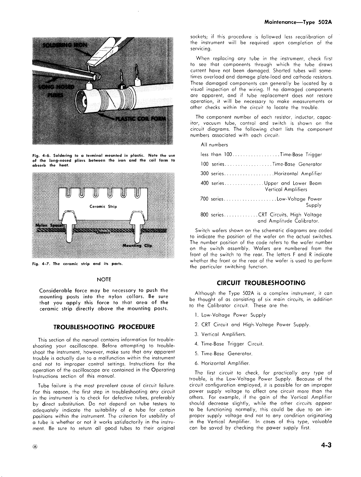
Fig.
of
the
absorb
Fig.
4-6.
long-nosed
the
4-7.
Soldering
heat.
The
ceramic
to
pliers
a
terminal
strip
between
and
mounted
its
the
parts.
iron
in
plastic.
and
sockets;
the
instrument
Maintenance
if
this
procedure
will
is
required
followed
upon
be
less
completion
—
Type
502A
recalibration
of
of
the
servicing.
When
replacing
to
see
that
current
have
times
overload
These
damaged
visual
inspection
are
apparent,
operation,
other
itor,
circuit
numbers
Note
the
use
the
coil
form
to
The
vacuum
All
less
100
300
400
700
checks
component
diagrams.
associated
numbers
than
series
series
series
series
any
tube
components
not
and
components
of
and
it
will
within
tube,
100
through
been
damaged.
damage
plate-load
the
wiring.
if
tube
be
necessary
the
circuit
number
of
control
The
following
with
each
......................................
.....................................
.......................................
................................
...........................................
in
the
which
Shorted
can
generally
If
no
replacement
to
make
to
locate
each
resistor,
and
switch
chart
circuit:
Time-Base
Horizontal
Upper
Vertical
Low-Voltage
instrument,
the
tubes
and
cathode
be
damaged
does
measurements
the
inductor,
is
lists
Time-Base
and
Lower
Amplifiers
check
tube
will
located
components
not
trouble.
shown
on
the
component
Trigger
Generator
Amplifier
Beam
Powe
first
draws
some
resistors.
by
restore
capac
the
r
a
or
Supply
800
series
Switch
to
indicate
The
number
on
the
front
of
whether
the
particular
wafers
the
switch
the
the
position
switch
front
...........................
shown
position
of
assembly.
to
or
the
switching
on
the
CRT
and
the
of
the
the
code
Wafers
rear.
rear
function.
Circuits,
Amplitude
schematic
wafer
refers
The
of
the
on
are
letters
wafer
High
diagrams
the
to
the
numbered
F
is
Voltage
Calibrator.
are
actual
wafer
from
and
R
used
to
coded
switches.
number
indicate
perform
the
Considerable
mounting
that
you
ceramic
TROUBLESHOOTING
This
section
shooting
shoot
trouble
and
operation
Instructions
For
in
by
adequately
positions
a
ment.
Tube
this
the
direct
tube
the
is
not
failure
reason,
instrument
is
Be
posts
apply
strip
of
your
instrument,
actually
to
improper
of
the
section
is
substitution.
indicate
within
whether
sure
force
may
into
this
directly
the
manual
oscilloscope.
however,
due
to
control
oscilloscope
of
this
the
most
the
first
is
to
check
Do
the
the
instrument.
or
not
it
to
return
NOTE
be
the
force
above
contains
Before
make
a
malfunction
settings.
are
manual.
prevalent
step
in
for
not
suitability
works
all
good
necessary
nylon
collars.
to
that
the
mounting
PROCEDURE
information
attempting
sure
within
Instructions
contained
cause
troubleshooting
defective
depend
on
of
a
The
criterion
satisfactorily
tubes
area
that
in
of
tubes,
tube
to
to
tube
for
push
any
the
the
circuit
in
their
the
Be
sure
of
the
posts.
for
trouble
to
trouble
apparent
instrument
for
Operating
failure.
any
circuit
preferably
testers
for
certain
usability
the
instru
original
CIRCUIT
the
to
of
Although
be
thought
to
the
Calibrator
1.
Low-Voltage
2.
CRT
Circuit
3.
Vertical Amplifiers.
4.
Time-Base
5.
Time-Base
6.
Horizontal
The
first
trouble,
is
circuit
configuration
power
supply
others.
For
should
decrease
to
be
functioning
proper
supply
in
the
Vertical
can
be
saved
the
of
circuit
the
example,
Type
as
consisting
circuit.
Power
and
Trigger
Generator.
Amplifier.
to
Low-Voltage
employed,
voltage
slightly,
normally,
voltage
Amplifier.
by
checking
TROUBLESHOOTING
502A
is
a
of
These
Supply
High-Voltage
Circuit.
check,
for
Power
it
to
affect
if
the
gain
while
this
and
not
In
cases
the
complex
six
are
is
one
the
to
power
main
the:
Power
practically
Supply.
possible
circuit
of
the
other
could
any
of
supply
instrument,
circuits,
Supply.
Vertical
be
condition
this
in
any
Because
for
an
more
circuits
due
type,
first.
it
can
addition
type
of
the
improper
than
the
Amplifier
appear
to
an
im
originating
valuable
of
4-3

Maintenance
On
the
other
isolate
trouble
viously
for
appear
exists
exists
example,
to
in
investigated
the
be
first.
—
Type
hand,
to
in
that
when
normal,
Vertical
one
502A
the
circuit.
the
it
Amplifier
crt
particular
If
intensity
is
apparent
display
there
and
and
circuit
is
that
this
can
often
when
no
vertical
horizontal
an
circuit
open
be
used
trouble
deflection,
deflection
condition
should
to
ob
be
TROUBLESHOOTING
Proper
Oscilloscope
Power
Supply.
their
specified
calibration.
For
no
If
the
graticule
the
power
fuse,
and
234
or
248
switch.
(If
operation,
switch
may
voltage
is
power
transformer.
If
both
the
primary
mally
and
cuits.
If
only
is
zero,
the
series
regulator,
although
the
measure
voltage
trouble
For
output.
failure
the
at
can
regulate
If
any
or
voltages,
designed
and
volts),
other
cause
the
change
tive
age
it
per
the
Calibration
250
All
—
of
of
may
voltage.
instrument
rms.
nominal
one
the
150
in
a
the
be
operation
output
switch
the
your
the
correct,
the
the
one
this
first
to
volts),
or
low
volt
the
defective
—
possible
depends
The
tolerances
lamps
is
line
voltage.
volt
operation,
instrument
fan
be
open.)
graticule
circuit
of
trouble
of
the
trouble
or
trouble
To
determine
secondary
the
output
be
determined
of
the
at
the
all
of
the
check
regulate
with
(There
line
all
of
voltage
supply
regulation
150
volt
In
any
according
Procedure
will
next
is
are
to
POWER
of
every
on
proper
regulated
for
voltage
and
turned
is
run
If
the
check
lamps
the
power
lies
outputs
probably
power
can
also
which
voltage
of
regulated
correct
supplies
the
between
the
design
similar
voltages).
the
supply
power
for
point
—
150
supply
readjust
event
section
THE
SUPPLY
circuit
operation
voltages
the
instrument
the
fan
on,
check
If
your
instrument
also
check
wired
even
though
fuse
is
the
and
transformer
somewhere
of
the
Low-Voltage
due
transformer
be
circuit
of
the
rectifier.
by
voltage
voltages.
fail
line
voltage.
105
center
line
Improper
voltages
supplies
regulation,
of
volt
supply.
is
off
the
—
it
will
be
to
the
of
this
LOW-VOLTAGE
in
the
Type
of
the
Low-Voltage
must
remain
to
maintain
do
not
operate
the
power
is
wired
the
thermal
for
110,
117
or
the
thermal
not
blown
windings
operate
is
operating
the
secondary
Power
defective
secondary
by
a
The
cause
readings
supplies
at
The
125
volts
117
ranges
line
be
off.
dependent
consequently,
supplies
If
the
a
small
Control
to
and
short
is
supplies
volts
voltage
output
for
given
primary
the
fan
in
to
a
caused
element
the
transformer
power
to
regulate
and
at
voltage
to
are
and
all
the
by
only
150
necessary
procedures
manual.
502A
within
when
switch,
for
220,
cutout
124
volt
cutout
the
line
of
correctly,
nor
Supply
rectifier,
winding,
across
defective,
and
of
obtained.
the
proper
(or
(or
234
for
may
upon
is
indica
volt
amount,
the
pro
recalibrate
in
the
the
cir
the
the
to
are
210
the
the
its
Fig.
4-8.
Low
voltage
power
supply
test
a
In
case
properly,
1.
Line
voltage
2.
Transformer
3.
Output
4.
Tubes
or
5.
Loading
Important
supply
schematic
perform
of
improper
ing
of
the
the
power
put
bus
to
mately
3,500
ohms,
and
If
none
the trouble,
a
change
acitors
composing
tance
networks
V636A
and
since
they
power
supplies.
part
or
index
parts.
quick
of
the
check
voltage
transistors
power
checks
regulation
supply.
and
ground.
ohms,
the
of
the
the
in
value
the
determine
to
troubleshooting
failure
the
voltage
diagram.
on
check
4-350
cause
in
base
Use
The
of
following:
of
the
supply
the
power
by
To
check
the
The
—
the
+
volt
preceding
of
of
one
the
voltage
the
grid
circuits
the
resistance
following
a
single
rectifier
voltages
These
supply
a
power
power
resistance
150
volts
100
bus
checks
the
improper
or
more
circuits
of
output
checks
information
the
points.
power
supply
are
marked
voltages
operation.
supply
is
supply
of
the
power
bus
should
volt
bus
approximately
approximately
determine
regulation
of
the
divider
networks.
of
V746B,
Q644
are
particularly
voltage
of
to
isolate
Low-Voltage
may
on
may
incorrect
loading,
read
10,000
resistors
their
be
Power
to
the
be
One
supply
the
is
The
V666B
respective
the
used
regulate
power
used
cause
load
shut
out
approxi
4,000
ohms.
cause
probably
or
cap
resis
and
critical
defective
as
Supply.
off
to
of
a
4-4

If
the
output
voltage
check:
1.
For
high
line
2.
The
Q644,
3.
For
If
and
insufficient
the
amplifier
output
Q634)
check:
1.
For
proper
resistance
R753;
R671
and
R673;
R649)
If
the
output
voltage
check:
1.
For
low
line
voltage
2.
The
series
regulator
V677,
V637,
or
Q647)
3.
For
4.
Open
5.
Rectifiers
If
the
1.
The
2.
The
If
the
excessive
output
resistance
capacitors
output
or
leaky
(V722,
voltage
voltage
check:
1.
Filter
capacitors
the
regulated output
2.
AC
bypass
capacitors
amplifiers
3.
Regulator
amplifiers
TROUBLESHOOTING
For
troubles
The
crt
display
voltage
troubles
produce
If
no
available
fective
the
cause.
a
neon
glows,
to
be in
voltage,
is
abnormally
would
simultaneously
If
the
operating.
the
regulator
intensity,
the
depend
power
occurring
similar
high
from
oscillator
The
bulb
oscillator
the
or
in
neon
If
which
calibration,
supply
effects
voltage
either
circuit
oscillator
against
secondary
the
regulator
low.
bulb
replacement
tube
voltage
tubes
loading
voltage
loading
filter
V652,
values
across
at
on
in
the
on
the
or
V800,
is
It
is
be
does
V814
is
high
and
transistors
is
high
values
R621, R622,
is
low
tubes
and
capacitors
V602,
is
low
with
in
the
the
is
normal
the
output
in
the
(screen
THE
affect
focus,
the
proper
in
the
high-voltage
both
beams.
(or
insufficient
grid
or
excessive
can
be
the
oscillator
operating
windings
unlikely
does
circuit
defective.
not
of
the
not
of
glow,
with
with
in
the
and
with
transistor
or
D642A,B)
normal
dividers
dividers
with
of
grid
circuits
grid
both
and
operation
CRT
cathode
quickly
and
T801
(V814),
that
all
oscillator
clear
(V746,
dividers
R623;
the
circuits)
CRT
beams
Circuit.
power
loading
checked
the
three
the
up
excessive
V666,
normal
and
excessive
(V747,
ripple,
excessive
rectifiers
of
the
CIRCUIT
geometry
of
In
supply
high
voltage)
supplies,
is
tube.
trouble
if
there
if
the
high
rectifier
oscillator
tube
the
trouble,
ripple,
ripple,
(R751
R648
ripple,
check:
ripple,
and
regulator
of
the
general,
probably
by
placing
If
the
is
is
no
voltage
V800
V636,
and
and
V757,
the
high-
will
a
de
bulb
likely
high
tubes
is
not
and
check
Maintenance
—
Type
502A
Fig.
4-9.
Checking
by
means
the
components
and
secondary
If
the
proper
one
of
not
components
proper
plies
voltage
beams.
be
distorted
or
by
sensitivity,
If
setting
justed
Calibration
caused
by
measurements.
at
is
the
be
checked.
output
and
dividers
If
the
crt
displays
a
loose
If
the
high
decreased
this
tube
of
if
necessary
For
troubles
Troubles
by
the
Astigmatism
(except
for
place
the
TROUBLESHOOTING
For
no
If
a
trace
plates
are
of
a
neon
of
windings
high
voltage
associated
voltages
the
circuit
which
these
itself
or
connection
voltage
or
the
regulator
or
any
the
HV
Procedure
which
which
defects
the
crt)
If
crt.
spot
or
(or
spot)
externally
operation
output
In
increased
bulb.
the
oscillator
of
this
case,
with
are
is
still
control
are
also
its
cathode
can
be
at
appears
component
Control
according
section
affect
in
the
Controls,
can
be
the
circuit
AMPLIFIERS
trace
is
shorted
of
transformer
voltage
supplies,
the
obtained
not
normal,
caused
the
neck
horizontal
circuit
(R826)
affect
only
intensity
checked
visible
the
high
circuit
is
the
you
can
inoperative
operating
the
intensity
circuitry.
by
of
to
be
(V814)
of
this
should
to
the
of
this
only
one
and
or
by
by
checks
THE
when
together,
voltage
including
T801.
obtained
oscillator
check
from
correctly,
the
trouble
Badly
an
open
the
crt.
abnormal,
and
should
circuit
be
procedure
manual.
one
beam
focus
the
voltage
out
VERTICAL
the
but
oscillator
the
from
circuit
the
rectifier
supply.
all
the
H.V.
check
and
focus
will
misfocused
Geom
as
evidenced
vertical
deflection
be
checked.
is
changed,
checked
will
crt.
satisfactorily,
vertical
given
beam
generally
voltage
These
and
resistance
deflection
disappears
dividers,
circuit
primary
at
least
need
and
If
sup
of
likely
and
Control
and
ad
in
parts
when
the
the
the
the
the
re
be
4-5

Maintenance
the
short
is
unbalance.
the
If
the
the
with
which
check
SELECTOR
Fig.
plifier
If
stage
and
lies
circuit
move
ponding
short
on
readjust
plates
of
trace
output
an
ohmmeter
side
particularly
4-10.
by
shorting
the
trace
are
the
crt
somewhere
of
the
points
between
the
screen
the
Checking
the
shorting
—
removed,
To
determine
the
does
stage
is
open.
switch,
does
shorted
pin
output
on
the
as
DC
Type
502A
the
output
not
appear,
and
is
On
the
connections
SW489.
for
unbalance
the
vertical
appear
together,
connections
in
the
stage.
strap
opposite
points,
each
connection
BAL
controls
vertical
the
stage
the
crt,
perhaps
the
vertical
back,
amplifier
cause
(V474B
one
side
is
the best
upper
in
deflection
when
the
is
normal.
amplifier
To
locate
point
sides
in
turn,
is
when
of
of
open.
beam
at
the
the
upper
plates
the
circuit
by
of
the
made.
shorting
this
and
the
A
way
plates
between
ahead
the
point,
the
spot
is
in
a
condition,
V484B)
circuit,
continuity
vertical
HORIZ
beam
together.
The
defective
between
circuit.
You
between
state
to
DEF
vertical
of
the
trouble
of
should
may
of
short
together.
between
check
determine
amplifier,
PLATE
am
output
this
point
then
the
plate
stage,
corres
As
you
return
have
grids
d
c
the
input
stage.
When
you
reach
a
point
where
the
spot
does
not
return
to
the
screen,
the
stage
immediately
this
point
is
at
fault.
The
trouble
may
be
fective
tube,
resistor,
or
capacitor.
caused
following
by
a
de
For
to
of
Insufficient
gain
characteristics
is
small,
for
gain.
If
the
no
vertical
first.
Then
of
both
plifier.
amplifier
mon
to
Insufficient
upper
or
For
waveform
Waveform
gories
. . .
wave
is
distortion
waveform.
the
leading
wave
while
mid-portion
Waveforms
types
of
The
shape
the
cause
wave.
A
mal
for
very
and
a
nominal
at
the
upper
when
this
range
of
the
Refer
change
sides
Such
stages,
both
lower
applied
can
high
of
of
nominal
the
insufficient
vertical
Vertical
to
in
deflection
check
of
the
parts
or
sides
vertical
frequency
distortion
low
frequency
to
be
High
edge
low
frequency
of
the
showing
frequency
these
the
distortion
low
input
amount
frequency
distortion
instrument
or
no
deflection
of
the
Amplifier
the
Calibration
gain
is
at
all,
for
components
amplifier
are
common
plate
dropping
of
the
deflection
distortion
can
an
input
determined
frequency
and
trailing
waveform.
low
distortion
waveforms
amount
frequencies
of
high
limits
is
excessive
that
vertical
Vertical
more
the
without
amplifier.
limit
of
be
and
high
of
the
by
distortion
edge
distortion
frequency
will
and
the
of
low
frequency
of
it
constitutes
deflection.
indicates
Amplifier.
can
usually
Procedure
pronounced,
tubes
which
unbalancing
cathode
resistors
will
also
the
amplifier
divided
frequency.
oscilloscope,
the
shape
will
of
will
are
shown
vary
widely
frequency
frequency
when
the
instrument.
in
the
a
change
be
for
should
will
affect
resistors
which
be
into
of
primarily
the
applied
primarily
distortion
in
of
distortion
ac
coupling
distortion
normal
a
trouble.
If
the
change
recalibrated
this.
or
if
there
be
checked
the
the
are
caused
is
exceeded.
two
If
a
square
the
type
the
displayed
square
affect
and
figure
however,
the
applied
is
is
normal
It
is
frequency
in
in
com
if
cate
affect
4-11.
is
used,
the
gain
am
the
the
the
two
with
nor
only
is
of
Fig.
of
the
form.
4-6
4-11.
the
waveform,
waveform,
Frequency
(c)
(b)
High
distortion,
High
frequency
(
a)
frequency
distortion
Low
distortion
frequency
of
a
of
distortion
a
1200
1200
cycle
cycle
square
of
square
a
wave
20
cycle
square
wave
due
to
wave
due
due
to
to
excessive
attenuation
of
attenuation
boost
the
of
of
the
high frequency
the
high
low
frequency
frequency
components
components
components
of
the
wave-
of

Low
frequency
in
the
time
become
gassy,
time
constant
response
an
high
adjustment.
compensation
high
related
the
can
face.
the
completely
justment
circuits.
For
pickoff
cathode
circuit.
High
frequency
improperly
frequency
frequency
to
An
overshoot
result
be
caused
If
this
tubes
improper
Improper
circuit.
follower,
and
of
the
of
in
correct
triggering
distortion
constant
their
network
the
circuit.
response
adjusted
distortion
Refer
procedure.
response
high
waveform
excessive
by
a
type
of
the
amplifier.
the
operation
triggering
The
V493
of
resultant
to
freqeuency
tube
distortion
trouble,
can
trouble
TROUBLESHOOTING
If
the
trouble
occurs
in
TRIGGER
defective
If
SELECTOR
trigger
tubes
GERING
AUTOMATIC
should
the
appear,
multivibrator
made
in
plate,
+
plifier
in
ING
monitoring
the
All
20,000
To
A
96
the
If
trigger
the
SELECTOR
TRIGGER
trouble
switch,
multivitbrator
V24
and
voltages
ohms-per-volt
determine
LEVEL
apear
either
check
as
follows:
AUTOMATIC
pin
6,
volts.
circuit
resistors
the
voltage
LEVEL
the
switch,
SELECTOR
occurs
either
V45.
in
this
which
Control
position.
multivibrator
may
on
of
If
Control
on
the
the
V24B.
the
is
defective.
or
voltage
the
trigger
be
trigger
With
voltage
switches
measured
will
crt.
at
position,
This
completely
is
the
input
which
can
probe.
you
the
Operating
Other
of
the
shown
high
condition
of
the
be
may
or
by
THE
some
in
all
the
be
NOTE
section
voltmeter.
stage
fully
With
If
is
input
fault.
input
the
TRIGGERING
voltage
is
The
of
is
at
pin
usually
coupling
grid
current
will
affect
be
affected
Consequently,
should
first
factors
vertical
compensation
accentuated
frequency
known
is
detected,
If
tube
replacement
you
should
high
frequency
caused
by
be
caused
a
defective
TIME-BASE
but not
the
trouble
switch
or
positions
trigger
is
no
defective.
incorrect,
6
input
at
fault.
are
defective,
counter-clockwise
triggering
the
sweep
amplifier
amplifier
measure
should
trouble
the
circuit.
correct,
through
of
V24B.
caused
by
circuit.
will
the
low
considerably
in
any
check the
Instructions
which
can
amplifier
compensation.
in
as
cathode
you
should
then
check
compensation
a
defective
either
component
networks.
all
positions
is
likely
input
coupling
of
the
amplifier
You
should
measured
If
the
the
rotate
rotate
signal,
does
the
or
circuit
LEVEL
voltage
be
approximately
trigger
will
probably
the
its
The
voltage
not
sweep
range
a
change
If
tubes
establish
are
Fig.
by
frequency
case
probe
for
the
affect
the
mainly
4-11
This
inter
check
does
not
the
ad
trigger
a
faulty
in
the
TRIGGER
of
the
due
to
circuit.
TRIGGER
or
the
check
with
a
the
TRIG
to
the
the
sweep
appear,
does
the
trigger
may
Control
still
at
the
input
am
exist
TRIGGER
while
should
by
be
Maintenance
vary
a
of
is
a
between
voltage
TRIGGERING
the
trouble
in
the
sistors.
V45A
For
free-running
If
the
ING
LEVEL
positions
multivibrator.
resistors
or
R111
R143).
For
no
If
the
waveform
RECURRENT
output
of
this
age
of
will
probably
mately
the
Miller
reading
being
will
depend
The
two
rately
Miller
If
the
is
high,
of
the
conduct,
(3)
Hold-Off
Gating
not
drive
can
ments.
will
Check
reading
are
probably
a
possible
tive
Check
Measure
ator
volts,
to
be
the
stage
be
checked.
be
indicate
than
(pin
range
will
multivibrator
The
voltage
and
the
approximately
indicates
LEVEL
be
grid
of
a
Control.
in
the
will
probably
divider
V45B
defective
trigger
TROUBLESHOOTING
GENERATOR
operation
Time-Base
this
in
)
or in
horizontal
Time-Base
to
remain
trouble
the
+
30
stage
of
allowed
conditions
in
the
Stage
voltage
the
following
(2)
Multivibrator
the
detected
When
the
is
—
V152
3 of
the
Runup
operating
is
Control
is
due
This
trouble
the
grid
the
when
the
position,
at
can
Miller
tube,
be
either
volts.
has
+30
volts
to
runup.
on
the
following
is
at
tube
is
conditions:
Sweep-Gating
Cathode
Hold-Off
by
an
improper
the
defective
votage
only
a
few
conducting
cause
of
50
volts,
and
resistors
the
voltage
V
1
61
Cathode
correctly.
defective
Generator
is
not
in
to
astable
will
circuit
grid
circuit
sweep
Generator
TRIGGERING
some
defect
some
fixed
be
obtained
V161A. The
approximately
A
reading
run
up
indicates
The
type
of
of
plate
paragraphs.
Run-up
the
plate
cutoff.
Followers
and
(4)
Cathode
a
series
at
the
volts
normally
the
trouble.
however,
R147
at
the
B).
If
this
Follower
and
its
the
of
and
voltage
stage.
negative,
If
34
and
trigger
If
the
voltage
multivibrator.
be
network
is
particularly
THE
free
runs
RECURRENT
operation
probably
V135A
of
V145A
is
not
LEVEL
in
the
voltage.
by
measuring
voltage
of
+300
has
not
that
condition
trouble
occurring
voltage
of
the
This
can
(1)
Disconnect
Multivibrator
do
Runup
Cathode
Follower.
of
systematic
reading
grid
of
the
and
If
the
the
diodes
and
output
of
voltage
stage
this
voltage
grid
and
—
135
volts.
input
range
due
to
between
producing
+300
the
will
not
the
R148.
is
cathode
critical.
TIME-BASE
when
the
or
of
the
be
due
(resistors
(resistors
Control
circuit
A
clue
the
reading
volts
volts
been
Miller
that
actually
be
handled
Miller
result
from
Diodes
does
reset
Follower
The
defective
voltage
is
obtained,
Miller
Disconnect
can
be
voltage
are
not
the
Time-Base
approximately
may
is
low,
circuits
Type
502A
An
incorrect
amplifier
is
correct,
A
trouble
defective
the
plate
TRIGGER
AUTOMATIC
sweep
gating
to
defective
R185,
R186,
R141
a
sawtooth
is
in
is
causing
to
the
cause
plate
volt
obtained
or
approxi
indicates
reset,
in
tube,
eliminated
is
while
stage
is
exists
the
circuit.
sepa
V161A,
any
do
not
reset,
the
Sweep-
stage
measure
tube.
If
Diodes
more
nega
conducting.
Gener
+250
be
assumed
however,
should
that
one
does
re
the
the
not
not
this
the
or
of
or
a
as
4-7

Maintenance
Next,
measure
Off
Cathode
readings
followers
voltages
the
at
multivibrator
and
lie
V135B,
of
Miller
that
allowed
trouble
the
trouble
trouble
Multivibrator
voltage
STABILITY
the
vibrator
does
stage.
remains
is
causing
this
condition
does
the
For
current
constant.
defective
If
Miller
cause.
For
screen,
Hold-Off
before
adjusted
R176,
be
resistors
If
the
the
grid of
the
in
that
and
V135B.
Low
voltage
the
exists
trouble
is
To
check
voltmeter.
not
If
the
rotated,
point.
not
grid
nonlinear
A
nonlinear
the
nonlinearity
tube
insufficient
If
the
the
the
checked.
should
are
are
previous
multivibrator
stage.
Stage
tube
to
exists
ot
and
switch,
voltage
relatively
the
is
adjust
circuit
charging
If
Miller
horizontal
but
circuit
to
resistance
—
Type
Follower,
operating
incorrect,
in
the
(more
V145A,
at
is
perform
on
is
likely
on
probably
stage.
the
the
junction
ADJUST
With
the
a
defect
stage
If
such
a
to
of
the
or
a
does
sweep
normal
502A
the
grid
V183A
be
approximately
correctly.
check
cathode
checks
gave
V135A
should
positive
still
Check
the
and
the
will
not
the
plate
conducting
its
normal
only
a
few
to
be an
all
ranges
due
Sweep-Gating
of
Control
this
voltage,
sweep
should
check
the
at
the
junction
constant
shorted
sweep
nonlinearity
tube
is
as
in
cathode
to
effectively
is
the
holdoff
the
proper
V135A.
sweep
voltage
the
Timing
is
the
occurs
leaky
Timing
horizontal
trace
starts
not
extend
resetting
is
complete.
length
in
the
to
cathode
the
circuits
than
does
voltages
resistors
Run-up
of
quite
ranges
of
to
R114
for
free
resistances
of
the
case,
Capacitor
exists
probable
only
to
the
with
cathode
voltage
and
V145B.
—
4
volts
If
either
hold-off
of
the
correct
results,
be
sufficient
—
35
not
open
a
a
the
level,
at
at
Sweep-Gating
volts).
reset,
at
the
in
the
the
Miller
heavily
runup
operation.
of
the
timing
the
TIME/CM
defective
Multivibrator,
and
R1
16
reading
the
Sweep-Gating
run.
If
which
resistors
STABILITY
follower
regulate
probable
capacitor.
check
will
be
at all
cause
certain
Capacitor
deflection
the
left-hand
the
right-hand
If
the
SWP
circuit
sweep
the
of
the
Both
if
the
or
both
capacitor
two
stages.
the
to
If
this
the
trouble
plates
of
cathode
tube
and
is
not
TIME/CM
resistor.
switch,
Sweep-Gating
monitor
and adjust
of
—
70
the
multivibrator
make
R1
14
ADJUST
V145B
the
voltage
cause
If
the
the
resistors
generated
does
not
sweep
of
the
sweep
is
the
side
Multivibrator
cannot
LENGTH
of
V161B
Hold-
of
these
cathode
of
these
voltage
reset
is
must
V135A,
circuit
indicates
being
If
switch
If
volts
Multi
up
and
R116
Control
may
of
voltage
if
remain
rates,
trouble.
rates,
probable
of
side,
Control
should
and
the
this
the
the
the
this
so,
the
the
on
be
the
the
the
the
be
Single
at
in
a
If
D126
normally
However,
operation,
sweep.
produce
then
even
all
should
+
sweep,
ducing
be
circuit
to
Base
negative.
or
when
This
another
If
on
the
the
though
right.
be
138
volts
however
a
approximately
D124
being
not
operate
When
D124
Generator
no
effect
TROUBLESHOOTING
For
no
If
both
plates
are
the
short
of
unbalance.
zontal
Amplifier
previously
unbalance.
Horizontal
together
return
this
resistors
For
trace
crt
be
change
be
voltage
to
more
components
of
be
resistances
be
to
the
point
in
insufficient
If
the
will
screen.
calibrated
in
possible
and
the
instructions
If
the
pronounced,
the
amplifier.
checked
checked.
until
Sweep
will
opens,
the
the
when
the
the
circuit
of
course
sweep
other
Time-Base
the
Single
If
this
condition
checked.
when
the
when
sweep
the
+4
opened
to
lockout,
normally.
is
shorted
to
The
TRIGGERING
upon
spot
or
beams
are
externally
is
removed,
The
is
for
troubleshooting
Corresponding
Amplifier
a
point
face
of
is
the
one
the
cathode
gain
of
not
extend
In
addition,
on
any
sweep
timing
to
correct
the
X
decrease
which
in
in
or
The
as
one
the
not
Time-Base
MODE
instrument
will
means
across
hand
Generator
sweep
It
should
Time-Base
the
plate
volts.
will
even
free-run
the
free-running
AMPLIFIER
trace
visible
shorted
the
procedure
somewhat
circuit
is
reached
the
crt.
which
and
or
no
the
Horizontal
to
the
range
and
this
1
CAL
contained
gain
if
there
will
affect
input
of
the
cathodes
perform
Generator
switch
is
is
not
lockout
that
the
D126
becomes
will
circuit
exists
the
normally
Time-Base
voltage
also
though
or
leaky
since
the
LEVEL
THE
when
together,
horizontal
for
the
the
points
on
should
The
stage
is
plate
horizontal
the
left
sweep
of
the
sweep
trouble
and
X20
in
the
of
the
is
the
cathode
first
of
the
properly
will
in
the
NORMAL
set
up
for
at
each
incoming
crt.
shorted
not
produce
seems
plate
voltage
be
Generator
cause
the
troubleshooting
same
be
where
defective.
circuits.
Amplifier
no
gain
steps.
Generator
of
V135A
the
the
READY
it
will
cause
grid
of
Control
Time-Base
HORIZONTAL
horizontal
but
amplifier
as
Vertical
opposite
progressively
the
immediately
Check
deflection
and
right
timing
TIME/CM
length
by
adjusting
CAL
Controls
Calibration
Horizontal
sweep
at
but
follower,
Also,
amplifier
still
operate
position.
Single
the
end
trigger
or
a
to be
V135A
disappear
is
not
resetting
of
approximately
is
producing
is
not
will
normally
Single
light
the
is
will
have
Generator.
deflection
is
in
a
the
that
explained
Amplifiers
sides
shorted
beams
do
following
for
decreases,
sides
will
no
switch.
slight,
the
according
Procedure.
Amplifier
all,
check
the
balance
V
1
83B,
the
common
stages
Sweep
of
the
will
leaky,
sweep
V135A
pro
Sweep
seems
Time-
pulled
little
when
state
Hori
for
of
the
not
open
the
of
the
longer
If
the
it
may
high
for
should
should
a
is
4-8

SECTION
CALIBRATION
PROCEDURE
5
General
The
but
and
tion
tenance.
Apparent
actually
circuits.
used
troubleshooting
in
instrument.
required
adjustments.
given.
they
instructions
equipment,
are
are
remain
tions
signal
steps
make
mentioned
adjustments
adjustments
amplifier
should
supply
entire
are
the
instrument
occasional
other
is
desirable
the
Consequently
in
conjunction
In
the
instructions
the
proper
to
In
each
Controls
were
disconnected
given
connected
are
is
applied
It
will
be
immediately
to
determine
be
or
instrument
If
you
find
not
aware
difficulty,
Information
components
calibration
given
in
in
adjustments
calibrated.
the
Equipment
The
following
a
complete
1.
with
volts
accurate;
curacy,
DC
voltmeter
corrected
and
particularly
few
within
should
adjustments
from
troubles
result
work.
sequence
Each
numbered
make
are
in
during
are
given
except
at
to
the
to
to
to
necessary
that
in
the
these
high
must
that
of
it
is
usually
Required
equipment
calibration
(sensitivity
readings
3%
portable
not
are
the
occurring
of
improper
this
with
that
for
one
adjustment
step
assumed
the
to
for
input
the
end
contrary.
the
disconnect
the
same
for
preceding
the
proper
step.
horizontal
circuits
are
In
voltage
be
a
circuit
which
of
within
for
test
after
require
will
changed.
standpoint
in
section
the
Maintenance
follow,
a
complete
step
only
to
previous
change
signal
of
each
Input
instrument
them
input
you
the
settings
Due
to
and
usually
required,
addition,
power
calibrated.
is
out
particular
best
to
or
its
the
Type
of
at
2900
volts.
meters
a
period
frequent
be
necessary
Also,
of
the
instrument
calibration
of
the
the
contains
or
the
required
be
set
step
their
sources,
step
signal
until
or
connector.
to
refer
adjustment
the
vertical
cannot
the
if
either
supply
of
calibration,
adjustment
calibrate
equivalent
502A
least
1%
for
Be
have
of
use.
recalibration,
a
periodic
preventive
of
one
manual
section
steps
are
calibration
the
a
series
information
at
the
unless
settings.
and
unless
voltages
specific
until
another
to
the
you
for
the
interaction
amplifiers,
be
made.
entire
the
is
adjusted,
the
entire
is
necessary
Oscilloscope.
5000
ohms
100,
150
sure
your
the
required
when
tubes
calibra
main
are
often
or
more
should
during
arranged
of
information
of
related
positions
specific
All
all
jumpers
instructions
should
instruc
input
calibration
wish
controls
between
single
When
amplifier
—
150
but
will
correct
circuit.
per
and
meter
the
test
not
volt
the
you
volt)
350
ac
for
be
Fig.
5-1.
Tools
required
for
calibrating
is
2.
to
is
Accurate
or
0-300
3.
Variable
500
watts.
4.
Time-mark
neither
to
substitute
microsecond,
100
microsecond,
5.
Square-wave
105
necessary
following
1
kilocycle,
20
nanoseconds,
approximately
6.
Oscilloscope,
or
317
substitute
(1)
calibrated
volts
7.
50-ohm,
8.
Tektronix
9.
Tektronix
10.
Tektronix
Tektronix
11.
Tektronix
12.
Coaxial
rms-reading
volts
for
autotransformer,
generator,
of
these
a
5
microsecond,
Square-Wave
to
substitute
specifications:
and
40
Oscilloscope
an
oscilloscope
vertical
per
division
42
50-ohm
Type
47 pf
part
Type
"T"
210-
instruments
time-mark
and
1
generator,
Generator
10
kilocycles,
and
(3)
millivolts
Tektronix
is
not
and
(2)
inch
Coaxial
Termination
5XT,
Input
number
10XT,
Connector.
to
millisecond
a
(1)
output
deflection
bandpass
50-ohm
Time
50-ohm
the
ac
voltmeter,
250-volt
having
Tektronix
is
generator
square-wave
output
Type
available,
with
011-030
available,
10
microsecond,
Tektronix
is
not
frequencies
(2)
amplitude
and
approximately
316
the
Cable
T-Pad.
Constant
T-Pad.
(1)
factors
of
Resistor.
(1).
Type
502A
0-150
operation).
a
rating
Type
180A
it
will
having
intervals.
Type
available,
generator
rise-time
variable
or
317.
it
will
following
from
d
c
to
(1)
(2)
Standardizer,
(1)
Oscilloscope.
volts
of
at
or
be
necessary
markers
50
microsecond,
105.
If
it
with
of
200
no
more
between
100
If
a
Type
be
necessary
specifications:
.01
10
megacycles.
(2)
(0-250
least
181.
at
a
Type
will
cycles,
volts.
to
be
the
than
316
10
If
1
to
5-1

Calibration
13.
Coaxial
14.
Jumpers,
15.
A
constant
frequencies
kilocycles,
should
μ
volts
If
cover
proper
When
amplitude
to monitor
oscilloscope
kept
By
signal
may
tivity
the
at
a
plitude
also
to
2
a
constant
the
frequencies
using
at
a
the
use
going
be
reduced
ranges,
sine-wave
high
amplitude
of
signal
400
feature
constant
Preliminary
Procedure
"Straight"
6
inch
amplitude
of
1
kilocycle,
kilocycles
have
volts.
amplitude
above
a
generator
the
output
the
output
of
from
to
while
generator
out
—
Connector.
with
a
variable
ranges,
and
the
amplitude.
a
DB
the
sine-wave
the
at
the
to
enable
of
the
Type
banana
sine-wave
50
and
generator
any
output
which
test
of
the
signal
box
proper
same
to
the
sine-wave
502A
(1)
plugs.
generator
kilocycles,
1
megacycle.
output
generator
amplitudes
does
oscilloscope
generator.
from
the
or
an
attenuator
generator
amplitude
time
test
oscilloscope
monitoring
(3)
100
amplitude
is
not
which
not
have
should
By
generator
to
for
the
signal
for
generator.
having
kilocycles,
The
generator
from
available
may
be
a
be
use
system,
the
Type
the
high
going
may
a
constant
output
200
500
has
used.
constant
used
of
may
502A
sensi
from
be
kept
am
the
the
be
the
NOMINAL
SUPPLY
to
-150V
100
V
350V
Connect
put
ILLUM
autotransformer
Allow
proceeding
bration,
ment
tain
supply
of
the
and
the
Do
not
supply
you
tion
the
the
autotransformer.
control
instrument
periodically
adjust
voltage
regulation
reset
voltages
are
of
the
power
clockwise
for
with
the
the
at
is
the
planning
instrument.
RESISTANCES
POWER
SUPPLIES
cord
and
Rotate
to
the
an
output
to
warm
calibration
check
the
autotransformer
117
or
234
being
are
to
—
checked.
CAUTION
150
control
actually
perform
APPROX.
the
ac
the
ON
of
117
up
for
adjustments.
input
volts
out
a
OF
GROUND
voltmeter
POWER
position
volts
several
voltage
as
necessary
except
unless
of
complete
RESISTANCE
3.5
k
4
k
10k
to
AND
and
adjust
(or
234
minutes
During
to
the
when
the
the
power
tolerance
calibra
the
to
TO
out
SCALE
volts).
before
cali
instru
main
power
or
the
Preset
as
follows:
POWER
INTENSITY
INTENSITY
FOCUS
TRIGGERING
TRIGGER
MODE
TIME/CM
VARIABLE
HORIZONTAL
HORIZONTAL
AMPLITUDE
HORIZ
SELECTOR
The
following
Input
SENSITIVITY
VARIABLE
DC
VERTICAL
the
BAL.
front-panel
AND
(both
SELECTOR
Switch
DEF
Selector
POSITION
SCALE
BALANCE
beams)
LEVEL
DISPLAY
POSITION
CALIBRATOR
PLATE
applies
to
controls
ILLUM
both
full
vertical
control
of
the
Type
counterclockwise
+
LOWER
CALIBRATED
2
EXT
VOLTS/CM
TIME
BASE
amplifiers:
.2
VOLTS
CALIBRATED
will
be
502A
PWR
OFF
midrange
midrange
midrange
AC
NORMAL
1 mSEC
midrange
OFF
AMP
A-DC
PER
CM
set
later.
midrange
1.
Low-Volfage
Connect
power
supply.
Fig.
5-2.
Set
Check
that
supplies
reset
voltages
If
125
tion
must
either
Vary
volts
of
are
the
the
are
the
the
regulate
(or
the
—
d
Power
the
the
within
+
100
150
within
output
between
low
within
c
voltmeter
—
150
outputs
or
control
of
voltage
Power
supply
Control
of
the
the
specified
+3
50
volt
slightly
tolerances.
the
autotransformer
210
and
power
+
or
—
Supply
to
the
output
for
—
supplies
250
supplies.
3%
6.2,
of
output
test
a
+
until
volts)
reading
+
100
or
are
to
their
of
points
—
out
all
between
check
The
correct
the
are
of
and
3%
power
power
—
150
shown
—
150
+
350
tolerances.
of
tolerance,
105
the
regula
supplies
voltages.
volt
volts.
volt
supply
and
in
Before
of
the
tances
5-2
power
of
applying
the
supplies
supplies
power
should
may
to
the
instrument
be
checked.
be
found
the
resistances
The
typical
in
the
chart
below.
resis
Fig.
5-2.
Power
Supply
voltage
test
points.
®2

Calibration
Procedure
—
Type
502A
Using
the
output
is
adjusted
voltage
amount
should
high
Supply
-6.2V
-150V
+
+350V
2.
R879,
Connect
the
reading
TUDE
ing
of
the
of
for
from
of
ripple
remain
line
voltage.
100V
CAL
the
cathode
of
of
+50
CALIBRATOR
22.5
to
test
each
117
105
about
TYPICAL
d
27.5
on
c
V873B.
volts
oscilloscope,
power
supply
volts.
Swing
volts
to
the
test
the
same
Return
the
RIPPLE
Typical
8mv
8mv
8mv
25mv
AMPL
voltmeter
See
on
the
switch
volts
on
check
the
125
volts
scope.
amplitude
line
voltage
AMPLITUDES
Ripple
at
105
+
50%
+
50%
+
50%
to
the
Fig.
d
c
voltmeter.
to
5
m
the
d
the
when
V
ripple
the
autotransformer
while
The
power
from
to
and
1
15V
at
105
and
at
105
and
at
105
junction
5-3.
Adjust
and
check
c
voltmeter.
voltage
125V
R885
the
output
ripple
line
AMPLI
a
and
for
read
autotransformer
observing
supply
low
117
volts.
125V
125V
and
of
R879,
Turn
for
the
at
to
graticule,
near
runs
4.
connected
Adjust
the
ground.
volts.
DISPLAY
spots
spot,
105
as
a
to
NORMAL
5.
traces
the
Control
the
then
the
bottom
parallel
HV
Remove
R833
center
Now
connect
Adjust
Replace
To
check
switch
onto
decrease
volts.
the
line
117
volts
INTENSITY
Increase
Turn
two
halo
have
the
around
until
traces.
tighten
of
to
the
the
right
to
the
until
a
arm
to
the
the
HV
HV
to
the
screen.
the
The
spots
voltage
and
position.
the
INTENSITY
a
halo
each
the
brightness
INTENSITY
The
the
the
clamp,
horizontal
side
H
center
arm
reading
ground.
voltmeter
HV
Control
shield.
regulation
2 EXT
Now
line
voltage
should
was
decreased.
the
HORIZONTAL
BALANCE
forming
trace
down
intensities
clamp.
Now
rotate
lines
V
shield
of
R833
of
+100
from
the
for
place
VOLTS/CM.
while
with
not
have
Control
Control
around
adjust
the
of
the
halos
to
the
normal
should
with
the
crt
of
the
and
with
(HORIZ
volts
H
V
a
reading
the
Position
observing
the
autotransformer
shown
Return
DISPLAY
to
the
them.
INTENSITY
is
level
still
be
the
red
until
the
graticule.
a
d
c
voltmeter
SENS
is
obtained
TEST
POINT
of
HORIZONTAL
the
the
any
blooming
the
line
switch
point
where
While
observing
BALANCE
the
same.
and
about
the
knob,
trace
BAL).
from
—
2900
focused
focused
voltage
to
the
the
observe
same.
to
to
Fig.
5-3.
Location
3.
CRT
Alignment
Turn
the
TRIGGERING
TAL
DISPLAY
ITY
Control
adjust
the
ASTIGMATISM
Position
graticule
clamp
Vertical
one
of
near
at
the
switch
until
base
of
for
the
the
a
the
Amplitude
to
NORMAL
trace
Positioning
sharpest
traces
vertical
of
the
LEVEL
is
under
crt
visible
trace
center
Calibrator
to
control).
a
and
and
test
RECURRENT,
turn
horizontal
(it
may
Adjust
(narrowest
of
the
push
the
point.
up
be
division
crt.
crt
HORIZON
the
INTENS
necessary
FOCUS
trace
width).
Loosen
against
6.
ASTIG
UPPER,
ASTIG
LOWER
Adjustment
Place
the
FOCUS
Controls
as
FOCUS
Return
a
line
quite
spots
A
screen,
possible.
doing
1
inputs.
HORIZONTAL
position
Controls
and
so
Controls
the
HORIZONTAL
appears
shields
easy
to
are
should
the
MILLISECONDS
Position
VOLTS/CM
BEAM
onto
the
LOWER
circular
BEAM
focus.
If
voltage
It
is
7.
Connect
to
the
Control
when
GEOM
both
to
and
of
the
the
the
and
that
are
in
also
Adjust
above
rotate
fully
adjust
both
so
NOTE
instead
not
CAUTION
damage
sharp
be
the
DISPLAY
both
clockwise.
the
ASTIG
defocused
the
UPPER
that
both
DISPLAY
of
in
place.
the
focus.
kept
as
adjustment.
time
marker
two
switch
the
a
crt
traces
in
UPPER
Position
UPPER
spots
BEAM
spots
switch
spot,
phosphor
The
INTENSITY
low
as
from
so
the
and
both
and
are
and
are
to
the
possible
a
Type
that
2
EXT
LOWER
beams
ASTIG
as
nearly
LOWER
in
sharp
NORMAL.
high-
when
180A
only
the
®I
5-3

Calibration
Fig.
5-4.
waveform
Adjustment
B
Procedure
the
bowing
—
Type
502A
of
the
GEOM
control.
In
of
the
vertical
lines
has
waveform
been
reduced
A
the
GEOM
control
is
to
a
minimum
improperly
by
the
proper
set
adjustment
causing
bowing
of
the
vertical
lines.
In
of
the
GEOM
control.
vertical
portions
of
the
crt
obtain
curvature
8.
Adjusting
and
a
stable
of
HORIZ
From
the
MILLISECONDS
and
the
both
LOWER
Adjust
markers
calibration
and
Every
the
REGIS
The
X
1
Set
the
1
Input
BEAM.
B
beams
Controls, position
the
Now
of
marks.
time
INT
may
above
CAL
UPPER
MILLISECONDS
applied
BEAM
of
POSITION
the
UPPER
time
possible.
sensitivity
the
other
graticule
9.
With
markers
HORIZONTAL
display.
the
BEAM
Type
markers
input
Selector
BEAM
HORIZ
are
adjust
the
the
the
the
BAL
also
three
and
DISPLAY
of
the
adjust
vertical
CRT
1
80A
of
to
as
two
two
time
CRT
must
have
BEAM
to
markers
the
Set
HORIZ
REGIS
apply
to
the
to
B-DC
5
VOLTS
are
BEAM
near
the
beams
beams
markers
HORIZ
be
controls
X20
Input
the
A
switch
are
TRIGGERING
the
GEOM
lines
at
SENS
100
the
A
UPPER
and
PER
the
just
touching
REGIS
being
CRT
HORIZ
is
the
are
may
NOTE
SENS
checked.
to
be
readjusted
interact
CAL
Selector
and
100
input
to
displayed
LEVEL
control
the
sides
of
BAL
MICROSECONDS
input
of
the
LOWER
BEAM.
the
SENSITIVITY
CM.
until
above
same.
being
not
The
with
Switch
With
until
the
the
SENS
matched
coincide
BAL
HORIZ
the
markers
first
one
At
is
at
each
traces
Adjustments
to
the
A-DC
MICROSECONDS
of
each
position.
beam
X20
on
Control
for
the
crt.
and
the
the
markers
and
another
BAL
this
adjusted
this
Adjust
the face
minimum
and
BEAM
UPPER
switches
Vertical
of
ninth
until
point
to
each
with
BEAM
time.
other.
position.
time
reset
the
the
the
the
the
X20
CAL
for
a
display
of
one
100
marker
per
2
cm.
Now
turn
every
the
to
Switch
to
X
1
time
and adjust
marker
1
SECONDS
MICROSECONDS
the
HORIZONTAL
X
1
CAL
cm.
for
one
DISPLAY
1
time
MILLI
of
as
in
Fig.
5-5.
in
rate.
centimeter
There
After
and
X10
be
Adjustment
will
adjusted
sweep
2
ments.
X5
should
the
calibration
The
intervals.
be
this
positions
checked.
of
the
control
interaction
interaction
of
Disconnect
X20
procedure
should
the
between
control.
The
for
the
set
been
so
the
time
removed
be
has
HORIZONTAL
X20
the
that
X
1
markers.
CAL
correct
markers
and
DISPLAY
X20
the
control
magnified
occur
adjust
X2
and
switch
is
at
5-4

Calibration
Procedure
—
Type
502A
10.
NORM
Turn
the
the
HORIZONTAL
tion
the
the
NORMAL
the
both
Check
start
graticule.
of
to
that
centerline
until
11.
through
From
the
both
beams
and
check
TIME/CM
1
mSEC
2
mSEC
5
mSEC
10
mSEC
20
mSEC
50
mSEC
100
mSEC
200
mSEC
500
mSEC
1
SEC
2
SEC
5
SEC
.1
mSEC
Disconnect
12.
Fast
Turn
the
ING
LEVEL
oscilloscope
Connect
V
1
83
and
waveform.
MAG
TRIGGERING
of
the
and
start
of
of
the
are
set
Timing
5
Type
as
indicated
for
proper
Time
Sweep
TIME/CM
to
RECURRENT.
to
DC.
a
probe
adjust
This
is
REGIS
DISPLAY
upper
Rotate
adjust
the
the
sweep
graticule.
correctly.
from
seconds
180A
apply
display.
TIME
1
MILLISECONDS
1
MILLISECONDS
5
MILLISECONDS
10
MILLISECONDS
10
MILLISECONDS
50
MILLISECONDS
100
MILLISECONDS
100
MILLISECONDS
500
MILLISECONDS
1
SECONDS
1
SECONDS
5
SECONDS
100
MICROSECONDS
Markers.
Rate
Control
from
C311
just
a
LEVEL
to
switch
trace
the
under
HORIZONTAL
NORM
again
Repeat
.1
time
below.
Adjust
MARKERS
Adjustments
to
10
Set
the
the
test
for
a
flat
preliminary
RECURRENT
in
the
X20
the
vertical
DISPLAY
MAG
REGIS
lies
under
adjustments
millisecond
markers
to
for
a
1
2
1
1
2
1
1
2
1
1
2
1
1
μ
SEC
and
base
switch
on
input
oscilloscope
adjustment
and
position.
the
9
Control
centerline
switch
vertical
and
the
A
input
stable
display
DISPLAY
marker/cm
markers/cm
marker/cm
marker/cm
markers/cm
marker/cm
marker/cm
markers/cm
marker/cm
marker/cm
markers/cm
marker/cm
marker/cm
the
TRIGGER
of
the
to
pin
3
the
holdoff
of
C31
place
Posi
test
1.
so
10
of
Adjustment
chart
of
will
interact
times.
display.
TIME/CM
10
μ
20
μ
50
μ
1
μ
2
μ
5
μ
Disconnect
13.
Rotate
VOLTS/CM
Control
the
HORIZONTAL
14.
Apply
TUDE
set
in
of
2.5
for
the
switch
The
vertical
amplifier
of
below.
The
and
Apply
time
SEC
SEC
SEC
SEC
SEC
SEC
EXT
the
so
10
10
50
1
1
5
Time
HORIZ
HORIZONTAL
positions
that
Checking
5
volts
CALIBRATOR.
the
2
EXT.
cm.
Check
proper
deflection.
to
the
NORMAL
following
amplifiers.
before
the
faster
1
μ
SEC
and
therefore
TIME
FROM
MICROSECONDS
MICROSECONDS
MICROSECONDS
MICROSECONDS
MICROSECONDS
MICROSECONDS
there
to
VOLTS/CM
will
markers
MARKERS
TYPE
Markers.
AMP
and
adjust
is
no
DISPLAY
External
the
EXTERNAL
With
the
the
other
Return
position
adjustments
Complete
proceeding
to
switch
NOTE
sweep
rates
the
5
μ
SEC
have
to
both
A
180A
DC
BAL
DISPLAY
switch
the
EXT
horizontal
is
rotated.
Gain
connector
HORIZONTAL
position
positions
the
HORIZONTAL
and
apply
the
to
is
indicated
timing
be
rechecked
inputs
and
ADJUST
CHECK
Adjust
1
marker/cm
Check
markers/cm
Check
marker/cm
Adjust
1
marker/cm
Check
markers/cm
Adjust
1
marker/cm
through
HORIZ
shift
of
and
Attenuator
from
DISPLAY
check
for
of
the
display
disconnect
to
both
calibration
the
other.
adjustments
trigger
OR
C160C
for
for
C31
1
for
C160A
AMP
the
spots
the
a
deflection
DISPLAY
the
of
of
in
several
for
2
1
for
2
for
the
DC
BAL
AMPLI
switch
switch
jumper.
the
one
the
the
EXT
as
Fig.
5-6.
waveform
Adjustment
B
is
of
obtained
A.
C311.
on
the
Waveforms
test
oscilloscope.
B.
A
and
C
result
from
improper
settings
of
C311.
Capacitor
C311
C.
should
be
adjusted
so
that
5-5

Calibration
15.
Gas
With
jumpers,
TIVITY
switch
LEVEL
to
Controls,
BAL
and
than
running
16.
apply
of
the
in
1
priate
Control
Control
Now
B-DC
To
.2V/CM
Set
the
.2
the
mSEC.
turn
2
cm
check
trace.
the
the
vertical
VOLTS
A-B
Position
horizontal
for
Procedure
and
Hum
ground
at
RECURRENT
position
the
may
be
the
Input
to
B-AC.
during
for
hum,
It
should
DIFF
AMPLITUDE
calibrator
amplifier.
PER
(DIFF)
the
centerline.
minimum
.2
mVOLTS
found
The
the
observe
output
CM
DC
trace
vertical
and
trace
—
Type
Check
both
the
using
onto
in
Section
Selector
trace
switching
the
not
be
BAL
CALIBRATOR
to
both
Place
position
position.
so
that
Adjust
deflection.
502A
PER
the
the
switch
should
from
amount
more
A
the
and
Set
inputs
and
CM.
Turn
POSITION
crt.
The
Two.
from
not
have
DC
to
of
than
about
switch
and
B
SENSITIVITY
the
Input
the
TIME/CM
it
lies
behind
the
.2
set
TRIGGERING
and
use
of
A-DC to
shifted
AC.
hum
on
3
at
input
Selector
V/CM
the
SENSI
DC
BAL
the
A-AC
more
the
free
mm.
.
5V
and
connectors
Control
switch
switch
the
appro
DIFF
BAL
DC
A-DC
position
and
the
SENSITIVITY
PER
CM
of
vertical
position.
deflection.
Set
the
.2V/CM
GAIN
switch
in
the
.2
VOLTS
for
2.5
centimeters
in
at
17.
.2MV/CM
Place
position
appropriate
BAL
Control
16
and
17
18.
.2V/CM
Apply
the
vertical
the
SENSITIVITY
and
horizontal
for
until
a
.5
amplifier.
DIFF
position
minimum
both
GAIN
volt
BAL
switch
the
centerline.
adjustments
signal
from
Set
trace
vertical
the
the
in
so
are
Input
Adjust
the
.2
mVOLTS
that
it
the
deflection.
correct.
calibrator
Selector
lies
behind
.2MV/CM
Repeat
to
input
switch
PER
CM
the
Fig.
5-8.
Setting
the
.2
V/CM
GAIN
control.
In
the
DIFF
steps
procedure,
meters
of
the
vertical
.2
V/CM
deflection.
GAIN
control
is
adjusted
for
calibration
2.5
centi
NOTE
To
trigger
the
display
properly
A
of
in
the
SELECTOR
which
to
the
+
AC
is
being
calibrated.
position
set
the
TRIGGER
for
the
beam
Fig.
to
waveform
5-6
5-7.
Adjustment
A
of
the
.2
MV/CM
DIFF.
BAL.
control.
If
the
will
be
obtained.
Waveform
B
shows
a
typical
display
.2MV/CM
obtained
DIFF.
BAL.
when
control
the
is
control
slightly
is
misadjusted,
adjusted
properly.
a
waveform
similar

19.
.2MV/CM
Apply
a
A
of
the
vertical
the
.2
mVOLTS
control
for
steps
18
and
Both
of
the
in
the
B-DC
the
other
checked
20.
for
Adjusting
Set
the
SENSITIVITY
TRIGGERING
POSITION
graticule
While
its
the
should
appropriate
TIVITY
the
range,
VARIABLE
now
Control
location
center
rotating the
.5
millivolt
PER
2.5
19
until
above
position
positions
proper
LEVEL
Control,
adjust
SENSITIVITY
show
graticule
is
of
GAIN
signal
amplifier.
CM
centimeters
both
gain
of
the
of
the
attenuation.
R429,
switch
to
position
line.
VARIABLE
R429
until
no
movement
center
rotated.
R429.
from
Place
position.
of
adjustments
adjustments
Input
SENSITIVITY
VAR
to
.2
RECURRENT.
the
SENSITIVITY
the
Control
line
Refer
the
the
SENSITIVITY
Set
the
vertical
are
should
Selector
Disconnect
DC
VOLTS
trace
trace
is
when
and
the
to
figure
calibrator
.2MV/CM
deflection.
correct.
also
switch.
switch
BAL
PER
With
to
the
no
longer
rotated.
it
is
VARIABLE
5-15
be
At
jumpers.
CM
the
appropriate
Control
sitting
or
to
switch
Repeat
checked
this
should
and
vertical
through
moves
The
on
SENSI
5-17
input
GAIN
time
the
trace
the
be
for
Calibration
in
Fig.
5-9.
Location
of
C469
23.
as
Adjusting
From
described
200kc
the
A
the
waveform
nector.
the
sine-wave.
and
sine-wave
in
the
B
inputs
to
Common
generator,
Equipment
The
waveform
of
the
horizontal
and
the
R462
R462
Mode
Required
vertical
Procedure
in
whose
will
amplifier.
amplifier
—
Type
C469
Vertical
Amplifier.
Rejection
qualifications
list,
apply
be
applied
EXTERNAL
Also
Ratio
1
to
502A
volt
apply
are
both
con
of
21.
Vertical
Turn
switch
with
is
drift
22.
of
connected
display.
play
square
amplifier
square-wave
termination
wave
wave.
the
to
enough
a
convenient
After
should
High
Reset
Input
SENSITIVITY
TIME/CM
From
the
vertical.
of
wave
Now
reset
the
with
C469
is
It
will
C480,
C478
capacitors
deflecting
the
a
Adjust
3
adjust
adjusted
be
Input
.2
VOLTS
d
c
source
not
Frequency
following
Selector
Type
105
at
each
the
cm
is
should
you
are
C470,
bottom.
Input
Selector
to
the
the
proper
necessary
and
may
affect
DC
Shift
Selector
PER
voltage
the
be
more
apply
The
cable
end.
amplitude
observed
rest
calibrating.
C480
A
for
an
C469
to
CM.
of
trace
controls.
After
input.
graticule
to
the
A-DC
Now
vertically
to
move
voltage.
observe
than
about
Compensations
10
kc
square-waves
should
Adjust
the
of
on
the
on
the
graticule
and
C478
adjusting
to
A-DC
and
Line
center
optimum
as
recheck
the
adjustment
adjustment
square
and
it
about
the
1
mm.
.2
VOLTS
have
a
oscilloscope
the
Type
screen.
The
center
for
for
connect
up
the
top
line
top
the
adjustment
of
the
the
deflect
8
drift,
5
0Ω
105
the
a
and
of
others.
cm.
50
to
bottom
square
the
of
on
SENSITIVITY
the
trace
A
V.O.M.
if
any.
B-DC
PER
CM
μ
SEC
the
B
input
termination
for
a
stable
until
a
of
line
for
best
possible
bottom
cable
the
square
adjust
C469.
the
square
of
C470,
one
of
these
The
dis
the
the
and
The
one
Input
Selector
to
.2
VOLTS
erator
to
ends
with
cable
connected
tude
of
the
is
obtained
Set
the
SENSITIVITY
TAL
DISPLAY
form
should
form
adjust
from
the
opening
of
Elimination
result
in
a
loop
must
ratio.
To
check
to
100
kc.
PER
CM
and
not
exceed
It
should
between
mon
all
Mode
cables
At
brated
before
this
the
volt
of
switch
PER
the
oscilloscope
50Ω
terminations.
to
sine-wave
on
the
Input
Selector
switch
switch
now
the
end
of
the
loop.
of
rejection
be
less
the
adjustment
Now
change
check
5cm.
be
noted
High
Rejection
to
oscilloscope.
time
the
up
to
proceeding
signal
CM.
the
crt.
to
to
be
displayed.
lead
R462
the
eye
ratio
than
to
Frequency
Ratio.
vertical
now
may
in
A-DC
The
cable
should
oscilloscope
generator
switch
1
mVOLT
.1
EXT
dress
(5meg)
to
of
the
of
10,000
2
cm
to
change
the
SENSITIVITY
see
that
that
there
Disconnect
NOTE
must
be
with
the
be
measured
and
the
SENSITIVITY
which
leads
be
terminated
With
the
properly
adjust
until
a
to
A-B
(DIFF)-DC,
PER
CM
and
VOLT/CM.
While
observing
of
the
covered
pin
5
of
loop,
a
to
1.
give
an
acceptable
the
generator
switch
the
opening
may
be
Compensations
the
which
has
done,
up
calibration
by
from
the
deflection
the
A
lissajous
V414
straight
The
opening
to
in
the
some
and
input
not
been
to
this
procedure.
setting
the
at
terminated
output
the
HORIZON
this
lead
for
minimum
line
rejection
frequency
.2
mVOLTS
loop
interaction
the
signal
point,
the
switch
gen
both
ampli
of
5cm
vertical
wave
wave
running
would
of
the
does
Com
and
cali
5-7

Calibration
24.
Setting
Turn
the
BEAM
AMP
switches
signal
from
each
vertical
The
cable
should
be
Set
the
Input
and
the
switch
Adjust
control
The
GAIN
is
After
on
BEAM
of
display
8cm
high.
UPPER
switch
the
line
Procedure
HORIZ
position
to
.2
the
amplifier.
used
terminated
Selector
the
length
the
adjusting
Input
the
LOWER
should
ADJ
long.
GAIN
VOLTS
generator
to
connect
of
the
of
sine-wave
Selector
FOR
HORIZ
DEF
and
on
switch
the
BEAM
now
—
Type
ADJ
PLATE
both
PER
to
This
the
each
UPPER
the
502A
FOR
SELECTOR
of
CM.
Connect
the
may
generator
end
of
the
BEAM
vertical
generator
vertical
to
A-DC
to
A-B
be
one
MODE
HORIZ
the
A
and
be
with
LOWER
to
line
until
line
and
(DIFF)-DC.
horizontal
(R489)
vertical
a
B
done
to
a
50
A-B
with
the
for
the
until
MODE
to
the
SENSITIVITY
50kc
sine-wave
connectors
with
the
oscilloscope
Ω
termination.
BEAM
(DIFF)-DC.
the
amplitude
line
8cm,
Input
line.
the
horizontal
UPPER
jumpers.
to
A-DC
is
turn
Selector
Now
8cm
the
set
The
vertical
line
may
be
used
to
the
m
the
c
kc
kc
kc
kc
kc
kc
kc
kc
kc
kc
has
of
in
to
determine
been
switch
lissajous
of
the
the
the
place
oscilloscope
Amplitude
of
the
input
signal.
of
Once
the
see
the
The
should
When
proper
the
coax
.2
VOLTS
100
50
20
10
5
2
1
.5
.2
.1
the
UPPER
that
the
same
as
eye
opening
be
made
placing
amplitude,
50
Ω
cable.
SENSITIVITY
Range
PER
mVOLTS
mVOLTS
mVOLTS
mVOLTS
mVOLTS
mVOLTS
mVOLTS
mVOLTS
mVOLTS
mVOLTS
proper
BEAM
Input
eye
opening
that
listed
near
terminator
CM
PER
CM
PER
CM
PER
CM
PER
CM
PER
CM
PER
CM
PER
CM
PER
CM
PER
CM
PER
CM
amplitude
Selector
of
below.
measurement
the
center
NOTE
attenuators
be
sure
from
Input
Freq.
1
400
400
200
200
200
200
200
100
100
50
determined,
to
waveform
lissajous
crt
line
them
3
cm
6
cm
6
cm
6
cm
6
cm
6
cm
6
cm
6
cm
6
cm
6
cm
6
cm
the
A-DC.
screen.
to
|
amplitude
Check
waveform
achieve
between
and
Typical
i
Opening
2.5
5 mm
|
5 mm
5
5
5
5
5
5
5 mm
5 mm
is
Eye
mm
mm
mm
mm
mm
mm
about
the
mm
turn
to
Fig.
5-10.
check.
25.
X-Y
With
BEAM
amplitude
A
convenient
the
input
With
proper
and
B
input
BEAM
Selector
the
AMP
the
range
Input
to
Method
and
signal
of
Phasing
HORIZ.
position
cps
as
way
is
outlined
SENSITIVITY
and
the
connectors
Selector
A-B
(DIFF)-DC.
Eye
determining
Check
DEF.
PLATE
insert
indicated
of
measuring
switches
input
of
to
A-DC
Opening
sine-wave
below.
signal
each
eye
opening
SELECTOR
below.
the
of
coupled
amplifier,
and
the
still
frequencies
proper
each
place
UPPER
for
X-Y
in
amplitude
amplifier
to
both
the
BEAM
the
LOWER
phasing
UPPER
of
in
the
Input
the
the
Disconnect
The
until
completed.
26.
Switch
AMP,
Selector
VOLTS
of
A
Apply
the
vertical
50
ohms
On
4cm
of
and
then
called
Each
response.
all
verticals
the
calibration
Measuring
the
HORIZ.
the
HORIZONTAL
to
A-DC
PER
CM
the
input
amplifier.
on
each
each
position
1
k
c
sine-wave
switch
out
in
the
vertical
cables
will
Vertical
and
position.
sine-wave
end.
the
table
position
used
NOTE
now
DEF
DISPLAY
the
The
of
the
from
generator
below.
should
above.
be
done
of
the
Response
PLATE
SELECTOR
switch
SENSITIVITY
to
the
cable
should
SENSITIVITY
a
constant
to
be
verticals
to
A
amplitude
the
higher
checked
one
NORMAL,
switch
input
be
switch
at
a
has
been
to
TIME
to
connector
terminated
first
generator
frequency
for
the
time
BASE
Input
the
insert
proper
into
.2
of
as
5-8

Calibration
Procedure
—
Type
502A
.2
100
mVOLTS
50
mVOLTS
20
mVOLTS
10
mVOLTS
5
mVOLTS
2
mVOLTS
1
mVOLTS
.5
mVOLTS
.2
mVOLTS
.1
mVOLTS
Remove
27.
Adjusting
tions
Apply
nector
Constant
into
the
Place
the
SENSITIVITY
Adjust
of
vertical
Set
beam,
LEVEL
to
square
SENSITIVITY
Setting
VOLTS
PER
PER
PER
PER
PER
PER
PER
PER
PER
PER
PER
input
1
-kc
square
A
of
the
Standardizer.
proper
the
Input
the
output
deflection.
the
TRIGGER
the
TIME/CM
trigger
wave.
CM
CM
CM
CM
CM
CM
CM
CM
CM
CM
CM
signal
A
waves
vertical
resistance
Selector
switch
of
the
SELECTOR
the
signal.
4
4
4
4
4
4
4
4
4
4
4
from
Input
amplifier
The
in
Type
to
Initial
Freq
.
and
Amplitude
cm
at
cm
at
cm
at
cm
at
cm
at
cm
at
cm
at
cm
at
cm
at
cm
at
cm
at
oscilloscope.
Attenuator
from
the
cable
used
on
each
switch
the
.2
105
to
.5
mSEC
Adjust
1
kc
1
kc
1
kc
1
kc
1
kc
1
kc
1
kc
1
kc
1
kc
1
kc
1
kc
Type
through
end.
in
the
VOLTS
for
trigger
and
C410
should
Checking
Freq.
400
400
200
200
200
200
200
100
100
50
105
A-DC
PER
approximately
the
for
Min.
for
1
m
c
kc
kc
kc
kc
kc
kc
kc
kc
kc
kc
Compensa
to
input
the
Input
be
terminated
position
CM
off
the
TRIGGERING
an
undistorted
Amp.
Proper
Response
2.8
cm
2.8
cm
2.8
cm
2.8
cm
2.8
cm
2.8
cm
2.8
cm
2.8
cm
2.8
cm
2.8
cm
2.8
cm
con
Time
and
position.
3
cm
proper
Place
the
position
3
cm
an
undistorted
Place
position
3
cm
an
undistorted
28.
Adjusting
of
of
SENSITIVITY
and
adjust
vertical
the
SENSITIVITY
and
adjust
vertical
square
square
the
Type
deflection.
wave.
the
Type
deflection.
wave.
B
Input
switch
in
105
output
Adjust
switch
in
105
output
Adjust
Attenuator
the
C406A
the
C406G
2
VOLTS
for
and
5
VOLTS
for
and
Compensa
PER
CM
approximately
C406C
for
PER
CM
approximately
C406J
for
tions
Connect
connector
Constant
B-DC
PER
approximately
C440
Place
position
3
cm
an
Place
position
3
cm
undistorted
B
Standardizer.
position
CM
position.
for
an
the
and
of
vertical
undistorted
the
and
of
vertical
1
-kc
square
of
the
vertical
and
the
Set
3
centimeters
undistorted
SENSITIVITY
adjust
deflection.
square
SENSITIVITY
adjust
deflection.
square
wave.
waves
Place
SENSITIVITY
the
square
switch
the
Type
wave.
switch
the
Type
from
amplifier
the
Type
of
105
Adjust
105
Adjust
the
through
Input
switch
105
vertical
wave.
in
the
output
C407A and
in
the
output
C407G
Type
Selector
in
output
deflection.
2
VOLTS
for
5
VOLTS
for
and
105
to
the
input
switch
the
.2
VOLTS
amplitude
Adjust
PER
approximately
C407C
PER
approximately
C407J
for
input
Time
in
CM
for
CM
the
for
an
5-9

Calibration
29.
FEEDBACK
Set
the
Input
Selector
mVOLTS
cycle
for
standardizer.
Control
to
switch
made
to
Type
30.
TIME
switch
GERING
of
amplifier
UPPER
(See
the
the
Slope
square
the
While
the
to
The
final
for
either
502A.
TRIG.
Place
BASE
in
Calibrator
AC
Fig.
chassis.
sweep
Switch
PER
proper
observing
for
A
A-DC.
the
LEVEL
and
5-12)
Procedure
TIME/CM
to
CM.
waves
placing
Adjust
an
optimum
input
setting
an
optimum
input
channel.
LEVEL
HORIZ
AMP
the
.5
signal
place
position.
by
Adjust
will
trigger
in
BAL
switch
B-DC
From
to
for
the
connector
Check
of
the
DEF
position,
VOLTS
Control
to
the
Ground
placing
the
either
—
Type
of
and
the
the
oscilloscope.
of
attenuators
a
stable
display
square
for
a
FEEDBACK
square
Disconnect
CENT.
PLATE
PER
at
input
TRIGGER
a
TRIG.
correctly
the
+
502A
the
Type
the
SENSITIVITY
Type
display.
adjust
wave.
and
change
good
square
wave
SELECTOR
the
UPPER
CM
midrange.
A
of
the
the
junction
jumper
LEVEL
with
or
—
502A
105
apply
Refer
and
the
Now
the
wave.
BAL
Control
with
the
the
Type
BEAM
position,
Connect
UPPER
SELECTOR
of
between
CENT
the
TRIGGER
positions.
to
2
mSEC;
switch
3
cm
to
figure
the
capacitance
FEEDBACK
apply
the
Input
should
input
105
Switch
SENSITIVITY
and
the
50
BEAM
switch
R15
that
point
Control
SELECTOR
to
of
200
5-11
BAL
signal
Selector
applied
from
in
TRIG
millivolts
vertical
in
and
C
and
so
that
the
the
the
the
be
13
31.
STABILITY
.2
Disconnect
the
junction
TRIGGERING
and
set
the
ground.
the
the
STABILITY
midway
the
to
the
wiper
trace
from
to
from
when
tinue
until
the
is
the
of
LEVEL
TIME/CM
arm
Rotate
fully
counterclockwise
trace
first
rotate
the
brightens
ADJUST
between
ADJUST
Calibrator
R15
and
Control
control
of
the
the
STABILITY
appears
STABILITY
Control
the
signal,
STABILITY
on
and
two
voltages
C13
in
to
position.
ADJUST
again
so
remove
to
the
AUTOMATIC
.1m
SEC.
ADJUST
ADJUST
the
face
note
that
previously
the
ground,
Connect
Control
Note
of
Control
the
the
voltage
jumper
place
position
a
clockwise
the
crt.
clockwise
voltage.
noted.
voltage
reading
meter
Potentiometer
the
from
the
Con
Set
Fig.
of
R15
5-10
5-12.
the
and
TRIG
Grounding
LEVEL
C
1
3
is
grounded
the
CENT
junction
and
as
of
DC
shown.
R15
TRIG
and
controls,
Fig.
5-13.
Adjustment
32.
UPPER
Position
place
Place
PER
CM
input
UPPER
Place
position
will
trigger
SELECTOR
33.
LOWER
Leave
LOWER
and
the
PER
C
1
3.
For
the
adjustment
junction
of
CM
input
TRIGGER
A
A
a
the
the
BEAM
jumper
position
of
and
the
BEAM
LOWER
position.
of
BEAM
the
TRIGGERING
from
UPPER
BEAM
and
the
UPPER
trace
TRIGGER
set
on
either
Slope
Switch.
BEAM
jumper
Input
BEAM
the
LOWER
SELECTOR
the
apply
under
SELECTOR
the
DC
the
connected
Selector
Connect
switch
of
the
DC
TRIG
LEVEL
junction
SENSITIVITY
50
BEAM
vertical
the
TRIG
+
or
—
DC
TRIG
switch
SENSITIVITY
50
MV
BEAM
in
the
STABILITY
Control
of
MV
of
upper
switch
Control
positions
as
of
vertical
LOWER
R15
and
switch
Calibrator
amplifier.
horizontal
in
so
in
step
in
the
switch
Calibrator
amplifier.
ADJUST
to
in
the
that
of
in
DC
midrange
C
13
to
the
.2
Position
centerline.
UPPER
the
the
32.
Place
A-DC
the
position
control.
and
ground.
VOLTS
signal
sweep
TRIGGER
position
.2
VOLTS
signal
Place
the
and
the
DC
the
to
to

position
the
line.
Set
the
properly
SELECTOR
Calibrator
34.
TRIGGERING
the
centimeters.
Place
SWP
SWP
the
on
LENGTH
lower
DC
both
Slope
signal.
LENGTH
TIME/CM
LEVEL
trace
TRIG
the
Switch.
control
under
Control
+
switch
Control
and
—
Disconnect
in
in
for
a
the
lower
so
that
the
settings
the
the
1m
SEC
RECURRENT
total
sweep
horizontal
sweep
of
the
jumper
position
position.
length
center-
triggers
TRIGGER
and
and
Adjust
of
10.6
the
the
Calibration
35.
Single
Sweep
Reset
the
TRIGGER
MODE
TIME/CM
HORIZONTAL
Input
Selector
beam
being
SENSITIVITY
beam
being
AMPLITUDE
following
SELECTOR
controls:
DISPLAY
(of
used)
(of
used)
CALIBRATOR
Check
Procedure
To
trigger
proper
NORMAL
1
mSEC
NORMAL
A-AC
5
VOLTS
5
v
beam
—
PER
+AC
(
x1
Type
)
CM
502A
off
the
@i
5-11

Calibration
Procedure
—
TRIG
Type
LEVEL
502A
ASTIG
ASTIG
CENT
UPPER
LOWER
GEOM
AMP
NORM/MAG
REGIS
EXT
HORIZ
DC
HV
TEST
POINT
BAL
C311
X20
CAL
HV
HORIZ
CRT
GAIN
FOR
BEAM
Alignment
ADJ
HORIZ
REGIS
Clamp
MODE
HORIZ
Fig.
5-14.
Top
view,
Type
502A.
.2
MV/CM
GAIN
DC
TRIG
DEF
PLATE
SELECTOR
SWITCH
FEEDBACK
BAL
DC
BAL
DC
BAL
5-12
.2
MV/CM
DIFF
—
150
Fig.
5-15.
Left
C480
C469
side
view,
Type
502
A.
BAL
®i

Calibration
Procedure
—
Type
502A
2MV/CM
C440
C410
DIFF
C406C
C406A
C406G
---------
—
■
BAL
view,
Type
F'9-
C470
FEEDBACK
C469
-
C406J
2V/CM
DIFF
C407G
BAL
BAL
2MV/CM
GAIN
502A.
2V/CM
DC
R429
C407A
C407C
GAIN
TRIG
Fig.
5-17.
Bottom
view,
Type
502A.
5-13

NOTES

SECTION
6
a
BHS
C
cer
cm
comp
cps
crt
CSK
dia
div
EMC
EMT
ext
f
F
&
FHS
F
il
g
or
Ge
GM
h
hex
HHS
HSS
HV
I
D
incd
int
k
or
kc
m
m
c
PARTS
Replacement
Changes
components
improvements
ordering
any
suffix,
If
local
or
HS
V
amp
I
G
K
amperes
binding
carbon
ceramic
centimeter
composition
cycles
cathode-ray
counter
diameter
division
electrolytic,
electroyltic,
external
farad
focus
flat
fillister
giga,
germanium
guaranteed
henry
hexagonal
hex
hex
high
inside
incandescent
internal
kilohms
kilocycle
milli,
megacycle
parts,
instrument
a
part
Tektronix
head
per
sunk
and
head
head
or
head
socket
voltage
diameter
or
or
10
as
intensity
steel
10
steel
3
parts
to
Tektronix
they
developed
to
include
you
have
Field
steel
second
tube
metal
metal
steel
’
minimum
steel
kilo
(10
LIST
PARTS
are
become
in
type,
ordered
Office
ORDERING
available
instruments
available,
our
engineering
the
following
serial
will
contact
AND
number,
has
ABBREVIATIONS
cased
tubular
value
3
)
from
or
are
and
information
and
been
replaced
you
SCHEMATICS
INFORMATION
through
your
local
Tektronix
sometimes
to
department.
concerning
AND
give
you
in
modification
with
SYMBOLS
mm
meg
met.
μ
n
Ω
OD
OHS
P
PHS
piv
p
PMC
poly
Prec
PT
PTM
RHS
rms
sec
Si
S/N
t
TD
THS
tub.
v
Var
w
w/
w/o
WW
made
your
l
st
or
or
c
any
the
It
a
or
T
V
to
is
order:
number
new
change
M
accommodate
benefit
therefore
Part
or
millimeter
megohms
metal
micro,
nano,
ohm
outside
oval
pico,
pan
peak
plastic
paper,
polystyrene
precision
paper
paper
round
root
second
silicon
serial
tera,
toroid
truss
tubular
volt
variable
watt
with
without
wire-wound
of
the
important,
number
if
applicable.
improved
in
part
or
head
or
head
inverse
mean
number
or
head
Field
latest
part,
number.
or
or
10
10
diameter
steel
10
-1
steel
metal
tubular
or
plastic,
head
square
10
12
steel
Office.
improved
circuit
when
including
your
mega
-
6
’
2
voltage
cased
steel
(10
6
tubular,
)
molded
Use
*000-000
000-000
X000
000X
Part
first
Part
removed
Asterisk
or
reworked
Part
number
Internal
Front-panel
added
preceding
or
screwdriver
adjustment
SPECIAL
at
this
after
this
Tektronix
checked
indicated
NOTES
serial
serial
Part
components.
is
direct
adjustment.
or
connector.
AND
number.
number.
Number
replacement.
SYMBOLS
indicates
manufactured
by
or
for
Tektronix,
6-1

FRONT
REF.
NO.
6-2
1.
2.
3.
PART
333-748
004-174
387-785
358-010
210-013
210-494
210-012
210-207
129-063
358-169
210-010
210-206
210-445
NO.
SERIAL
EFF.
NO.
DISC.
Q
T
Y
.
1
PANEL,
front
1
COVER, panel,
1
PLATE, subpanel,
BUSHING,
1
LOCKWASHER,
1
NUT, hex,
1
LOCKWASHER,
1
LUG,
1
2
2
2
2
4
solder,
POST,
binding,
BUSHING,
LOCKWASHER,
LUG,
solder,
NUT,
hex,
alum.
alum.
binding
steel,
plastic
3/8-32
steel,
steel,
pot
5
steel,
SE10,
front,
3/8-32
plain,
way,
post,
10-32
x
internal
pot
charcoal
internal
long
DESCRIPTION
alum.
9/16
in.
3/8
x
1/2
x
internal
3/8
in.
charcoal
#10
x 3/8
in.
anodized
x
11/16
11/16
3/8
x
in.
1/2
in.
in.
®

REF.
NO.
4.
5.
6.
7.
8.
9.
10.
11.
12.
13.
14.
15.
16.
17.
366-148
210-413
210-840
210-013
210-012
210-207
366-215
366-145
210-413
210-840
210-013
210-012
210-207
366-144
366-038
358-029
210-413
366-220
358-178
366-145
358-029
210-413
129-020
355-503
200-072
210-206
210-445
131-064
406-244
211-025
210-812
210-004
210-224
210-406
366-144
366-038
210-413
210-840
210-013
129-053
200-103
355-507
210-223
210-455
366-225
210-583
210-940
210-046
210-424
210-816
200-382
331-047
337-187
PART
NO.
Parts
List
—
Type
502A
FRONT
0
10
10
10
10
T
y.
5
5
5
3
3
2
1
5
2
2
4
1
1
1
1
1
1
1
1
1
1
1
1
1
1
1
1
5
5
5
2
2
2
2
2
2
2
2
2
2
4
4
4
4
4
4
1
1
1
KNOB,
charcoal
NUT,
hex,
brass,
WASHER,
LOCKWASHER,
LOCKWASHER,
LUG,
KNOB,
KNOB,
NUT,
WASHER,
LOCKWASHER,
LOCKWASHER,
LUG,
KNOB,
KNOB,
BUSHING,
NUT,
KNOB,
BUSHING,
KNOB,
BUSHING,
NUT,
POST,
CONNECTOR,
BRACKET,
SCREW,
WASHER,
LOCKWASHER,
LUG,
NUT.
KNOB,
KNOB,
NUT,
WASHER,
LOCKWASHER,
POST,
KNOB,
NUT,
WASHER,
LOCKWASHER,
NUT,
WASHER,
COVER,
GRATICULE,
SHIELD,
solder,
charcoal
charcoal
hex,
solder,
charcoal
small,
hex,
charcoal
charcoal
hex,
binding,
Consisting
STEM,
CAP,
plated
Mounting
LUG,
NUT,
solder
hex,
charcoal
small,
hex,
binding,
Consisting
CAP,
binding
STEM,
Mounting
LUG,
NUT,
charcoal
hex,
knurled,
graticule
graticule
steel,
brass,
steel,
hex,
brass,
front
hex,
brass,
plated
solder,
hex,
nylon
4-40
fiber,
brass,
brass,
steel,
binding
solder,
hex,
’
/
4
steel,
rubber
5
3/8
.390
steel,
steel,
pot
plain
3
.390
steel,
steel,
pot
plain
red
brass,
3
panel,
brass,
3
assembly
of:
Hardware:
SE10
steel,
chassis
molded,
x
%
#10
steel,
#10
4-40
red
3
.390
steel,
assembly
of:
post,
post,
Hardware:
'/
steel,
-32
x
steel,
brass,
in.
light,
-32
I
D
internal
pot
/
8
-32
ID
internal
pot
/
s
-32
/
s
-32
10-32
in.
FHS
internal
non-locking,
x
/
s
-32
ID
internal
brass,
4
in.
'/
5
/
l6
ID
x
internal
graticule
10
cm
x
'/
2
x
9/16
internal
3
/
8
x
1/2
x
’
/
internal
3
/
8
3
/
8
-32x
x
’
/
2
charcoal
3
/
8
-32x
x
'/
2
(not
long
mount,
.160
3/
I6
x
’/
2
x
’
/
brass,
(not
hole
4
-28
in.
double
%
Vert
5
in.
DESCRIPTION
in.
in.
OD
3/8
x
11/16
3/8
in.
in.
16
in.
OD
3
/
8
x
1,
3
/
in.
,3
/
32
in.
in.
’
3
/
32
in.
in.
included)
x
%
in.
coaxial
x
3
/
4
x
#4
7
/
8
in.
in.
in.
16
in.
OD
3
/
8
x"/
3
/
8
x
"/
32
3
/
8
x
l3
/
included)
lock
x
round
3
/
8
x
3
/
32
chamfer
in.
OD
tooth
3
/
8
-24
x
10
cm
/
8
1
16
.400
x
x
l6
x
’/
-
3
long
16
x'/
in.
’
Horiz.
/
/
in.
]
/
2
in.
in.
2
in.
4
in.
in.
4
-28
in.
perimeter
OD
16
x
3/
in.
thread
x
.261
in.
ID
l6
in.
SERIAL
EFF.
NO.
DISC.
6-3

Parts
List
—
Type
502A
LEFT
SIDE
6-4

REF.
NO.
2.
3.
4.
5.
10.
11.
12.
13.
14.
15.
16.
17.
1.
6.
7.
8.
9.
PART
NO.
136-019
354-103
354-178
211-560
210-407
432-022
211-561
210-503
406-537
348-003
262-180
406-359
348-002
210-413
210-840
386-784
210-406
210-004
385-080
211
-503
211-507
210-457
343-004
211-510
211-511
210-803
210-457
366-068
344-047
348-002
406-635
213-035
210-438
124-068
337-238
337-606
211-541
384-547
200-263
262-179
348-002
343-006
211-511
210-803
210-006
210-407
210-202
211-503
210-407
386-845
210-406
210-004
SERIAL/MODEL
EFF.
20000
21070
NO.
DISC.
21069
Parts
List
—
Type
502A
LEFT
SIDE
a
T
Y.
1
1
1
1
1
1
2
1
1
3
1
SOCKET,
RING,
RING,
SCREW,
NUT,
BASE,
SCREW, 6-32
NUT,
BRACKET,
GROMMET,
SWITCH,
14
clamping
CRT
6-32
hex,
CRT
CRT
CRT
HORIZONTAL
pin
securing
x
1
brass,
rotator,
x
%
rotator,
support,
rubber,
assembly
(not
in.
RHS
6-32
alum.
in.
securing
5
/
x
hex
16
DESCRIPTION
shown)
}
/s,
in.
2-
3
/
4
x
3-
soc
FH
alum.
3-
in.
DEFLECTION
3
/
14
x
’
/
14
in.
cap
7
/
16
x
4-%
x
7
/
16
x
l-
’
A
in.
PLATE
SELECTOR,
wired
Includes:
1
3
2
2
1
2
2
1
1
BRACKET,
GROMMET,
NUT,
WASHER,
PLATE,
NUT,
LOCKWASHER,
ROD,
SCREW,
3
2
2
1
1
2
2
1
5
1
1
2
2
1
1
1
2
1
1
1
CLAMP,
SCREW,
SCREW,
WASHER,
NUT,
KNOB,
CLIP,
GROMMET,
BRACKET,
SCREW,
NUT,
STRIP,
SHIELD,
SHIELD,
SCREW,
ROD,
COVER,
SWITCH,
hex,
alum.
hex,
alum,
Mounting
SCREW,
NUT,
keps,
cable,
6-32
6-32
steel,
keps,
small,
deflection
low
thread
hex,
felt,
F
&
F
&
6-32
spacing,
dust,
INPUT
alum.
rubber,
brass,
steel,
brass,
hex,
6-32
Hardware:
6-32
x
%
x
’
steel,
black
rubber,
capacity,
brass
gray,
1,
alum.
1,
x
’
alum.
pot,
l-
’
A
3
/
a
.390
1-
3
A
x
4-40
steel,
’
/
4
x
3
/
16
in.
x
5
/
16
steel,
in.
in.
BHS
A
in.
BHS
6L
x
%
6-32
plate,
’
/
4
cutting,
l-72x
’
/
e
x
alum.
A
in.
FHS,
y
vernier,
SELECTOR,
x
’
/
4
-32
ID
l-
’
A
x
internal
x
7
A«
BHS
in.
6-32
plastic
in.
x
5
/
poly.
in.
pot
4-40
5
A
1
x
4
xl3-
5-
x
14
2
5-
in.
x
y
(not
’
/
4
’
A
%
in.
14
in.
BHS
x
in.
in.
3
/
4
100°
poly,
x
’
A
in.
in.
6
in.
in.
#4
included)
in.
mounting,
x
y
4
in.
with
in.
(not
CSK,
,3
A
4
in.
,7
/
wired
OD
pot
32
delrin,
PHS,
shown)
phillips
xl
phillips
in.
'A
in.
Includes:
1
2
1
2
1
1
1
1
1
2
4
4
GROMMET,
CLAMP,
SCREW,
WASHER,
LOCKWASHER,
NUT,
LUG,
NUT,
NUT,
PLATE,
NUT,
LOCKWASHER,
hex,
solder,
CRT
hex,
AC/DC
hex,
cable,
6-32
brass,
rubber,
x
steel,
brass,
rotator,
brass,
’
A
’
A
6L
steel,
6-32
SE6
6-32
Switch,
4-40
steel,
'/
4
in.
plastic
in.
BHS
x
%
internal
x
with
securing,
x
alum.
x
y
internal
in.
in.
#6
’
A
in.
2
wire
holes
alum.
’
A
in.
2-
y
14
x
2-29/64
in.
14
in.
#4
6-5

Parts
REF.
NO.
18.
19.
20.
21.
22.
23.
24.
25.
26.
27.
28.
29.
30.
31.
32.
33.
List
262-190
343-006
211-511
210-803
210-006
210-407
210-202
211-503
348-002
406-468
211
136-010
211-033
210-004
210-201
210-406
124-090
361
136-015
211-033
210-004
210-406
136-044
211-033
210-004
210-406
406-925
211-510
210-803
361-007
361
376-007
213-005
210-444
211-504
210-006
210-407
406-926
210-006
210-407
210-413
210-840
210-012
386-837
212-023
210-804
354-051
—
PART
NO.
-504
-009
179-396
210-457
124-100
124-089
-009
210-840
211
-507
210-458
213-104
Type
502A
SERIAL
EFF.
NO.
DISC.
10
LEFT
SIDE
Q
T
Y.
1
2
1
2
1
2
1
1
1
1
2
4
8
7
1
8
5
2
4
4
4
1
2
2
2
3
3
3
2
2
2
2
2
2
6
3
SWITCH,
BRACKET,
SCREW,
SOCKET,
SCREW,
LOCKWASHER,
LUG,
NUT,
STRIP,
SPACER,
SOCKET
SCREW,
LOCKWASHER,
NUT,
1
1
1
1
1
1
1
1
2
1
2
1
1
1
1
6
1
6
CABLE
SOCKET,
SCREW,
LOCKWASHER,
NUT,
BRACKET
SCREW,
WASHER,
NUT,
STRIP,
SPACER,
STRIP,
SPACER,
COUPLING,
NUT,
WASHER,
SCREW,
LOCKWASHER,
NUT,
BRACKET,
SCREW,
LOCKWASHER,
NUT,
NUT,
WASHER,
LOCKWASHER,
PLATE,
SCREW,
WASHER,
NUT,
RING,
SCREW,
INPUT
Includes:
CLAMP,
cable,
SCREW,
SCREW,
GROMMET,
6-32
WASHER,
LOCKWASHER,
NUT,
LUG,
Includes:
SCREW,
hex,
solder,
solder,
hex,
ceramic,
hex,
harness,
hex,
keps,
ceramic,
ceramic,
hex,
hex,
hex,
hex,
bulkhead
keps,
fan,
6-32
V.A.
6-32
7
pin,
4-40
brass,
nylon,
4-40
brass,
7
pin
4-40
brass,
switch,
6-32
steel,
steel,
nylon,
nylon,
set,
alum.
steel,
6-32
brass,
pot,
6-32
brass,
brass,
steel,
8-32
steel,
steel,
alum.
thread
steel,
brass
x
x
SE4
x
3/
x
x
1
x
x
x
SELECTOR
'/
2
x
y
2
6L
steel,
6-32
SE6
with
x
3/
16
rubber,
pot,
%
in.
without
5
/
16
in.
steel,
4-40
3
/
4
in.
molded
16
in.
steel,
4-40
V.A.
tube,
5
/
]6
in.
steel,
4-40
alum.
3
/
s
in.
6L
x
6-32
3
/
4
in.
molded
3
/
4
in.
molded
in.
long
8-32
x
'/
2
.390
'/
4
in.
steel,
6-32
alum.
5
/
16
in.
steel,
6-32
%-32
.390
steel,
%
in.
8S
x
3/
8-32
5-
3
forming
in.
in.
x
in.
alum.
BHS
internal
x
x
internal
x
left
bakelite
internal
x
BHS
3
/
8
x
x7
%
x
5/
ID
BHS
internal
x
'/
internal
x'/
ID
pot,
BHS
8
/
4
plastic
BHS
%
internal
x
2
BHS
%
center
Pan
3/
9
Pan
3
/
Pan
3/
1
in.
x
s/
1
with
in.
8
x
’/
'/
2
x
BHS
x
x
in.
x
,,
in.
#6x%
in.
'/
4
in.
16
notches,
]6
)8
x
14
notch,
notches,
in.
4
1
4
'/
2
’
/,
/
32
ID
DESCRIPTION
"B",
wired
#6
in.
wire
holes
s
/
B
x5
,s
/
l4
pin
HS,
with
#4
in.
clip
HS,
with
#4
in.
with
ground
HS
with
lockwasher
#4
in.
2-
7
/
8
x
3
in.
in.
clip
clip
2
tapped
HSS
long,
3
/
8
16
in.
OD
#6
in.
x
1
in.
#6
in.
in.
6
in.
OD
internal
%
in.
with
mounting
THS,
in.
lockwasher
mounted
lockwasher
lugs
mounted
mounted
holes
-32
in.
int.
x
’/
2
in.
phillips
ears
thread
6-6

REF.
NO.
34.
35.
36.
37.
38.
39.
PART
NO.
426-046
348-008
210-008
210-409
147-020
147-022
166-084
166-006
210-008
210-409
212-022
369-001
369-015
214-210
361
-007
179-279
179-696
387-017
211-559
210-457
366-032
355-049
SERIAL/MODEL
EFF.
20000
20686
20000 20685
20686
X20686
20000 20685
20686
20000 20685
20686
NO.
DISC.
20685
Parts
List
—
Type
502A
LEFT
SIDE
Q
T
Y.
1
3
6
6
1
1
2
2
2
2
2
1
1
1
1
1
1
1
2
2
1
1
MOUNT,
SHOCKMOUNT,
LOCKWASHER,
NUT,
MOTOR,
MOTOR,
TUBE,
TUBE,
LOCKWASHER,
NUT,
SCREW,
FAN,
FAN,
SPOOL,
SPACER,
CABLE
CABLE
PLATE,
SCREW,
NUT,
KNOB,
STUD,
hex,
spacing,
spacing,
hex,
alum.
alum.
harness,
harness,
air
keps,
small
CRT
fan
brass,
115
115
brass,
8-32
5'/
5
solder,
nylon,
deflector,
steel,
steel,
rotator,
motor,
rubber,
steel,
8-32
V
AC,
V
AC,
alum.
alum.
steel,
8-32x
x
1
y
2
2
in.
’
/
2
in.
assembly,
molded
110V
110
6-32
6-32
red,
with
.1567
.1567
in.
blade
blade
V
alum.
x
%
steel,
5-y
internal
x
.196
.196
internal
RHS
x
2
5
/
5
/
in.
5
/
3
/
in.
solid
16
shaft
shaft
ID
ID
]6
clock
clock
with
I6
16
3
/i6
in.
in.
5-
FHS,
in.
in.
DESCRIPTION
round,
#8
1
in.
1
in.
x
5
/
16
ODx'/
x
5
/
16
OD
#8
rotation,
rotation,
3
feet
’
/
16
x
6-
phillips
insert
x3-
’
/
4
’
/8
x
'/
2
long
long
x
of
x
holes
10-32
in.
t
%
'/
'/
solder
’
/
2
dia.
x
’/
2
in.
high
in.
long
in.
long
4
in.
bore
4
in.
bore
in.
in.
thread
6-7

Parts
List
—
Type
502A
RIGHT
SIDE
6-8

REF.
NO.
4.
7.
9.
10.
11.
12.
13.
14.
15.
1.
2.
3.
5.
6.
8.
PART
NO.
385-135
213-041
376-007
213-005
210-413
210-840
210-012
124-086
361-007
262-556
406-361
384-277
376-014
210-449
210-006
210-202
210-413
210-012
210-840
210-407
210-803
210-006
211-510
210-803
210-457
343-004
211-511
210-803
210-457
210-413
210-840
210-012
210-207
337-330
211-541
211-542
385-141
211-522
200-259
200-293
406-372
211-507
210-006
210-407
343-002
211-510
210-863
210-006
210-407
124-100
361-007
124-088
361-009
SERIAl/MODEl
EFF.
DISC.
NO.
Parts
List
—
Type
502A
RIGHT
SIDE
O
T
Y.
2
2
1
SCREW,
SCREW,
COUPLING,
thread
thread
1
cutting,
cutting,
in.
long
6-32
6-32
with
DESCRIPTION
x
%
x
%
2
tapped
in.
truss
HS,
phillips
in.
truss
HS,
phillips
holes
Includes:
2
1
1
1
1
1
1
SCREW,
NUT,
WASHER,
LOCKWASHER
STRIP,
SPACER,
SWITCH,
hex,
ceramic,
set,
8-32
brass
steel,
steel,
3
nylon,
molded
TIME/CM,
3
.390
/
4
/
a
-32
in.
x
%
ID
pot,
x2
wired
in.
x
’/
x
HSS
2
in.
%
6
internal
notches,
in.
OD
%
x
’
/
2
in.
clip
mounted
Includes:
2
1
1
2
1
1
3
2
1
2
2
2
BRACKET,
ROD,
COUPLING,
NUT,
LOCKWASHER,
LUG,
NUT,
LOCKWASHER,
WASHER,
NUT,
WASHER,
LOCKWASHER,
4
4
4
1
1
1
1
2
2
1
1
1
2
1
1
1
1
2
1
2
2
2
1
1
1
1
1
1
2
1
2
CLAMP,
SCREW,
WASHER,
NUT,
NUT,
WASHER,
LOCKWASHER,
LUG,
SHIELD,
SCREW,
SCREW,
ROD,
SCREW,
COVER,
COVER,
BRACKET,
SCREW,
LOCKWASHER,
NUT,
CLAMP,
SCREW,
WASHER,
LOCKWASHER,
NUT,
STRIP,
SPACER,
STRIP,
SPACER,
steel,
hex,
solder,
hex,
hex,
Mounting
SCREW,
WASHER,
NUT,
keps,
cable,
6-32
steel,
keps,
hex,
brass,
steel,
solder,
H.V.,
6-32
6-32
transformer
6-32x%
capacitor,
capacitor,
Horiz.
6-32
hex,
brass,
cable,
6-32
steel,
hex,
brass,
ceramic,
nylon,
ceramic,
nylon,
switch,
shaft
pot,
brass,
SE6
brass,
steel,
brass,
steel,
Hardware:
6-32
steel,
5
/
x
y
steel,
steel,
pot
alum.
x%
x
5
/
x
5
/,
steel,
3
/
x
%
steel,
3
molded
3
molded
alum.
y
8
wire
5-40
steel,
with
%-32
steel,
.390
6-32
6Lx%
steel,
x
%
in.
6L
steel,
6-32
16
in.
plastic
2
in.
BHS
6L
x
%
6-32
x
3
/
8
-32
.390
ID
pot,
plain,
4
x
in.
FHS,
16
in.
truss
support,
in.
FHS,
polyethylene,
polyethylene,
Display
6
in.
BHS
internal
6-32
x
16
in.
plastic
in.
BHS
for
#10
internal
6-32
x
/
4
in.
x
/
4
in.
x
2-'/
in.
steel,
x
]
/
internal
2
x
pot
ID
x
x
'/
in.
internal
(not
BHS
x
3
/
8
x
in.
5
/
16
x
’
/
2
x
%
3
/
8
5-
,3
alum,
Switch,
y
4
screw
’
/
4
1
notch,
4
notches,
2
x
dia.
xl8-
.041
4
in.
wire
'/
2
in.
internal
%
6
4
in.
included)
in.
5
/
16
in.
in.
6
in.
internal
in.
/
32
x
100°
HS,
100°
#6
in.
#6
in.
3-'/
#6
holes
in.
#6
in.
OD
1-%
CSK,
phillips
hex,
phillips
3-
’
3-'/
alum.
clip
clip
4
x
3,
/
64
in.
%
OD
%
x
in.
phillips
3
/
/
16
x
32
x
mounted
mounted
’
/
2
in.
dia.
x
’
/
2
8
1.365
1.365
3
x
y
x3-
in.
2
in.
3-%
long
in.
,5
/
64
in.
in.
dia.
in.
dia.
x
’/
2
in.
@i
6-9

Parts
REF.
NO.
16.
17.
18.
19.
20.
21.
22.
23.
24.
25.
26.
27.
28.
29.
30.
31.
List
337-256
211
210-457
179-395
348-003
337-007
441
348-039
406-399
210-407
210-006
211-507
210-457
343-042
211-507
210-803
210-006
210-407
179-262
179-782
262-555
406-401
406-402
214-153
384-271
376-014
385-111
211
210-803
384-279
354-201
210-595
210-011
200-263
384-545
352-008
211-031
210-406
210-202
211-538
210-407
352-006
211-031
210-406
211-023
210-406
—
PART
NO.
-507
-494
-507
Type
502A
SERIAL
EFF.
NO.
DISC.
RIGHT
SIDE
Q
T
Y.
SHIELD,
V.A.
chassis,
5/
16
in.
6-32
V.A.
5
/
7
/
s
in.
ID
alum.
assembly
6-32
steel,
5
/
16
in.
6-32
5
/
16
in.
5
/
16
in.
6L
x
%
steel,
6-32
Trigger
Position
double
'/
8
in.
dia.
pot,
wire
’
/
4
x
%
Hardware:
x
5/
16
steel,
6L
switch
’
/
4
-32
steel,
pot,
vernier,
alum.
neon
1
in.
FHS
4-40
with
5
/
16
in.
6-32
neon,
1
in.
FHS
4-40
%
in.
4-40
alum.
right
16
%
'/
FHS
1
2
2
1
2
4
1
4
4
4
4
4
4
2
2
2
2
2
1
1
1
1
1
8
1
1
2
2
4
1
1
1
1
1
1
2
2
4
1
1
1
1
1
2
2
4
SCREW,
NUT,
CABLE
GROMMET
SHIELD,
CHASSIS,
SHOCKMOUNT,
BRACKET,
NUT,
SCREW,
NUT,
SCREW,
NUT,
CABLE
SWITCH,
6-32
keps,
steel,
harness,
rubber,
tube,
V.A.
shockmount,
hex,
LOCKWASHER,
CLAMP,
WASHER,
LOCKWASHER,
CABLE
Includes:
BRACKET,
BRACKET,
FASTENER,
ROD,
COUPLING,
ROD,
ROD,
RING,
NUT,
LOCKWASHER,
COVER,
ROD,
HOLDER,
SCREW,
NUT,
LUG,
SCREW,
NUT,
HOLDER,
SCREW,
NUT,
SCREW,
NUT,
brass,
6-32
keps,
cable,
6-32
steel,
hex,
brass,
harness,
harness,
SENSITIVITY,
shaft
nylon,
Mounting
SCREW,
WASHER,
extension,
retaining
hex,
alum.
dust,
spacing,
melamine,
4-40
hex,
brass,
solder,
6-32
hex,
brass,
melamine,
4-40
hex,
brass,
4-40
hex,
brass,
steel,
front
rear
x
x
x
snap,
6-32
x
SE6
x
x
x
BHS
x
5
/
16
in.
x
l-
3
x
2-'/
steel,
x
'/
4
in.
internal
BHS
x
5
/
16
(half)
BHS
in.
internal
x
’
/
4
and
wired
x
9-
steel,
in.
tapped
(not
in.
BHS
x
%
assembly
x
'/
2
internal
4
x
9-'/
bulb,
x
3/
)6
2
wire
FHS,
x
'/
4
double,
x
3/
16
x
3
/
16
DESCRIPTION
3-'/
4
x
5-
7
/
in.
/
4
in.
high,
e
x
2-
7
/
8
x
’
A
x
-875
#6
in.
plastic
#6
in.
Balance
prong
delrin
5
/
s
in.
long
.041
in.
5-40
included)
in.
in.
%
in.
poly,
l7
/
32
4
in.
single,
in.
holes
100°
CSK,
in.
molded
in.
in.
14
x
’/
2
in.
with
spring
6-'/
14
in.
x
.531
in.
dia.
in.
thru
xl
in.
black molded
phillips
6-10

TOP
Parts
List
—
Type
502A
6-11

Parts
REF.
NO.
1.
2.
3.
4.
5.
6.
7.
8.
9.
10.
11.
12.
13.
14.
15.
16.
17.
List
136-035
211
210-803
210-457
122-061
211
210-457
337-196
406-239
211
210-457
211-514
166-033
210-803
210-457
361
385-120
211-538
337-575
348-012
211-541
211-542
212-040
212-008
210-458
210-413
210-207
210-012
348-012
381-204
381
337-005
346-001
385-120
—
PART
NO.
-534
-559
-559
179-780
124-090
-009
441-495
211-504
210-803
348-002
212-039
-073
136-015
211
-033
210-004
210-406
124-045
210-004
210-406
124-100
361-007
124-089
361-009
211-507
441-492
212-040
210-458
Type
502A
SERIAL
EFF.
NO.
DISC.
12
TOP
Q
T
Y.
2
2
2
2
1
4
4
1
1
6
6
1
1
2
1
1
6
1
1
1
2
2
1
1
3
2
5
2
2
1
1
1
1
2
1
4
2
1
1
2
4
2
1
1
2
2
1
1
2
4
1
1
1
4
4
SOCKET,
SCREW,
WASHER,
NUT,
ANGLE,
SCREW,
NUT,
SHIELD,
BRACKET,
SCREW,
NUT,
SCREW,
TUBE,
WASHER,
NUT,
CABLE
STRIP,
SPACER,
ROD,
SCREW,
SHIELD,
GROMMET,
SCREW,
SCREW,
CHASSIS,
SCREW,
SCREW,
NUT,
SCREW,
WASHER,
NUT,
LUG,
LOCKWASHER,
GROMMET,
GROMMET,
BAR,
SCREW,
BAR,
SOCKET
SHIELD,
SCREW,
LOCKWASHER,
NUT,
STRAP,
STRIP,
LOCKWASHER,
NUT,
STRIP,
SPACER,
STRIP,
SPACER,
ROD,
SCREW,
CHASSIS,
SCREW,
NUT,
6-32
keps,
frame,
steel,
keps,
CRT
6-32
keps,
6-32
spacer,
keps,
harness,
ceramic,
shield
6-32
H.V.
6-32
6-32
8-32
8-32
keps,
hex,
solder,
alum.
retaining,
socket,
hex,
mounting,
bakelite,
hex,
ceramic,
ceramic,
shield,
keps
graticule
x
steel,
steel,
steel,
5
CRT
x
steel,
x
steel,
steel,
nylon,
support,
x
alum.
rubber,
x'/
x
F
&
x
x
steel,
6-32
x
steel,
brass,
pot
rubber,
rubber,
20-
8-32
x
4-40
x
brass,
brass,
nylon,
nylon,
support,
6-32
x
sweep,
8-32
x
steel,
5
/
16
6L
x
6-32
ext.
6-32
6-32
in.
spring,
3/
e
in.
6-32
3
/
4
in.
alum.
6L
x
6-32
F
&
3
/
4
in.
molded
5
/
16
4
in.
5
/
u
1,
alum.
3
/
8
in.
'/
2
in.
8-32x
%
in.
6Lx
3
/
plain,
steel,
7
/
16
in.
%
in.
alum.
2
’
/
32
5
/|
6
steel,
4-40
H.V.
insulating,
steel,
4-40
3
/
4
molded
3
/
4
molded
5
/
16
alum.
3
/
e
in.
8-32x'V
light
in.
%
top
x
3/
in.
5-
5
in.
e
-32
%
’
in.
in.
in.
in.
x
%
x
100°
BHS
.180
e
1
x
nylon,
’
/
/
e
FHS,
100°
BHS
BHS
3
/
e
pot,
/
4
THS
3
in.
internal
internal
x
x
x
nylon,
FHS,
DESCRIPTION
with
ground
PHS,
with
in.
5
/
16
in.
left,
alum.
in.
100°
5
/
l6
in.
sp.
phosphor
CSK,
x
5
/
l6
in.
ID
x
’
Z,
in.
x
5/
16
in.
9
notches,
V
4
FHS,
100°
l6
x
3-
’
7
/
32
in.
100°
THS,
phillips
’
/,
6
x
5-
1
FHS
n
/
32
in.
in.
x
y
2
in.
3
/
8
in.
internal
in.
in.
long,
blue
/
l6
x
'/
2
x
ID
Pan
HS,
#4
x
3/
l6
in.
transformer,
'/
2
x
#4
3/
16
in.
1
notch,
7
notches,
'/
4
BHS
3
/
4
x
4-
7
/
100°
32
in.
lockwasher
20-
CSK,
phillips
OD
clip
xl-
27
/
CSK
x
1
-
CSK
'/
16
x
3
/e
vinyl,
1
-
3
/
4
with
alum.
2-'/
2
clip
clip
xl-
27
e
x
21
phillips
lug
7
/
16
in.
phillips
bronze
x
3/
8
in.
mounted
32
in.
3
/
4
in.
5-
3
/
e
in.
x
'/
2
in.
with
in.
lockwasher
5
/
16
in.
mounted
mounted
/
32
in.
-'/
16
in.
long
handle
x
4-'/
4
in.
6-12

REF.
NO.
18.
19.
20.
21.
22.
23.
24.
25.
26.
27.
PART
136-008
213-044
348-005
343-043
124-091
361-009
136-015
213-044
348-031
179-778
124-088
361
262-178
210-413
210-012
376-014
210-413
210-840
NO.
-009
Parts
List
—
Type
502A
TOP
Q
11
22
16
T
Y.
3
6
4
1
8
1
1
2
4
1
2
1
1
9
9
SOCKET
SCREW,
thread
GROMMET,
CLAMP,
#20
STRIP,
ceramic,
SPACER,
SOCKET
SCREW,
GROMMET,
CABLE,
STRIP,
SPACER,
SWITCH,
NUT,
WASHER,
nylon,
thread
harness,
ceramic,
nylon,
TRIGGER
Includes:
NUT,
hex,
LOCKWASHER
COUPLING, pot
hex,
steel,
rubber,
wire
snap-in,
brass,
brass,
cutting,
’
/
for
3
/
4
in.
molded
cutting,
polypropylene,
sweep
3
/
4
in.
molded
LEVEL,
3
/
s
steel,
wire
3
/
s
-32
.390
ID
2
xll
-32
5-32
in.
neon
5-32
x4
pot
steel,
x
’/
x
notches,
notches,
wired
x
2
’
/
DESCRIPTION
x
3
/
16
in.
bulbs
clip
x
3
/
l6
in.
y
clip
y
2
in.
internal
%
.041
in.
in.
16
in.
OD
Pan
mounted
Pan
4
in.
mounted
x
’/
dia.
H
steel,
phillips
H
steel,
phillips
dia.
2
in.
SERIAL
EFF.
NO.
DISC.
6-13

Parts
List
—
Type
502A
BOTTOM
6-14

REF.
NO.
1.
2.
3.
4.
5.
6.
7.
8.
9.
10.
11.
12.
13.
14.
15.
16.
17.
18.
19.
337-237
210-004
210-406
406-468
211
136-010
211
210-004
210-201
210-406
124-090
361
136-015
211
210-004
210-406
348-002
136-044
211-033
210-004
210-406
179-263
406-635
213-035
210-438
124-091
361-009
136-008
213-044
386-253
211-534
210-006
210-407
386-255
211
210-006
210-407
386-254
211-543
210-006
210-407
348-005
212-546
210-812
210-010
210-564
212-037
210-808
210-809
210-008
210-462
212-004
179-779
122-065
212-039
210-458
PART
NO.
-504
-033
-009
-033
-534
Parts
List
—
Type
502A
BOTTOM
Q
10
16
T
Y.
SHIELD,
alum.
1-%
x
’
1
2
2
1
2
4
8
7
1
8
5
2
4
4
4
3
1
2
2
2
1
1
2
2
8
2
4
2
4
4
4
1
2
2
2
3
6
6
6
1
4
4
4
3
2
2
2
2
8
8
1
1
1
1
LOCKWASHER,
NUT,
hex,
brass,
BRACKET,
SCREW,
SOCKET,
SCREW,
LOCKWASHER,
LUG,
NUT,
STRIP,
SPACER,
SOCKET
SCREW,
LOCKWASHER,
NUT,
GROMMET,
SOCKET,
SCREW,
LOCKWASHER,
NUT,
CABLE
BRACKET,
SCREW,
NUTS,
STRIP,
SPACER,
SOCKET
SCREW,
PLATE,
SCREW,
LOCKWASHER,
NUT,
PLATE,
SCREW,
LOCKWASHER,
NUT,
PLATE,
SCREW,
LOCKWASHER
NUT,
GROMMET,
SCREW,
WASHER,
LOCKWASHER,
NUT,
SCREW,
WASHER,
WASHER,
LOCKWASHER,
NUT,
SCREW,
CABLE,
ANGLE,
SCREW,
NUT,
solder,
hex,
ceramic,
hex,
hex,
harness,
hex,
ceramic,
metal,
hex,
metal,
hex,
fiber,
hex,
hex,
hex,
harness,
keps,
V.A.
6-32
7
4-40
brass,
nylon,
4-40
brass,
7
4-40
brass,
low
thread
nylon,
thread
6-32
brass,
6-32
brass,
6-32
brass,
10-32
fiber
stainless,
8-32
brass,
brass
alum.
8-32
frame,
8-32
pin
pin
brass,
steel
x
x
SE4
x
rubber,
x
x
x
large,
x
rubber,
x
x
x
steel,
4-40
pot, alum.
'/
4
in.
without
5/
16
in.
steel,
4-40
3
/
4
in.
molded
5/
16
in.
steel,
4-40
tube,
s
/i<s
i
n
steel,
4-40
Calibrator
capacity
cutting,
l-72x
3
/
4
in.
molded
cutting,
small,
5
/
l6
in.
steel,
6-32
large,
5
/
)6
in.
steel,
6-32
5
/
16
in.
steel,
6-32
x4-y
2
#10
steel,
l-
3
/
4
centering,
centering
steel,
8-32
5
/
16
in.
power
ext.
%
in.
8-32x
/
internal
BHS
internal
x
x
internal
’
/
4
bakelite,
-
internal
x
xll
capacitor
internal
capacitor
internal
capacitor
internal
'/
2
in.
10-32x
in.
bottom,
THS
2
in.
x
3
/
16
%x5-
center
Pan
HS,
3
/
16
9
notches,
Pan
HS,
x
3
/
16
in.
Pon
HS,
3
/
16
Switch
pot
4-40
5
/
32
notches,
5-32
PHS,
x
’
/
4
PHS,
x
%
RHS
x
'/
4
in.
hex
internal
Fil
HS
resistor,
internal
x
'/
2
x
BHS
,,
/
32
DESCRIPTION
#4
in.
,5
/
t6
pin
with
lockwasher
#4
in.
clip
with
#4
with
with
#4
4
in.
in.
3
/
)6
mounting
lockwasher
#6
mounting
lockwasher
#6
mounting
#6
HS
#10
8
in.
#8
/
64
thick
lockwasher
ground
lockwasher
clip
in.
double
20
25
20-
in.
in.
mounting,
x'/
x
with
in.
with
in.
in.
3
/
resistor,
23
alum.
in.
in.
mounted
delrin
PHS,
mounted
Pan
w.
w.
body,
7
/
]6
lugs
phillips
H
steel
chamfered
25
in.
blue
w
res.
mtg.
vinyl
SERIAL
EFF.
NO.
DISC.
6-15

Parts
REF.
NO.
20.
21.
22.
23.
24.
25.
26.
27.
28.
29.
30.
31.
32.
33.
34.
List
—
PART
NO.
210-202
211-504
210-407
348-004
441-493
212-040
210-458
124-087
361-009
211-510
210-202
210-006
210-407
136-050
213-055
136-011
213-044
136-015
213-044
124-106
361-007
406-927
211-510
211
210-803
210-457
441
348-039
406-399
210-407
210-006
211-507
210-457
337-259
211
337-007
262-555
406-401
406-402
214-153
384-271
376-014
385-111
211-507
210-803
384-301
354-201
210-595
210-011
Type
-522
-494
-507
502A
SERIAL/MODEL
EFF.
DISC.
NO.
18
BOTTOM
Q
T
Y.
LUG,
solder,
SE6
with
in.
6-32
alum.
/
8
in.
8-32
3
/
4
in.
molded
in.
with
steel,
6-32
4
cutting,
cutting,
cutting,
7
/
I6
in.
molded
in.
in.
6L
x
6-32x
assembly
x
]
/
4
steel,
/
16
in.
6-32x
/
16
in.
8
ID
2
BHS
x
%
100°
x
x3
BHS
2
internal
x
pin
switch,
BHS
FHS
%
%
steel,
in.
internal
BHS
alum.
BHS
x
l-
1
1
1
3
1
6
6
2
2
2
1
1
2
2
4
2
4
9
2
4
1
2
2
6
4
1
4
4
4
4
4
4
1
2
4
1
SCREW, 6-32
NUT,
GROMMET,
CHASSIS,
SCREW,
NUT,
STRIP,
SPACER,
SCREW,
LUG,
hex,
8-32
keps,
ceramic,
nylon,
6-32
solder,
brass,
rubber,
power,
steel,
LOCKWASHER,
NUT,
hex,
brass,
SOCKET,
SCREW,
SOCKET,
SCREW,
transistor,
thread
ground
thread
SOCKET
SCREW,
STRIP,
SPACER,
BRACKET,
SCREW,
SCREW,
WASHER,
NUT,
CHASSIS,
thread
ceramic,
6-32
6-32
keps,
nylon,
Sensitivity
steel,
steel,
V.A.
SHOCKMOUNT,
BRACKET,
NUT,
hex,
shockmount,
6-32
LOCKWASHER,
SCREW,
NUT,
SHIELD,
SCREW,
SHIELD,
SWITCH,
6-32
keps,
V.A.
6-32
tube,
SENSITIVITY,
steel,
x
%
x
3
x
%
SE6
x
%
x
%
alum.
x
5
lower,
x
5
7
/
wire
’
/
4
in.
23
/
,1
/
32
wire
'/
4
with
2-56x
5-32
2-56x
xll
in.
5
/
16
x
2-%
5
/
16
3
/
4
wired
DESCRIPTION
holes
in.
32
x
10-
FHS
in.
notches,
holes
#6
in.
flat
3
/
16
x
3
/
16
3
/
16
notches,
shield,
in.
x
’
/
2
x
#6
in.
2-
7
/
8
x
in.
high,
2-%
.875
2-
13
/
16
clip
saddle
in.
in.
in.
alum.
7
/
8
with
clip
x
x
x
x
21
mounted
PHS
Pan
PHS
6-
’
/
.531
’
/
2
-7
14
H
steel
mounted
16
in.
in.
in.
spring
in.
Includes:
1
1
8
1
1
2
BRACKET,
BRACKET,
FASTENER,
ROD,
COUPLING,
ROD,
2
4
1
1
1
1
ROD,
RING,
NUT,
LOCKWASHER,
shaft,
nylon
Mounting
SCREW,
WASHER,
extension,
retaining
hex,
alum.
front
rear
snap,
’
/
8
pot,
Hardware:
6-32
steel,
steel,
in.
x
5
switch
’
/
4
-32x'/
double
dia.
wire
/
]6
in.
6L
x
assembly
internal
x
steel,
(not
%
2
pronged,
9-
5
/
8
BHS
in.
in.
in.
long
.041
in.
included)
'/
4
in.
delrin
dia.
6-16

REAR
Parts
List
—
Type
502A
6-17

Parts
REF.
NO.
1.
2.
3.
4.
5.
6.
7.
8.
9.
List
—
PART
NO.
387-786
387-787
213-104
386-427
129-063
358-169
210-010
210-445
210-206
380-017
212-031
210-458
210-402
378-022
378-763
334-679
213-088
352-010
210-873
200-015
131-102
129-041
200-185
210-003
210-551
211-015
214-078
377-041
386-933
211-537
210-457
134-067
Type
SERIAL/MODEL
502A
EFF.
DISC.
NO.
REAR
a
T
Y.
PLATE,
rear
1
1
4
1
2
1
2
3
1
2
2
2
2
PLATE,
SCREW,
PLATE,
POST,
BUSHING,
LOCKWASHER,
NUT,
LUG,
1
HOUSING,
SCREW,
NUT,
NUT,
1
1
1
FILTER,
FILTER,
TAG,
SCREW,
1
1
1
1
HOLDER,
WASHER,
CAP,
CONNECTOR,
Consisting
1
1
2
2
1
2
1
1
POST,
COVER,
LOCKWASHER,
NUT,
SCREW,
PIN,
INSERT,
PLATE,
subpanel,
thread
brass,
binding,
binding
hex,
steel,
solder,
air
8-32xl-
keps,
steel,
cap,
hex,
air,
Scott
screen,
metal
thread
fuse,
rubber,
fuse,
3AG,
ground,
3
hex,
4-40
connecting,
black
brass,
overlay,
wire
Mounting
2
2
4
SCREW,
NUT,
PLUG,
keps,
"D"
rear,
forming
’
/|
4
xl-
5
way,
steel,
10-32
SE10
filter,
’
/
4
brass,
foam,
alum.
serial
forming
3AG
raw
chassis
of:
steel
motor
steel,
x'/
urea
2-y
Hardware:
6-32
x
steel,
hole,
alum.
’
/
post,
internal
x
long
alum,
in.
8-32
6'/
number
'/
2
ID
steel,
4-40
2
in.
brass
8
in.
%
nylon,
alum.
32
x
8-32
mount,
in.
6-32
#6
x
in.
ground
charcoal
charcoal
%
in.
RHS
11
/
32
x
charcoal,
2
x
6'/
insert
#4
x
,
'/
base
external
x
y
4
RHS
motor
(not
THS,
x
gray
DESCRIPTION
%
in.
#10
blue
vinyl
in.
5
/
16
in.
3
/
2
x
3
/
16
x
y
4
in.
)4
OD
x 3/
3
wire,
#4
in.
base
included)
phillips
5
/
14
in.
THS,
plated,
4
x
8-
in.
PHS,
64
male
mounting
phillips
open
’
/
4
x
phillips
in.
8-'/
end
4
in.
6-18
®i

CABINET
Parts
List
—
Type
502A
REF.
NO.
1.
2.
3.
387-055
214-057
210-480
213-033
210-847
105-007
387-056
214-057
210-480
213-033
210-847
105-007
387-057
214-057
210-480
213-033
210-847
105-007
PART
NO.
Q
SERIAL
EFF.
NO.
DISC.
T
Y.
1
2
1
1
1
1
1
2
1
1
1
1
1
4
1
1
1
1
PLATE,
Includes:
FASTENER,
Consisting
NUT,
SCREW,
WASHER,
STOP,
PLATE,
Includes:
FASTENER,
Consisting
NUT,
SCREW,
WASHER,
STOP,
PLATE,
Includes:
FASTENER,
Consisting
NUT,
SCREW,
WASHER,
STOP,
cabinet
cabinet
cabinet
side
latch
of:
nylon,
steel,
nylon,
steel
side
latch
of:
nylon,
steel,
nylon,
steel
bottom, textured
latch
of:
nylon,
steel,
nylon,
steel
left,
assembly
(each)
large
'/
2
x
.164
right,
assembly
(each)
large
'/
2
x
.164
assembly
(each)
large
’
/
2
x
.164
textured
with
'/
2
x
ID
textured
with
'/
2
x
ID
with
'/
2
x
ID
8-32
8-32
8-32
DESCRIPTION
blue
insert
in.
x
.500
in.
blue
insert
in.
x
.500
in.
blue
vinyl
insert
in.
x
.500
in.
vinyl
OD
OD
OD
vinyl
6-19

Parts
List
—
Type
502A
ACCESSORIES
REF.
NO.
1.
2.
3.
4.
5.
6.
6-20
PART
NO.
378-539
012-031
103-013
010-125
013-004
161-010
SERIAL/MODEL
EFF.
DISC.
NO.
a
T
Y.
1
1
1
2
2
1
FILTER,
polarized
CORD,
patch,
ADAPTER,
PROBES,
ADAPTER,
CORD,
power
P6006,
binding
power,
banana
42
16
light,
cord,
post
gauge,
5-
plug
3
in.
”
/
wire
8
16
both
ft.,
x
to
5-
3
DESCRIPTION
n
/i«
in.
ends,
18
2
wire
wire
in.
red
®!
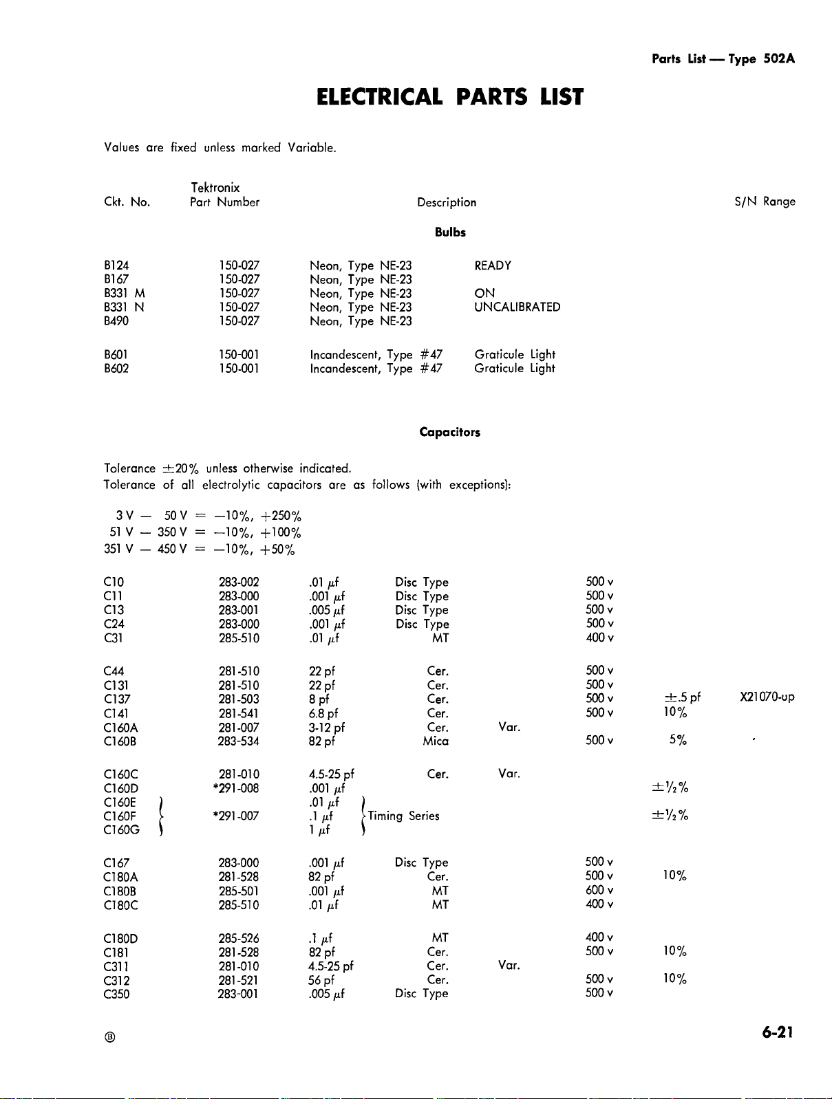
Parts
List
—
Type
502A
Values
Ckt.
No.
B
1
24
B
1
67
B331
M
B331
N
B490
B601
B602
Tolerance
Tolerance
are
±20%
of
fixed
all
unless
Tektronix
Part
Number
150-027
150-027
150-027
150-027
150-027
150-001
150-001
unless
electrolytic
marked
otherwise
Variable.
indicated.
capacitors
ELECTRICAL
Description
Neon,
Type
Type
Type
Type
Type
as
NE-23
NE-23
NE-23
NE-23
NE-23
follows
Type
Type
#47
#47
Capacitors
(with
Neon,
Neon,
Neon,
Neon,
Incandescent,
Incandescent,
are
PARTS
Bulbs
READY
ON
UNCALIBRATED
Graticule
Graticule
exceptions):
Light
Light
LIST
S/N
Range
3
V
51
V
351
V
C10
C
11
C
1
3
C24
C31
C44
C
1
31
C
1
37
C
1
41
C160A
C160B
C160C
C160D
C160E
C160F
C160G
Cl
67
C180A
C180B
C180C
—
50
V
=
-10%,
+250%
350
V
-
-
450
=
-10%,
+100%
V
=
-10%,
+50%
500
283-002
283-000
283-001
283-000
285-510
281-510
281-510
281-503
281-541
281-007
283-534
281-010
*291-008
*291
-007
283-000
281-528
285-501
285-510
.01
μf
.001
.005
.001
.01
μf
22
pf
22
pf
8
pf
6.8
pf
3-12
82
pf
4.5-25
.001
.01
μf
.1
μf
1
μf
.001
82
pf
.001
.01
μf
Disc
Type
μf
μf
μf
pf
pf
μf
μf
μf
Timing
.
Disc
Disc
Disc
Disc
Type
Type
Type
Mica
Series
Type
MT
Cer.
Cer.
Cer.
Cer.
Cer.
Cer.
Cer.
MT
MT
Var.
Var.
500
500
500
400
500
500
500v
500
500
500
500
600
400
v
v
v
v
v
v
v
v
v
v
v
v
v
±.5
pf
10%
5%
±
’
/
2
%
±
’
/
2
%
10%
X21070-up
C180D
C181
C311
C312
C350
285-526
281-528
281-010
281-521
283-001
.1
μf
82
pf
4.5-25
56
pf
.005
400
MT
Cer.
Disc
Type
Cer.
Cer.
pf
μf
Var.
500
500
500
v
v
v
v
10%
10%
6-21

Parts
List
—
Type
502A
Ckt.
No.
C400
†
C401
†
C406A
C406C
C406G
C406J
C406L
C407A
C407C
C407Gt
C407J
C407L
C409B
C409Ct
C409Dt
C409E
C409F
C409G
C409H
C409.l
Capacitors
Tektronix
Part
†
†
†
†
†
†
†
†
†
†
†
†
†
†
†
Number
*295-066
281-012
281-005
281-012
281-005
281-546
281-012
281-005
281-012
281-005
281-546
281-506
281-513
281-528
281-524
283-513
283-522
283-524
283-035
.1
μf
7-45
1.5-7
7-45
1.5-7
330
7-45
1.5-7
7-45
1.5-7
330
12
pf
27
pf
82
pf
150
220
470
750
.0015
pf
pf
pf
pf
pf
pf
pf
pf
pf
pf
pf
pf
pf
pf
μf
Disc
(continued)
Description
PTM
Cer.
Cer.
Cer.
Cer.
Cer.
Cer.
Cer.
Cer.
Cer.
Cer.
Cer.
Cer.
Cer.
Cer.
Mica
Mica
Mica
Type
Var.
Var.
Var.
Var.
Var.
Var.
Var.
Var.
600
500
500
500
500
500
500
500
500
500
500
S/N
Range
v
v
v
v
v
v
v
v
v
v
v
matched
1
10%
10%
10%
10%
10%
5%
5%
within
%
of
each
other
C409K
C409L
C410
†
C440
†
C456t
C469
†
C470
†
C478
†
C480
†
C491
†
C601
C602A,B
C623
C633
C635
C642
C644
C645
C652
C671
C685
C686
C722
C751
C757A,B
C765A,B
†
†
Use
285-510
285-519
281-010
281-010
285-543
281-027
281-005
281-005
281-005
281-534
285-612
*290-092
285-510
285-510
283-057
*290-091
290-025
290-025
*290-043
285-510
290-025
290-025
*290-042
285-511
*290-037
*290-037
.01
.047
4.5-25
4.5-25
.0022
.7-3
1.5-7
1.5-7
1.5-7
3.3
1.5
10
x
.01
.01
.1
μf
4000
6.25
6.25
2
x
.01
6.25
6.25
2
x
.01
2
x
20
2
x
20
μf
μf
40
μf
40
μf
μf
μf
pf
pf
μf
pf
pf
pf
pf
pf
μf
80
μf
μf
μf
μf
μf
μf
μf
μf
μf
μf
Disc
MT
MT
Cer.
Cer.
MT
Tub.
Cer.
Cer.
Cer.
Cer.
PMC
EMC
MT
MT
Type
EMC
EMT
EMT
EMC
MT
EMT
EMT
EMC
PTM
EMC
EMC
Var.
Var.
Var.
Var.
Var.
Var.
400
400
400
500
236
450
400
400
200
300
300
450
400
300
300
450
600
450
450
15v
v
v
v
±.25
v
v
v
v
v
v
v
v
v
v
v
v
v
v
v
v
pf
X20686-up
†
There
6-22
are
two
parts
of
this
description
in
your
instrument,
one
in
each
of
the
Vertical
Amplifiers.
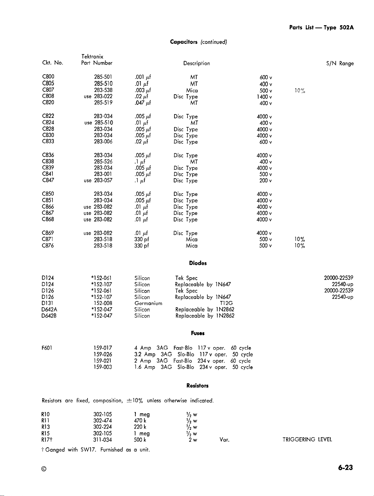
Parts
List
—
Type
502A
Ckt.
C800
C805
C807
C808
C820
C822
C824
C828
C830
C833
C836
C838
C839
C841
C847
C850
C851
C866
C867
C868
Capacitors
No.
Tektronix
Part
Number
285-501
285-510
283-538
use
283-022
285-519
283-034
use
285-510
283-034
283-034
283-006
283-034
285-526
283-034
283-001
use
283-057
283-034
283-034
use
283-082
use
283-082
use
283-082
.001
.01
.003
.02
.047
.005
.01
.005
.005
.02
.005
.1
.005
.005
.1
.005
.005
.01
.01
.01
μf
μf
μf
μf
μf
μf
μf
μf
μf
μf
μf
μf
μf
μf
μf
μf
μf
μf
μf
μf
Disc
Disc
Disc
Disc
Disc
Disc
Disc
Disc
Disc
Disc
Disc
Disc
Disc
Disc
(continued)
Description
MT
MT
Mica
Type
MT
Type
MT
Type
Type
Type
Type
MT
Type
Type
Type
Type
Type
Type
Type
Type
600
400
500
1400v
400
4000
400
4000
4000
600
4000
400
4000
500
200
4000
4000
4000
4000
4000
S/N
Range
v
v
v
v
v
v
v
v
v
v
v
v
v
v
v
v
v
v
v
10%
C869
C871
C876
D
1
24
D
1
24
D126
D
1
26
D131
D642A
D642B
F601
Resistors
4000
use
283-082
283-518
283-518
.01
330
330
μf
pf
pf
Disc
Type
Mica
Mica
500
500
v
v
v
10%
10%
Diodes
*152-061
*152-107
*152-061
*152-107
152-008
*152-047
*152-047
Silicon
Silicon
Silicon
Silicon
Germanium
Silicon
Silicon
Tek
Spec
Replaceable
Tek
Spec
Replaceable
Replaceable
Replaceable
by
by
by
by
1N647
1N647
T12G
1N2862
1N2862
20000-22539
22540-up
20000-22539
22540-up
Fuses
117
v
117
234
234
oper.
60
cycle
50
60
50
cycle
cycle
cycle
v
oper.
v
oper.
v
oper.
4
Amp
3AG
159-017
159-026
159-021
159-003
3.2
2
1.6
Amp
Amp
Amp
3AG
3AG
3AG
Fast-Bio
Fast-Bio
Slo-Blo
Slo-Blo
Resistors
are
fixed,
composition,
±10%
unless
otherwise
indicated.
R10
R
11
R13
R15
R17t
t
Ganged
with
SW17.
302-105
302-474
302-224
302-105
311-034
Furnished
1
meg
470
k
220
k
1
meg
500
k
as
a
unit.
'/
2
w
'/
2
w
'/
2
w
y
2
w
2w
TRIGGERING
LEVEL
6-23

Parts
List
—
Type
502A
Ckt.
R18
R21
R23
R24
R26
R27
R29
R32
R33
R36
R39
R42
R44
R47
R48
R51
R
111
R114
R116
R121
R122
Resistors
Tektronix
No.
Part
use
Number
302-124
302-101
304-473
311
-005
302-333
302-101
301-204
302-275
302-101
306-223
309-126
302-101
309-056
301-302
302-681
302-392
311
-032
302-104
302-394
316-103
301-274
120
100
47
500
33
100
200
2.7
100
22
400
100
390
3
680
3.9
250
100
390
10
270
k
Ω
k
Ω
k
Ω
k
meg
Ω
k
k
Ω
k
k
Ω
k
k
k
k
k
k
(continued)
Description
½W
½W
1 W
2 W
½W
½W
½W
½W
½W
2
w
½W
½W
½W
½W
½W
½W
2 W
½W
½W
½W
½W
Var.
Var.
Prec.
Prec.
TRIG.
LEVEL
5%
1%
1%
5%
STABILITY
5%
CENT.
ADJUST
S/N
Range
X21070-up
R123
R124
R125
R126
R127
R128
R131
R134
R136
R137
R137
R141
R143
R144
R144
R146
R147
R148
R160A
R160B
R160C
R160D
R160E
R160F
R160G
R160T
R160V
R161
302-183
302-683
302-154
use
302-334
302-153
302-184
302-472
301-393
303-224
302-101
302-473
309-040
309-176
324-309
324-323
302-101
302-222
302-184
309-014
309-023
309-087
309-095
309-095
310-061
310-061
†
302-822
311-108
302-101
18
68
150
330
15
180
4.7
39
220
100
47
56.5
43.4
16.2
22.6
100
2.2
180
1
2
5
10
10
15
15
8.2
20
100
k
k
k
k
k
meg
meg
meg
meg
meg
meg
meg
k
k
k
k
k
k
Ω
k
k
k
k
Ω
k
k
k
Ω
½W
½W
½W
½W
½W
½W
½W
½W
1 W
½W
½W
½W
½W
1 W
1 W
½W
½W
½W
½W
½W
½W
½W
½W
1 W
1 W
½W
½W
Var.
Prec.
Prec.
Prec.
Prec.
Prec.
Prec.
Prec.
Prec.
Prec.
Prec.
Prec.
WW
5%
5%
1%
1%
1%
1%
1%
1%
1%
1%
1%
2%
2%
VARIABLE
(Ti
20000-21069
21070-up
20000-22539
22540-up
me/CM)
†
Concentric
6-24
with
SW160V.
Furnished
as
a
unit.
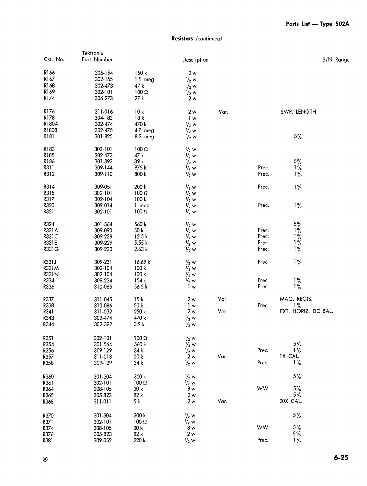
Parts
List
—
Type
502A
Ckt.
R166
R1
67
R168
R1
69
R174
R1
76
R178
R180A
R180B
R181
R183
R185
R186
R311
R312
R314
R315
R317
R320
R321
No.
Tektronix
Part
Number
306-154
302-155
302-473
302-101
306-273
311-016
304-183
302-474
302-475
301-825
302-101
302-473
301-393
309-144
309-110
309-051
302-101
302-104
309-014
302-101
Resistors
150
k
1.5
meg
47
k
100
Ω
27
k
10k
18k
470
k
4.7
meg
8.2
meg
100
47
39
975
800
200
100
100
1
100
Ω
k
k
Ω
k
meg
Ω
k
k
k
½W
(continued)
Description
2 W
½W
½W
½W
2 W
2 W
1 W
½W
½W
½W
½W
½W
½W
½W
½W
½W
½W
½W
½W
Var.
Prec.
Prec.
Prec.
Prec.
SWP.
LENGTH
5%
5%
1%
1%
1%
1%
S/N
Range
R324
R331A
R331C
R331E
R331G
R331J
R331M
R331N
R334
R336
R337
R338
R341
R343
R344
R351
R354
R356
R357
R358
R360
R361
R364
R365
R368
301-564
309-090
309-228
309-229
309-230
309-231
302-104
302-104
309-234
310-065
311-045
310-086
311-032
302-474
302-392
302-101
301-564
309-129
311-018
309-129
301-304
302-101 100
308-105
305-823
311-011
560
50
12.5
5.55
2.63
16.69
100
100
154
56.5
15
50
250
470
3.9
100
560
34
20
34
300
30
82
5k
MAG.
EXT.
IX
20X
5%
1%
1%
1%
1%
1%
1%
1%
1%
HORIZ.
5%
1%
CAL.
1%
5%
5%
5%
CAL.
REGIS.
BAL.
DC
k
k
k
k
k
k
k
k
k
k
k
k
k
k
k
Ω
k
k
k
k
k
Ω
k
k
½W
½W
½W
½W
½W
½W
½W
½W
½W
1 W
2 W
1 W
2 W
½W
½W
½W
½W
½W
2 W
½W
½W
½W
8
2 W
2 W
Prec.
Prec.
Prec.
Prec.
Prec.
Prec.
Prec.
Var.
Var.
Var.
W
Var.
Prec.
Prec.
Prec.
WW
R370
R371
R374
R376
R381
301
-304
302-101
308-105
305-823
309-052
300
100
30
82
220
k
Ω
k
k
k
½W
½W
8
2
½W
W
W
WW
Prec.
5%
5%
5%
1%
6-25

Parts
List
—
Type
502A
Ckt.
R383
R385
R386
R391
R393
R395
R396
R398
R406C
R406E
R406J
R406L
R407C
R407E
R407.
R407L
R408A
R408B
R408C
R408D
No.
†
†
†
†
J
†
†
†
Resistors
Tektronix
Part
†
†
†
†
†
Number
301-204
302-223
302-223
309-052
301-204
302-223
302-223
311-416
309-111
309-046
309-013
309-034
309-111
309-046
309-013
309-034
309-243
309-090
309-231
309-229
200
k
22
k
22
k
220
k
200
k
22
k
22
k
2
x50
k
900
k
111
k
990
k
10.1
k
900
k
111
k
990
k
10.1
k
193
k
50
k
16.69
k
5.55
k
(continued)
Description
½W
½W
½W
½W
½W
¼W
½W
½W
½W
½W
½W
½W
½W
½W
½W
½W
½W
½W
½W
Var.
Prec.
Prec.
Prec.
Prec.
Prec.
Prec.
Prec.
Prec.
Prec.
Prec.
Prec.
Prec.
Prec.
5%
1%
5%
POSITION
1%
1%
1%
1%
1%
1%
1%
1%
1%
1%
1%
1%
S/N
Rarje
R408E
R408F
R408G
R408H
R408
R408K
R408L
R409B
R409C
R409D
R409E
R409F
R409G
R409H
R409J
R410
R411
R413
R414
R417
R418
R422
R423
R424
R425
R427
J
†
†
†
†
†
†
†††
†
†
†
†
†
†
†
†
†
†
†
†
†
†
†
†
†
†
†
Use
309-230
309-241
309-203
309-178
309-240
309-128
309-177
316-123
315-103
316-392
315-272
315-222
316-152
315-102
315-331
*312-583
302-102
301-564
309-049
301-273
301-472
316-105
301-913
311-347
301-913
309-432
††
2.63
1.28
505.4
25
0
125
50
Ω
25
Ω
12
10
3.9
2.7
2.2
1.5
1
k
33
0
1
meg
1
k
560
150
27
4.7
1
meg
91
100
91
82.5
k
k
Ω
Ω
Ω
k
k
k
k
k
k
Ω
k
k
k
k
k
k
k
k
½W
½W
½W
½W
½W
½W
½W
¼W
¼W
¼W
¼W
¼W
¼W
¼W
¼W
½W
½W
½W
½W
½W
½W
¼W
½W
.2 W
½W
½W
Var.
Prec.
Prec.
Prec.
Prec.
Prec.
Prec.
Prec.
Prec.
Prec.
Prec.
.2
V/CM
1%
1%
1%
1%
1%
1%
1%
5%
5%
5%
5%
5%
1%
5%
1%
5%
5%
5%
5%
1%
DIFF.
BAL.
X21070-up
†
There
††
†††
6-26
R410
Selected
are
and
two
R440
part;
parts
may
are
of
a
not
this
description
matched
appear
in
pair.
in
Furnished
your
your
instrument.
instrument;
as
a
unit.
one
in
each
of
the
Vertical
Amplifiers,

Parts
List
—
Type
502A
Ckt.
R428
R429
R433
R434
R435
R440
R441
R443
R444
R447
R448
R450
R451
R452
R453
R454
R455
R456
R457
R458
Resistors
No.
†
†
†
†
†
†
†
†
†
†
†
†
†
†
†
†
†
†
†
†
Tektronix
Part
Number
309-432
311-017
311-243
301-272
311-125
*312-583
302-102
301
-564
309-049
301-273
301-472
306-473
302-102
309-414
306-153
301-303
311-067
311-084
301-223
301-223
††
82.5
10
50
2.7
50
1
1
560
150
27
4.7
47
1
5
15k
30
5
1
22
22
meg
k
k
meg
k
k
k
k
k
k
k
k
k
k
k
k
k
k
k
(continued)
Description
½W
.1
W
½W
.2 W
½W
½W
½W
½W
½W
½W
2 W
½W
½W
2
W
½W
.2 W
.2 W
½W
½W
Var.
Var.
Var.
Var.
Var.
Prec.
Prec.
Prec.
Prec.
1%
VAR.
DC
DC
BAL.
5%
.2
MV/CM
1%
5%
1%
5%
5%
1%
5%
FEEDBACK
.2
MV/CM
5%
5%
BAL.
BAL.
GAIN
DIFF.
S/N
BAL.
Range
R461
R462
R464
R465
R466
R467
R468
R469
R470
R471
R472
R473
R474
R475
R476
R478
R479
R480
R481
R482
R483
R484
R48
R486
R487
5†
†
†
†
†
†
†
†
†
†
†
†
†
†
†
†
†
†
†
†
†
†
†
†
†
Use
Use
Use
Use
302-102
309-414
301-303
301-565
311-028
301-565
302-103
302-103
309-195
302-102
304-223
302-102
305-273
306-333
306-273
302-472
302-472
309-195
302-102
304-223
302-102
305-273
306-333
306-273
311-399
1
5
30
5.6
2
5.6
10
10
90
1
22
1
27
33
27
4.7
4.7
90
1
22
1
27
33
27
7k
k
meg
x
k
k
k
k
k
k
k
k
k
k
k
k
k
k
k
k
k
meg
100
meg
k
k
½W
½W
½W
k
½W
2 W
½W
½W
½W
½W
½W
1
½W
2
2
2
½W
½W
½W
½W
1
½W
2
2
2
Var.
W
W
W
W
W
W
W
W
Var.
Prec.
Prec.
Prec.
1%
5%
5%
POSITION
5%
1%
5%
1%
5%
VARIABLE
(Sensitivity)
††
†
There
R41
are
two
parts
of
this
description
0
and
R440
are
a
matched
pair.
in
Furnished
your
instrument;
as
one
in
each
of
the
Vertical
Amplifiers,
a
unit.
6-27

Parts
List
—
Type
502A
Ckt.
R488
R489
R490
R491
R492
R494t
R495
R499
R601
R602
R603
R604
R618
R619
R621
R622
R623
R630
R631
R632
Resistors
No.
†
†
†
†
†
††
Tektronix
Part
Number
311-120
311-067
302-683
309-086
309-021
302-224
311-125
304-473
311-057
302-101
302-101
308-142
302-102
302-105
310-054
311-015
310-086
302-333
302-105
302-102
2.5
k
5
k
68
k
3.5
meg
1.84
meg
220
k
50
k
47
k
50
Ω
100
Ω
100
Ω
30
Ω
1
k
1
meg
68
k
10
k
50
k
33
k
1
meg
1
k
(continued)
Description
.2W
.2W
½W
½W
½W
½W
.2W
1 W
½W
½W
3
W
½W
½W
1 W
1 W
½W
½W
½W
Var.
Var.
Var.
Var.
Var.
Prec.
Prec.
WW
ww
Prec.
WW
Prec.
GAIN
.2
V/CM
ADJ.
DC
SCALE
-150
1%
1%
TRIG.
5%
1%
VOLTS
1%
GAIN
FOR
I
LLUM.
HORIZ.
S/N
Range
MODE
R633
R635
R636
R637
R639
R642
R643
R644
R645
R646
R647
R648
R649
R650
R651
R659
R660
R661
R662
R665
R666
R668
R669
R671
R673
302-105
302-183
302-105
308-040
302-333
302-104
302-104
302-101
302-101
306-150
306-150
309-030
310-068
302-470
302-470
302-102
302-473
302-473
302-185
306-273
302-105
302-102
302-105
310-088
310-055
1
meg
18k
1
meg
1.5
k
33
k
100
k
100
k
100
Ω
100
Ω
15
Ω
15
Ω
1.8
k
42.226
47
Ω
47
Ω
1
k
47
k
47
k
1.8
meg
27
k
1
meg
1
k
1
meg
143
k
220
k
½W
½W
½W
25 W
½W
½W
½W
½W
½W
2 W
2 W
½W
k
1 W
½W
½W
½W
½W
½W
½W
2 W
½W
½W
½W
1 W
W
WW
Prec.
Prec.
Prec.
Prec.
5%
1%
1%
1%
1%
†
There
††
Ganged
6-28
are
two
parts
of
this
with
SW601.
Furnished
description
in
your
instrument;
as
a
unit.
one
in
each
of
the
Vertical
Amplifiers,

Parts
List
—
Type
502A
Ckt.
R685
R686
R722
R739
R740
R741
R742
R745
R746
R747
R748
R749
R751
R753
R756
R757
R765
R766
R800
R805
Resistors
Tektronix
No.
Part
Number
302-101
302-101
302-104
302
102
302-273
302-474
304-274
304-563
302-225
302-102
302-102
302-225
310-094
309-151
302-102
308-064
302-101 100
302-101 100
306-563
302-333
100
100
100
1
27
470
270
56
2.2
1
1
2.2
400
174
1
2.25
56
33
Ω
Ω
k
k
k
k
k
k
meg
k
k
meg
k
k
k
k
Ω
Ω
k
k
(continued)
Description
½W
½W
½W
½W
½W
½W
1 W
1 W
½W
½W
½W
½W
1 W
½W
½W
20 W
½W
½W
2 W
½W
Prec.
Prec.
WW
S/N
1
1
5%
%
%
R806
R808
R809
R820
R824
R825
R826
R827
R828
R829
R830
R831
R832
R833
R834
R836
R837
R838
R839
R840
R841
R842
R843
R844
R845
302-392
306-122
302-474
302-102
316-472
306-225
311
-039
306-275
306-335
306-335
306-395
311-254
311-254
311
-026
316-472
306-395
302-103
302-103
302-105
311-026
311-026
311-023
304-273
311
-026
304-273
3.9
1.2
470
1
4.7
2.2
1
2.7
3.3
3.3
3.9
5
5
100
4.7
3.9
10k
10k
1
100
100
50
27
100
27
k
meg
meg
meg
meg
k
k
k
k
k
k
k
meg
meg
meg
meg
meg
k
k
meg
k
k
k
½W
2 W
½W
½W
¼W
2
2
2
2
2
2
.2
.2
2
¼W
2
½W
½W
½W
2
2
2
1W
2
1
W
W
W
W
W
W
W
W
W
W
W
W
W
W
W
Var.
Var.
Var.
Var.
Var.
Var.
Var.
Var.
HIGH
FOCUS
FOCUS
HORIZ.
ASTIG.
GEOM.
HORIZ.
ASTIG.
VOLTAGE
Lower
Upper
SENS.
LOWER
BEAM
UPPER
Beam
Beam
BAL.
REGIS.
R846
R847
R852
R853
R854
302-155
302-225
306-825
306-825
306-825
1.5
2.2
8.2
8.2
8.2
meg
meg
meg
meg
meg
½W
½W
2
2
2
W
W
W
6-29

Parts
List
—
Type
502A
Ckt.
R858
R859
R860
R861
R862
R863
R864
R865
R866
R868
R870
R871
R872
R874
R875
R876
R878
R879
R880
R883
R884
R885
R886
Resistors
Tektronix
No.
Part
Number
306-156
306-156
311-397
304-105
311-397
302-226
302-563
302-226
302-105
302-105
302-154
302-335
302-102
302-683
302-225
302-102
302-473
311-016
304-333
302-101
309-237
310-066
309-030
15
meg
15
meg
2
meg
1
meg
2
meg
22
meg
56
k
22
meg
1
meg
1
meg
150
k
3.3
meg
1
k
68
k
2.2
meg
1
k
47
k
10k
33
k
100 Ω
204
Ω
18
k
1.8
k
(continued)
Description
2
W
2
W
1
W
½W
½W
½W
½W
½W
½W
½W
½W
½W
½W
½W
½W
2
W
1
W
1
W
1
W
1
W
½W
Var.
Var.
Var.
Prec.
Prec.
Prec.
INTENSITY
INTENSITY
CAL.
AMPL.
1%
1%
1%
BAL.
S/N
Range
R887
R888
R889
R890
R899
SW10
SW17
†
SW20
SW126
SW160
SW160V
SW331
SW403A
SW403B
SW407
SW478
SW489
SW601
SW870
TK601
†
Ganged
†
Concentric
††
There
††
Ganged
††
††
†††
Use
†
††
††
are
Unwired
260-233
260-235
260-447
260-501
260-529
311-108
260-236
260-238
260-238
260-525
260-247
260-237
311-057
260-234
260-208
with
with
two
with
R17.
R160V.
parts
309-235
309-236
309-238
309-096
*308-090
Wired
*262-177
*262-178
*262-556
*262-172
*262-179
*262-190
*262-555
*262-180
*262-176
Furnished
R601.
Furnished
of
this
Furnished
as
a
as
description
as
9k
900
90
10
.25
unit.
a
Ω
Ω
Ω
a
Ω
Rotary
Rotary
Slide
Lever
Rotary
Rotary
Rotary
Rotary
Rotary
Push-button
Rotary
Rotary
Thermal
unit.
in
your
unit.
Cutout
instrument;
½W
½W
½W
½W
1
W
Switches
133°
one
TRIGGER
TRIGGERING
TRIGGER
MODE
TIME/CM
HORIZONTAL
INPUT
INPUT
SENSITIVITY
FINDER
HORIZ.
POWER
AMPLITUDE
F
±
in
each
5°
SELECTOR
SELECTOR
SELECTOR
SELECTOR
(Trace)
DEFL.
OFF
F
of
the
LEVEL
DISPLAY
(Upper)
(Lower)
PLATE
CALIBRATOR
Vertical
Prec.
Prec.
Prec.
Prec.
WW
(Slope)
SELECTOR
Amplifiers,
1%
1%
1%
1%
6-30
@3

Transformers
Parts
List
—
Type
502A
Ckt.
T602
T801
Q
1
Q634
Q644
Q647
V24
V45
V
1
V
1
45
V
1
35
52
24
Tektronix
No.
Part
Number
*120-117
*120-150
S/N
Description
L.
V.
Power
H.
V.
Power
Range
Transistors
151
Use
151-004
151-004
151-137
154-187
154-187
154-078
154-078
154-016
-093
2N2043
2N214
2N214
2N2148
6DJ8/ECC88
6DJ8/ECC88
6AN8
6AN8
6AL5
Electron
Tubes
V
1
V
1
V324
V354
V364
V414
V444
V454
V464
V474
V484
V493
V602
V636
V637
V639
V652
V666
V677
V722
V746
V747
V757
V800
V814
61
83
154-078
154-187
154-022
154-022
154-187
†
†
†
†
†
†
†
*157-073
154-022
154-022
154-039
154-039
154-022
154-168
154-078
154-044
154-052
154-119
154-078
154-044
154-168
154-078
154-044
154-044
154-302
154-041
††
6AN8
6DJ8/ECC88
6AU6
6AU6
6DJ8/ECC88
6AU6
6AU6
6AU6
12AT7
12AT7
6AU6
5AR4/GZ34
6AN8
12B4
5651
6BW4
6AN8
12B4
5AR4/GZ34
6AN8
12B4
12B4
6DT5
12AU7
†
There
††
V414
are
two
parts
of
this
description
and
V444
furnished
as
a
unit.
in
your
instrument;
one
in
each
of
the
Vertical
Amplifiers.
6-31

Parts
List
—
Type
502A
Ckt.
V822
V832
V859
V862
V873
V875
Electron
Tektronix
No.
Part
Number
154-051
154-051
*154-246
154-051
154-078
154-022
5642
5642
T5021-2
5642
6AN8
6AU6
CRT
Standard
Tubes
Description
Phosphor
(continued)
S/N
Range
6-32

TYPE
502A
OSCILLOSCOPE
A

A
BLOCK
DIAGRAM
MRH
Z6>3.

+
TYPE
502A
OSCILLOSCOPE)
A

CIRCUIT
NUMBERS
1
THRU
59
I-I
xj
263
A
TIME-BASE
TR
IGGER

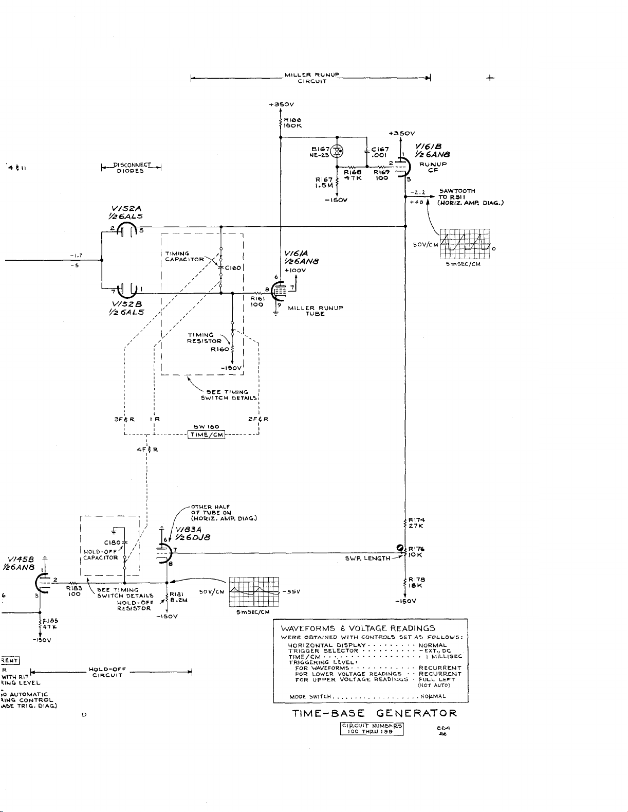
^ENT
R
WITH
Rll
^ING
LEVEL
>0
AUTOMATIC
KIHG
CONTROL
■At>E
TRIG.
-15OV
k-
1
PJ
41
DlAG)
as
K.
HOLD-OFF
CIRCUIT
-I5OV
___________________
WAVEFORMS
WERE
HORIZONTAL
TRIGGER
TIME/CM
TRIGGERING
j
“
FOR
FOR
FOR
MODE
TIME-BASE
4
OBTAINED
WAVEFORMS
LOWER VOLTAGE
UPPER
SWITCH
VOLTAGE
WITH
DISPLAY
SELECTOR
• •
•.
.........................................................
LEVEL
............................................
VOLTAGE
.............................................................
rciRCuTT
1
I
00
2
READINGS
CONTROLS
....................................
THRU
BETAS
.................................
READINGS
READINGS
GENERATOR
NUMBERS
I
89
NORMAL
-
EXT.,
I
RECURRENT
- -
RECURRENT
•
FULL
(MOT
NOR.MAL
|
|
FOLLOWS:
DC
MILLISEC
LEFT
AUTO)

TI
RESI
M
5TORS
I
NG
TIMING
CAPACITORS
TYPE
502
A
OSCILLOSCOPE

TIM
ING
CAPACITORS
SWI6O
HOLD-OFF
4
RESISTORS
CAPACITORS
o
A
TIMING
SWITCH
job

SWEEP
FROM
CATH,
RUNUP
(TIME-BASE
WAVEFORM
PIN
CF
GEN.
3,
VI6IB
...
»
.........—
DI
AG.)
R3H
97SK
'■
11
VOLTAGE
WITH
READINGS
CONTROLS
HORIZONTAL
TRIGGER
TRIGGERING
HORIZONTAL
FOR
FOR
LOWER
UPPER
SET
DISPLAY
SELECTOR
LEVEL
POSITIONS
VOLTAGE
VOLTAGE
were
AS
obtained
FOLLOWS:
READINGS
READINGS
NORMAL
—
EXT.,
FULL
BUT
NOT
TO
AUTOMATIC
FULL
FULL
LEFT
RIGHT
LEFT
DC
SWITCHED
TYPE
502A
OSCILLOSCOPE

^1*
INPUT
AMPLIFIER
OUTPUT
AMPLIFIER
CIR.CUIT
A!
300
THR.U
NUMSER.5
399
ZG3
joe

L
______________________
P
TYPE.
5O2A
CHANNEL
ATTENUATOR
OSCILLOSCOPE
A
_____________________
L
J
J
______________________
r
CHANNEL
ATTENUATOR
E>
A

CMO
363
VERTICAL
A
ATTENUATOR
SWITCH
 Loading...