

Page 1

Tektronix 49x/275x-Series Spectrum Analyzer
____________________
John Miles, KE5FX
jmiles@pop.net
March 29, 2009
Service Notes
Page 2

This public-domain document may be reproduced and distributed freely.
The latest edition is available at http://www.ke5fx.com/49x_notes.pdf
.
Page 3

Errata and helpful notes on calibration/service procedures
Page numbers refer to 494/P service volume 1, 070-4416-00, but in most cases there are
equivalent pages/sections in all other 49x/275x manuals
3. Deflection amplifier (gain and frequency response), p. 5-6
Step 3b: Apply a 500-kHz signal... In later editions (e.g. 494A/P volume 2, 070-5561-00), this was
corrected to 500 Hz.
Step 3b: ... and set Triggering to Int. I've found that at least some models need to be left in FREE
RUN mode to trigger on the specified video waveform.
The 49x/275x deflection amplifier underwent several revisions throughout production, including a
complete redesign in 1988. Regardless of your instrument model, refer to the manual change
information in the 494/A manual (070-5560-00) if your instrument has one of these newer
subassemblies.
Don't forget to disable digital storage before adjusting the X/Y deflection gain. Recalibrate the
digital storage subsystem immediately after any adjustments are made.
5. Frequency Control System Calibration, p. 5-9
Step e: When observing the markers, either turn digital storage off, or follow the procedure in 13.
Digital storage calibration first. I recommend calibrating digital storage immediately after the
deflection amp gain, so you aren't confused in any subsequent steps by storage-registration
errors. This is reflected in later manuals such as the 494A/P's.
Step e-3: ...apply 0.2 us time marks from the time mark generator to the RF input. Any 5-MHz
sinewave source is OK for this, especially if it's strong enough to create some additional harmonic
distortion in the front end. Select 100 kHz RBW to yield narrower markers.
Step f: Max Span Dot Don't bother to change the resistor based on the response at the left end of
the display, as the manual specifies. Change the resistor only if the dot marker is substantially
out of alignment at higher-frequency markers, e.g. at 1.8 GHz in step f-3. (The 1.8 GHz marker
may be too weak to see; neighboring markers are OK for this test as well.)
Figure 5-10: Adjustment and test point locations for calibrating the frequency control
system, p. 5-11
TP1073 is located on the Span Attenuator circuit board, not the 1st LO Driver circuit board as
shown in the 494/P and earlier manuals.
8. Log Amplifier Calibration, p. 5-14
This procedure involves various interacting control settings, ambiguous instructions, and printing
errors. Don't adjust your logamp unless you actually need to. Symptoms such as excessive
amplitude drift will not be corrected by calibration alone.
While Tektronix continually upgraded their instruments to use the latest modules in production,
the same cannot be said of their service manuals. Calibration-procedure change notes were
never issued in many cases, so it's best to follow the instructions in later 49x/275x instrument
manuals whenever they apply to the modules in your instrument. When searching for the correct
Page 4
schematics and service information for your instrument, date codes on components are often a
better clue than the model nomenclature on the front panel.
For example, you may not need to install your logamp on extenders and remove its covers, as
recommended in step 8b on page 5-14 of the 494/P manual, if your logamp's control adjustments
are easily accessible through the slots in the housing as they were in all later instruments.
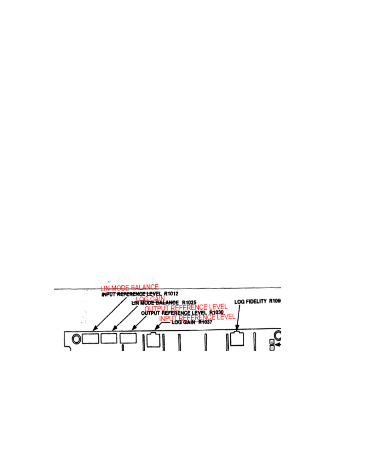
The first step in logamp calibration is to identify which of the three possible Log and Video
Amplifier test point and adjustment locations figures (5-17 in 070-4416-00, or 5-13 in 0705560-00 with two possible control layouts) applies to the module in your instrument. An analyzer
with the older-style logamp uses figure 5-17 in the 494/P manual, while logamps in newer
492A/492B/494/495/497 analyzers and their 275x-series counterparts use the physical layout in
figure 5-13 of the 494A/P manual.
The catch is that at least two different layouts were used for the controls in figure 5-13. At some
point, probably around the time Tek redesigned the board using surface-mount components in
the late 1980s-early 1990s, the trimmer functions were reordered while their physical locations
were left alone. In earlier logamp assemblies, the order is as specified (left-to-right on the
component side):
INPUT REFERENCE LEVEL R1012
LIN MODE BALANCE R1025
OUTPUT REFERENCE LEVEL R1030
LOG GAIN R1037
LOG FIDELITY R1060
In later assemblies, the correct control order is:
LIN MODE BALANCE R1025
LOG GAIN R1037
OUTPUT REFERENCE LEVEL R1030
INPUT REFERENCE LEVEL R1012
LOG FIDELITY R1060
Step h: Return the step attenuator to 0 dB. Display should be full screen (+6 dBm); if not,
readjust the signal generator output for +6 dBm. This confusing step was modified in the later
494A/P manual (step i) but never actually "fixed." The overall goal is to achieve and maintain
fullscreen (reference-level) response with +6 dBm at the input to the logamp. It's not clear what
Tek's intention was when documenting this part of the calibration procedure, but it appears the
intent is for the vertical position control to be adjusted to maintain a fullscreen indication with +6
dBm. If someone has a better interpretation, please email me and help keep this document up to
date!
Page 5

Note that 492/496 logamp modules used 0 dBm as a reference level rather than +6 dBm.
If your signal generator has a calibrated attenuator (HP 8656/8657/8642/8662 etc.), you obviously
don't need to bother with the step attenuators. Users of HP 8640s and other generators with
vernier level controls will probably find it easier to use the outboard attenuators as specified.
When servicing your logamp module, watch out for corrosion from any surface-mount electrolytic
capacitors that may be present. 494AP-era logamps were among the earlier surface-mount
assemblies produced by Tektronix in the late 1980s. The quality of the surface-mount capacitors
used at the time was terrible, as owners of other Tek instruments such as the early TDS-series
DSOs can often attest. I've had to junk at least one logamp module due to instability and
intermittents caused by this corrosion.
8. Adjust Resolution Bandwidth and Shape Factor, p. 5-14 of 494A/P manual (070-5560-00)
Step i: At the conclusion of this part of the procedure, reconnect J693.
13. Digital Storage Calibration, p. 5-22
The layout shown for the trimpots on the horizontal digital storage board in figure 5-24 is wrong.
The correct order for these controls (from left to right) is:
OUTPUT OFFSET R1039
OUTPUT GAIN R1041
INPUT OFFSET R1046
INPUT GAIN R1048
Unlike the logamp controls above, I don't believe this control layout varies with the board revision.
As noted elsewhere, the digital storage controls should be aligned much earlier in the calibration
process than the 494P manual recommends. Perform this procedure immediately after servicing
or recalibrating the deflection amp.
15. Preselector Driver Calibration, p. 5-24
Follow the procedure 13. Adjust Preselector Driver, p. 5-21 in the 494A/P service manual when
aligning the preselector. It's normal for the 19- and 21-GHz response peaks to be rather broad,
or to occur at the far extent of their respective shaper adjustments.
In most cases it will not be possible to achieve perfect preselector tracking in any one band, much
less across all bands, and in any event, thermal factors will limit repeatability. You can spend
hours tweaking the preselector response if you like, but as soon as you put the cover back on the
analyzer, the effort will be wasted.
Ultimately the response with the PEAKING control centered may be 3-4 dB down at various
frequencies in the different bands, but with correct alignment, it should be possible to peak the
response at any given frequency between 1.7 and 21 GHz without leaving the shaded area. If
your preselector response already meets this criterion, there is little benefit in adjusting the
preselector driver assembly.
If the TM500-series time-mark generator and comb generator specified by Tek are not available,
an HP 33002A SRD comb generator module driven by a +23 dBm, 100 MHz signal source makes
a good substitute. You can also perform the procedure with a CW-capable sweep generator
(e.g., HP 86290A-H08) or synthesizer (HP 8673B or equivalent), but it's more time-consuming.
Absolute amplitude control is not needed for preselector calibration.
Page 6

Maintenance: Replacing the Crt, p. 6-29
Like the logamp alignment instructions, this is an area of the manual where the engineers and
technical writers at Tektronix never quite found themselves on the same page. Personal injury
or equipment damage can result from following Tektronix's CRT installation procedure.
The key point is simple: before reinstalling the clear plastic implosion shield and metal bezel
frame, you should loosen the four plastic mounting blocks around the perimeter of the new CRT's
face. This will allow the CRT to rest as far back in the instrument as possible while the bezel is
being tightened. The goal is to be able to tighten the bezel's four Allen screws in a cross pattern
without putting any pressure on the CRT face. You should be able to slide the implosion
shield around freely with one hand while you tighten each bezel screw. If the plastic shield
binds up as you tighten one of the bezel screws, the mounting-block screw at that corner is still
too tight.
In particular, don't follow step 6 on page 6-30 of the 494P manual (070-4416-00) ("remove the
bezel and tighten the mounting block screws..."), or any similar instructions that may be in your
edition of the service manual. Instead, once the bezel screws are tight and you've verified that
the plastic shield is still free to slide across the CRT face, tighten the mounting block screws
evenly in a cross pattern to approximately 8 inch-pounds, with the bezel still in place. This
procedure will bind the CRT with a safe amount of pressure, allowing it to undergo normal
handling jolts without overstressing either the CRT face or the plastic implosion shield.
It's not necessary to follow any instructions in the manual regarding removal of the old CRT from
its shield cladding. There's no reason to do this unless your replacement CRT didn't come with
its own shield.
Page 7
Troubleshooting topics
General notes on power-supply service
Regulation tolerances for the low-voltage supply buses are specified in service volume 1, and are
not usually a problem. However, the +100V and +300V supplies are frequently below their
specified values. If any 66-kHz ripple or sagging is observed, all of the miniature 2.2 uF/200V
axial-lead electrolytic capacitors in the power supply should be replaced. These are inexpensive
high-failure-rate parts, so they should be replaced in any event if the power supply is otherwise
disassembled for service.
I recommend checking the ESR on any replacement high-voltage electrolytics as well. Several
"new" capacitors in this voltage range have proven defective when obtained from surplus
sources.
High ESR in the filter capacitors on the lower-voltage rails (+17V, +5V) has been reported as a
cause of excessive power-supply temperature, so when servicing the power supply, you should
check ESR on all electrolytics as a matter of habit. Check heat-sink fasteners for tightness, and
renew the heat-sink compound while you're at it. Avoid losing track of the mica washers and
aluminum spacers that may fall out when you remove the PCB.
Use 105 degree C-rated electrolytics where possible, e.g., 3.3 uF 350V 105C, Digi-Key
493-2046-ND. These can replace all of the high voltage capacitors on the power supply (6x
2.2uF/200V, 1x 1uF/350V).
part #
According to a Usenet post (sci.electronics.equipment, 2-Sep-01), the large stud-mounted
transistors with Tektronix part number 151-0703-00 cross-reference to the industry-standard part
number 2N6586 (10A/450V, 12.5 MHz fT, TO61 package).
Page 8

Symptom: Display noise/jitter
The 49x/275x CRT display subsystem is one of its weaker areas. You will not see HP-like levels
of display stability and sharpness on these instruments, but there's often a lot of room for
improvement.
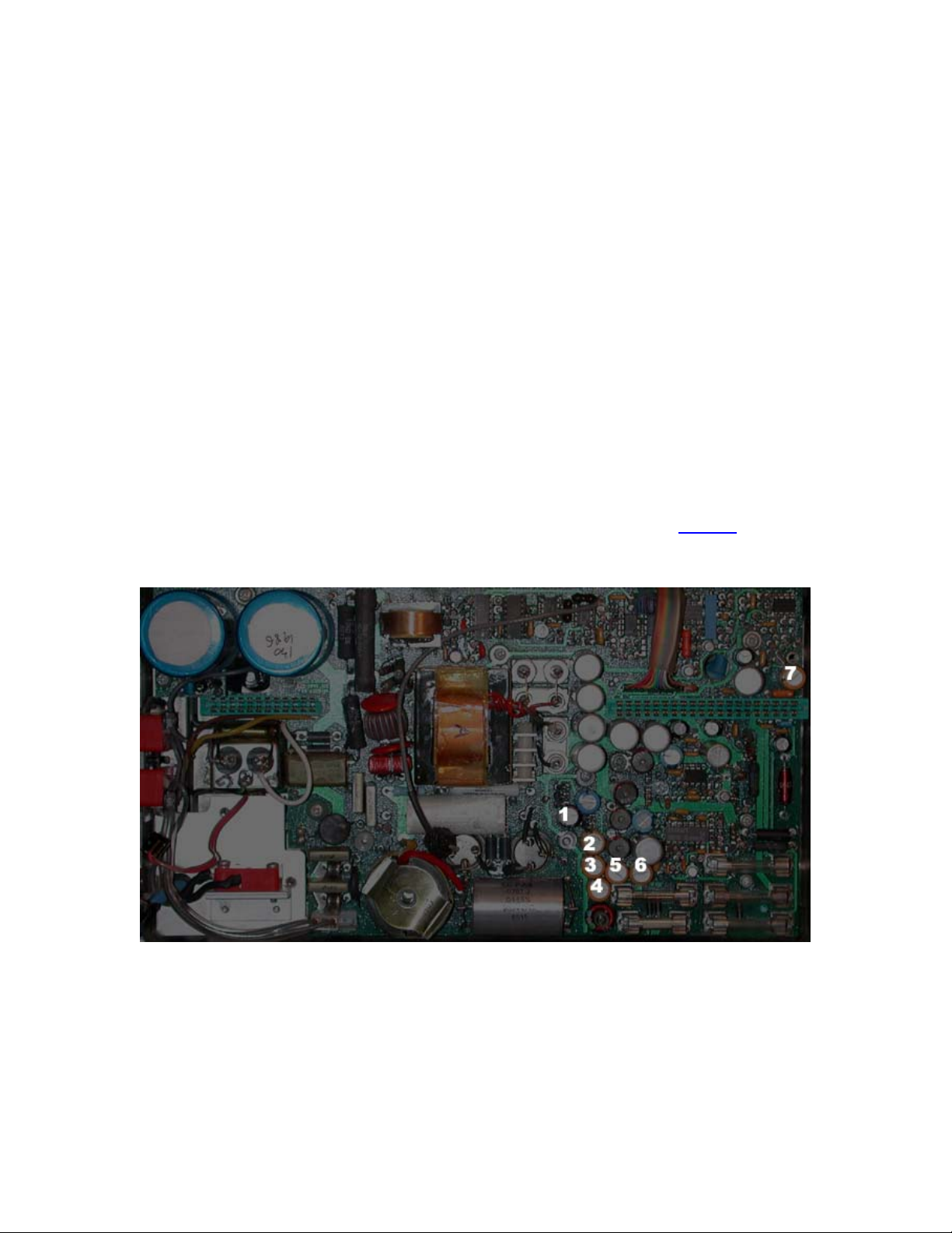
When servicing instruments with the pre-1988 deflection amplifiers, it's a good idea to replace the
620K and 300K carbon-composition resistors in the negative-feedback paths. Many of these
resistors have drifted upward over time, and/or become noisy. Typical replacement parts would
be Digi-Key
deflection amplifier and digital storage subassemblies after replacing these resistors.
P620KBBCT-ND (two each) and BC300KW-2CT-ND (two each). Calibrate the
This particular board already had 300K metal film resistors (3,4) in place, so they were left alone.
The 620K, 5% carbon-composition resistors (1,2) were measured at 580K and 980K,
respectively.
It may be necessary to adjust the frequency-compensation trimmer caps for stable readout
characters as well. Misalignment here causes instability as well as "tearing."
Ensure that the ribbon cables that go to the CRT's X and Y deflection plates are dressed away
from the deflection amplifier PCB. If these cables are routed too close to the deflection-amplifier
input components, they can cause feedback problems.
Check the +100V and +300V supplies under the aluminum cover on the Z-axis/RF interface
board. Low voltage or excessive ripple indicates failure of the miniature high-voltage electrolytic
filter capacitors in the main power supply. See notes on PSU service.
Page 9

Symptom: Baseline lift or instabilty when servicing VR#1 and VR#2
assemblies
The short wire pigtails from the various SMB connectors should be routed close to the assembly
walls, away from the PCB and other components. Some possible layout-related issues near the
20-dB Gain Steps subassembly have been observed to cause baseline lift, at least in later
(494A/P-era) instruments, and particularly with the VR assembly covers removed for servicing.
Final calibration of the VR assemblies should always be done with the covers in place, especially
given the possibility of leakage from10 MHz GPS clocks in many labs and ham shacks these
days. If your analyzer doesn't meet its noise-floor specifications with a 50-ohm terminator at the
input jack, this is a good thing to check first.
Symptom: Span/division does not match the value displayed on the CRT
Check the blue epoxy-encapsulated ceramic capacitors on the Span Attenuator board for DC
resistance or shorts. These are used as RF bypasses across the TTL switch lines to help keep
digital bus noise out of the LO control loop. If troubleshooting leads you to suspect either U1042
or its driver logic, be sure to rule out the capacitors first.
Page 10

Symptom: Noisy or defective cooling fan
Failure of the high-performance tubeaxial fan is common on higher-mileage 49x/275x analyzers.
The OEM fan is an exotic part which is unobtainable today. Especially on the newer analyzers
with 10 Hz resolution, avoid the temptation to hack in a cheap CPU fan as a substitute. Chances
are, it won't put out enough air to cool the entire analyzer safely. Additionally, the fan is mounted
in close proximity to sensitive IF circuitry, so both EMI and mechanical vibrations will appear as
excessive composite noise or sidebands at close-in offsets. It's a good idea to run a phase-noise
plot before and after replacing the fan to make sure you haven't degraded the instrument's
performance, watching carefully for spurs.
When a conventional single-phase DC fan is installed, the multiphase driver board will be unused.
Ideally, the new fan will use some combination of the supply voltages available to the existing
driver board (+9V, +5V, -17V, and ground). A 12-volt fan can be used on the -17V bus with a
suitable Zener diode, for instance.
The original Buehler tubeaxial fan was rated for 31 CFM of airflow at 12 VDC, consuming 2.4
watts. Superficially, the EBM Papst 622HH model is a close substitute (33 CFM, 12 VDC, 3.5W),
but its EMI characteristics are much worse than the original part, and also noticeably worse than
the Papst 622H model (27.1 CFM, 12 VDC, 2.3 watts). This is most likely due to its higher
current consumption. For most environments the 622H will be "good enough," although neither of
these fans can be used without additional EMI filtering.
Some EMI advantages may be gained through the use of a higher-voltage fan such as the Papst
624H (18-28 volts, 27.1 CFM at 24 volts nominal) or 624HH (18-28 volts, 33 CFM at 24 volts
nominal). A 624HH fan on the -17V bus is likely to work well. It should cause less EMI than the
12-volt 622HH, especially when run at a lower-than-specified supply voltage.
Various resellers for the EBM Papst fans can be located by entering part numbers such as
"624HH" at http://www.octopart.com/
replacement fan you select, it will be necessary to fabricate a mechanical shock mount with
materials such as rubber/silicone grommets and/or gasket compound. Do not attempt to bolt the
fan to the power-supply housing without a vibration-dampening mount unless you enjoy looking at
noise sidebands.
Similarly, careful electrical isolation is needed to maintain the instrument's original performance.
Twist the fan leads together and keep them as short as possible. Bypass the fan with a parallel
combination of a large (470 to 1000 uF) electrolytic capacitor and smaller tantalum capacitor (~10
uF), and use a series choke with a value of 100 uH or more that's rated for the fan's supply
current.
A more subtle consequence of using a replacement fan is extended warm-up time for the entire
analyzer, assuming the fan is no longer temperature-controlled.
or http://www.findchips.com/ . Regardless of which
Page 11

Symptom: Excessive phase noise
Check ESR on the two aluminum electrolytics on the YIG oscillator interface board. These
capacitors are paralleled for low ESR, so one of them will need to be temporarily disconnected in
order to measure them independently.
Check for dirty/intermittent operation of the loop-gain trimmer on the PLL assembly, and for noise
in the 10-volt reference on the 1st LO Driver board. All electrolytics on these assemblies should
be checked for ESR as well.
It is less common to see excess noise at narrowband (less than 10 kHz) offsets. See the graphs
at the end of this document for an idea of what to expect from your analyzer.
Helpful hint: "listen" to the power supplies and voltage references with a crystal earphone. Use
back-to-back 1N4148s across the earphone to avoid damaging the barium titanate crystal (or
your eardrums), with a 1K series resistor to the supply being monitored.
Symptom: Intermittent amplitude problems
A wide variety of problems can cause this behavior. You'll need to troubleshoot the analyzer just
as if it were any other multi-conversion superhet receiver.
One common issue is overtorqued SMA connectors in the front end. If someone has been too
heavy-handed with a wrench, the ferrules at the hardline terminations have probably been
crushed, and will no longer make good contact regardless of the amount of torque applied.
Nothing can be done here except to search eBay for microwave-quality SMA jumpers. This is
especially likely to be the problem if you're seeing a lot of FM, TV, or cellular/pager leakage into
the analyzer with nothing connected to the input jack. From what I've seen this was a bigger
issue with earlier 49x analyzers than with later ones, where more resilient ferrules were used.
If your RF attenuator seems balky, check Q3028 on the Z-axis/RF interface board, and see the
Manual Change Information page for reference M65465 (page 308 of the 494A/P volume 2
.PDF). A70CR3028 was added to protect Q3028 from reverse voltage induced by the attenuator
coils.
49x/275x analyzers with the preselector and external-mixer features have several coax switches
in the front end signal path, but the switches have been very reliable in my experience. Bias tees
and diplexers are more likely to be faulty. Before condemning the front-end mixer, for instance,
make sure the DC bias path from the 829 MHz converter to the 1st-LO bias termination is OK.
Symptom: Failure of front-panel CENTER FREQUENCY control
The CENTER FREQUENCY control's optical encoder uses a 2mm incandescent bulb which can
be replaced by a type 7153 lamp (5V, 115 mA, Mouser Electronics
part number 606-CM7153).
Page 12

Symptom: Front-end damage
Spectrum-analyzer front ends are vulnerable to damage due to a variety of causes:
-RF overload
- Keying a transmitter into the input jack
- Use of an efficient antenna near a high-powered transmitter
- Connecting the analyzer to a oscillator or other source >> 100 mw
- Application of DC to an unprotected input
- Failure to use a feedthrough capacitor or DC block
- Failure of a feedthrough capacitor or DC block at the component level
- Use of a feedthrough capacitor large enough to dump a substantial charge into
the front end when power is applied to the unit under test
- Failure to verify that no DC bias is present on an unfamiliar signal connection
- ESD
- Setting RF ATTEN to 0 dB, then touching the center conductor of the input jack
- Failure to use an external attenuator and/or preamp when working with an
antenna, then touching the antenna or exposing it to high-potential sferics
- Use of a long piece of coax that carries a leftover DC charge
- Other bench practices associated with ESD hazards
In the 1.8 GHz analyzers (495P, 496P, and their 275x equivalents), it's easy to substitute an offthe-shelf mixer for the Tektronix front-end mixer. The Mini-Circuits ZX05-83LH+ is a good choice
that will maintain or even exceed the original mixer's conversion-gain and IMD performance. It's
necessary to reverse the RF and IF ports when installing an aftermarket DBM.
Deane Kidd (dektyr (at) comcast.net) is occasionally able to supply replacement mixers including
the 119-1017-xx part number used in the most of the 21 GHz analyzers. Note that 492s with 8
GHz coverage (option WJ) use 119-1353-xx parts instead. One difference between 119-1017-xx
and 119-1353-xx seems to be the presence of a DC block at the input to the former (21 GHz)
mixer.
It's been reported by Luis Cupido, CT1DMK that the beam-lead diodes can be replaced with
either BAT30 low-barrier parts from Infineon or MSKN709 medium-barrier diodes from Metelics.
Low-barrier Metelics parts should also be usable, as may similar diodes from MA/COM. Luis has
found that the better-known HCSC9101 diodes need more LO power than the analyzer has
available.
Although the mixer and its diode carrier are easy to work with on the bench, replacing the diodes
on the carrier is another matter. Gap-welding capabilities are required for the gold ribbon-tosubstrate attachment, while gap reflowing is used to attach the ribbons to the diode holder
(although the latter operation may be performed with a small soldering iron). It may be difficult to
preserve the original gold ribbons during dissembly; be prepared to replace them with new ribbon
stock.
Amateur wire-bonding and gap-welding work is discussed on Luis's chip-hybrids
Yahoo group.
When replacing front-end components, use extreme care to avoid overtorquing the 0.141"
hardline SMA interconnects. Don't use needle-nose or serrated pliers to work with gold-plated
connectors -- use a 5/16" or 8mm wrench, ideally an SMA torque wrench.
Page 13
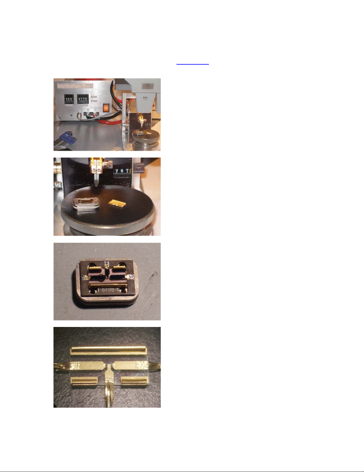
Inside the First Mixer
Photos courtesy Luis Cupido, CT1DMK, of the chip-hybrids
the 21 GHz first mixer with its substrate removed, undergoing diode replacement.
group, showing the diode carrier from
The mixer diodes themselves are almost too small to see, even in the magnified view at bottom.
Actual width of the entire substrate is approximately 15 mm.
Page 14

Parts / accessory sources
Deane Kidd (dektyr (at) comcast.net) is a retired Tektronix engineer who has extensive
experience with many of the company's instruments, and an even more-extensive collection of
parts and manuals for them. When contacting Deane to inquire about parts availability, be
prepared to give him the Tektronix part number of the desired component.
Advice from Deane and others can also be found on the TekScopes
contributions from other Tektronix veterans such as Stan Griffiths, whose work at the company
included technical marketing for the spectrum-analyzer product line.
PC board extenders are needed for many 49x/275x service and calibration tasks. High-quality
reproductions are frequently available from Norway Labs
about them.
Extenders for the keyboard and power supply assemblies were also issued by Tektronix, but they
are not included in Norway Labs's package, and appear only rarely on the surplus market. While
nice to have, they are not as important as a full set of PCB extenders.
Don't neglect eBay when searching for parts and documentation -- it should be your first resort. If
you can afford a "parts mule" -- a junked instrument whose modules are compatible with yours -by all means grab one!
; ask for Matt North when inquiring
Yahoo group. Watch for
Module swaps and upgrade possibilities
Modules can typically be exchanged between instruments of similar vintage -- 492/496,
494/492A, 494A/492B, and so on. Early-model 495s are most compatible with the 494 and 492A
models, while late-model 495s with the 10 Hz RBW feature (post-B030000) are essentially 494As
without the 829 MHz IF strip.
Along the same lines, the later 497s (post-B020000) are relabelled 494As as far as I've been able
to tell. They can be recalibrated for use up to 21 GHz.
Firmware images and notes on DIP switch settings -- invaluable for upgrading as well as
troubleshooting -- can be found in the Manuals/ROM Images section at http://www.ko4bb.com/
.
Use caution when toggling DIP switches found in these analyzers, especially the GPIB switch on
the back panel. These switches sometimes fail when actuated for the first time in 20+ years,
leading to difficult-to-diagnose problems.
Page 15

Software applications
Several measurement applications were marketed by Tektronix for the -P suffix (GPIB
programmable) analyzers in the 49x/275x line, allowing users to take screenshots, automate
basic RF measurement tasks, and control equipment located at remote sites. Beginning with the
494P, the instruments' firmware could drive pen plotters directly. However, resurrecting obsolete
Tektronix controllers and plotters is not usually worthwhile unless you're faced with the need to
recreate or support a specific measurement system. Many commonly-used spectrum analysis
applications have been recreated on modern PC operating systems.
Commercial applications that support the 49xP/275xP spectrum analyzers include PrintCapture
from F&F SoftTools and various utilities from Aphena
Plottergeist.
On the freeware side, the KE5FX GPIB Toolkit
collection of Windows applications for Tektronix, Advantest, and HP/Agilent spectrum analyzers,
including full C/C++ source code. The GPIB Toolkit includes utilities for screen capture, elapsedtime spectrum recording with "waterfall" displays, phase noise measurement, and other
applications.
, including SoftPlot, RemoteControl, and
(by the author of this document) provides a large
In short, GPIB support is a very useful feature, one that often goes unappreciated by hobbyists. If
you have a programmable spectrum analyzer that isn't connected to your PC, you're missing half
the fun!
Page 16

Recommended books and app notes
TekScope volume 12, issue 1 (1980), available in .PDF format at the http://www.ko4bb.com/
manuals page, introduces the 492 with descriptions of various production advances and key
design concepts.
The Manuals / Tektronix 49x directories contain other useful application notes as well, including
the well-regarded Fundamentals of Spectrum Analysis. As the directory layout on this site may
be subject to change over time, it's not practical to include direct links. It's very worthwhile to
explore the Manuals / Tektronix pages on your own.
Spectrum and Network Measurements
analysis. A more technically-oriented (and much harder to find) volume is Modern Spectrum
Analyzer Theory and Applications (Artech House 2nd edition, 1984) by Tektronix's Morris
Engelson. Neither of these books are oriented towards cutting-edge signal analysis technology,
but they do an outstanding job of covering topics that are relevant to users of 1980s- to 1990svintage instruments.
Other Tektronix application notes describe the use of accessories such as waveguide mixers and
tracking generators, as well as specific measurement techniques. Links to online copies of these
will be added to future versions of this document as they become available.
by Bob Witte is a great tutorial on all facets of spectrum
Page 17

Appendix: Typical phase-noise baseline plots
The traces below were acquired with PN.EXE from the GPIB Toolkit, measuring the output of a
Wenzel crystal oscillator whose phase noise is substantially lower than the analyzers' own.
Typical examples of the 494AP, 494P, and 492P spectrum analyzers were compared. Minimum
RF attenuation was set to 0 dB in all three cases, and 20 dB of carrier clipping was used.
The 494P appears noisier close to the carrier, but this is actually a consequence of its broader
30-Hz RBW specification compared to the 494AP's 10-Hz minimum bandwidth. The 30-Hz filter
skirt, and not the LO phase noise, is responsible for the observed performance at offsets below
about 300 Hz.
At offsets of 10 kHz and beyond, all 49x/275x analyzers should generally perform within +/- 5 dB
of these traces. All three analyzers meet Tektronix's rather-loose PN specifications easily.
Page 18

Appendix: Calibration program for 494P and earlier analyzers
For analyzers that don't have firmware procedures to assist with digital storage and 1st/2nd LO
calibration, here's a C version of the BASIC code from the 492P service manual (070-3783-01).
A GPIB adapter from Prologix or National Instruments will be required.
This code can be compiled with the MS Visual Studio Express package and linked with the
gpiblib.lib library provided with the KE5FX GPIB Toolkit
. Specifically, you can save the file in the
Toolkit's installation directory as cal_tek490.cpp and compile it with cl cal_tek490.cpp gpiblib.lib ,
then run cal_tek490 <addr> from the command line to display the required calibration pattern.
Replace <addr> with the analyzer's actual GPIB address.
A ready-to-run copy of this program is included in the GPIB Toolkit under the name
cal_tek490.exe.
#include <stdio.h>
#include <conio.h>
#include <assert.h>
#include <stdlib.h>
#define WIN32_LEAN_AND_MEAN
#include <windows.h>
#include "gpiblib.h"
S32 addr;
void WINAPI GPIB_error(C8 *msg, S32 ibsta, S32 iberr, S32 ibcntl)
{
printf("%s",msg);
exit(1);
}
void connect(void)
{
GPIB_connect(addr,
GPIB_error);
}
void disconnect(void)
{
GPIB_disconnect();
}
void ds_cal(void)
{
GPIB_CTYPE type = GPIB_connection_type();
if (type != GC_NI488)
{
printf("Error: This test requires a National Instruments GPIB interface -- it");
printf("will not work with Prologix adapters\n");
return;
}
C8 C[1024];
C[0] = 64;
S32 k = 125;
S32 i1 = 0;
for (S32 i=1; i <= 10; i++)
{
for (S32 j=1; j <= 100; j++)
{
C[i1+j] = k;
}
k-=25;
i1+=100;
if (!(k >= 25))
{
Page 19

k = 225;
}
}
GPIB_write("SIGSWP");
GPIB_write(C, 1001);
printf("\nPress any key when test complete... ");
getch();
printf("Done\n");
GPIB_write("INIT");
}
void cf_cal(void)
{
printf("\nConnect calibrator, then press any key when test complete... ");
GPIB_write("INIT; REF -20; SPAN 2M; SIG");
while (!kbhit())
{
GPIB_write("FREQ 100M;DEG;SIG;WAIT;");
GPIB_write("FREQ 1.8G;DEG;SIG;WAIT;");
}
getch();
printf("Done\n");
}
void lo1_sens_cal(void)
{
GPIB_write("INIT; FREQ 10M; SPAN 100K");
disconnect();
printf("\nCenter marker on screen, then press any key to continue... ");
getch();
connect();
printf("\nPress any key when test complete... ");
while (!kbhit())
{
GPIB_write("TUNE 5M;SIG;WAIT;");
GPIB_write("TUNE -5M;SIG;WAIT;");
}
getch();
printf("Done\n");
}
void lo2_range_cal(void)
{
printf("\nPress any key when test complete... ");
while (!kbhit())
{
GPIB_write("TUNE 2M;SIG;WAIT;");
GPIB_write("TUNE -2M;SIG;WAIT;");
}
getch();
printf("Done\n");
}
void lo2_sens_cal(void)
{
printf("\nPress any key when test complete... ");
while (!kbhit())
{
GPIB_write("TUNE 2K;SIG;WAIT;");
GPIB_write("TUNE -2K;SIG;WAIT;");
}
getch();
printf("Done\n");
}
Page 20

void shutdown(void)
{
GPIB_disconnect();
}
void main(S32 argc, C8 **argv)
{
printf("\nThis program assists with calibration of Tektronix 49xP/275xP-series\n");
printf("spectrum analyzers, using routines from volume 1 of the Tektronix 492P\n");
printf("service manual (070-3783-01, FEB 1984 edition).\n");
if (argc < 2)
{
printf("\nUsage: cal_tek490 <address>\n");
exit(1);
}
addr = atoi(argv[1]);
atexit(shutdown);
for (;;)
{
printf("\n 1) Digital storage calibration (page 3-70)\n"
" 2) 1st LO gain/offset (LO driver R1031, CF control R1032, page 3-51)\n"
" 3) 0 MHz\n"
" 4) 4.2 GHz (step 2c, page 3-52)\n"
" 5) 4.278 GHz\n"
" 6) 5.5 GHz (step 2c, page 3-52)\n"
" 7) 1st LO tune sensitivity (CF control R1028, page 3-55)\n"
" 8) 2nd LO tune range (CF control R4040, page 3-55)\n"
" 9) 2nd LO tune sensitivity (CF control R3040, page 3-56)\n"
" ESC) Exit\n\n"
"Choice: ");
C8 ch = getch();
if (ch == 27)
{
printf("Exit\n");
exit(0);
}
printf("%c\n",ch);
connect();
switch (ch)
{
case '1':
ds_cal();
break;
case '2':
cf_cal();
break;
case '3':
GPIB_write("FREQ 0M");
break;
case '4':
GPIB_write("FREQ 4200M");
break;
case '5':
GPIB_write("FREQ 4278M");
break;
case '6':
GPIB_write("FREQ 5500M");
break;
case '7':
lo1_sens_cal();
break;
case '8':
lo2_range_cal();
break;
case '9':
Page 21

lo2_sens_cal();
break;
}
disconnect();
}
}
If you are following the calibration procedures in the 492P manual (070-3783-01), note that the
roles of the 1st LO Offset (R1032) and 1st LO Sense (R1031) controls are reversed in steps 2(a)
and 2(b). Use R1031 to bring the two signals to the same horizontal position, and R1032 to align
the two signals at midscreen.
-end-
Page 22

 Loading...