

Page 1
r
r
I
OPERATORS
MANUAL
494/494P
SPECTRUM
PartNo.
Product
070-4418-00
Group
26
ANALYZER
i
First
Revised
Printing
NOV
OCT
1986
1983
Please
CHANGE
atthe
Check
INFORMATION
Rear
of
for
This
Manual
TiPAtronix
m..ar
ren
ro
f
I-ELLEN
A
A
Page 2
PREFACE
494/494P
Operators
This
manualisone
TEKTRONIX
lyzer.It
494/494P
the user
Our
intentisto
meaningful
that
wellaslaboratory
as
and
contentislisted
information
informationiscontained
vice
manual
Standards
Most
adapted
an
as
accordance
tions
Graphic
bologyisbasedonANSI
er's
data
version
494
and
494P
describes
Spectrum
is
knowledgeable
isina
.
and
terminology
by
IEEE
appendix.Abbreviationsinthe
with
explained
symbols
description.GPIS
conforms
the
Analyzer.These
explain
measurements
in
separate
Conventions
is in
and
ANSIY1.1-1972, with
in
parentheses
comply
to
IEEE 488-1978
ofasetofproduct
(programmable)
installation
about
frequency
operationofthe
the
canbemade
conditions.The
the
TableofContents.Programming
Programmers
inatwo-volume
Used
accordance
IEC.A
glossaryoftermsisprovided
after
with
ANSI
Y32
Y32
.14-1973
functions
manuals
Spectrum Ana-
and
operation
instructions
domain
4941494P
under
manual
manual,
with
those
documentation
exceptions
the
abbreviation
.2-1975
and
the
for
the
programmable
Standard
for
the
of
the
assume
analysis
so
adverse
organization
and
ser-
Service
standards
in
are
and
addi-
.
Logic
sym-
manufactur-
.Acopy
of
ANSI
and
tuteofElectrical
47th
Street,
.
Change/History
Change
and/or
bindislocatedatthe
INFORMATION
into
identified
of
.
Unpacking
for
Use"
additional
History
the
text
the
page
Instructions
are described
use
which
IEEE standards
and
New
York,N.Y
Information
information
information
section
information,
the
when
revision
by a
(e.g.,REV
and
Preparation
for
unpacking
follows
.
may
Electronic
.
that
back
.
with
page(s)isrevised
date
JAN
under
obtained
be
Engineers
10017
.
involves
pending
of
this
the
updated
located
1984)
.
for
and
preparing
"Preparing
manual
in
Use
'from,
the
Inc.,345
manual
manual
.
the lower
the
corrections
reprint
inaCHANGE
data,isintegrated
A
revised
the instrument
Instrument
left
page
corner
Insti-
East
and
is
for
Page 3
494/494P
Operators
PREFACE
LIST
LIST
OPERATORS
SERVICE
Section
Section
Section
Section
. .
OF
ILLUSTRATIONS
OF
TABLES
SAFETY
1
GENERAL
2
SPECIFICATION
Electrical
3
INSTALLATION
FOR
4
CONTROLS,
INDICATORS
Un-Nomenclated
Pushbutton
TABLE
. ... . . . . . .
. . . . . ... . . ... ... . . . . . .
SAFETY
SUMMARY
Product
Options
Configuration
Options
Accessories
Firmware
Readout
Introduction
USE
Introduction
Unpacking
Power
Requirements
Repackaging
Storage..
Introduction
Shift
Functions
Instrument
Crt
Controls..
Sweep
Display
General
494P
(GPIB)
Front-Panel
Rear-Panel
Operational
Service
. . ... . ... . ... . . .
. ... . ... . . ... . _ .
SUMMARY
. ... . ... . . . . . ... .
INFORMATION
Overview
for
Power
. ...
. . . . ... . ... . ... . ... . ...
. . . . . ... . . . . ... . .
Version
. . ...
... . . . . . ... . ...
. . .
. . ...
Characteristics.. .
AND
. . . .
and
Initial
Source
or
Parameters
Purpose
Related
and
. . . ... . ... . . . . . .
for
Shipment
. ... . . . ...
CONNECTORS,
. . . . ... .
of
Power
.
. ... .
Scan
. . ... ... . ... . ...
Pushbuttons
Controls
Input/Output
Input/Output
Front
Functions
Functions..
Functions
OF
Page
. . ...
. .
.
.
.
. . .
.
... . .
.
. ... . ... . ... . .
Cord
. . . . . . ... . ... .
and
Error
. ...
.
PREPARATION
. . ... . . ... . . . . ..3-1
Inspection
Power
. .
. . . . . .
AND
... . . . . . .
the
Pushbuttons
Control
.
... . ... .
. . . . . . . ... .
... . ... . . . . ..4-3
. . . ... . . . . .
Connectors
Connectors
Panel
. . . . . . . . ... . .
. . . .
.
. . . . ...
,
. . .
.
.
Message
.
. . . . . ...
. . . ... .
. .
.
.
. . ...
.
. . . .
,
.
. . . .
. ....4-12
. .
.
.
.
.
.
4-12
4-12
1-1
1-1
1-1
1-1
1-3
2-1
2-1
3-1
3-1
3-2
3-3
4-1
4-1
4-1
4-2
4-2
4-9
4-9
4-10
4-10
CONTENTS
i
Section
iv
iv
v
vii
Section
6
5
TURN-ON
OPERATIONAL
Firmware
Readout.. . ... . ... . .
Firmware
Error
Turn
Use
FunctionalorOperational
Equipment
Preliminary
2.Check
3.Check
4.Check
5.Check
6.Check
7
8.Check
9
10.GPIB
GENERAL
Firmware
Readout
Using
Crt
Intensity
Signal
Resolution
Span,
Using
AUTO
Using
Using
Time
PROCEDURE
Version
Version
Message
On
Procedure
. . .
.
. . . . . . . . . . . . . . . ... . . .
1.Initial
2
.
1.Check
.
.
Light
Turn
Calibrate
Reference
Range
Pushbuttons
Resolution
Linearity.. . . ... .
and
RF
Check
Check
Stability
the
Domain
.
Required.. . . ... .
Preparation
OperationofFront Panel
Gain
Counter
Span
Resolution
Shape
Reference
Attenuator
Sensitivity..
Residual
Frequency
Verification
OPERATING
Version
. . . .
the
Help
Filters
Level
Application
Bandwidth,
and
Sweep
the
MANUAL
PEAK
the Signal
Video
AND
CHECK
and
Error
Message
.
. . ...
. . . . ...
. . . . . . . ... . . . .
Readout
and
On
Center
Level,
.
. . . . . . . ... . . . . ... .
and
Variation
Bandwidths
Accuracy
Factor
. ... . .
and
. . . . . . . . . . ... . .
Feature
... . . . . . . . . . . . ..6-1
and
Time
Mode
Identifier
Filters
Operation
. . . . . .
Preparation
. . . . . ... ... . .
Frequency,
and
Dynamic
Check..
.
. . . .
. ... . .
Controls
Between
. . ... . .
Accuracy..
and
. . . . . . . . . . .
Bandwidth
. ... . . . . . . .
Level
Gain
Steps
. ...
. . . . .
. . . ... . . . .
FM
. . . . ... . . .
Drift
or
.
. . ..... . . ...
Program
PROCEDURE
Error
. . . . . . . . ..6-1
Beam
.
. . ... . . . . . . . .
Frequency
. . ... . . ...
PEAK
. .
.
. . . ... ... .
...
.
Message
Alignment
Control
. . . . . . . .
. . . . ...
. . . . ... ..6-5
Page
5-1
.
5-1
. , .
.
5-1
for
. . .
5-1
.
5-1
5-2
. ...
5-3
. . ..5-3
5-3
... .
5-3
5-9
. ..5-10
5-10
5-10
and
5-10
5-11
5-13
5-14
5-14
. .
.
. ..6-1
6-1
6-1
6-2
or
6-3
6-3
6-4
REV
MAY
1984
Page 4
4941494P
Operators
Section
6
TABLE
GENERAL
(cant)
Triggering
Sweeping
Manual Scan
Reference
Vertical
JA
Using
Mode.. . . . . . . ... . . ... ... . . . . .
Digital
Store/Recall
Using
Using
Feature..
Un-Nomenclated
Pushbutton
External
Reference
Conversion
Handling.. . . . ... .
Installation..
Operation
494P
Connectors
GPIB
RESET
ADDRESSED
PLOT..
Setting
Switches
Talk/Listen-Only
TALK
Switches
Data
Restoring
Display
OPERATING
the
Display
the
Display
the
of
Level,RFAttenuation,
Display
Mode
Min
Storage
the
Counter
the
Automatic
Mixers
GPIB
Controls,
.
Function
TO
. ... ..... . . . . . . . . ... .
the
ONLY,
Logging
Control
. . ... ... . . . . . . . . . . ... ..6-15
.
. .....
. ... ... ..... ... ... . . .
Noise or
. ... . . . . . ... . . . . .
Feature
. ...
. . . ... ... ... . . . .
Front
Functions
and
Level
Readout
Loss
for
. . . . . . . ... . . . . ... .
. ... . ..... .
.
. ... ..... . . . ... . . ...
Readout
LOCAL
...
GPIB
ADDRESS
. . . . ... . . ... ... . . . . . .
Operation
LISTEN
. . . . . . . ... . . . . . ..... .
. . ..... . . . . . .
Settings
OF
PROCEDURE
. . . . . . . . . ..6-5
. . . . . . . . . ..6-5 Operational
Spectrum
. . . ... . . .
Min
Distortion
. ... ... . . . . .
. ... ... ... . ...
Calibration
Panel
. ... . . ... . .
Diplexer
and
External
. ... ... . . . . ..6-10
...
Indicators,
.
. . . . .
(REMOTE)
. ... ...
. .
. . . . . ..6-13
ONLY
and
. . ..6-5
. . . .
Mixers
.
. . . . . .
and
, ...
... . .
. . .,.
the
CONTENTS
Page
Section
and
6-6
6-6
...
6-6
6-7
6-8
6-8
6-8
6-8
.
6-9
6-9
6-10
6-11
6-11
6-11
6-11
6-12
.
6-12
6-13
6-13
6-14
Section
Appendix
(cont)
6
GENERAL,
{cont)
Connectingtoa
494/494P
Service
Product
7
OPTIONS
Option08. . . . . . . . . . . . ... . . ... . . . .
Option
Option13. ... . . . . . . . . ... . . . . . . . . .
Option14. ... . . ... ... . ..... . . . . . .
Option20. ... . . ... ... . ..... . . . . . .
Option
Option22. . . . . . ... ...
Options
(Rackmount/Benchtop
Option30. . ..... ... ... ... . . . . . . . .
Option31. . ..... . . ... . ... . . . . . . . .
Option32.
Options
Characteristics
Safety
Accessories
Option41... ..... ... . . ...
Option52. . . ..... ... . ... . . . . . ... .
A
GLOSSARY
General
Terms
Terms
Terms
Spectrum
OPERATING
Precautions
. ... . . . . . ... ... . . . . . . . . .
Manual
Service
12
. ... . . . . . . . . ... . . . . . . . . .
21
. ... . . ... ... . ..... . . . . . .
30,
31,
and
. ... . . . . . . . . ... . . . . . . . .
31,
30,
and
. . . . . . . ..... .
Requirements
. . . . . . . . . ... . . . ... .
Terms
RelatedtoFrequency.... . .
RelatedtoAmplitude.... . .
Related
Analyzers.. ... ..... . .
PROCEDURE
System
. . . . . ...
. ... . ..... . . . . . .
32
32
. . . . . . ... ... .
to
Digital
. . ... ... .
for
the
. . . . . . . . .
. ..... . . . . . .
Versions)
Environmental
. . ...
Storage
. . . ...
. . . . . .
.
. . . . . .
. . . . ... .
. . . . .
for
Page
6-16
6-16
6-17
6-17
7-2
7-2
7-2
7-2
7-2
7-3
7-3
7-4
7-4
7-4
7-4
7-4
7-6
7-6
7-6
7-6
A-1
A-1
A-2
A-3
Page 5
494/494P
Fig
.
No
.
2-1
2-2
3-1
4-1
4-2
5-1
5-2
5-3
5-4
5-5
5-6
6-1
6-2
Operators
494/494P
Probe
Dimensions
International
(Option
Front
connectors
Rear
Crt
Typical
SPAN
Integrating
Using
response.. .
Displays
shape
Typical
residual
Volts/dBm-Watts
impedance
Circuit
coupled)
Spectrum
power
power
A1-A5)
panel
selectors,
. . . . ... .
panel
connectors
display
and
display
position
a
display
IDENT
feature
that
factor
are
display
FM.. .
. . ... . .
ofa75to50S2matching
. . ... . . . .
LIST
Analyzer.. . . . . ... . .
connector
.
. . ... .
for
readout
of
calibration
. . . . . . ...
... ... . . . . ... ...
illustrate
determined..
showing
. . . ._. . ... ... . .
conversion
.
.
. .
... . . . . ...
. .
. . . . . .
cord
configuration
4941494P
controls,
.
. ... . . ... . . . . .
on the
for
power-up
markers
. . . . . . . . . ... . .
with
the
Video
to
identifyareal
how
bandwidth
howtodetermine
chart
. . ... . . . ...
... . . . . . . . . . . . ... .
OF
.,... . . ...
.
. . . . ... . . .
and
494/494P..
Filter.5-5
. . . . . ...
... ..... ..5-11
.
for50SZ
. . . . . .
pad
(ac
.
state
in
MAX
or
true
and
. . ... .
..6-2
ILLUSTRATIONS
Page
..2-12
. .
.
6-3
No
viii
2-14
3-2
4-2 6-6
4-11
5-1
5-2
5-6
5-14
6-3
6-4
6-5
6-7
6-8
6-9
6-10
6-11
6-12
6-13
6-14
7-1
Fig
.
.
Graph
d6m,
included
Typical
waveguide
Identifier
Integrating
UsingB-SAVE
between
Diagram
installation.. . . . . ... . ... ... . . ... . .
Typical
GPIB
494P..
StatusofGPIB
GPIB
TEKTRONIX
Drive
Controls on
to
International
configuration
to
d6mV
display
display
selectors
ADDRESS
in
a
the
Talk/Listen
illustrate
where
mixer
mode
the
SAVEAandBdisplays
showing
. . . ... ... . ... . . . . .
Talk/Listen
the
the
and
c1BjuV
necessary)
generatedbya
. ... . ... ... . ...
displays
display
from
as
4924
4924
power
for
A
to
external
and
shown
switch
Digital
Only
cord
the
with
observe
an
indicators
Only
and
transfers
494/494P
relationship
(matching
. . . . ... .
waveguide
external
on
on
the
Cartridge
system
494P
and
attenuator
. . ... . .
signal
. ... ... .
the
Video
the
differential
.
mixer
unique
.
. . . . . . . . .
the
crt
readout6-12
rear
. . ... . .6-14
that
.
. . . . . . . .6-15
plug
. . . . ... . .
Page
between
... ...
into
.
. .
Filter6-5
. . . . ...6-7
mixer
to
panel
Tape
are
6-3
the
6-4
6-4
. . .
6-9
. . . .6-11
the
6-12
.6-13
used
.7-1
Table
No
1-1
1-2
2-1
2-2
2-3
2-4
2-5
2-6
2-7
2-8
2-9
2-10
iv
.
Standard
Tektronix
Mixers
Frequency
IF
Number
Amplitude
Sensitivity..
Input
Output
General
Power
Environmental
Physical
Accessories.. . . . . . . . . . . . ... .
High
. . .
.
Related
Frequency,
(N)..
Related
Signal
Characteristics
Signal
Characteristics
Requirements
Characteristics
Performance
. . . . . . . . . . .
Characteristics
LO
Range,
. . . . . ...
Characteristics
. ... . ...
Characteristics....
Characteristics
Waveguide
. .
.
.
and
. . . ... . . . .
. . . ... . . . . . . . .
.
. ....... . . . . .
. . . . ... ... .,.
. . . . . ... . . .
LIST
... ... . . . .
. ... . ..2-1
Harmonic
.
. . . .
. . . . . ... . ..2-9
. .
. ... ... . . ..2-12
OF
Page
... . .
..2-5
.
.
. .
...
.
. .
. ... .
. . ..2-14
1-2
1-2
2-5 7-2
2-8
2-10
2-11
2-12 7-6
TABLES
Table
No
.
2-11
3-1
5-1
7-1
7-3
7-4
7-5
494/494P
Requirement
Shipping
494/494P
Power
Option
Mixers)
Option21(WM
Option22(WM
Options
Characteristics
Options
Characteristics.. . ... . . . ... .
Safety
Carton
Sensitivity
Cord
20
(General
Characteristics
30, 31,
30, 31,
Standard
Conformance
Test
Options
Purpose
490-2)
490-3)
&32Environmental
. . ... ... _
&32Physical
and
Regulatory
. . . . . . . .
Strength
. . . . . . . . . . ... . ... .
. .
.
. . . . ... . ... . . . .
Waveguide
. .
... . . . . . ... . . .
Characteristics
Characteristics
. . . . .
... . .
. . . . . ... ..3-3
.
. . .
. . ..7-3
. . . . ....7-5
... . ... .
. .
Page
2-15
5-13
7-1
7-2
7-3
7-5
Page 6

494(494P
Operators
The
informationinthis
operating
cautions
apply,
willbefound
but
CONFORMANCE
494/494P
The
Standards
Safety
Safety
CSA--Electrical
FM-Electrical
ANSI
and
Instrumentation
IEC
Electronic
Regulatory
VDE
0871
High
Frequency
and
servicing
may
not
and
Utilization
039
Electronic
348
(2nd
Requirements
Class
OPERATORS
safety
personnel.Specific
throughout
appearinthis
STANDARDS
complies
Regulatory
Bulletin
Standard
.5-Safety
Measuring
.
addition)-Safety
Measuring Apparatus
B-Regulations
Apparatus
summary
the
summary
TO
INDUSTRY
with
the
Requirements
Requirements
for
and
Installations
warnings
manual
.
following
Class
3820
and
Requirements
.
RFI
Suppression
is
for
where
Industry
:
for
Electrical
Controlling
.
SAFETY
both
and
they
for
of
Power
that
conductorsorbetween
A
conductorinthe
SUMMARY
DANGER
accessibleasone
In
This
Marked
As
0
This
will
protective
indicatesapersonal
Manual
This
cautionaryorother
on
DANGER
Protective
ATTENTION
Source
productisintended
not
apply
ground
reads
SYMBOLS
symbol
Equipment
-
ground
more
either
connection
power
cordisessential
the
High
-
POWER
than
injury
hazard
marking
indicates
refer
to
250Vrms
supply
.
where
informationistobefound
voltage
(earth)
operate
.
terminal
to
manual
fromapower
conductor
by
way
.
between
of
the
for
safe
.
immediately
applicable
source
the supply
and
ground
grounding
operation
.
.
.
In
This
CAUTION
that
could
property
WARNING
that
could
As Marked
CAUTION
ately
accessible
property,
Manual
statements
resultindamage
.
statements
result
in
on
Equipment
indicates
as
including
TERMS
personal
a
personal
one
reads
the
equipment
identify
identify
conditions
to
the
equipment
conditionsorpractices
injuryorlossoflife
injury
hazard
the marking, orahazard
itself
.
or
practices
.
not
or
other
immedi-
to
Grounding
This
torofthe
power
cord
ingitto
ground
power
Danger
sible
may
Use
product
connectionbywayofthe
cordisessential
Upon
conductive
appeartobe
the
Use
only
the
Product
productisgrounded
power
the
From
lassofthe
Proper
.
cord.To
intoaproperly
product
the
inputoroutput
for
Loss
of
protective-ground
(including
parts
insulating)
Power
cord
power
through
avoid
wired
safe
Ground
can
Cord
and
the
grounding
electrical
receptacle
grounding
operation
knobs
renderanelectric
connector
shock,
before
terminals.A
conductorinthe
.
connection,
controls
and
specified
conduc-
plug the
connect-
protective
all
acces-
that
shock
.
for
your
Page 7
494/494P
Use
For
see
Refer
personnel
Use
To
only
rating
Volume2of
fuse
Operators
onlyapower
detailed
Figure
the
avoid
the
(as
replacementtoqualified
informationonpower
t-3
.
cord
and
.
Proper
fuseofcorrect
specifiedinthe
fire
the
Fuse
hazard or
Service
cord
that
connector
type,
Replaceable
manual)
is in
changes
damage
voltage
service
good
condition
cords
to
qualified
to
the equipment,
rating,
E=lectrical
for
your
personnel,
and
connectors,
and
Parts
product
.
service
current
list
.
Refer
use
in
OPERATIONAL
Do
Not
Operate
To prevent
an
explosive
tified
for
such
Do
Not
Remove
To
avoid personal
ersorpanels
ers
and
panels
in
Explosive
explosion,donot
an
atmosphere
operation
.Donot operate
properly
unlessithas
.
Covers
injury,donot
installed
PRECAUTIONS
Atmosphere
operate
or
Panels
remove
the product without the
.
been
the
this
specifically
product
product
covcov-
in
cer-
Page 8

494/494P
Operators
Do
Not
Do
not
product
and
resuscitation
Use
Care
Dangerous
uct.To
tions
avoid
and
Service
perform
unless
another
When
voltages
personal
components
FOR
Refer
Alone
internal
person
is
present
Servicing
existatseveral
injury,donot
while
SERVICE
QUALIFIED
alsotothe
serviceoradjustment
capableofrendering
.
With
power
Power
touch
ison.
On
pointsinthis
exposed
Disconnect
SAFETY
SERVICE
preceding
of
this
first
aid
prod-
connec-
power
SUMMARY
PERSONNEL
Operators
before
components
Power
This
that
will
conductorsorbetween
A
protective
torinthe
Safety
removing
.
Source
product
not
apply
ground
power
protective
is
intendedtooperate
more
cord,isessential for
ONLY
Summary
panels,
than
250
either
supply
connection,
soldering,orreplacing
fromapower
V
rms
conductor
via
the
safe
between
grounding
the
and ground
conduc-
operation
source
supply
.
.
Page 9
494/494P
Operators
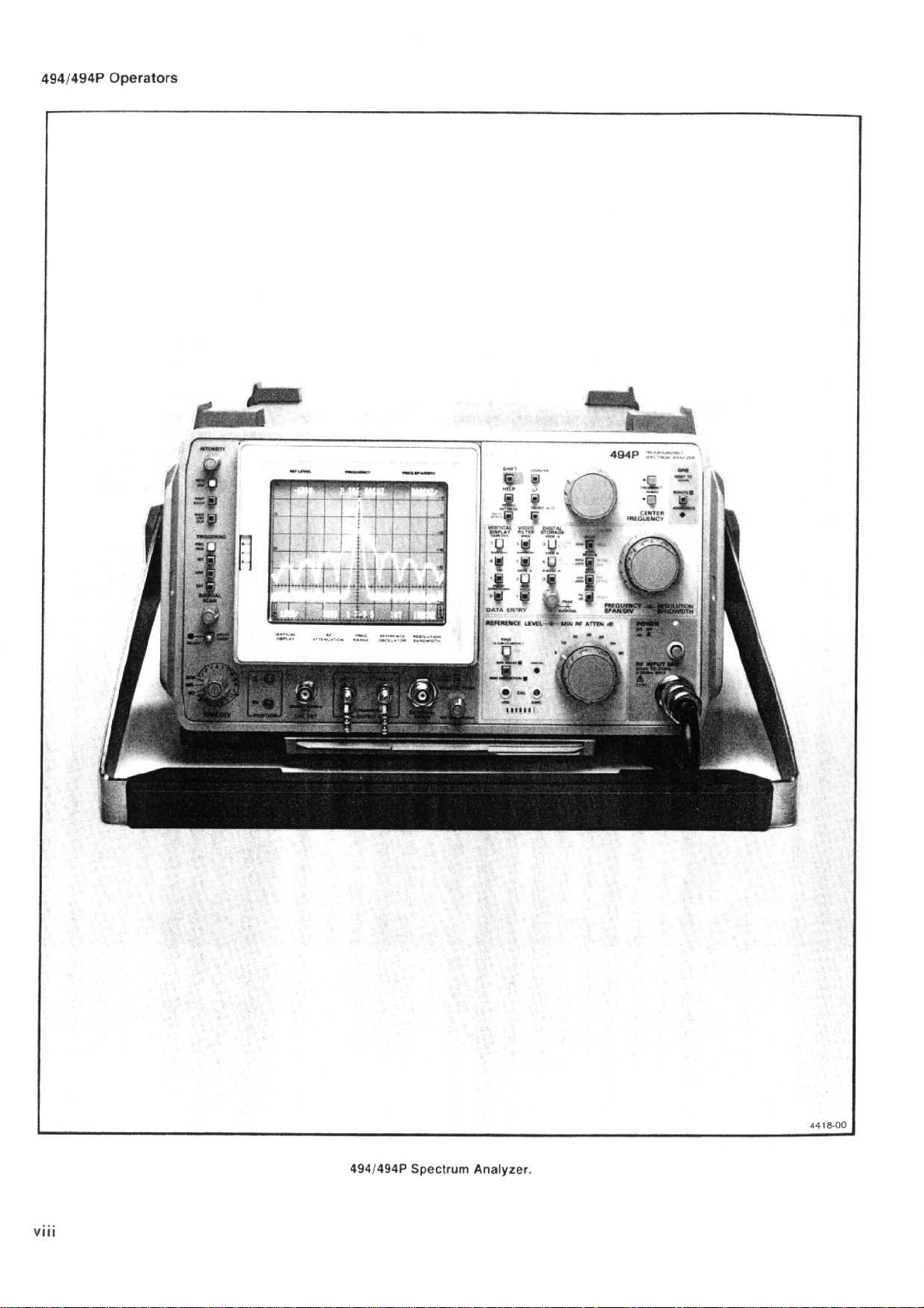
Viii
4941494P
Spectrum
Analyzer
.
Page 10
Section
1-4941494P
Operators
Product
high
Microcomputer
hances
quency
ability,
storage
settings
scribes
along
The
nal mixer,
guide
withaminimum
resolution
racy
tions
to
compare
addition to
nine
be
storedinnon-volatile
ditional
panel
Center
panel
keyboard.When
alter
lected.Other
ence
previously
Counter
In
time
quency
After
time.Display
ence
selectable
(amplitude)
the
spondtothe
tion
is-121
21
GHz
Overview
494 and
The
performance,
operation.Its
accuracy
precise
display,
and
function of
with
messages
frequency
and
mixers.A
thatiscommensurate
Digital
.
such as
separate
analysis
control
frequency
tuning
the
Span/Div
level,
may
accuracyto1
addition,
for
stable
driftisless
one
hour,itis
level
steps
mode.When
Data
Entry
in
Section6).
dBm
.
control
amplitude
displays,
upto325
storage provides
SAVE
and
subtract
the
conventional
displays
setups
knob
parameters,
alsobekeyboard
available
the
operation
dynamic
readout
from1to15dB,
keyboard,
display
to7.1
GENERAL
the
494P
programmable
compact,
and
non-volatile
the
that
range
minimum
spanof50
A,B-SAVE
and
comparison.Uptoten
can
may
or
using the
setting
only
494/494P
than
less
range
from
mode
Sensitivityat30
portable
most
of
main
stability,
and
front
is
displays,
with
memory,
directly
Hz
500
the
GHz,
functions
features
measurement
memory
crt
message
panel
explain
10
kHz
GHz
when
resolution
Hzldlv,
flicker
digital
their
alsobestored
be
selectedbymeansofthe
selected
keyboard,itis
regardlessofthe
suchasvertical
under
resolutionisavailable
requires
.In15
Hz
per minuteofsweep
than
50 Hz
80
is
-117
vertical
the
reference
(see
General
decreasing
instruments are
spectrum
simplifies
are;synthesizer
precision
controls
operating
to 21
provides
with
free
MAX
A,
save
storage
parameter
then
selected
GPIB
minutes
dB,
dBm
and0.25
displayisselected
Hz
signal
capability,
retain
to
readout
and
errors
GHz
with
using
external
bandwidth
measurement
the
frequency
displays
HOLD
maximum
feature,upto
readouts,
later
recalled
different
for
future
by the
not
necessary
frequency
display
with
program
onlyashort
or less
per
minute
with
calibrated
to
A-30
foradelta
dB
level
steps
Operating
resolution
to-96
analyzers
and
counting
front
that
selectors
.
the
of30Hz,
plus
with
values
for
recall
Data
and
the
flexibility
control
.
warm-up
the
sweep
of
dBm,
informa-
bandwidth
dBm
INFORMATION
The
494P
featuresofthe
those
intended
tobeused
operation
rackmount
Analyzeristhe
inastandard
cabling
1st
provides
rear
benchtop
feetonthe
benchtop
cooling.This
applying
For
approved
are
listed
.
for
of
.
such
1-2
the
operated
LO,
panel
the
as
en-
fre-
digital
panel
de-
inter-
wave-
accu-
func-
which
.
In
can
ad-
front-
.
front-
Entry
to
se-
refer-
fre-
time
refer-
in
A
with
corre-
at
instrument
cept
.
be remotely
the
494P
lers.This
mers manual
The
Spectrum
to
mount
semi-rigid
INPUT,
This
cabinet
The
rackmount
the
els
and
and
ditional
before
Options
Tektronix
tionally
These
manual
Options
.
Options
section
versions
.
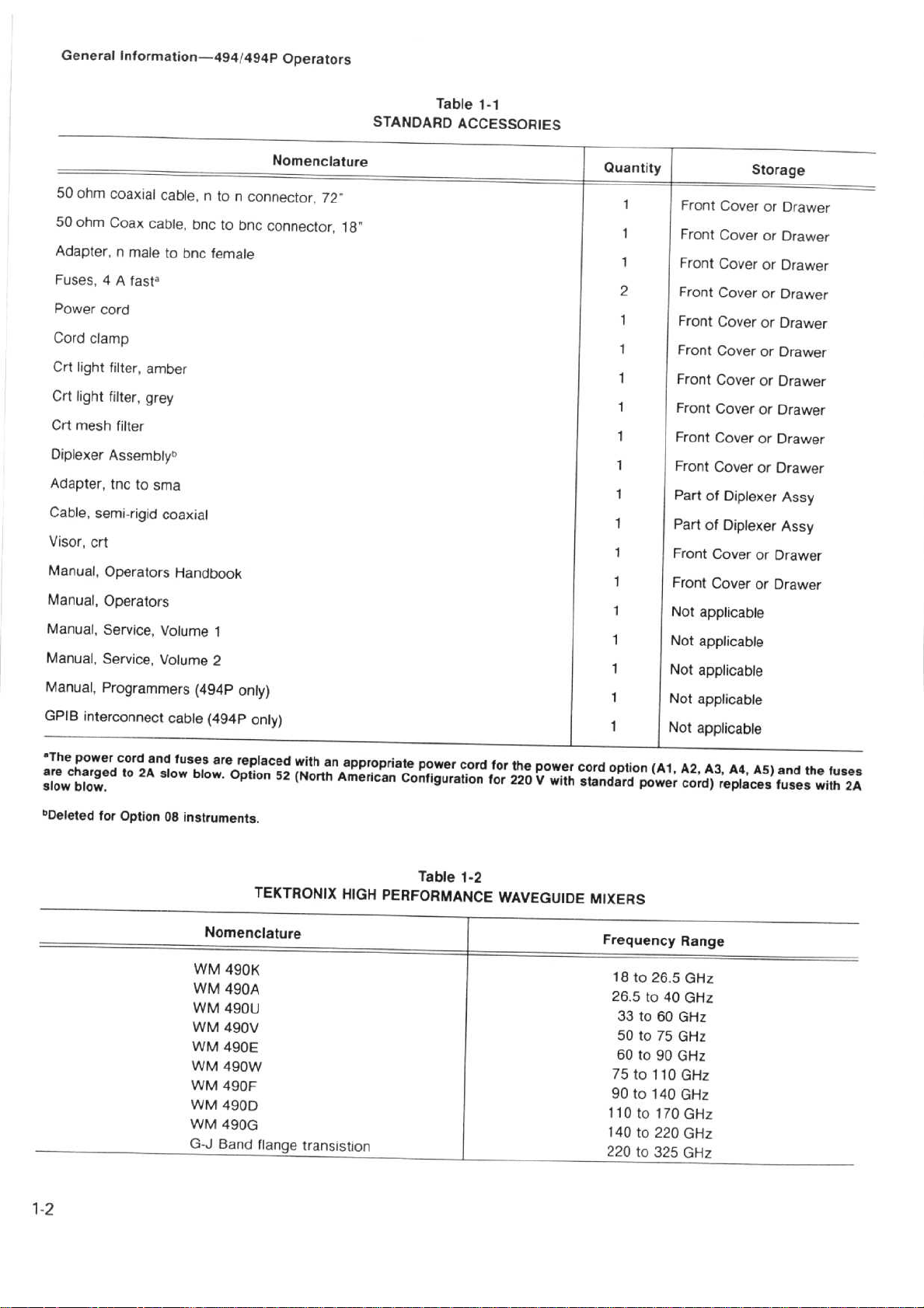
Accessories
Standard
are
listedinTable
sories
etc.Table
available.Standard
listedinVolume2of
Replaceable
suchascables
throughout
adds
remote
for
local
through
with
describedindetailin-
is
.
version
from
the
2nd
L0,
access
version cabinet
cabinets
Power
has
the
accessories
;
Mechanical
manual
to
.
version
bottom
includealarger
fan
powertothe
Cord
implemented
power
illustratedinthe
and
494/494P
manuals
1-1,Inaddition
waveguide
lists
Tektronix
accessories,
the
adapters
and
andinthe
control
494.The
a
instrument
19-inch
etc.)to
all
(Option
must
capabilitytothe
front-paned controls
use,
suchasINTENSITY)
the
GPIB
varietyofsystems
(Option 30)
inacabinet
rack.Option
panel
front
the
front-panel
32)isthe
with
the
the
cabinet.Both
of
be
installed
instrument
Configuration
options
cord
and
Options
describedinthe
are
including
that
come
with
there
mixer
sets,
Tracking Generators,
waveguide
with part
service
Parts
instructions,
list.Optional
are
listed,
Tektronix
standard
(ex-
can
which
port,
the
of
connectors(e.g.,RP
back
of
connectors
494or494P
addition
(external)
and
.
that
provide
plug
configurations
sectionofthis
mountlbenchtop
rack
each
are
optional
mixers
numbers,
where
catalog
allows
and
control-
the
Program-
494/494P
designed
31
includes
the
cabinet
via
of side
following
accessories
appropriate,
pan-
rackmount
fan
for
operating
interna-
Options
instrument
acces-
that
.
are
are
the
.
the
in
ad-
.
REV
MAR
1984
Page 11
General
50
ohm
50
ohm
Adapter,
Fuses,
Power
Cord
Crt
light
Crt
light
Crt
mesh
Diplexer
Adapter,
Cable,
Visor,
Manual,
Manual,
Manual,
Manual,
Manual,
GPIB
Information-494/494P
coaxial
Coax
4
cable,nto
cable,
n
maletobnc
A
fasta
cord
clamp
filter,
amber
filter,
grey
filter
Assembly
tnc
semi-rigid
to
,
sma
coaxial
crt
Operators
Operators
Service,
Service,
Volume
Volume
Programmers
interconnect
cable
bnctobnc
female
Handbook
1
2
(494P
(494P
n
connector,
connector,
only)
only)
Operators
72
18"
STANDARD
Table
ACCESSORIES
1-1
Front
Cover
Front
Cover
Front
Cover
Front
Cover
Front
Cover
Front
Cover
Front
CoverorDrawer
Front
Cover
Front
Cover
Front
Cover
Part of
Diplexer
PartofDiplexer
Front
Cover
or
Front
Cover
or
Not
applicable
Not
applicable
Not
applicable
Not
applicable
Not
applicable
or
or
or
or
or
or
or
or
or
Drawer
Drawer
Drawer
Drawer
Drawer
Drawer
Drawer
Drawer
Drawer
Assy
Assy
Drawer
Drawer
"The
are
charged
slow
4
Deleted
power
brow
.
for
cord
to
Option
and
2A
fuses
slow
blow
08
instruments
WM
WM490A
WM
WM
WM
WM
WM
WM
WM490G
G-J
are
replaced
.
Option
52
.
TEKTRONIX
Nomenclature
490K
490U
490V
490E
490W
490F
490D
Band
flange
with
an
(North
appropriate
American
HIGH
transistion
power
Configuration
Table
PERFORMANCE
cord
1-2
for
the
for
220Vwith
WAVEGUIDE
power
cord
option
standard
MIXERS
Frequency
18
26.5to
33to60
50to75
60
75to110
90to140
110
140to220
220
(Al,
power
to
26.5GHz
40
to90GHz
to
170
to
325
A2, A3, A4,
cord)
replaces
Range
GHz
GHz
GHz
GHz
GHz
GHz
GHz
GHz
A5)
and
fuses
the
with
fuses
2A
Page 12

General
Information-494/494P
Operators
Firmware
This
firmware
initial
power-up
screen
Electrical
the
ware
for
ROM's
version
Version
featureofthe
version
Parts
when
cycle,
approximately
list
section,
and
their
.
and
Error
494/494P
the
power
the
two
under
Tektronix
Message
provides
on/offiscycled.During
firmware
seconds.The
Memory
part
number
Readout
readoutofthe
version
Board
flashes
Replaceable
(A54),
for
each
on
lists
firm-
An
additional
microcomputer
error
message
the
error(i.e.,failedtocomplete
featureiserror
failstocomplete
will
flash
on screen
message
any
routineorfunction,
explaining
phase
lock)
readout
the
.
.
If
nature
the
an
of
Page 13

Page 14
Introduction
This
section
safety
and
characteristics
includes
electrical,
of this
SPECIFICATION
physical,
instrument.Changes
environmental,
to
specification,
this
section
.
Section
duetooptions are
2-49414194P
listedinthe
Operators
Options
following
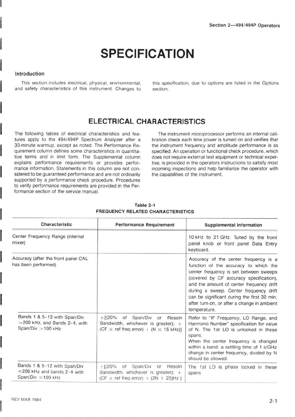
The
tures
applytothe
30-minute
quirement
tive
explains
mance
sideredtobe
supportedbya
to
verify
formance
Center
mixer)
Accuracy
has
been
Bands1&
X200
Span/Div>100
Bands
`200
SpanlDiv~_10
warmup,
cofumn
terms
performance
information.Statementsinthis
performance
sectionofthe
Frequency
(after
performed)
kHz,
1&5-12
kHz
tablesofelectrical
494/494P
exceptasnoted.The
defines
in
and
guaranteed
performance
Characteristic
Range
the
front
5-12
with
and
Bands
kHz
with
and
bands
0kHz
some
limit
form.The
requirements
performance
requirements
service
(internal
panel
Span/Div
2-4,
SpanIDiv
2-4
ELECTRICAL
characteristics
Spectrum
characteristics
Supplemental
check
procedure.Procedures
are
manual
CAL
with
with
Analyzer
Performance
or
provides
column
and
are
provided
.
FREQUENCY
[(20%
Bandwidth,
(CFXref
"
x(20%
Bandwidth,
(CFXref
CHARACTERISTICS
and
fea-
after
a
Re-
in
quantita-
column
perfor-
are
not
con-
not
ordinarily
in
the
Per-
Table
RELATED
Performance Requirement
of
Span/Div
whichever
freq
error)+(N
of
Span/Div
whicheverisgreater)
freq
error)i(2N +
The
bration
the
instrument
specified.An
does
tise,isprovidedinthe
incoming
the
capabilitiesofthe
2-1
CHARACTERISTICS
or
is
greater)
X
or
instrument
check
not
require
inspections
Resoln
;
15 kHz)] ofN.
Resoln
;
25)Hz
microprocessor
time
each
frequency
operation
external
10
kHz
panel
keyboard
Accuracy
functionofthe
center
(covered
and
during
canbesignificant
after
temperature.
Referto"IF
Harmonic
-+-
spans
When
withinaband,asettling
changeincenter
shouldbeallowed
The
f
spans
performsaninternal
poweristurnedonand
and
amplitude
or functional
test
operators
and
help
instrument
Supplemental
to21GHz.Tuned
knob
.
of
frequencyisset
by
the
amount
a
sweep.Center
turn-on,orafterachangeinambient
Number"
The
.
the
center
1st
LO
check
equipmentortechnical
instructionstosatisfy
familiarize
.
Information
or
front
panel
the
center
accuracy
CF
accuracy
of
center
during
Frequency,
specification
1st
LO
is
unlocked
frequencyischanged
frequency,
.
is
phase
verifies
performanceisas
procedure,
the
operator
by
frequency
do
between
specification),
frequency
frequency
the
LO
timeof1
divided
locked
which
exper-
most
the
front
Data
Entry
is
which
sweeps
drift
first30min
Range,
for
value
in
these
s/GHz
by N
in
these
cali-
that
with
a
the
drift
.
and
REV
MAR
1984
Page 15
Specification-494/494P
Operators
Table
2-1 (cont)
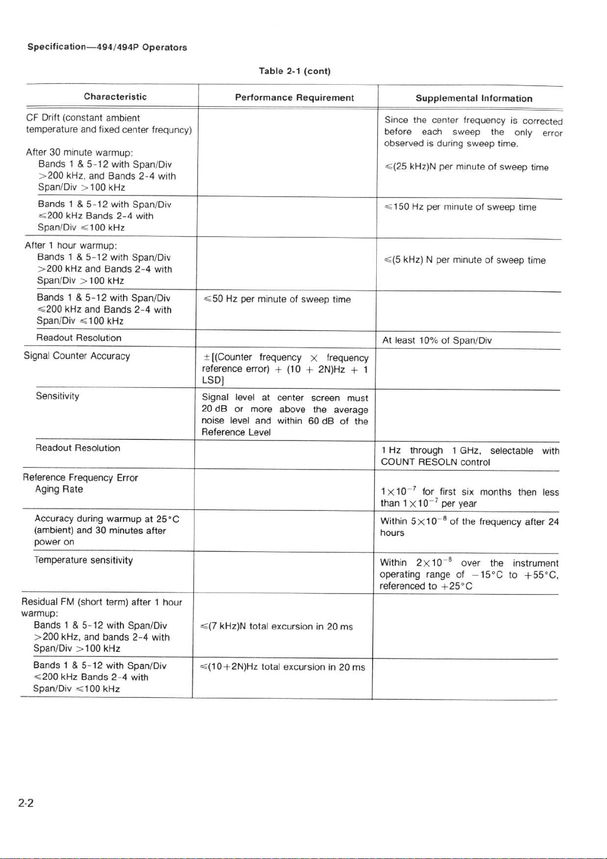
Drift
CF
temperature
After30minute
After1hour
Signal
Reference
(constant
Bands1&
X200
kHz,
Span/Div
Bands1&
--200
kHz
Span/Div--100
Bands1&
X200
kHz
Span/Div
Bands
1
&
_200
kHz
Span/Div
Readout
Sensitivity
Readout
Aging
Accuracy
(ambient)
power
Resolution
Counter
Resolution
Frequency
Rate
on
Characteristic
ambient
and
fixed
center
warmup
5-12
and
>
100
5-12
Bands
warmup
5-12
and
X100
5-12
and
--
100
Accuracy
during
and30minutes
with
Bands
kHz
with
2-4
kHz
:
with
Bands
kHz
with
Bands
kHz
Error
warmup
:
Span/Div
Span/Div
Span/Div
Span/Div
2-4
with
2-4
2-4
at
after
frequncy)
with
with
with
25°C
Performance Requirement
--50Hzper
+[(Counter
reference
LSD]
Signal
20
noise
Reference
dB
level
or
level
minuteofsweep
frequency
error)+(10+2N)Hz
at
center
more
above
and
within
Level
X
screen
the
60
dB
time
frequency
+
must
average
of
the
Since
the center
before
observedisduring
--(25
kHz)N
X150
Hz
_(5
kHz)Nper minuteofsweep
At
least
1
1
Hz
through1GHz,
COUNT
1X10⁻⁷
than
1
X10-7per year
Within
5X10eof
hours
Supplemental
frequency
each
sweep
sweep
per minute
per minuteofsweep
10%
of
Span/Div
RESOLN
for
first
control
six
the
frequency
Information
is
the
only
time,
of
sweep
time
selectable
months
then
corrected
error
time
time
with
less
after
24
Temperature
ResidualFM(short
warmup
:
Bands1&
X200
Span/Div
Bands1&
_200
Span/Div--100
kHz,
kHz
sensitivity
5-12
and
>
100
5-12
Bands
term)
with
bands
kHz
with
2-4
kHz
after1hour
Span/Div
2-4
with
Span/Div
with
--(7
kHz)N
--(10+2N)Hz
total
total
excursion
excursionin20
in
20
ms
ms
Within
operating
referen
cedto+25°C
2X10
range
-8
over
of
the
-151C
instrument
to
+550C,
Page 16
Table
2-1
(cont)
Specification-494/494P
Operators
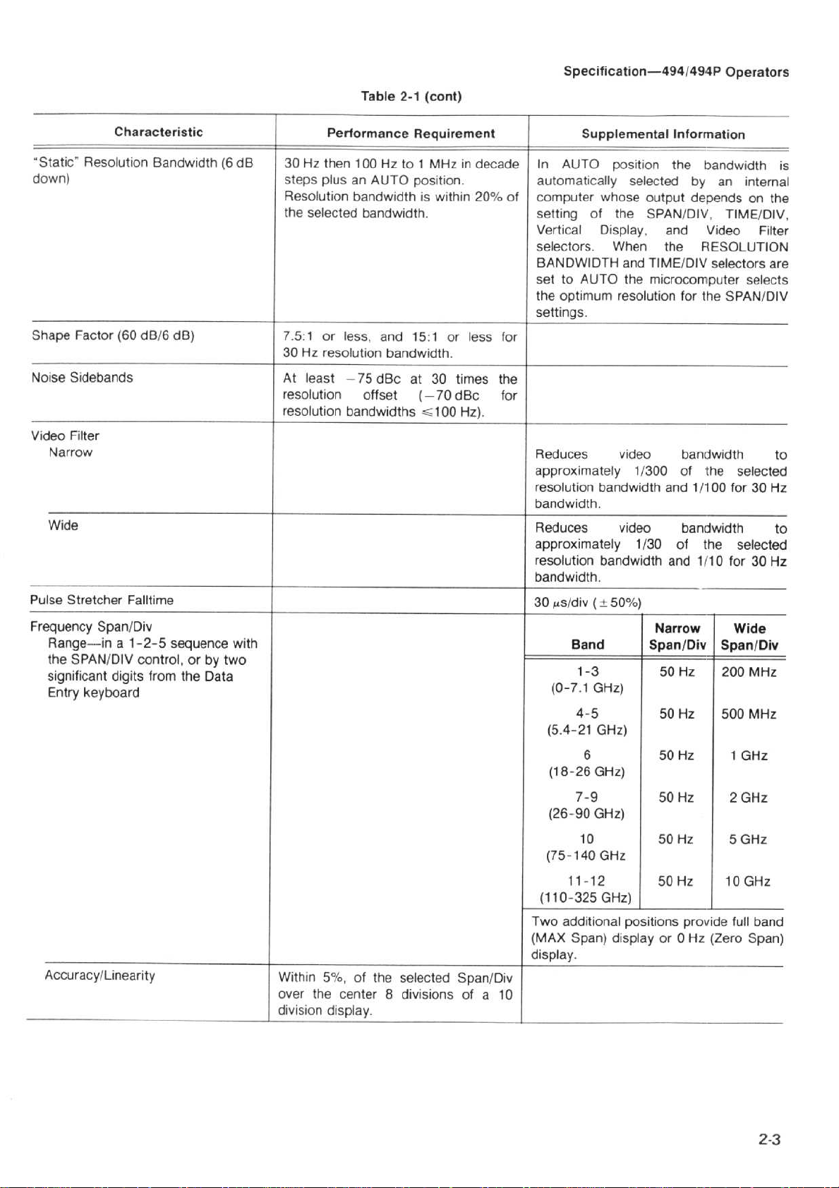
"Static"
down)
Shape
Noise
Video
Pulse
Frequency
Factor
Sidebands
Filter
N
arrow
Wide
Stretcher
Range-in
the
SPAN/DIV
significant
Entry
Characteristic
Resolution
(60
Falltime
Span/Div
a
1-2-5
digits
keyboard
Bandwidth(6dB
dBl6
dB)
sequence
control,orby
from
the
Data
two
with
Performance
30 Hz
then
100
steps
plusanAUTO
Resolution
the
selected
7.5:1
30 Hz
At
least-75
resolutionoffset(-70
resolution
bandwidthiswithin
bandwidth
or
less,
resolution
bandwidths
Hz
to
and
bandwidth
dBc
Requirement
MHz
1
position
.
15:1or less
at
30 times the
_100
in
decade
.
20%
.
dBcfor
Hz)
.
In
automatically
of
computer
setting
Vertical
selectors.When
BANDWIDTH
settoAUTO
the
settings
for
Reduces
approximately
resolution
bandwidth
Reduces
approximately
resolution
bandwidth
30
,s/div(±50%)
(0-7.1GHz)
(5
Suppleme
AUTO
of
optimum
.
Band
1-3
4-5
.4-21
position
selected
whose
the
Display,
and
the
resolution
video
1/300
bandwidth
.
video
1/30
bandwidth
.
GHz)
ntal
Information
the
bandwidth
by an
output
SPAN/DIV,
depends
and
Video
the
RESOLUTION
TIME/DIV
microcomputer
and
and
Narrow
Span/Div
50
50
selectors
for
the
bandwidth
of
the
11100
bandwidth
of
the
11'10
Hz
Hz
internal
on
TIME/DiV,
Filter
selects
SPAN/DIV
selected
for30Hz
selected
for30Hz
Wide
Span/Div
200
MHz
500
MHz
is
the
are
to
to
Accuracy/Linearity
Within
over the
division
5%,
of
the
selected
center8divisionsofa
display
.
Span/Div
10
(18-26
(26-90
(75-140
(110-325
Two
additional
(MAX
display
6
7-9
10
11-12
Span)
.
GHz)
GHz)
GHz
GHz)
50
50Hz 2
50
50
po
sitions
displ
ayor0Hz(Zero
Hz
Hz
Hz
provide
1
5
10
full
GHz
GHz
GHz
GHz
band
Span)
Page 17
Specification-49414941'
Operators
Table
2-1
(cont)
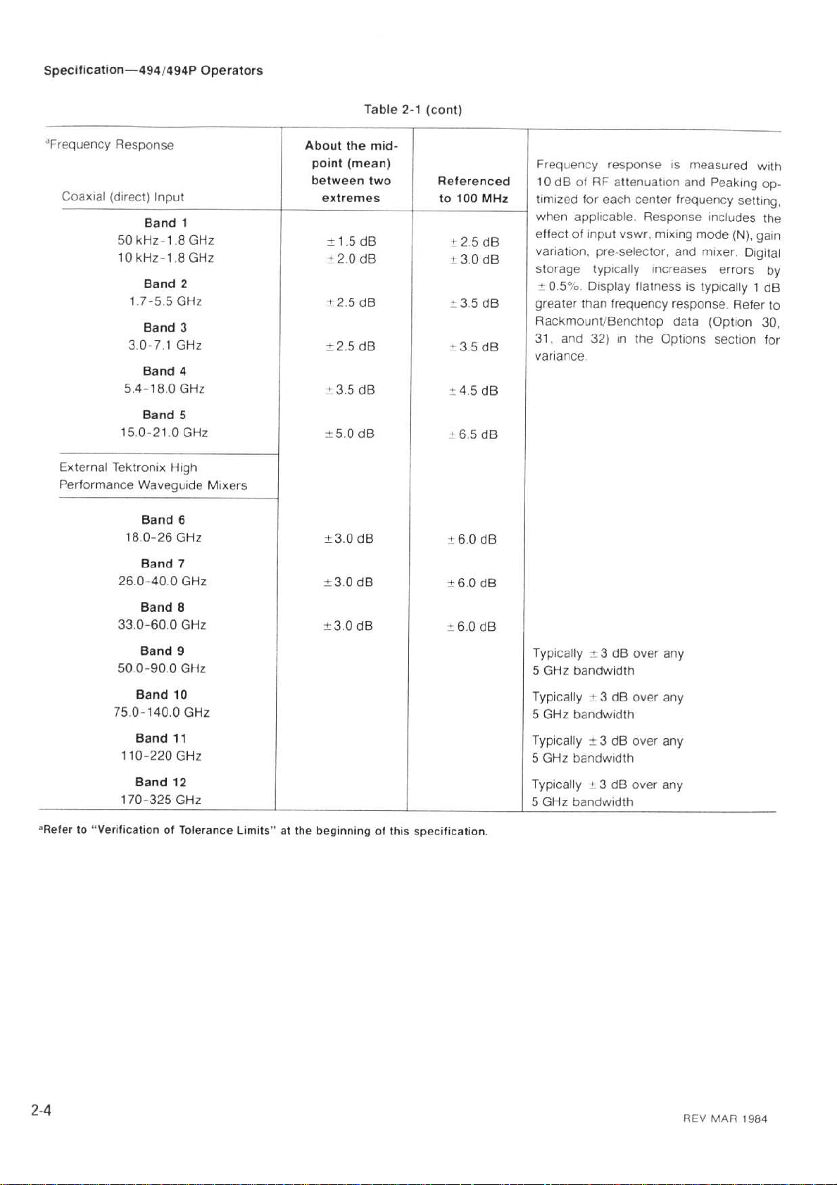
"Frequency
Coaxial
External
Performance
Response
(direct)
Input
Band
50
kHz-1.8GHz
10
kHz-1.8GHz
Band
1
.7-5.5GHz
Band
3
.0-7.1GHz
Band
5.4-18.0GHz
Band
15
.0-21.0GHz
Tektronix
Waveguide
Band
15
0-26
Band
26
.0-40.0GHz
1
2
3
4
5
High
6
GHz
7
Mixers
About
point
between
extremes
±1
±2.0
i 2.5dB
+2.5
-3.5dB
±5.0dB
±3.0dB
±3.0dB
the
mid-
(mean)
two
.5cIB
dB
dB
Referenced
to
100
MHz
+2.5dB
+3.0
dB
+3.5dB
".3.5dB
.
4
.5
dB
+ 6.5d
6.0d
B
-4-60
dB
Frequency
10dBofRFattenuation
timized
when
effectofinput
variation,
storage
4 0
.5p
greater
Rackmount/Benchtop
31.and
variance
for
response
each
center
is
frequency
applicable.Response
vswr,
mixing
pre-selector,
typically
,
o
.
Display
than
frequency
and
increases
flatnessistypically
response
data
32)inthe
Options
.
measured
and
Peaking
includes
mode
mixer
(Option
section
with
op-
setting,
the
(N),
gain
.
Digital
errors by
1
dB
.
Refer
to
30,
for
B
Band
8
33
.0-60.0GHz
Band
9
50.0-90.0GHz
Band
10
75
.0-140.0GHz
Band
11
110-220
170-325
"Referto"VerificationofTolerance
Band
GHz
12
GHz
Limits"atthe
t3.0dB
beginning
of this
"6.0
dB
specification
.
Typically-3dB
GHz
5
bandwidth
over
Typically±3dBover
5
GHz
bandwidth
Typically±3dB
5
GHz
bandwidth
Typicallyi3dB
5
GHz
bandwidth
over
over
any
any
any
any
2-4
REV
MAR
1984
Page 18
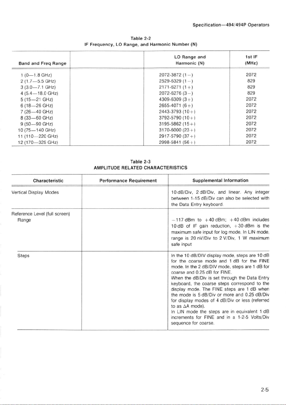
IF
Frequency,
LO
Table
Range,
2-2
and
Harmonic
Number
Specification-4941494P
(N)
Operators
Band
and
1
(0-1.8GHz)
2(1.7-5.5GHz)
3(3.0-7.1GHz)
4(5.4-18.0GHz)
5
(15-21
6
(18-26
7
(26-40
8
(33-60
9
(50-90
10
(75-140
(110--220
11
12
(170-325
Characteristic
Vertical
Display
Freq
GHz)
GHz)
GHz)
GHz)
GHz)
GHz)
Modes
GHz)
GHz)
Range
Table
AMPLITUDE
Performance Requirement
RELATED
2072-3872(1-) 2072
2529-6329(1--)
2171-6271(1+)
2072-6276
4309-6309
2655-4071
2443-3793
3792-5790
3195-5862
3170-6000
2917-5790
2998-5841
2-3
CHARACTERISTICS
10
between
the
Range
LO
Harmonic
(3-)
(3+)
(6+)
(10+)
(10
(15+)
(23+)
(37+)
(56-1
dBIDiv,
Data
and
(N)
+-)
)
Supplemental
2 dBIDiv,
1-15
dBIDiv
Entry
keyboard
1st
(MHz)
829
829
829
2072
2072
2072
2072
2072
2072
2072
2072
Information
and
linear.Any
can
alsobeselected with
.
IF
integer
Reference
Range
Steps
Level
(full
screen)
-117
dBm
10
dB
ofIFgain
maximum
rangeis20
safe
input
In
the 10
for
the
coarse
mode.In
coarse and
When
the dBIDivisset
keyboard,
display
the
for
toas4A
In
increments
sequence
mode
display
LIN
mode
mode.The
to
+40
dBm;+40
reduction,
safe
nVIDivto2
dBIDIV
the2dBIDIV
.25dBfor
0
the
isSdBIDivormore
modes
mode)
for
for
coarse
for
input
display
mode
coarse
FINE
of
.
the steps
FINE
.
log
mode,
and1dB
mode,
FINE
through
steps
4
dBIDivorless
areinequivalent1dB
andina
dBm
+30
.InLIN
mode
VIDiv,1W
steps are 10
steps
.
the
correspond
steps
are1dB
and0.25
1-2-5
dBm
for
are
Data
includes
is
the
mode,
maximum
the
FINE
1
dB
Entry
the
to
when
dBIDiv
(referred
VoltslDiv
dB
for
Page 19
Specification-4941494P
Operators
Table
2-3
(cont)
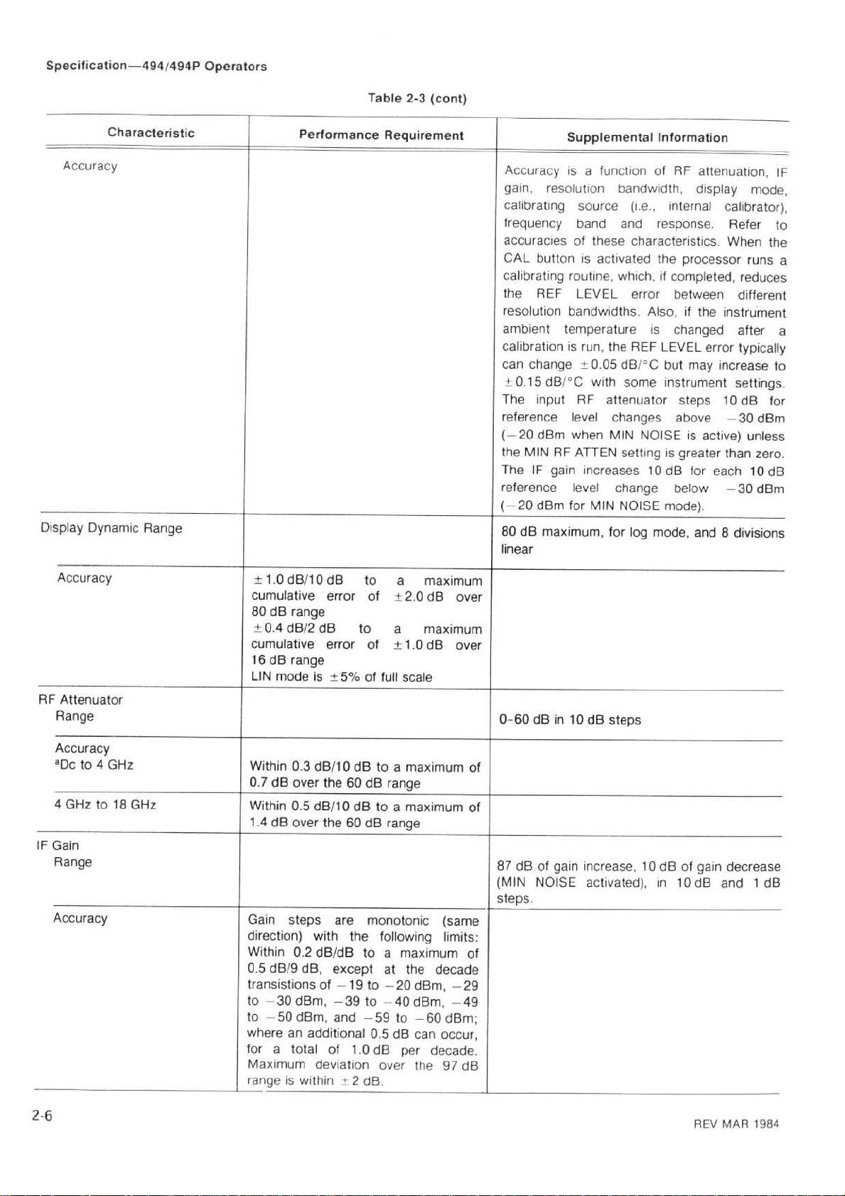
Accuracy
Display
Characteristic
Dynamic
Range
Performance
Requirement
Supplemental
Accuracy
gain,
calibrating
frequency
isafunction of
resolution
source(i.e.,internal
band
accuraciesofthese
CAL
buttonisactivated
calibrating
the
resolution
ambient
routine,
REF
bandwidths
temperature
LEVEL
calibrationisrun,
can change
+0
.15
The
input
reference
(-20
the
MIN
The
IF
reference
(
-20
80
dB
dBi'C
dBrn
RF
gain
dBm
for
maximum,
{:0
.05
with
RF
attenuator
level
when
ATTEN
increases
level
MIN
linear
Information
RF
attenuation,
bandwidth,
and
display
response.Refer
characteristics.When
the
processor
which,ifcompleted,
error
between
.
Also,ifthe
is
changed
the
REF
LEVEL
dB/'C
some
error
but
may
instrument
steps 10
changes above
MIN
NOISE
is
active)
settingisgreater
for
10
dB
change
NOISE
for
log
below
mode)
mode,
and8divisions
.
mode,
calibrator),
runs
reduces
different
instrument
after
typically
increase
settings
dB
-30
dBm
unless
than
zero
each
10
--30dBm
IF
to
the
a
a
to
.
for
.
dB
Accuracy
RF
Attenuator
Range
Accuracy
"Dcto4
4
GHzto18
IF
Gain
Range
Accuracy
GHz
GHz
±1
.0
dB/1
cumulative
80dBrange
±0.4
d812
cumulative
16dBrange
LIN
mode
Within
0
.3
0.7dB
over
Within0.5
1.4dB
over the60dB
Gain
steps are
direction)
Within0.2
0.5dB/9
clB,
transistions
to
-30
dBm,
to
-50
dBm,
where
an additional
for
a
total
Maximum
range
is
within±2dB
0
dB
to
error
of
dB
to
error
of±1.0dB
is
+5%
of
full
dB/10
dBtoa
the60dB
range
dB/10dBtoa
range
monotonic
with
the
following
dB/dB
of
toamaximum
except
-19
to
-39
to
and
-59
at
-20
-40
0.5dB
of1.0
deviation
dB
over
.
a
+2
.0
a
scale
maximum
maximum
the
dBm,
dBm,
to
-60
can
per
the
maximum
dB
over
maximum
over
(same
limits
decade
-29
-49
dBm
occur,
decade
97
dB
of
of
of
0-60
dBin10dBsteps
87
dB
(MIN
steps
of gain
NOISE
.
increase,10dBofgain
activated),in10
dB
decrease
1
and
dB
:
;
.
2-6
REV
MAR
1984
Page 20
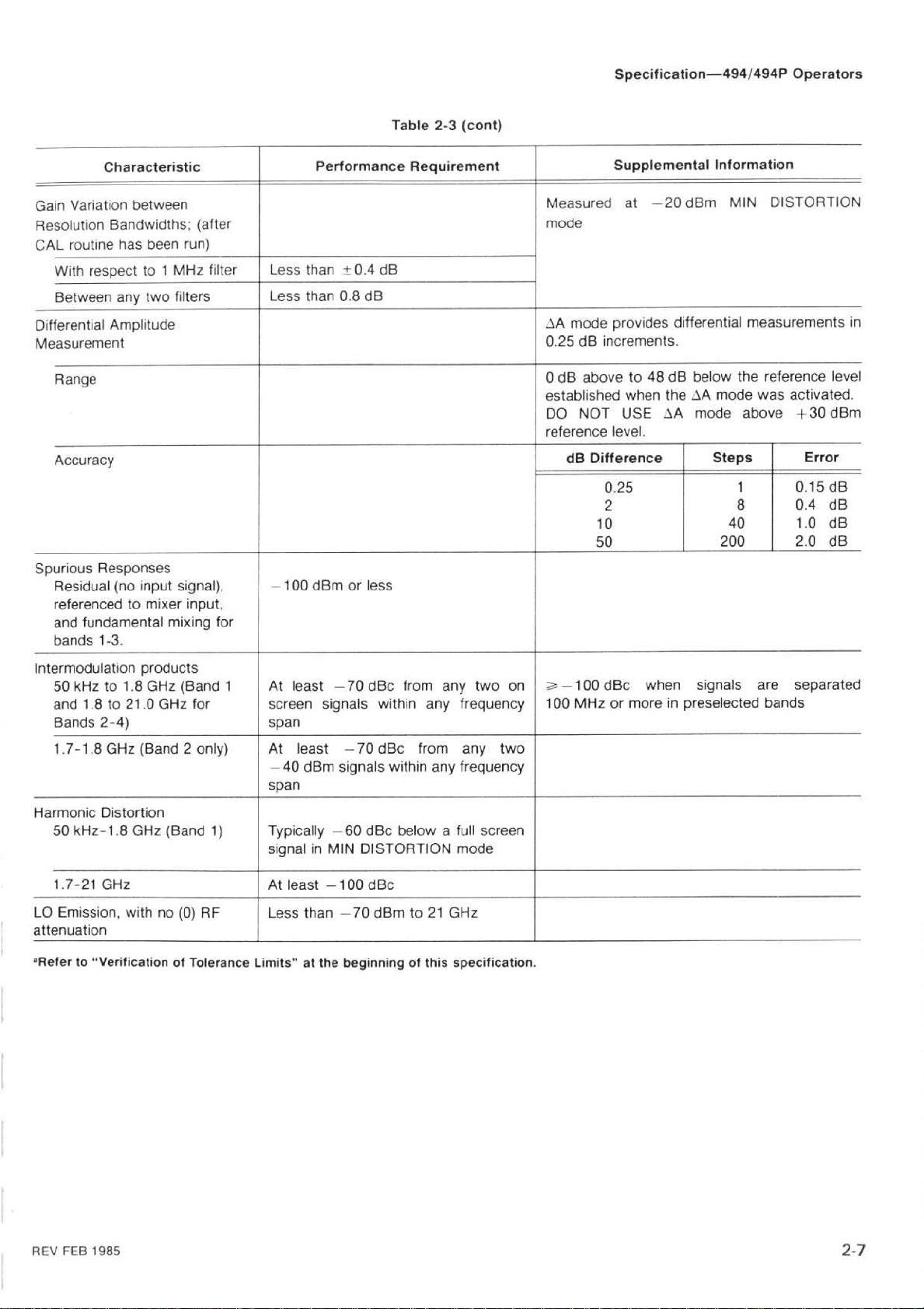
Table
2-3
(cont)
Specification-4941494P
Operators
Characteristic
Variation
Gain
Resolution
CAL
routine
With
Between anytwofi
Differential
Measurement
Range
Accuracy
Spurious
Residual
referencedtomixer
fundamental
and
bands
between
Bandwidths;(after
has
respectto1
Amplitude
Responses
(no
1-3
.
been
input
run)
MHz
lte
rs
signal),
input,
mixing
filter
for
Performance Requirement
than
Less
Less than0.8
-100
dBm
±0.4dB
dB
or
less
Measured
mode
-%A
mode
0
.25
0dBabove
established
DO
reference
increments
dB
NOT USE
dB
Difference
0
2
10 40
50
Supplemental
at
-20
provides
when
level
.25
differential
.
to48dB
theJAmode
AA
.
Information
dBm
below
mode
Steps
200
MIN
DISTORTION
measurements
the
reference
was
activated
above
1
8 0.4dB
+30
Erro
0
.15
1.0d8
2
.0
in
level
.
dBm
r
dB
dB
Intermodulation
50
kHzto1.8GHz
and1.8
Bands
1
.7-1.8GHz
Harmonic
50
kHz-1.8GHz
1
.7-21
LO
Emission,
attenuation
oReferto"VerificationofTolerance
products
to 21.0GHz
2-4)
(Band2only)
Distortion
GHz
withno(0)
(Band
(Band
1
for
1)
RF
At
least
screen
span
At
-40
span
Typically
signalinMIN
At
Less
Limits"atthe
signals
least
dBm
least
-100
than --70
-70
dBc
-70
signals
-60
dBc
DISTORTION
dBc
beginning
within
dBc
within
dBm
from
from
below
to 21
of this
any
two
any
frequency
any two
any
frequency
full
a
mode
GHz
specification
on
screen
.
=-100
100
MHz
dBc
or
more
when
in
signals
preselected
are
bands
separated
REV
FEB
1985
2-
7
Page 21
75
Specification-494/494P
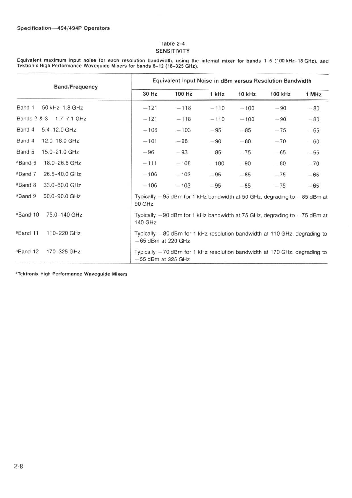
Equivalent
Tektronix
maximum
High
Performance
Band/Frequency
Band
150
kHz-1.8GHz
Bands2&
Band
Band
Band
aBand
aBand
aBand
aBand
31
.7-7,1
4
.4-12
5
.0
GHz
412.0-18.0GHz
515
.0-21.0GHz
618
.0--26.5GHz
7
26
.5-40
.0
833
.0-60.0GHz
950
.0-90.0GHz
input
GHz
GHz
Operators
noise
for
Waveguide
each
Mixers
resolution
for
bands
30
-96
-
-106 -103
---
Typically
90
GHz
Table
SENSITIVITY
bandwidth, using
6-12
118-325
Equivalent Input
Hz
100
-121
--121
-
106
-101
.111
106
-95
-103
dBm
2-4
the
-118
-118
-103
GHz)
Hz
internal
.
Noise
mixer
for
bands
in
dBm
versus
1
kHz
-110
10
-100
kHz
-110 -100
--95
-85
1-5
(100
Resolution
100
-90 -80
-90 -80
--75
-98 -90 -80 -70
-93
-108
forikHz
-85
-95
--
100
95
--75
-90
--85
-85
bandwidthat50 GHz,
- 65
-75
degradingto-85 dBm
kHz-18
Bandwidth
kHz
80
GHz),
1
MHz
-65
-60
-55
-70
-65
-65
and
at
aBand
1075
8and
11110-220
0
12170--325
-'Band
nTektronix
.0-140
High
Performance
GHz
GHz
GHz
Waveguide
Mixers
Typically
140
GHz
Typically
-65
dBm
Typically
dBm
--55
-90
-80
at
--70
at
dBm
dBrn
220
dBm
325
for1kHz
for1kHz
GHz
for1kHz
GHz
bandwidthat75 GHz,
resolution
resolution
bandwidthat110
bandwidthat170
degradingto-75 dBm
GHz,
degrading
GHz,
degrading
at
to
to
Page 22

RF INPUT
Input
Impedance
Maximum
1dBCompression
(minimum)
1
.7-2.0GHz
Otherwise
Optimum
linear
operation
External
Mixer
EXTERNAL
Fr
eque
ncy
Power
Waveshape
Input
Impe
Characteristic
Input
Safe
Point
level
for
REFERENCE
dance
Table
INPUT
SIGNAL
Performance Requirement
-28
dBm
--18
dBm
--25
dBm
1,2,5,
-15
or 10
dBm
CHARACTERISTICS
at
Min
Noise
at
Min
Distortion
MHz,
to
+15
dBm
2-5
+5
ppm
.
Specification-4941494P
Supplemental
N
Type
21GHz
50tt;
50
2
6
18-21
+30
pulse
duty
DO
INPUT
No RF
No RF
No RF
-30
achievedinMIN
not
Input
for
.0to-2
+1
Sinewave,
symmetryis40-60%)
50S2ac,
female
.
vswr
withRFattenuation
kHz-2.5GHz;1.3:1
GHz
.5-6
.0-18
dBm
width1us
factor of0.001
NOT
attenuation
attenuation
attenuation
dBm,
exceeding
foranIF
external
; 1.7:1
.0
GHz;2.3:1
GHz;3.5:1
(1
W)
APPLY
500Qdo
DC
referenced
DISTORTION
full
screen
signal
waveguide
.0V,70Ltsource
ECLorTTL.(Allowable
Information
connector,
(typically
(typically1.5
(typically1.9
(typically
continuous,
or less
withamaximum
(attenuator
VOLTAGE:TO
input
to
display
and
the
mixers.Bias
Operators
specified
710
db
-
1
.2
:1)
:1)
:1)
2.7:1)
75
W
peak,
limit)
.
THE
mixer.This
mode
when
.
sourceofbias
range
.
duty
cycle
to
RF
is
HORIZITRIG
Input
Voltage
Sweep
Trigger
MARKER/VIDEO
ACCESSORY
Pin
1-External
Pin
2-External
Pin
3-External
Pin
5-Chassis
REV NOV
1986
Range
(J104)
Gnd
Video
Sel
e
Preselector
Preselector
ct
Out
Return
1.0V
1
MHz
peak,
frequency15Hz
Dc
coupled
coupled
0to+
deflection
to
Maximum
Maximum
derate
above.Pulse
Video,0to+4V,ifExt
it
Adapter
marker
TTL
+15V
for
V
10
ac
linearlyto3.5Vrms
interfaces
to
internal
on
logic0selects
maximum
input
for
horizontal
trigger s
(dc+peak
input:50V(dc
insertanexternally
ignal
ac)
input
:30Vrms
widthis 0.1usmini
with
the
video.Marker0to--10
the
to
at
Videoisselected;or,
1405
External
drive
for
-+
100
TV
full
10
mum
Video
and
screen
peak
ac)
kHz
then
kHz and
.
Sideband
generated
Input
2-
ac
.
V
9
Page 23
Specification-4941494P
Operators
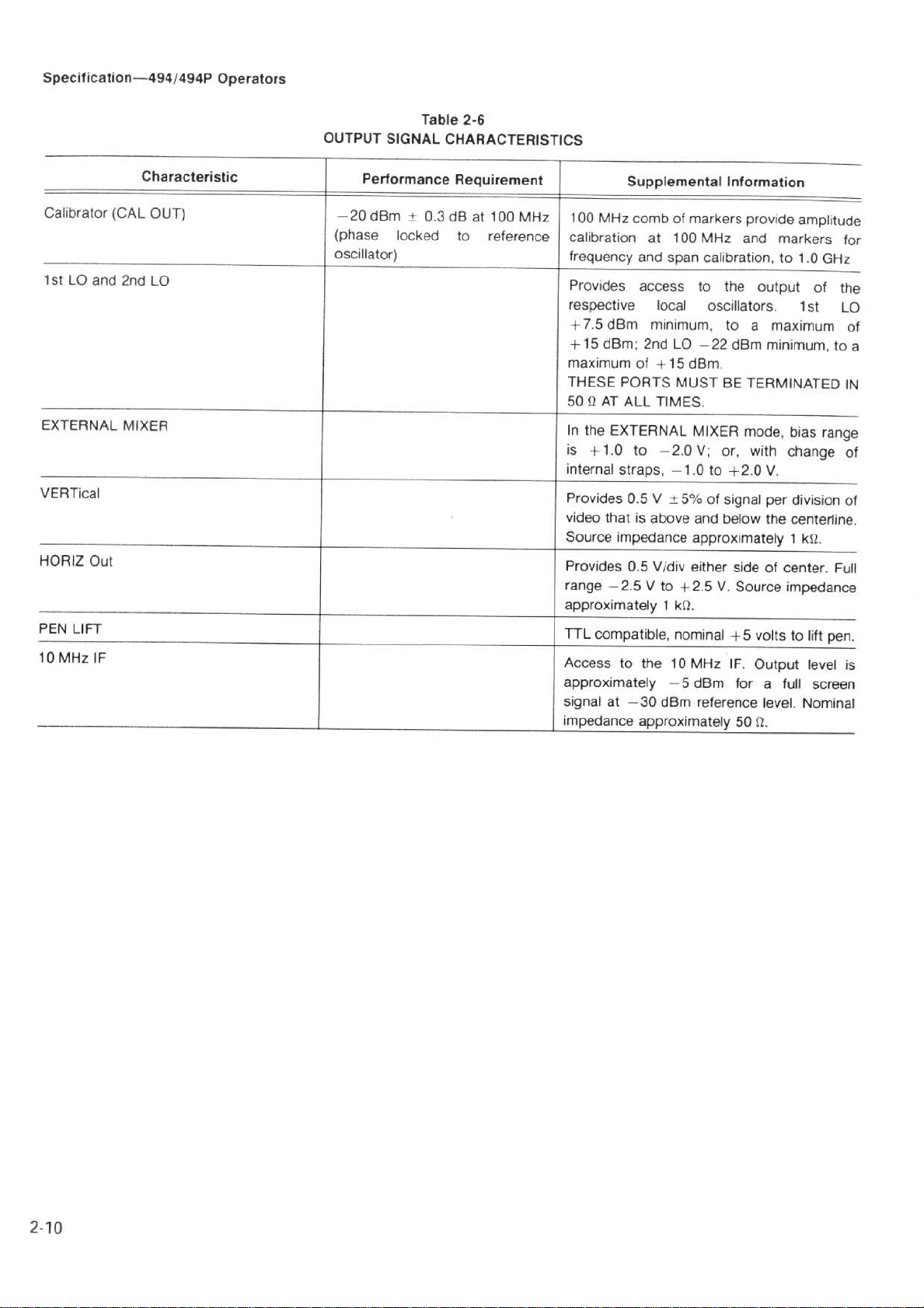
OUTPUT
SIGNAL
Table
2-6
CHARACTERISTICS
Calibrator
1stLO
EXTERNAL
VERTical
HORIZ
PEN
10
Out
LIFT
MHz
and
IF
Characteristic
(CAL
OUT)
2nd
LO
MIXER
_-
_
.
Performance Requirement
-20
dBm
t
0
.3
dBat100
(phase
oscillator)
locked
to
MHz
reference
Supplemental
100
MHz
combofmarkers
calibrationat100
frequency
Provides
respective
+7.5dBm
+15
maximum
THESE
50QAT
In
the
is
+1
internal
Provides 0.5V
video
Source
Provides0.5
range
approximately1k12
TTL
Access
approximately
signal at
impedance
and
span
access
local
minimum,
dBm;2nd
PORTS
ALL
EXTERNAL
.0
straps,-1.0to+2.0V
that
impedance
--2.5V
compatible,
to
LO
of+15
MUST
TIMES
to
-2
±5%
is
above
Vldiv
to
+2.5V.Source
nominal
the 10
-5
-30
dBm
approximately
Information
provide
MHz
and
markers
calibration,to1
to
the
output
oscillators
to
-22
dBm
.
BE
.
MIXER
.0V;or,
of
signal
and
below
approximately1kQ
either
.
MHzIF.
dBm
reference
.
a
maximum
dBm
minimum,
TERMINATED
mode,
with
.
per
the
side
of
voltstolift
+5
Output
forafull
level.Nominal
500.
amplitude
for
.0
GHz
of
the
1st
LO
of
to
IN
bias
range
change
division
centerline
center.Full
impedance
.
pen
level
screen
of
of
is
a
.
.
Page 24
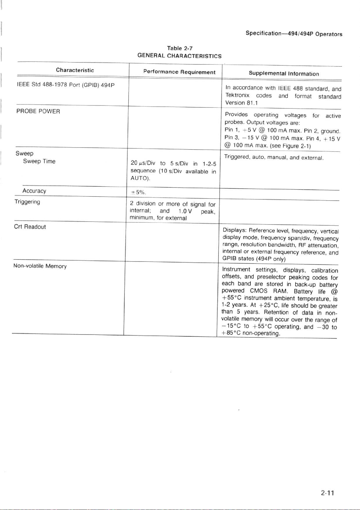
GENERAL_
Table
2-7
CHARACTERISTICS
Specification-494/494P
Operators
IEEE
Std
PROBE
Sweep
Triggering
Crt
Non-volatile
POWER
Sweep
Accuracy
Readout
Characteristic
488-1978
Time
Memory
Port
(GPIB)
494P
Performance
20
us/Div
sequence
AUTO)
-+
.
5%
.
2
division
internal
minimum,
to5s/Div
(10
.
or
;
and
for
Requirement
in
s/Div available
more
of signal
1.0V
external
1-2-5
for
peak,
In
accordance
Tektronix
Version81.1
Provides operating
probes.Output
Pin
1,
+5
Pin3,-15
100
mA
Triggered,
in
Displays
display
range,
internal
GPIB
Instrument
offsets,
each band
powered
+55°C
1-2
than
volatile
-15°C
+85°C
:
mode,
resolution
or
states(494P
and
instrument
years
5
years
memory
to
non-operating
Supplemental
with
codes
voltages
V
100
@
V
100
@
max
.
(see
auto,
manual,
Reference
frequency
bandwidth,
external
settings,
preselector
are
stored
CMOS
.
At
+25°C,
.
Retention
will
+55°C
Information
IEEE
488
and
voltages
are
mA
max.Pin
mA
max.Pin
Figure
and
level,
frequency,
spanldiv,
frequency
onl
y)
displays,
peaking
in
RAM
.
Battery
ambient
life
should
of
occur
over
operating,
.
standard,
format
:
RIF attenuation,
back-up
temperature,
standard
for
2,
ground
4,
2
'-1)
external
reference,
data
vertical
frequency
calibration
codes
battery
life
be
greater
in
the
range
and
-30
.
active
+15V
non-
and
.
and
for
is
of
to
Page 25

Specification-4941494P
Operators
PowER.The
PROBE
panelofthis
probe
systems.Itisnot
used
as a
power
probes
or
with
this
use
instrument
other
source
PROBE
sourcetor
accessories
.
POWER
provides
recommended
applications
which
connector
operating
that
other
are
specifically
power
these
than
on
the
for active
connectors
the
compatible
designed
rear
be
for
2726-21
inputVoltage
Power
Power
Leakage
powertothis
If
turn
the
Figure
Characteristic
Current
instrumentisinterrupted,itmaybenecessary
POWER
switch
for5seconds
OFF
then
ENVIRONMENTAL
2-1.Probe
POWER
backON.
power
Table
2-8
REQUIREMENTS
to132
90
115
At
5
mA
NOTE
re-initialize
to
Table
2-9
CHARACTERISTICS
connector
.
Vacor180to250
V,60Hz;210
maximum
the
Description
Vac,48to440
watts
maximum,3.2
microcomputer
;
Hz
amperes
when
powerisrestored,
.
.
MIL
Meets
Temperature
Operating
Non-operating
T-28800C,
and
Humidity
type
111
class3,style
Characteristic
specifications,
C
comprisedofthe following
Description
-10to+55°C195%
mentistested
-62
to
+85°C
and
.
(+5%,
meets
:
-15
-0%)
to
-*-55°C)
relative
humidity
(Instru-
.
Page 26
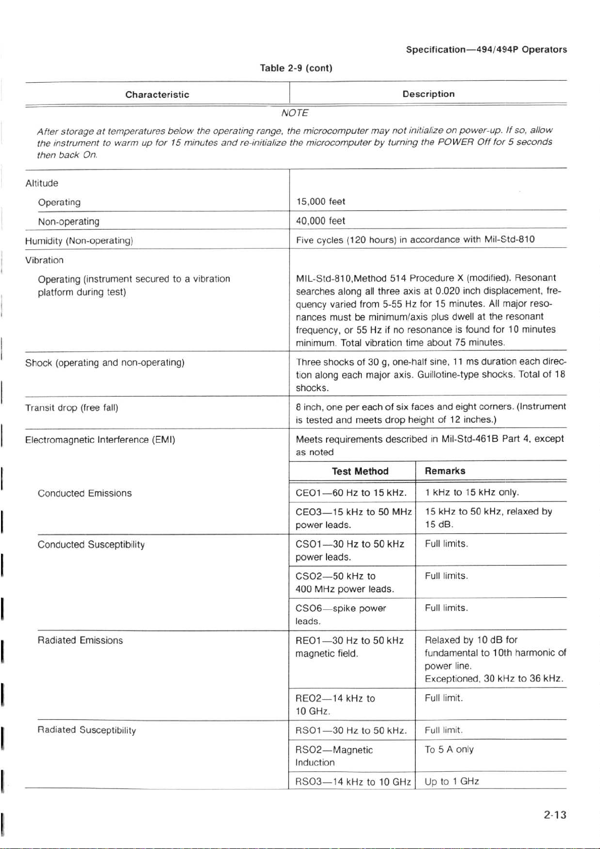
After
storage
instrumenttowarm
the
then
backOn.
Altitude
Operating
Non-operating
Hu
Vibration
(Non-operating)
midity
Operating
platform
at
temperatures
(instrument
during
test)
Characteristic
below
for15minutes
up
securedtoa
the
operating
and
vibration
Table
2-9
I
NOTE
range,
the
re-initialize
the
(cont)
microcomputer
microcomputer
15,000
40,000
Five
MIL-Std-810,Method
searches
quency
nances
frequency,or55
minimum.Total
feet
feet
cycles
varied
must
(120
along
all
from
be
minimum/axis
vibration
Specification-4941494P
Description
may
by
hours)inaccordance
three
Hzifno
initialize
not
turning
514
ProcedureX(modified).Resonant
axisat0.020
5-55
Hz
resonanceisfound
time
on power-up.!f
the
POWER
for15minutes.All
plus
about75minutes
Off
for5seconds
with
Mil-Std-810
inch
displacement,
dwellatthe
for10minutes
Operators
so,
major
resonant
.
allow
fre-
reso-
Shock
(operating
Transit
Electromagnetic
drop
Conducted
Conducted
Radiated
(free
Emissions
and
non-operating)
fall)
Interference
Emissions
Susceptibility
(EMI)
Three
shocks
tion
along
shocks
8
is
Meets
as
CE01-60
CE03-15
power
CS01-30
power
CS02--50
400
CS06-spike
leads
RE01-30
magnetic
.
inch,
one
tested
requirements
noted
leads
leads
MHz
.
Test
of30g,
each
per
and
meets
Method
Hzto15
kHzto50
.
Hzto50
.
kHz
power
Hzto50
field
.
one-half
major
axis
eachofsix
drop
describedinMil-Std-461BPart4,except
kHz
MHz
kHz
to
leads
.
power
kHz
sine,11ms
Guillotine-type
.
faces
and
height
of 12
Remarks
1
kHzto15
.
kHzto50
15
15dB.
limits
Full
Full limits
Full limits
Relaxed
fundamental
power
Exceptioned, 30
duration
shocks.Totalof18
eight
corners.(Instrument
inches
.)
kHz
only
kHz, relaxed by
.
.
.
by 10
dB
10th
to
line
.
kHzto36
each
.
for
harmonic
direc-
of
kHz
.
Radiated
Susceptibility
RE02-14
10
GHz
RS01-30
RS02-Magnetic
Induction
RS03-14
kHz
.
Hzto50
kHz
to
kHz
to10GHz
.
Full
limit
Full
limit
A
To 5
Upto1
.
.
only
GHz
2-13
Page 27

Specification-4941494P
Operators
PHYSICAL
Table
2-1D
CHARACTERISTICS
Weight
(standard
manuals)
Dimensions
Withoutfrontcover,
With
front
cover,
Characteristic
accessories
handle,or f
feet,
and
and
cover,
except
eet
handle 9
52 pounds
6
.9X12.87X19
.15
folded
fully
(24 kg)
X
15
.05X23.1inches
back over
extended
maximum
.65
inches
the
instrument,
Description
(175
X
327X499
(232 X
382X587
28
.85
inches
millime
ter
millimeters)
(732.8mm)
s)
with
with
the
the
handle
handled
c
33
.02
38.1cm(15in.)
cm
113.0in)
-4
--r-{
Figure
2-2.Dimensions
57.6cm
.
(23in.)
2726
10B
Page 28

494/494P
SAFETY
STANDARD
AND
Table
2-11
REGULATORY
REQUIREMENT
Specification-494/494P
CONFORMANCE
Operators
Safety
Regulatory
CSA
FM
ANSI
VDE
Standards
IEC
0871
C39
.5
(2nd
348
Requirement
Class
Subject
edition)
B
Electrical
Electrical
Safety
and
Safety
Regulations
and
Bulletin
Utilization
Requirements
Controlling
Requirements
Installations
Standard
for
Instrumentation
for
for
RFI
Suppression
Description
Class
3820
Electrical
ElectronicMeasuring
and
of High
Electronic
Apparatus
Frequency
Measuring
;
Apparatus
Page 29

Page 30

Section
3-494I494P
Operators
INSTALLATION
Introduction
This
section
quirements, repackaging,
494/494P
Unpacking
Before
tainer
or
carton
contains
Refertothe
Operators
Replacement
thereismechanical
does
local
container
Inc
electrically
damage
Procedurestocheck
areinthe
check
erly.This
receivingorincoming
formance
providesacheckofall
as
is
If
the contentsofthe
not
Tektronix
.
The
instrument
procedure
listedinthe
describes
Spectrum
and
Initial
unpacking
carton,
the basic
meet
and
inspect
damaged,
instrument
Standard
manualorthe
listinginVolume
operational
Field
is
damaged,
before
check
verification
shipment.It
meet
Operation
verifies
should
Specification
Analyzer
the
notify
damage
Office or
notify
was
or
functional
inspections.A
procedure,inthe
specified
unpacking,
and
.
Inspection
494I494P
for
signsofexternal
the
and
Accessories
list
following
2 of
shipping container
or
check
representative.If
the
inspected
should be
exceed
section.Performing
the instrumentisoperating
satisfy
section
installation,
storage
carrier.The
defect,orif
requirements,
carrier
all
or
the
performance
information
from
its
its
standard accessories
listinSection1of
the
Mechanical
the
Service
are
as
wellasTektronix,
both
mechanically
freeofmechanical
electrical
operational
requirements
detailed
Service
.
shipping
damage.If
shipping
incomplete,
the
specifications
performance
the
electrical
requirements,
AND
FOR
power
re-
for
the
con-
the
carton
the
Parts
Instructions
if
instrument
contact your
the
shipping
and
functional
prop-
for
most
per-
instructions,
USE
ing
or
first
pullingupandinon
on the
unlatched
lifting
The
anglestoserve as a
top
rearofthe
panel,
dle,
.
.
.
pressinat
desired
Removing
can
moved
Installation
sionsofthe
tion
manual.Refer
If
the
and
panels
unlessitis
damaging
mounted
PREPARATION
transporting
cover.The
and
the
cover
handle of the
so instruments
position
be
hazardous.The
by
rackmount
tippedupto
of the
the
instrument.The
the
doortothe
opened
.
both
or
qualified
instructions
instrument
held.Use
the
above
by
pressing the
494I494P
tilt
stand,
instrument
canbestacked.To
pivot
points
.
replacing
installationtoqualified
cabinet,
front
the
the
service
for
are
described
versionisextended
gain
access
it
care
panelorequipment
494/494P
two
release
accessories
can
oritcanbepositionedatthe
between
and
cabinetonthe
cabinet
personnel
rack
the
to
can
fall
when
.
coverisremoved
latches,
latchtothe
positionedatseveral
be
the
rotate the
should
.
mount/benchtop
in
the Service
the
bottom
back
doing
then
compartment
side
feet
and
the
position
service
outofthe rack
into
thistoa
handle
instrument
only
be
personnel
or
the rack
may
that
the
back
by
pull
up
is
and
rear
han-
to the
re-
ver-
Instruc-
void
be
.
The
494I494P
air
flowinthe
Feet
on
instrument
air
in
through the
locating
might
venient
mixers
the instrument
block
The
front
placetostore
.
Use
the
canbeinstalledinany
four
is
stacked
the
panel
the
bottom
air
corners
bottom
intake
cover
cover
and
with
where
accessories
to
position that
out the
allow
other
and
.
providesadust-tight
protect
rear of
ample
instruments.A
paper,
the
air
plastic,
and
front
expels
the instrument
clearance
out
the
external
panel
evenifthe
fan
back.Avoid
like
or
seal
and
waveguide
when
allows
draws
material
con-
stor-
Power
.
power
tors
power
isolatedorabove
on
volt
since
tion
frontofthis
Source
The
494I494Pisdesigned
source
(neutral)atground
sources
a multi-phase
single-please,
only
within
and
that
where
the
line
the
unit.Refertothe
manual
Power
oneofits
has
both
ground
system
three-wire
conductor
.
Requirements
to
operate
(earth) potential
current-carrying
potential
or
across
system)
has
from
current-carrying
(such as
the
legsofa
is
not
over-current
Safety
a single-phase
conduc-
.
Operating
conductors
phase-to-phase
110-220
recommended,
(fuse)
protec-
Summary
at
from
are
the
Page 31

Installation
The
with
the
ment
is
connectedtoany
connectedtoan
be
The
230
Vac
180to250
ments
power
service
range are containedinthe
Power
in
Figure 3-1
Repackaging
When
vice
Center
and
Preparation
ac
power
connectorisa
ground
frametoprovide
494/494P
nominal
are
input
personnel.Instructions
(earth)
lead
electrical
other
earth
canbeoperated
line
voltage
.
Refer
Shipment
440
back-panel
Vac,
at48to
printedona
jack
cord
configurations
for
the
494/494Pistobeshippedtoa
for
serviceorrepair,
for
Use-494/494P
three-wire
connected
power
ground
witharangeof90to132
Hz.Power
power
Service
for
directlytothe
shock
protection.If
source,
.
from
plate
input
changes
for
changing
Instruction
the
instrument
attachatag
the
unit
either
and
voltage
mounted
Operators
polarized
the
frame
115
Vac
require-
below
to
qualified
input
voltage
manual,
are
shown
Tektronix
showing
plug
instru-
unit
must
or
or
the
Ser-
:
owner
and
address,
be
contacted,
the
service
not
available,
1.Obtain
dimensions
ment
dimensions,toallow
instrument
2
.
Install
with
polyethylene
3.Cushion
terial
or
the
instrument
4.Seal with shipping
complete
required.If
repackage
a
that
weights
the
urethane
.
carton
areatleast
the
name
of
individualatyour
serial
number,
the
original
the
corrugated
of
and
the
front
cover
sheetingtoprotect
equipment
between
foam
tapeorindustrial
packageisunfit
equipment
six
inches
for
cushioning.Table
carton
and
on
all
the
andadescription
as
follows
cardboard
more
than the
strength
surround the
sides
carton
the
finish
requirements
with
and
stapler
firm that
for
:
having
3-1
instrument
.
packing
the
sides
.
can
use
or
inside
equip-
lists
.
ma-
of
of
Power
Cord
North
American
120V/1
Australian
240V/1
Option
5A
A3
OA
Number
Figure
.
International
3-1
Universal
North
power
220V/1
American
240V/1
cord
configuration
A1
Euro
3A
A4
5A
(Option
A1-A5)
for
4941494P
240V/1
250V/6A
.
A2
UK
3A
A5
Swiss
as18-17
3-2
Page 32

and
SHIPPING
Gros
s
Weight
Table
CARTON
3-1
TEST
STRENGTH
Carton
Test
Strength
Installation
environment
in
an
mental
specifications
Preparation
that
.
meets
for
Use-4941494P
the non-operating
Operators
environ-
Pounds
0-10
10-30
30-120
120-140
140-160
Storage
Short
storage
Term-There
(less
than
Kilograms
0-3.73
3
.73-11
.19
11
.19-44
.76
44
.76-52
.22
52
.22-59
.68
arenorequirements
90
days)
other than store the instrument
Pounds
200
275
375 140
500 186
600
for
Kilograms
74
.6
102
.5
.0
.5
223
.8
short
term
Term-I
Long
days,
require
with
have
retain
batteryinthe instrument
dessicant
any
than
90
instrument.The
not
does
por
bag
the
environmental
If
you
Field
Officeorrepresentative
¬
plantostore
you
the
shipping
removal.Package
and
storeina
non-operating
questions,
contact
.
the
instrument
containertorepackage
is
the
instrumentina
location that
specifications
your
Iethium,
.
local
Tektronix
for
more
the
which
va-
meets
Page 33

Page 34

Section
4-494P
Operators
CONTROLS,
Introduction
This
section
tors,
indicators,
4-1
connectors.Thisisfollowed
checkoutofthe
the
whereinamessage
tion
lectorsorbuttonsonthe
wellasprimary
tered
modesorselect
are
Analyzers,
for
4-2
and
control
The
4941494P
of
any
nomenclature)
identicaltothe
analyzers
describes
and
show
instrument
functions
selected
function,
functional
thus
the
in
this
connectors
and
identify
.
featuresahelp
will
come
controlorpushbutton.Many
front
the
pushbuttons
controls
basic
family
the
functionofthe
for
these
(in
Section
and
some
mode
on
screen
panel
In
their
primary
parameters
on
the
operational
.
CONNECTORS,
INDICATORS
controls,
the
4941494P.Figures
controls,
performasecondary
set
.
492 and
procedureisthe
selectors,
5)byan
basic
applications
(press
HELP
describing
mode
either
Most
primary
496
operational
button)
the
of
the
(black
operational
modes
Spectrum
selec-
and
func-
se-
as
let-
same
of
When
the
shift
tionormode
In
addition,
selected
tion
.
The
tion
(black
nectors;then the
applicable.In
display
included
is
pressing
function
following
lettering)ofthese
some
mode
or
.
sequence
implemented
the
and
return
instructions
second,orshift
casesarun-down
parameter
is
<SHIFT>
the
first
from the
AND
completed
and
the
instrumenttonormal
describe
selectors,
function
shift
button
Data
the
mode
will
the
controls,
(blue
on
how
Entry
4418-30
entered
cancelled
cancel
primary
and
lettering)
to
enter
keyboard
func-
.
the
opera-
func-
con-
if
a
is
In
their
secondaryorshift
ture)
the
pushbuttons
ditional
Entry
add
the
(+dBm
dataisentered
Shift
two
blue
LEVEL,
are
These
the
board
corrected.In
through
data
keyboard
numerical
entry
with
or
-dBm),
Messages
Functions
Entering
buttons
used
keyboard.A
lettered
dBIDIV,
to
are
the
area,
each step
some
is
activate
to
the
parameter
(orange
valuestothe
a
multiplier
or
display
are displayed
through
of
the
parameters
in
sequence.When
pushbuttons,
or
COUNT
add
numerical data
orange
used
addition
"BACK
to
.
lettered
back
a
message
mode
alternate functions
.
Buttons
lettered
the
entered
(GHz,
factor
on
the
keyboard
nomenclature)
MHz,
Pushbuttons
requires
an entry
such
as
RESOLN;those
and
numbered
SPACE"
button,
space
on
(blue
lettered
parameterorterminate
kHz,
(dB)
.
crt
to
guide the user
.
pressing
FREQ,
to
the
so
entered data
screen
nomenclaor
within
are
Hz), unit
more
is
made
SPANIDIV,
buttons
parameter
buttons
outside
guides
add
the
used
value
via
which
light
within
the
can
the
ad-
Data
as
than
the
REF
key-
be
user
to
O
.
Some
of the
that
are not
operation,
the
functionisservice
agnostics,
manual.A
at
the
endofthis
Syntax
tionstohelp
diagrams
Instrument
POWER-This
power
current
register
that
also
1
the
supply onoroff.When
instrument
0 (see
this
set-up
switched
st
mixer
from
The
internal
instrument
front
panel
pushbuttons
nomenclated.These
are
described
their shift
listingofthese
explain
Power
RECALL
can
in
when powerisswitched
overload
reference
powerisoff-thereisno
with
the
related,
functionisdescribedinthe
un-nomenclated
section
.
are
included with
their
operation
Control
push-push
front
be
easily
type
panel
SETTINGS/STORE
recalled.FullRFattenuation
and
damage
oscillatorisnot
have
shift
functions,ifthey
pushbutton
such
as troubleshooting
some
.
switch,
powerisswitched
set-up
is
.
explanation.If
buttonsisgiven
of
turns the
storedinmemory
description)
off
to
powered
standby
functions
pertain
the
descrip-
off,
protect
up
mode
to
di-
service
main
the
so
is
the
when
.
REV
MAY
1984
Page 35

Controls,
Connectors,
and
Indicators--4941494P
Operators
r
1
NPA
Crt
Controls
INTENSITY-adjusts
readout
controlled
READOUT-When
(illuminated),
The
positiononthe
the
trace
prompt
functions
GRAT
(illuminated),
to
bright.Graticule
photographing
illuminated)
foralow
and
.
crt
parameter
brightness.This
messages
.
ILLUM-When
the
position
light
environment
7l
Lai
Figure
the
brightnessofthe
text.Beam
this
focus
button
readoutofcontrol
readoutislocated
crt
bezel
.
Brightnessisproportional
button
activated
graticule
this
lights
by
function
are switched
illuminationisusually
displays.The dim
provides
appropriate
.
Juixfa
-I
`
-pu
1a
4-1.Front
is
parameters
panel
crt
trace,
automatically
is
activated
is
adjacenttotheir
does
not
affect
many
front
panel
is
activated
from
used
when
(button
illumination
E1
selectors,
.
on
to
dim
not
Tektroni
J
controls,
Sweep
TRIGGERING-One
selected
activated
READY
operation
494P
and
or
Scan
connectors
.
of
by
pushbuttons
.ASINGLE
light
are
also included
.
FREE
RUN-When
sweep
source
cancelled,
This
activatedinthe
correction
enabling
with
frequency
is
free
running without
.
When
selected,
including
button
also
hasashift
<SHIFT>
for
the
local
the
operatortooperate
reduced
performance,
cannotbecalibrated
single
displayanappropriate
four
triggering
that
SWEEP
this
button
all
other
sweep
oscillator
message
illuminate
pushbutton
for
is
regard
trigger
mode
function
mode,
is
the
if
.
The
.
modes
single
activated,
to
modes
.
and
the
frequency
disabled,
instrument
the
oscillator
crt
readout
441M1
can
be
when
plus
sweep
the
trigger
are
when
thus
will
a
4-2
BASELINE
CLIP-When
(illuminated),
baselineofthe
observe
eliminate
displays
the
readoutatthe
the
.
this
about
one
graticule
displayisclipped
bottomofthe
bright
baseline
functionisactivated
division
or
subdued.Used
when
photographing
screen,
at
or
the
to
to
INT-When
triggered
display
that
more.Other
single
sweep mode
LINE-When
the
ac
power
sweep.All
selected,
this
button
by
any
signalatthe
has an amplitude
trigger
modes
.
this
buttonisactivated,
line
voltage
other
modes
including
single
is
activated,
are
is
are
cancelled
sweep
the
left
edge
of2.0
cancelled,
a
used
to
when
mode
.
REV
sweep
of
divisions
including
sample
trigger
LINE
MAH
1984
is
the
or
of
the
is
Page 36

Controls,
Connectors,
and
Indicators-4941494iP
Operators
SINGLE
single
aborted.When
is
sweep
Selecting
Triggering
be
corrected on a
Any
will
The
0
armed
the
EXT-When
triggeredbysignals
to
50Vpeak
the
rear-panel
When
cancelled,
SWEEP-When
sweep
armed
and
will
triggered,
trigger
be ignored
READY
and
sweep
this
(maximum)
HORIZ/TRIG
EXT
run
SINGLE
mode
signal
ready
ends
selected,
is
including
is
activated
pressed
the
oscillator
only
While
.
the frequenciesofthe
regular
received
.
indicator
foratrigger
.
buttonispushed,
between1.0Vpeak
that
(EXT
the
single
sweep
this
buttonisfirst
the
and
again the
frequencyiscorrected.The
afteritreceivesatrigger
SWEEP
lights
does
the
sweep
basistomaintain
duringacorrection
when
signal.It
are
other
mode
current
sweep
not
circuit
the
the
sweep
(minimum)
applied
IN)
connector
modes
.
sweep
trigger
change
waiting
is
oscillators
accuracy
sweep
remains
through
are
pressed,
circuit
signal
the
are
cycle,
circuit
lit
until
to
is
is
is
the
rear-panel
to
voltage
horizontal
.
.
.
a
(endofsweep
MNL
the
previously described,
control
rampof0to+10V
(X)
periodic
basis
(manual)-With
spectrum
.
HORIZ/TRIG
Oscillator
axis
.
and
when
condition)
or
display
will
corrections
the
.
the
controlinthe
can
be
with
(EXT
sweep
sweep
manually
the
#N)
connector
10
divisions
are
crosses.i-10
MNL
scanned,
MANUAL
441
B-32
done
on
position
as
SCAN
A
of
V
MANUAL
position,
asitis
periodic
TIMEIDIV-This
5
s/div
and
be
selected
AUTO
the
maintain
DIV,
and
EXT
position
SCAN-With
this
rotated
basistomaintain
to20Ks/div,
MNL
modes,
(automatic)-With
sweep
a
calibrated
RESOLUTION
Vertical
(external
the
control
.
Oscillator
control selects
as the
.
rate
is
selected by
Display
input)-With
sweep
the
TIME/DIV
will
manually
corrections
frequency
in
a
5-2-1
sequence.AUTO,
following
the
controlinthis
the
display
BANDWIDTH,
selections
circuitisdriven
for
.
the
4418-31
scan
the
are
accuracy
sweep
describes,
microcomputer
most
FREQ
VIDEO
selector
by a
signal
in
the
MNL
spectrum
done
.
rates from
EXT,
can
position,
SPAN/
FILTER,
in
applied
on
also
this
to
.i
(POSITION)-These
position
axes.To
center
MAX,
line.The
user
Display
CENTER FREQUENCY-Tunes
Tuningisdonein0.1division
of
tuning
band2(1
the
a
21
Tuning
spans(i.e.,equaltothe
selected)
FREQUENCY
buttons
quency
crt
changed,
frequenciesismade.If
center
returning
Frequency,
used
the
display
adjust,
screen,
and
the
CAL
through
Parameters
the
selected
range
.7-5.5GHz)
extreme
GHz)
readout.When
left
the
dot
range
.
shift
rangeofthe
an
frequency
toaprevious
the
so the
Center
along the
position
when
display
function
the
adjustment
FREQ
depends
the
edgeofthe
will
tune
in
narrow
RANGE
the
frequency
current
the
attempttopreserve
limitofthe
originalLOfrequencies are
Frequencyispreserved
screwdriver
horizontal
the
center
FREQ
baseline
SPAN/DIV
on
<SHIFT> CAL
of
increments, regardless
SPAN/DIV
on
the
band;for
frequency
graticule,orin
onlytothe
spans
frequency
(band)---These
range
bandisdispilayed
frequency
thisisnot
bandisselected
without
band,
adjustments
and
frequency
is
the
bottom
these
controls
the
center
In
MAX
.
example,
dot
will
not
bandti(15-
right
is
identicaltowide
range
of
up
or
down
range
the ist
possible,
and
the nearest
changing
vertical
dot
other than
graticule
guides the
.
frequency
SPAN,
two
tune
of
center
the
(band)
2nd
.
Center
always
.
the
to
band
push.
Fre-
by the
LO
When
at
.
in
.
is
4-
3
Page 37

Controls,
Connectors,
COUNTER/COUNT
pushbutton performs
COUNTER-When
nal
at
1
Hz
resolution
(shift)
above
60dBdown
`SHIFT?COUNT
used
the
orange
nate
kHz,
truncatedtothe
to
the
AF-When
measured
selected
0
.00.The
from
this
changed.The
accurateofthe
the
center
activated
COUNT
narrow
.
---
"CF-If
spans,isdesired,
frequency
signal
will
inactive),
counted
reduced
without
frequency.The
to
retuning
signal.The
frequency
resolution
.
FREQUENCY
control
selects
display.The
Range
dependsonthe
and
the
dot
marker
resolution
mode.The
the
is
selected
noise
at
signal
level
from the
to
select
the
nomenciated
with
one
of
the
or
Hz)
buttons
decade
selected
pressed,
(see
(illuminated)
readout
resolution
frequency
General
the
now
referenceasthe
resolution
current
center
frequency
close-in
dot
marker and
be
then
counted
the
once
center
FREQ
any
span
and
the
FREQUENCY
count
resolution
readout
accuracy
SPANIDIV-This
the
frequency
spanldiv
is
indicatedbythe
frequency
Indicators-494/494P
RESOLN-This
the
following
activated
position
any
Freq
in
and
REF
RESOLN
desired
frequency
.
Counter
thatisless
:
(illuminated),
is
counted
Span/Div
the
COUNT
must
be 20
above
LEVEL
(blue
counter
Data
Entry
suffixes
resolution
a
.
lettering)-is
resolution
than
.
4418-33
offset
can
Operating
frequency
shows
CENTER
o¬the
resolution
Information).When
readout
the
offset
FREQUENCY
readout
frequency
will
resolution,
when AF
analysisofa
tune the
press
(evenifthe
signal
this
COUNTER
button.The
frequencyistuned
the
SPANIDIV
signal
will
can
be
to
and
the
resulting
is
the
current
continuous
span/div
of
the
crt
band.Selection
Operators
two
function
the
with
up
.
The
actual
RESOLN
dB
or
more
level
that
keys.Termi-
(GHz,
MHz,
will
or
equal
be
easily
goes
or
deviation
be
the
less
was
signal,
under
the
to
the
now
be
centered
center
the
center
counter
detented
analyzer
readout
is in
sig-
via
be
to
is
or
in
is
to
is
a
1-2-5
domain
ing
the
data
via
will
try
to
selector
RESOLN
When
the
span
position,
beyond
baseline
indicates the
span.This
be
center
reduced
the
analyzer
displays
the
time
changes
RESOLUTION
detented
Bandwidth
range
is30Hz,
Changing
deactivates
automatically
by
the
processor
position
.
VERTICAL
the
display
factor
.
Vertical
be entered
entry
function).The
buttons
are
10
dBIDIV-When
dynamic
with
each
10dB.
2
dBIDIV-When
increases
division
LIN-When
between
reference
volts/division
LEVEL,
PULSE
the
narrow
apparent
STRETCHER-When
fall-time
pulses
for
bandwidths
Pulse
Stretcher operation
storage
averaged
displayofsuch
.
sequence,
.
Freq
<SHtFT>
the
Span/Div
Data
plus
SPAN/DIV
Entry
MAX
can
keyboard.The
maintainacalibrated
is in
the
AUTO
buttonisactive
FREQ
SPANIDIV
the
full
the
internal
.
A
dot
center
dot
screen
from
signals,
domain.The
to
time
marker
frequency
and
the
when
the
MAX
operates
within
rather
mixer
near the top
center
span
as a
the
FREQ
than
BANDWIDTH-This
control
that
selects
is
indicatedbycrt
and 100
the
AUTO
selected
RESOLUTION
when
Hz
RESOLN
to
the
maintain
DISPLAY-These
mode.The
display
via
the
mutually
crt
factor,inLog
Data
Entry
10
dB/DIV,
canceling
activated
rangeofthe
major
displayisa
graticule
activated(illuminated),
resolution
represents2dB
activated
zero
level
which
of
pulse
can
discrete
that
are
so
(illuminated),
volt
(bottom
(top
is
selected
follows)
.
signals
be seen.The
signals
narrow
.
graticule
may
signals,
span,
and
zero,
also
be entered by
button
and
entering
microcomputer
display
position
(illuminated)
control
band
is
displayed
if
and
.
is in
the
the
TIMEIDIV
the
.
bandsisclamped
of
the
readout
frequency
the
position.In
tunable
resolution
FREQ
position
position
SPANIDIV
zero span,
receiver
bandwidth,
SPANIDIV
frequency
the
.
is
a continuous
final
IF
bandwidth
readout.Bandwidth
to1MHz
in
decade
BANDWIDTH
.
Sweep
a
calibrated
TIMEIDIVisin
four
pushbuttons
readout
indicates
mode,
keyboard
2
dB/DIV,
the
(see
rate
can
dBIDiv
and
.
(illuminated),
calibrated
division
that
each
Dynamic
graticule
(see
activated
is
representing
major
range
a
linear
line)
line),
REFERENCE
(illuminated),
increased
effect
graticule
is16dB
display
and
scaled
so
is
analyzedatresolution
compared
be
especially
to
necessary
the
if
for
they
span,
digital
or
time
press-
AUTO
MAX
Sweep
to
the
screen
on
the
will
that
readout
steps
is
display
AUTO
select
scale
also
LIN
the
80
d8
this
.
the
in
very
most
are
the
is
in
.
.
4-4
Page 38

Controls,
Connectors,
and
Indicators-494/494P
Operators
VIDEO
filters
detection)
ponents
filter
FILTER-One
can
bandwidth
for
cancels
be
display
cancelling-
WIDE-filter
width
exceptitis
NARROW-fitter
selected
of
DIGITAL
control
the
30 Hz
STORAGE-Five
operate
resolution
pushbuttons
DISPLAY,
Offset,
two
and
shift
VIEW
SAVE
functions
nomenclature
VIEW
A,
VIEW
the
digital
VIEW
and
and
waveforms
The
B
activates
displays
VIEW
"A"
storage
the "B"
A,
are displayed
waveform
waveform.When
selected
updated
is
displayed
.
selected
the
filter
the
have
B/RECALL,
.
B-VIEW
VIEW
of
two
(NARROW
to
reduce
and
reduce
noise
averaging.Selecting
other
filter
.
Each
is
approximately
1/10th
of
is
approximately 1/300th
bandwidth
the
high-frequency
pushbuttonisself
1/30th
the30Hz
exceptitis
.
pushbuttons
digital
dual
A/Select
are not
and
the other
storage.Four
functions;VIEW
B-SAVE
Plotter
Type.The
identifiedbyfront
A
button
displays
activates
the "A"
halfofthe
A/B
digital
waveform.When SAVEAis
6
are
SAVE
on,
and
is
interlaced
A
is
and
only the `B"
both
updated
on,
only the
the "A"
each
with
waveform
and
video
the
filter
.
1/100th
and
of
A/STORE
-Save
one
waveform
storage
and
sweep
the "B"
waveform
WIDE)
(post-
com-
either
band-
of
4418-34
one
these
latter
panel
half
off,
"B"
the
A
is
keyboard,
"$")tostore
waveform
instrumenttonormal
exit
To
button
<SHIFT>
selected
memory,
storage.To
part of
readout
VIEWBand
for
a
VIEW
activated,
recalled
and
SINGLE
waveform
the next
the
recalled
then a
completes
in
prompt
the
selected
the
operation
Store
Display
function
.
RECALL-This
waveform,
and
digital
for
recalled
B
or
SAVE
waveform
the
current
SWEEP
is
see
the "A"
B--SAVE
B--SAVE
placed
with
senditto
the
display,
storage
waveform
"B"
waveform
Aisalso
from
waveform
must
in
its
the "A"or"B"
(VIEW
A
are
A
overwrite
"B", to
sweep.VIEWBmustbeactivatedtoobserve
waveform
display
RECALL
in
"B"
.
.
B-SAVE
button
tion
function
B-Save
A/
does
identified
not
by
have
front
which
asks
display
("A"
register.Selection
sequence
and
returns
.
press
the
<SHIFT
buttonisusedtorecall
readout,
from
non-volatile
partofdigital
A
or
only
whereas
only
the
respective
VIE=WB).
be
shown
the
readout
be
displayed
activate
will
off,
will
are on.When RECALL
activated.This protects
when
placedin"A"
when
be
prevent
placed
activated
an overwrite by
in
before a
.
ENTRY
DATA
{0-6i
J
4416-36
A
Offset-This
secondlaryorshift
its
panel
nomenclature
dual
of
the
the
The
the
"B"
func-
.
or
_>
a
if
if
is
.
<SHIFT>
STORE
"A"
or
numbered
DISP
"B"
STORE
starts
waveform
(0-8)
memory
retainedinnon-volatile
a
later
time
.
Informative
crt,
aid
sequence
current
in
the
readoutisan
stored
narrower
frequency
the
register
stored
.
the user
.
First
stored
display
span)
is
The
in
a
listofthe
displaysisshown.The
indicationofthe
(a
greater
.
A
register
empty
.
This
number
register
DISP-Pressing
a
sequence
and
its
associated
register.This
memory
messages,
completing
resolution
without
display
into
which
is
selected,
<SHIFT>
to store, either
readout,
the
in
information
soitcanberecalled at
displayedonthe
the
center
multiple
frequencies
number
SpaWDiv
button
of
digits
of
of
each
indicates
an
associated
includesaprompt
the
display
via
the
Data
will
Entry
for
be
is
the
B-SAVE A-When
ference
a
displayed-,
vated.The
the
above
between
SAVE
zero
factory,sopositive
this
line
positionofthe
by
authorized
the
A
reference
and
negative
zero
service
activated,
"B"
and
mode
lineisset
differences
reference
personnel
is
differences
arithmetic
the
"A"
waveform
automatically
mid
are
below.The
line
canbechanged
.
dif-
acti-
screen
displayed
is
at
a
4416-37
4-5
Page 39

Controls,
Connectors,
and
Indicators-494/494P
Operators
_SHIFT_above,
displayisan
reference
function.The
125
representing
via
the
the crt
volatile
SAVE
A/Select
function
pushbutton
nomenclated
theB-
storage
Save
.
SAVE
the
"A"
on
to
waveform
B-SAVE
Aison, the
setup
.
~SHIFT>
three
types
on
screen
plotter
for
later
t3-Save
the
zero
internal
foraplotter
range
Data
Entry
message.The
memory
Plotter
beside
A
Offset,
A-Pressing
waveform
display
A
will
are
the
be
off.If
readout
Select
of plotters
for the
type
is
then
use
.
A
Offset-As
reference
line
for
selection.However,
must
be entered
for
the
offsetis0to225
center
screen.Enter
keyboard,
when
offsetisthen
Type-This
with only
the
button.The
the primary
shift
hasnorelationship
this
and
its
button
readout
freezesorsaves
.
VIEWAmust
waveform.Readout
displayed
either
reflects
Plotter
are
user
if
VIEW
VIEWBor
the
current
Type-When
listedinnumerical
to select.The
storedinnon-volatile
(TEK
4662(
a=
(TEK
4662OPT.31)
(HP 7470A)
2=
described
theB--SAVE
the
by
this shift
this
offset
prompted
stored
in
4416-39
is
also
a
dual
function
function,
with
digital
for
B
and
B-SAVE
analyzer
activated,
order
selected
memory
4416-39
zero
with
by
non-
like
be
the
PEAK/AVERAGE-This
A
(shown
digital
averaging
detected,
averaged
by a
storage switches from
.
Video
video
.
horizontal
signals
signals
IDENTIFREQ-The
IDENTify,
terminate
IDENT-This
FREQ
21
waveguide
spans,
and
shiftedsothat
while
alternate
100
waveguide
above
2072/N
mixer
during
appear
its
shift
data
entry
mode
SPAN/DIV
GHz
bands
bands.When
every other
the1st
and
falseorspurious
sweeps.False
MHz
or
in
bands,
50
kHz, the1st
MHz
for
response
IDENTify
on
the alternate
function
2nd
realortrue
the
<SHIFT> FREQ-In
frequency,to1
the
orange
the
Data
frequency
band
that
Rangeis0Hzto
outside
that
with
Hz)
.
are
one
this
entered,
numbered
Entry
is
notinthe
includes
range
of tour
Hz
keyboard.If
320
unit
control selects
lineorcursor)
above
below
primary
is
with
GHz_
only
can
is50kHz
and
50
IDENT
sweep
local
signals
most
cases
with
FREQ
alternate
should be
mode
so a
sweep
4418-0D
this
resolution,
buttons
current
this
frequency
GHz
peak
the
the
mode
FREQuency
be
or
MHz
is
oscillator
signals
signals
LO
frequency
sweep.Therefore
peaked
true
.
mode,anentryofcenter
canbeentered,
and
the
.
Values
at
detection
cursor
cursor
for
this
entry
activated
less
for
or
less
is
pressed
displaced
frequencies
remain
shift
horizontally
shift at
off
screen.In
SPANIDIV
before
conversion
terminators,
selected
band,
the
willbeselected
that
are entered
willbeignored.Frequency
via
the
keyboard,
buttons
(GHz,
are
terminated
MHz,
the
which
to
signal
are
are
digitally
button
and
when
the0to
for
in
these
vertically
aligned
least
settings
is
shifted
center
nearest
digits
kHz, or
point
the
peak
is
to
the
the
are
on
the
the
and
will
via
of
.
4-
6
MAX
HOLD-When
storage
every
storage
on, the "A"
be
used
to
amplitude
retains
location
waveform
measure
excursions
activated
the
drift
ofasignal
maximum
(512
is
not
and
(illuminated),
signal
locations).If
affected.This
stability,
or
.
the
digital
amplitude
SAVE
feature
record
A
can
peak
at
is
Page 40

AUTO
activates
primary
and
AUTO
the
unit
RESOLN/SPAN/
automatic
function,
terminators
RESOLN-When
microcomputer
accordingtothe
Filter,
and
Vertical
calibrated
position,
Freq
possible
display
resolution
Span/Div,
to
maintainacalibrated
<SHIFT>
entryofFREQ
digits of
is
Maximum
resolution,ispossible.The
Hz/div
50
selection
a value outside the
SPANIDIV
to
SPAN.Spans
keyboard,
(GHz,
are terminated
MHz,
resolution
SPANIDIV
MHz
selects
Freq
Display
When
.
bandwidthisa
withasweep
SPANIDIV-When
SPANIDIV,
(minimum)
depends
allowable
switch
to
entered,
kHz,
or
Hz)
DIV-This
pushbutton
bandwidth,
entryinthe
orrdBm
activated,
for
shift
data
the
resolution
Span/Div,
Time/Div,
selectionstomaintain
TIME/DIVisin
functionofthe
rate
as
display
activated,
with
two
selection
to10GHz/div
on
the
range
ZERO
via
the
with
one
maximum
band.Entering
will
SPAN
Data
of four
.
as
its
mode
entry
internal
bandwidth
Video
a
the
AUTO
fast
as
.
direct
significant
range
.
cause
the
MAX
or
Entry
unit
keys
Controls,
.
Connectors,
ZERO
SPAN/
to
zero,inits
factorinthe
tries
withdBorHz.
ZERO
SPAN-Switches
domain
returnstoits
<SHIFT>
for
vertical
keyboard
display
selected,
exceed
range
willbeignored.Terminate
"dB" button
Indicators-4941494P
and
dB/DIV-Switches
non-shift
shift
mode,
display.When
previous value
dS/DIV-Selects
scale
range
;
with
the
80dB.
is1to15dB/div.Although
greater
actual
Numbers
.
mode,
terminates
and
the
deactivated,
.
factor,
than
via
80
measurement
outside
4418-43
the
frequency
dB/DIV
vertical
keyboard
spantozero
the
dB/Div
dB
the
entry
Data
range
range
the
entry
the
Operators
span
scale
for
time
SPANIDIV
mode,
Entry
can
will
not
allowable
with
the
en-
a
be
MAX
SPAN/REF
pushbutton
mode,
and
Data
Entry
provides
MAX
analyzer
MAX
SPAN/DIV
span
setting
<SHIFT>
with1dB
Entry
(+40
entered
entered
buttons
LEVEL-This
selects
allows
keyboard,
kHz,
and
SPAN-When
sweeps
SPAN
MAX
entry
of the
in
the
-dBm
terminators
activated
over
the
information
SPAN,
full
description).When
returnstothe previous
.
REF
LEVEL-Entry
resolution,
keyboard
dBmifMIN
outside
are
terminated
.
can
be
Rangeis+30
NOISE mode
this
range
with
.
dual
function
in
the
non-shift
REF
shift
LEVEL,
function.It
via
.
(illuminated)
frequency
under
switched
FREQ
of
made
dBm
is
range
FREQUENCY
off,
SPAN/DIV
reference
via
to
level,
the
-117
selected).Values
are ignored.Levels
+dBm
or
-dBm
the
also
the
(see
the
Data
dBm
REFERENCE
control
each
FINE
that
detest
is
selected
where
step
step
size
0
.25dBfor
When
the
activated,
under
General
MIN
RF
value
of
Actual
use
.
LEVEL-A
changes
.Inthe
activated,
not
dB/DIV
size
is1dB
Vertical
display
the
DA
Operating
ATTEN
input
attenuation
attenuationisset
accordingtothe
and
the
MIN
NOISE/MIN
Total
attenuationisdisplayed
MIN
RF
ATTEN
current
automatically
reference
computer
the
eratortoprotect
signal
compression
to
the
mixer
.
continuous
reference
the
Vertical
Log
the
factor,
is
1dB.
for
dB/div
Display
factor
mode
except
When
factorsof5ormore
factors
4
dB/div
is
is
selected (see
ProceduresinSection6).
dB-This
control
that
RF
ATTEN
dB,
DISTORTION
on
dB
settingisincreased,
changes
level.This
front
or
endofthe
mixer
overload,
the
4418-44
and
detested
level
one
step
Display
step
the2dB/DIV
size
triode,
equals
display,
FINEisactivated,
4
dE3/divorless
of
or less
and
FINE
desciption
specifies
the
microcomputer
by the
REFERENCE
the
microcomputer
LEVEL,
selections
the
crt
readout.If
the
IF
gaintomaintain
control
allows
analyzer
and/or
the
against
damage
for
when
the
the
and
.
is
lowest
will
.
the
micro-
op-
Page 41

Controls,
UNCAL-This
amplitude
not
resolution
LOG
the
the
AMPL
Press
calibration
these
FINE
tion of
Its
that
level
Connectors,
and
indicator
isnolonger
compatible
with
bandwidth)
and
AMPL
CAL-These
dynamic
display
and
(DA
secondary
calibrates
rangeofthe
amplitudeatthe
CAL
adjusts
<rSHIFT>
routine
the
position
IN
<5
this
button
function
the
CAL
that
dB/DIV)/
is
.
FINE-When
control
display
increments
(display
mode,
the
and
the
REF
LEVELin0
ence,
so
ments
overa48
activated,
changes
the
factorsof5 dBldivormore,
for
the
factorsof4
REF
LEVEL
REFERENCE
.25dBincrements
accurate
made.(Referto"AA
eral
Operating
details.)When
to
its
previous
InformationinSection6for
deactivated
value
Indicators-494/494P
lights
calibrated
when
(e.g.,
the frequency
adjustments
display.LOG
top
grabcule
the
logarithmic
to
initiate
guides
adjustments
the
a
operator
.
CAL-The
to activate
starts
center
REF
AA
(amplitude
dBldiv
FINE
a
microcomputer
frequency
the
REFERENCE
LEVEL
differential)
or
less).In
readout
relative
dB
measurement
Mode
LEVEL
control
amplitude
Operation"
the
REF
.
Operators
the
sweep
spanldiv
calibrate
CAL
line
gain
in
microcomputer
through
primary
and
AA
and
reference
in1dB
and
steps
in
0
the
goes
to0.00
steps
from
this refer-
measure-
range
can
under
LEVEL
display
rate
and
adjusts
and
dB/div
func-
mode
routine
LEVEL
for
.25
dB
mode
_~A
dB
the
be
Gen-
more
returns
is
4416-46
.
.
MIN
NOISE/MIN
one
of
two
attenuation
In
addition
MIN
DISTORTION--in
distortion,
DISTORTION---This
algorithms
versus
it
IF
performs a
generated
gain
that
for
shift
this
by
the 1st
overload,isminimized.Thisisthe
mode
.
MIN
NOISE
the
noise
attenuation
noise
however,
the
1st
<SHIFT>
mode,adisplayisshown
correction
(button
levelisreduced
and
generated
intermodulation
mixer,
will
MIN
factors
illuminated)-In
gain
.
Both
in
theIFstages
increase
NOISE--When
that
for
each bandwidth
button
sets
the
a
given reference
function
.
mode,
intermodulation
mixer
usual
by changing
are
reduced10dB
is
distortion,
.
441847
pressed
lists
the
selects
ratioofRF
level
because
operating
this
mode,
the
ratio
decreased-,
produced
in
this
calibration
filter
.
.
of
of
so
in
~,
FINE
r-
-
<SHIFT>
frequency
procedure.First
operator
and
horizontal
LOG
and
microcomputer
and
relative
resolution
The
frequency
frequency
reduces
bandwidth
run
when
the
previous
instrument
performance
are
retainedinnon-volatile
To
display
each
bandwidth,
IFINE
4416-45
CAL-Pressing
and
a
message
through
a
POSITION
AMPL
vertical
then runs an
amplitude
bandwidth
routine
and
the
gain
variation
filters.This
the
ambient
calibration.This
meets
reference
procedure
this
on
adjustments,
display
automatic frequency
calibration
filters
.
calibrates
relative
between
calibration
temperature
frequency
will
characteristics.Calibration
memory
the
calibration
correction
press<_SHIFT.,MIN
button
level
initiates
calibration
screen guides the
to
set
the
vertical
then the
adjustments.The
routine
amplitude
the
for
center
routine
resolution
routine
changes
ensure
and
should be
from
that
amplitude
settings
.
factors
NOISE
.
the
the
for
a
441B-48
MANUAL
control
peaks
21
GHz
used
MANUAL
Operation",
Section
AUTO
an
automatic
operation
varies
the
internal
frequency
to
peak
6,
for
PEAKIEXT
.
PEAK
the mixer
signal
PEAKing
under
more
peaking
(EXT
preselector
range
MIXERIPRESEL)-This
bias
for
external
trackinginthe1.7 to
(bands
2-5).The
response.Referto"Using
Control
General
detailed
MIXER-This
and
External
Operating
information
button
Information
.
selects
routine,orexternal
mixers
control
and
is
the
Mixer
in
either
mixer
4-8
Page 42

Controls,
Connectors,
Indicators-4941494P
and
Operators
AUTO
trackingorthe
peaking
center
then
use
on.If
revertstothe
the
running,
SINGLE
should
PEAK-Peaks
two
stores
when
there
bias
the
be
bias
routine
uses
divisionsofthe
this
Code
returning
no
signalonscreen,
is
setting
.
White
will
setting
screen
SWEEP
performed
to
indicator
when
accuracyisdesired.The
AUTO
PEAK
is
cycled
,-SHIFTS
then
EXTERNAL MIXER
the
2nd
described
Connectors
PEAK
returntothe
MIXER
EXT
<SHIFT>
press
Converter
following
still
functionsinthe
.
MIXER-Deactivate
and
a do
under
internal
"EXTERNAL
mixer,
the
internal
foranexternal
the
largest
signal
screen.When
in
non-volatile
this
band,
if
AUTO
storedinmemory,
peaking
the
display
will
optimum
routine
"PEAKING"
blink.Peaking
reference
will
.
EXT
MIXER.In
portisconnected
bias
source.Operation
Front
Panel Input/Output
MIXER".AUTO
Ext
Mixer
<SHIFT>
press
preselector
mixer.The
within
peaked
memory
PEAK
the
algorithm
or
centers
routine
and
run
each
AUTO
this
mode.To
the
the
level
time
PEAK
mode,
to
the
EXT
for
is
is
is
it
RECALL
SETTINGS-Recalls
panel setup
pressed,
each
not
the
setupbyregister
haveasetup
selectaregister
press
setup,
RECALL
SETTINGS
selector
center
>
frequency
<SHIFT
and
of
played.Select
operation
.Toexit,
<SHIFT>
from
crt
displays
are
number.To
<-SHIFT:.
DATA ENTRY
STORE-Stores
setups
the
desired
without
.
non-volatile
the
center
number-
shown
as
exit
0to9
441
front
non-volatile
in
for
each
stored
registertocomplete
storingasetup,
any
selected
mernory.When
frequency
Registers
empty.To
without
$-51
recalling
panel
memory.A
:setupisdis-
front
of
that
do
recall,
control
list
the
press
a
----~
General
SHIFT-When
with
nomenclature)
it
HELP-When
35
or
that
HELP
HELP
SFiIrT
Purpose
twoormore
aborts
pushbutton
explains
will
again
Pushbuttons
pressed
and
multiple
key
on
(illuminated),
thatisselected,
their
display
.
Front-Panel
Or
push
(illuminated),
functions
third
function
sequence
function.In
any
error
controls
buttons
buttonsorkeys
shifttotheir
.
When
operations
any
front-panel
will
produceadisplay
addition
messages.To
second
pressed
.
<SHIFT>
exit,
4418-50
4418-49
(blue
again
control
press
494P
BACK
spaces
made
(GPIB)
RESET
REMOTE-This
controller
RESET
active
However,
current
SPACE-When
the
.
Controls
TO
LOCAL/PLOT
takes
TO
when
front
status
number
control
LOCAL,
the
of
4418-52
this
buttonislit,itback-
entrysocorrections
button
lights
the
analyzer.Except
of
when
front-panel
494P
is
under
the
indicators
control
functions
panel
controls
rennote
will
.
can
4418-53
the
are not
control
still
be
GPIB
for
.
show
RECALL
ple
function
SETTINGS/
button
STORE/
that
BACKSPACE-A
initiates
the
following
:
multi-
ADDRESSED-This
494Pisaddressed
indicator
to
either
lights
talkorlisten
when
.
the
Page 43

Controls,
Connectors,
and
Indicators-494/494P
Operators
<_SHIFT
mation
plotter
and
plotters
Plotter
Information
Front-Panel
RF
INPUT
RF
signals
input
20
mW,
compression.If
use
a
The
maximum
+30
dBm(IW
or
less,
with
MIN
If
NOISE
60,afull
ing
by10dB
must
not
Application",
Section6for
CAL OUT
sourceofa
signal,
apart
.
instrument
:-
is
.
The
the
Hewlett
that
Feature",
PLOT
Input/Output
50
to21GHz
signal
level
Signals
blocking
rating
average,
a duty
is
activated
screen
signal
and
contain
any
under
more
(Calibrator
calibrated
andacomb
This
100
reference
PLOT-When
sent over
TEKTRONIX
Packard
are
supported.Refer
for
details
4418-54
i1-A
50
.
The
to
the
above
the
input
capacitor
of the
75Wpeak,
cycle
that
with
will
exceed
burn-out
do
component.Refer
General
information
output)-This
-20
of
frequency
MHz
source
frequency
pressed,
the
GPIB
4662,
7470A,
under
on
how
Connectors
S2
coaxial
maximum,
input
mixer
--18
signal
in
line
with
RF
does
not
the
this
can
occur.Input
Operating
.
dBm
(±0
is
phase
.
display
to
directly
4662
are
examples
to
General
to
plotadisplay
input
connector
non-destructive,
is+13
dBm
hasado
the
may
component,
signal
attenuator
pulse
width
exceed
RF
0
ATTEN
maximum
signals
to
"Signal
Procedure
connectoristhe
.3
dB)
100
markers
100
lockedtothe
infor-
drive
Option
`Using
Operating
dBm
cause
.
is
1
gs
.001)
.
dB
at
rat-
in
MHz
MHz
31,
the
.
for
or
a
of
Do
Camera Power-This
power
for
have
electrical
is
not
provided
recommended
Rear-Panel
PROBE
power
should
Input/Output
POWER--This
for
be
accessories
power
source
HORIZ/TRIG-Horizontal
on
the
494/494P
In
the
External
ac
coupled
amplitudes from
minimum
15
Hz
to1MHz,
TIME/DIV
coupled
input
sensitivityis1
voltage
will
MARKERIVIDEO-This
494/494P
1405,todisplay
In
OPTION
provides
than 5
tion
110
MHz.External
maybeinjected
PEN
TV
Sideband
not
exceed
the
C-50
Series
actuated
.
(Tektronix
.)
active
used
probe
only
specifically
.
Triggering
Triggering
input
for
1.0V
pulse
width
within
are
required
selectionisEXT,
for
horizontal
volt/div.A0to
deflect
with
42
the
beam
a
TektronixTVAdapter,
an
externally
instruments,
MHz
IF
output
video
into
the
LIFT.This
Adapter
portisnot
.
mixer
input
connector
Tektronix
shutters.Single
C-5
or
C-59
Connectors
connector
provides
systems
with
compatible
designed
or
triggering
and
TIMEIDIV
mode,
the
trigger
to50V
peak,
the frequency
for
trigger
the
connector
drive
voltages
+10
across
connector
generated
this
portisrelabeled
with
a
bandwidth
signals
PEN
used
LIFT
compatible
limits
.
is
the
source
cameras
sweep
Cameras
operating
.
This
connector
probes
for
use
with
modes
depend
selections
connector
signals
.
Trigger
witha0
range
.
When
is
.
Deflection
(dc
+
peak
the
screen
.
interfaces
such
as
marker
greater
for
calibra-
connector.See
with
which
is
.1
a
.
and
of
reset
are
or
this
.
an
us
of
the
do
ac)
the
the
a
4-10
OUTPUT
are the
(1st
outputsofthe
connectors
are not
connected
EXTERNAL
MIXER
source
for
indicated
the
is
for
IF
signal
by
ATTEN.Bias
control
or
the
on.External
"Waveguide
dures
in
Section
LO
and
must be
toanexternal
MIXER-When
activated,
external
mixers
from
EXT
on
voltage
microprocessor
mixer
Mixers"
6
.
2nd
LO)-These
respective
terminated
this
connectoristhe
and
an
external
the
crt
readoutinplace
is
setbythe
operation
in
the General
local
into50ft
device
the
<SHIFT>
the
ac
mixer.This
MANUAL
when
AUTO
is
explained
Operating
connectors
oscillators
when
.
do
coupled
input
mode
of
PEAK
PEAK
under
Proce-
.
The
they
EXT
bias
RF
is
is
HORIZ
0
.5
Full
(OUTPUT)---This
V/division signal
rangeis-2
.5Vto+2.5V.
approximately1kit
VERT
(OUTPUT)-This
video
signal
thatis0.5V
video
that
is
above
impedanceisapproximately
Both
NORIZ
digital
amplifier
and
VERT
storageifon,
stage
if
digital
or the
with
.
and
NOTE
output
analyzer
storage
connector
respect
connector
for
each
below
the
i
ktL
signals
is
off
to
center
Source
provides
division
center
are
driven
sweep
.
supplies
impedance
access
of
displayed
line.Source
from
video
and
FEES
REV
screen
1985
a
.
is
to
Page 44

0 0
I
cnunor~
m o
ON
aor
J,a~CCE550RT
Rszaz
coMV
.,r~ut
o
Controls,
mo
Connectors,
O
srn
a5J
,tEt
F'oe,
7c,
Indicators-494/494P
and
GPIB
ADOBE55
J
Tektronix
Operators
PEN
patible
corder
from
of
the
In
OPTION
for
SORIES
High
level
injected
cause
the
110
10
MHz
nal
about
reference
LIFT
(OUTPUT)-At
pulseisprovidedtolift
during
the
digital
retrace.This
analyzer
storage
sweep,
.
42 instruments
inputting
damage
MHz
is
external
connector
signals
into
(suchasa
the
to
the
output
IF
(OUTPUT)-Access
provided
-16
dBm
level,
video,ifpin1of
is
grounded
VIDED/MARKER
output
.
with
this
forafull
maximum
Figure
4-2.Rear
this
connectoraTTL_
the
penofa
signalisalways
regardlessofthe
this
port
may
also
the
.
line
voltage)
previously
connector
amplifier
if
to
the10MHz
injected
connector.Output
screen
outputis+20
signal
at
dBm
panel
com-
chart
derived
selection
be used
ACCES-
may
into
IF
sig-
level
-30
dBm
.
connectors
re-
is
on
the
J104
0
bi-directional
RS-232
lects
pliedtothe
the
provide the output
preselector
IEEE
nector
face
RL1, PP1, DC1,
GPIB
primary
Only
message
(11111)
address
controllers
494/494P
ACCESSORY-This
compatible
External
rear-panel
video
path
.
STD
488
interfaces
functions
ADDRESS-494P
GPIB
and
Listen
terminator
logically
0
.
.
access
Video which
to
the
TTL
.
logic0,appliedtopin1,se-
connects
MARKERIVIDEO
aheadofthe video
and
return
PORT
(GPIB)--494P
the
494Ptothe
provided are
DT1,
and
:
CO
Only-These
address
of
the
Only operating
for
input
disconnects
(00000)
is
reserved
4418-02
connector
instrument
video
provides
bus.Itisnot
signals,
ap-
connector,
filters.Pins2and
linestodriveanexternal
Only--This
GPIB
SH1, AH1,
bus
T5,
.
The
L3,
con-
interSR1,
.
switches
494P,
select
modes,
and
output.Address
the
494P
for
and
set
the
select
from the
4050-Series
Talk
bus
to
3
the
the
31
;
REV FEB
EXT
REF
external
dBm
-4-15
than
-110
referenced
sinewave
Input
is
ECLorTTL
1985
IN-A
50S2input
reference
level
.
Phase
dBc,ina1Hz
to
10
MHz
with
a
duty
.
fora1,2,5,
signal,
within
noise should be
bandwidth
.
Input
signal
cycle
symmetry
or 10
-15
dBm
no
greater
at
10Hzoffset,
must
of35to
MHz,
be a
65%
to
.
4-11
Page 45

Controls,
Connectors,
and
Indicators--494/494P
Operators
UN-NOMENCLATED
BUTTON
The
following
vice
related
scribedinthe
Operational
-,SHIFT-,FREE
rections
ing
frequency
guageifthe
<SHIFT
ternal
offoron
the
instrument
<SHIFT-HELP-Lists
cSHIFT
<SHIFT
,
.SHIFT>SAVE
type
functions
service
Functions
control
>
AF-Enables
;nstrument
=
MIN
CAL
mode
plotter
shift
Enables
with
failure
from
FRONT
FUNCTIONS
functions are
are
normally
manuaf
RUN-Switches
NOISE-Displays
.
A-Enables
.
the
operatortocontinue
reduced performance
error
message
all
current
the
user
has
Option
the usertoselect
a
displayed
PANEL
not
nornenclated
disabled
center
comes
error
to select
12,
13,or14
the
menu
.
PUSH-
.
Ser-
and
are de-
frequency
.
on screen
conditions
alternate
resultsofthe
Use
.
cor-
operat-
when
lan-
an ex-
.
'_SHIFT
B-SAVEAoffset
Service
1stLO,
<SHIFT
mode
<SHIFT
on
.
<SHIFT>
<SHIFT>
CAL
results
<SHIFT>
procedure
Related
SHIFT->
2nd
.
.
---B-SAVE
LO,
.--
:>
INT-Frequency
EXT-Frequency
.
A-Allows
foraplotter
Functions
READOUT-Alternate
and
3rd
IF
DRAT
10
PULSE
ILLUM-Frequency
dB(DIV-Enables,
STRETCHER-Module
the
user
only
frequency
corrections
control
diagnostics
disables,
to
key-in
display
correction
onloff,
count
.
resets
calibration
the
of
trace
is
the
Page 46

TURN-ON
FIRMWARE
MESSAGE READOUT
Firmware
During
plus
played on screen
placement
ROMs
the
lists
version
Error
If
report
A
status
failure
the
sage
operation
quency,
sweep.The
it
continuestotry.To
tions,
accuracy
ing
SHIFT
rection
failure
messages
Version
initial
the
front
panel
Parts
used
the
firmware
.
Message
microcomputer
the
will
come
message
exists.Pressing
that
explains
.
If
the
duetoa
sweep
press
SHIFT
specifications
and
FREE
routines.Another
has
not
been
that
may
PROCEDURE
VERSION
turn-on, or
processor
for
Listinthe Service
for
each
operating
Readout
on
screen
will
the
processor
hardware
holdoff
and
corrected.The
appear
power-up
firmware
approximately
version.The
notes
detects a
and remain
then
appear
HELP
impactofthe
cannot
failure,itwill
time
will
disable
then
will
RUN
attempted
FREE
notbemetinthis
again
failure
:
AND
cycle,
versions
two
seconds.The
manual
service
associated
hardware
for
and
remain
will
provideanerror
failure
set
the
continuetotry
increase
RUN.Center
will
re-enable
message
following
CHECK
ERROR
the
instrument
willbedis-
(Volume
failure,afailure
about2seconds
substantially
oscillator
will
are other
2),
lists
manual
foraslong
on instrument
oscillator
mode.Pressoscillator
appearifthe
also
with
each
mes-
each
correc-
frequency
cor-
error
Re-
as
fre-
as
AND
<SHIFT>
Press
errors
.
TURN
PREPARATION
The
following
calibrate
and
1.Initial
power
.
InstructionsinSection3)and
will
message
key,asdirected
the
performance
exist,
instrument
outisfunctioning
center
dynamic
Turn
a.Connect
source
POWER
When
memory
run
a
will
test
failed
the
program
range
the
(see
appear
and
may
willbereadytooperate.Note
3ob8M
Section
5-494/494P
OPERATIONAL
HELP
PROCEDURE
ON
procedure
frequency
.
On
494/494P
"Power
switchedon(power
is
and
110
on
in
the
message,
attempttouse
not
be as
will
completeinabout6seconds
(see
Figure
©.coca
getalistingofall
to
FOR USE
should
readout,
Requirements"
test.Ifaproblem
screen
specified.Ifaproblem
produceadisplay
display
power
cordtoan
switch
5-1)
POWER
.Bypressing
the
operator
instrument;however,
the
.
up),
AND
under
that
Operators
existing
and
reference
on
the
existsafailure
the continue
the
bIAX
level,
appropriate
Installation
.
processor
can
bypass
does
not
and
the
crt
read-
CALIBRATION
Frequency
COUNTER
not
allow the countertoworkorthere
naltocount
POWER
power
NON-VOLATILE
checksum
ther
Calibration
.
suppliesisout
error
the
battery
FAILED-see
part
FAILURE-either
SUPPLY
on
or
FAILURE-one
of
RAM
datainthis
the
RAM
.
regulation
CHECK
has
Reference
a
hardware
.
SUM ERROR-a
memory
failed
problem
is
insufficient
or
more
has
occured.Ei-
.
Level
of
and
will
sig-
the
Figure
IOOB/
5-1
.
Crt
F
6008
display
and
0-1
.8
readout
INT
for
power-up
NHZ
441M3
state
.
Page 47

Check
The
should
REF
FREQUENCY
FRFQ
Vert
RF
ATTENuation
FREQ
REFERENCE
OSCILLATOR
RESOLUTION
BANDWIDTH
READOUT
Triggering
AUTO
Digital
All
other
Procedure-494/494P
operating
initializetothe
functions
following
LEVEL
SPANIDIV
Display
RANGE
RESOLUTION
Storage
pushbuttons
Operators
and
modes
"power
+30 dBm
0
.00
GHz
MAX
10
dBIDIV
60
dB
0
.0-1
.8
INT
(May
locked)
upto5
due
to
ence
oscillator
normal
1
MHz
On
FREE
On
VIEW
AIVIEW
Inactive
of
the
494/494P
up"
state
:
GHz
read
INT
UNLK
on
intial
turn-on
minutesofoperation,
warmup
of
the
oven.This
.)
RUN
B
on
or
off
(unand
refer-
is
Figure
position
f.Change
the
dot
100
MHz
2
.
Calibrate
and
Dynamic
-3oosM
10i
- -
.
.-'
,
5-2.Typical
.
the
marker
calibrator
Center
Range
o
.
oocHZ
Ii,-.
.
1
I:-^"_ .
0-1
PH
I',F~
.8
ni0
a0y9EW:dESOW110N
JS~18
T
displayofcalibration
FREQ
is
signal
SPANIDIV
now
isatcenter
horizontally
to
Frequency,
. .
.
.
ii
_
INT
.4hnW[D'H
markers
100
MHz
centered
screen
.
Reference
MAX
-Ia
lI+f+1I
f
1MHZ
in
MAX
.
Note
IdE
l
441
SPAN
and
Level,
j
that
the
b.Set
control
ENCE
the
desired
10dB.
c.Apply
necting
tor
and
at
the
d.In
upper
center
this
dot
Adjust
dot
marker
e.Select
FREQ,
nate
with
In
the
be
entered
scribed
MIN
RF
ATTEN
fully
ccw
.
Set the
LEVEL
to
-20
brightness.Note
the
CAL
a504
coaxial
the
FIF
INPUT
left
side
of
the
the
MAX
frequency
portionofthe
frequency
will
the
enter
MHz
.
Withafrequency
appearinthe
CENTER
moves
across
the
100
100,
from the
.
procedures
from
the
as,
press
<SHi
dB
TIMEIDIV
dBm,
OUT
signaltothe
cable
.
Note
display
screen,
upper
FREQUENCY
the
MHz
mark by
Data Entry
that
follow,ifa
Data
to0and
to
and
adjust
the
RF
AT-TEN
between
the
comb
(see
Figure
span
mode
indicates
left
portion
control
display
.
pressing
mode
Entry
keyboard,itwill
FREQ,
100,
the
PEAK/AVERAGE
AUTO,
the
INTENSITY
RF INPUT
the
CAL
of
100
5-2)
a dot
the
location of
readout
and
keyboard,
or
MHz
the
REFER-
readoutisnow
by
con-
OUT
connec-
MHz
markers
.
marker,inthe
the
of0.00
of
note
SHIFT,
function
the
and
GHz,
screen
that
then
termi-
is
be
the
to
de-
.
for
.
A
Vertical
adjustments.This
1
MHz
is
and
When
the
<SHIFTS
4941494P
and
before
and
tions.A
vals,orwhen
changes
Reference
microcomputer
reference
level
the instrument
reference
recalibration
from
Level
calibration.This
level
the instrument
the
last
Accuracy,
temperatureisdescribed
After
the
microcomputer
routine,
SHIFT
sult"
center
tion
the1MHz
a.Press
message
then
corrects
the
results
then
MIN
message
the
resolution
usedtobring
filter
.
SHIFT
on
the
and
Horizontal
sets
resolution
bandwidth
performed
any
frequency
NOISE.The
shows
the
then
crt
the
by
the
NOTE
CAL
buttons
performsacenter
will
meet
accuracy
performance
shouldbedone
calibration.An
with
in
the
Specifications
has
completed
can
be
observed
"Internal
the
correction
bandwidth
filters
amplitude
CAL
to
start
will
guide the user
POSITION,
absolute
filter,
An
microcomputer
and
amplitude
are
needs
its
center
at
ambient
explanation
respect
Calibration
factor
and
level
within0.4
the
calibration
AMPL
Reference
automatic
which
pressed,
frequency
to
be
frequency
specifica-
regular
temperature
to
ambient
section
a
calibration
by
pressing
used
the
correc-
dB
how
to
and
LOG
Level
calibration
measures
errors of
the
done
inter-
of
.
Re-
to
of
routine
set
the
CAL
for
the
the
fil-
.
5-
2
Page 48

ters,
unless
message
these
ory
Press
b.If
the
instrument
settings.If
fertothe
NOISE.The
pressing
serviced.Remember,ifthe
passed,
no
longer
the
on
screen
correction
SHIFTtoexit
the
processor
a
CALIBRATION
correction
frequency
SHIFT
the
center
in
specifications
errors
are
that
factors
can
control
settings
factorsbypressing
correction
then
FREE
frequency
excessiveItwill
calibration
are
the
complete
FAILED
frequency
.
held
in
routine
will
routine
RUN,
accuracy
failedAsstated
battery-powered
the
return
message
or
correction
then
display
calibration
to
their
appears,
SHIFT
can
have
characteristics
be
disabled
the
instrument
loopisby-
then
above,
mem-
routine,
previous
re-
MIN
by
are
a
shift
been
that selection,
userasto
the504
-20
SPAN/DIV
2
controls
functions
the
the
cable
signal to
to20kHz
and
note
beam
This
.
sequence
selected
Connect
dBm,
dB/DIV.Press
INTENSITY-Rotate
note
crt
Check
(except
Messages
CAL OUT
and
or
their effectonthe
brightness
Procedure-494/494P
CAL.EXT
indicates
are
of
these
signal
bnctoN
center
and
change
change
the
the
control
change
MIXER,
buttons
adapter.Tune
that
also
displayed
selections
to
the
RF INPUT
screen.Reduce
the
Vertical
following
operations
through
.
Operators
or
PLOT)
can
enter
to
guide
.
by
the
100
the
Display
pushbuttons
.
its
range
data
FREQ
have
for
the
using
MHz,
to
and
and
FUNCTIONAL
This
procedure uses
instrument
mance.The
erating
used
characteristics
should
check-out
an operator
formance
listed
instructions
Equipment
The
female
pliedasstandard
Preliminary
Perform
Procedure
menttowarm-up
with
this
.
Check
and
Controls
The
panel
tons
illuminate
The
function
the
shift
Data
Entry
operating
procedure
properly.The
as
the
satisfy
requirements.This
with
Check
in
the
.
only external
adapter,
the
and
check
Operation
following
pushbuttons
LED's
for
is
active
mode,
buttons
OR
modes,
will
internal
source
Specification
Required
Preparation
.
when
for
.
Since both are
most
incoming
the
instrument
that
verifies
equipment
and
the
accessories
initial
calibration
Preparation
for
at
least
of
procedure
and
controls
the
function
the
pushbuttons
and/or the
multiple
on
the
OPERATIONAL
minimum
functions,
check
that
calibrator
checking
very
inspection
check
operation.A
all
performance
section
usedisan
50S2coaxial
.
described
for
Use", then
15
minutes
Front
Panel
checks
function
keyboard
the
and
is
indicate
allowable
buttons,
test
equipment
and
the instrument
and
attenuator
most
of
the
accurate,
or
pre-operational
will
also
help
is
part
of
N
cable,
which
under
allow
before
pushbuttons
operationofall
ensures
active
selections
light
that
.
when
for
after
CHECK
to
check
basic
perfor-
is
op-
are
operational
this
check
familiarize
detailed Per-
requirements
the
service
maletobnc
are sup-
"Turn
On
the
instru-
proceeding
front
the
but-
the primary
for
any
of
example,
one
of
all
the
READOUT-In
there
is
crt
SPAN/DfV,
REFERENCE
WIDTH
of
GRAT
illuminated
BASELINE
display,
(blanked)
Triggering-Triggering
oneoffour
active
deactivates the
.
The
the
readout
ILLUM-When
up
.
state.Pressing
FREE
RUN:In
INT-When
noise
levelatleft
(1)
Change
100
kHz.Tune
left
edge
the
readoutofREF
VERT
DISPLAY,
OSCILLATOR
INTENSITY
characters
.
CLIP-When
to
about
pushbuttons
other
the
active,
the
of
the
So the amplitude
sions.Turn
(2)
Activate
is
triggered
(3)
Activate
from
left
edge,isabout
(4)
Reactivate
sweep
LINE-When
line
frequency
note
sweep
the
is
left
not
is
Digital
INT
.
FREE
edge
triggered
actived,
.
Switch
triggered
active
mode
active
edgeis_2
oneofthe
display
Triggering
INT
state
LEVEL,
RF
ATTEN,
and
RESOLUTION
control
one
mode
.
Button
any one
sweepistriggered
RESOLUTION
of
the
Storage
RUN
so
one
Triggering
the
Triggering
.
changes
as
well
as the
activated,
activated
graticule
is
activated
illuminates
of
the
.
state,
trace
.0
division
100
and
adjust
markeristwoormore
off
and
then tune the
the
signal
division
.
traceistriggeredatpower
(button
illlumintated),
FREQUENCY,
FREQ
The
brightness
display
the
graticule
the
baselineofthe
division,
buttons cancels
BANDWIDTH
MHz
.
note
amplitude,atthe
.
and
mode
by pressing
when
free
runs
when
.
markers
the
REF
that
the
signal
note
to
is
signal
that
LINE
FREQ
RANGE,
BAND-
.
clipped
in
.
to
LEVEL
divi-
sweep
away
and
is
the
or
or
to
the
the
Page 49

Check
Procedure-4941494P
Operators
EXT-When
when
an
the
back
nal
test
equipment
check
cannot
SINGLE
sweep
again,
SWEEP-When
aborts
arms
indicator.When
circuitisarmed,
The
indicator
gle
sweep
modeiscanceled
is
pressed.The
ent
with
digital
(1)
Press
to0.5s.
(2)
Press
aborts
.
(3)
Press
READY
(4)
turn
Press
the
indicator
TIMEIDIV
TIMEIDIV-This
scan,
and
external
MANUAL
across
crt
graticule.In
volt,
should
screen
SCAN
the
full
appliedtothe
deflect
.
this
external
panel
HORIZITRIG
be
made
the
current
the
sweep
triggering
the
analyzer
will
remain
effect
storage
FREE
RUN
SINGLE
SINGLE
lights
FREE
RUN
control selects
sweep
control
frequency
the
EXT
rear
the
crt
function
signal
~
is
on, the
1
.0
volt
peakisapplied
connector.Since
is
requiredtocheck
with
this
procedure
this
sweep
generator
conditions
lit
until
of
SINGLE
off
.
Triggering
SWEEP
SWEEP
and
to
cancel
to
AUTO
function
will
when
and
again
the
.
;
and
make
the
SWEEP
and
sweep
single
is
pressing
lights
are
sweep
any
Triggering
set the
note
and
sweep
operation
should
span
.Inthe
move
and
horizontal axis of
positionavoltageof0
panel
HORIZITRIG
beam
across
the
trace
runs
only
exter-
this
function,
.
activated,
single
the button
the
READY
met,
after
oNy
one
sweep
has
run.Sin-
button
is
more
appar-
TIMEIDIV
that
the
sweep
note
that
runs
.
sweep
rate,
MNL
the
and
manual
position,
crt
beam
the
to
-1-10
connector,
full10division
the
the
re-
to
(1)
Activate
REF
LEVEL
a
(2)
Note
two
stepsofthe
(3)
Return
LIN-When
between
.
volt
(bottom
reads
outinvolts/division
Activate
Display
PULSE
fall-time
pulses
STRETCHER-When
of
will
(1)
Increase
change
show
the
TIMEIDIV
switch
VIEW
(2)
The
markers
PULSE
(3)
STRETCHER
Switch
TIMEIDIV
on
.
Video Filter-Two
to provide,
resolution
WIDE
bandwidth)
that
this
the
reference
the
readout
video
Vertical
to
A
the
to
AUTO
the2dBIDIV
dBm
.
steps1.0
to
the
-6
display
REFERENCE
the
REF
LEVEL
buttonisactived,
level
(top of
graticule);the
of
.
LIN
mode
and
changestornVldivision
this
buttonisactivated,
signals
on
the
the
display
FREQ
increases
.
SPANIDIV
Displayto10
1
ms,
and
should
PULSE
filters
or
NARROW
activate
VIEWBoff
is
and
canbeindependently
AUTO
increaseinbrightness
actived
STRETCHER
switch
(1130th
filteringtoreduce noise
mode
and change
division
LEVEL
to
dBm
-20
the
displayislinear
graticule)
crt
VERT
note
that
so
narrow
to
dBIDIV,
RESOLN,
.
.
VIEW
A
and
or 11300thofthe
for
control
.
and
DISPLAY
the
Vertical
.
100
increase
off,
VIEW
selected
.
the
each
.
zero
the
video
MHz,
and
when
return
B
Vertical
Display-Display
pushbuttons
other
mode
10
dBIDIV-When
isacalibrated
range
.
(1)
With
10
dBIDIV
SPANIDIV
to
center
(2)
Change
steps
10
dB/division.Return
-20
2
dBIDIV-When
a
calibrated
range
.
.
Pressing
.
a
and
to20kHz
screen
areinone
dBm
2
modes
anyofthese buttons
this
button
10
dB/division
REF
LEVEL
AUTO
RESOLN
and
.
REF
LEVEL
division
this
button
dB/division
are
activatedbythree
is
actived,
withan80
of-20
.
tune
the
and
note
increments,
the
REF
is
pressed,
with
16
cancels
the
dB
dBrn
Set the
calibrator
that
the
representing
LEVEL
the
display
dB
of
the
display
dynamic
activate
FREQ
signal
display
dynamic
to
is
(1)
Change
AUTO
center
(2)
Activate
note the
(see
Figure
pronounced
change
the
AUTO
(3)
Switch
DIGITAL
waveforms,
amplitude
the
RESOLN
screen
WIDE
reductioninnoise as
5-3).The
effect
in
sweep
position
both
STORAGE-Either
from
ofasignal
storageisswitched
The
PEAK/AVERAGE
vertical
averaged
window
below
of
the
FREQ
on,
.
rate,ifthe
Video
digital
should
on
the
cursor
SPANIDIV
and
tune
and
NARROW
NARROW
on noise
.
Filters
one
storage,
remain
(VIEWAor
control
screen
and
to
500
kHz,
the
calibrator signal
Video
filter
each
filter
is
switched
will
haveamore
reduction.Also
TIMEIDIV
off
.
both the
or
can
constant
be
selected.The
VIEW
selector
"A"
when
B
positionsacursor
with
noise
and
signal
peaked
above
the cursor
switch
Filters
and
note
the
is in
and
"B"
digital
activated)
the
over
level
to
in
.
.
5-
4
Page 50

r
A
Spurii
.
-WICM
10138/
1
ODB
1
.399
0-1
andIMobscuredinthe
R
:
:
-F',FL
-60D8M
1
.399
i
658
.8
658
1GHZ
noise
1GHZ
INT
v
i
i
Check
1KH7/
Switch
that
the
SAVE
either
flects
MAX
signal
The
VIEWBoff
"A"
the
saved
display
waveform
Aison
VIEW
current
HOLD-When
amplitudeateach
waveform
greater than
by
changing
that
B-SAVE
100HZ
arithmetic difference
form
.
automatically
Press
1KHZ/
the
formisdisplayed
reference
cule
changed
ences
line
maximum
the
A-Activating
and
a
B-SAVE
difference
(zero
center.The
by
qualified
between
negative
and
SAVE
Procedure-494/4944P
then
change
does
should be
and
VIEW
BorB-SAVE
analyzer
setup
this
is
updated
that
previously
FREQUENCY
level at
between
A
waveform.SAVE
activated
between
A
with
when
then
the
VIEW
difference)
position of
service
two
the
differences
REF
not
change.The
displayed
B
and
B-
SAVE
Aison, the
.
buttonison, the
memory
only
locationisstored
when
stored.Verify
or
REF
LEVEL
each
locationisretained
this
button
an
updated
B-SAVE
change
"g"
A
and
and
the
VIEW
levelisfactory
this
reference
personnel.Positive
displays
below
appear
the
LEVEL
readout
A
readout
signal
will
display
"B°
A
function
A,
is
REF
LEVEL
SAVE
B
setatgrati-
level
above
line
.
Operators
and
note
for
anytime
are
off.if
re-
maximum
data
operation
and
note
the
wave-
pressed
so
A
wave-
off.The
can
be
differ-
this
.
is
.
is
.
IODB/
®.Same
display
Figure
5-3
VIEW
A-When
form,
from
off,
the
beam
travels
waveform
VIEW
B-
form
is
displayed.When
active,
the "A"
displayed
.
Integratingadisplay
digital
"A"
and
When
.
Both
Updateofthe °A"
SAVE
A
.
SAVE
A-When
form,
with
its
for
theAwaveform
T
ODES
0-1
with
Video
Filter
this
buttonispressed,
storage,isdisplayed
waveform
from
readout
is
lefttoright
are
the
button
both
and
"B"
waveforms
waveforms
waveform
SAVE
A
readout,
is
saved.In
is
.8
activated
with
updated
.
not
is
VIEW
are
depends
is
actived,
not
updated
INT
_
.P.r:_F._..
the
each
With
updated
pressed
A
are
updated
this
100HZ
_
. . ..
.
Video
the "A"
.
With
sweep
SAVE
.
the "B"
and
VIEWBare
interlaced
each
on
the
the "A"
mode
each
4418-05
Filter
wave-
SAVE
as
A
on,
wave-
sweep
state
wave-
the
sweep
.
the
the
and
data
of
digital
PEAK/AVERAGE-When
a
control
within
are
aged
ing
amplitude
IDENTifyother
from
local
displaced
ous
SPANIDIV
and50MHz
A
more)
positions
the
graticule
peak
detected,
by the
the cursor
change
When
sweep,
the
with
other
oscillators
horizontallyonalternate
signals
are
must
or less
before the
mode.Referto'Using
eral
Operating
(1)
With
quency,
less
and
(2)
500
Note
MHz
.
mine
decrease
both
VIEWAand
easily
.
(3)
Switch
if
made
that
the
Information
the
decrease
press
signal
signal
the
.
IDENT
horizontal
window
signals
digital
storage.Verify
within
the noise
as
the
cursorispositioned
the
identify
waveform,
its
the
and
are
shifted
frequenciesofthe11st
moved
100
such
MHz
be50kHzorless
for
the
waveguide
processor
Signal
the
in
Section6.
500
MHz
marker
FREQ
the
IDENT
thereisno
sweep
horizontal
alternate
on
true or
is
rate,oractivate
VIEW
off
on,
B
.
storageison,
lineorcursor
Signals
.
below
above
the cursor are
operationbymov-
level
and
note
functioni5activated,
is
vertically
that true
or
will
SPANIDIV
signals
sweeps
off
screen
for
the
coaxial
bands
activate
Identifier"
tuned
to
to50kHz
while
.The
(21
the
under
center
displacement
sweeps.To
spurious,
(see
help
Figure
SAVE
so a
comparison
this
anywhere
the
cursor
aver-
the
noise
.
every
displaced
and
2nd
are
not
spuri-
FREQ
bands
GHz
Identify
Gen-
fre-
the
of
deter-
5-4)
A
with
can
or
or
be
5-15
Page 51

.
Check
Procedure-494/494P
Operators
A,
IN
:
1008/
JER!
i^ISP,
Typical
-3000M
:CAL
.AT_
response
-3008M
T
hrTEXOATIN
53
.720
EX
T
y
RF
ofatrue
45
.113
33-60
FkEO
R?NrE
60HZ
8GH7
y
RFFERENLE
05C[LLAIOu
or real
INT
signal
SC?/
IMHZ
RESJLJTION
PAN~Y
.
500KHZ/
FREQUENCY
Span/Div
play
should
pends
on
RESOLUTION
from
a
bandwidth
in
decade
REFERENCE
mode,
with
10dBincrements
activated,
steps
are1dB,
f
C~'nl
active.When
less,
with
mode
where
then
steps
LEVEL
controlisrotated
(1)
Set
10
dBIDIV,
trol
counterclockwise
-117
SPAN/DIV-As
should
change
indicate
frequency
BANDWIDTH-As
full
counterclockwise
should
change
stepsto1
LEVEL-In
FINE
off,
as
the
steps
with
the
Vertical
FINE
on, the
the
REF
in0.25
the
MIN
RF
and
rotate
dBm
.
between0and
this
change.Range
band
(see
from
MHz
.
the10dB/DIV
the
REF
the
controlisrotated
are1dB.In
FINE
off,
Display
analyzer
LEVEL
dB
increments as
.
ATTEN
the
to
+30
this
control
of
specifications)
this
control
position,
the
30 Hzto100
Vertical
LEVEL
should
.
the
2
dB/DIV
and0.25dBwith
factoris4
should
readout
switchtothe
goes
the
to
0 dB,
Vertical
REFERENCE
dBm
then
is
rotated,
Max,
The
selections
.
is
rotated
resolution
Hz
and
Display
step
When
FINE
mode,
dB/div
to0.00
REFERENCE
Display
LEVEL
clockwise
the
dis-
de-
then
in
is
the
FINE
or
,A
dB
to
con-
to
L
-
B,
Figure
response
AUTO
IOOB/
Typical
sweepisoff
5-4.Using
.
RESOLN-When
VCR
,
lcn
)ISP'yAY-
response
T
EXT
ATI~NAU
screen
IDENT
bandwidthisautomatically
maintain
and
ing
RESOLUTION
should
TIME/DIV
MAX
maximum
deactivated,
setting
ZERO
zero
span
a
calibrated
TIME/DIV
FREQ
are
SPAN/DIV
BANDWIDTH
not
light
over
selector
SPAN-When
and
the
analyzer
the
span/div
.
SPAN-When
foratime-domain
returnstoits
previous
changed.Check
is in
33-60IW
RF
FRrn
TIONRANGE
fromafalse
.
feature
this
selected
display,
or
the
when
TIMEIDIV
FREQ
AUTO
activated,
sweeps
will
activated,
display.When
setting
~'LDOKHZ
REFERtNCFRPSC~UT[OY
.'OR
L1
a:A:gOY
signal
.
Signal
to
identify
a
functionison,
by
the
the
FREQ
operation
settings
change
.
UNCAL
SPAN/DIV
position
the
the
.
span
full
return to
the
span
should
deactivated,
.
:OT-
._,_-_j
for
bottom
4419-06
realortrue
resolution
processor
SPAN/DIV
by
chang-
and
note the
indicator
range
if
switches
band
.
When
its
previous
shift
the
to
the
to
to
(2)
Note
10dBincrements
(3)
Press
REFERENCE
now
stepsin1
(4)
Press
Data
Entry
to
0
.00
and
note the
ments
(5)
Return the
10
dBofRF
-20
dBm.This
signals
MIN
RF
ATTEN-This
of
RF
attenuation
REF
LEVEL
the
MIN
RF
REF
LEVEL
does
notgobelow
FINE-When
decrease
LEVEL
MIN
of
MIN
by
10dB.
check)
NOISEIMIN
two
algorithms
NOISE
reducing
MIN
that
the
FINE
and
LEVEL
dB
<SHIFT>
keyboard.Note
clB.Rotate
REF
from
the
0
REF
ATTENisswitched
prevents
whose
amplitude
in
setting.Verify
ATTEN
settings.Note
20dB.
activated,
to
the
Fine
.
DISTORTION-This
that
(button
attenuation
DISTORTION
REF
LEVEL
.
again
change
control
.
increments
dBIDIV
.
and
that
the
REFERENCE
LEVEL
now
stepsin0
.00dBreference
LEVEL
to
-20
signal
remains
control
the
sets
signal
path,
proper
dB
selectorto20
that
theRFATTEN
the
REFERENCE
mode.(Refer
select
RF
attenuator
illuminated)
10
dB
reduces
and
reducesIMdistortion
readout
Note
enter4dB,
the
the
the
REF
changes
setting
REF
LEVEL
LEVEL
of
LEVEL
with
goes
control
.25dBincre-
.
d6m
and
note
that
in
ataREF
compression
in
the
the
minimum
LEVEL
of
graticule
amount
any
area
regardlessofthe
operationbysetting
and
change
readout
to
button
LEVEL_
REFERENCE
selects
steps
one
andIFgain
the
noise
level
IF
decreasing
gain
due
in
the
the
of
.
the
.
to
5-
6
Page 52

input
mixer
with
minimum
amount
be
setting
(1)
ATTEN
dicates10dB
(2)
drops
out
(3)
UNCAL-This
uncalibrated
(1)
RESOLUTION,
WIDTH
(2)
the
RESOLUTION
(3)
RESOLUTION,
100
SHIFT-Pressing
with
ignation
tering
deactivates
entry
orange
HELP-When
ing
any
the
crt
button.Help
plain
mode
message
RECALL
primary,
to
sor
in
non-volatile
register
called
ing
this
oneofnine
with
the
to
indicate
stored
RF
of
10
dB
the
Set
at0dB.Note
Activate
approximately10dB
changesto0dB.
Deactivate
Set
the
to10kHz
UNCAL
FREQ
Return
MHz
two
functionstotheir
for
next
buttons
lettering
control
that
any
error
and
press
for
SETTINGS/STORE-Pressing
("Recall
list
the
retains
after
power-up.In
button stores
center
.
overload.The
distortion
ATTEN.displayedbythe
higher
.
.
this
after
explains
selected
those
than
REF
LEVEL
.
MIN
NOISE
MIN
indicator
TIME/DIV
and
indicator
SPAN/DIV
BANDWIDTH
the
TIME/DIV
and
this
secondary
to
the
the
for
the
.
this
mode
or
selector
the
messages
message
various
each.Press
Settings")
settings
memory
the
power-down
frequency
registers
normal
.Toobserve
MIN
the
to
---20
that
theRFATTEN
and
NOISE
.
button
function
shift
with
by
the
locations.A
mode
lights
to50ms,
the
set
should
is
reduced
set
the
shifts
secondary
function
pushbutton.The
has
mode
is
activated,
producesahelp
function
will
also
that
may
buttons
the
button again
mode,
their
memory
the
SHIFT
existing
of
the
that
mode
of
any
crt
readout,
ATTEN
RF
dBm
and
note
that
the noise
and
the
RF
ATTEN
when
RESOLUTION
light
is
to
of that
prompt
will
center
settings
stored
have
the
deactivate
and
remain
to
200
increased to1MHz
AUTO,
FREQ
is
been
are
appear.Activate
and
registers
STORE
front
listingofall
press
SPAN/DIV
those
function.The
printedinblue
performed.Data
nomenclated
pressingoroperat-
controlorpush-
the
observe
to
this
cause
frequency,
soitcanbere-
mode,
panel
setupisdisplayed
previous
operation
change,
the
readout
display
the
kHz,
pushbuttons
shift
message
userorex-
cancel
buttoninits
the
(0-9).The
the
must
selector
MIN
RF
in-
floor
read-
AUTO
BAND-
Iii
until
or
the
AUTO
to
des-
let-
mode
with
on
this
the
crt
.
proces-
stored
press-
setup
in
registers
setups
Check
is
is
.
(1)
ber
rent
(2)
(3)
to
recall
(4)
to
that
COUNT/COUNT RESOLN-The
pushbuttonisto
center
marker, provided
floor
and
The
resolutionofthe counterisselected
Count
to1Hz
the
units
(1)
DIV
10
kHz,
TER
the
center
(2)
Establishacounter
ing
via
the
(3)
Press
rate toaresolutionof10Hz.
AF-When
readout
FREQ
desired
mined
the
readout.Check
calibrator
the
readout
that
the
FREQUENCY
COUNT--"'
0
analysisofa
pressed, the
once
(evenifthe
Center
Any
Freq
will
remain
the
resulting
resolution
<SHIFT
Press
1,
via
the
front
panel
Change
Press
Note
two
Resoln
canbeselected,
Set
front
RECALL,
the
setup
that
the
previously
divisionsofthe
greater
mode.When
terminator
the
FREQUENCY
to
10
and
REF
FREQUENCY
20
<SHIFT>
SPAN/DIV
by
level,
dB
graticule
Data
Entry
COUNTER
theaFfunction
initializesto0.0MHz
signalorpointonthe
tuning
markers.If
will
readout
.
CF---This
displayinnarrow
signal
Frequency
Span/Div
centeredonscreen.The
accuracyofthe tuningisthe
.
Procedure-494/494P
>
Data
Entry keyboard,tostore
setup
panel
then press
.
instrument
entered
activate
the
signalis20
than60dB
button
kHz,
RESOLUTION
LEVEL
to
above
fine
.
COUNT
keyboard
and
setting
that
pointtocenter
by
measuring
the
indicate
returns
button
under
COUNTER
is
shiftedtothe
can
STORE,
.
a count
via
position
resolution
.
The
(--)
now
and
select
control
.
frequencyistuned
the
and
selector
the
Data
front
panel
.
primary
for
any
screen,orbelow
dB
the
below
activated,
the
to
to
the
RESOLN,
.
note
activated,
is
or
frequency
display,
sign.Deactivate
to
is
frequency
mode
be
counter
Entry
Data
100
MHz,
+30
dBm
the
100
noise
floor,
of
and
that
the
0.00 kHz,
can
screen
the
difference
the previous center
used
when
spansisdesired.When
is
inactive)
counted
selected
count
Operators
register
the
settings
Entry
key
set-up
returns
functionofthis
signal
within the
the
above
BANDWIDTH
100
center
the noise
reference
when
resolution
keyboard
FREQ
.
MHz
enter
count
depending
difference,toa
now
dot
and
resolution
current
Adjust
signal
crosses
H,z
by
is
frequency
be
and
between
below
and
a
counted
is
then the
frequency
the
counter
SPAN/
press-
10O
noting
close-in
signal
num-
cur-
"l
dot
level
in
the
and
to
CEN-
so
the
Hz
accu-
on
deter-
"0"
note
and
.
.
.
Page 53

Check
Procedure-494/494P
(1)
Decrease
RESOLUTION
spans
so
approximately
dot
.
(2)
Press
under
the
changes
the
3or4
divisionsonthe
COUNT-CF
frequency
to
indicate
FREQ
BANDWIDTH
20 d8
and
dot
the
Operators
SPAN/DIV
so
screen.Tune
of
signalisat
note
and
the
frequency
and
the
that
the
Frequency
of
the
increase
calibrator
the
the
frequency
signal
readout
marker
signal
signal
moves
.
the
(1)
With
the
calibrator
selectaFREQUENCY
SHIFT::-
keyboard.SelectaREF
SPAN/DIV
WIDTH
(2)
Peak
control
of
of1kHz
the3GHz
.
FREQ
10
and
kHz
.
signal
appliedtothe
of3.0
enter3GHz,
LEVEL
andaRESOLUTION
signal
with
GHz,
of
the
via
-40
by
the
d6m,
MANUAL
RF
INPUT,
pressing
Data
a
BAND-
Entry
FREQ
PEAK
FREQUENCY
494/494P
hand.Press
frequency
lects
processor
frequency range
AUTO
lects
Mixer
AUTO
two
(1)
(1
tineonany
the
tuning
peak
on
was
settingtothe
setting
then
surance
track
(2)Ifthe
mode,
so
present,
ting
ting,
In
the
ation.This
internal
theIFreturn,
bias
PEAK
Peak
readout,
press
matically
to
protect
the
RF INPUT
frequency range
first
bands
a frequency
automatically
PEAK/EXT
Auto
Peaking,
wheninthe
PEAK-When
things
occur
If
the
analyzer
.7-21
GHz), the
signal within
screen,
screen,
previously
switch
astopeak
stored
it
Shift
bias
voltage
control,orautomatically
algorithm
<SHIFT
The
for
this
settinginnon-volatile
the
for
band
between
that
the
oscillator
analyzerisoperating
the
peaking
the
algorithm
in
sets
the
mode
do
couples
source
from
is
either
.
Wheninthe
forRFATTEN,
.-
goesto+30dBm
the
internal
RANGE-These
one and
change
via
the
.
MIXER-This
in
its
shift
mode
AUTO
:
is
operatinginthe
preselector
algorithm
center
frequency
algorithm
stored
mid-point
has
been
preselector
the
preselector
and
routine
the
mixer
revertstothe
memory,
bias
voltage
this
button
the
for
external
the
mixer,tothe
manually
reads
EXTM¬
mixer
pushbuttons
upordown
then
the
accordingly
Data
Entry
selects
dual
primary
.
PEAK
initiates
the
center
will
memory.Ifasignal
will
revert to
in
memory;or,ifthere
of
the
peaking
stored,
is
peaked
provide
sets
the
response
orifthere
mid
selects
EXTERNAL
mixers
set,
setbythe
External
EXT.To
XER.The
and
theRFATTEN
from
any
from
other
and
.
If
the
keyboard,
the
function
mode,
is
activated
preselector
two
peak
setting,
the
bands
reasonable
in
the
external
.Ifa
previous
isnoprevious
range
.
External
MIXER
and
2nd
converter.This
with
processor
Mixer
exit
REF
high
shift
the
current
note
that
operator
the
appropriate
button
and
External
one
a
peaking
divisions
the
preselector
then
store
the
code
range.After
operator
with
the
welt
enough
sensitivity
External
mixer
signalisnot
bias
Mixer
port to
ac
couples
the
MANUAL
mode
the
this
mode,
LEVEL
to60dB
level
signals
the
the
se-
micro-
se-
bands
rou-
this
is
not
that
is
no
can
as-
to
Mixer
bias
setset-
oper-
an
Auto
crt
auto-
at
of
of
(3)
Press
AUTO
ING"onscreen
SWEEP
peak
(4)
or
(5)
FREQUENCY
that
memory
(6)
shift to
outofEXT
still
(7)
MIXER
in
the
voltage.(If
the
a
(8)
AUTO
lit
and
.
should
1.0V,
+
through
Setting
Pressing
than
one
functions
that
includes
Data
examples
(1)
AUTO
2.0GHz
2
GHz,
FREQUENCY
itsisa
entered
mode
routine
When
complete,
exceed
Change
PressSHIFT_:-FXT
active
Connect
bias
Switch
Entry
Set
that
auto
.
the
above
the
port
Auto Peak
Auto
voltage
PEAK
the
bias
now
as the
its
range
Parameters
<SHIFT>
functiontotheir
require
numerical data.This
keyboard
:
the
RESOLN
by
via
the
function
.)
PEAK.Note
and
the
READY
flash,
as
the
.
the
signal
obtained
bands
RANGE,
peak
External
button
a
voltmeter
and
ground.Measure
mode,
Peak
will
to
the
button
voltageatthe
vary
MANUAL
.
via
a
parameterorcommand
FREQ
on.Set
pressing
Data
setsto2
of
with
by
increasing
then
maintains
MIXER,
Mixer
mode
RF
ATTEN).If
will
remain
the
has
not
read approximately
manual peak
again.The
between
the
Data
changes
shiftorsecondary
as
described
SPAN/DIV
the
<SHIFT>
Entry
.000
the
span/div
the
message
indicator
processor
amplitude
manual peaking
return to
the
AUTO
lit
between
bias
shouldbea
been
button
EXTERNAL
approximately
PEAK
Entry
those
dataisentered
to50kHz and
center
keyboard.Note
GHz.(The
that
runs
or
decreasing
band2.
setting
the
analyzer
(indicated
PEAK
.
the
the
bias
run
for
mode
should
controlisrotated
Keyboard
buttons
mode.Some
tobeentered
in
the
frequency
FREQ,
number
was
`PEAK-
for
SINGLE
the
should
.
stored
should
byaread-
mode
EXTERNAL
voltage.If
steady do
this
band,
mid-range
by
pressing
not
MIXER
-2
.5Vto
with
more
via
following
switch
and
enter
that
of
previously
auto
equal
the
Note
in
is
.)
be
port
the
to
the
dig-
5-8
Page 54

to
to
(2)
200Hzby
nating
the
Data
Set
(3)
keyboard
EnteraREF
(4)
that
(5)
Enter
board
STORE
DISPLAY
In
the
shift
display,
selected
STORE
then
the
display
stored
.
RECALL-Press
number
digital
storage
recalled
automatically
must beonto
B
must be
called
waveform.If
recalled
"B"
willbedisplayed
"B"
waveform
frequencies
Enter
repeating
with
FREQUENCY
Entry
the
the
entryisset
and
mode
with
display
DISPLAY-Press
register
Terminate with
.
from the displayed
waveform
offtosee
waveform
appropriate
the
keyboard
SPANIDIV
and
note
LEVEL
a desired
note
that
and
RECALL
these
its
readout,ina
from
number
<
SHIFTS
("A"or"B")inwhich
placed
activatedtopreventanoverwrite
observe
VIEWBand
in
.
of
200
the
above
setstothose
.
to
any
that
the
entered
with
.
Vertical
memory
the
"A"
.
the
keyed-in
two
buttons
<_SHIFT>
in
the
display
menu
If
.
the
recalled
readout
and
Readout
Display
selected
.
which
RECALL,
"A"
the
units
VIEWAare on,
will
MHz,
200
procedure
multiplier.Note
figures
des+red
the
you
("A"or"B")
and
is
that
entered
setting,
Span/Div
keyboard
with
factor
dBldivisset
storeawaveform
register;or
STORE
wishtoplace
then the
select
you
wishtohave
selected,
waveform
appliestothe
current
applytothe
waveform
kHz,
and
via
via
is
and
the
.
recall
DISPLAY,
you
register
the
part of
SAVE
.
VIEW
and
VIEW
both
current
and
termi-
that
the
the
set
.
note
key-
or
a
the
want
the
A
is
A
re-
the
in
If
VIEW
(4)
with
play,
display.SAVE
if
VIEW
play
and
Since the
the
readout
play.Switch
cabletothe
(5)
Recall
ing
the
press
SINGLE
notbeoverwritten
appear
user
of
SWEEP
This
completes
trols
and
selectors
2.Check
Gain
Bandwidths
filter
and
less
a.Perform
Level,
and
Dynamic
for
Use"atthe
b.SetFREQUENCY
<SHIFT>
keyboard.Set
BANDWIDTH
TIMEIDIV
to
FREQ
AUTO
Check
A~son
its
A
and
the
most
will
VIEWBofftoobserve
recalled
a stored
above
when
this.)Remember
when
.
Variation
(less
than0.8dBbetween
the
"Calibrate
beginingofthis
and
FREQ
Procedure-494/494P
and
VIEW
readout,
A
VIEW
current
current displayisthe
depict the
process.Before
SWEEP
you
returningtonormal
the
functional
should
"A"
display
by
select
should
activate to
B
are
"B"
waveform
so the
the
next
Between
0.4dB
than
Center
Range"
1
MHz,REFLEVELto-20
and
enter
SPANIDIV
activate
procedure
100
B
off,
the
now
become
prevent
on,
both
the
display
parameters
into
"B"
check
willbeon
the
.
"B"
sectionbyrepeat-
starting
recalled
sweep.(A
section
to
deactivate
operation
front
of
Resolution
with
respecttothe1MHz
any two
Frequency,
under
section
.
MHzbypressing
100
MHz,
via
the
to1MHz,
AUTO
RESOLN
Operators
recalled
the
overwrite,
recalled
screen
"B"
waveform,
for
the
'13'
readout
the
process
waveform
message
reminding
SINGLE
.
panel con-
filters)
Reference
"Preparation
Data
RESOLUTION
.
dis-
"A
dis-
dis-
appli-
will
will
the
Entry
dBm,
-
.
If
"B"
sweep
was
activated
will
remind
must
readout
when
(1)
<SHIFT>
ister
and
stored
(2)
with
(3)
number
center
register)
is
placedinthe
is
selected
will
overwrite
the
be
on
.
Remember
leaving
Establish
number
terminate
.
Change
the
REF
Press
where
frequency
then
for
the
recalled
the
display
before
selecting
user
that
this
to
observe
this
recalled
STORE
(0-8)
with
the
LEVEL
-SHIFT>
the
press
the
to
de-activate
mode
a
display
DISPLAY,
that
you
the
display
characteristicsofthe
or
FREQUENCY
RECALL,
above
listing
of the
VIEWAso
"A"
part of
unless
"B".A
will
recalled
.
on
wish
display
stored
digital
waveform,
SINGLE
message
occur.Again
waveform
SINGLE
the
screen.Press
enter the
to
place the
("A" or
the
"B")
current display
control
select
was
stored
displaysineach
recalled
storage
on
memory
you
the
(note
waveform
.
the next
SWEEP
screen
VIEW
and
its
SWEEP
reg-
display
wish
register
the
B
c.Apply
INPUT
.
Set
ing
<SHIFT>
d.Verify that
the
top
graticule
procedure
e.Change
position of
checking
f.Change
SPANIDIV
g.Check--the
within0.25
be
100
the
Vertical
dBJDIV
line.If
by
pressing
the
the
100
the other
the
to
100
dBofthe
MHz
markers
Display
and
the
amplitudeofthe
not,
<SHIFT>
REF
LEVEL
MHz
signal.Thisisthe
filters
.
RESOLUTION
kHz,
amplitude
1
MHz
from the
factor
terminate
the
repeat
to
BANDWIDTH
the
of
reference
Calibratortothe
to1dBIDIV
withdB.
100
MHz
front
panel
CAL
.
-19
dBm
MHz
100
establ'ishedinpart
press-
by
signalisat
calibration
and
note the
reference
and
FREQ
signal
should
RF
for
5-
9
Page 55

Check
e,
screen)
settings
the
respecttothe
Reference
reference
3
LSD1
set
500
COUNT
and
several
9
.999
Procedure-494/494P
and
within
.
h
Set
and
amplitude
.
Check
a.With
the
FREQUENCY
kHz,
b
.
Select
RESOLN
terminate
c.Press
counts
987),
0.2division
the
RESOLUTION
the
accuracy
1
level
and
0
.8dBbetween
Counter
the
Calibrator
TIME/DIV
1
Hz
with
COUNT
does
FREQ
MHz
error
in
counter
and
Hz
.
and
not
from
SPAN/DIV
and
frequency
reference
should
Accuracy
signal
to
100
AUTO,
enter1via
and
resolution
note
exceed±13
Operators
the
frequency
BANDWIDTH
for
a
can
and
between
not
exceed
any
filter
.
lWithin
appliedtothe
MHz,
FREQ
REF
LEVEL
by
pressing
the
Data
that
the
counter
Hz
dot
to
each
readable
(10+2N)Hz
be
checked
any
0.4dB
SPAN/DIV
Entry
(10
.000
display
two
RE
at0dBm
<SHIFT>
keyboard
error
(center
filters
from
INPUT,
013
of
with
+
over
its
so
the
to
.
to
.
1
(bandwidth
range,
factoris7
bandwidth)
and
to
BANDWIDTH
playto2
b
.
Check
markers
the
markers
markersatthe
successive
not
or 0
5.Check
a
-20
center
c.Tune
d
.
Check
exceed
.2
division
in
.
With
the
FREQUENCY
dBm,
are
eight
with
Resolution
decade
.5:1or
the
dB/DIV,
span
accuracy
within
5%
of
divisions
digital
storage
the
CENTER
1st
linearitybynoting
markers,
5%
of
.
FREQUENCY
graticule
over the
100
MHz
Bandwidth
is
within
20%
of
steps
to
less,
and15:1
Calibrator
FREQ
to1MHz,
and
output
setto100
SPAN/DIV
TIME/DIV
activate
by
noting
their
reference
(It
may
be
off
.)
line
from
that
center
(the
FREQ
the
selected1MHz
100Hzthen
or
less
applied
MHz,
to
500
at
MIN
NOISE
easier
to
the
the
eight
SPAN/DIV
and
30Hz;
for
to
set the
kHz,
AUTO,
that
graticule
left
Shape
.
the
100
line
to
observe
align
one
of
edge,
displacement
divisions,
setting)
Factor
to
30 Hz
shape
the
30 Hz
the
RE
INPUT
REF
LEVEL
RESOLUTION
Vertical
MHz
over
the
the
of
does
Dis-
d.Change
partc.
e
.
Select
count accuracy
exceed
QUENCY
the
exceed20dB
4
.
markers
span
of
tions
ing
*_1kHz
f
.
Activate
to
band
( 1
g
.
Repeat
Check
Span
accuracyisthe
from
.
Linearity
calibrator
over
the
the1st
the
a
counter
check
.
the
one
of
.6-1
above
the
count
Span
Accuracy
the
accuracy
frequency
center
graticule
FREQ
resolutionof1
as described
NARROW
the
Calibrator
.8
GHz).Signal
the
noise
accuracy
displacement
center
reference
is
markers,
eight
divisionsofthe
line
as
SPAN/DIV
Video
markersatthe
amplitude
floor
check
and
Linearity
determined
from
the
reference
to
200 kHz
kHz
and
above.Error
Filter
then
must
.
as
described
error
±
over
by the
their
display
.
4
displacement
specified
and
repeat
should
set
the
high
end
equal
above
of
calibrator
divisions
area,
repeat
the
not
FRE-
of
or
of
posi-
us-
.
b
.
Measure
Bandwidth
c.Change
sure
the
d
.
Calculate
down
bandwidths
equal 7.5:1
e.Change
and
the
f
.
Check
the
100
g.Repeat
and
shape
filters
.
Shape
30 Hz
filter
should equal
60dBdown
or
the
FREQ
the
kHz
filter
the
factor
factor
which
the
6
dB down
1
the
Vertical
bandwidth
the
shape
factor
(see
Figure
less
.
RESLOLUTION
SPAN/DIV
resolution
by
processtocheck
for
is15:1
to
bandwidth
repeating
the
10
kHz,1kHz,
should equal
or
bandwidth
MHz}200
Display
less
(see
as
5-5).Shape
BANDWIDTH
100
kHz
the
the
.
to
above
7
.5:1for
(see
kHz
.
10
dB/DIV
Figure
the
ratio
.
and
shape
process
resolution
100
Hz,
5-58)
of
factor
all
Figure
except
5-5A)
and
mea-
.
60 dB/6
should
to
100
kHz
factor
.
bandwidth
and
30 Hz
the
.
dB
of
DIV
AUTO
510
a
.
Set
to
the
100
RESOLN
FREQUENCY
MHz,
.
Change
REF
LEVEL
the
to
500
to
Vertical
MHz,
-20
Display
the
dBm
FREQ
and
to
10
dB/DIV
SPAN/
activate
6
.
Steps
a.With
and
Check
the
Reference
the
Calibrator
FREQUENCY
Level
signal
set
Gain
and
appliedtothe
to
100
MHz,
RF
Attenuator
set
RF
the
INPUT
FREQ
Page 56

Rr
RF
REF
-20DBM
1BaMHz
MI
VERTICAL
PIShl
A.Measuring
REr
-20DBM
-6 dB
1
MHz
Bandwidth
LEVEL
.AYATTEWATJON
fide
down
Lrvn
I
FREQUEHCy
100
.00MHZ
0-1
.8INT
FREQ
RANSr
_
bandwidth
FTEouENuf
100
.00MHZ
i
REFtYENC£
aKLL
.
__
.
I
Shape
3.4MHz
1
MHz
FREpSPWE)IV
SOWHZ/
RESOL~rIICN
?
.oRRAFri42D
FREO
500KHZ/
Factor
-
IHHZ
SPAFVDIV
3
.4
Check
Check
e
.
tween
level
decreases1division
f.Activate
1
dB/stepofthe
g.Switch
h.Switch
about1division
LEVEL
J~±
i .
Change
Displayto2
near
the top
j.Change
_
pfitude
changesin2
k.Set
then
dBIDIV,
nate
with
IF
-20
dBm
FINE
FINE
MIN
should not
REF
dB/DIV.Adjust
grat+cule
the
Vertical
enter1via
clB
.
gain
and
REF
NOISE
as the
change
LEVEL
REF
Displayto1
Procedure-4941494P
steps by
+40
dBm
per
then
check
LEVEL
oft
and
reduce
off
RF
ATTEN
.
to
REF
line
.
LEVEL
dB
increments(0.2
the
Data
switching
step
asitis
and
-60
LEVEL
and
dBIDIV
Entry
REF
and
note
that
.
that
the
changed
MIN
note the
RF
tort30
ATTEN
noise
increases 10dB.
dBrn
and
switch
so
signal
note
that
the
div)
.
by
pressing
keyboard
Operators
LFVEL
the
trace
dBto0
floor
Vertical
level
signal
SHIFT
and
termi-
be-
noise
rises
dBm
rise
REF
am-
.
.
is
._
L
B.Measuring
Figure
factor
SPAN/DIV
Set
Vertical
-20
dBm,
Filter,
b.Check
+40
dBm
sion
per
c
.
Set
-20dBm
d
.
Increase
the
noise
10DB/
VERTICAL
-
0,I
shape
factor
5-5.Displays
are
determined
and
Display
and
the
and
note
10
dB
stepoftheRFATTEN
FREQUENCY
.
MIN
level
increases1division
111l
7o
DB0-
.1TTAU_RIUFS~
60dB
down
.
that
.
RESOLUTION
activate
attenuator
that
RF
AT-FEN
-
60
dB
3.4MHz T--
1_I_1~~1
t
.
FREQ
bandwidth
illustrate
BANDWIDTH
to
10
dBIDIV,
MIN
NOISE
by
increasing
the
signal
to
200
dB
a
REFER94CE
il5CI1_1
how
peak
MHz,
to60dB
for
~
INT
RESOLUTION
.ATCR
LtAH1N
and
computing
bandwidth
REF
and
NARROW
REF
decreases
.
REF
and
each10dB
IMHZ
Tl
to
LEVEL
LEVEL
-ae
4418-07A
and
shape
100
kHz
Video
LEVEL
1
divi-
note
that
step
to
to
to
.
I .
Change
the
REF
LEVEL
division
steps
m.Activate
now
reads
0
n
.
Change
and
note
the
0
.25dBincrements
o
.
Deactivate
control
Vertical
-20dBm
7
.
Check
for
a
10dBmultiple of
Display
.
Sensitivity
Sensitivity
average
reference
noise
usedtocalibrate
the
REFERENCE
changesin1dBsteps
.
FINE
(AA
mode).Note
.00dB.
the
REF
This
denotes
REFERENCE
LEVEL
.
FINE
and
adjust
to
10
dB/DIV
(refertoTable
NOTE
is
specified
level.The
according
LEVEL
theAAmode
LEVEL-
readout
the
REF
LEVEL,
and
Calibrator
the
display
control
and
that
the
control
change
RE=FERENCE
then
the
REF
5-1)
to
the
signalisthe
.
and
the
displayin1
REF
.
in
change
LEVEL
input
note
that
LEVEL
positions
+
or
-
LEVEL
the
to
mixer
REV
FEB
1985
5-11
Page 57

to
Check
the
FREQ
1
Adjust
topofthe
-80dBm
from
SPANIDIV
100 kHz
(refer to
to
WIDTH
lution
Procedure-4941494P
a.Remove
Vertical
SPANIDIV
MHz,
the
b.Check-the
the
c.ChangetheREFLEVEL
d.Check-the
e.Change
10
kHz,
to1kHz,
f
.
Check
bandwithisas
the
Display
TIMEIDIV
PEAK/AVERAGE
screen
(as
indicated
REF
LEVEL
to1MHz,
.
Table
5-1)
REF
TIMEIDIV
that
Calibrator
to
10
to
5
MHz,
at1s,
and
activate
noise
of
and
noise
.
LEVEL
to
and
activate
the
average
listedinTable
signal
dBIDIV,
RESOLUTION
and
control
floor
in
Table
-30
dBm
RESOLUTION
floor
shouldbeat
to
AUTO,
noise
Operators
from
REF
FREQ
so the cursor
the
WIDE
(level)
5-1)orfive
.
-60
dBm,
RESOLUTION
the
NARROW
level
5-1
the
RE INPUT
LEVEL
BANDWIDTH
RANGE
Video
should be
divisions
-40
dBm,FREQ
BANDWIDTH
least
FREQ
Video
for
the1kHz
.
to
-30
0-1
Filter
-90
SPANIDIV
.
Set
dBm,
to
.8
GHz
isatthe
.
at
least
down
to
dBm
BAND-
Filter
.
reso-
to
.
bandwidthisas
FREQ
bandwidth
frequency
band
Table
should
(average
mixer
Mixers
g.Change
200
Hz,
h
.
Check
i.Change
SPANIDIV
j .
Check
k.Repeat
sensitivity
5-1,
notbeused
Table
5-1
noise)
and
.
REF
LEVEL
and
RESOLUTION
that
the
noise
listedinTable
RESOLUTION
to
50 Hz
.
that
the
noise
isaslisted
this
range
The50GHzto325
shows
TEKTRONIX
in
Table
procedure
(0
to 21
GHz).If
canbechecked
as a
performance
the
equivalent
for
each
resolution
to70
BANDWIDTH
level
5-1
BANDWIDTH
level
5-1
for
GHz
High
dBm,
for
the
.
for
the
.
the
remaining
desired,
against
the
numbers
requirement
maximum
bandwidth
Performance
FREQ
SPANIDIV
to
100
Hz
100Hzresolution
to
30
Hz,
and
30
Hz
resolution
coaxial
the
figures
are
with
input
waveguide
listed
typical
.
input
noise
internal
Waveguide
in
and
Page 58

494/494P
Table
SENSITIVITY
5-1
Check Procedure-494/494P
Operators
Equivalent
Band/Frequency
1
MHz
Band
1-3
50
kHz-7.1GH7 -80 -90
Band
4
5
.4-12.0GHz -65 -75 -85 -95
Band
5
15
.0-21.0GHz
aBand
.0-26.5GHz
18
aBand
26
.5-40.0GHz
aBand
33-60
aBand
50-90
aBand
75-140
aBand
110-220
6
7
8
GHz
9
GHz
10
GHz
11
GHz
-55
-70
--65
-65
Typically
90
GHz
Typically
Typically
-95
.
--90
-80
100
dBm
dBm
dBm
Input
MHz
-65
--80
-75
---75
for1kHz
for1kHz
for1kHz
Noise
(dBm)
kHz
10
--100
-75 -85
-90
-85
-85 -95
resolution
bandwidth
bandwidthat110
bandwidthat50 GHz,
at
75 GHz,
versus
GHz,
Resolution
1
kHz
-110 -118
-100
-95
degradingto-7.5dBm
degrading
Bandwidth
100
--1013
-93
-108
-103 -108
-103
degradingto--85
to
-65
Hz 30
-121
-106
-111
-106
at
dBm
at
--96
140
220
Hz
dBm
GHz
GHz
at
.
.
aBand
aTEKTRONIX
170-325
12
GHZ
8.Check
FREQ
SPANIDIV
over
20
ms,
a
.
With
set
the
FREQUENCY
1
MHz,
RESOLUTION
Displayto2
b.Press
QUENCY
screen,
lock
the
phase
are
FREQ
which
disabled
lock
High
Performance
Residual
greater
with
FREQ
the
Calibrator
dB/DIV,
<SHIFT>
CORRECTIONS
indicates
;
thisisnormal.Itisnow
SPANIDIV
disabled
.
FM
SPANIDIV
to
BANDWIDTH
and
REF
FREE
that
to
narrower
than
signal
Typically
325
Waveguide
(within7kHz
200
kHz,
of
appliedtothe
100
MHz,
LEVEL
RUN.A
DISABLED"
the
1
stLOsynthesis
spans
-70
dBm
GHz
.
Mixers
over 20
and
200
FREQ
to
100
to
--23
message
possibletoswitch
with
ms,
within 12 Hz,
kHz
or
less)
RF
SPAN/DIV
kHz,
dBm
.
will
appear on
and
the
for1kHz
with
INPUT,
to
Vertical
"FRE-
phase
1st
LO
resolution
c.Decrease
BANDWIDTH
centeredonscreen
d.Switch
so the slope
sponse
determine
freeze
measuring
e.If
Activate
the
CENTER
bandwidthat170
to
the
(horizontal
canbedetermined
slope by
the
displayata
slope
SAVE
A
ZERO
SPAN,
FREQUENCY
GHz,
degradingto-55
the
FREQ
10 kHz,
with
Vertical
using
.
was
SPAN/DIV
keep
the
100
the
CENTER
DisplaytoLIN.Position
versus
convenient
usedinpartd,de-activate
set
vertical
(see
Figure
SINGLE
TIME/DIV
SWEE=P
pointonthe
controltoposition
and
RESOLUTION
MHz
calibrator signal
FREQUENCY
excursion)
5-16A).It
and
to20ms
dBm
control
the
signal
of the
may
help
SAVE
graticule
SAVEA.
and
adjust
display
the
at
.
re-
to
A
to
for
Page 59

Check
Procedure-4941494P
A.Calculating
-23DSM
2.OOMVI
T
slopeofresponse
-230BM
103
10DB0-1
103.-
Operators
.9u3MHZ
Slope
.8INTIOKHZ
.
905MHZ
IOKHZ/
kHz
2
=
5
div
20V51
or
400
Hz/div
.
Adjust
g
the
signalsoits
SWEEP
position
h
.
Deactivate
the
TIMEIDIV
the
display
horizontal
must
not
9
.
Check
per
minute
200
kHz
stable
set the
FREQ
30
--23 dBrn
ambient
a.With
SPAN/DIV
Hz,
and
on
the
near
division
exceed
Frequency
of
or
less,
the
FREQUENCY
Vertical
.
Switch
the
CENTER
slope
SAVE
graticule
SAVE
to20ms.Activate
center
(20
12Hz.
FREQUENCY
can
A
to
freeze
.
A
and
screensothe
ms)
can
DriftorStability
sweep
time,
after
1
temperature)
Calibrator
to
at50Hz,
Displayof2
VIEW
A
when
hourofwarmup,
signal
100
RESOLUTION
dB/DIV,
and
control
be determined
the
display
SINGLE
be
applied
MHz,
VIEW6on
ZERO
vertical
measured
the
FREQ
TIME/DIV
and
SWEEP
SPAN
to
BANDWIDTH
to
Use
at
a
convenient
and
and
excursions
.
Residual
(50Hzor
SPANIDIV
and
within
the
RF
to
REF
LEVEL
.
position
SINGLE
Switch
position
per
FM
less
is
a
INPUT,
AUTO,
to
of
2
.
B
.
MeasuringFMas
response
Figure
5-6
.
FM
.
near
SWEEP
suring theFM.
per
accordingtothe
Residual
f.
lock,
TIMEIDIV
RESOLUTION
Typical
center
screenasshown
and
any
horizontal
FM
Press<SHIFTS
and
set
to
OOMV/
T10080-1
.
display
SAVEAto
The
peak-to-peak
division,
slope
must
not
the
FREQUENCY
AUTO,
BANDWIDTH
FM
the
deviation
showing
in
freeze the
scaledtothe
estimated
exceed7kHz
FREE
RUN
reduce
the
to
100Hz.
_
600
Hz
.8INT
/divisionofthe
how
to
Figure
5-6B
display
amplitude
vertical
in
partdis
for
20
to
re-enable
to
100
FREQ
10KHZ
determine
for
the
ms(1division)
MHz
SPAN/DIV
.
Use
ease
of
the
deflections
residual
the
.
Switch
residual
SINGLE
in
display
phase
4418-os
mea-
FM
the
and
b.Adjust
of
the
the
left
SAVE
c.Select
SWEEP
a10
s/div
d.Note
playsatthe
e.Check
Jfl(250+Af).Drift
.
10.GPIB
.
Volume1of
fication
GPIB
interface,
This
the
signal
intersects
edge,
Atosave
the
again
to
rate
.
the
sixth
frequency
Verification
program
completes
CENTER
then
the
display
NARROW
start
frequency
graticule
rate
the
service
.
If
you
request
the
FREQUENCY
the
press
the
sweep.The
difference
line.Label
drift
must
Program
manuals
wish
the
program
494/494P
control
sixth
division
SINGLE
.
Video
rateinHz/minute
not
exceed
to
check
operational
graticule
SWEEP
Filter
and
sweep
between
this
difference
50
containsaGPIB
the
operationofthe
from
sevice
so
and
press
will
now
the
=-
Hz/minute
personnel
check
.
one
side
line
from
activate
SINGLE
run
two
dis-
_%f
.
300
.
veri-
at
x
.
Page 60

Section
&-494/494P
Operators
GENERAL
Firmware
For
descriptionofthe
Section5.
Using
Whenaquestion
or
selector,
press
displayed
The
initial
duetomalfunction
Crt
Light
Two
4941494P
light
needs.The
mask
to
remove
Version
information,
the
Help
press
the
pushbuttoninquestion.A
that
describes
HELP
Filters
light
filters,
accessories.Filter
conditions,
filterisinstalled
out
and
placing
the
light
and
Error
Message
refertothe subsection
Controls,
Feature
arisesasto
HELP
the
screen
that
amber
light
the
filter
Indicators,
the
button then
the
functionofthe
message
may
exist
and
grey,
selection
reflections,
by
pulling
filter
behind
when
taking
also
.
and
OPERATING
Readout
that
follows
and
Connectors
functionofany
turn
message
selected
explains
are
supplied
depends
operator's
the
topofthe
the
crt
bezel.Itisbest
display
photographs
the
control
will
any
with
on
control
then
control
errors
ambient
viewing
plastic
the
or
be
the
PROCEDURE
External
mixer
in
.
MIXER
internal
21
GHz,
Their
section
RF
the
coaxialRFINPUT
significantatmicrowave
.
the
cables
tween
flections
sensitivity,
ance
rect signal
cable,
desired
ATfENuation
tor
helps
characteristics
mixers
through
port.Signals
RF
external
applicationisdescribed
.
INPUT
as
the
signal
that
and
mismatch
source
etc.When
and
minimize
can
be used
the
supplied
from
attenuator,
Connector.The
shortaspossible.Impedance
source
degrade
may
canbecaused
optimum
signal
to
10dBor
.
preselector,
waveguide
is
50
frequencies,itis
and
increase
impedance,
flatness
strengthisadequate,
more.The
reflections
if
desired,byconnecting
Diplexer
an
external
mixers
in
nominal
S?
.
Because
theRFINPUT
flatness,
spurious
by
long
to
and
are
detail
near the
input
cable
frequency
poor
or
or
frequency response
addition
to
improve
the
EXTERNAL
mixer
by-pass
1st
mixer.Above
External
importanttokeep
will
responses.Imped-
connections,
low
quality
set the
of the
Mixers
endofthis
impedance
losses
can
mismatch
produce
response,
coaxial
MIN
attenua-
the
be-
incor-
input
the
the
.
of
be
re-
is
RF
Intensity
Operate
than
that
alignment
must
be
The
pulsed
flared
dued
by
useful
lower
readout
Signal
Signal
short,
high
nector
.
tortothe
selects
ing
on
frequency
1stmixer
Level
requiredtoclearly
and
performedbyqualified
required
spectra,
baseline.This
activating
when
and
Beam
the instrument
beam
focus are
intensity
may
be
high
bright
the
BASELINE
photographing
characters
Application
frequencies
quality,
These
signals
first(1st)
either
a
.
50
mixer,
low-pass
range)
to21GHz
!?
coaxial
pass
The
filterortuned
between
Alignment
with
the
intensity
observe
internal
service
level
for
enoughtoproduce
baseline
displays
tobemore
can
cabletotheRFINPUT
throughaninternal
microcomputer
theRFattenuator
the
personnel
some
can
be
CLIP
.
and
easily
be
applied
preselector
displays,
it
levelnohigher
display
adjustments
clippedorsub-
Baseline
also
viewed
.
.
such
a
bright
Clip
allows
.
through
RF
attenua-
automatically
(depend-
and
Trace
that
as
and
the
a
con-
the
is
The
front
end
of
the
30
dBm
t
activated
set the
increased
exceed
ply
anydopotentialtotheRFINPUT
a
signalisridingonanydopotential
Signal
range,
Specifications)
nal
reference
responses
Spurious
tudeiskept
ommended
stronger
maximum
and
with60dBofMIN
REF
LEVEL
for
a
the
power
levelsof-28
and-18
.
signalstothe
dBm
may
level
responses
within
procedureisto
.Itis
to
-f-
full
screen
rating
dBm
or
more
be
compressed
measurements
canbeminimizeditthe
the
graticule
graticule
4941494P
possible,
40
dBm.If
display,
of
the
or
for
window.Therefore,
select
window
with
RF
ATTENuation,
the
the
attenuator.Do
.
.
more,
the
.
This
and
a
REF
.
specified
is
MIN
signal
input
Useado
for1.7to2.0GHz
other
ranges
can
degrade
generate
signal
LEVEL
NOISE
level
level
not
block
spurious
that
at
to
is
will
ap-
if
(see
sig-
ampli-
a
rec-
limits
Page 61

General
sion
mode),
+30
that
adequate
measurements,
at
015-0221-00,
Figure
Operating
As
stated
above,
andifexcessive
the 1st
dBm
must
the
frequency
.
Line
stabilizing
the
output.Use
to
Amplitude
6-1,
can
Procedure-494/494P
mixer
be
reduced
networks,
will
often
a do
protect
Conversion.A
be usedtoconvert
voltageorpowertod8m
Connectingto759Source
at
the
lower
frequencies
theRFINPUT
ator.(Refertothe
ordering
by
using
optional
information
.)
high
level
(-130dBm
may
by
range
of
have
block,
the
input
.
(50
kHz-1
a
7512-to-50
accessories
signals
or
+20
be
destroyed
external
any
external
used
for
several
such
mixer
conversion
:
Signals
GHz),
S2
Operators
can
cause
dBm
in
.
Signals
attenuators
attenuator
conducting
voltsof60
as
Tektronix
.
chart,
input
signal levels
from
a75S2
canbeapplied
minimum
listinthe
compres-
MIN
.
Hz
PartNo.
shown
source,
loss
catalog
NOISE
above
Ensure
EMIJRF
signal
of
to
attenu-
for
is
in
1.dBmV
e.g.--60
(75
S2)
2.dBm
e.g.-60
t2)
(75
3.For5052
Resolution
Sweep
Time
Resolutionisthe
discrete
This
time,
and
bandwidth
also
creases,
fore
resolution
frequency
abilityisa
frequency
sweep
foraparticularcwsignalisminimum
has
an
signal-to-noise
maximum
bandwidths
(75
i2)=dBm
dBm
.
(75<.?)-dBm
dBm
.
systems
Bandwidth,
abilityofa
components
function
span,
time
are
effect
on
sensitivity
.
(50
st)
+54
(50
S2)
+
54
.47
(50
52)+5.72dB:
(50Q)
dBmuV
-+-
-
5-72
dBm
Frequency
spectrum
within
of
the
analyzer
and
incidental
normally
noise
level.As
FM.Frequency span
selectedsothe
ratioorsensitivity
is
attained
.47dB:
-
dB
-5.5dBmV
dB---54.3dBm
-+
107dB.
Span,
and
analyzertodisplay
a frequency
bandwidth,
span
sweep
resolution
.
Bandwidth
the
bandwidth
increases,
with
the
there-
narrow
.
de-
Sensitivity
with
referenceto1
ity
and
power
dBmV
(dB
with
diagram
of
a
showninFigure
tween50S2
cluded;the
-140d8m
O
.,IW
and
conversionisas
100
PV
-
1306Bm
-120d0m
1
.01W
0
and
power
levels
are
mW
regardlessofimpedance)
levels
for75i2
reference
suitable
6-2.Figure
75f2units
systems
to1mV
matching
6-3
with
pad
shows
matching
follows
laV
Itli
.001PW0.01PW0.1PW1.0PW
-110dBm
Il~
ITtI
~l
f11?,f++~,-r~Tf~,~,-t,-fh
-
INdBm
-90
i'If
often rated
are
usually
across
75
for
this
the
relationship
attenuators
:
luuv
-
dBm-80d9m
10PW
in
dBm
.
Sensitiv-
S2).A
purpose
100uV
-T0
dB.~~~-~a~0~
1p0PW
rated
circuit
41J14y
(dB
be-
in-
X
1.0W
.111
in
is
NORMAL
~dgm
-soda
;
10
As
the
reached
Therefore,
on
the
resolution
In
other than
metrical
play
represents
OPERATING
RANGE
I
mV
.-40
dBm
W100nW
analyzer
where
both
sweep
about
the
70
-30
dBm-20'15--10013-
10'W
sweep
sensitivity
time
for
bandwidth
MAX
SPAN,
center
the
full
frequency
mV
10uW100~W1
rateisincreased,
and
resolution
a
calibrated
and
the
frequency.In
displayisdependent
frequency
frequency
MAX
rangeofthe
100mY
-0 dB
.+10
.0mW10mW
a
span
SPAN
,V
dBm"
critical
are
degraded
.
span
selected
x0d8m+30dR-
IcemW1
is
the
rate
sym-
.0W
is
.
dis-
6-
NOTE.VOLTS
0
dBm
2
=
1 mIlIlw411
RMS. .
mw1
.P,y
by
7.0for
Peak-lo
P-t
.
4418-09
Figure
fi-1
.
Volts-d8m-Watts
conversion
chart
for50S2
impedance
.
Page 62

Figure 6-2.Circuitofa
131
dB,uV
(50
fl)
75 to 509matching
pad
(ac
[21 [1]
dBm
{75
coupled)
dBmV
S2)(75
n)
to
quired
serve
and
for
the
RESOLN
SPANIDIV
the
cator
readoutonthe
providedbythe
.
the
side
General
maintain a
when
signal
The
resolution
the
AUTO
rangeofcalibration.When
lights
To
analyze
RESOLUTION
lobe
using
phenomenons
Internal
selected
position
optimizes
and
anda">°
frequency
Operating
calibrated
microcomputer
bandwidth
Frequency
TIMEIDIV
crt
pulsed
automatic
widthifknown,inordertoensure
resolution
detail
bandwidthisusually
after
the
sweep
Procedure-4941494P
display.Slow
narrow
spans
.
so
the
SpaniDivifthe
and
AUTO
bandwidth
settings
symbol
display
.
signals,awider
featureisusually
BANDWIDTH
width,orthe
rate
has
sweep
and
high resolutiontoob-
will
select the
display
rates
remains
TIMEIDIV
RESOLN
for
this
prefixes
unless
occurs,
is
active.AUTO
the
selected
eitherisoutside
UNCAL
the
the
REF
bandwidth
required
the
on
order
reciprocalofthe pulse
adequate
set
been
for
optimum
selected
bandwidth.The
.
Operators
are
sweep
rate
calibrated,
is in
FREQ
indi-
LEVEL
than
that
Set
.
of
1110 the
main
lobe
re-
+87
+67
+47
+27
+7
0
-107
-100
Figure 6-3.Graph
dBmV
necessary)
band.A
the
span
and
dBgV
.
frequency
the
frequency
located.This
screen
ting
pends
usually
signals,
when
the
other than
on
the
usedtomonitor
check
usedtoanalyze
lar
signal,
such
line
related
non-digital
minimum
distortion,
store
flicker,
_
-80 -60
to
illustrate
(matching
dot
dot
and
FREQ
MAX.The
measurement
harmonic
the
characteristics
as
modulation
etc
displays,
which
requires
i
d6m
150
the
above
the
thatisread
frequency
SPANIDIV
Frequency
application.Wide
a
frequency
content,
side
.
When
the
sweep
wider
-40
SZ)
relationship
attenuator
display
out
will
point
is
reducedtosome
Span/Div
spectrum
etc.Narrow
about
bands,
wide
spans
rateisusually
resolution
-84
-
-20
between
included
signifies
on
the
shift
setting
spans
for
spans
or near a
bandwidth,
are
bandwidths
+35
-24
.3
+15
-44
.3
-5
-64
.3
-25
.3
-45
.3
-52
1298-9
dBm,
where
where
display
to
center
spurious
particu-
power
used
set
.5
.5
.5
.5
.5
.5
on
set-
deare
are
for
for
is
Using
the
MANUAL
Mode
The
MANUAL
age
out
preseiector
justed
for
conversion
If
AUTO
peaking
center
routine
two
the
PEAK
EXTERNAL
tracking
maximum
.
PEAK
is
one
divisionsofthe screen
trackingorexternal
sponse.When
in
non-volatile
bands
or
present
previous
in
memory,
AUTO
you
making
PEAK
switch
It is
always
amplitudeorpower
measurement
center
frequency.Ifinthe
PEAK
button twicetore-activate
Using
the
When
aheadofthe
the
memory
returningtothe
during
the
peaking
peak
setting
the
processor
mode
between
good
istobe
Signal
external
mixers
mixer;therefore,
PEAK
Control
or
AUTO
controlisusedtoset
MIXER
for
the1.7
signal
activated,
time
that
mixer
bias
port,
to 21
GIHz
amplitude
microcomputer
the
uses
any
and
for
maximum
or
bands.Itisad-
or
signal within
the
sets
responseispeaked,itstores
for
use
when
switching
peaked
routine,
from
memory
sets
is
active,
these
frequency
practicetore-adjust
measurements,
made
afterasiglnificant
Auto Peak
band.Ifnosignal
the
or,ifno
the
peaking
settings
rangesor,
mode,
the
auto
processor
setting
mid-range.When
are
bands
peaking
especiallyifthe
press
peak
Identifier
are used,
many
thereisno
spurious
responses
PEAK
the
bias
volt-
the
internal
optimum
will
run
the
preseiector
signal
setting
the
between
recalls
the
stored
is
recalled
.
before
change
AUTO
the
routine
.
preselection
are
a
re-
is
as
in
Page 63

6~
General
Operating
generatedinthe
multiple
nals
the
the
identify
harmonicsofthe
converting
band-pass
IF
band-pass and
The
494/494P
true
from
quencyofthe
At
the
same
two
divisions
ternate
shift
the
the
(0-21
(18-325
SPANIDIV
therefore,
sweeps,
several
N
factorislarge.This
FREQ
SPANIDIV
GHz)
and50MHz
GHz)
The
1st
LO
is
true or
tween sweeps,
cies.True
will
whether
SPANIDIV
locked
shift
.
signals
80
MHz
the
to
Procedure-4941494P
1st
mixer
(see
Figure
local
oscillator
to
intermediate
of
the
1stIF.
frequencies
These
responses
appearassignals
features
false
local
oscillatorisshiftedonalternate
time
the
.
True
signals
false
MHz
especially
a
signal
signals.When
sweeps
are
shift
vertically
only
signalsorspurious
in
the
millimeter
mode
can
only
is50kHz
or less
or less
for
.
is
not
500
real
due
or
signal
200 kHz
kHz
or
signals
to
limitsofthe
may
shift
more.If
is
true or
or less
phase
locked
more,inthe
can
shiftaslight
oscillator
upto2
there
MHz
is
false,
so
the
Operators
6-4).Thisisdue
and
incoming
that
pass
on
screen
Identify"
in
this
mode
mode,
displaced
a
small
amount
responses
bands
be
activated
for
the
coax
the
waveguide
when
the
waveguide
amount
setting
but
false
any
question
decrease
the
oscillator
are
through
.
to
the
sweeps
where
bands
bands
FREQ
bands
accura-
signals
as
FREQ
is
phase
to
sig-
within
help
fre-
about
on
al-
will
when
be-
to
.
;
Figure 6-5
tification
on
lator
.
the
band
fundamental
A
.
Typical
illustrates
The
amount
and
the
.
-302DIO53
100Bi
'JEAILO
DI$PL
T
.-
. .
responseofa
-300BM
two
of
harmonic
.720
EAT
k
:
A
I
TE'4
II'6- .
45
.lt3
typical
horizontal
number
BGHZ
A
33-60
:RLa
gE-FI
'1GF
true
or real
6GNZ
examplesofsignal
displacement
of
the
depends
signaloroscil-
5MHZ/
TNT
,
._
. .
signal
:4rl
."(:-..
gp'
.
IMHZ
:al
l ;aL'
.n
50p1(HZ/
iden-
In
the
far
enough
sweeps
sweep,
it
will
appear
Figure
6-4.Typical
waveguide
millimeter
thatitis
;
therefore,
re-adjust
on
REF
1
'VEL
-300BM
100B/
'
._
R1
LLJL
E!SL',AYA!'E
mixer
.
bands,
the
possibletoloose
if
a
signalisnot
the
MANUAL
both
sweeps
~
44
.2GHZ
T
EXT
33-60
.S... .
..F1
display
generatedbya
oscillator
PEAK
.
..';.
;F('
- :".".
;.
frequencyisshifted
the
signal
on
visible
for
the
and
if
the
signal
MAX
TNT
.
IMHZ
.
.
~ .
signal
alternate
alternate
is
true
4418-10
into
the
B.Typical
Using
The
and
beat
when
signals
modulation
the
display.The
velopeofpulsed
(pulse
repetition
response
sweepisoff
Figure
the
Video
video
filters
signal
amplitudes
are
between
filters
frequency)
screen
6-5
Filters
restrict
closely
two
RF
spectra
basicallyanintegrating
very
effective
when
measuring low
EX7
33-60
Ri
from a
.
.
Identifier
the
are
spaced,
signals
can
alsobeused
;
however,
circuit,
I~.I
TNT
FI?F2
U'-
false
signal.Signal
mode
video
reduced
the
to
makeiteasiertoanalyze
that
hasarelatively
-iPFNL-
dcgrl
EP
displays
bandwidth
(see
filter
may
to
average
10007
;l!1I0
Figure
because
the
Video
Filter
prf
spectra
.
15
for
.
so
reduce
the
will
bottom
=u
noise
6-6)
the
high
filter is
not
or
the
en-
prf
be
6-
4
Page 64

A.Spurii
-60I)BM
10DB/
and
1
T
DDB
IM
obscuredinthe
.399
D-1
658I
.8
noise
GHZ
INT
I
KHZ/
100HZ
General
Triggering
Trigger
plays;however,
the
display
when
or
time
domain
will
not
In
additiontothe
internally
rate of
the
the
HORIZ/TRIG
amplitude
internal
peak
ac)
Operating
the
Display
mode
is
it
may
when
the
the
frequency
analysis.In
synchronize
triggeredbythe
power
supply,
connector
for
triggering
triggering,
for
and
external
Procedure-494/494P
usually
eventistime
with
FREE
triggering
FREE
RUN
for
be
desirableornecessarytotrigger
relatedtosome
span
has
been
reducedtozero
the
FREE
RUN
mode,
any
input
signal,
RUN
mode,
the
sweep
video
signal,atthe
orbyan
is
from
external
on the
back
two(2.0)
1.0to50V
signal
panel
divisions
maximum
.
Operators
spectrum
the
line
frequency
applied
.
The
required
or
more
dis-
source,
for
sweep
can
be
to
for
(dc
+
.
In
additiontothe
GLE
SWEEP
mode,
armed
lights
when
it
remains
button
current
ready
foratrigger
event
phenomenon
the
sweep
andatrigger
the
lit
during
once
to activate single
sweep,
mode
will
circuit is
sweep
push
.
four
trigger
is
provided.In
run
once
signal
arrives
armed
time.Push
againtoarm
signal.This
source
after
.
The
and
waitingtobe
sweep
the
mode
selections,aSIN-
the
SINGLE
the
circuit
has
READY
triggered,
the
SINGLE
rnode
and
abort the
trigger
is
useful
circuitsoit
for
SWEEP
been
indicator
SWEEP
is
single
100B/
B
.
Same
display
Figure
6-6.integrating
The
WIDE
1130th
the
selected
ter
about
11300th,
the
sweep
indicator
the
other
Time
When
tions
teristics
ratetomaintainacalibrated
will light
parameters
Domain
the
as
a
tunable
within
characteristics
etc
.,
can
now
lution
bandwidth
main
analysis
T
028
with
Video
the
filter
reduces
resolution
Using
the
if
the
sweep
to
maintainacalibrated
Operation
FREQ
SPAN/DIV
receivertodisplay
the
selected
as
modulation
be
analyzed
is
usually
of
the
signal
0-1
.8
INT
100HZ
Filter
activated-
display
the
filter
with
the
Video
bandwidthtoapproximately
bandwidth;the
may
requireareduction
NARROW
display.The
rateisnot
compatible
display
is
zero,
the
analyzer
time
domain
resolution
pattern,
with
maximum
TIME/DIV
bandwidth
pulse
repetition
selections.Reso-
(1
MHz)
.
for
4418-05
Filter
UNCAL
.
func-
charac-
.
Such
rates,
time
.
with
do-
fil-
in
Sweeping
Horizontal
or
fromanexternal
lected
switchisin
cally
selectedbythe
the
FRED
sets
the
When
with
SPAN/DIV
sweep
the
the
sweep
the
the
AUTO
ratetomaintain
TIME/DIV
sourceof0 to+10
nector,
The
input
SCAN
(see
Manual Scan
or sectorofa
frequency
will
sweep
inputisdo
coupled,
impedanceisabout10kQ
beam
control
can
when
Scanofthe
The
Manual
of
Manual
scanisusually
display,
modulation
longtolookata
the
slow
sweep
rate.With a
Display
voltage
source.Sweep
TIME/DIV
position,
internal
and
volts,
the
crt
sensitivityis1
be
manually
the
the
Spectrum
such
spectrum,
small
segment
for
the
display
rate
switch.When
the
sweep
microcomputer
RESOLUTION
a
calibrated
is in
the
EXT
applied
beam
to
across
the
.
positioned
TIME/DIV
Spectrum
is in
that follows)
usedtoexamine
as
one
of
orittakes
of
the
wide
spanlcliv
canbeinternal
and
source
the
are
TIME/DIV
se-
rateisautomati-
which
looks
BANDWIDTH
display
then
.
position,asignal
HORIZ/TRIG
the
10
division
con-
span
volt/division.External
by the
the
MNL
MANUAL
position
.
a
the
null
particular
point
pointsofa
unnecessarily
full
span
because
of
and/oranarrow
at
.
Page 65

General
Operating
Procedure-4941494P
Operators
resolution
fasttoachieveanaccurate
tained without
produce
because
scanning
alsobedegraded
lator
each
Reference
Display
When
microcomputer
putRFattenuation)
the
ATTEN
The
computer,isbasedonthe
settingofthe
TORTION
RF
for
ation
the lower
0dBminimum
-117
level
the
MIN
follows)
bandwidth
unpredictable
the
digital
from
frequency
sweep
.
Level,
a
change
settingofthe
dB,
and
amount
MIN
selectors
ATTEN
the
best
dB
expected
below
this
limit
dBm.At10dB
goes
to
ratioofrf
NOISE/MIN
.
itisvery
digital
storage
results
storage
left-to-right.Center
the
due
to
correction
selects
MIN
inputRFattenuation,
of
RF
selectionisthe
signal
value.As
reference
attenuation,
-107
attenuation
DISTORTION
which
RF
Attenuation,
madeinthe
is
the
for
the
Vertical
NOISE/MIN
reference
ATTEN
The
microcomputer
.
levels,
the
levelisraisedanequal
minimum
dBm,
possible
display.Best
because
duetothe
displayisonly
frequency accuracy
long
period
occursatthe
REF
distribution
gain
new
reference
Display
and
the
etc.The
mode,
DISTORTION
level
dB
and
minimum
will
RF
MIN
lower
attenuation,
processor
IF
and
mode
to
manually
results
digital
storage
sweep
updated
between
and
LEVEL
set
requested
MIN
assumes
attenuation
not
reduceRFattenu-
ATTEN
limit
gain
(see
local
beginning
Vertical
setting,
(IF
gain
level
according
FINE,
selectors
by the
NOISE/MIN
increased,
is
amount.At
reference
the
reference
also
accordingtothe
description
scan
too
are ob-
can
rate
and
when
will
oscil-
the
and
MIN
micro-
and
the
DIS-
the
MIN
required
level
selects
that
of
in-
to
RF
The
AA
modeisused
tive
amplitude
distribution
when aA
shifting
mode
is58dB.The
REF
LEVEL
Itistypicallyatleast0to48dB
was
currentatthe
instrument reference
can
notbeexceeded
The
AA
is
increased
vated
by,
tribution
is
analyzer
selected
Signals
the
:1A range,
ally
introduced
shifted
do
signal
activate
off-screen,bychangesinthe
not
overdriving
not
change;thus,
levels
To
measure
1.SelectAAmode
Display
.
difference.Thisispossible
(IF
gain
and
modeisactivated
the
log
amplifier offset.The
thatiscurrentatthe
time
modeisaborted
above4dBldiv,orthe
pushing
with
also
.
of4dBldivorless,
the 2
the
MIN
RF
deactivates
with
large
can be
when
the
even
though
amplitude
dBIDIV
input
accurately
to
RF
attenuation)
The
.
measurement
mode
,~,A
level
rangeof---117
.
when
FINE
buttonorchanging
ATTEN
amplitude
compared
signals
the mixers do
pushbutton
or
JA mode when
are
because
theAAreference
level
differencesoftwo
by
activating
via
signal
the
not
change
changed
on
LEVEL
overall
+30
is
deacti-
gain
MIXER
are
level,
IF
and
changes
signals
key,
rela-
gain
that
dBm
factor
dis-
within
usu-
gain
measure
because
does
REF
LEVEL
total
range
timeAAmodeisactivated
below
was
activated.The
the
Vertical
FINE
MIN
NOISE
differences
without
driven
_~A
the
attenuator
not
FINE.SelectaVertical
dBIDIV
the
.
is
rangeofthe
depends
the
REF
dBm
to
Display
mode
the
selections.The
the
EXT
that
the
distortion
off-screen.Signals
reference
any change
see
level
entry
by
AA
the
.
is
are
in
.
:
or
The
REFERENCE
Vertical
REFERENCE
ments
torsof5
4
to
mode,
volt
display
volts/division
on,
factor/divisionis118 the
level
AA
withaVertical
LEVEL
LEVEL
Display
with
FINE
dBldivorbetteror0
dBldivorless
the
_~A
mode,
with
FINE
and
the
topofthe
factor.The
the
reference
.
Mode
This
modeisselected
readout
stepsin0
FINE
and
LEVEL
off,
andin1dBincrements
with
FINEon.
see
off,
the
display
sequence
level
Display
goes
.25dBincrements
LEVEL
control
crt
changesin1dBsteps
control
selector
steps
The0.25dBincrements apply
description
bottomofthe
graticuleiseight
factor
from
500
voltage
by activating
factorof4
to0.00
steps
modes.In
in
1dBto15d8
.25
for
dB
mV
equivalentofthe
dBldivorless.The
dB
display
that
follows.In
crt
changes
to50nV.With
the
and
the
from
this
depend
for
graticuleiszero
times
FINE
on
log
mode,
display
factors
the LIN
the
vertical
ina1-2-5
and
the
reference
pushbutton
REFERENCE
reference
incre-
FINE
scale
REF
the
the
fac-
.
of
2.Set
the
peakofthe
the
REFERENCE
Press
the
the
AA
the
peak
line,
control
REF
between
Noise
algorithms
input
minimizes
FINE
LEVEL
3
.
re-activate
4.Set
same
graticule
ENCE LEVEL
5.The
tude
difference
Using
ator
by decreasing
DISTORTION
Min
Oneoftwo
andIFgain settings.MIN
larger signaltoa
LEVEL
control
.
pushbutton
readout
mode,
of
the
establishedinstep2,with
.
readout
the
or
Min
Distortion
canbeselected
attenuation
input
twicetodeactivate
will
return to0.00dB.
lower amplitude
will
now
indicate
two
signalsindB
Mode
NOISE
mixer overload by
minimizes
andIFgain
graticule
signaltothe
the
.
control
to
noise
by 10dB.
with
line
and
REFER-
ampli-
the
attenu-
level
MIN
increasing
Page 66

General
Operating
Procedure-494i494P
Operators
attenuation
input
the
normal
crease
plays
signal-to-noise
with
wide
With
MIN
ATTEN,
front
end
maximum
screen
will
Digital
Digital
Two
addition,
to
eight
with
exceed
Storage
storage
complete
the
displays
that follows)
and
saved
forms.A
data
previous
display
only
changes
MAX
when
data
and
of
mode
resolution
NOISE
of
REF
LEVEL
the
the
.Donot
REF
a
the attenuator
providesasmooth
waveforms
Display
in
non-volatile
.
One
of
then
compared
HOLD
the
.
This
allows
(amplitude
gain10dB
IF
operation
when
ratio
bandwidths
activated
can
4941494P
increase
LEVEL
of
rating
can
STOREJRECALL
the
two
to
feature
signal
input
monitoring
and
.
MIN
DISTORTION
MIN
NOISE
.
is
used
lookingatwide span
.
of
and
60 dB
set
tof40
be
is
specifiedat-1-30
signal
input
+40
dBm
MIN
dBm.The
leveltofull
because
.
(flicker
be
digitized
function
memory
digitized
subsequent
updates
free)
and
(see
the
waveforms
updated
the
digital
stored.In
will
description
amplitudeisgreater than
with
plotting of
time
and
frequency)
graphic
is
to
in-
dis-
RF
dBm
this
display
store up
can
be
wave-
storage
.
and
bition
This
for
B
mode
"B"
B-SAVE
waveform
between
displayed
compared
mode
ence
played by
waveform
.
shiftinthe zero
screen
itive
positionofthe
switch
erence
When SAVE
only
the
takes
mode
captures
comparison
If
VIEWBis
.
waveform
A
.
When
B-SAVE
the
(see
by
can
be used
waveform
"B".If
may
.
The
and
negative
Contact
.
level
functionisactivated,
A
"B"
sectionofstorageisupdated
place
whether
an
waveformisdisplayed or
"A"
eventorwaveform
withasubsequent
on,
the
readout
If
SAVE
A,
.
are
oft,
the
A
"B"
waveform
Figure
their
algebraic
to
is
storedin"A"
the
be
larger
reference
reference
quantities
zero reference
qualified
repositioned
VIEW
readout
activated,
is
and
the
6-7).Thus
the
difference:.
align
filters
or other
device,
under
than the reference
linesothat
levelisusually
be
can
canbechanged
service
.
datain"A"
.
its
with
event
displayed by
appliestothe
A
are
applies
the
saved
two
and
and
on
to
the
saved
arithmatic
"A"
waveform
waveforms can
convenient
This
devices
the
.
unknown
testisactive,
that
produced
differenceisoff
the
set mid-screen
observed
however,
;
by an
personneltohave
saved
is
This
inhi-
not
readout
VIEW
current
VIEW
B,
"A"
difference
is
be
The
refer-
is
dis-
"B"
the
so pos-
the
internal
ref-
the
.
a
The
display
thatispositioned
cursor,
the
played;below
This
cursor
and
the cursor.An
cident
with
video
feature
allows
the
can
with
the
cursor,
suppresses
full
intensified
crt
beam
horizontal position
average (numbero¬
the slower the
When
errorof0
performance
tivity,
etc.).
Digital
and
"B"
both.There
rate
digital
storage
full
.5%
of
characteristics(i.e.,frequency
storage
section
displayisfunctionally
.
Data
are
512
zontal locationsinB,
the
"B°
waveform
nates are
Datainmemory
the
display,
interlacedtoprovide
is
when
viewing "A"
dividedbya
be
the
PEAK/AVERAGE
information
signal
noiseinthat
peak
detection
spot
it
as
which
at
memory
samples)isa
more
the
used, an
is
screen
must
canbestored
horizontal
When
both are
is
shifted
such
continually
cursor,
is
peak
detected
averaging
portion
vertical
of
the
cursor,
the
being
is
span,
on
sweeps
functionofthe
samples
.
additional
be
added
divided
either
in
locationsinA
displayed,
theAandBcoordi-
that
1024
display
updated
with
or "B",isalways
or
horizontal
control.Above
and
occurs
.
below
data
that
indicates the
updated.The
sweep
quantization
to
the
amplitude
response,
into
"A"or"B" or
512
and
the
origin
increments
sweep
each
current
above
coin-
is
rate,
sensi-
a
hori-
line,
dis-
the
"A"
in
of
so
.
Figure
tween
MAX
onlyifthe
(B
memory
of
signals
recordofamplitude
As
suppressing
.
horizontal
lyzer
samples
6-7.Using
A
SAVE
HOLD
new
onlyifSAVE
that
previously
noise.The
digitized
sweep
rate.The
averaged
B-SAVE
andBdisplays
causes
the
inputisof
Aisactive)
may
change
versus
described,
number
slotisa
slower the
horizontal
per
observe
A
to
.
digital
memory
higher
magnitude
with
time
frequency
signal
of
functionofthe
sweep
slot.Resolution
the
This
allows
.
and
provides
excursions
averaging
samples
speed, the
4418-11
differential
to
be
updated
than the
former
monitoring
graphic
a
.
useful
is
averaged
spectrum
bandwidth
be-
for
per
ana-
more
Page 67

General
affects
average
is
less
Operating
the
levelsofcw
than
with5MHz
average
or
is
form
when
quency
amplitude
"B"isdisplayed
besttorun
interlaced
using
spans
amplitude
1130th the
spanldiv)
levelsofcw
.
digital
and
narrow
.
Procedure-494/494P
difference
signals.When
between
the
span/division
there
willbesignificant
signals,
The
peak
value
willbethe
storage
with
both
the cursoratthe
resolution
bandwidth
Operators
peak
detected
resolution
(e.g.,100
bandwidth
kHzorless
errorinthe
especiallyifonly
true
"A"
and
"B"
bottomofthe
with
wide
and
"A"
value.It
wave-
display
fre-
temperature
non-volatile
memory
Un-nomenclated
The
following
vice
related
scribedinthe
changes.Calibration
after
the
routine
Front
Panel
shift
functions
service
functions
are
manual
are not
normally
.
settings
has
are
run
Pushbutton
nomenclated.Ser-
disabled
retained
.
Functions
and
are
in
de-
To
measure
signal
amplitude
bottomofthe screen.To
least
one
division
Store/Recall
The
494/494P
can
store
volatile
The
der
Using
memory
descriptiononhowtouse
Front
Panel
the
Very
precise
the counter.When
internal
the
less
is
RESOLN
counter
signal
level
than60dB
determinedbythe
buttonisactivated
above
Feature
featuresaSTORE/RECALL
up
to
eight
toberecalled
Controls
Counter
frequency
the
will
countasignalatthe
isatleast20dB
below
the
resolution
level,
set
average
the
waveforms
and
noise,
noise
level
.
with
later
for
this
featureisdescribed
SelectorsinSection4.
measurements
COUNTER
buttonisactivated the
above
REF
LEVEL.The
selected
.
the
cursoratthe
set
the
cursor
function
that
read outinnon-
revieworanalyses
un-
canbemade
dot marker
the
noise
count
when
the
with
when
floor
and
resolution
COUNT
at
.
Operational
<SHIFT>
rections
ing
frequency
the
off
or
instrument
control
<SHIFT>
<SHIFT>
guageifthe
<SHIFT>
<SHIFT> CAL
<SHIFT>
ternal
type
piotter
<SHIFT>
B-SAVE
A
offset
Functions
FREE
RUN-Switches
on.Enables
with
failure
HELP-Lists
AF-Enables
instrument
MIN
mode
SAVE
A-Enables
from a
B-SAVE
for
the
operatortocontinue
reduced
error
has
performance.Use
message
all
current
the
usertoselect
Option
NOISE-Displays
.
the
displayed
A-Allows
a
plotter
only
center
frequency
comes
error
conditions
12, 13,or14
the
user
to
menu
.
the
user
.
operat-
on screen
alternate
.
results
select
an
to key-in
cor-
when
.
.
lan-
of
ex-
the
Tune
the
desired
signaltothe dot
resolution defaultsto1Hzon
tionisdesired,
ter
the
desired
Terminate
and
the
quency
of
When
the
dot markeriscounted
shiftedtothe
the
accuracyofthe tuningisthe
Thisisuseful
preciselytoa
wide
FREQ
Using
the
TheKSHIFT>>CAL
trols
and
activatesaroutine
amplitude.This
press
resolution with
with
GHz,
frequency
the
signal
COUNT-CF
counted
when
given
SPANIDIV
Automatic
Selectors
routine
SHIFT
MHz,
read-out
.
buttonispressed,
frequency.The
it
is
desired
signal
settings
Calibration
feature,
andinstep2of
that
should
powerup.Ifa
then
COUNT
the
kHz,orHz.Now
will
indicate
once
then
current
to
tune the
thatisnear
.
as described
the
calibrates
be
frequency
done
marker.The
different
RESOLN
Data
Entry
keyboard
press
COUNT
the
counted
the
signal
the
center
frequency
count
resolution
counter
center
center
screen,
resolution
frequency
Feature
under
TurnOnProcedure,
and
relative
any
time
the
ambient
count
resolu-
and
en-
fre-
under
and
even
Con-
is
at
Service Related
.
<SHIFT>
1st
<SHIFT>
mode
<SHIFT>
.
<SHIFT
<SHIFT
CAL
<SHIFT>
procedure
2nd
LO,
.
results
Functions
READOUT-Alternate
L0,
and
3rdIF.
GRAT
ILLUM-Frequency
INT-Frequency
.>
EXT-Frequency
>10
dBIDIV-Enables,
.
PULSE STRETCHER-Module
.
frequency
corrections
control
diagnostics
disables,
display
correction
on/off,
count
.
resets the
calibration
of
trace
is
6-
8
REV
FEB
1985
Page 68

External
When
portisthe
the
local
from the
Diplexer,
nected
OUTPUT,
connected
semi-rigid50f2
Diplexer
6-8)
External
extend
ial
mixer
Waveguide
wave
40
GHz
frequencies
wave
Option
however
manceisdesired
The
two-port,
with
family of
Mixers
external
an
source
mixer.A
oscillator
.
bands.General
the
diplexer
mixer,tothe
which
between
and
to
the
through
mixers are
the
frequency
TEKTRONIX
.
Mixers
frequency
frequency
above
20).These
they are
WM
490-Series
broad-band
Tektronix
mixers
and
for
signal
is
part of
the
external
the
LO
coaxial
a standard
cover
bands
ranges
40
cover
not
.
49X-Series
covers
Diplexer
mixer
is
mixer
bias
is
used
the
to
EXTERNAL
the
EXTERNAL
port of
cable.The
usually
range
WM
both
The
.
are
GHz
purpose
the
recommended
Tektronix
mixers,
the18to
used, the
receivesIFoutput from
and
to
couple
mixer
and
MIXER
standard
MIXER
mixer.The
the
Diplexer
mixerisconnected
i2
coaxial
50
waveguide
the
above
that of
490-Series
microwave and
18to26.5GHz
considered
considered
are
mixers
frequency
Waveguide
designed
Spectrum
325
are
rangeof18-40
GHz
EXTERNAL
thedobias
couple
connector.The
accessories,iscon-
port,
1st
LO
throughashort
cable (see
the
High
microwave
the
also
where
specifically
Analyzers.This
range
MIXER
and
the
theIFsignal,
the
1st
OUTPUT
the
to
Figure
type
which
internal
Performance
available
coax-
millimeter-
and26.5
bands
millimeter-
GHz,
high
perfor-
Mixers
for
.
(see
use
LO
to
are
26
Each
response
Analyzers
range
is
140-220
available
90-140
transitionisalso
to
mized
40-60
performance
data
mixers
;
wave
wave
to
Reference
External
vated),
internal
General
Two
microwave
.5-40
GHz
a
use
of
.
Fiveofthe
in
GHz
;
GHz
usedinthe
be
for
GHz
sheet
.
the
Both
mixers
mixers
Tektronix,
In
the
the
RF
Operating
mixers
bands
field
+3
millimeter-wave
the
mixer,
or
mixer
flatness
mixer
characteristics
or
high
have
are
Inc.for
Level
have
replaceable
when
clB,
standard
designed
by
means
can
be used
availabletoallow the
220-325
over each
hasa±3
instruction
performance
field
NOT
field
repair
Readout
Mixers
External
REF
ATTEN
Mixer
LEVEL
isnolongerinthe
Procedure-4941494P
that
standard
diode,
used
mixers
Mil-spec
of
GHz
dB
for
manual
replaceable
repairable
.
mode
initializesto-30
the
cover
rectangular
and
with
49X-Series
cover
specifically
flange
a
to
cover
this
140-220
The
band
.
waveguide
frequency
the
mixers
that
and
general
diodes
and
Conversion
and
(EXTERNAL
Operators
18-26.5GHz
flanges
haveafrequency
Spectrum
the
40-220
band
ranges.A
for
this
transition,
range.A
GHz
mixers
band
response
listedinthe
is
accompanies
purpose
The
millimeter-
.
must
be
MIXER
because
dBm
signal
path.When
range,
flange
mixer
are
.
Typical
.
micro-
returned
Loss
and
.
GHz
is
the
opti-
The
the
for
acti-
the
Figure
fi-S.Diagram
showing
external
waveguide
mixer
installation
.
Page 69

General
switching
LEVEL
switchingtothe
increase
90
more
ersinthe
about
means
for
namic
to
guide
tween
of
each
waveguide
brated
CAL
ternal
Operating
to
will
increase
another 10dB(initialize
REF
LEVEL
NOISEisactivated
Conversion
GHz
and
75to140
than
the
110
30 dB more
the
REF
these
bands-,
range
is
As
previously explained,
compensate
mixers
waveguide
about
6
dB,
mixer
.
The
mixer/spectrum
to within3dB
so
the
display
input
signal to
the50to
110
will
increaseanadditional
lossofthe
lower
to
220
than
LEVEL
however,
not
affected
for
the
in
each
mixers
including
absolute
amplitude
Procedure-4941494P
140
GHz
waveguide
20dB(initializeto-10
to
325
GHz
NOTE
.
WM
GHz
bandsisapproximately
waveguide
GHz
and
the lower
readoutis20
the
.
the
nominal
waveguide
resultinan
the3dB
power
analyzer
by
adjusting
for
the
mixeriscorrect
bands,
490
bands.Typical
reference
conversion
band.Slight
to0d8m)
Mixers
175
to
waveguide
dB
display
amplitude
frequency
level
system
the
the
known
the
.
Operators
bands,
dBm)
REF
.
10dBif
325
and30dB
measurement
leveliscalibrated
loss
accuracy
front
the
and
when
LEVEL
MIN
for
the50to
20
loss
for
mix-
GHz
bands
bands.This
higher
of
the
wave-
variations
inaccuracy
response
of
each
can
be
cali-
panel
AMPL
level ofanex-
REF
will
dB
dy-
be-
of
is
Do
not
useanohmmeter
ode.The
is
capable
scratches
Try
voltage
of
to
can
destroying
avoid
degrade
Installation
As
previously
nected
6-8
or near therfsignal
sure
Install
minimize
sponse.A
flange
and
Diplexer
port.When
tors
nect
Connect
charge
to
Itisalso
9
the
cable
its
to
the
.
Physically
the
flange
and
tighten
input
ball
screwsatthe
The
Diplexer
a
shaped
to
the
installing,
are not
the mixertothe
the
o'clock
mixer
length
cross threaded.A
the
cable
any
static
waveguide
advisabletoset
position
to
supplied
.
Diplexer
the
surfaces
vswr
tipped
semi-rigid
1stLOOutput
the
with
across the
the
diode
scratching
the
performance
described,
and
the
mixer
is
boltedtoa
source.When
are
all
flange
and
provide
Allen
angles
assembly
to
build-upinthe
mixer.Static
(0 volt
Diplexer.For
the
requiredtotighten
includes
coaxial
be
carefultoensure
External
the
External
the
bias
waveguide
to
test or
test
leadsofmany
.
the
flange
the
waveguide
analyzer
installing
clean
and
screws
optimum
screwdriver
a
cable
and
the
flexible
Mixer
Mixer
cable
can
damage
MANUAL
position)
best
mixer
check
the mixer
ohmmeters
surface
.
as
showninFigure
waveguide
the
freeofscratches
evenly.This
will
sma-to-tnc
to
EXTERNAL
that
cableisusedtocon-
portonthe
port
before
the
PEAK
before
performance
set.Do
because
mixer
is
con-
flange
mixer,
make
care
frequency
access
them
.
adapter
connect
MIXER
the
connec-
Diplexer
first
to
dis-
connecting
mixer
diode
controlatthe
connecting
use
not
extend
di-
at
.
will
re-
the
the
.
it
.
the
The
mixers
structions
observed
Handling
Handle
is
sensitive
The
is+10
mum
for
(-2.0V
Check
connecting
Ensure
is
not
returningitto
destroyed
the
maximum
dBm
duty
factor
Tektronix
to-l0.5V
bias
that
in
use
by
can
be
damaged
on
handling
.
waveguide
to
static
input
(10
mW
and
Waveguide
requirementsofnon-Tektronix
themtothe
the
and
install
the storage
mechanical
mixers
discharges
leveltoall
cw)
1
ps
pulse
with
respecttothe
494/494P Spectrum
shorting
the flange
box.The
vibrationorshock
unless
and
installing
with care.The
and
excessiverfenergy
Tektronix
and1W
Mixers
capisinstalled
peak
width
for
is
mixer
coveronthe
mixer
the following
the
mixers
mixer
waveguide
with0.001
pulse
signals.Bias
a
negative-going
body)
voltage
mixers
Analyzer
when
the mixer
mixer
diode
can
also
.
in-
is
diode
mixers
maxi-
before
.
before
be
Never
to
the
mixers
gained with
known, useageneral
guide
attenuator
Tektronix
.
(max),
from
-2
to
meet
.
The
negative-going.This
Tektronix
Field
going
EXTERNAL MIXER
apply
more
input
of
the
saturateat-20
inputs
above
andrfpower
mixers
typically
sensitivity
bias
Representative,
+10
.0Vto+1.0V
and
voltage
if
desired.If
outofthe
mixers.Service
than+10
waveguide
dBm
this
purpose
require
dBm,ofLO
through
frequency
is
can
change
changed,
port
to
dBmofcontinuousrfenergy
mixer
port.The
(typical);therefore,
level.If
metertocheck
+7
EXTERNAL
the
personnel,
reflect this
the
mixer
or
appropriate
dBm
(min)to+15
signal,
and
a
current
response
bias
requirement
or a
this
biastopositive-
attachalabel
change
waveguide
input
levelisun-
the
input
a
variable
limiting
characteristics
MIXER
resistor,
port
Tektronix
near
.
little
wave-
level
dBm
bias
is
for
the
is
.
.
6-10
Page 70

EXT
in
longer
REF
or
the
LEVEL
-20
MIXER
external
When
RANGE
is
uatorisno
the
sure,
-30dBm
Operation
When
waveguide
External
MANUAL
mode,
memory
present,
the
justing
usually
peaks
Because
mixer,
display,
showninFigure
signalitmust
Signal
the
FREQUENCY
bands, the instrument
Mixer
mode.If
PEAK
mixer
or
tune
MANUAL
the
produce
as your
bias
it
will
to
PEAK
MANUAL
several
setting
control
will
center
there
many
spurious
generated
6-9.Beforeananalysis
be
identification,asto
plishedbyuseofthe
near
the
beginningofthis
information
on
using
is
activatedorthe
mixer
bands,
in
the
signal
path.Asaprotective
will
not
settoa
dBm
with
MIN
NOISE
RANGE
automatically
thereisno
mid-range.Ifinthe
be
also
settothe
mid-range
screen
previous
and
controloractivate
PEAK
control
peaks,
select
.
isnopreselection
signals
by a
-30
will
dBm
determinedifthe
trueorfalse,isbest
IDENTIFY
feature,
section.Refertothis
the
IDENTify
mode
FREQUENCY
the
internalRFatten-
value
greater
activated
is
switched
switches
signalonscreen,
Auto
setting
the
bias.Ifasignal
peak
the
response
through
the
filters
or
usually
AUTO
maximum
PEAK
its
ahead
occur.A
range
signalat40 GHz,
canbemade
signalistrue or
which
was
subtitle
.
mea-
than
.
to
set the
Peak
stored
with
.
of
these
of
typical
of
real
accom-
covered
the
Ad-
will
the
any
for
to
is
in
is
.
General
accomplished
the
General
488
port.The
uniquetothe
scribed
below.Instructionsonhowtoprogram
giveninthe
10013/
.CISr?L??_.d'TEHUA'
Figure
GPIB
Function
Operating
byacontroller
Purpose
Interface
controls,
494P
are
Programmers
REFIF-,
FL
-30CBM
T
EXT
f~'
6-9.Typical
Readout
Procedure-494/49413
connectedtothe
Bus
(GPIB)tothe
indicators,
shown
manual
33-60
;~N_..
display
RANCE
"
REC
and
in
Figure
.
R"&FERENCE
uS~ILLn7P
from an
connectors
INT
external
6-10
RESGLC'
E"
.N'V
494P
the
MAX
1MHZ
:
;_I'
mixer
and
h
Operators
through
IEEE
Std
that
are
are de-
494P
are
4418-11?
.
Becauseofthe
tedious
nal,
known.A
signal
input
connected
or less
quency
trol
the
taskofoperating
the
approximate
cavity
frequency.The
frequency,iseasily
into
display
Set
the
then
or
activate
instrument
RESOLUTION
SPAN/DIV
to50MHz
activated.If
quency
adjust
response
gram
494P
The
control
and
peaking
characteristics
GPIB
494P
many
wavemeter
the
signal
mode
to
CENTER
peak
the
AUTO
PEAK.It
sensitivity
BANDWIDTH
or
there
isasignificant
CENTER
to
FREQUENCY
maintain
CONTROLS,
AND
(programmable
to
the
features
spurious
the
frequency
dip,
signalsonscreen,
IDENTify
of
can
be
when
the
seen
onapower
path;otherwise,
observe
the
FREQUENCY
response
with
may
by reducing the
settings.Reduce
less
so the
changeininput
sensitivity
.
CONNECTORS
instrument)
of the
and
feature
the
signal
on each
should
usedtodetermine
meteristunedtothe
dip
.
near
MANUAL
be
desirable
meter,
use
the
the 2
signal
PEAK
to
if it
dB/DIV
increase
SPAN/DIV
the
FRED
IDENT
feature
can
signal
setting,itis
and
besttore-
frequency
INDICATORS,
adds
remote
494.Remote
control
the
sig-
be
the
fre-
con-
and
be
fre-
pro-
is
is
Characters
the
494Pisa
characters
only
while
serting
SRO
RESET
This
buttonislighted
mote
controlofthe analyzer.While
mote
control,
indicators
functions
This button
While
the
GPIB
messages
or
change
Pressing
controller
grammable
remote
to
settings of
ATTEN,
and
displayedonthe
talker,
appearinthe
the
494P
is
.
TO
LOCAL
its
other
still
reflect
.
lit
is
not
analyzerisunder
that
would
the
wave¬ormsindigital
this
button
prevents
this
functionsdonot
local
control
the
front
panel
PEAK/AVERAGE
listener,
or
position
addressed
(REMOTE)
when
the
front-panel
the
current
when
the
local
conflict
restores
with the
change
except
controls
.
crt
readout
requesting
service.These
showninFigure
to
talkorlistenoris
GPIB
controller
the
494P
controls
operator
state
are
of
has
control,itdoes
with
front-panel
storage
local
local
as
necessarytomatch
control
lockout
when
for
TIME/DIV,
.
message.Pro-
switching
indicate
6-11,
takes
is
under
not
active
front-panel
local
control
not
execute
controls
unless
MIN
when
but
as-
rere-
but
.
the
from
the
RF
Page 71

General
Operating
RESET
Procedure-494/494P
TO LOCAL
(button)
Operators
Tektronix
n`aL
oi54f
-1
ENTRY
R£fl9Eaf
. ."f
A.Front
"
HORIZ
7
10
REH
CORM
PROtEC71YE
EAATPGROV
No
LtFIEOPLR50HNEL
F4,0
SHI.AHI,
Y~OiO
.[it
.FL'~L
US
.0ON17REA10vE
.
T5,
~iGrtwl
Irt)R"Gt
l~J
panel
V+91V
Gfl4OHUIHG
IEEE
L3.SRt,
r.v.
."nRl",f4dE
~
GPIB
I
9EAF
I5vMww
OUTPUT
STD
489
. . . . . . . . .
RD,
494P\'_'--
FHEOVEHOT
[v.R,
'fFCr
-
controls
~
PEN
TTL
LOGIC
0
O
PORT
H~lo
PP1,
0CI, DTI,
~a
:"
CENTER
4fWf%tg14
Y
POWEft
I
aZ
and
LIFT ID
ONE
-
OPTION
CO,
:
.
. .
.
.
..
O
E
indicators
I
v
MNf
IF
O~
'700RmMA%
L,
0-
'ALnOaty
LSTENONtr
Eol
E2
REMOTE
ADDRESSED
.
EZT
REF
o
-lodBrtMA%
GPIB
A00RESS
t68
BBB88
OPEN
ittttrr
Tektronix
9ERYEflTOH,-OREGON,
(indicator)
IN
82t
U.S.A
.
Figure
ADDRESSED
Lights
PLOT
6-11.Status
when
analyzerisaddressed
of
T=TALKER
L=LISTENER
S=SERVICE
GPIB
as
shownonthe
REQUEST
to
listenortalk
crt
readout,
4418-16
.
B.IEEE
Figure
The
firmware
ber,
6-10.GPIB
internal
version
and
STD
GPIB
pressed.This also
GPIB
primary
been
changed
This
Talk/Listen
When
REPEAT
by
DCL.Pressing
loop
but
loop contains
addressifthe
.
button
has
Only Operation
the
494Pisexecuting
command,
only
causes
front-panel
488
(GPIB)
selectors
494P
microcomputer
number,
address
causes
another
the
RESET
execution
port
and GPIB
and
indicators
flashes
front
panel
firmware
on
the
crt
when
the
microcomputer
GPIB
ADDRESS
functionintalk-only
that
follows
.
a
message
REPEAT
TO
loop
LOCAL
can
does
errorstobe
commands
.
Address
unique
to
the
version
the
to
update
switches
mode.See
that
includes
only
be
not
reportedifthe
switches
the
.
4418-13
494P
instrument
num-
button
the
have
the
aborted
abort
the
is
.
When
play
and/or
drive
an
4662
Option
To
use
494P
withaIEEE
following
a.Set the
the
Tektronix
ter.The
the
494P
LISTEN
panel
GPIB
b.Set
Tektronix
SHIFT
then
graticule
external
plotter
31,ora
the
plot
feature,
STD
:
corners
plotters,or6:5for
Digital
Plotter
must
beineither
ONLY mode
ADDRESS
the
Plotter Interface
4662or4662
A
.-0,1,8,or9
B=CorD
C-=X
D-X
(don't
(don't
RESET
information
such
TO
as the
LOCAL
is
Hewlett-Packard
of
connect
488
the
the
(GPIB) cable
plot
for
the
mustbein
the
the
TALK
(appropriate
switch,
closedorin
switchesasfollows
Option
care)
care)
are
pressed,
sent
over
the
TEKTRONIX
7470A
.
Digital
Plottertothe
and
perform
a 3:2aspect
Hewlett-Packard
Listen
Only
mode
ONLY
or
switches
on
the1position)
31
GPIB
ratio
TALK/
the
:
dis-
to
4662,
the
for
plot-
and
rear
.
6-12
REV
NOV
1986
Page 72

Tektronix
Hewlett-Packard
Address
Select
c
.
A
on
the
The
selectionisstoredinbattery-powered
need
not
changed.To
for
a
one-pen
a
two-pen
d.Select
to
plot.The
that
a
plotismadeofeverything
display.The
several
on, the
ILLUMison, the
plot.If
forms
these
front
crt
VIEW
willbepartofthe
functions
4663
Interface
Initial
Interface
494P.Answer
be
configuration
readout
Select=1ifOption
Command/Response
Mode
=
the
plotter
selected
usea4663
configuration
the
display
PLOT
information
panel
bezel
A,
VIEW
are
=
Listen
31
type
by
the
question on
again unless the type
emulatinga4662,
or select1(4662
.
and
the
featureissimilartousing
plotted
selecters
willbeplotted
B, or
offorinactive,
and
plot.By
and
graticule
B-SAVE
04or2
Format
Only
pressing
information
thatisturnedonfor
depends
controls.If
with
the
willbeincluded with
A
are
the
same
they
will
if
Option
--
5
<SHIFT>
the
crt
message
memory
of
plotter
select
Option
that
you
a
camera,
on
the
READOUT
display.If
on,
these
tokenifany
not be
SAVE
and
0
(4662)
31)
wish
the
state
GRAT
the
wave-
plotted
01
for
in
crt
of
is
of
.
.
is
General
Figure
6-12.GPIB
The
switches
TEKTRONIX
dress0for
logically
spond
and
the
microcomputer
removes
to
any
untalked.If
RESET
Operating
Procedure-494/494P
GPIB
LFOREOI
TALK
ONLY~
LISTEN
4050-Series
their
TO
ONLY
~~If
ADDRESS
canbesetasdesired
controllers,
use.Selectingaprimary
the
494P
from
GPIB
address, but
the
LOCAL
will
switches
update
are
button
the
ADDRESS
1
IIIII
switchonthe
they reserve
the
bus*itdoes
remains
changed,
must
be
primary
address
Operators
rear
panel
except
when
this
address
not
both
unlistened
after
power-up,
activatedsothe
.
.
using
ad-
of 31
re-
The
zero
to
be
the
ment
can
this
change
PLOT
only,
sired
level
unitsldiv
powered
zero
the
changingit.
e
operation,
STORE
ment
Setting
GPIB
6-12),
The
instrument's
are
manual
is
level
internally
.
Press
DISP,
can
be
the
ADDRESS
set
statetowhich
used
in
.
level
for
a
B-SAVE
graticule
set the
.) If
press
in
required).This zero
memory
since
SHIFT
the
used
GPIB
the valueofthe
primary
remote
center
level
you
<SHIFT>
display
;
however,itis
the
set zero
then
front
RECALL
for
ADDRESS
these
control
;
contact
desiretoshift
units
processor
level
RESET
panel
DISP,
other
Switches,
address-
A
waveform
line.(Switches
your
B---SAVE
(25isbottom
level
not
has
for
the
crt
TO
LOCAL
controls
measurements
instrument's
switches are
are
are
and
AUTO
Switches
on
the
Details
foundinthe
is
assummed
within
the
service
the zero
is
related
no
display
set
of
personnel
level
A
and
enter
graticule
retainedinbattery-
to
the
way
of
determining
ornoway
.
During the
operational
PEAK
.
The
.
rear
panel
GPIB
addresses
determines
how
the
switches
Programmer's
instru-
for
the
the de-
line,
display
plot
except
instru-
(Figure
the
for
25
of
.
Talk/Listen-Only
The
494P
only,onthe
quires
using
shown
spectrum
powered
by a
controller.This
restore
TALK
The
are
partofthe
Set
either
standard
operation)
press
switch
Set
equipment
settoany
logically
GPIB
only
the
TEKTRONIX
in
Figure
measurements
memory,
analyzer
ONLY,
494P
switches
or both
allows
as
RESET
settings
theLFOR
.
The
combination
disconnectes
Operation
canbeoperatedasa
under
local
control.A
494P
andatalker
4924
Digital
6-13.This
for
system
control
LISTEN
for
GPIB
ADDRESS
switches (an
you
to
desired.If
TO
LOCAL
.
EOI
switches
the
system
in
addition to
later
displayonthe
can
settings
ONLY
enable
the
switchtoEOl
marked1,2,4,8,
except
.
Switches
talk-only
switch
extensionofthe
both
494P
to
activate
all
494P
from
talker
only,
oralistener
simple
or
listener.Suchasystem,
Cartrlidge
can
also
be usedtosave
and
listen-only
bank
talk-only
is
already
the
for
use
1's
(decimal
the
bus
system
Tape
drive
be
used
to
thoseinbattery-
494P
or
analysis
operation
(Figure
IEEE
and
listen-only
powered
change
and
with
.
in
Tektronix
16
may
31),
save
and
6-12)
488
up,
these
be
which
re-
is
.
REV
NOV
1986
6-13
Page 73

General
Operating
Procedure-4941494P
Operators
494P
, .
.=t.-.
4418
.14
The
Mode
mustbeset
On
and
SW2
with
the
4051)orset
position
Data
written
to
With
the
.
Logging
the
on
a
controls
a.Insertamarked
previously
pect
to
marked
record
marking),
b.Connect
494P
after
both
Figure 6-13.TEKTRONIX
Control
switches,
asapairtooperate
to
Off
(same
position
both
switchestoeither
TALK
ONLY
switch
tapeinthe
TEKTRONIX
showninFigure
tape
into
for
the
size
(see
the
Programmer's manual
the
GPIB
cable
are
poweredup.
4924
on the
with
the
494P.Set
used
4924
when
the Off
set,
spectrum
4924asfollows.(Refer
6-14
.)
the
4924.The
and
number
between
the
of
tape
files
4924
Digital
rear panel,
SW1
operating
or
data
can
must be
you
for
tape
and
Cartridge
to
On
be
ex-
the
Tape
Drive
in
a
Talk/Listen
Pressing
lyzertotransmit
the
RESET
instrument
messageisformatted so
analyzer,itrestores
the
isacombinationofthe
queries
waveform
waveforms
If
If
.
SAVE
AisOFF,
(A
andBmemories
SAVE
AisON,AandBare
(500
points
Only
system
TO
LOCAL
button
settings
that
whenitis
settings
and
responsestothe
A
andBare
merged
CURVE?
RESPONSE
(1000
POINTS)
FULL
transmittedasseparate
each)
:
.
causes
the ana-
andawaveform.The
played
backtothe
display.The
SET
transmitted
for
1000
4418-25
message
and
CURVE
as a
points)
full
:
c.Set the
(out),
and
rewind the
d
.
Press
ward
again,asdesired, to
e.To
save
digital
storage,
LOCAL
on
the
4924
On
Line
switchinthe Off
tape
.
Forwardtoadvancetofile1,then
the
press
494P
current
Listen,
.
reachafile
controi
on the
further
settings
4924,
and
and
Line
press
into
the
waveform
RESET
position
For-
tape
in
TO
~.A
CURVE?
RESPONSE
(500
POINTS)
.
SET?
RESPONSE
RESPONSE
B(500
CURVE?
POINTS)
4418-26
Page 74

PRESS
TRANSMIT
TO
494P
General
Operating
Procedure-4!94/494P
PAOVmFkAM1AA8LE
Operators
:
494-P
:
:=
:SPhr4,!
1
rsy-
:
,.
:IS?iL'+Ir
kfii:.
3j t=i=
k
a
iys;
TO
LISTEN
TO
494P
ADVANCE
TO
NEXT
START
TAPE
FILE
REWIND TO
OF
START
PRECEDING
OF
FILE
u
t
4418-15
Figure
The
analyzer transmits
decimal
inaWFMPRE
sponse
numbers
syntax
unless
changed
command.You'll
diagraminSection5of
manual.RefertoSection7of
the
full
SET?
If
an
internal
only
control
pressed.Refer
switch
The
pressed)
switch
afteritstarts
true
Tektronix
except
only
to
qualified
until
if
the
talking
tener,itflashes
local
control
.)
Restoring
With
executes
control
Control
the
LISTEN
device-dependent
commands
response
switchischanged,
settings
the
for
494P
a
syntax
questions
service
4924
keeps
message
POWER.The
unless
begins
message
Settings
ONLY
EOS
and
6-14.Controlsonthe
waveform
dataasASCII-coded
by the
find
ENCDG
the
the
the
Programmer's
diagram
NO
TE
when
about
personnel
listening
transfer
494P
the
poweristurned
the
RESET
.
analyzer
TO
setting
.
(or
talkingifTALK
ends,
thereisno
can
notbeinterrupted
transmitting-if
to
the
operator
and
the
Display
switch
set,
the
494P
messages
(except
RQS).Since
4924
full
CURVE?
Programmer's
manual,
reports
LOCAL
this
internal
off.(This
there
and
returns
buffers
for
the
remote-local
and
494P
argument
re-
for
is
is
reset
is
isnolis-
to
and
interrupt
that
are
used
for
state
diagram
listen-only
so
the
494P
This
makes
only
mode,
control
settings
recorded
to
or
To
restore control
:
1.Find
the
4924
.
2.Press
message
and
Listen-only
Settings
on,
matically
on
andawaveform
can
be
setsupto
SAVE
memory.IfB-SAVE
pare
the
current
to
the
saved waveforminA memory
the
Talk/Listen
in
the
mode,
we
goestoremote
listen-only
which
requires that
execute
waveform
the
fileonthe
Talk.The
then
returnstolocal
mode
played
backtothe
make
A),
and
saves
spectrum
Only
IEEE
488
transfers
standard
.
does
have chosentoimplement
state
after
bufferingamessage
mode
commands
in
data
settings
tape
494P
can
be
previously
consistent
the
digital
and
using
goestoremotetoexecute
used
with
49411be
that
change
storage
a
.
display
ForwardorReverse
control
.
foracomparison
recorded
analyzer.The
the
same
measurement
the
A
is
comparison
selected,
data being
the operator
waveform
acgiuiredinB memory
.
not
cover
this
the
nonlisten-
under
front-panel
previously
with
SAVE
analyzer
can
the
mode
remote
on
the
test
A
auto-
(turning
in
A
com-
.
.
Page 75

General
Operating
Procedure-4941494P
Operators
Connecting
Connect
cable
supplied
in
F
;gure
494P
has
avoid
generating
toaSystem
the
with
6-11
.
been
494P
toaGPIB
the
Connect
turned
interference
OPERATIONAL
The
following
serve
and
1.Measurements
Tuning
specified
total
frequency
the1.7
limitofBand
range
specified
difference,itmay
tune
outside
center screen.This
waveguide
commensurate
Mixers
external
for
2
applications,atriggered
between
repetition
signal
reasonable
changing
Range
Signal
The
example,
.
Correct
The
Since
levelorfrequency
frequency rangeofthe
span
GHz
and
frequency
across a
the
frequency
.
The
mixer
triggering
pulse
rate
INTernal
amplitudetotrigger,
the
are
some
traps
that
can
Outside
versus
of
the
range;for
lower
5 (15-21
the frequency
full
frequency
bands
with
span
bands,ismuch
displaysatleasta15-39
Trigger
.
sized
trigger
the
display
example,
limitofBand2and
rangeofthe
confusing
be
MAX
range
occursinbands1,2,
.
range
the
of
Mode
modeisusually
repetition
triggering
signalislocatedatthe
source from
system
instrument.The
the
cable
the
on
or
controlleristurned
on
the
after
bus
through
GPIB
the
.
PRECAUTIONS
494/494P
operational
when
occur
the
Specified
Span
of
measurements
for
some
the
GHz).The
indicating
if
span
displayorifadisplayed
of
the band,
for
external
frequency rangeofthe
the
displays,
wider
:
displayisrequired to
lines
for
requires
tune the
FREE
precautions
analyzing
Frequency
the
Display
band
are
not
bands exceeds
display
below
center
frequency
dot
correspond
band.Because
the
frequency dot
mixer
however,
.
Band6(18-26.5GHz)
GHz
FREE
RUN,
determining
oneormore
center
sweep
RUN
the
portisshown
power
FOR
displays
:
outside
reliable.The
extends
the
will
not tune
and5and
bands
Waveguide
for
span
.
In
pulsed
measure
the
division
frequency
start
to
INT
GPIB
for
off
THE
to
and
below
15
GHz
tuning
to
of
fails
signal,
these
pulse
so a
before
.
the
to
ob.
the
the
the
this
to
to
the
is
RF
of
amplitude.This
in
sensitivity.The
Voltage
where
B
=
resolution
The
powerofthe
portionaltobandwidth
proportional.Since
squared,awider
greater
reduce
repeat
is
overdriven
is
(t
the
ascertaining
operationisnot
4.Level
relatively
appear
span
compress
5.Using
absolute
than
6.Excessive
attenuator.Replacement
When
other
levels.Once
attenuator,
the
needed
dynamic
When
the
the
correct;if
An
important
the
peak
0
B)(10-1)
sensitivity loss into
Similar
on
width.The
Use
AUTO
the
incidentalFMlevel
Too
much
working
devices
MIN
RF
.
lossindisplay
amount
loss--(toB)(10-1)
to=
pulse
bandwidth
bandwidth
range
in
doubt about
signal
levelbyinserting
measurement.If
not,
.
consideration
signal
level
than the
that
of
Continuous
problems
narrow
screen
signals
Auto
amplitude
input
the
prevent
ATTEN
peak
the
exceeded
can
span
because
mixer
.
Resolution
RESOLUTION
level.Always
Input
Signal
power
with high
to
reduce
signal
possible
dB
height
of loss
duty
cycle
self-generated
.
Pulsed
power
the
mixer
widths.The
is
is
gives
for
pulsedRFinputs
signal
the
two
input
mixer
for
at
the mixer;itisgreater
level
displayedonthe
accountisthe
peak
.
Wave
Signals
occur
when
its
frequency
nevertheless
:
with care
of
the
Level
will
destroy
mixers
and
power
the
signal
down
below
mixer
fully
in,
then
means
can
noise
RF
proportional
better
level
agree, the
pulsed
power
analyzingcwsignals
largecwsignal
is
useabandwidth
signal
:
the
attenuators
signals,
down
damage
reduce
in
effectaloss
be computed
increaseispro-
voltage
overdrive
RF
:
the
levelisalso
sensitivity
.
attenuation,
measurement
stage
is
RF
measurements
only
sure
input
is
outside
saturated
when
source
.
front
end
use
couplers
to
ratingofthe
by
starting
attenuation
to
crt.Taking
measuring
are
acceptable
from
:
voltage
and
problems,
then
probably
by
way
of
for
linear
at
may
not
the
set
and
will
wider
mixer
or
costly
or
RF
with
if
.
3.LevelofPulsed
The
spectrum
Consequently,
pulsed
6-16
signal
the
than
Signals
for
a
height of
foracw
:
pulsed
the
crt
signalofthe
signal
is
spread out
responseisless
same
for
peak
7.No
Crt
Trace
.
a
The
the
baseline.If
BASELINE
:
CLIPisused
Triggering,
to
Intensity,
reduce
Vertical
the
intensity
Position,
REV
FEB
etc
1965
of
.,
Page 76

General
Operating
Procedure-4941494P
Operators
all
seem
tobein
BASELINE
8.Digital
When
divided
is
PEAK/AVERAGE
correspondstothe
Samples
at
one
slot.For
all
samples
of
samples
Each
display.WhenAorBare
of
the
pitfalls
For
width (50ormore
bandwidth
memory
signal
result
algorithm
storeinA
If
level,
displayed.With
the
shape
amplitude
Storage
operating
into
are
second
average
display
slots
that
wide
and
will
SAVE
.
chooses
the
PEAK/AVERAGE
the
slot
width, the
willbedisplayed,
.
order
state
CLIP
storage
taken
per
per
used
pointisinterconnected
are
can
spans
equals a
onlyBmemory
notbedisplayed
A
memory
average
.
EffectsonSignal
with
cursor),
maximum
at
about
division,
displays
are
slot
to
compute
interconnected.The
occur
.
and
resolutions
digital
will
display
the
.
value
narrow
average
thereisno
and
Analyses
digital
storage,
slots.For
summed
displayed
relatively
largerofadjacent
resolution
which
peak
the
display
sampled
9 us
intervals.When
thisisabout
(below
the
and
dividedbythe
the
display
independently,
narrow
per
division),
storage
and
the
cursorisset
for
value of the
is
displayed,
an
correct
each
bandwidths
has
nothingtodo
slot
erroneous
cursor),
crt
trace,
:
the
frequency
displays
pointineach
value
1000
point
to
following
.
If
value
digital
resolution
(above
the
of
samples
the values
for
create
resolution
the
that
slot
that
point
level
because
display points
above
slot
compared
with
check
the
base
the
slot
signal
sweeping
per
number
each
slot
a
smooth
only
half
are a
few
band-
resolution
in
is
of the
would
the
signal
will
response
signal
an
be
of
to
to
10.Cold
(see
microcomputer
allow the
then
for
11,
Version
.
analyzer,
not
switches,aprobable
the
.
key
connector.Contact
StorageorPower-Interrupt
After
storage
Environmental
instrumenttowarm
reinitialize
five
seconds,
Failureof494P
Number
If
GPIB
the
keeps
respondtoan
GPIB
boardinits
that
locks
FIRMWARE
Following are
that
relatetothe
displays
A
whenever
LOCAL/REMOTE
Version2.2:Plottingona
move
the
resultsinthe
than
(one-color)
color
The
command
initial
the
pen
its
version
instrument
4662
pen
selected
configurationormanually
to be
Initialization
below
may
the
then
or
address
coming up as0,orifthe instrument
the
exceptions
different
Option 31
issued by the
selection
pen
location.To
used
the operating
Characteristics
not
power
microcomputer
back on.Repeatifnecessary
InstrumentstoIndicate
Address
address
cause
connectororfailuretoturn
GPIB
your
up
up
:
the
on
boardtothe
service
crt
change
could be
personneltoinvestigate
temperature
under
Specification),
correctly.If
foratleast15minutes,
by
turning
message,
of
the
failure
GPIB
OPERATING
normal
to
firmware
number
poweristurnedonor
pushbuttonispressedl
for
4662
plotter
494P
or a
pen
drawing
from
avoid
.
instrument operation
versions
approximately3seconds
.
Option
does
not
immediately
change
its
"home"
this,
use
select
the
Correct
GPIB
to
Extender
NOTES
The
.
the
31
respond
command.This
position
onlyaone-pen
:
range
the
this
occurs,
off
power
.
the
of
properly seat
494P
does
ADDRESS
the
locking
board
instrument
RESET
.
TO
Plotter
to
the
following
rather
the
second-
To
avoid the
withAandBinterlaced.Do
cursortoaverageacw
about
114
about
112
None
bandwidth
50
MHz(div
9
.
Stored
When
level
signals
PEAK/AVERAGE
control
operating
REV
FEB
fully
1985
above
division
division
of
these
is
with
Display
operating
willbeaveraged
with
above
below
restrictions
wide
compared
1
MHz
Averaged
in
cursorisabove
counterclockwise
wide
spans
pitfalls,itis
signal.Itisbesttoset the
resolution)
wide
not
the
signal
the
toadigital
in
spans
with
.
besttorun
the
set
signal to
tobeanalyzed
apply
when
.
Wide Spans
with
digital
the
noise
the
for
peak
digital
storage
PEAK/AVERAGE
cursor
be
averaged
the
storage
:
storage,
and
display.Turn the
detection
and
.
resolution
slot(e.g
low
if
the
lost
when
.,
Follow
1.Turnonthe
readout
mal
ware
for
turned
is
pressed
2.Manually
3.Turn
readout
4
information
these
steps
digital
and
instrument
versions.The
approximately3seconds
onorthe
and
.
Manualiy
.
off
digital
.
the
operation
RESET
selectapen
select
to
make
a two-color
graticule
storage.Following are
instrument
graticule
storage
illumination
that
relatetothe
displays
whenever
TO
LOCAL/REMOTE
and
plot
the
illumination
.
the second-color
plot
.
and
turn
exceptions
different
version
its
instrument
information
and
turnonthe
pen
and
off
the
to nor-
firm
number
power
pushbutton
.
crt
plot
the
6-17
crt
is
Page 77

General
Operating
Procedure-4941494P
Operators
Version2.2:Auto Peaking
Mixers
When
using
tion
does
value.To
manually
use
the
PEAK
Service
publications
information,
and
tended
ONLY.To
vicing
Product
our
fices
United
where
Center,
ing
Scheduled
and
other
Manual
The
494/494P
other
for
unless
Service
To
assure
instruments,
and
Service
States
our products are
representative,orsales
:
Warranty,
Delivery,
services
external
not
always
be
sure
with
the
command
that
calibration
maintenance
use
avoid
electrical
qualified
adequate
and
Calibration,
Maintenance,
On-Site
available
mixers,
succeedinsetting
having
of
front-panel
Service
include
by
Tektronix,
Centersatstrategic
circuit
procedures,
information
QUALIFIED
to
do so
product
outside
Service
through these
Function
the
automatic
the
correct
PEAK/AVERAGE
with
specific
Instruction
shock,
Inc
the
sold
.
Emergency
Maintenance
manuals
description,
.
Service
SERVICE
DO
NOT
.
service
.
has
established
points
United Statesinall
Contact
engineer
for
fixed
with
peaking
the
correct
value,
numeric
schematic
and
Repair,
Agreements,
centers
arguments
are separate
troubleshooting
manuals
PERSONNEL
perform
maintenance
throughout
your
local
for
details
Repair
installations,
.
External
set
peaking
control
diagrams,
are
any
Field
countries
Service
regard-
Parts,
Pickup
funcpeak
or
.
in-
ser-
for
Ofthe
and
Emergency
attention
gency
situation
Tektronix
way
withinaminimum
Maintenance
nanceorrepair
fixed
fee,
tenance
will
perform
vice
typesofmaintenance
and
remind
the
Center
Repair
to
instrument
such
Service
Agreements
agreements
a
maintenance
recalibration
you
when
service
can
furnish
Center
.-This
as a
of
a
productisdue
withinaspecified
complete
programs
service
malfunction
field trip
for
assistancetoget
time
.
.-Several
are
available.For
agreement
on
a
regular
informationoncosts
.
program
provides
if
you
.
Again,
basis.Tektronix,
for
time-frame
immediate
areinan
contact
you
typesofmainte-
example:for
provides
recalibration
.
Any
on
emer-
any
your
main-
Inc
and
Ser-
and
a
.
6-18
REV FEB
1985
Page 78

options
except
Option
The
may
as
A1
A2
A3
A4
A5
following
noted
describes the
alsobeintegrated
.
Universal
United
Australian,
North
Swiss,
various
within
Euro,
KingdomU.K.,240
240
American,
250
V/50
options
the
Description
220
V150 Hz
V/50
Hz,@10A
240
V160
Hz,@6A
OPTIONS
that
are
appropriate
V/50
Hz,@12A
POWER
@
16A
Hz
sectionsofthe
@
available
Table
CORD
13A
7-1
OPTIONS
for
the
494/494P.Information
manual(s).Options
Tektronix
Section
are
Part
161-0132-00
161-0133-00
161-0135-00
161-0134-00
161-0167-00
factory
Number
7-494/494P
onorabout
installedorsupplied
Operators
someofthese
Power
Cord
North
American
120V/1
Australian
240V/1
Option
5A
A3
OA
Number
Figure7-1
.
International
Universal
220V/13A
North
240V/1
power
American
cord
and
Euro
A4
5A
plug
configuration
for
the
494/494P
A2
UK
240V113A
[A5]
Swiss
25,OV/6A
"18-17
.
Page 79

Options-4941494P
Deletes
Contains
Contains
Contains firmware
external
firmware
firmware
Operators
mixer
capability.Standard
that
provides
that
provides
that
provides
English
English
English
accessories
and
German
and
French
and
Spanish
OPTION
do
OPTION
as
a
OPTION
as a
second
OPTION
as a
OPTION
not
second
second
08
include
12
language
13
language
1
4
language
20
the
Diplexer.Frequency
for
display
for
display
for
display
messages
messages
messages
rangeis50
.
.
.
kHzto21
GHz
.
Includes
Cable:Tnc
General
Frequency
12
.4-18
GHz
18-26.5GHz
26
.5-40
GHz
to
sma
Purpose
OPTION
Range
male
Waveguide
20
connections
(GENERAL
Mixers
PURPOSE
Tektronix
119-0097-00
119-0098-00
119-0099-00
012-0748-
;
frequency
PartNo.
00
range
Table
WAVEGUIDE
PartNo.
12
.5 to
7-2
MIXERS)
016-0640-00
40 GHz,
as
listed
in
CHARACTERISTICS
Sensitivity
1
kHz
:
Equivalent
Bandwidth
Table
--75
-70
-60
dBm
dBm
dBm
7-2
.
Input
(Typical)
Noise
Page 80

Includes
18-26.5GHz
26
Cable:SMA
High
Frequency
Range
.5-40
to
SMA
Performance
GHz
connector
Waveguide
OPTION
Nomenclature
WM
WM
012-0649-00
Mixers;frequency
21
(WM
490K
490A
OPTION
Table
490-2)
Sensitivity:Equivalent
Input
Bandwidth
OPTION
21
range
18-40
7-3
CHARACTERISTICS
Noise
@1kHz
(maximum)
-100
dBm
-95
dBm
22
GHz
as
described
Options-494/494P
in
Table
7-3
Frequency
±3.0dB
+3.0dB
.
Response
Referenced
100
+6.0dB
±6.0dB
Operators
to
MHz
Includes
Frequency
18-26.5GHz
26
40-60
Cable:SMA
These
controlisadjusted
the
resolution
High
Performance
Range
.5-40
GHz
GHz
to
SMA
male
characteristics
bandwidth);otherwise,
Waveguide
connectors
assume
for
maximum
Mixers
OPTION
Nomenclature
WM
490K
WM
490A
WM
490U
that
the
signal
that
22
(WM
012-0649-00
waveguide
amplitude
frequency
cover
the
frequency
Table
7-4
490-3)
Sensitivity
Input
Bandwidth
mixerisconnected
The
.
response
CHARACTERISTICS
Noise
--100
-95
-95
NOTE
signal
mustbestable
performance
:
range
Equivalent
@1kHz
(maximum)
dBm
dBm
dBm
toacw
GHz
18-60
signal
source
{not
frequency
cannotbemet
as
listedinTable 7-4
Frequency
±3.0dB
±3.0dB
±3.0dB
and
modulated
.
that
Response
Referenced
100
+
1-6.0d8
+6.0dB
the
PEAKING
more
.
to
MHz
6.0dB
than
REV
FEB
1985
7-
3
Page 81

Options-494/494P
Operators
Environmental,
Safety
Requirements
Safety
requirements
Accessories
Standard
Standard
351-0623-00)
Optional
Same
as
Thisisa
provided
versions
characteristic
degradation
andafront
subjected
increases
OPTIONS
physical
accessories
.Anaccessories
the
standard
rackmount
to
.
Becauseofdifferent
and
are the
are the
494/494P
versionofthe
panel
accessories
external
by
vibrations,
a
factoroftwo
drawer
30, 31,
safety
characteristics
same
as
same
as
provides
except
494/494P.The
rack
AND
they
the
drawer
from
configurations,
.
are
494/494P
storage
the
Transit
provides
rack
32
for
cooling
(RACKMOUNT/BENCHTOP
plus
accessories
the standard
with
the
spaceinplaceofthe
caseisnot
OPTION
instrument
storage
fans
or
this
degradation cannot
for
494/494P
addition of
applicable
30
is
installedina
for
most
surrounding
these
.
rack
front
.
accessories
options
slides
for
cover
rackmount
used
equipment,
be
specified.In
VERSIONS)
follow
the
rackmount
.
cabinet
with
may
show
the
general
(Tektronix
.
Additional
the
494/494P
degradationofthe
a
typical
descriptions
PartNo.
cooling
.
Rackmount
fan
cooled
.
is
FM-
rack,
Option
31 includes
30
instruments.This
Degradation
between
Option32isabenchtop
Environmental
be
folded
Rackmount
type
III,
For
and
back.Option 31
connectors
is
about2dB
the
front
and
for
benchtop
versions
class5,style
verification
removed
tests,
the
necessary
provision
panel
connectors
electrical
handling
OPTIONS
meet
E
specification,
the
instruments
.
Table
7-5
cablingtoprovide
may
degrade
above
3
.0
GHz.Environmental
and
the
versionofthe
characteristics
.
30, 31,
MIL-T-288000,
except
rackmount
lists
version
shall
also
the environmental
OPTION
accesstoall
the
response
connectorsonthe
OPTION
instrument
are the
32
type
the
(Options30and
have
the
and
same
ENVIRONMENTAL
III,
class5,style
vibration
semi-rigid
changes
31
front
flatness
characteristics
and
cabinet
32
consists
as
the
test
cables
of
Option30instrument
F
limitis1g.
31)
shall
between
from
the
panel
connectorsatthe
sensitivity
are the
grill
the
same
mustberemoved
rackmount
CHARACTERISTICS
specification
have
non-rackmount
.
the
instrument
the
front
Benchtop
at
.
The
the
cabinet
panel
high
as Option
for
with
bail
for
versions
securedtothe
connectors
version,
cabinet
endofthe
rear
30.The
vibration
tilting
tests
the
side
the
meet MIL-7-288000,
and
panel
for
frequency
semi-rigid
.
rails
removed
instrument
rackatthe
the
cabinet
Option
range
cables
must
front
grill
.
.
7-
4
REV FFB
1985
Page 82

OPTIONS
30,
31,
ENVIRONMENTAL
& 32
Table
7-5
CHARACTERISTICS
Options-4'94/494P
Operators
Temperature
Operating
Non-operating
Humidity
(non-operating)
Altitude
Operating
Non-operating
Vibration
Operating
Transportation
Package
Package
Vibration
Drop
Electromagnetic
Characteristic
Interference
(EMI)
Temperature
0 to
25to40 75±5
40to50 45+5
-55to75
Same
as
494/494P
10,000
40,000
Method 514
1g.
feet
feet
ProcedureX(modified)/MIL-STD-810C
Resonance
displacement,
axis,
plus
dwellatthe
found,
Operable
Within
for10minutes
Instrument
Meets
National
1A-B-1)
when
limits
secured
aftera24
describedinMIL-STD-461
Description
°C
Relative
25 95
95
searches
frequency
resonant
to vibration
Transit
Safe
correctly
inch
along
varied
per
axis.Total
Association's
packaged.One
drop on
all
three
from
10to55
frequencyor33
vibration
platform
duringtest
hour
any
corner
(same
Humidity
+5,
---0
+5,
-0
Vibration
.
axes
at0.0065
Hz,15minutes
Hz,ifno
timeof75
.
pre-shipment
vibr
ationof1g.
flatsurface
or
standard
as
limit
is
inch
per
resonance
is
minutes
test (project
.
4941494P)
.
Weight
(standard
Option30&
31 (rackmount)
Option32(benchtop)
Dimensions
Rackmount
Benchtop
Benchtop
(without
(with
(without
Characteristic
accessories
rails)
side
feet
and
handles)
feetorhandles)
except
OPTIONS
manuals)
30, 31,
& 32
Table
Physical
72
70
8
9 .25
8
7-6
CHARACTERISTICS
pounds
maximum
pounds
.75X16
.89X25
X17.9
.75X16
.89X25
Description
.00
inch
X25.00 inch
.00
inch
(222X429
(235X455
(222
429X635
X
635
1635
mm)
mm)
X
X
mm)
Page 83

Options-4941494P
Operators
Provides
for
better signal
bandwidth)
measurements
measurements
Frequency
of6and
provides
receiver
In
Option 42
11
a
applications
enhanced
symmetry
to
improve
;3)Improved
.
Characteristic
Span/Div
GHz
instruments
signal
with
measurement
amplitude
at
Center
a
bandwidth
.
capability
in
the
digital
radio
variation
frequency spanldiv
Frequency
the
MARKER/VIDEO
greater
for
analyses,
OPTION
5
MHz/Div
the
than
OPTION
Digital
bands;2)
accuracy
Performance
is
center
6
OPTION
input
portonthe
5
MHz,
Microwave
A
narrow
at
specific
at
Table
7-7
41
SPECIFICATION
Hequirement
within
divi
sions
which
makes
4'!
5
+0,
of
42
rear
Radio
.
video
frequency
MHz/DIV
-1%
over
the
display
panel
the
spectrum
These
include:1)Awider
filter
(approximately
spans
that
span,
to
make
Supplemental
30
MHz
is
replaced withan110
analyzer
113000th of
are unique
accurate
equals 6
suitable
bandwidth
to
Information
.00to6
MHz
for
broadband
the
the
signal
.06
IF
output
preselector
resolution
digital
bandwidth
div
.
port.It
swept-
radio
110
Center
3
Bandpass
Symmetry
Power
MHz
dB
bandwidth
and
Characteristics
Frequency
ripple
about
110
output
with
signal
at
full
(band
1)
(band
5)
MHz
-30
screen
dB
input
OPTION
108
:>5
<0.5dB
+1.0MHz
_0
42
ELECTRICAL
Performance
.5
MHz-111.5MHz
MHz
d8m
--40
dBm
Table
OPTION
7-8
CHARACTERISTICS
Requirements
52
Supplemental
Nominal
In
1
output
MIN
DISTORTION
dB
compressionofoutput
Information
impedance
Mode
50
only
?0
S2
dBm
7-
North
6
American
220Vconfiguration
with
standard
power
cord.Fuses
are
replaced
with2Aslow
blow
.
REV
FEB
1985
Page 84

The
following
understand
with
referencetospectrum
the
glossary
termsasthey
is
presented
are
usedinthis
analyzers
Appendix
A--4941494P
Operators
GLOSSARY
as
an
aid
to better
document
.
and
Maximum
WITHOUT
the
input
which
characteristics
WITH
DAMAGE
input
which
will
Safe
will
.
input
DAMAGE
not
damage
Power
.
The
maximum
cause
degradationofthe
.
The
minimum
the instrument
power
.
power
applied
instrument
appliedatthe
at
Baseline
of
the
signal
Center
to
the
Effective
over
lower
Envelope
analyzer
spacingofthe
dBc
Frequency
over
hertz
Frequency.That frequency
centerofa
which
and
upper
when
.dBbelow
which
.
GENERAL
Clipper
relativetothe
Frequency
the
Display.The
the
(Intensifier).Increasing
frequency
instrument
limits
the
resolution
individual
carrier
Band.A
frequency
TERMS
baseline
span,
expressed
Range.That
performance
are
expressedinhertz
display
frequency
level
part
can
produced onaspectrum
bandwidthisgreater
components
.
of
effective
be
adjusted,
the
portionofthe
which
corresponds
in
range
of
is
specified.The
.
.
frequency
expressed
brightness
display
hertz
.
frequency
than
the
range
in
Intermodulation
Distortion).An
.
sulting
non-linear
unwanted
pulse,
and
amplitudeofthe
usedtodisplay
asafunctionoffrequency
electrical
through
ponentsofthe
input
from
Pulse
Stretcher.A
whose
whose
Spectrum
Itisusefulinanalyzing
waveforms
the
Signal
Identifier.A
signal
Spurious
unwanted
the
mixingofthe nth
elementsofthe
response
amplitudeisproportionaltothatofthe
frequency
when
being
pulse
durationisgreater
input
pulse
Analyzer.An
the
power
in
general,
rangeofinterest
signal
.
meanstoidentify
spurious
Response
spectrum
order
spectrum
displayed
shaper
than
.
apparatus
distributionofan
.
the
characteristicsofrepetitive
since
responses
(Intermodulation
analyzer
analyzer,
.
that
that of
repetitively
are
response
frequencies,
the
producesanoutput
the
whichisgenerally
incoming
will
display
the
spectrumofthe
possible
due
resultant
input
sweeping
all
.
re-
to
pulse,
peak
signal
com-
Full
Span
which
band
span
lyzer
of
components
tudesofthe
the
.
Zero
Span.A
is
reducedtozero
Line
Display.The
when
the
signal
Line
Spectrum.A
(Maximum
spectrum
the
resolution
amplitudes
.
discrete
mode
display
spectrum
frequency
Span).A
analyzer
of
.
scans
operation
produced
bandwidthisless
of
the
composed
components
mode
an
entire
in
which
on a
than
individual
of
.
of
operation
the
spectrum
the
signal
frequency
frequency
ana-
spacing
frequency
ampli-
in
Scanning
time
and
Video
TERMS
Display
the
spectrum
Frequency
frequency
division
Velocity.Frequency
expressedinhertz
Filter.A
post
RELATED TO
Frequency.The
analyzer
Span
(Dispersion).The
band
displayed,
.
span
dividedbysweep
per
second
detection
lowpass
.
filter
FREQUENCY
input
frequency
and
expressed
expressedinhertzorhertz
as
in hhertz
magnitude
.
indicated
.
of
by
the
per
Page 85

Appendix
A-494/494P
Operators
Frequency
between
displayed
quency
spectrum
where
quency
analyzer
quency
displayed
applied
assumed
bandwidthofthe
nal,ifsweep
the
frequency
(expressed asaratio)
Frequency
over
the
analyzer,
other
conditions
Residual
Impulse
Static
This
down
is
measured
method)
static
FM
instabilityorjitter
local
deviation
frequency
Bandwidth.The
pulse
to
be
(Amplifier)
timeiskept
bandwidth
points,
orbyusingavery
method)
Linearity Error
Drift.Gradual
specified
and
(Incidental
oscillators,
and expressed
.
divided
by
flat
within
Resolution
spectrum
is
the
usually6dB,onthe
either
.
.
of
the
input
shiftorchangeindisplayed
time
expressed
remain constant
FM)
duetoinstability in
giveninterms
displayed
its
spectral
the
pass-band
analyzer's
substantially
NOTE
frequency
by
manual
The
errorofthe
signal
and
the
.
duetointernal
in
.
Short
in
hertzorpercentofthe
Bandwidth.The
response
separation
response
scan
low-speed
changesinthe
hertz
.
term
of
peak-to-peak
spectral
voltage
.
long
.
(true
sweep
displayed
the
curve,
relationship
frequency
per
second,
spectrum
level
of
density
to
level
specified
acwsig-
of
two
if it
static
(quasi-
fre-
fre-
fre-
an
Display
representing
The
volts,orany
Sensitivity.Measureofa
display
play
in
decibels(e.g.,1
Equivalent Input
a
spectrum
to
the
Display
played
pressedindecibels
Relative
sured
within
Display
sponse.The
playisnot
Reference
a
specified input
level
may
be
other
minimum
mode,
input
amplitude over a
relativetothe
the frequency span,
level
and any
analyzer's
.
Flatness.The
Display
flatnessisclosely
other
mW),
.
main
recentered
Level.A
expressedindecibels(e.g.,i
units
signals,ata
Noise
internally
Flatness.The
display
difference
.
designated
level
.
NOTE
.
spectrum
given
influencing
Sensitivity.The
unwanted
specified
amplitude
expressedindecibels
NOTE
factors,
generated
relatedtofrequency
is
that
vertical
analyzer's
IF
bandwidth,
average
noise
variation
frequency
display
atafixed
the
spectrum
and expressed
flatness
position
mW),
ability
dis-
level
referenced
of
the
dis-
span, ex-
mea-
frequency
.
re-
dis-
to
of
Shape
quency
the
Zero
spondstozero
Factor
separation
response
Pip
TERMS
Deflection
nitude
to
the
The
ratio
maybeexpressedinterms
division,
any
decibels
other
(Skirt
of
the
curvetothe
(Response)
input
.Anoutput
frequency
RELATED
Coefficient.The
resultant
specified
output
per
factor
division,
Selectivity).The
two
(60
dB/6
dB)
static
resolution
indication
.
TO
AMPLITUDE
ratioofthe
indication
NOTE
.
.
of
watts
ratioofthe
down
bandwidth
which
input
volts
(rms)
per
division,
points
signal
.
corre-
mag-
per
or
fre-
on
Frequency
displayed
range,
decibels
put-output
measured
.
Display
The
following
1)
Linear
linear
2)
Square
divisions
power
Response.The
amplitude
at
Law.The
function of
cases
-A
displayinwhich
functionofthe
law
(power)--A
arealinear
;
over
a
specified
the
center
mathematical
the
instrument
NOTE
apply
:
the scale
input
signal
displayinwhich
functionofthe
unwanted
frequency,
law
.
voltage,
variationofthe
center
that
divisions
expressed
defines
the
input
frequency
scale
signal
are
the
in
in-
a
Page 86

Logarithmic-A
3)
logarithmic
are
a
4)
Dynamic
signals
two
be
measured
can
display
function
The
to
.
a
maximum
specified
Range
simultaneously
which
the
input
accuracy
the
ratioofthe
in
of
presentatthe
scale
signal
input
.
divisions
voltage
levels
.
of
which
TERMS
Digitally
displayed
RELATED
SPECTRUM
FOR
Stored
functionisheldina
Display
generatedbyreading
Appendix
TO
.
the
data
A-494/494P
DIGITAL
ANALYZERS
A
display
digital
out
of
method
memory
memory_
Operators
STORAGE
whereby
The
display
.
the
is
Display
elsoftwo
which
of
specified
Gain
scale
Spurious
wherein
input
Hum
the
spectrum
separated
harmonic
Noise
Dynamic
non-harmonically
can
be
accuracy
Compression
linearity
error
Response
displayed
the
frequency
Sidebands
analyzer,
from
of the
Sidebands.Undesired
internaltothe
aroundadesired
Range
.
related
simultaneously
.
.
Maximum
below
A
response
.
that
is
frequency
.
Undesired
.
appearingonthe
the
desired
power
spectrum
response
response
frequency
line
analyzer
.
maximum
The
sinusoidal
measuredonthe
input
specified
spectrum
of a
not
does
responses
the
by
.
response
appearing
ratioofthe
signals
screentoa
level
where
.
conform
created
display,
fundamental
caused
the
on
lev-
each
the
analyzer
the
to
within
that
are
or
noise
by
display
Digitally
Averaged
valueofdigitized
plesina
defined
Multiple
ing
multiple
rately
or simultaneously
Clear
(Erase)
usually
that
SaveA.
existing
A)
chosen
data
.
View
(Display).Enables
memory
tentsofmemory
B)
.
ory
manner
Display
memory
denoting
A
function that
inasectionofa
section
A;"ViewB"displays
data
Memory
sections
Presets
.
zero
Display.A
computed
.
A
.
which
.
memory
.
inhibits
multiple
viewingofthe
"ViewA"displays
{e.g.,
displayofthe
combining
by
digitally
stored
can be
to a
storage
memory
the
average
serial
sam-
display hav-
displayed
prescribed
update,
sepa-
state,
saving
(e .g.,Save
the
of
the
con-
contents
contentsofmem-
Residual
senceofan
Input
Response
input
Impedance
signal.(Noise
.
The
terminal.Thisisusually
loss,orother
related
terms
resistance-capacitance
devices
.
.Aspurious
impedance
responseinthe
and
zero
at
pip
the
excluded
are
desired
expressedintermsofvswr,
high
devices
impedance
for
low
parameters
impedance
for
ab-
.)
input
return
and
Hold
Max
which,ateach
signal
leveltothe
mode,
the
display
after
several
Scan
Address.A
data
position
address
inamemoryisassociated
(Peak
Mode).Digitally
frequency
stored
level
indicates
successive
sweeps
number
incrementona
address,
and
the
peak
.
representing
directed
stored
compares
retains
levelateach
beam
each
with
display
the
greater.In
each
type
scan
the
incoming
frequency
horizontal
display.An
address
mode
this
.
 Loading...