

Page 1

COMMITTED TO EXCELLENCE
Tektronix, Inc.
P.O. BOX 500
Beaverton, Oregon 97077
Serial Number
-,“,“1 ,.,,,..,,.
Firs1 Printing JULY 1479
Page 2

F,RGM TEKTPCJNIX,
- -
. . .--...
INC. FSD
__.-*. . .
6. 25. 1991
13: 49
p. 2
TEK 1 INTI~OFFICE
TO
FnOM
SU13.K:T
John Martin
Frank
GfDEP permit request
Gray, SO-PAT
In
reeponse to the request to grant perrniasion to
Government Industry Exchange
Tektronix
Tektronix,
of
such documents to any
in the Metrology
operator,
Xnc. hereby
Data Interchange Data Base of
that all copies of the original work
copyright notice and
in the original, together
permit3eionaa
This permission has been approved by the Intellectual
lropsrt Committea OF Tsktronbc,
be prov
ded
‘i
to GIDEP to provide the requested permission.
COMMUNICATION .
94-540
Pro ram
~lervice and
grants such pm-mission
GIDEP
ownership
with
P
nstruction manuals,
user that is a full participant
statement exactly a-& it appears
the Legend "Reproduded with
and a copy or this memo may
(CPDEI?) to reproduce
include the entire
. . .
>n ' t:
Juno 25, 1991
for distribution
GIDEP provided
.
the
geG&d-a
Group Pa&t: Counml
Page 3
492 operators
TABLE OF CONTENTS
LISTOFILLUSTRATIONS ............................................... iv
LISTOFTABLES
OPERATOR’SSAFETYSUMMARY ......................................... Y
SERVICE SAFETYSUMMARY
SECTION 1 GENERAL INFORMATION AND SPECIFICATIONS
...................................................... iv
.............................................
GENERAL INFORMATION .......................
INTRODUCTION ............................
STANDARDS, DOCUMENTS, AN0 REFERENCES USED
CHANGE AND HISTORY INFORMATION ..........
PRODUCT DESCRIPTION .....................
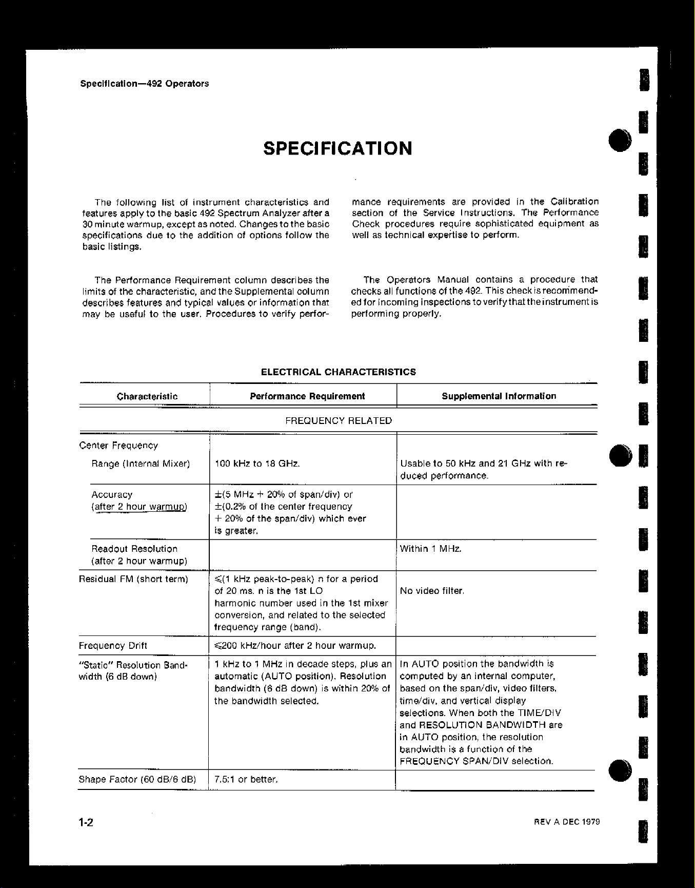
SPECIFICATION ..............................
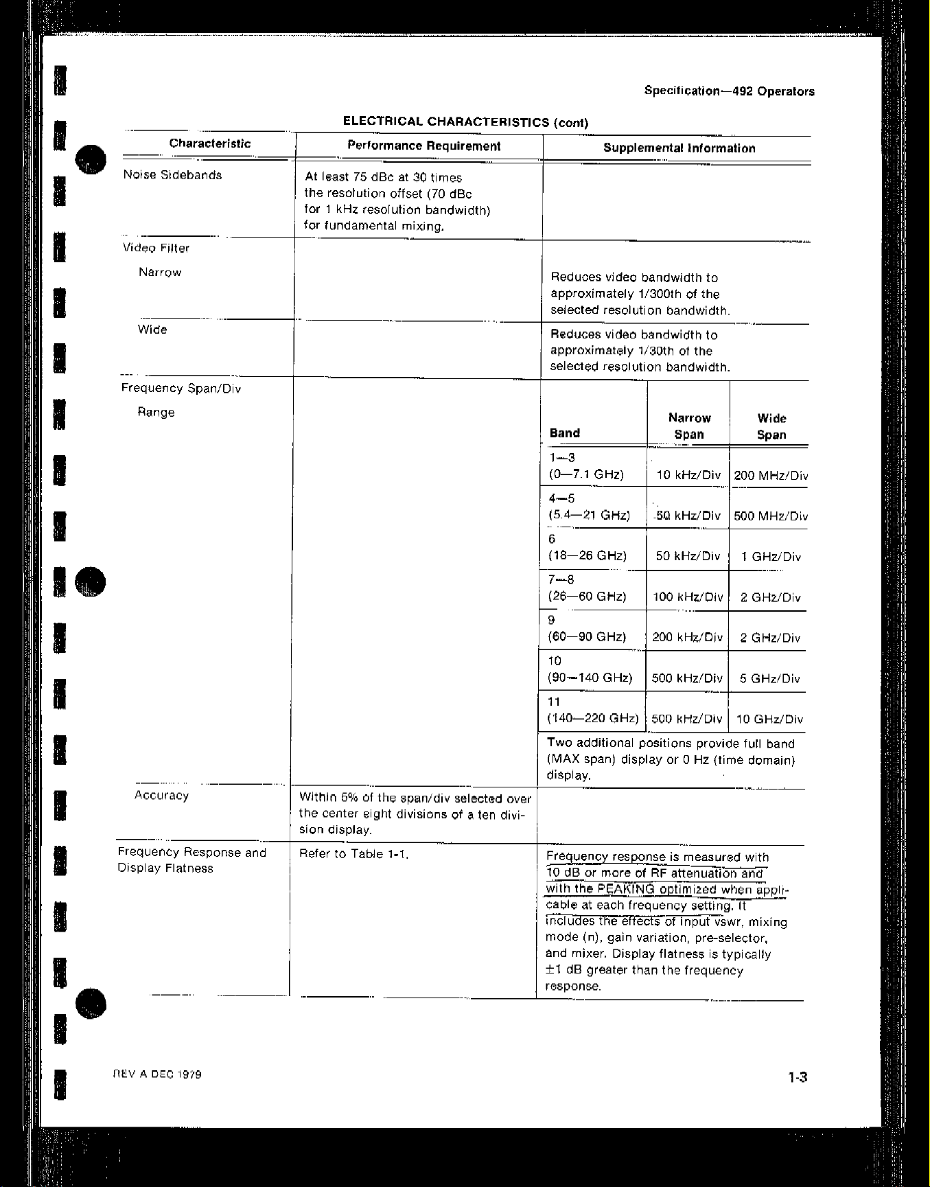
ELECTRICAL CHARACTERISTICS ...............
Frequency Related .........................
Amplitude Related ..............
Input Signal Characteristics .......
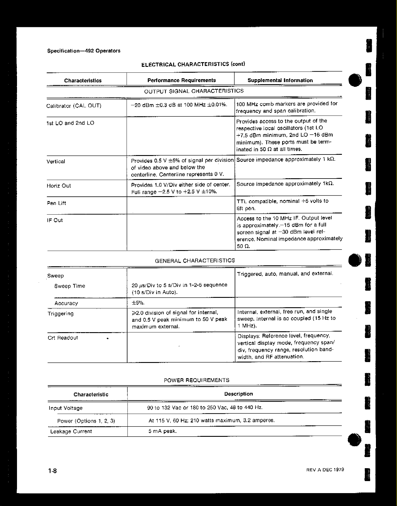
Output Signal Characteristics ......
General Characteristics ..........
Power Requirements ............
ENVIRONMENTAL CHARACTERISTICS
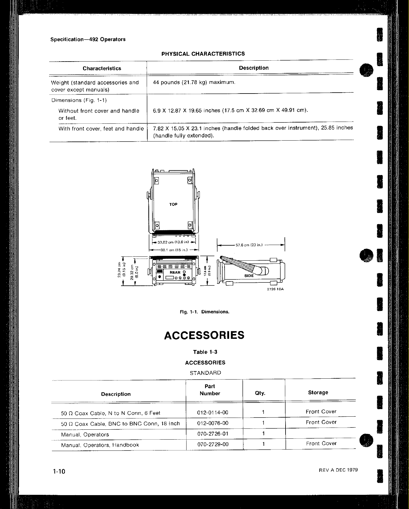
PHYSICAL CHARACTERISTICS ......
ACCESSORIES ....................
OPTIONS ........................
,- Option 1 .......................
I Option 2 .......................
, ... Option 3 .......................
Option fJ .......................
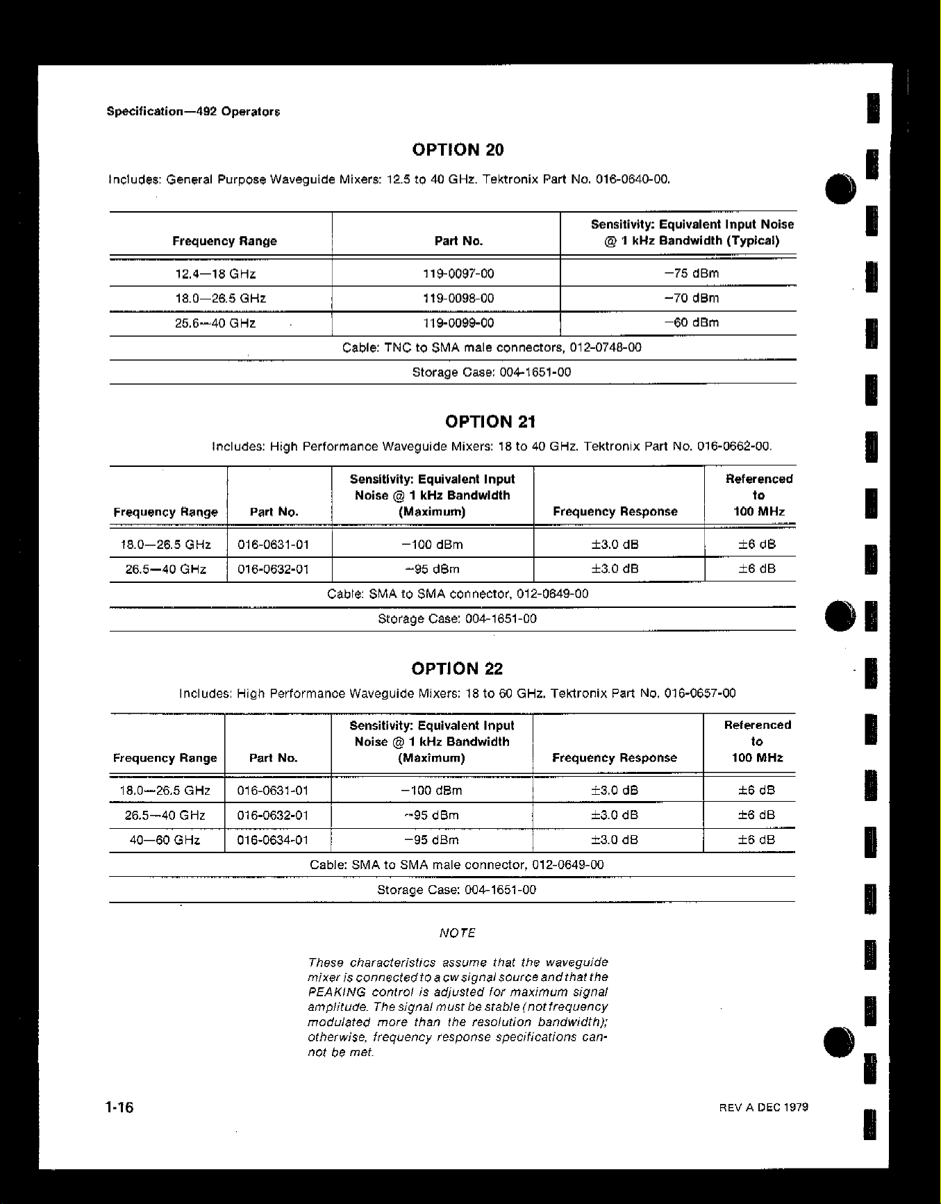
Option 20 ......................
/,Option 21 ......................
Option 22 ......................
Options for Power Cord Configuration
vii
l-l
l-l
l-l
l-l
1-I
1-2
1-2
1-2
1-5
1-7
l-8
l-8
l-8
1-9
i-10
I-IO
1-12
1-12
1-14
1-14
l-15
l-16
l-16
l-16
i-17
SECTION 2 INSTALLATION INSTRUCTIONS
INTRODUCTION .........................
UNPACKING AND INITIAL INSPECTION ........
PREPARATION FOR USE ...................
POWER SOURCE AND POWER REQUIREMENTS
REPACKAGING FOR SHIPMENT .............
Page 4
TABLE OF CONTENTS (cord)
SECTION 3
OPERATION
CONTROLS, INDICATORS, AND CONNECTORS.,
TURN-ON AND PREPARATION FOR USE
1. Initial Turn On
2. Calibrate Center Frequency Readout
3. Calibrate Reference Level and Dynamic Range.
4. Check Span Accuracy and Linearity
FUNCTIONAL OR OPERATIONAL CHECli
1. Check Operation of Front Panel Pushbuttons and Controls
2. Check Frequency Readout Accuracy
3. Check Frequency SpanlDiv Range and Accuracy
4. Check Resolution Bandwidth and Shape Factor
5. Check Reference Level Gain and RF Attenuator Steps
6. Check Sensitivity
7. Check Frequency Drift or Stability,
6. Check Residual FM
9. Digital Storage (Option 2)
GENERAL OPERATING INFORMATION
Crl Light Filters
Intensity Level, Focus. and Beam Alignment
Signal Application
RF INPUT Connector
Amplitude Conversion
Connecting to 75 n Source,
Resolution Bandwidth, Frequency Span, and Sweep Time
Using the Peaking Control
Using the Signal Identifier.
Using the Video Filters
Time Domain Operation
Triggering the Display
Sweeping the Display
Manual Scan of the Spectrum
Reference Level, RF Attenuation, and Vertical Display
Delta A Mode,
Min Noise/Min Distortion
Digital Storage (Option 2)
Waveguide Mixers and External Diplexer
Handling ..........................................
Installation
Operation
Analyzing Signals.
...................................... 3-7
....................................
..................................
...............................
.......................................
..................................... 3-18
.................................
................................
............................
...............................
...............................
..................................
.................................
..................................
...................................
.............................
........................................
................................ 3-23
................................
......................................... 3-24
.........................................
...................................
......................
...................... 3-6
...................... 3-8
.....................
......................
....................... 3-16
.......................
.....................
...............
..............
.............
..............
...................
...... 3-9
......... 3-13
......... 3-19
............
Page
3-l
3-7
3-0
3-9
3-11
3-12
3-13
3-14
3-17
3-17
3-18
3-18
3-18
3-18
3-19
3-19
3-20
3-21
3-21
3-21
3-21
3-22
3-22
3-22
3-22
3-23
3-24
3-24
3-25
3-26
Page 5
TABLE OF CONTENTS (cant)
492 Operators
SECTION 3
I
I
I
1
I
I
SECTION 4 OPTION INFORMATION. ..................................
APPENDIX A
CHANGE INFORMATION
OPERATION (COW)
OPERATIONAL PRECAUTIONS
1. Measurements Outside the Specified Frequency and Tuning Range
Versus Span of the Display
Signal FM ........................................
2.
Correct Trigger Mode. ...............................
3.
4. Level of Pulsed Signals,
5. Level of Continuous Wave Signals
6. Excessive Input Signal Level
No Crt Trace ......................................
7.
Digital Storage Effects on Signal Analyses
8.
9. Stored Display Averaged in Wide Spans
IO. Cold Storage or Power Interrupt Initialization
SERVICE MANUALS
PRODUCTSERVICE
GLOSSARY..
.....................................
.....................................
..........................................
.............................
..............................
.............................. 3-26
.......................
........................... 3-27
................. 3-27
...............
Page
3-26
3-26
3-26
3-26
3-27
3-27
3-27
3-27
3-28
3-28
4-1
A-I
Page 6

492 Operators
LIST OF ILLUSTRATIONS
Page
3-12
3-13
3-14
3-15
Dimensions
International power and plug configuration for the 492
Front panel selectors, controls, and connectors
Rear panel connectors
Crt readout for power-up state
Typical display of calibrator markers in MAX SPAN position
Displays that illustrate how bandwidth and shape factor are determined
Typical display using digital storage with MAX HOLD activated, to measure drift
Displays to illustrate how residual FM is measured
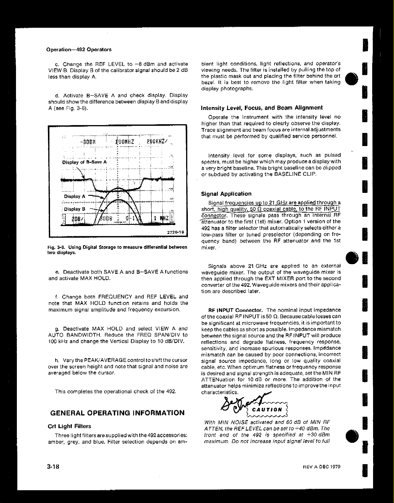
Using digital storage to measure the differential between two events
Volts-dBm-Watts conversion chart for 50 Sk impedance
Circuit of a 75 n to 50 n matching pad (ac coupled)
Graph to illustrate the relationship between dBm, dBmV. and dB@
(matching attenuator included where neCe$$ary)
Integrating the display with the Video Filter
External (Waveguide) mixer installation
Typical display generat,ed by a signal into the waveguide mixer
Identifier mode displays
.................................................
..................
............ .' ..........
.........................................
...................................
..............
......
.....................
........
..................
....................
.......................
..........................
.............................
............
........................................
l-10
1-17
3-1
3-6
3-7
3-7
3-13
3-16
3-17
3-16
3-19
3-20
3-20
3-21
3-24
3-25
3-26
iv
Table
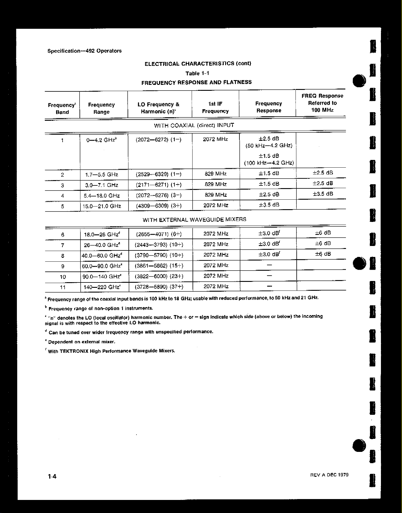
1-1
1-2
1-3
1-4
l-6
2-1
3-l
3-2
3-3
3-4
LIST OF TABLES
Frequency Response and Flatness
Sensitivity versus Bandwidth ........................
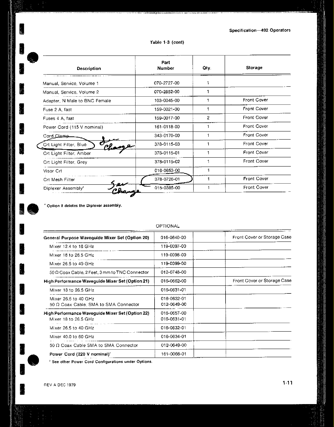
Accessories
Option 1 Frequency Characteristics
Option 1 Sensitivity ..............................
Shipping Carton Test Strength ......................
Span/Div Ranges versus Band and Option
Narrow and Wide Spans verauS Frequency Band ..........
Sensitivity without Preselector .......................
Sensitivity Option 1 ..............................
....................................
....................
...................
..............
.........
......... 1-6
......... l-10
......... 1-12
......... I-13
......... 2-2
......... 3-3
......... 3-12
......... 3-15
......... 3-16
l-4
I
m
I
Page 7

OPERATORS SAFETY SUMMARY
The general safety information in this part of the summary is for both operating and servicing
personnel. Specific warnings and cautions will be found throughout the manual where they
apply. but may not appear in this summary.
TERMS
In This Manual
CAUTION statements identify conditions or practices that could result in damage to the
equipment or other property.
WARNING statements identify conditions or practices that could result in personal injury or
loss of life
As Marked on Equipment
CAUTION indicates a personal injury hazard not immediately accessible as one reads the
marking, or a hazard to property including the equipment itself.
DANGERindicatesapersonalinjuryhazardimmediatelyaccessiblaasonereadsthemarking.
SYMBOLS
In This Manual
indicates where applicable cautionary or other information is to be
As Marked on Equipment
f DANGER - High voltage.
-L Protective ground (earth) terminal.
0
A
Power Source
Thisproductisintendedtooperatefromapowersourcethatwill notapplymorethan250vOltS
rms between the supply conductors or between either supply conductor and ground. A
protective ground connection by way of the grounding conductor in the power cord is
essential for safe operation.
ATTENTION - refer to manual.
Page 8

492 operators
Grounding the Product
This product is grounded through the grounding conductor of the power cord. To avoid
electrical shock, plugthepowercordintoaproperlywired receptacle beforeconnectingtothe
product input or output terminals. A protective ground connection by way of the grounding
conductor in the power cord is essential for safe operation.
Danger From Loss of Ground
Upon loss of the protective-ground connection, all accessible conductive parts (including
knobs and controls that may appear to be insulating) can render an electric shock.
Use the Proper Power Cord
Use only the power cord and connector specified for your product.
Use only a power cord that is in good condition.
For detailed information on power cords and connectors, see Fig. 1-2.
Refer cord and connector changes to qualified service personnel.
Use the Proper Fuse
To avoid fire hazard, use only the fuse of correct type, voltage rating and current rating as
specified in the parts list for your product.
Refer fuse replacement to qualified service personnel.
Do Not Operate in Explosive Atmospheres
To avoid explosion, do not operatethis product in an explosive atmosphere unless it has been
specifically certified for such operation.
Do Not Remove Covers or Panels
To avoid personal injury, do not remove the product covers or panels. Do not operate the
product without the covers and panels properly installed.
Page 9

492 operators
SERVICE SAFETY SUMMARY
FOR QUALIFIED SERVICE PERSONNEL ONLY
Reter also to the preceding Operators Safety Summary.
Do Not Service Alone
DO not perform internal serviceoradjustment of this product unlessanother person capableof
rendering first aid and resuscitation is present.
Use Care When Servicing With Power On
Dangerous voltages exist at several points in this product. To avoid personal injury, do not
touch exposed connections and components while power is on.
Disconnect power before removing protective panels, soldering, or replacing components.
Power source
Thisproductisintendedtooperatefromapowersourcethatwill notapplymorethan250volts
rms between the supply conductors or between either supply conductor and ground. A
protective ground connection by way of the grounding conductor in the power cord is
essential for safe operation.
, DEC 1979
vii
Page 10
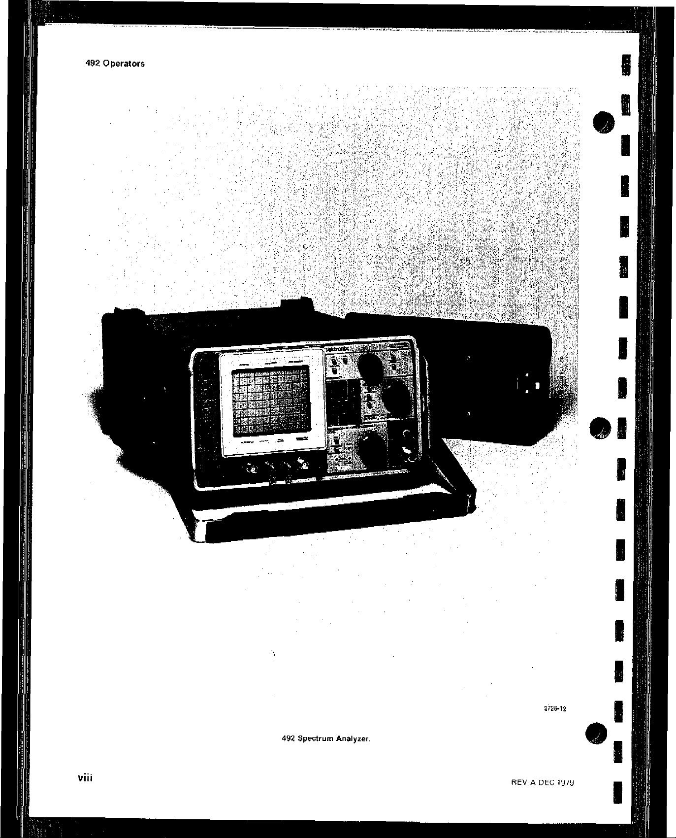
492 operators
Viii
REV A DEC ,979
Page 11
I
II
GENE,RAL INFORMATION AND
SPECIFICATION
GENERAL INFORMATION
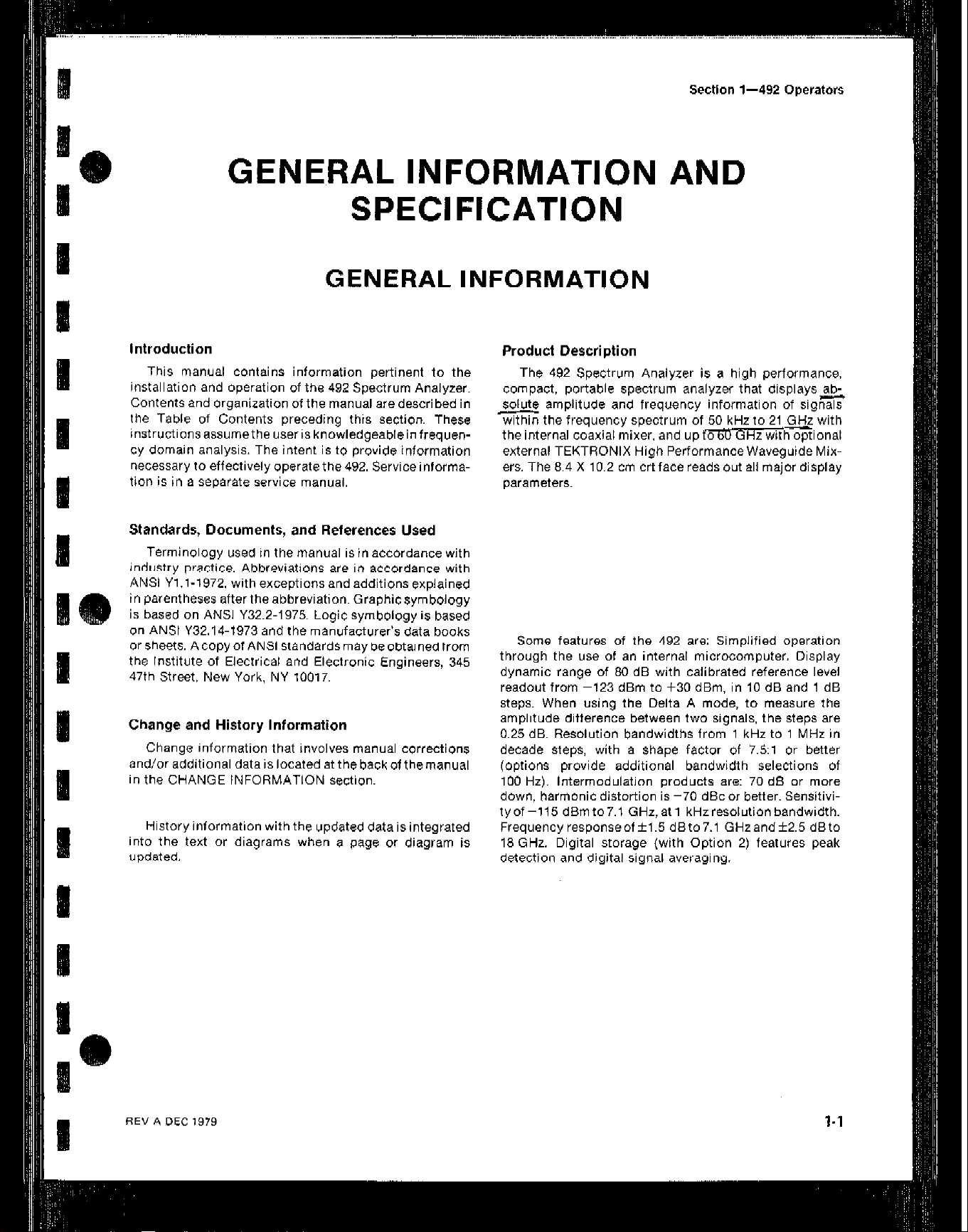
This manual contains information pertinent to the
installation and operation of tha 492 Spectrum Analyzer.
Contents and organization of the manual are descri bed in
the Table of Contents preceding this section. These
instructionsassumetheuserisknowledgeableinfrequency domain analysis. The intent is to provide information
necessary to effectively operate the 492. Service informa-
tion is in a separate service manual
Sectfon l-492 operators
Product Description
The 492 Spectrum Analyzer is a high performance,
compact, portable spectrum analyzer that displays&
Solute amplitude and frequency information of signals
m the frequency spectrum of 50 kHz to 21 GHz with
the internal coaxial mixer, and up tm .r..external TEKTRONIX High Performance Waveguide Mixers. The 8.4 X 10.2 cm crt face reads out all major display
parameters.
Withinnat
R
Standards, Documents, and References Used
Terminology used in the manual is in accordance with
industry practice. Abbreviations are in accorrlnnw with
ANSI Yl.l-1972. with exceptions and addition ,I .,
parentheses after theabbreviation. Graphicsymbology
IS based on ANSI Y32.2.1975. Loqic symboloay is based
on ANSI Y32.14.1973 and the ma~ufa&rer’s data books
or sheets. Acopyof ANSI standardsmay beobtainedfrom
the Institute of Electrical and Electronic Engineers, 345
47th Street, New York. NY 10017.
Change and History Information
Change information that involves manual corrections
and/or additional data is located at the back of themanual
in the CHANGE INFORMATION section.
History information with the updated data isintegrated
into the text or diagrams when a page or diagram is
updated.
1s exolainad
Some features of the 492 are: Simplified operation
through the use of an internal microcomputer. Display
dynamic range of 80 dB with calibrated reference level
readout from -123 dBm to f30 dBm. in 10 dB and 1 dB
steps. When using the Delta A mode, to measure the
amplitude difference between two signals. the steps are
0.25 dB. Resolution bandwidths from 1 kHz to 1 MHz in
decade steps, with a Shape factor of 7.5:1 or better
(options provide additional bandwidth selections of
100 Hz). Intermodulation products are: 70 d0 or more
down, harmonic distortion is -70 dBc or better. Sensitivi-
tyof-115 dBmto7.1 GHz,atl kHzresolutionbandwidth.
Frequencyresponseoff1.5 dBto7.1 GHzandk2.5 dBto
18 GHz. Digital storage (with Option 2) features peak
detection and digital signal averaging.
Page 12
Page 13
Page 14
Page 15

Page 16

Page 17

Page 18
Page 19

Page 20
Page 21
Page 22

Page 23

Page 24

Page 25

Page 26
Page 27

Page 28

Page 29

Page 30

Page 31

Page 32

Page 33

Page 34

Page 35

Page 36

Page 37

Page 38

Page 39

Page 40

Page 41

Page 42

Page 43

Page 44

Page 45

Page 46

Page 47
Page 48

Page 49

Page 50

Page 51

Page 52

Page 53

Page 54

Page 55

Page 56

Page 57

Page 58

Page 59

Page 60

Page 61

Page 62

Page 63

Page 64

Page 65

Page 66

Page 67

 Loading...