

Page 1
TM 11-6625-3135-12
TECHNICAL MANUAL
OPERATOR’S AND ORGANIZATIONAL
MAINTENANCE MANUAL
OSCILLOSCOPE
AN/USM-488
(NSN 6625 -01-1 87-7847)
4
This copy is a reprint which includes current
pages from Change 1.
HEADQUARTERS, DEPARTMENT OF THE ARMY
1 OCTOBER 1986
Page 2

TM 11-6625-3135-12
SAFETY STEPS TO FOLLOW IF SOMEONE IS THE VICTIM OF
ELECTRICAL SHOCK
DO NOT TRY TO PULL OR GRAB THE INDIVIDUAL
IF POSSIBLE, TURN OFF THE ELECTRICAL POWER
IF YOU CANNOT TURN OFF THE ELECTRICAL POWER, PULL,
PUSH, OR LIFT THE PERSON TO SAFETY USING A WOODEN POLE
OR A ROPE OR SOME OTHER INSULATING MATERIAL
SEND FOR HELP AS SOON AS POSSIBLE
AFTER THE INJURED PERSON IS FREE OF CONTACT WITH THE
SOURCE OF ELECTRICAL SHOCK, MOVE THE PERSONA SHORT
DISTANCE AWAY AND IMMEDIATELY START ARTIFICIAL
RESUSCITATION
A
Page 3

TM 11-6625-3135-12
WARNING
HIGH VOLTAGE
is used in the operation of this equipment
DEATH ON CONTACT
may result if personnel fail to observe safety precautions
Never work on electronic equipment unless there is another person nearby who is familiar with the
opera! ion and hazards of the equipment and who is competent in administering first aid. When the
technician is aided by operators, they must be warned about dangerous areas.
A periodic review of safety precautions in TB 385-4, Safety Precautions for Maintenance of
Electrical/Electronic Equipment, is recommended. When the equipment is operated with covers
removed, DO NOT TOUCH exposed connections or components. MAKE CERTAIN you are not
grounded when making connections or adjusting components inside the test instrument.
Be careful not to contact high-voltage connections or 115 volt ac input connections when
installing or operating this equipment.
Whenever the nature of the operation permits, keep one hand away from the equipment to reduce
the hazard of current flowing through the body.
WARNING Do not be misled by the term “low voltage”. Potentials as low as
50 volts may cause death under adverse conditions.
For Artficial Respiration. refer to FM 21-11.
B
Page 4
TM 11-6625-3135-12
Technical Manual
No. 11-6625-3135-12
DEPARTMENT OF THE ARMY
Washington, DC, 1 October 1986
HEADQUARTERS
OPERATOR’S AND ORGANIZATIONAL MAINTENANCE MANUAL
FOR
OSCILLOSCOPE AN/USM-488
(NSN 6625-01-187-7847)
REPORTING ERRORS AND RECOMMENDING IMPROVEMENTS
You can help improve this manual. If you find any mistakes or if you know of a way to improve the
procedures, please let us know. Mail your letter, DA Form 2028 (Recommended Changes to
Publications and Blank Forms), or DA Form 2028-2 located in the back of this manual direct to:
Commander, US Army Communications-Electronics Command and Fort Monmouth, ATTN:
AMSEL-LC-LM-LT, Fort Monmouth, New Jersey 07703-5000. In either case, a reply will be
furnished direct to you.
Page
HOW TO USE THIS MANUAL . . . . . . . . . . . . . . . . . . . . .
CHAPTER 1
INTRODUCTION
. . . . . . . . . . . . . . . . . . . . . . . . . . .
Section I General Information . . . . . . . . . . . . . . . . . . . . . . . . . . . . . . . . . . . . . . . . . . . . . . . . . .
II EQUIPPMENT DESCRIPTION . . . . . . . . . . . . . . . . . . . . . . . . . . . . . . . . . . . . . . . . . . . . . . .
III Technical Principles of Operation . . . . . . . . . . . . . . . . . . . . . . . . . . . . . . . . . . . .
iii
1-1
1-1
1-4
1-10
CHAPTER 2
OPERATING INSTRUCTIONS
. . . . . . . . . . . . . . . . .
Section I Description and Use of Operator’s Controls and Indicators . . . . . . . . . .
II Operator Preventive Maintenance Checks and Services (PMCS) . . . . . .
III Operation Under Usual Conditions . . . . . . . . . . . . . . . . . . . . . . . . . . . . . . . . . . .
IV Operation Under Unusual Conditions
CHAPTER 3
Section I
II
III
IV
V
ORGANIZATIONAL MAINTENANCE INSTRUCTIONS
Repair Parts, Special Tools; (TMDE); and Support Equipment . . . . . .
Service Upon Receipt . . . . . . . . . . . . . . . . . . . . . . . . . . . . . . . . . . . . . . . . . . . . . . . . .
Troubleshooting . . . . . . . . . . . . . . . . . . . . . . . . . . . . . . . . . . . . . . . . . . . . . . . . . . . . . .
Maintenance Procedures . . . . . . . . . . . . . . . . . . . . . . . . . . . . . . . . . . . . . . . . . . . . . .
Preparation for Storage or Shipment
. . . . . . . . . . . . . . . . . . . . . . . . . . . . . . . .
. . . . . . . . . . . . . . . . . . . . . . . . . . . . . . .
APPENDIX A
B
C
D
SUBJECT INDEX
. . . .
2-1
2-2
2-8
2-11
2-44
3-1
3-1
3-2
3-3
3-5
3-12
A-1
B-1
C-1
D-1
I-1
Change 1
i/(ii blank)
Page 5

Page 6

TM 11-6625-3135-12
HOW TO USE THIS MANUAL
This manual tells you about your Oscilloscope AN/USM-488 and
contains instructions about how to use it while testing and maintaining
other equipment.
The technical manual for the equipment you are maintaining will give
you some guidance in the correct method to make certain connections
when testing and troubleshooting with the oscilloscope.
When you first receive your oscilloscope, start at the front of the
manual and go all the way through to the back, and become familiar
with every part of the manual and the oscilloscope.
This manual has an edge index which will help you find specific
information in a hurry. Simply spread the pages on the right edge of the
manual until the printed blocks can be seen. Open the manual where the
block on the edge of the page lines up with your selected topic printed in
the front cover block.
iii
Page 7
TM 11-6625-3135-12
1-0
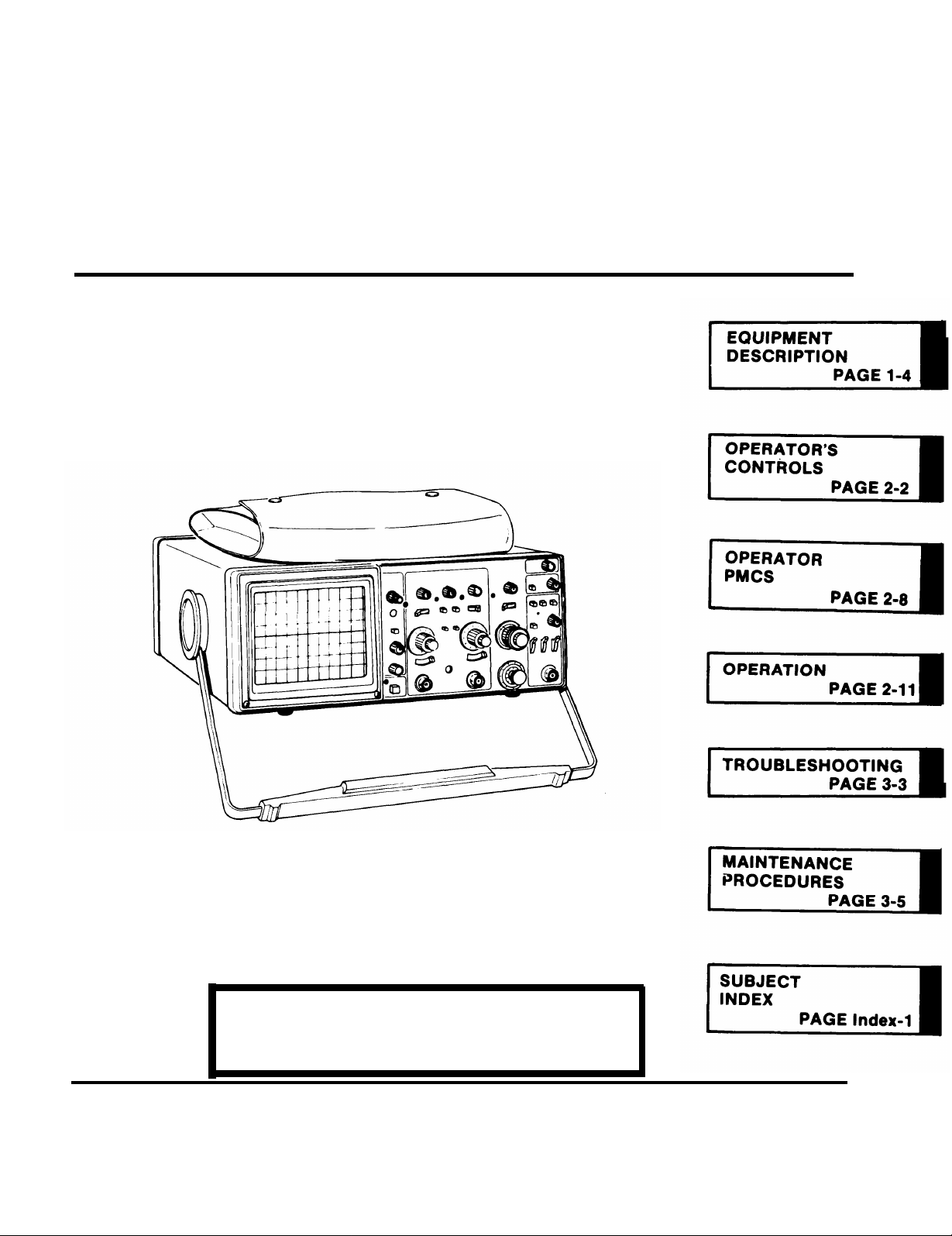
Figure 1-1. Oscilloscope AN/USM-488
Page 8

TM 11-6625-3135-12
CHAPTER 1
INTRODUCTION
Para Page
1-1
Consolidated Index of Army Publications and Blank Forms. . . . . . . . . . . . . . . . .
Destruction of Army Materiel to Prevent Enemy Use . . . . . . . . . . . . . . . . . . . . . . . . . . . .
Euipment Characteristics, Capabilities, and Features. . . . . . . . . . . . . . . . . . . . . . . .
Euipment Data . . . . . . . . . . . . . . . . . . . . . . . . . . . . . . . . . .
Functional Description . . . . . . . . . . . . . . . . . . . . . . . . . . . . . . . . . . . . . . . . . . . . . . . . . . . . . . . .
List of Abbreviations . . . . . . . . . . . . . . . . . . . . . . . . . . . . . . . . . .
Location and Description of Major Components . . . . . . . . . . . . . . . . . . . . . . . . . . . .
Maintenance Forms,Records,and Reports . . . . . . . . . . . . . . . . . . . . . . . . . . . . . . .
Nomenclature Cross-Reference List . . . . . . . . . . . . . . . . . . . . . . . . . . . . . . . . . . . . .
Preparation for Storage or Shipment . . . . . . . . . . . . . . . . . . . . . . . . . . . . .
Reporting Equipment Improvement Recommendations (EIR) . . . . . . . . . . . . . .
Safety, Care, and Handling . . . . . . . . . . . . . . . . . . . . . . . . . . . . . . . . . . . . . . . . . . .
Scope . . . . . . . . . . . . . . . . . . . . . . . . . . . . . . . . . . . .
Warranty Information . . . . . . . . . . . . . . . . . . . . . . . . . . . . . . . . . . . . . . . . . . . . . . . . . . . . . . . .
1-2
1-4
1-11
1-13
1-14
1-10
1-12
1-3
1-7
1-5
1-8
1-6
1-1
1-9
1-1
1-4
1-6
1-10
1-3
1-4
1-1
1-1
1-1
1-1
1-1
1-1
1-2
Section I. GENERAL INFORMATION
1-1.SCOPE
This manual describes the Oscilloscope AN/USM-488 (oscilloscope) and provides instructions for operation, cleaning,
inspection, and maintenance. Testing, troubleshooting, and repair procedures are provided for organizational
maintenance personnel. The oscilloscope (fig. 1-1) is a portable, bench-type oscilloscope designed for general purpose
waveform measurements using single-or dual-trace displays with normal or delayed sweep.
1-2. CONSOLIDATED INDEX OF ARMY PUBLICATIONS AND BLANK FORMS
Refer to the latest issue of DA Pam 25-30 to determine whether there are new editions, changes, or additional publications
pertaining to the equipment.
1-3. MAINTENANCE FORMS, RECORDS, AND REPORTS
a.
Reports of Maintenance and Unsatisfactory Equipment. Department of the Army forms and
procedures used for equipment maintenance will be those prescribed by DA Pam738-750, as contained in Maintenance
Management Update.
b.
Reporting of ltem and Packaging Discrepancies. Fill out and forward SF 364 (Report of Discrepancy
(ROD)) as prescribed in AR 735-11-2/DLAR 4140.55/SECNAVINST 4355.18/AFR 400-54/MCO 4430.3J.
C
.
Transportation Discrepancy Report (TDR) (SF 361). Fill out and forward Transportation Discrepancy
Report (TDR) (SF 361) as prescribed in AR 55–38/NAVSUPINST 4610.33C/AFR 75-18/MCO P4610.19D/DLAR
4500.15.
1-4. DESTRUCTION OF ARMY ELECTRONICS MATERIEL TO PREVENT ENEMY USE
Destruction of Army electronics materiel to prevent enemy use shall be in accordance with TM 750-244-2.
1-5. PREPARATION FOR STORAGE OR SHIPMENT
Storage and shipment procedures are in Chapter 3, Section V.
1-6. SAFETY, CARE, AND HANDLING
Observe all WARNINGS, CAUTIONS, and NOTES in this manual. This equipment can be extremely dangerous if
these instructions are not followed.
1-7. NOMENCLATURE CROSS-REFERENCE LIST
This listing identifies approved nomenclature usage that is different from the official nomenclature:
Common Name
Osccilloscope . . . . . . . . . . . . . . . . . . . . . . . . . .Oscilloscope AN/USM-488
Official Nomenclature
Change 1 1-1
Page 9

TM 11-6625-3135-12
1-8. REPORTING EQUIPMENT IMPROVEMENT RECOMMENDATIONS (EIR)
If your oscillscope needs improvement, let us know. Send us an EIR. You, the user, are the only one who can tell us what
you don’t like about your equipment. Let us know why you don’t like the design or performance. Put it on an SF 368
(Product Quality Deficiency Report). Mail it to: Commander, US Army Communications-Electronics Command and
Fort Monmouth, ATTN: AMSEL-ED-PH, Fort Monmouth, New Jersey 07703-5000. We’ll send you a reply.
1-9. WARRANTY INFORMATION
Oscilloscope AN/USM488 is warranted by Tektronix Inc. for 1 year. The warranty starts on the date of purchase by the
original owner. Report all defects immaterial or workmanship to your supervisor who will take appropriate action through
your organizational maintenance shop.
1-2
Page 10

TM 11-6625-3135-12
1-10. LIST OF ABBREVIATIONS
This list identifies abbreviations, and descriptions that are used in this manual,
Abbreviation
AN/USM. . . . . . . . . . . . . . .
. . . . . . . . . . . . . . . . . . . . . .
AR
. . . . . . . . . . . . . . . . . . .
BII
. . . . . . . . . . . . . . . . . . . . .
BW
. . . . . . . . . . . . . . . . . . . . . .
C
. . . . . . . . . . . . . . . . . . .
cm
crt . . . . . . . . . . . . . . ..
DA . . . . . . . . . . . . . . . . . . .
DOD . . . . . . . . . . . . . . . . .
DISREP . . . . . . . . . . . . .
. . . . . . . . . . . . . . . . . . .
div
EAR . . . . . . . . . . . . . . . . . .
Hz
. . . . . . . . . . . . . . . . . . .
kHz . . . . . . . . . . . . . . . . . .
MAC . . . . . . . . . . . . . . . .
MHz . . . . . . . . . . . . . . . . .
mV
. . . . . . . . . . . . . . . . ..
...... . . . . . . . . . .
ns
NON . . . . . . . . . . . . . . . . .
. . . . . . . . . . . . . . ....
o
pF. .... . . . . ... . . . .
P-P.
. . . . . . . . . . . . . . . . . . . . . .
PMCS . . . . . . . . . . . . . . .
rqr . . . . . . . . . . . . . . . . . . .
. ..... . . . .... . ...
s
sec/div . . . . . . . . . . . . . . .
SIR . . . . . . . . . . . . . . . . .
TAMES . . . . . . . . . . . . .
TIDE . . . . . . . . . . . . . . .
U/M . . . . . . . . . . . . . . . . .
us
..... ... ... ...
uV
. . . . . . . . . .
VITS . . . . . . . . ..... .
Army-Navy/General utility-special-maintenance
Army Regulation
basic issue item
Bandwidth
operator/crew
centimeter
cathode ray tube
Department of the Army
Department of Defense
discrepancy in shipment report
division
equipment improvement recommendation
hertz (formerly cps)
kilohertz
maintenance allocation chart
megahertz
millivolt
nanosecond
National/NATO stock number
organizational maintenance
picofarad
peak-to-peak
preventive maintenance checks and services
required
second
seconds per division
source, maintainability, and recoverability
The Army Maintenance Management System
test, measurement, and diagnostic equipment
unit of measure
microsecond
microvolt
vertical interval test signal
Term
1-3
Page 11

TM 11-6625-3135-12
Section Il. EQUIPMENT DESCRIPTION
1-11. EQUIPMENT CHARACTERISTICS, CAPABILITIES, AND FEATURES
The oscilloscope is a rugged, lightweight, dual-channel instrument allowing visual evaluation of
electrical circuits.
a. Characteristics.
Measures ac voltage and dc voltage
Measures frequency
Measures nondelayed time
Measures rise and fall times
Algebraically adds signals applied to channels 1 and 2
b. Capabilities and Features.
Vertical system provides calibrated deflection factors from 2 inV per division to 5 V per division
Trigger circuits enable stable triggering over full bandwidth of vertical system
Horizontal system provides calibrated sweep speeds from 0.5s per division to 50 ns per division
Horizontal system provides delayed sweep feature
. Magnifier circuit extends maximum sweep speed to 5 ns per division
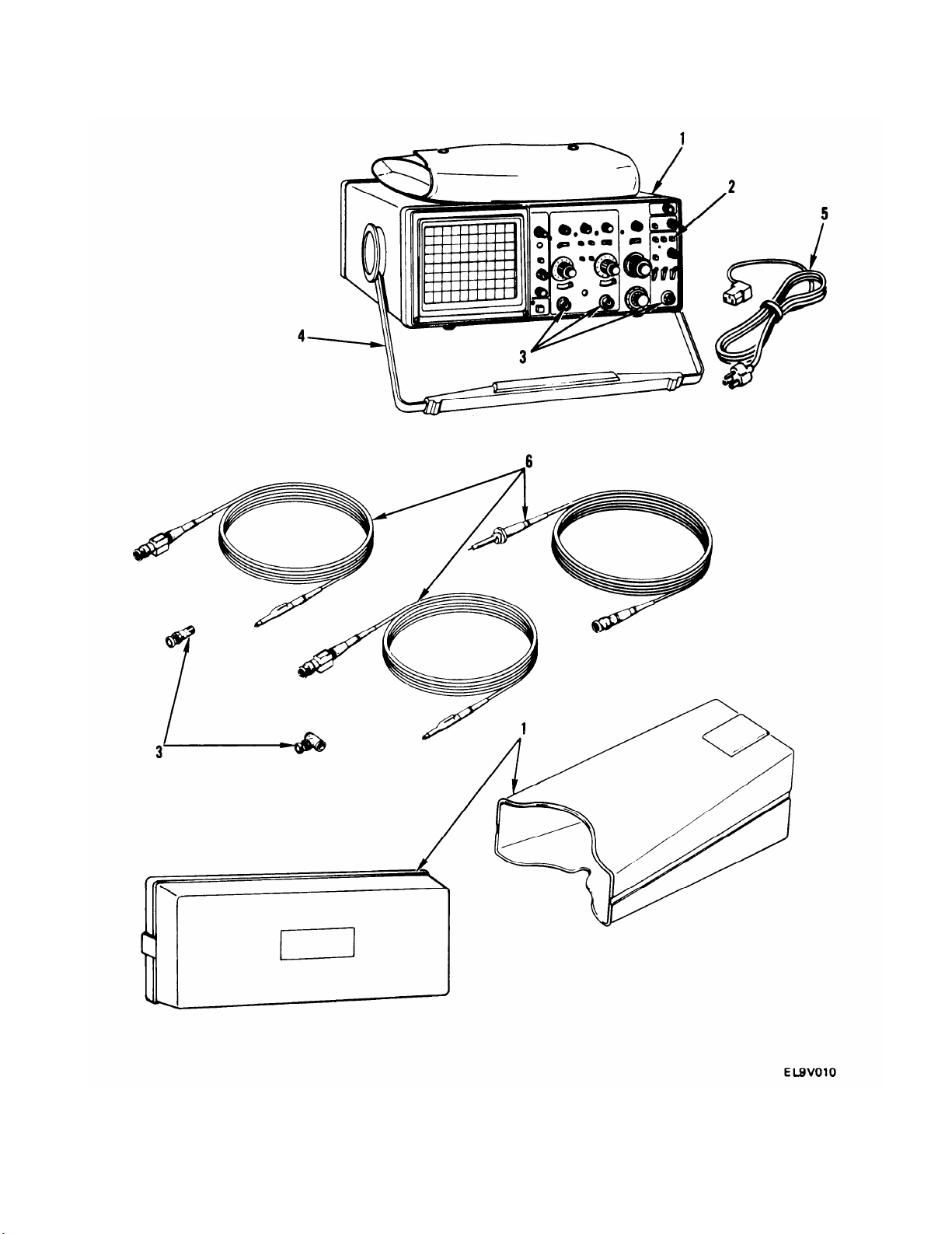
1-12. LOCATION AND DESCRIPTION OF MAJOR COMPONENTS
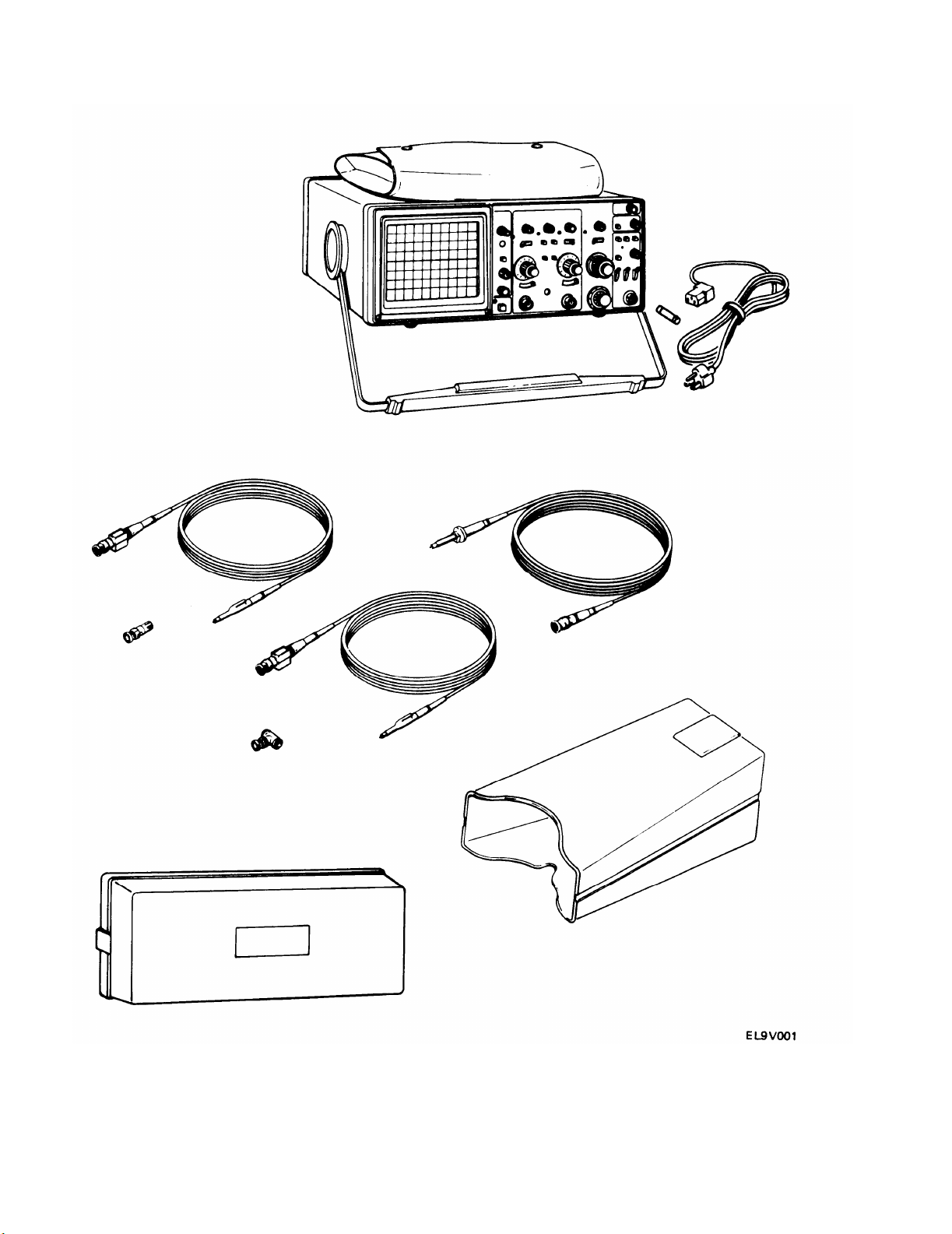
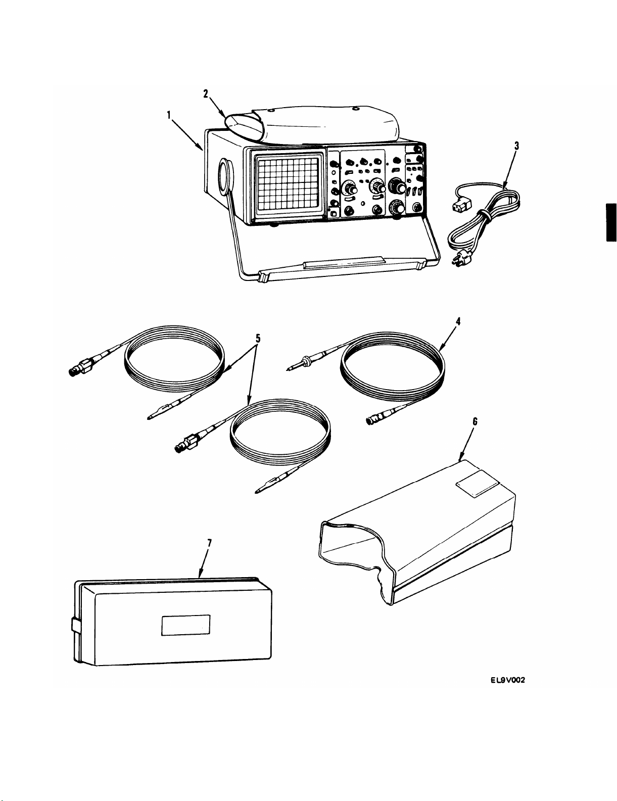
OSCILLOSCOPE (1)
evaluation of electrical circuits. It measures and indicates various electrical characteristics needed to
test and troubleshoot electrical equipment. The handle can be adjusted as a stand.
POUCH (2)
AC POWER CORD (3)
1X PROBE PACKAGE (4) —
— Provides storage for probes and small components.
— A self-contained, multi-range measuring instrument that allows visual
— Provides for operation from the ac power line.
Provides nonattenuated input to oscilloscope.
10X PROBE PACKAGE (5) –
VIEWING HOOD (6) —
COVER (7)
1-4
— Protects crt screen and front panel controls.
Allows operator to view crt display in bright light.
Attenuates input signal by factor of 10.
Page 12
TM 11-6625-3135-12
1-5
Page 13

TM 11-6625-3135-12
1-13. EQUIPMENT DATA
VERTICAL DEFLECTION SYSTEM:
Deflection Factor
Range
Accuracy at 52-95°F(15-350C) ±2%
Accuracy at 32-122°F(0-50
Range of VOLTS/DIV Control . . . . . . . . . . . .
. . . . . . . . . . . . . . . . .
0
C). . . . . . . .. ±3%
2 m V to 5 V per division
Continuously variable between settings, Increases
deflection factor by at least 2.5 to 1
Step Response (Rise Time)
32-95° F (0-35° C)
5 mV to 5 V per Division . . . . . . . . . . . . . . . . . 3.5 ns or less
2 m V per Division . . . . . . . . . . . . . . . . . . . . . . . . 3.9 ns or less
52-122° F (35-50° C)
5 mV to 5 V per Division . . . . . . . . . . . . . . . . . 3.9 ns or less
2 m V per Division, . . . . . . . . . . . . . . . . . . . . . . . 4.4 ns or less
Aberrations (Positive-going Step)
2 m V to 0.5 V per Division . . . . . . . . . . . . . . . . . 4% peak-to-peak
1 V to 5 V per Division . . . . . . . . . . . . . . . . . . . . . 12% peak-to-peak
Bandwidth (-3 dB Point)
32-95° F (0-35° C)
5 m V to5 V per Division ..... . . . . . . . . . . . dc to at least 100 MHz
2 m V per Division . . . . . . . . . . . . . . . . . . . . . . . . dc to at least 90 MHz
95-122° F (35-500C)
5 m V to 5 V per Division . . . . . . . . . . . . . . . . . dc to at least 90 MHz
2 m V per Division . . . . . . . . . . . . . . . . . . . . . . . . dc to at least 80 MHz
AC Coupled Lower Limit . . . . . . . . . . . . . . . . . . . 10 Hz or less at -3 dB
Bandwidth Limiter
. . . . . . . . . . . . . . . . . . . . . . . . . . . .
Upper limits (-3 dB bandpass at 20 MHz, ± 10%)
Chop Mode Switching Rate . . . . . . . . . . . . . . . . . . . 500 kHz ±30%
Input Characteristics
Resistance
.. . . . . . . . . .
Capacitance
. . . . ... . . . . ..... . . . . . . . . . . .
1 Megohm ±2%
20 pF ±2 pF
Maximum Safe Input Voltage
DC Coupled
. . . . . . . . . . . . . . . . . . .. . ..
400 V (dc + peak ac) or 800 V peak-to-peak to 10
kHz or less
AC Coupled . . . . . . . . . . . .. . . . .. . .
400 V (dc + peak ac) or 800 V peak-to-peak to 10
kHz or less
Common Mode Rejection Ratio . . . . . . . . . . . . . . At least 20 to 1 at 80 MHz
Input Current . .. . . .. . . . . . . . . . . . .
1.0 nA or less (0.5 division trace shift at 2 m V per
division)
Trace Shift with VOLTS/DIV Switch
Rotation
. . . . . . . . . . . . .
0.75 division or less
Trace Shift as VOLTS/DIV Variable Control
is Rotated
. . .. . . . . . . . . . . . . . . . . . . .
1.0 division or less
Trace Shift With Invert. . . . . . . .. . .. . .. . .. . 1.5 divisions or less
Channel Isolation
POSITION Control Range .............
. . . . . . . . . . . .
Greater than 100 to 1 at 50 MHz
At least ±11 divisions from graticule center
1-6
Page 14

TRIGGER SYSTEM:
A Trigger Sensitivity
P-P AUTO/TV LINE and NORM Modes
Internal . . . . . . . . . . . . . . . . . . . . . . ..
0.35 division at 10 MHz, 1.0 division at 60 MHz,
1.5 divisions at 100 MHz
External
. . . . . . . . . . . . . . . . . . . . . . . . . . . . . . . . .
35 m V at 10 MHz, 120 m V at 60 MHz, 150 m V at
100 MHz
High-Frequency Rejection . . . . . . . . . . . . . . . .
Attenuates signals above 40 kHz
(-3 dB point at 40 kHz ±25%)
Low-Frequency Rejection . . . . . . . . . . . . . . . .
Attenuates signals below 40 kHz
(--3 dB point at 40 kHz ±25%)
Lowest Useable Frequency in P-P
AUTO Mode . . . . . . . . . . . . . . . . . . . . . . . . . . . . .
TV FIELD Mode . . . . . . . . . . . . . . . . . . . . . . . . . . .
20 Hz with 1.0 division internal or 100 m V external
1.0 division of composite sync
External Trigger Input
Maximum Input Voltage . . . . . . . . . . . . . . . . . . .
Input Resistance . . . . . . . . . . . . . . . . . . . . . . . . . . . .
Input Capacitance . . . . . . . . . . . . . . . . . . . . . . . . . .
AC Coupled . . . . . . . . . . . . . . . . . . . . . . . . . . .
400 V (dc + peak ac) or 800 V ac peak-to-peak
1 Megohm ±2%
20 pF ±2.5 pF
10 Hz or less at lower -3 dB point
Level Control Range
A TRIGGER (Normal)
INT . . . . . .
. . . . ... . . . . . . . . . . . . . . .
. . . . . . . . . .
Can be set to any point of the trace that can be
displayed
EXT. DC
EXT. DC 10
. . . . . . . . . . . . . . . . . . . . . . .... . . . . . .
. . . . . . . . . . . . . . . . . . . . . . . . . . .
B TRIGGER (Internal) . . . . . . . . . . . . . . . . . . . . .
At least+ 1.6 V (3.2 V peak-to-peak)
At least ±16 V (32 V peak-to-peak)
Can be set to any point of trace that can be
displayed
VAR HOLDOFF Control
. . . . . . . . . . . . . . . . . .
Increases A sweep holdoff time by at least a
factor of 10
TM 11-6625-3135-12
TRIGGER VIEW SYSTEM:
Deflection Factor
Internal
. . . . . . . . . . . . . . . . . . . . . . . . . . . . ...... .
Same as vertical
External
AC and DC
. . . . . . . . . . . . . . . . . . . ...... ...
DC 10 . . . . . . . . . . . . . . . . . . . . . . . . . . . . . . . . . .
Accuracy . . . . . . . . . . . . . . . . . . . . . . . . . . . . . ...
100 m V per division
1 V per division
±20%
Delay Difference Between EXT INPUT and
Either Vertical Channel . . . . . . . . . . . . . . ...
Less than 2.0 ns
1-7
Page 15

TM 11-6625-3135-12
HORIZONTAL DEFLECTION SYSTEM:
Sweep Rate Calibrated Range
A sleep . . . . . . . . . . . . . . . . . . . . . . . . . . . . . . . . . . . .
0.5 second to 0.05 us per division. X10 magnifier
extends maximum sweep speed to 5 ns per
division
B Sweep . . . . . . . . . . . . . . . . . . . . . . . . . . . . . . . . . . . . .
50 ms to0.05us per division. X10 magnifier
extends maximum sweep speed to 5 ns per
division
Sweep Rate Accuracy at 59-95° F (15-35° C)...
Sweep Rate Accuracy at 32-122° F (0-50° C)...
POSITION Control Range . . . . . . . . . . . . . . . . . . . .
±2% unmagnified, ±3% magnified
±3% unmagnified, ±4% magnified
Start of sweep to 10th division will position past
center vertical graticule line in X1 or 100th
division in X10
Sweep Linearity . . . . . . . . . . . . . . . . . . . . . . . . . . . . . . . ±5%
Variable Control Range . . . . . . . . . . . . . . . . . . . . . . .
Continuously variable between calibrated
settings. Reduces A and B sweep speeds by at
least a factor of 2.5
Sweep Length . . . . . . . . . . . . . . . . . . . . . . . . . . . . . . . . . Greater than 10 divisions
A/B SWP SEP Range . . . . . . . . . . . . . . . . . . . . . . . . ±3.5 divisions or greater
Delay Time . . . . . . . . . . . . . . . . . . . . . . . . . . . . . . . . . . . .
Dial Control Range . . . . . . . . . . . . . . . . . . . . . . . . .
Jitter . . . . . . . . . . . . . . . . . . . . . .
. . . . . . . . . . . . . . . . . .
Applies to 0.5 us per division and slower
<0.5 + 300 ns to >10 divisions
0.005% of the maximum delay time
Time Measurement Accuracy
59-95° F (15-350 C) . . . . . . . . . . . . . . . . . . . . . . . . ±1%+ 0.01 major dial division
32-122° F (0-50
0
C) . . . . . . . . . . . . . . . . . . . . . . . . ±2%+ 0.01 major dial division
X-Y OPERATION:
Deflection Factors . . . . . . . . . . . . . . . . . . . . . . . . . . . . .
Same as vertical deflection system (with
VOLTS/DIV variable controls in CAL detent)
Accuracy
X-Axis at 59-95° F (15-35
X-Axis at 32-122° F (0-50
Y-Axis . . . . . . . . . . . . . . . . . . . . . . . . . . . . . . . . . . . . . .
0
C) . . . . . . . . . . . . . . . ±3%
0
C) . . . . . . . . . . . . . . . ±4%
Same as vertical deflection system
Bandwidth (--3 dB Point)
X-Axis . . . . . . . . . . . . . . . . . . . . . . . . . . . . . . . . . . . . . . dc to at least 2.5 MHz
Y-Axis . . . . . . . . . . . . . . . . . . . . . . . . . . . . . . . . . . . . . .
Same as vertical deflection system
Phase Difference Between X- and Y-Axis
Amplifiers, . . . . . . . . . . . . . . . . . . . . . . . . . . . . . . . . . . ±3%from dcto150kHz
AMPLITUDE CALIBRATOR:
Output Voltage of AMP CAL Connector . . . . . 0.5V ±2%
Repetition Rate................ . . . . . . . . . . . 1 kHz ±20%
Z-AXIS INPUT:
Sensitivity . . . . . . . . . . . . . . . . . . . . . . . . . . . . . . . . . . . . .
5 V causes noticeable modulation. Positive-going
input decreases intensity. Useable frequency range
is dc to 20 MHz.
Maximum Safe Input Voltage . . . . . . . . . . . . . . . . .
30 V (dc + peak) or 30 V ac peak-to-peak at
1 kHz or less
Input Resistance . . . . . . . . . . . . . . . . . . . . . . . . . . . . . . . 10 kilo hms ±10%
1-8
Page 16

POWER SOURCE:
Line Voltage Ranges . . . . . . . . . . . . . . . . . . . . . . . . . .
Line Frequency . . . . . . . . . . . . . . . . . . . . . . . . . . . . . . . .
Maximum Power Consumption . . . . . . . . . . . . . . .
Line Fuse . . . . . . . . . . . . . . . . . . . . . . . . . . . . . . . . . . . . . .
90 V ac to 250 V ac
48 to 440 Hz
40 W (70 VA)
1.0 A, 250 V, Slow-blow
CATHODE RAY TUBE:
Display Area . . . . . . . . . . . . . . . . . . . . . . . . . . . . . . . . . .
Standard Phosphor
. . . . . . . . . . . . . . . . . . . . . . . . . . .
Nominal Accelerating Voltage . . . . . . . . . . . . . . . . .
80mmx100mm
P31
14 kV
ENVIRONMENTAL CHARACTERISTICS:
Operating Temperature . . . . . . . . . . . . . . . . . . . . . . .
Nonoperating Temperature . . . . . . . . . . . . . . . . . . .
Operating Altitude . . . . . . . . . . . . . . . . . . . . . . . . . . . .
32-122° F (0-50° C)
-67 to +167°F (--55 to + 75°C)
Up to 15,000 ft (4,500m). Maximum temperature
decreased 1° C per 1,000 ft above 5,000 ft
Nonoperating Altitude . . . . . . . . . . . . . . . . . . . . . . . .
Operating Humidity
. . . . . . . . . . . . . . . . . . . . ... . . .
Nonoperating Humidity . . . . . . . . . . . . . . . . . . . . . . .
Vibration (Operating) . . . . . . . . . . . . . . . . . . . . . . . . .
To 50,000 ft (15,000 m)
95% at 86-122° F (30-50° C)
95% at 86-140° F (30-60° C)
Can withstand total displacement of 0.01 5 inch
p-p (2.4 g’s at 55 Hz) along all three axes, with
frequency varied from 10 Hz to 55 Hz, for period
of 15 minutes
Electromagnetic Interference . . . . . . . . . . . . . . . . . .
Meets requirements of MIL STD-461B Pt 4
TM 11-6625-3135-12
PHYSICAL CHARACTERISTICS:
Weight with Accessories . . . . . . . . . . . . . . . . . . . . . . .
Weight without Accessories . . . . . . . . . . . . . . . . . . .
Domestic Shipping Weight . . . . . . . . . . . . . . . . . . . .
Height with Empty Pouch . . . . . . . . . . . . . . . . . . . . .
Height without Pouch . . . . . . . . . . . . . . . . . . . . . . . . .
Width with Handle
. . . . . . . . . . . . . . . . . . . . . . . . . . . .
Width without Handle . . . . . . . . . . . . . . . . . . . . . . . .
Length with Front Cover . . . . . . . . . . . . . . . . . . . . . .
Length without Front Cover.. . . . . . . . . . . . . . . . .
Length with Handle Extended . . . . . . . . . . . . . . . . .
20.0 lb (9.1 kg)
13.5 lb (6.1 kg)
24.1 lb (10.9 kg)
5.9 in. (150 mm)
5.4 in. (137 mm)
14.2 in. (360 mm)
12.9 in. (328 mm)
17.5 in. (445 mm)
17.3 in. (440 mm)
20.1 in. (511 mm)
1-9
Page 17

TM 11-6625-3135-12
Section Ill. TECHNICAL PRINCIPLES OF OPERATION
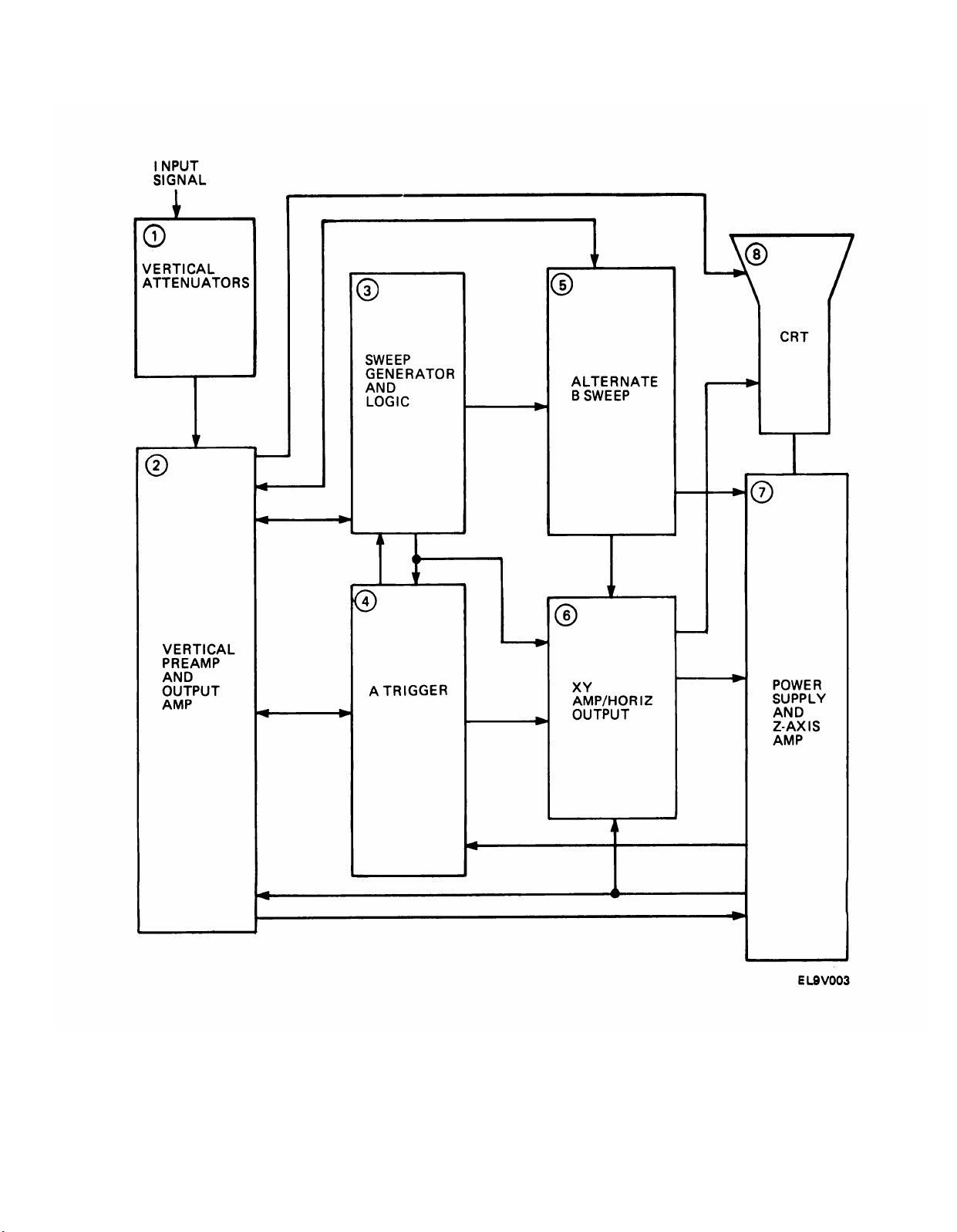
1-14. FUNCTIONAL DESCRIPTION
The following is a basic functional description of the oscilloscope. Refer to fig. 1-2 for a block
diagram.
There are two vertical attenuators (one for each channel). The attenuator circuits provide
control of input coupling, vertical deflection factor, and variable volts-per-division gain. An
invert circuit in the channel 2 attenuator allows you to invert the channel 2 input signal.
The vertical preamp and output circuit amplifies the input signals. This makes the signal level
high enough for vertical deflection of the electron beam in the crt. The dynamic range of the
amplifier can be limited with the beam find switch. The amplifier also intensifies the trace and
limits horizontal deflection.
The A sweep generator and logic circuit produces a linear voltage ramp for horizontal
deflection of the crt beam. The sweep generator also produces signals that generate correct
timing of the crt unblinking and intensity levels.
The A trigger circuitry uses either an internal signal, external trigger, or ac line trigger signal to
develop a gate signal for the A sweep generator. The B trigger circuitry uses only the internal
trigger signal to gate the B signal generator.
The alternate B sweep circuitry produces a linear voltage ramp that is amplified by the
horizontal amplifier. This provides the B sweep horizontal deflection on the crt. The alternate
B sweep circuitry also produces sweep-switching signals that control the display of the A and
B sweeps, and gate signals used to establish the crt unblinking and intensity levels for the A
intensified and B sweep displays.
The X-Y amplifier amplifies the channel 1 signal from the internal circuit and applies it to the
horizontal amplifier. The horizontal amplifier provides output signals to drive the crt
horizontal deflection plates.
The power supply converts ac power-line voltage into voltages needed for oscilloscope
operation. The Z-axis amplifier uses several input signal sources to control the crt intensity
level.
The crt provides a visual display of the electrical properties of the circuit or signal under
examination.
1-10
Page 18
TM 11-6625-3135-12
Figure 1-2. AN/USM-488 Oscilloscope Block Diagram
1-11/(1-12 Blank)
Page 19

Page 20

CHAPTER 2
OPERATING INSTRUCTIONS
TM 11-6625-3135-12
Para
General Operator Preventive Maintenance Checks and Services . . . . . . . . .
Operating Procedures . . . . . . . . . . . . . . . . . . . . . . . . . . . . . . . . . . . . . . . . . . . . . . . . . . . . . .
Operation in Unusual Weather . . . . . . . . . . . . . . . . . . . . . . . . . . . . . . . . . . . . . . . . . . . . .
PMCS Table . . . . . . . . . . . . . . . . . . . . . . . . . . . . . . .
. . . . . . . . . . . . . . . . . . . . . . . . . . . . . . . .
2-1
2-3
2-4
2-2
Page
2-8
2-11
2-44
2-8
2-1
Page 21
TM 11-6625-3135-12
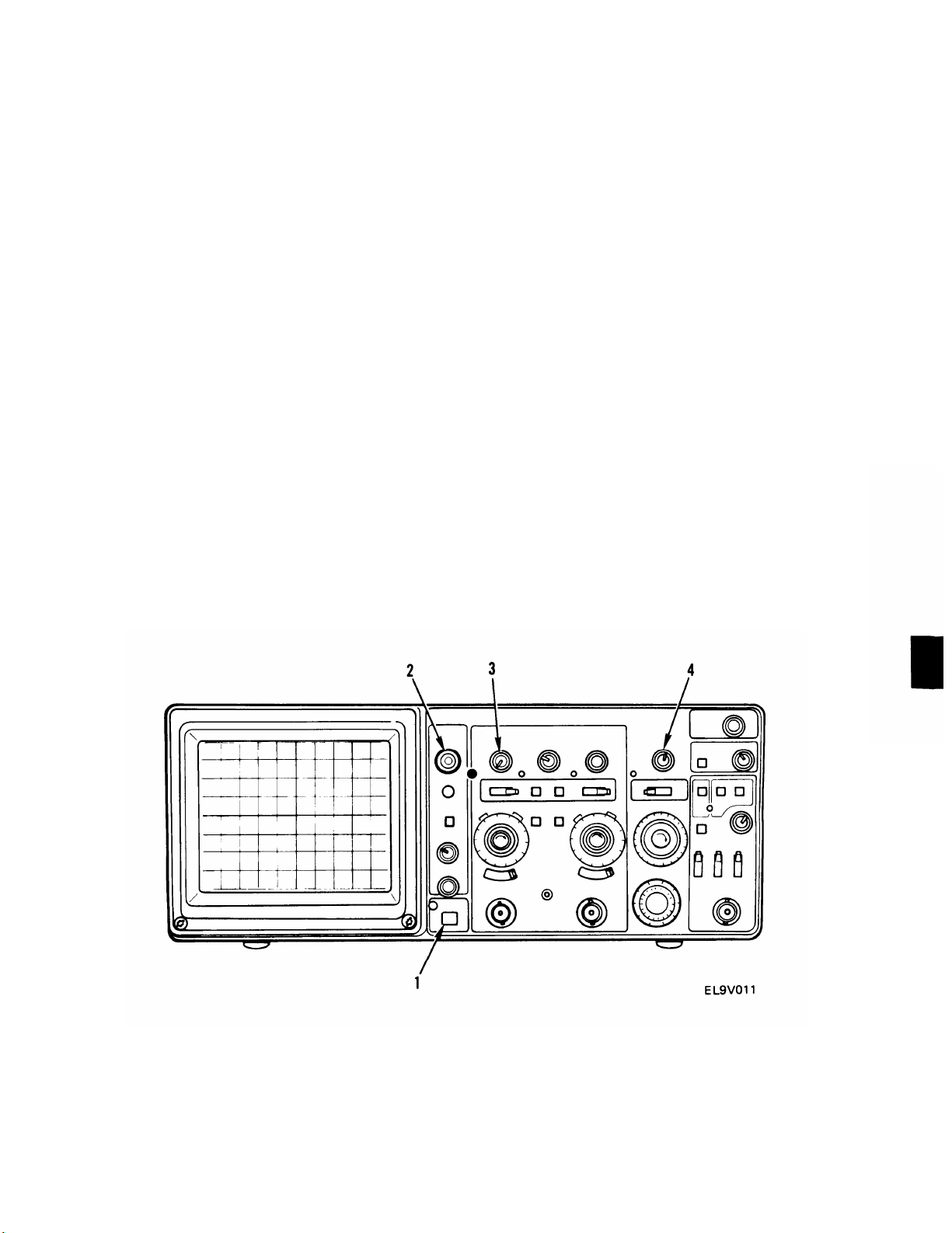
Section I. DESCRIPTION AND USE OF OPERATOR’S CONTROLS
AND INDICATORS
Key
1
2
3
4
5
6
7
Control Or Indicator
Cathode Ray Tube
A INTENSITY
Control
B INTENSITY
Control
TRACE ROTATION
Control
BEAM FIND Switch
SCALE ILLUM
Control
FOCUS Control
Function
Provides visual display of electrical properties of circuit
under examination
Controls brightness of A sweep trace
Controls brightness of B sweep trace
Screwdriver adjustment used to align trace with horizontal
graticule line
When held depressed, compresses display to within graticule
area to aid in locating off-screen displays
Adjusts brightness of graticule illumination
Adjusts for optimum display definition
2-2
8
POWER Switch
POWER Indicator
9
Turns oscilloscope power on and off
When illuminated, indicates power applied to oscilloscope
Page 22
TM 11-6625-3135-12
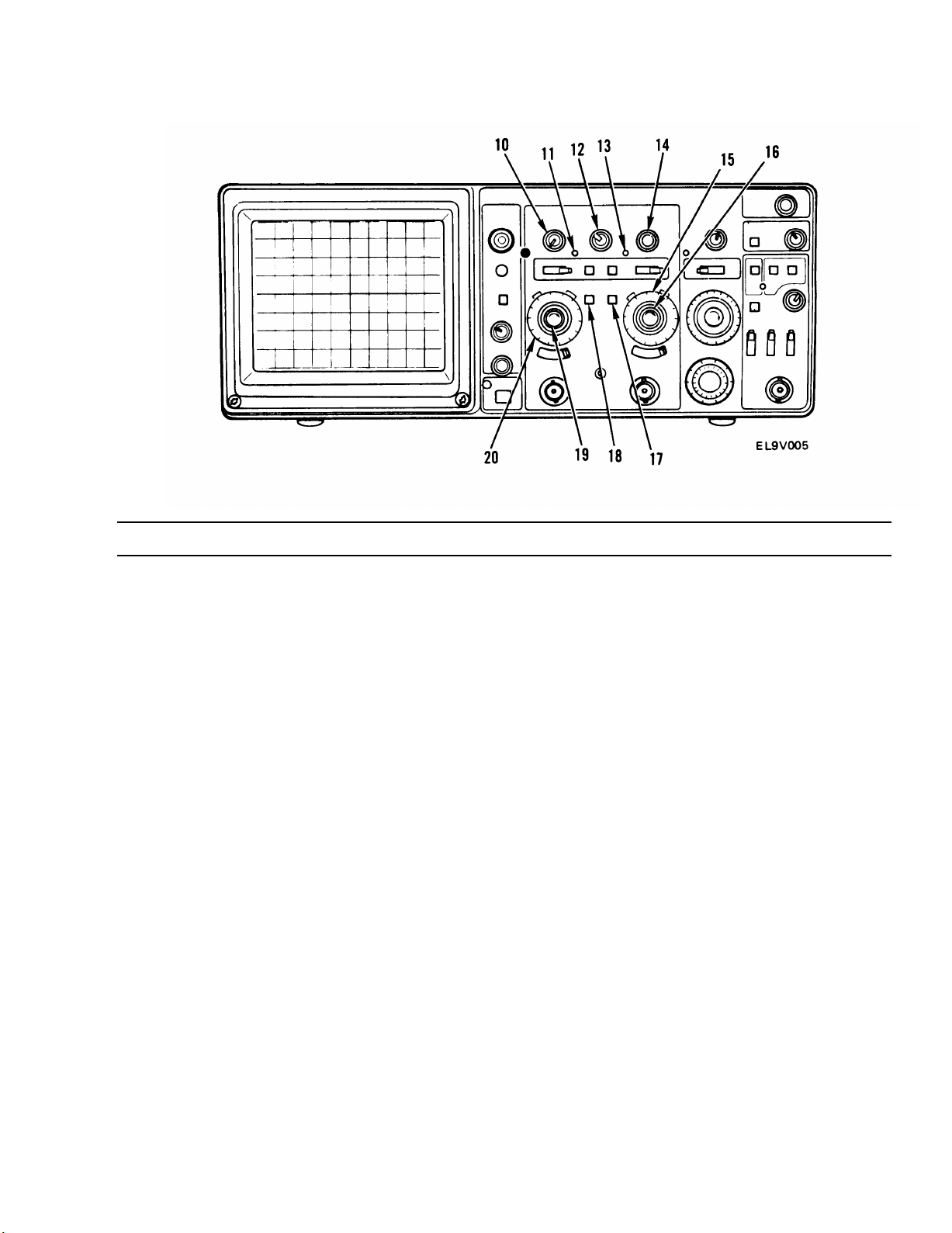
Key
10
11
12
13
14
15
16
17
18
Control Or Indicator
POSITION Control
UNCAL Indicator
A/B SWP SEP Control
UNCAL Indicator
POSITION Control
CH 2 VOLTS/DIV
Switch
CH 2 VOLTS/DIV
Variable Control
BW LIMIT Switch
TRIG VIEW Switch
Function
Controls vertical position of channel 1 display
When illuminated, indicates channel 1 VOLTS/DIV control
not in calibrated position
Vertically positions B sweep trace with respect to A sweep
trace when HORIZONTAL ALT mode is selected
When illuminated, indicates channel 2 VOLTS/DIV control
not in calibrated position
Controls vertical position of channel 2 display
Used to select channel 2 vertical deflection factor
When rotated out of detent, provides variable, uncalibrated
deflection factors between calibrated settings of channel 2
VOLTS/DIV switch
When depressed, limits bandwidth of vertical amplifier and
A trigger system to approximately 20 MHz
While held in, sample of signal present in A trigger amplifier
displayed on crt
19
CH 1 VOLTS/DIV
Variable Control
20
CH 1 VOLTS/DIV
Switch
When rotated out of detent, provides variable, uncalibrated
deflection factors between calibrated settings of channel 1
VOLTS/DIV switch
Used to select channel 1 vertical deflection factor
2-3
Page 23
TM 11-6625-3135-12
Key
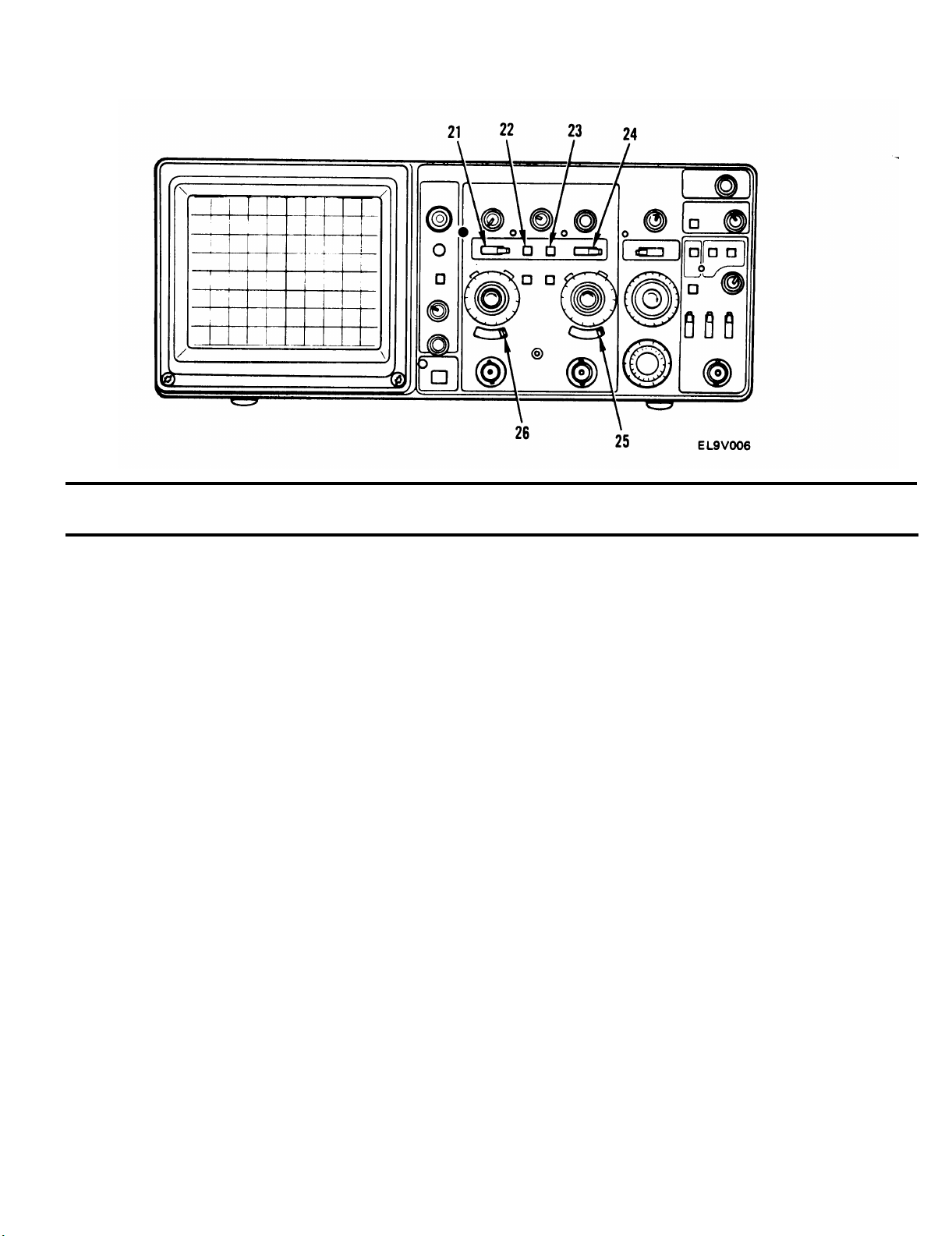
21
Control Or Indicator
VERTICAL MODE
CH 1/BOTH/CH
Switch
22 CH 1 TRIGGER
SOURCE Switch
22-23 COMPOSITE
23
CH 2 TRIGGER
SOURCE Switch
VERTICAL MODE
24
ADD/ALT/CHOP
Switch
Function
When set to CH 1, selects only channel 1 input signal
2
for display. When set to BOTH, selects both channel 1
and channel 2 input signals for display. When set to CH 2,
selects only channel 2 input signal for display
When depressed, selects signal applied to CH 1 OR X
INPUT connector as trigger source
When CH 1 and CH 2 switches are either both depressed or
both released, composite trigger source is selected, Trigger
source is then determined by signals selected for display by
the VERTICAL MODE switches
When depressed, selects signal applied to CH 2 OR Y
INPUT connector as trigger source
When set to ADD, displays algebraic sum of channel 1
and channel 2 input signals. When set to ALT, displays
channel 1 and channel 2 input signals alternately at end of
each trace. When set to CHOP, displays channel 1 and
channel 2 input signals alternately during sweep time
2-4
25
26
AC/GND/DC Switch
AC/GND/DC Switch
Three-position switch to select method of coupling input
signal to channel 2 deflection system. It also establishes DC
ground reference line on crt.
Three-position switch to select method of coupling input
signal to channel 1 deflection system. It also establishes DC
ground reference line on crt.
Page 24
TM 11-6625-3135-12
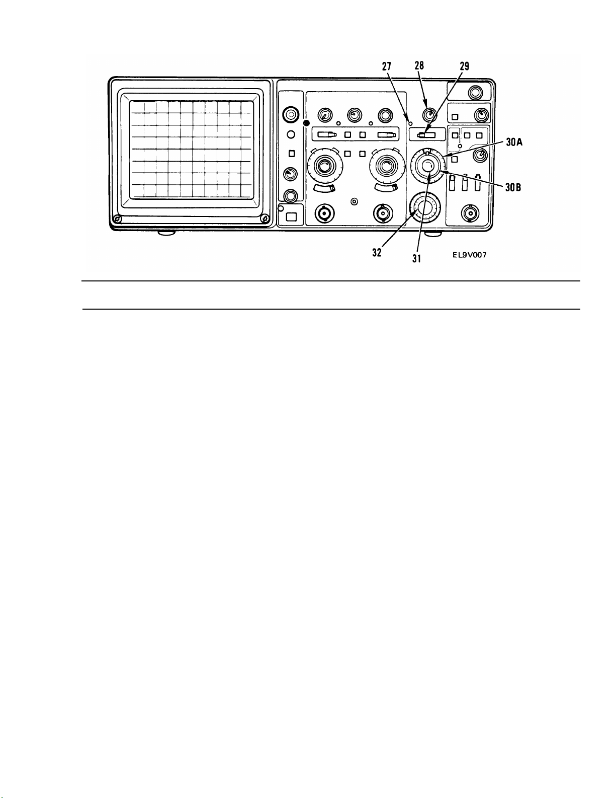
Key
27
28
29
30A
30B
Control Or Indicator
UNCAL Indicator
POSITION Control
HORIZONTAL MODE
A/ALT/B Switch
A SEC/DIV Switch
B SEC/DIV Switch
Function
When illuminated, indicates SEC/DIV variable control is
not in calibrated position
Moves A sweep and B sweep displays horizontally and
horizontally positions X-axis in X-Y mode of operation
Determines mode of operation for horizontal deflection
system. When set to A, horizontal deflection is provided by
A sweep generator. When set to ALT, display alternates
between A sweep and B delayed sweep. When set to B,
horizontal deflection is provided by B sweep generator
Used to select sweep speeds for A and B sweep generators in
a 1, 2, 5 sequence. To lock A and B sweeps together, pull the
B SEC/DIV switch out and align the pointer on the B
SEC/DIV switch between the two markers on the A
SEC/DIV switch, then release the switch. If the two
switches are not locked together, B sweep can be delayed.
Setting A SEC/DIV switch to X-Y locks the A sweep in
horizontal mode.
31
SEC/DIV Variable
Control and X10
Multiplier Switch
B DELAY TIME
32
POSITION Control
Provides continuously variable, uncalibrated sweep speeds.
Pulling control out actuates X 10 magnifier switch, which
expands crt display by a factor of 10
Selects amount of delay time between start of A sweep and
start of B sweep. Delay time is variable from 0.5 to 10 times
A SEC/DIV switch setting
2-5
Page 25
TM 11-6625-3135-12
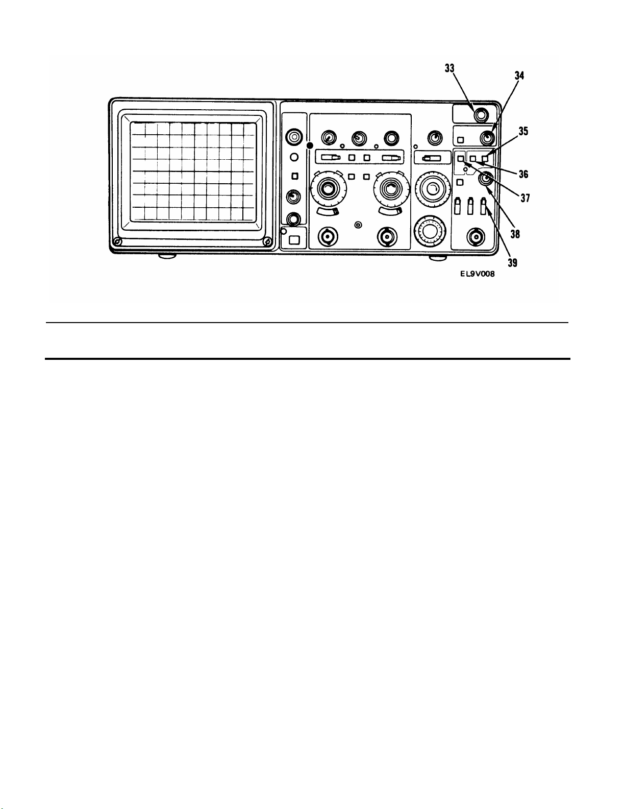
Key
33
34
35
35-36
36
37
Control Or Indicator
VAR HOLDOFF
Control
B TRIGGER LEVEL
Control
A TRIGGER NORM
Switch
TV FIELD
A TRIGGER
P-P AUTO/TV LINE
Switch
A TRIGGER SGL SWP
RESET Switch
Function
Provides continuous control of hold off time between sweeps
and increases hold off time by at least a factor of 10
Selects amplitude point
on trigger signal at which B sweep is
triggered
When depressed,
sweep
is initiated when adequate trigger
signal is applied
Depressing both P-P
permits triggering on
AUTO and NORM pushbuttons
television field signals
Permits triggering on waveforms and television lines having
repetition rate of at least 20 Hz. Sweep free-runs in absence
of adequate trigger signal
When momentarily depressed, arms A trigger circuit for
single-sweep display
2-6
A TRIGGER LEVEL
38
Control
39
A EXT
COUPLING
Switch
Selects amplitude point on trigger signal at which A sweep is
triggered
Three-position switch that determines method used to
couple external signals from EXT INPUT connector to A
trigger circuit
Page 26

TM11-6625-3135-12
Key
40
Control Or Indicator
B TRIGGER SLOPE
Switch
TRIG’D/READY
41
Indicator
42 A TRIGGER SLOPE
Switch
43
A SOURCE Switch
44 A TRIG BW Switch
Function
Selects slope of signal that triggers B channel sweep
Illuminates when either P-P AUTO or NORM trigger mode
is selected
Selects slope of signal that triggers A channel sweep
Three-position switch that determines source of trigger
signal coupled to input of A trigger circuit. When set to
INT, permits triggering on signal applied to CH 1 OR X
connector or CH 2 OR Y connector. When set to LINE,
selects ac line voltage as trigger signal. When set to EXT,
permits triggering on signals applied to EXT INPUT
connector
Three-position switch that selects trigger bandpass
frequencies for A trigger circuit. When set to FULL, allows
all frequency components to pass. When set to HF REJ,
attenuates all trigger signals above approximately 40 kHz.
When set to LF REJ, attenuates all trigger signals below
approximately 40 kHz
2-7
Page 27

TM 11-6625-3135-12
Section Il. OPERATOR PREVENTIVE MAINTENANCE CHECKS
AND SERVICES (PMCS)
2-1. GENERAL
Operator Preventive Maintenance Checks and Services (PMCS) is the required inspection and care
of your equipment necessary to keep it in good operating condition.
a. Before You Operate.
Always keep in mind the CAUTIONS and WARNINGS. Perform your
before - PMCS.
b. While YOU Operate. Always keep in mind the CAUTIONS and WARNINGS. Perform your
during - PMCS.
c. After Y
OU Operate. Be sure to perform your after-operation PMCS.
d. If Your Equipment Falls to Operate. Troubleshoot with proper equipment. Report any
deficiencies using the proper forms. See DA PAM 738-750.
2-2. PMCS TABLE
The PMCS are shown in table 2-1.
a. Item Number Column. The numbers appearing in this column are in the order the work
should be performed. The numbers are keyed to fig. 2-1 to identify work locations. This column shall
also be used as a source of item numbers for the TM Number Column on DA Form 2404 (Equipment
Inspection and Maintenance Worksheet) in recording results of PMCS.
Interval Column.
b.
This column indicates whether PMCS are performed before operation (B),
during operation (D), after operation (A), or weekly (W).
c.
Item to be Inspected Column.
Procedures Column.
d.
This column contains a brief description of the check or service to be
This column identifies the item to be inspected.
performed and step-by-step procedures.
e.
Equipment is Not Ready If Column.
equipment from being ready for operation.
2-8
This column identifies the condition that prevents the
Page 28
TM 11-6625-3135-12
Table 2-1. Operator Preventive Maintenance Checks and Services
WARNING
High voltage is used in the operation of this equipment. Death on
contact may result if you fail to observe safety precautions. Learn where
there may be dangerous voltages present.
Item
No.
1
2
3
4
B = Before
Item to be
Inspected
Cabinet
Front
Panel, and
Viewing
‘Hood
Front
Panel
Controls
Connectors
Carrying
Handle
D = During
A = After
Procedure
Inspect case, viewing hood, cover,
and front panel for cracks, scratches,
deformation, loose or missing
hardware or gaskets.
Inspect for missing, loose, or
damaged knobs, buttons, and
controls.
Inspect for broken shells, cracked
insulation, deformed contacts,
and dirt in connector.
Inspect for correct operation.
W = Weekly
Equipment is
Not Ready if:
Cabinet or front
panel is badly
damaged.
Knobs, buttons, or
controls missing or
damaged.
Connector shell is
broken, insulation is
cracked, or contacts
deformed.
5
AC Power
Cord
Inspect for frayed, broken, or
abraded insulation, broken wires,
Cord shows any
signs of damage.
or damaged connectors. Replace
if damaged.
6
Probe
Package
Inspect for missing items, bent
pins, broken or frayed cables, and
damaged connectors. Replace if
damaged.
Cables frayed or
broken, pins
broken, or
connectors
damaged.
2-9
Page 29
TM 11-6625-3135-12
2-10
Figure 2-1. Oscilloscope PMCS Location Diagram
Page 30
TM 11-6625-3135-12
Section Ill. OPERATION UNDER USUAL CONDITIONS
2-3. OPERATING PROCEDURES
After becoming familiar with the capabilities of the oscilloscope, an operator can easily develop
convenient methods for making measurements. The following paragraphs provide recommended
methods for making basic measurements, such as probe compensation, voltage measurement,
non-delayed time measurement, obtaining television displays, delayed sweep magnification, and
delayed sweep time measurements.
a. Obtaining Baseline Trace.
1.
Set POWER ON/ OFF switch (1) to OFF and plug power cord into ac source.
2.
Preset front panel controls as shown in table 2-2.
3.
Depress POWER ON/ OFF switch (1) to ON.
4.
Adjust A INTENSITY control (2) to desired brightness of display.
Adjust channel 1 vertical POSITION control (3) to center trace vertically on screen.
5.
Adjust horizontal POSITION control (4) to center trace horizontally on screen.
6.
2-11
Page 31

TM 11-6625-3135-12
Table 2-2. Controls, Preset Positions
Control
Display
A AND B INTENSITY
FOCUS
Vertical (Both Channels)
POSITION
POSITION and INVERT (Channel 2 only)
VERTICAL MODE CH 1/BOTH/CH 2
TRIGGER SOURCE
BW LIMIT
VOLTS/DIV Switch
VOLTS/DIV Variable Control
AC/GND/DC
Horizontal
A/B SWP SEP
POSITION
MODE
A AND B SEC/DIV Switch
SEC/DIV Variable Control
X10 Multiplier
B DELAY TIME POSITION
Position
Fully counterclockwise
Midrange
Midrange
Midrange and pushed in
CH 1
COMPOSITE (both in or both out)
Off (button out)
50 mV
CAL detent
AC
Midrange
Midrange
A
0.5 ms
CAL detent
Off (knob in)
Fully counterclockwise
Trigger
B
SLOPE
LEVEL
A Trigger
VAR HOLDOFF
TRIGGER MODE P-P AUTO/TV LINE
SLOPE
LEVEL
A TRIG BW
A SOURCE
A EXT COUPLING
out
Fully clockwise
NORM
In
out
Midrange
FULL
INT
AC
2-12
Page 32

b. Probe Compensation.
Misadjustment of probe compensation is a common source of measurement error. To ensure optimum measurement accuracy, always
compensate the oscilloscope probes before making measurements.
TM 11-6625-3135-12
NOTE
1.
Obtain baseline trace as described in para 2-3a.
2.
Connect one 10X probe to CH 1 OR X connector (1) and one 10X probe to CH 2 OR Y
connector (2).
Set both CH 1 and CH 2 VOLTS/DIV switches (3 and 4) to 0.1 10X PROBE.
3.
4.
Set both AC/GND/DC switches (5 and 6) to DC.
5.
Set VERTICAL MODE CH 1/BOTH/CH 2 switch (7) to CH 1.
Insert tip of channel 1 probe into AMP CAL connector (8) and adjust CH 1 VOLTS/DIV
6.
variable control (9) to obtain display amplitude of five vertical divisions.
Set A SEC/DIV switch (10) to display 5 cycles of AMP CAL signal.
7.
Using channel 1 vertical POSITION control (11), vertically center display on crt screen.
8.
9.
Using low-reactance alignment tool, adjust low-frequency compensation control on probe
compensation box to obtain best wave orm with flattest top.
2-13
Page 33

TM 11-6625-3135-12
10. Set VERTICAL MODE CH 1/BOTH/CH 2 switch (7) to CH2.
11. Insert tip of channel 2 probe into AMP CAL connector and adjust CH 2 VOLTS/DIV
variable control (12) to obtain display amplitude of five vertical divisions.
12. Set A SEC/DIV switch (10) to display five cycles of AMP CAL signal.
13. Using channel 2 vertical POSITION control (13), vertically center disp
14. Using low-reactance alignment tool, adjust low-frequency compensation
compensation box to obtain best waveform with flattest top.
15. Probes are now properly compensated.
2-14
lay on crt screen.
control on probe
Page 34

TM11-6625-3135-12
C. Peak-To-Peak Voltage Measurements.
1.
Obtain baseline trace as described in para 2-3a.
2. Apply ac signal to either CH 1 OR X connector (1) or CH 2 OR Y connector (2) and set
VERTICAL MODE CH 1/BOTH/CH 2 switch (3) to display channel used.
3.
Set CH 1 or CH 2 VOLTS/DIV variable control (4 or 5) for appropriate channel to CAL
detent position, and set appropriate VOLTS/DIV switch (6 or 7) to display about five
vertical divisions of waveform.
4.
Adjust A TRIGGER LEVEL control (8) to obtain stable display.
5.
Set A SEC/DIV switch (9) to position that allows several cycles of waveform to be
displayed.
6. Rotate appropriate vertical POSITION control (10 or 11) until waveform negative peak
coincides with one horizontal graticule line.
Rotate horizontal POSITION control (12) until one positive peak coincides with center
7.
vertical graticule line.
2-15
Page 35

TM 11-6625-3135-12
Measure deflection from negative point A to positive point B.
8.
If amplitude measurement is critical or trace is thick because of noise or
hum on the signal, a more accurate value can be obtained by measuring
from the top of the peak to the top of the valley. This eliminates trace
thickness from the measurement.
NOTE
9.
Calculate the voltage, using the following formula:
vertical
volts (p-p) = deflection
(divisions)
VOLTS/DIV switch setting indicated
x 1X (or 10X PROBE when 10X probe is
used)
EXAMPLE: Measured peak-to-peak vertical deflection is 4.6 divisions, a 10X attenuator
probe is used and VOLTS/DIV switch is set to 5 at the 10X PROBE setting. Substituting
the given values:
volts (p-p) = 4.6 div x 5 volts/div = 23 volts
2-16
Page 36

d. Instantaneous Voltage Measurement.
1.
Obtain baseline trace as described in para 2-3a.
This procedure can be used to measure instantaneous voltage
for any input waveform. The example shown here is for a
square wave.
2.
Apply signal
VERTICAL
to either CH 1 OR X connector (1) or CH 2 OR Y connector (2) and set
MODE CH 1 /BOTH/CH 2 switch (3) to display channel used.
TM 11-6625-3135-12
NOTE
Set CH 1 or CH 2 VOLTS/DIV variable control (4 or 5) to CAL detent position, and set
3.
appropriate VOLTS/DIV switch (6 or 7) for desired deflection.
4.
Set AC/GND/DC switch (8 or 9) to GND.
Rotate channel 1 or channel 2 vertical POSITION control (10 or 11) until baseline trace
5.
falls on center horizontal graticule line. This establishes ground reference location.
Set AC/GND/DC switch (8 or 9) to DC. Points on waveform above ground reference are
6.
positive; those below are negative.
If necessary, repeat step 5 using different reference line which allows waveform obtained
7.
in step 6 to be displayed on crt screen.
2-17
Page 37

TM 11-6625-3135-12
If using channel 2, ensure that channel 2 vertical POSITION control (11) is pushed in.
8.
Adjust A TRIGGER LEVEL control (12) to obtain stable display.
9.
10.
Set A SEC/DIV switch (13) to position that allows several cycles of waveform to be
displayed.
Count number of divisions of vertical deflection between ground reference line and point
11.
on waveform at which voltage level is to be determined.
Calculate voltage using formula:
12.
VOLTS/DIV switch setting indicated
by 1X (or 10X PROBE when 10X probe
is used)
instantaneous =
voltage
Vertical
deflection x polarity x
(divisions) (+ or --)
EXAMPLE: Vertical deflection from reference line is 4.6 divisions. The waveform point is
above the reference line, a 10X attenuator probe is used, and VOLTS/ DIV switch is set to 2
at the 10X PROBE position. Substituting given values:
instantaneous voltage
= 4.6 div x (+1) x 2 volts/div = +9.2 volts
2-18
Page 38

e. Algebraic Addition.
1.
Obtain baseline trace as described in para 2-3a.
2.
Set VERTICAL MODE CH 1/BOTH/CH 2 switch (1) to BOTH.
3.
Set VERTICAL MODE ALT/ADD/CHOP switch (2) to ADD.
TM 11-6625-3135-12
CAUTION
Do not exceed maximum safe input voltage rating (para 1-13).
NOTES
Signals that
settings may
To obtain sim
switches must
4.
Connect one signal to CH 1 OR X connector (3) and one signal to CH 2 OR Y connector (4).
exceed about eight times the
distort the display.
lar response from each
be set to the same position.
VOLTS/DIV switch
, both AC/GND/DC
2-19
Page 39

TM 11-6625-3135-12
5.
Set VERTICAL MODE CH 1/BOTH/CH 2 switch (1) to CH 1 and adjust channel 1
vertical POSITION control (5) to center display vertically on crt screen.
6.
Set VERTICAL MODE CH 1/BOTH CH 2 switch (1) to CH 2 and adjust channel 2
vertical POSITION control (6) to center display vertically on crt screen.
7.
Set VERTICAL MODE CH 1/BOTH/CH 2 switch (1) to BOTH.
If the channel 2 vertical POSITION control is pushed in, the
resultant waveform is the sum of the two applied signals.
If the channel 2 vertical POSITION control is pulled out, the
resultant waveform is the difference between the two signals.
NOTES
2-20
Page 40

f. Common-Mode Rejection.
1.
Obtain baseline trace as described in para 2-3a.
This procedure can be used to measure instantaneous voltage for any
input waveform. The example shown here is for a square wave.
2.
Connect signal containing unwanted line-frequency components to CH 1 OR X connector (1).
Connect line-frequency signal to CH 2 OR Y connector (2).
3.
For maximum cancellation, the signal connected to channel 2 must be
in phase with the unwanted line-frequency component connected to
channel 1.
TM 11-6625-3135-12
NOTE
NOTE
4.
5.
6.
VERTICAL MODE CH 1/BOTH/CH 2 switch (3) to BOTH.
Set
VERTICAL MODE ADD/ALT/CHOP switch (4) to ALT.
Set
both CH 1 and CH 2 VOLTS/DIV switches (5 and 6) to produce displays four or five
Set
divisions in amplitude.
7.
Adjust either CH 1 or CH 2 VOLTS/DIV switch (5 or 6) and appropriate VOLTS/DIV
variable control (7 or 8) so that both displays are of equal amplitude.
2-21
Page 41

TM 11-6625-3135-12
Adjust CH 2 VOLTS/DIV switch (6) and CH 2 VOLTS/DIV variable control (8) so that
8.
channel 2 display amplitude is approximately same amplitude as undesired portion of
channel 1 display.
9.
Set VERTICAL MODE ADD/ALT/CHOP switch (4) to ADD.
10.
Pull out channel 2 vertical POSITION control (9) to invert signal.
11.
Slightly readjust CH 2 VOLTS/DIV variable control (8) for maximum cancellation of
unwanted signal.
2-22
Page 42

g. Amplitude Comparison (Ratio).
Obtain baseline trace as described in para 2-3a.
1.
TM 11-6625-3135-12
2.
Connect known
connector (2).
Set VERTICAL MODE CH 1/BOTH/CH 2 switch (3) to channel to which reference
3.
signal is connected.
reference signal to either CH 1 OR X connector (1) or CH 2 OR Y
4.
Adjust CH 1 or CH 2 VOLTS/DIV switch (4 or 5) and appropriate VOLTS/DIV variable
control (6 or 7) for display amplitude of five vertical divisions.
5.
Disconnect reference signal connected in step 2 and connect unknown signal to same
connector.
6.
Rotate channel 1 or 2 vertical POSITION control (8 or 9) until bottom edge of waveform
0%
just touches
Rotate horizontal POSITION control (10) until topmost feature of waveform crosses
7.
center vertical graticule line.
line on crt.
2-23
Page 43

TM 11-6625-3135-12
8.
Read percent ratio directly from graduations of center vertical graticule line, referring to
0% and 100% marks on left edge of graticule. (One minor division equals 4% for fivedivision display.)
2-24
Page 44

h. Time Duration Measurement.
1.
Obtain baseline trace as described in para 2-3a.
This procedure can be used to measure instantaneous voltage for any
input waveform. The example shown here is for a square wave.
2.
Connect signal to either CH 1 OR X connector (1) or CH 2 OR Y connector (2).
3.
Set VERTICAL MODE CH 1/BOTH/CH 2 switch (3) to appropriate channel.
TM 11-6625-3135-12
NOTE
4.
Adjust A TRIGGER LEVEL control (4) to obtain stable display.
5.
Set A and B SEC/DIV variable control (5) to CAL detent, and set A SEC/DIV switch (6)
to display one complete cycle of waveform.
Rotate channel 1 or channel 2 vertical POSITION control (7 or 8) until time measurement
6.
points fall on center horizontal graticule.
7.
Count horizontal divisions between time measurement points.
2-25
Page 45

TM 11-6625-3135-12
8. Calculate time duration using formula:
time
duration =
horizontal
distance x
(division)
magnification factor
A SEC/DIV
switch
setting
EXAMPLE: The distance between time measurement points is 8.3 divisions. The A
SEC/DIV switch is set to 2 ms per division, and the X 10 multiplier is off. Substituting
given values:
time duration = 8.3 div x2 ms/div
16.6 ms
=
1
2-26
Page 46

i. Frequency Measurement.
Measure time duration of one cycle of waveform as described in paragraph 2-3h.
1.
2.
Calculate reciprocal of time duration determined in step 2-3h(8) to determine frequency of
waveform.
EXAMPLE: The signal obtained has a time duration of 16.6 ms. Substituting given values:
TM 11~6625-3135-12
j. Rise
1.
2.
3.
4.
5.
frequency =
1=1
time duration
q 60 Hz
16.6 ms
Time Measurement.
Obtain baseline trace as described in paragraph 2-3a.
Set BW LIMIT switch (1) to off (pushbutton out).
Connect signal to either CH 1 OR X connector (2) or CH 2 OR Y connector (3).
Set VERTICAL MODE CH 1/BOTH/CH 2 switch (4) to appropriate channel.
Set appropriate CH 1 or CH 2 VOLTS/DIV switch (5 or 6) and VOLTS/DIV variable
control (7 or 8) for an exact five-division display.
2-27
Page 47

TM 11-6625-3135-12
6. Rotate channel 1 or channel 2 vertical POSITION control (9 or 10) until zero reference of
0%
waveform touches
7. Rotate horizontal POSITION control (11) until 10% point on waveform intersects second
vertical graticule line.
graticule and top of waveform touches 100% graticule,
8. Determine horizontal distance between 10% and 90% points (points A and B) and calculate
time duration using formula:
horizontal
distance x
rise time =
EXAMPLE: The horizontal distance between the 10% and 90% points is five divisions,
The A SEC/DIV switch setting is 1 us and the magnification factor is 1. Substituting the
given values:
rise time =
(division)
magnification factor
5 div x 1 us/div
A SEC/DIV
switch
setting
= 5 us
1
2-28
Page 48

k. Rise Time Measurement in Delayed-Sweep Mode.
1.
Obtain baseline trace as described in para 2-3a.
2.
Connect signal to either CH 1 OR X connector (1) or CH 2 OR Y connector (2).
Set VERTICAL MODE CH 1 /BOTH/CH 2 switch (3) to selected channel.
3.
4.
Set appropriate CH 1 or CH 2 VOLTS/DIV switch (4 or 5) and VOLTS, DIV variable
control (6 or 7) to provide display amplitude of exactly five divisions.
Rotate appropriate channel 1 or 2 vertical POSITION control (8 or 9) until zero reference
5.
line of waveform touches 0% graticule line and top of waveform touches 100% graticule
line.
Set SEC/DIV variable control (10) to CAL detent position and set A SEC/DIV switch
6.
(11) so one rise time of interest is displayed.
7.
Set HORIZONTAL MODE switch (12) to ALT.
TM 11-6625-3135-12
8.
Adjust B DELAY TIME POSITION control (13) to intensify rise time of interest on A
trace.
2-29
Page 49

TM 11-6625-3135-12
9.
Set B SEC/DIV switch (11) so portion of A trace being measured is spread as much as
possible on B sweep.
10.
Set HORIZONTAL MODE switch (12) to B.
11.
Adjust B DELAY TIME POSITION control (13) until display intersects 10% point at
center vertical graticule line. Record B DELAY TIME POSITION control dial reading.
THE 10% POINT ON THE WAVEFORM INTERSECTS
THE CENTER VERTICAL GRATICULE LINE.
Adjust B DELAY TIME POSITION control (13) until display intersects the 90% point at
12.
THE
90%
POINT ON THE WAVEFORM INTERSECTS
THE CENTER VERTICAL GRATICULE LINE.
EL9V043
center vertical graticule line. Record B DELAY TIME POSITION control dial reading.
Calculate rise time using the formula:
13.
time
second
first
difference = dial – dial x
(duration)
setting
setting setting
A SEC/DIV
switch
EXAMPLE: A SEC/ DIV switch is set to 1 us per division, first B DELAY TIME
POSITION control is set to 2.50, and second B DELAY TIME POSITION control is set
to 7.50. Substituting given values:
rise time =(7.03 - 2.50)(1 us/div) = 5 us
\
/.
/
2-30
Page 50

1.
Phase Difference Measurement.
1.
Obtain baseline trace as described in para 2-3a.
2. Depress CH 1 TRIGGER SOURCE switch (1).
3.
Set
both
AC/GND/DC switches (2 and 3) to desired positions and ensure that both are set
to same position.
or
4. Using either probes
1 OR X connector
5.
Set both CH 1 and CH 2 VOLTS/DIV switches
6. Set VERTICAL MODE CH 1/BOTH/CH 2 switch (8) to BOTH.
7.
Set VERTICAL MODE ADD/ALT/CHOP switch (9) to either ALT or CHOP,
depending on frequency of input signals.
cables with equal time delays, connect known reference signal to CH
(4)
and comparison signal
to
(6
CH 2
and
OR
7)
for four- or five-division display.
TM 11-6625-3135-12
Y connector (5).
NOTE
The reference signal should precede the comparison signal in time.
8.
If two signals are opposite polarities, pull out channel 2 vertical POSITION control (10) to
invert channel 2 display.
2-31
Page 51

TM11-6625-3135-12
Adjust both CH 1 and CH 2 VOLTS/DIV variable controls (1 1 and 12) until two displays
9.
are equal in amplitude.
10.
Adjust A TRIGGER LEVEL control (13) for stable display.
Set A SEC/DIV switch (14) to sweep speed setting which provides display of one full cycle
11.
of reference signal.
Using horizontal POSITION control (15), center display.
12.
Adjust SEC/DIV variable control (16) until one reference signal cycle occupies exactly
13.
eight horizontal graticule divisions at 50% rise-time points. Each graticule division now
represents 45° and graticule calibration can be stated as 45° per division.
2-32
Determine horizontal difference between corresponding points on waveforms at common
14.
horizontal graticule line and calculate phase difference using formula:
horizontal
phase difference =
horizontal
difference x calibration
(divisions) (deg/div)
EXAMPLE: The horizontal difference is 0.6 division with a graticule calibration of 45° per
division. Substituting given values:
Phase difference = 0.6 div x 45° / div = 27°
Page 52

m.
Magnified B Sweep Runs After Delay.
Obtain baseline trace as described in para 2-3a.
1.
Connect signal to either CH 1 OR X connector (1) or CH 2 OR Y connector (2).
2.
Set VERTICAL MODE CH 1/BOTH/ CH 2 switch (3) to selected channel.
3.
TM 11-6625-3135-12
Set appropriate CH 1 or CH 2 VOLTS/DIV switch (4 or 5) to provide display amplitude of
4.
two or three divisions.
Set A SEC/DIV switch (6) to sweep speed setting which provides display of at least one
5.
complete waveform cycle.
Set HORIZONTAL MODE switch (7) to ALT.
6.
Adjust B INTENSITY control (8) to display B trace.
7.Adjust appropriate vertical POSITION control (9 or 10) and A/BSWP SEP control (11)
8.
to display A trace above B trace.
Adjust B DELAY TIME POSITION control ( 12) to position start of intensified zone to
9.
portion of display to be magnified.
10.
Set B SEC/DIV switch (6) to setting which intensifies full portion of A trace to be
magnified. Intensified zone is displayed as B trace.
2-33
Page 53

TM 11-6625-3135-12
11. Calculate apparent sweep magnification using formula:
apparent
delayed sweep =
magnification
A SEC/DIV switch setting
B SEC/DIV switch setting
EXAMPLE: Determine the apparent delayed sweep magnification of a display with an A
SEC/DIV switch setting of 0.1 ms per division and a B SEC/DIV switch setting of 1 us per
division. Substituting the given values:
apparent
delayed sweep = — =
magnification
1 x 101 x 10-
4
102 = 100
6
2-34
Page 54

n. Pulse Jitter Time Measurement.
1.
Perform Magnified Sweep Runs After Delay, para 2-3m, steps 1 through 10.
Determine number of divisions difference between points C and D and calculate pulse
2.
jitter time using formula:
TM 11-6625-3135-12
pulse jitter time =
horizontal difference (divisions) x B SEC/ DIV switch setting
2-35
Page 55

TM 11-6625-3135-12
p. Triggered Magnified Sweep Measurement.
1.
Perform Magnified Sweep Runs After Delay, para 2-3m, steps 1 through 10.
NOTE
The intensified zone seen in the ALT HORIZONTAL MODE display
will move from trigger point to trigger point as B DELAY TIME
POSITION CONTROL is rotated.
2. Adjust B TRIGGER LEVEL control (1) to stabilize intensified portion of A trace.
3. Calculate apparent magnification factor using formula:
apparent
magnification =
factor
A SEC/DIV switch setting
B SEC/DIV switch setting
EXAMPLE: Determine apparent magnification factor of a display with an A SEC/DIV
switch setting of 0.1 ms per division and a B SEC/DIV switch setting of 1 us per division.
Substituting given values:
apparent
1 x 10
magnification = — =
factor
1 x 10
-4
-6
10
2
= 100
2-36
Page 56

TM 11-6625-3135-12
q. Time Difference Measurement on
Obtain baseline trace as described in para 2-3a.
1.
2. Connect signal to either CH 1 OR X connector (1) or CH 2 OR Y connector (2).
Set VERTICAL MODE CH 1/ BOTH/ CH 2 switch (3) to selected
3.
5)
to provide display amplitude of
4.
Set appropriate CH 1 or CH 2 VOLTS/ DIV switch (4
or
two or three divisions.
channel.
2-37
Page 57

TM 11-6625-3135-12
5.
Ensure that SEC/DIV variable control (6) is in CAL detent position and set A SEC/DIV
Switch (7) to sweep speed setting that displays measurement points on waveform.
Set HORIZONTAL MODE switch (8) to ALT.
6.
7.
Adjust B INTENSITY control (9) to display trace.
Adjust appropriate channel 1 or 2 vertical POSITION control (10 or 11) and A/B SWP
8.
SEP control ( 12) to display A trace above B trace.
9.
Set B SEC/DIV control (7) to fastest sweep speed that provides visible
intensified zone.
10.
Adjust B DELAY TIME POSITION control (13) to move intensified zone to leading edge
of first point of interest on A trace; then fine adjust until selected portion on B trace is
centered on any vertical graticule line. Record B DELAY POSITION control reading.
Adjust B DELAY TIME POSITION control clockwise to move intensified zone to leading
11.
edge of second point of interest on A trace, then fine adjust until rising portion on B trace is
centered at same vertical graticule used in step (10). Record B DELAY TIME POSITION
control (13) dial reading.
2-38
12.
Calculate time difference between repetitive pules using formula
time
second
difference = dial (duration) setting
first
dial x
A SEC/DIV
switch
setting setting
EXAMPLE: A SEC/DIV switch is set to 0.2 ms per division, first B DELAY TIME
POSITION control is set to 1.20, and second B DELAY TIME POSITION control is set
to 9.53. Substituting given values:
Time difference = (9.53 - 1.20)(0.2 ms/div) = 1.666 ms
Change 1
Page 58

TM 11-6625-3135-12
r. Measurement of Time Difference Between Pulses on Time-Related Signals.
1.
Obtain baseline trace as described in para 2-3a.
2. Depress CH 1 TRIGGER SOURCE switch (1).
3. Set both AC/ GND/ DC switches (2 and 3) to desired position and ensure that both are set
to same position.
4. Using either probes or cables with equal time delays, connect known reference signal to CH
1 OR X connector (4) and comparison signal to CH 2 OR Y connector (5).
5. Set both CH 1 and CH 2 VOLTS/ DIV switches (6 and 7) for four- or five-division display.
Set VERTICAL MODE CH 1/BOTH/CH 2 switch (8) to BOTH.
6.
Set VERTICAL MODE ADD/ALT/ CHOP switch (9) to either ALT or CHOP,
7.
depending on frequency of input signals.
If two signals are opposite polarities, pull out channel 2 vertical POSITION control (10) to
8.
invert channel 2 display.
2-39
Page 59

TM 11-6625-3135-12
Adjust A TRIGGER LEVEL control (11) for stable display.
9.
10.
Set A SEC/DIV switch (12) to sweep speed setting which provides three or more divisions
of horizontal separation between reference points on two displays.
Rotate both vertical POSITION controls (10 and 13) to vertically center both displays.
11.
Determine horizontal distance between two signal reference points and calculate time
12.
difference using formula:
EXAMPLE: The A SEC/DIV switch is set to 50 us per division, the X10 magnifier is on
(button out), and horizontal difference between signal measurement points is 4.5 divisions.
Substituting the given values:
A SEC/DIV horizontal
switch setting x difference (divisions)
time difference =
magnification factor
time difference =
50 us/div x 4.5 div = 22.5 us
10
2-40
Page 60

TM 11-6625-3135-12
S. Time Difference Measurement Between Two Pulses on Two Time-Related Signals in
Delayed Sweep Mode.
1.
Obtain baseline trace as described in para 2-3a.
2.
Depress CH 1 TRIGGER SOURCE switch (l).
3.
Set VERTICAL MODE CH 1/BOTH/ CH 2 switch (2) to BOTH.
4.
Set VERTICAL MODE ADD/ ALT/ CHOP switch (3) to ALT.
Using either probes or cables with equal time delays, connect known reference signal to CH
5.
1 OR X connector (4) and comparison signal to CH 2 OR Y connector (5).
6.
Set both CH 1 and CH 2 VOLTS/DIV switches (6 and 7) for two- or three-division display.
7.
8.
9.
A SEC/DIV switch (8) to display measurement points within graticule area.
Set
HORIZONTAL MODE switch (9) to ALT.
Set
VERTICAL MODE CH 1/BOTH/CH 2 switch (2) to CH 1.
Set
2-41
Page 61

TM 11-66Z5-3135-12
10.
Adjust B INTENSITY control (10) to display trace.
11.
Adjust channel 1 vertical POSITION control (11) and A/B SWP SEP control (12) to
display A trace above B trace,
Rotate B DELAY TIME POSITION control ( 13) to move intensified zone to appropriate
12.
edge of comparison signal on A trace, then fine adjust until edge of reference signal on B
trace is centered at any convenient vertical graticule line. Record B DELAY TIME
POSITION control dial reading.
13.
Set VERTICAL MODE CH 1 /BOTH/CH 2 switch (2) to CH 2.
Adjust channel 2 vertical POSITION control (14) and A/B SWP SEP control (12) to
14,
display A trace above B trace.
Rotate B DELAY TIME POSITION control (13) to move intensified zone to appropriate .
15.
edge of comparison signal on A trace, then fine adjust until edge of reference signal on B
trace is centered on same vertical graticule line used in step 14. Do not move horizontal
POSITION control. Record B DELAY TIME POSITION dial reading.
242
Page 62

TM 11-6625-3135-12
16. Calculate time difference between reference signal and comparison
time
difference =
(duration) setting setting
EXAMPLE: A SEC/DIV switch is set to 50 us per division, first B DELAY TIME
POSITION control is set to 2.60, and second B DELAY TIME POSITION control is set
to 7.10. Substituting given values:
time difference = (7.10 - 2.60)(50 us/div) = 225 us
second
dial - dial x
first
A SEC/DIV
switch
setting
signal using formula:
2-43
Page 63

TM 11-6625-3135-12
Section IV. OPERATION UNDER UNUSUAL CONDITIONS
2-4. OPERATION IN UNUSUAL WEATHER
The oscilloscope was designed as a bench-type instrument to be used in a controlled environment. It
does not have a weatherproof or waterproof case. It may be used outdoors as long as it is protected
from extreme heat, excessive cold, water, sand, mud, or similar conditions. Refer to chapter 1, para
1-13, for oscilloscope specifications that should not be exceeded.
2-44
Page 64

CHAPTER 3
ORGANIZATIONAL MAINTENANCE
TM 11-6625-3135-12
Para
A and B Intensity Knobs Replacement. . . . . . . . . . . . . . . . . . . . . . . . . . . . . . . . . . . . .
A and B SEC/DIV Knob Replacement . . . . . . . . . . . . . . . . . . . . . . . . . . . . . . . . . . . .
CH 1 VOLTS/DIV and CH 2 VOLTS/DIV Knob Replacement . . . . . . . . . .
Checking Unpacked Equipment . . . . . . . . . . . . . . . . . . . . . . . . . . . . . . . . . . . . . .
Cleaning . . . . . . . . . . . . . . . . . . . . . . . . . . . . . . . . . . . . . . . . . . . . . . . . . . . .
Common Tools and Equipment. . . . . . . . . . . . . . . . . . . . . . . . . . . . . . . . . . . . . . . . . . . .
Initial Checks, Adjustments and Tests . . . . . . . . . . . . . . . . . . . . . . . . . . . . . .
Line Fuse Replacement. . . . . . . . . . . . . . . . . . . . . . . . . . . . . . . . . . . . . . . . . . . .
Operational Test. . . . . . . . . . . . . . . . . . . . . . . . . . . . . . . . . . . . . . . . . . . . . . . . . . . . . . . .
Preparation for Storage or Shipment. . . . . . . . . . . . . . . . . . . . . . . . . . . . . . . . . . .
Repair Parts. . . . . . . . . . . . . . . . . . . . . . . . . . . . . . . . . . . . . . . . . . . . . . . . . . . . . . . . . . .
Safety Precautions. . . . . . . . . . . . . . . . . . . . . . . . . . . . . . . . . . . . . . . . . . . . . .
Special Tools, TMDE, and Support Equipment
Troubleshooting Procedures. . . . . . . . . . . . . . . . . . . . . . . . . . . . . . . . . . . . . . . . . . . . . . .
Types of Storage. . . . . . . . . . . . . . . . . . . . . . . . . .. . . . . . . . . . . . . . . . . . . . . . . . . . . .
Unpacking . . . . . . . . . . . . . . . . . . . . . . . . . . . . . . . . . . . . . . . . . . . . . . . . . . . . .
. . . . . . . . . . . . . . . . .
3-11
3-13
3-12
3-5
3-14
3-1
3-6
3-10
3-9
3-15
3-3
3-7
3-2
3-8
3-16
3-4
Page
3-8
3-10
3-9
3-2
3-11
3-1
3-2
3-7
3-5
3-12
3-1
3-3
3-1
3-3
3-12
3-2
Section I. REPAIR PARTS, SPECIAL TOOLS; TEST, MEASUREMENT,
AND DIAGNOSTIC EQUIPMENT (TMDE); AND SUPPORT EQUIPMENT
3-1. COMMON TOOLS AND EQUIPMENT
Common tools and equipment required for organizational maintenance of Oscilloscope AN/USM-
488 are listed in Appendix B (Maintenance Allocation Chart).
3-2. SPECIAL TOOLS, TMDE, AND SUPPORT EQUIPMENT
No special tools, TMDE, or support equipment are required.
3-3. REPAIR PARTS
Repair parts are listed and illustrated in the Repair Parts and Special Tools List (TM 11-6625-
3135-24P).
3-1
Page 65

TM 11-6625-3135-12
Section II. SERVICE UPON RECEIPT
3-4. UNPACKING
The oscilloscope is shipped assembled in its original packing container. Unpack carefully and do not
damage the container while unpacking. Save the container for use in reshipment.
3-5. CHECKING UNPACKED EQUIPMENT
a. Inspect the equipment for damage incurred during shipment. If the equipment has been
damaged, report the damage on Form SF 364, Report of Discrepancy.
b. Check the equipment against the packing slip to see if the shipment is complete. Report all
discrepancies in accordance with the instructions of DA PAM 738-750.
c. Check to see whether the equipment has been modified.
3-6. INITIAL CHECKS, ADJUSTMENTS AND TESTS
a.
Checks.
b.
Adjustments.
c.
Tests.
Perform complete operational test detailed in para 3-9.
Check that installed fuse in 1.0 amp, 250 volt, slow-blow.
Compensate probes as described in para 2-3b.
3-2
Page 66

TM 11-6625-3135-12
Section Ill. TROUBLESHOOTING
3-7. SAFETY PRECAUTIONS
WARNING
High voltage is used in the operation of this equipment. Death on
contact may result if you fail to observe safety precautions.
3-8. TROUBLESHOOTING PROCEDURES
The troubleshooting procedures listed in table 3-1 are those that may be done by organizational
maintenance level personnel. Problems that may arise during operation are listed under malfunction.
Tests or inspections to conduct and corrective actions to take to repair the malfunction are listed in
the two columns to the right of the malfunction column.
3-3
Page 67

TM 11-6625-3135-12
Table 3-2. Troubleshooting
Malfunction
Test or inspection
Corrective Action
1. POWER INDICATOR DOES NOT COME ON.
Step 1. Check
Step 2. Check
Step 3. Check
Step 4. Check
2. CRT DISPLAY IS NOT
Step 1. Check
that POWER ON/ OFF switch is in (ON).
If not, set to in (ON).
that ac power cable is connected to ac source.
If not, connect to ac source.
condition of line fuse.
●
Replace open fuse. See para 3-10.
ac power cord and connections.
●
Replace ac power cord, if faulty.
●
If malfunction still remains, contact next
higher level of maintenance.
CORRECT FOR ANY INPUT SIGNAL.
that front panel controls are set properly.
If not, set correctly. See para 2-3.
Step 2. Check
probes and connectors.
Replace faulty probes.
If malfunction remains, contact next higher
level of maintenance.
3. ANY MALFUNCTION NOT COVERED IN (1) OR (2).
Contact next higher level of maintenance.
3-4
Page 68

Section IV. MAINTENANCE PROCEDURES
3-9. OPERATIONAL TEST
DESCRIPTION
This procedure covers: Operational readiness check of oscilloscope.
TM 11-6625-3135-12
1.
2.
3.
4.
WARNING
Do not attempt to measure input signals that exceed the maximum
input signals listed in para 1-13.
Set POWER ON/ Off switch (1) to OFF (out).
Connect oscilloscope power cord to proper ac power source
Depress POWER ON/OFF switch (1).
POWER indicator comes on.
Obtain baseline trace as described in
Straight-line trace appears on
para 2-3a.
crt screen,
3-5
Page 69

TM 1
1-6625-3135-12
5.
Adjust A INTENSITY control (2) for desired display brightness.
Using channel 1 vertical POSITION control (3) and horizontal POSITION control (4), center
6.
trace on crt.
NOTE
If the trace is not parallel with the center horizontal graticule, adjust
TRACE ROTATION pot (5).
7.
Connect 10X probe to CH 1 OR X connector (5).
8.
Set CH 1 VOLTS/DIV switch (6) to 0.1 10X PROBE.
9.
Set channel 1 AC/ GND/ DC switch (7) to DC.
10.
Set VERTICAL MODE CH 1/BOTH/CH 2 switch (8) to CH 1 and connect tip of 10X probe to
AMP CAL connector (9).
. Trace on crt is square wave approximately five divisions in amplitude and 1 kHz in
frequency.
Disconnect 10X probe from CH 1 OR X connector (5) and connect to CH 2 OR Y connector ( 10).
11.
Set CH 2 VOLTS/DIV switch (11) to 0.1 10X PROBE.
12.
13.
Set CH 2 AC/GND/DC switch (12) to DC.
14.
Set VERTICAL MODE CH 1/BOTH/CH 2 switch (8) to CH 2 and connect tip of 10 X probe to
AMP CAL connector (9).
Trace on crt is square wave approximately five divisions in amplitude and 1 kHz in
frequency.
15.
Pull channel 2 vertical POSITION INVERT switch (13).
Crt display inverts.
16.
Disconnect 10X probe and shut off oscilloscope, if desired.
END OF TASK
3-6
Page 70

3-10. LINE FUSE REPLACEMENT
DESCRIPTION
This procedure covers: Remove and Install.
REMOVE
Ensure that POWER ON/ OFF switch (1)
1.
is set to OFF (out).
Disconnect ac power cord (2) from ac
2.
source.
Using common screwdriver, press in and
3.
slightly rotate fuseholder cap (3) in counterclockwise direction to release fuseholder
cap.
TM 11-6625-3135-12
Withdraw fuseholder cap (3) with fuse (4)
4.
from fuseholder.
Remove fuse (4) from fuseholder cap (3).
5.
INSTALL
Install new 1.0 A, 250 V, slow-blow fuse
1.
(4) into fuseholder cap (3).
2.
Insert fuse F1 and fuseholder cap (3) into
fuseholder.
Press in and slightly rotate fuseholder cap
3.
(3) in clockwise direction to secure fuse-
holder cap.
4.
Connect ac power cord (2) to ac source.
END OF TASK
3-7
Page 71

TM 11-6625-3135-12
3-11. A AND B INTENSITY KNOBS
DESCRIPTION
This procedure covers: Remove and Install.
REMOVE
1.
Loosen setscrew
knob (2).
2.
INSTALL
1.
2.
Loosen setscrew
knob (4).
Install outer knob (4) on shaft and tighten
setscrew (3).
Install inner knob (2) on shaft and tighten
setscrew (1).
(1)
(3)
and
and
remove
remove
REPLACEMENT
inner
outer
END OF TASK
3-8
Page 72

3-12. CH 1 VOLTS/DIV AND CH 2 VOLTS/DIV KNOB REPLACEMENT
DESCRIPTION
This procedure covers: Remove and Install .
REMOVE
Loosen setscrew (1) and remove red cal
1.
knob (2).
Remove outer knob (3)
2.
INSTALL
1.
Install outer knob (3) on plastic shaft.
Install red cal knob (2) and tighten
2.
setscrew (1).
TM 11-6625-3135-12
END OF TASK
3-9
Page 73

TM 11-6625-3135-12
3-13. A AND B SEC/DIV KNOB REPLACEMENT
DESCRIPTION
This procedure covers: Remove and Install.
REMOVE
1.
Rotate control fully counterclockwise,
then loosen setscrew (1) and remove red
cal knob (2).
2.
Loosen two setscrews (3) and remove gray
knob (4).
3.
Loosen two setscrews
(5) and remove
clear plastic knob (6).
INSTALL
1.
Install clear plastic knob (6) and tighten
two setscrews (5).
2.
Install gray knob (4) and tighten two
setscrews (3).
Install red knob (2) and tighten setscrew
3.
(1).
END OF TASK
3-10
Page 74

TM 11-6825-313S-12
3-14. CLEANING
Loose dirt on the outside of the oscilloscope may be removed with a soft cloth or small soft-bristle
brush. Dirt that remains can be removed with a soft cloth dampened in a mild detergent and water
solution. Clean the light filter face with soft lint-free cloth dampened with either isopropyl alcohol,
denatured ethyl alcohol, or mild detergent and water solution. The crt filter mesh should be cleaned
only with isopropyl or ethyl alcohol.
3-11
Page 75

TM 11-6625-3135-12
Section V. PREPARATION FOR STORAGE OR SHIPMENT
3-15. PREPARATION FOR STORAGE OR SHIPMENT
If original packing material was saved, pack the oscilloscope in the same manner as it was received.
When using packing materials other than the original, use the following guidelines:
a. Wrap oscilloscope in polyethylene sheeting before placing in container.
b. Select corrugated cardboard container having inside dimensions at least 6 inches greater than
oscilloscope dimensions and having a carton test strength of at least 275 pounds.
c. Use plenty of shock-absorbing material all around the oscilloscope to protect it against
damage.
d. Seal the carton with shipping tape or an industrial stapler.
e. Mark container “FRAGILE-DELICATE INSTRUMENT” to insure proper handling.
3-16. TYPES OF STORAGE
a.
Short-term (administrative) =
within 24 hours for use on a mission. Make sure the next scheduled PMCS is done and all deficiencies
corrected before placing in storage. The storage site should provide protection from extreme weather
conditions and allow you to reach it for inspections or exercises, if needed.
b.
Intermediate
c. Long-term
= 46 to 180 days.
= over 180 days.
1 to 45 days. All equipment in this type must be made ready
3-12
Page 76

TM 11-6625-3135-12
APPENDIX A
REFERENCES
A-1. SCOPE
This
appendix lists all forms, field manuals, technical manuals, and miscellaneous publications referenced in this manual.
A-2. FORMS
Recommended Changes to Publications and Blank Forms . . . . . . . . . . . . . . . . . . . . . . . . . . . . . . . .
Recommended Changes to Equipment Technical Manuals . . . . . . . . . . . . . . . . . . . . . . . . . . . . . . . .
Equipment Inspection and Maintenance Worksheet . . . . . . . . . . . . . . . . . . . . . . . . . . . . . . . . . . . . .
Report of Discrepancy . . . . . . . . . . . . . . . . . . . . . . . . . . . . . . . . . . . . . . . . . . . . . . . . . . . . . . . . . . . .
Product QualityDeficiencyReport. . . . . . . . . . . . . . . . . . . . . . . . . . . . . . . . . . . . . . . . . . . . . . . . . .
DA Form 2028
DA Form 2028-2
DA Form 2404
Form SF 364
Form SF 368
A-3. TECHNICAL MANUALS
The Army Maintenance Management Systems (TAMMS) . . . . . . . . . . . . . . . . . . . . . . . . . . . . . . . .
DA Pam 738-750
Procedures for Destruction of Electronics Materiel to Prevent
Enemy Use (Electronics Command) . . . . . . . . . . . . . . . . . . . . . . . . . . . . . . . . . . . . . . . . . . . . . . . . .
TM 750-2442
Organizational, Direct Support and General Support Repair Parts and
Special Tools List,Oscilloscope AN/USM-488 (NSN 6625-01–187-7847) . . . . . . . . . . . . . . . . . .
TM11-6625-3135-24P
A-4. MISCELLANEOUS
Common Table of Allowances . . . . . . . . . . . . . . . . . . . . . . . . . . . . . . . . . . . . . . . . . . . . . . . . . . . . . .
Consolidated Index of Army Publications and Blank Forms . . . . . . . . . . . . . . . . . . . . . . . . . . . . . . .
Safety Precautions for Maintenance of Electrical/ElectronicEquipment . . . . . . . . . . . . . . . . . . . . .
First Aid for Soldiers . . . . . . . . . . . . . . . . . . . . . . . . . . . . . . . . . . . . . . . . . . . . . . . . . . . . . . . . . . . . .
CTA 50-970
DA Pam 25-30
TB 385-4
FM 21-11
Abbreviations for Use on Drawings, Specifications, Standards
and in Technical Documents . . . . . . . . . . . . . . . . . . . . . . . . . . . . . . . . . . . . . . . . . . . . . . . . . . . . . . .
MIL-STD-12
Change 1 A-1/(A-2blank)
Page 77

Page 78

APPENDIX B
MAINTENANCE ALLOCATION CHART
Sectlon l. INTRODUCTION
TM 11-6625-3135-12
B-1. General
a. This section provides a general explanation of all
maintenance and repair functions authorized at various
maintenance categories.
b. The Maintenance Allocation Chart (MAC) in sec-
tion II designates overall authority and responsibility for
the performance of maintenance functions on the identified end item or component. The application of the maintenance functions to the end item or component will be
consistent with the capacities and capabilities of the designated maintenance categories,
c. Section III lists the tools and test equipment (both
special tools and common tool sets) required for each
maintenance function as referenced from section II.
d. Section IV contains supplemental instructions and
explanatory notes for a particular maintenance function.
B-2. Maintenance Functions
Maintenance functions will be limited to and defined as
follows:
a. Inspect. To determine the serviceability of an item by
comparing its physical, mechanical, and /or electrical characteristics with established standards through examination
(e.g., by sight, sound, or feel).
b, Test. To verify serviceability by measuring the mechan-
ical and electrical characteristics of the oscilloscope and
comparing these characteristics with prescribed standards.
c. Service, Operations required periodically to keep the
oscilloscope in proper operating condition; i.e., to clean (or
decontaminate), to preserve, etc.
d. Adjust. To maintain, within prescribed limits, by
bringing into proper or exact position, or by setting the
operating characteristics to specified parameters,
e. Replace. To remove an unserviceable item and install
a serviceable counterpart in its place. Replace is authorized
by the MAC and is shown as the third position code of the
SMR code.
f. Repair. The application of maintenance services,
including fault location/ troubleshooting, removal/ installation, and disassembly/ assembly procedures, and maintenance actions to identify troubles and restore serviceability to an item by correcting specific damage, fault, malfunction, or failure in a part, subassembly, module, or end item
or system.
B-3. Explanation of Columns
in the MAC (Section II)
a. Column 1, Group Number. Column 1 lists functional
group code numbers, the purpose of which is to identify
maintenance significant components, assemblies, subassemblies, and modules with the next higher assembly. End
item group number shall be 00.
b. Column 2, Component/Assembly. Column 2 contains the names of components, assemblies, subassemblies,
and modules for which maintenance is authorized.
c. Column 3, Maintenance Function. Column 3 lists
the functions to be performed on the item listed in column 2
(see para B-2).
d. Column 4, Maintenance Category. Column 4 specifies, by the listing of a “worktime’’ figure in the appropriate
subcolumn(s), the category of maintenance authorized to
perform the function listed in column 3. This figure represents the active time required to perform that maintenance
function at the indicated category of maintenance. If the
number or complexity of the tasks within the listed maintenance function vary at different maintenance categories,
appropriate
category. The “worktime”
time required to restore an item (assembly, subassembly, component, module, end item, or system) to a serviceable condition under typical field operating conditions.
This time includes preparation time (including any necessary disassembly/ assembly time), troubleshooting/fault
location time, and quality assurance/ quality control time
“worktime” figures will be shown for each
figure represents the average
B-1
Page 79

TM 11-6625-3135-12
in addition to the time required to perform the specific
tasks identified for the maintenance functions authorized
in the MAC. The symbol designations for the maintenance
b. Column 2, Maintenance Category. The lowest category of maintenance authorized to use the tool or test
equipment.
categories are as follows:
c
— Operator or Crew
O — Organizational Maintenance
F — Direct Support Maintenance
H
— General Support Maintenance
D
— Depot Maintenance
e. Column 5, Tools and Equipment. Column 5 specifies
by code, those common tool sets (not individual tools) and
special tools, TM DE, and support equipment required to
perform the designated function.
f. Column 6, Remarks. This column shall, when applicable, contain a letter code, in alphabetic order, which shall
be keyed to the remarks contained in section IV.
B-4. Explanation of Columns in
Tool
and Test Equipment Requirement
(Section Ill)
c. Column 3, Nomenclature. Name or identification of
the tool or test equipment
d. Column 4, National Stock Number, The national
stock number of the tool or test equipment.
e. Column 5, Tool Number. The manufacturer’s part
number.
B-5. Explanation of Columns in Remarks
(Section IV)
a. Column 1, Reference Code. The code recorded in
column 6, section II.
b. Column 2, Remarks, This column lists information
pertinent to the maintenance function being performed as
indicated in the MAC, section II.
a. Column 1, Reference Code. The tool and test equipment reference code correlates with a code used in the
MAC, section II, column 5.
B-2
Page 80

SECTION II. MAINTENANCE ALLOCATION CHART
FOR
OSCILLOSCOPE AN/USM-488
TM11-6625-3135-12
B-3
Page 81

TM 11-6625-313S-12
SECTION Ill. TOOL AND TEST EQUIPMENT REQUIREMENTS
FOR
OSCILLOSCOPE AN/USM-488
B-4
Page 82

SECTION IV. REMARKS
TM11-6625-313S-12
B-5(B-6 blank)
Page 83

Page 84

TM 11-6625-3135-12
APPENDIX C
COMPONENTS OF END ITEM AND BASIC ISSUE ITEMS LISTS
Section i. INTRODUCTION
C-1. SCOPE
This appendix lists components of end item and basic issue items for the Oscilloscope AN/ USM-488
to help you inventory items required for safe and efficient operation.
C-2. GENERAL
The Components of End Item and Basic Issue Items Lists are divided into the following sections:
Section Il. Components of End Item.
a.
not authority to requisition replacements. These items are part of the end item, but are removed and
separately packaged for transportation or shipment. As part of the end item, these items must be with
the end item whenever it is issued or transferred between property accounts. Illustrations are
furnished to assist you in identifying the items.
Section Ill. Basic Issue Items (Bll).
b.
the oscilloscope in operation, to operate it, and to perform emergency repairs. Although shipped
separately packaged, BII must be with the oscilloscope during operation and whenever it is transferred between property accounts. The illustrations will assist you with hard-to-identify items. This
manual is your authority to request/requisition replacement BII, based on TOE/MTOE authoriza-
tion of the end item.
C-3. EXPLANATION OF COLUMNS
The following is an explanation of columns found in the tabular listings:
a. Column (1) - Illustration Number (Illust. No.). This column indicates the number of the
illustration in which the item is shown.
‘Column (2) - National Stock Number.
b.
item and will be used for requisitioning purposes.
This listing is for informational purposes only, and is
These are the minimum essential items required to place
Indicates the National stock number assigned to the
c. Column (3) - Description. Indicates the Federal item name and, if required, a minimum
description to identify and locate the item. The last line for each item indicates the Federal Supply
Code for Manufacturer (FSCM) (in parentheses) followed by the part number. If item needed differs
for different models of this equipment, the model is shown under the Usable On heading in this column.
d. Column (4) - Unit of Measure (U/M). Indicates the measure used in performing the actual
operational/ maintenance function. This measure is expressed by a two-character alphabetical
abbreviation (e.g., ea, in, pr).
e. Column (5) - Quantity Required (Qty Rqr).
be used with the oscilloscope.
Indicates the quantity of the item authorized to
C-1
Page 85

TM 11-6625-3135-12
Section II. COMPONENTS OF END ITEM
C-2
Page 86

TM 11-6625-3135-12
C-3/( C-4 Blank)
Page 87

Page 88

D-1. SCOPE
TM 11-6625-3135-12
APPENDIX D
EXPENDABLE SUPPLIES AND MATERIALS LIST
Section I. INTRODUCTION
This appendix lists expendable supplies and
Oscilloscope AN/USM-488. These items are
(Except Medical, Class V, Repair Parts, and
D-2. EXPLANATION OF COLUMNS
a. Column (1) - Item Number- This number is assigned to the entry in the listing and is
referenced in the narrative instructions to identify the material.
b.
Column (2) - Level.
item. Enter as applicable:
listed
C - Operator/Crew
O - Organizational Maintenance
F - Direct Support Maintenance
H - General Support Maintenance
Column (3) - National Stock Number. This is the National stock number assigned to the
c.
item;
use it to request or requisition the item.
Column (4) - Description.
d.
identify the item.
(FSCM) (in parentheses) followed by the part number.
-
The last line for each item indicates the Federal Supply C-ode for Manufacturer
This column identifies the lowest level of maintenance that requires the
Indicates the Federal item name and, if required, a description to
materials you will need to operate and maintain the
authorized to you by CTA 50-970, Expendable items
Heraldic Items).
e. Column (5) - Unit of Measure (U/M). Indicates the measure used in performing the actual
maintenance function. This measure is expressed by a two-character alphabetical abbreviation (e.g.,
ea, in, pr). If the unit of measure differs from the unit of issue, requisition the lowest unit of issue that
will satisfy your requirements.
Section Il. EXPENDABLE SUPPLIES AND MATERIALS
D-1/(D-2 Blank)
Page 89

Page 90

Subject
TM 11-6625-3135-12
INDEX
Paragraph,
Figure, Table,
Number
A
A and B Intensity Knobs Replacement . . . . . . . . . . . . . . . . . . . . . . . . . . . . . . . . . . . . . . . . . . .
A and B Sec/Div Knob Replacement . . . . . . . . . . . . . . . . . . . . . . . . . . . . . . . . . . . . . . . . . . . .
Abbreviations. List of . . . . . . . . . . . . . . . . . . . . . . . . . . . . . . . . . . . . . . . . . . . . . . . . . . . . . . . . . . . .
Algebraic Addition, Operating Procedures . . . . . . . . . . .
Amplitude Comparison (Ratio), Operating Procedures . . . . . . . . . . . . . . . . . . . . . . . . . .
AN/USM-488 Oscilloscope Block Diagram . . . . . . . . . . . . . . . . . . . . . . . . . . . . . . . . . . . . . .
Appendices
References . . . . . . . . . . . . . . .. .. . . . . . . . . . . . . . . . . . . . . . . . . . . . . . . . . . . . . . . . . . . . . . . . . . . . . . .
A—
Maintenance Allocation Chart . . . . . . . . . . . . . . . .
B—
C — Components of End Item and Basic Issue Items Lists . . . . . . . . . . . . . . . . . . . .
Expendable Supplies and Materials List
D—
CH 1 Volts/Div and CH2 Volts/Div Knob Replacement . . . . . . . . . . . . . . . . . . . . . . .
Checking Unpacked Equipment . . . . . . . . . . . . . . . . . . . . . . . . . . . . . . . . . . . . . . . . . . . . . . . . . .
Cleaning . . . . ..
Common Tools and Equipment . . . . . . . . . . . . .
Common-Mode Rejection, Operating Procedures
Components of End Item and Basic Issue Items Lists
Consolidated Index of Army Publications and Blank Forms . . . . . . . . . . . . . . . . . . . . .
Controls, Preset Positions . . . . . . . . .
. . . . . . . . . . . . . . . . . . . . . . . . .. . . . . . . . . . . . . . . . . . . . . . . . . . . . . . . . . . . .. . . . . . . . . . . . .
. . ... . .. . . . .. . . . . . .. . . . . . . . . . . . .. . . . . . . . . . . .. . .
. . . . . . . . . . . . . . . . . . . . . . . . . . ..... . . . . . . . . . . . . . . .
. . . . . . . . . . ..... . . . . . . . . . . . .
. . . . . ...... . . . . . . . . . . . . . . .
. . . . . . . . . . . .....
C
. . . . . .. ... .... . . . .... . . . . . . . .
. . . .... . . . . . . . . .. . . .
. . . . . . . . . . . .
3-11
3-13
1-10
2-3e
2-3g
F 1-2
A-1
B-1
C-1
D-1
3-12
3-5
3-14
3-1
2-3f
C-1
1-2
T 2-2
D
Destruction of Army Material to Prevent Enemy Use
Equipment Description
Equipment Characteristics, Capabilities, and Features . . . . . . . . . . . . . . . . . . . . . . . .
Equipment Data . . . . . .
Location and Description of Major Components
Expendable Supplies and Materials List . . . . . . . . . . . .
Frequency Measurement, Operating Procedures . . . . . . . . . . . . . . . . . . . . . . . . . .. .
Functional Description . . . . . . . . . . . . .
—
.
. . . . . . . . . ...... . ...... . . .
. . . . . . . . . . . . . . . . . . . . . . . . . . ..... .
. . . . . . . . .
E
. . . . . . . . . . . . . . . . . . . . ... . . . . . .
. ....... . . . . . . . . . . . . . . . . . . . . .
. . . ...... . . . . . . . . . . .
F
1-4
1-11
1-13
1-12
D-1
2-3i
1-14
Index-1
Page 91

TM 11-6625-3135-12
Paragraph,
Figure, Table,
Subject
G
General Information
Consolidated Index of Army Publications and Blank Forms . . . . . . . . . . . . . . . . . .
Destruction of Army Material to Prevent Enemy Use . . . . . . . . . . . . . . . . . . . . . . . . .
List of Abbreviations . . . . . . . . . . . . . . . . . . . . . . . . . . . . . . . . . . . . . . . . . . . . . . . . . . . . . . . . . .
Maintenance Forms, Records, and Reports . . . . . . . . . . . . . . . . . . . . . . . . . . . . . . . . . . . .
Nomenclature Cross-Reference List . . . . . . . . . . . . . . . . . . . . . . . . . . . . . . . . . . . . . . . . . . . .
Preparation for Storage or Shipment . . . . . . . . . . . . . . . . . . . . . . . . . . . . . . . . . . . . . . . . . .
Reporting Equipment Improvement Recommendations (EIR) . . . . . . . . . . . . . . . .
Safety .Care. and Handling . . . . . . . . . . . . . . . . . . . . . . . . . . . . . . . . . . . . . . . . . . . . . . . . . . . .
Scope . . . . . . . . . . . . . . . . . . . . . . . . . . . . . . . . . . . . . . . . . . . . . . . . . . . . . . . . . .. . . . . . . . .....
Warranty Information . . . . . . . . . . . . . . . . . . . . . . . . . . . . . . . . . . . . . . . . . . . . . . . . . . . . . . . . .
I
Number
1-2
1-4
1-10
1-3
1-7
1-5
1-8
1-8
1-1
1-9
Initial Checks, Adjustments and Tests.. . . . . . . . . . . . . . . . . . . . . . . . . . . . . . . . . . . . . . . . . . .
Instantaneous Voltage Measurement, Operating Procedures . . . . . . . . . . . . . . . . . . . . .
L
Line Fuse Replacement . . . . . . . . . . . . . . . . . . . . . . . . . . . . . . . . . . . . . . . . . . . . . . . . . . . . . . . . . .
List of Abbreviations . . . . . . . . . . . . . . . . . . . . . . . . . . . . . . . . . . . . . . . . . . . . . . . . . . . . . . . . . . . . .
Location and Description of Major Components . . . . . . . . . . . . . . . . . . . . . . . . . . . . . . . .
M
Magnified Sweep Runs After Delay, Operating Procedures . . . . . . . . . . . . . . . . . . . . . .
Maintenance Allocation Chart . . . . . . . . . . . . . . . . . . . . . . . . . . . . . . . . . . . . . . . . . . . . . . . . . . .
Maintenance Forms, Records, and Reports . . . . . . . . . . . . . . . . . . . . . . . . . . . . . . . . . . . . . .
Maintenance Procedures
A and B Intensity Knobs Replacement . . . . . . . . . . . . . . . . . . . . . . . . . . . . . . . . . . . . . . . .
A and B Sec/DivKnobReplacement . . . . . . . . . . . . . . . . . . . . . . . . . . . . . . . . . . . . . . . . . .
CH 1 Volts/ Div and CH 2 Volts/Div Knob Replacement . . . . . . . . . . . . . . . . . . . . .
Cleaning . . . . . . . .. . . .. . . . . . ... . . . . . . . . . . . . . . . . . . . . . .. . . .. . . . . .. . . . . .
Line Fuse Replacement . . . . . . . . . . . . . . . . . . . . . . . . . . . . . . . . . . . . . . . . . . . . . . . . . . . . . . . .
Operational Test . . . . . . . . . . . . . . . . . . . . . . . . . . . . . . . . . . . . . . . . . . . . . . . . . . . . . . . . . . . . . . .
Measurement of Time Difference Between Pulses on Time-Related Signals,
Operating Procedures . . . . . . . . . . . . . . . . . . . . . . . . . . . . . . . . . . . . . . . . . . . . . . . . . . . . . . . . . . . .
3-6
2-3d
3-10
1-10
1-12
2-3m
B-1
1-3
3-11
3-13
3-12
3-14
3-10
3-9
2-3r
N
Nomenclature Cross-Reference List . . . . . . . . . . . . . . . . . . . . . . . . . . . . . . . . . . . . . . . . . . . . . .
Index-2
1-7
Page 92

Subject
TM 11-6625-3135-12
Paragraph,
Figure, Table,
Number
O
Obtaining Baseline Trace, Operating Procedures . . . . . . . . . . . . . . . . . . . . . . . . . . . . . . . . .
Operating Procedures . . . . . . . . . . . . . . . . . . . . . . . . . . . . . . . . . . . . . . . . . . . . . . . . . . . . . . . . . . . .
Operation in Unusual Weather . . . . . . . . . . . . . . . . . . . . . . . . . . . . . . . . . . . . . . . . . . . . . . . . . . .
Operation Under Usual Conditions
Operating Procedures . . . . . . . . . . . . . . . . . . . . . . . . . . . . . . . . . . . . . . . . . . . . . . . . . . . . . . . . . .
Algebraic Addition . . . . . . . . . . . . . . . . . . . . . . . . . . . . . . . . . . . . . . . . . . . . . . . . . . . . . . . . . .
Amplitude Comparison (Ratio) . . . . . . . . . . . . . . . . . . . . . . . . . . . . . . . . . . . . . . . . . . . . .
Common-Mode Rejection . . . . . . . . . . . . . . . . . . . . . . . . . . . . . . . . . . . . . . . . . . . . . . . . . . .
Frequency Measurement . . . . . . . . . . . . . . . . . . . . . . . . . . . . . . . . . . . . . . . . . . . . . . . . . . . .
Instantaneous Voltage Measurement . . . . . . . . . . . . . . . . . . . . . . . . . . . . . . . . . . . . . . . .
Magnified Sweep Runs After Delay . . . . . . . . . . . . . . . . . . . . . . . . . . . . . . . . . . . . . . . . .
Measurement of Time Difference Between Pulses on
Time-Related Signals . . . . . . . . . . . . . . . . . . . . . . . . . . . . . . . . . . . . . . . . . . . . . . . . . . . . . . . .
Obtaining Baseline Trace . . . . . . . . . . . . . . . . . . . . . . . . . . . . . . . . . . . . . . . . . . . . . . . . . . . .
Peak-To-Peak Voltage Measurements . . . . . . . . . . . . . . . . . . . . . . . . . . . . . . . . . . . . . . .
Phase Difference Measurement . . . . . . . . . . . . . . . . . . . . . . . . . . . . . . . . . . . . . . . . . . . . . .
Probe Compensation . . . . . . . . . . . . . . . . . . . . . . . . . . . . . . . . . . . . . . . . . . . . . . . . . . . . . . . .
Pulse Jitter Time Measurement . . . . . . . . . . . . . . . . . . . . . . . . . . . . . . . . . . . . . . . . . . . . . .
Rise Time Measurement in Delayed-Sweep Mode . . . . . . . . . . . . . . . . . . . . . . . . . . .
Rise Time Measurement . . . . . . . . . . . . . . . . . . . . . . . . . . . . . . . . . . . . . . . . . . . . . . . . . . . . .
Time Difference Measurement Between Two Pulses on Two
Time-Related Signals in Delayed Sweep Mode . . . . . . . . . . . . . . . . . . . . . . . . . . . . . .
Time Difference Measurement on Single Waveform . . . . . . . . . . . . . . . . . . . . . . . .
Time Duration Measurement. . . . . . . . . . . . . . . . . . . . . . . . . . . . . . . . . . . . . . . . . . . . . . . .
Triggered Magnified Sweep Measurement . . . . . . . . . . . . . . . . . . . . . . . . . . . . . . . . . . .
Operational Test . . . . . . . . . . . . . . . . . . . . . . . . . . . . . . . . . . . . . . . . . . . . . . . . . . . . . . . . . . . . . . . . .
Operator Preventive Maintenance Checks and Services (PMCS)
General . . . . . . . . . . . . . . . . . . . . . . . . . . . . . . . . . . . . . . . . . . . . . . . . ..
PMCS Table . . . . . . . . . . . . . . . . . . . . . . . . . . . . . . . . . . . . . . . . . . .
Oscilloscope AN/USM-488 . . . . . . . . . . . . . . . . . . . . . . . . . . . . . . . . . . . . . . . . . . . . . . . . . . . . . .
Oscilloscope PMCS Location Diagram
. . . . . . . . . . . . . . . . . . . . . . . . . . . . . . . . . . . . . . . . .
2-3a
2-3
2-4
2-3
2-3e
2-3g
2-3f
2-3i
2-3d
2-3m
2-3r
2-3a
2-3c
2-31
2-3b
2-3n
2-3k
2-3j
2-3s
2-3q
2-3h
2-3p
3-9
2-1
2-2
F 1-1
F 2-1
P
Peak-To-Peak Voltage Measurements, Operating Procedures . . . . . . . . . . . . . . . . . . . .
Phase Difference Measurement, Operating Procedures . . . . . . . . . . . . . . . . . . . . . . . . . .
PMCS Table . . . . . . . . . . . . . . . . . . . . . . . . . . . . . . . . . . . . . . . . . . . . . . . . ...
Preparation for Storage or Shipment
Preparation for Storage or Shipment . . . . . . . . . . . . . . . . . . . . . . . . . . . . . . . . . . . . . . . . . .
Types of Storage . . . . . . . . . . . . . . . . . . . . . . . . . . . . . . . . . . . . . . . . . . . . . . . . . . . . . . . . . . . . . . .
Intermediate . . . . . . . . . . . . . . . . . . . . . . . . . . . . . . . . . . . . . . . . . . . . . . . . . . .
Long-term . . . . . . . . . . . . . . . . . . . . . . . . . . . . . . . . . . . . . . . . . . . . . . . . . . . .
Short-term (administrative) . . . . . . . . . . . . . . . . . . . . . . . . . . . . . . . . . . . . . . . . . . . . . . . . . .
2-3c
2-31
2-2
3-15
3-16
3-16b
3-16c
3-16a
Index-3
Page 93

TM 11-6625-3135-12
Subject
Paragraph,
Figure, Table,
Number
Preparation for Storage or Shipment . . . . . . . . . . . . . . . . . . . . . . . . . . . . . . . . . . . . . . . . . . . .
Probe Compensation, Operating Procedures . . . . . . . . . . . . . . . . . . . . . . . . . . . . . . . . . . . . .
Pulse Jitter Time Measurement, Operating Procedures . . . . . . . . . . . . . . . . . . . . . . . . . .
R
References . . . . . . . . . . . . . . . . . . . . . . . . . . . . . . . . . . . . . . . . . . . . . . . . . . . . . . . . . . . . . . . . . . . . . . . .
Remarks . . . . . . . . . . . . . . . . . . . . . . . . . . . . . . . . . . . . . . . . . . . . . . . . . . . . . . . . . . . . . . . . . . . . . . . . . .
Repair Parts, Special Tools; Test, Measurement, and Diagnostic
Equipment (TMDE); and Support Equipment
Common Tools and Equipment . . . . . . . . . . . . . . . . . . . . . . . . . . . . . . . . . . . . . . . . . . . . . . . .
Repair Parts . . . . . . . . . . . . . . . . . . . . . . . . . . . . . . . . . . . . . . . . . . . . . . . . . . . . . . . . . . . . . . . . . . .
Special Tools, TMDE, and Support Equipment . . . . . . . . . . . . . . . . . . . . . . . . . . . . . . .
Reporting Equipment Improvement Recommendations (EAR) . . . . . . . . . . . . . . . . . . .
Rise Time Measurement in Delayed-Sweep Mode, Operating Procedures . . . . . . .
Rise Time Measurement, Operating Procedures . . . . . . . . . . . . . . . . . . . . . . . . . . . . . . . . . .
S
Safety Precautions . . . .
Safety, Care, and Hand
Scope . . . . . . . . . . . . . . . . . . . . . . . . . . . . . . . . . . . . . . . . . . . . . . . . . . . . . . . . . . . . . . . . . . . . . . . . . . . . .
Service Upon Receipt
Checking Unpacking Equipment . . . . . . . . . . .
Initial Checks, Adjustments and Tests . . . . . . . . . . . . . . . . . . . . . . . . . . . . . . . . . . . . . . . . .
Unpacking . . . . . . . . . . . . . . . . . . . . . . . . . . . . . . . . . . . . . . . . . . . . . . . . . . . . . . . . . . . . . . . . . . . . .
Special Tools, TMDE, and Support Equipment . . . . . . . . . . . . . . . . . . . . . . . . . . . . . . . . .
. . . . . . . . . . . . . . . . . . . . . . . . . . . . . . . . . . . . . . . . . . . . . . . . . . . . . . . . . .
. . . . . . . . . . . . . . . . . . . . . . . . .
ing
. . . . . . . . . . . . . . . . . . . . . . . . . . . . . . . . . . . .
. . . . . . . . . . . . . . . . . . . . . . . . . . . . .
1-5, 3-15
2-3b
2-3n
A-1
B-5
3-1
3-3
3-2
1-8
2-3k
2-3j
3-7
1-6
1-1
3-5
3-6
3-4
3-2
T
Technical Principles of Operation
Functional Description . . . . . . . . . . . . . . . . . . . . . . . . . . . . . . . . . . . . . . . . . . . . . . . . . . . . . . . .
Time Difference Measurement Between Two Pulses on Two
Time-Related Signals in Delayed Sweep Mode, Operating Procedures . . . . . . . . . . .
Time Difference Measurement on Single Waveform, Operating Procedures . . . . .
Time Duration Measurement, Operating Procedures . . . . . . . . . . . . . . . . . . . . . . . . . . . .
Tool and Test Equipment Requirements for Oscilloscope AN/USM-488... . . . . .
Triggered Magnified Sweep Measurement, Operating Procedures . . . . . . . . . . . . . . .
Troubleshooting
Safety Precautions . . . . . . . . . . . . . . . . . . . . . . . . . . . . . . . . . . . . . . . . . . . . . . . . . . . . . . . . . .
Troubleshooting Procedures.. . . . . . . . . . . . . . . . . . . . . . . . . . . . . . . . . . . . . . . . . . . . . . . . . .
Types of Storage . . . . . . . . . . . . . . . . . . . . . . . . . . . . . . . . . . . . . . . . . . . . . . . . . . . . . . . . . . . . . . . . .
Index-4
1-14
2-3Ss
2-3q
2-3h
B-4
2-3p
3-7
3-8
3-16
Page 94

Subject
TM11-6625-3135-12
Paragraph,
Figure, Table,
Number
U
Unpacking . . . . . . .
Warranty Information
. ...... .. . . .. . . . .. . . . . . . . . . . . . . . . . . . . . . . . . . . . . . . . . . . . . . . . . . . . . . . . . . . . . . . .
W
. . . . . . . . . . . . . . . . . . . . . . . . . . . . . . . . . . . . . . . . . . .
3-4
1-8
Index-5/(lndex-6 Blank)
Page 95

TECHNICAL MANUAL
This copy is a reprint which includes current
pages from change 1.
GENERAL SUPPORT
MAINTENANCE MANUAL
TM 11-6625-3135-40
EQUIPMENT
DESCRIPTION
PAGE 1-4
SERVICE UPON
RECEIPT
PAGE 2-2
OSCILLOSCOPE
AN/USM-488
(NSN 6625-01-187-7847)
SYMPTOM
INDEX
PAGE 2-3
MAINTENANCE
PROCEDURES
PAGE 2-36
SUBJECT
INDEX
PAGE INDEX-1
HEADQUARTERS,
DEPARTMENT OF THE ARMY
15 OCTOBER
1986
Page 96

TM 11-6625-3135-40
SAFETY STEPS TO FOLLOW IF SOMEONE IS THE VICTIM OF
ELECTRICAL SHOCK
DO NOT TRY TO PULL OR GRAB THE INDIVIDUAL
IF POSSIBLE, TURN OFF THE ELECTRICAL POWER
IF YOU CANNOT TURN OFF THE ELECTRICAL POWER, PULL,
PUSH, OR LIFT THE PERSON TO SAFETY USING A WOODEN POLE
OR A ROPE OR SOME OTHER INSULATING MATERIAL
SEND FOR HELP AS SOON AS POSSIBLE
AFTER THE INJURED PERSON IS FREE OF CONTACT WITH THE
SOURCE OF ELECTRICAL SHOCK, MOVE THE PERSON A SHORT
DISTANCE AWAY AND IMMEDIATELY START ARTIFICIAL
RESUSCITATION
Page 97

TM 11-6625-3135-40
WARNING
HIGH VOLTAGE
is used in the operation of this equipment
DEATH ON CONTACT
may result if personnel fail to observe safety precautions
Never work on electronic equipment unless there is is another person nearly who is familiar with
the operation and hazards of the equipment and who is competent in administering first aid. When
technicians are aided by operators, they must be warned about dangerous areas.
A periodic review of safety precautions in TB 385-4, Safety Precautions for Maintenance of
Electrical/Electronic Equipment, is recommended. When the equipment is operated with covers
removed, DO NOT TOUCH exposed connections or components, MAKE CERTAIN you are not
grounded when making connections or adjusting components inside the test instrument.
Be careful not to contact high-voltage connections or 115 volt ac input connections when
installing or operating this equipment.
Whenever the nature of the operation permits, keep one hand away from the equipment to reduce
the hazard of current flowing through the body.
B
WARNING Do not be misled by the term “low voltage”, Potentials as low as
50 volts may cause death under adverse conditions.
For Artificial Respiration, refer to FM 21-1 I
Page 98

TM 11-6625-3135-40
WARNING
Use care when handling a crt. Breaking it may cause high-velocity
scattering of glass fragments (implosion). Protective clothing and safety
glasses should be worn. Avoid striking the crt on any object which may
cause it to crack or implode. When storing a crt, either place it in a
protective carton or set it face down on a smooth surface in a protected
location with a soft mat under the faceplate.
WARNING
The crt anode lead and the High-Voltage Multiplier output leads retain
a high-voltage charge after the oscilloscope is turned off. To avoid
electric shock, disconnect the High-Voltage Multiplier lead from the crt
anode lead and ground both leads to the main chassis.
WARNING
With cover removed, several dangerous voltage points may be exposed.
Contact with these points could cause serious injury or death.
WARNING
Use approved personal protective equipment (goggles/ face shield) when
using compressed air. Provide protection from flying particles. Do not
direct airstream toward self or other personnel, as injury may result.
WARNING
Isopropyl alcohol is flammable and harmful to eyes, skin, and breathing
passages. Provide adequate ventilation. Keep ignition sources away and
wear protective clothing.
c
Page 99

TM 11-6625-3135-40
DAMAGE BY ELECTROSTATIC DISCHARGE (ESD).
USE ESD PRECAUTIONARY PROCEDURES
WHEN TOUCHING, REMOVING OR INSERTING
CAUTION
THIS EQUIPMENT CONTAINS PARTS
AND ASSEMBLIES SENSITIVE TO
PRINTED CIRCUIT BOARDS.
GENERAL HANDLING PROCEDURES FOR ESDS ITEMS
• USE WRIST GROUND STRAPS OR
MANUAL GROUNDING PROCEDURES
● KEEP ESDS ITEMS IN PROTECTIVE
COVERING WHEN NOT IN USE
• GROUND ALL ELECTRICAL TOOLS
AND TEST EQUIPMENT
MANUAL GROUNDING
● MAKE CERTAIN EQUIPMENT IS
POWERED DOWN
● TOUCH GROUND PRIOR TO
REMOVING ESDS ITEMS
ESD PROTECTIVE PACKAGING AND LABELING
ESD
CLASS 1
●
●
•
●
●
PERIODICALLY CHECK CONTINUITY AND
RESISTANCE OF GROUNDING SYSTEM
USE ONLY METALIZED SOLDER SUCKERS
HANDLE ESDS ITEMS ONLY IN PROTECTED
AREAS
PROCEDURES
TOUCH PACKAGE OF REPLACEMENTS ESDS
ITEM TO GROUND BEFORE OPENING
TOUCH GROUND PRIOR TO INSERTING
REPLACEMENT ESDS ITEMS
●
INTIMATE COVERING OF ANTISTATIC MATERIAL WITH AN OUTER WRAP OF
EITHER TYPE 1 ALUMINIZED MATERIAL OR CONDUCTIVE PLASTIC FILM- OR
-HYBRID LAMINATED BAGS HAVING AN INTERIOR OF ANTISTATIC MATERIAL
WITH AN OUTER METALIZED LAYER
●
LABEL WITH SENSITIVE ELECTRONIC SYMBOL AND CAUTION NOTE
D
Page 100

TM 11-6625-3135-40
CAUTION
Devices such as CMOS, NMOS, MNOS, VMOS, HMOS, thin-film resistors PMOS, and
MOSFET used in many equipments can be damaged by static voltages present in most
repair facilities. Most of the components contain internal gate protection circuits that
are partially effective, but sound maintenance practice and the cost of equipment
failure in time and money dictate careful handling of all electrostatic sensitive
components.
The following precautions should be observed when handling all electrostatic sensitive components and
units containing such components.
CAUTION
Failure to observe all of these precautions can cause permanent damage to the
electrostatic sensitive device. This damage can cause the device to fail immediately or
at a later date when exposed to an adverse environment.
STEP
1
Turn off and/or disconnect all power and signal sources and loads used with the unit.
STEP
2
Place the unit on grounded conductive work surfaces.
STEP
3
STEP
4
STEP
5
STEP
6
STEP
7
STEP
8
Ground the repair operator using a conductive wrist strap or other device using a 1 -M
series
resistor to protect the operator.
Ground any tools (including soldering equipment) that will contact the unit. Contact with the
operator’s hand provides a sufficient ground for tools that are otherwise electrically isolated.
All electrostatic sensitive replacement components are shipped in conductive foam or tubes
and must be stored in the original shipping container until installed.
When these devices and assemblies are removed from the unit, they should be placed an the
conductive work surface or in conductive containers.
When not being worked on wrap disconnected circuit boards in aluminum foil or in plastic
bags that have been coated or impregnated with a conductive material.
Do not handle these devices unnecessarily or remove from their packages until actually used
or tested.
E/(F Blank)
 Loading...