

Page 1

*TB 9-6625-2240-35
DEPARTMENT OF THE ARMY TECHNICAL BULLETIN
CALIBRATION PROCEDURE FOR
OSCILLOSCOPE
OS261U (TEKTRONIX, TYPE 475),
OS261A(V)1U (TEKTRONIX, TYPE 475 OPTION 7),
OS261B(V)1U (TEKTRONIX, TYPE 475 OPTION 4),
OS261C(V)1U (TEKTRONIX, TYPE 475 OPTION 4/7),
TEKTRONIX, TYPE 475A (TEKTRONIX,
Headquarters, Department of the Army, Washington, DC
20 August 2001
Approved for public release; distribution is unlimited.
REPORTING OF ERRORS AND SUGGESTED IMPROVEMENTS
You can help improve this publication. If you find any mistakes or if you know of a
way to improve the procedure, please let us know. Mail your letter or DA Form 2028
to: Commander, U. S. Army Aviation and Missile Command, ATTN: AMSAM-MMCMA-NP, Redstone Arsenal, AL 35898-5230. A reply will be furnished to you. You may
also send in your comments electronically to our e-mail address:
2028@redstone.army.mil, or FAX 256-842-6546/DSN 788-6546
Paragraph Page
SECTION I. IDENTIFICATION AND DESCRIPTION
Test instrument identification ..........................
Forms, records, and reports ..............................
Calibration description ......................................
II. EQUIPMENT REQUIREMENTS
Equipment required ..........................................
Accessories required .........................................
Preliminary instructions ...................................
Equipment Setup ..............................................
Vertical deflection..............................................
Main sweep timing ............................................
Delay time and differential time measurement..
Risetime and bandwidth.....................................
Calibrator..........................................................
Power Supply ....................................................
Final procedure.................................................
III. CALIBRATION PROCESS
TYPE R475A)
1 2
2 2
3 2
4 3
5 3
6 4
7 4
8 5
9 8
10 12
11 15
12 20
13 22
14 23
AND
__________
*This bulletin supersedes TB 9-6625-2240-35, dated 7 November 1990.
Page 2

TB 9-6625-2240-35
SECTION I
IDENTIFICATION AND DESCRIPTION
1. Test Instrument Identification. This bulletin provides instructions for the
calibration of Oscilloscope, OS261U (Tektronix, Type 475), OS261A(V)1U (Tektronix,
Type 475 Option 7), OS261B(V)1U (Tektronix, Type 475 Option 4), OS261C(V)1U
(Tektronix, Type 475 Option 4/7) and Tektronix, Type 475A (Tektronix, Type R475A).
The manufacturer's manuals were used as the prime data sources in compiling these
instructions. The equipment being calibrated will be referred to as the TI (test
instrument) throughout this bulletin.
a. Model Variations. Model variations are identified in the text.
b. Time and Technique. The time required for this calibration is approximately 4
hours, using the dc and low technique.
2. Forms, Records, and Reports
a. Forms, records, and reports required for calibration personnel at all levels are
prescribed by TB 750-25.
b. Adjustments to be reported are determined (R) at the end of the sentence in
which they appear. When adjustments are in tables the (R) follows the designated
adjustment. Report only those adjustments made and designated with (R).
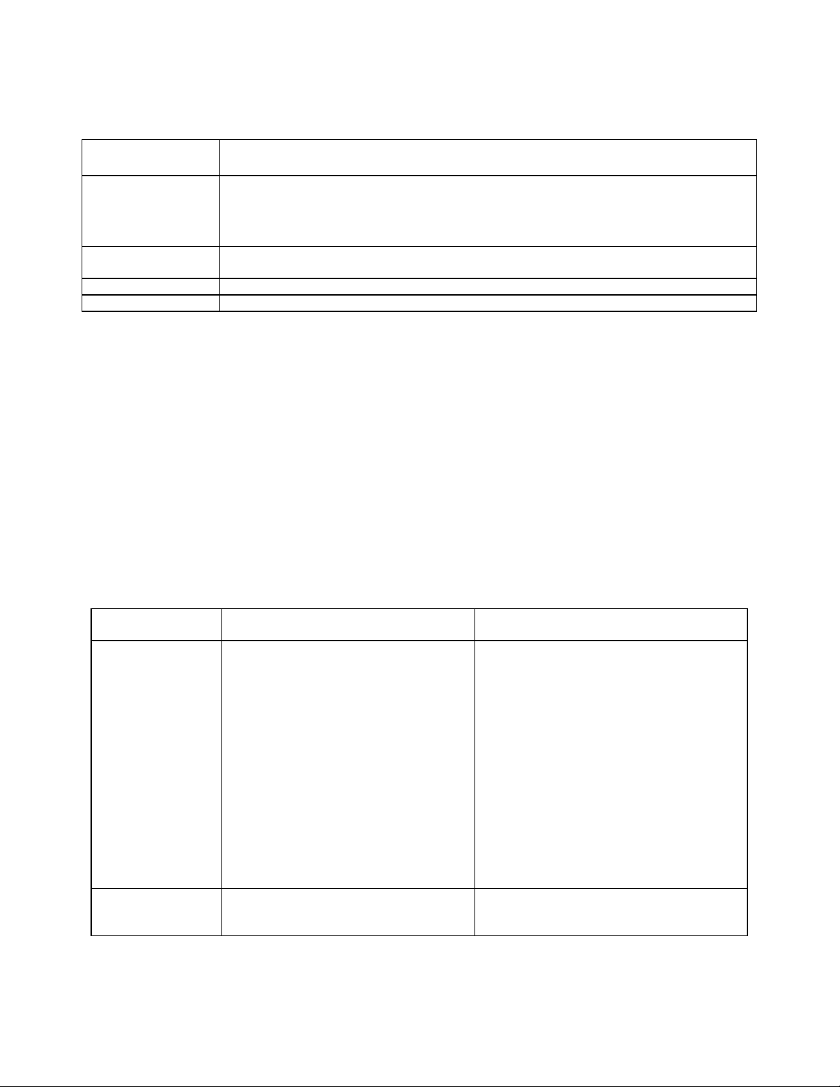
3. Calibration Description. TI parameters and performance specifications which
pertain to this calibration are listed in table 1.
Table 1. Calibration Description
Test instrument
parameters
Vertical deflection Range: 2 mV/div to 5 V/div in 11 steps (5 mV/div to 10 V/div for Tektronix, Type 475A)
Accuracy: ±3% with gain set at 5 mV/div
Time and linearity
A sweep or B
DLY’D sweep
A delaying sweep
(A intensified
sweep)
Range: Unmag: 0.5 s/div to 0.01 µs/div in 24 steps
Mag: 0.5 s/div to 1 ns/div in 24 steps
Accuracy: 5 ms/div to 0.01 µs/div
Unmag: ±1%
Mag: ±2% 0.5 s/div to 10 ms/div
Unmag: ±2%
Mag: ±3%
Range: 0.5 s/div to 0.05 µs/div in 22 steps
Accuracy: Unmag: ±2%
Mag: ±3%
Performance specifications
2
Page 3
TB 9-6625-2240-35
Table 1. Calibration Description - Continued
Test instrument
parameters
Delay time and
differential time
measurement
Risetime Range: 1.75 ns with aberrations not to exceed +4% or -4%, and total p-p of 4%
Bandwidth Dc to 200 MHz (Dc to 250 MHz for Tektronix, Type 475A)
Calibrator Range: 300 mV, ±l%
Range: 5 s to 0.05 µs after start of delaying A sweep
Accuracy: ±0.01 major dial divisions between dial settings of one major division or less
over entire range
(1.4 ns for Tektronix, Type 475A)
±1% between dial settings of more than 1 major dial division, increasing to
Performance specifications
±
0.5%
SECTION II
EQUIPMENT REQUIREMENTS
4. Equipment Required. Table 2 identifies the specific equipment to be used in this
calibration procedure. This equipment is issued with Secondary Transfer Calibration
Standards Set AN/GSM-286. Alternate items may be used by the calibrating activity.
The items selected must be verified to perform satisfactorily prior to use and must bear
evidence of current calibration. The equipment must meet or exceed the minimum use
specifications listed in table 2. The accuracies listed in table 2 provide a four-to-one
ratio between the standard and TI.
5. Accessories Required. The accessories required for this calibration are common
usage accessories, issued as indicated in paragraph 4 above, and are not listed in this
calibration procedure. The following peculiar accessory is also required for this
calibration: 5-80 pF standardizer.
Table 2. Minimum Specifications of Equipment Required
Common name
OSCILLOSCOPE
CALIBRATOR
DIGITAL
MULTIMETER
Minimum use specifications
Voltage output:
Range: 12 mV to 60 V
Frequency: 1 kHz
Accuracy: ±0.75%
Time markers:
Range: 1 ns to 0.5 s
Accuracy: ±.25%, .01 µs to 5 ms
±0.5%, 10 ms to 0.5 s
Risetime: 437.5 ps
Aberrations: ±1%
Level sine wave:
Reference frequency: 50 kHz
Amplitude: 30 mV
Capacity: >200 MHz
Voltage input:
Range: -15.23 to +113 V dc
Accuracy: ±.375%
John Fluke, Model 5820A, (5820A-5C-GHZ),
MIS-38938
John Fluke, Model 8840A/AF-05/09,
(AN/GSM-64D)
Manufacturer and model
(part number)
3
Page 4

TB 9-6625-2240-35
SECTION III
CALIBRATION PROCESS
6. Preliminary Instructions
a. The instructions outlined in paragraphs 6 and 7 are preparatory to the
calibration process. Personnel should become familiar with the entire bulletin before
beginning the calibration.
b. Items of equipment used in this procedure are referenced within the text by
common name as listed in table 2.
c. Unless otherwise specified, verify the result of each test and, whenever the test
requirement is not met, take corrective action before continuing with this calibration.
Adjustments required to calibrate the TI are included in this procedure. Additional
maintenance information is contained in the manufacturer's manual for this TI.
d. When indications specified in paragraphs 8 through 12 are not within tolerance,
perform the power supply check prior to making adjustments. After adjustments are
made, repeat paragraphs 8 through 12. Do not perform power supply check if all other
parameters are within tolerance.
e. Unless otherwise specified, all controls and control settings refer to the TI.
7. Equipment Setup
WARNING
HIGH VOLTAGE is used or exposed during the performance
of this calibration. DEATH ON CONTACT may result if
personnel fail to observe safety precautions. REDUCE
OUTPUT(S) to minimum after each step within the
performance check where applicable.
a. Remove TI protective cover as required for adjustment.
b. Position CH1 and CH2 controls as listed in (1) through (7) below:
(1) FOCUS, vertical POSITION, and SCALE ILLUM controls to midrange.
(2) VOLTS/DIV switches to 5 m (10 m for Tektronix, Type 475A) and VAR
controls fully cw (detent).
(3) VERT MODE CH1 pushbutton pressed (in).
(4) AC-GND-DC switches to GND.
(5) INTENSITY control fully ccw.
(6) INVERT pushbutton out.
4
Page 5

TB 9-6625-2240-35
(7) 20 MHz BW/TRIG VIEW pushbutton pressed in and released to full
bandwidth.
c. Position A and B triggering controls as listed in (1) through (7) below:
(1) A TRIGGER LEVEL control to 0 and SLOPE switch to + (positive).
(2) B (DLY'D) TRIGGER LEVEL control to 0 and SLOPE switch to + (positive).
(3) A TRIGGER SOURCE switch to NORM.
(4) B TRIGGER SOURCE switch to STARTS AFTER DELAY.
(5) A and B triggering COUPLING switches to AC.
(6) TRIG MODE AUTO pushbutton pressed (in).
(7) A TRIG HOLDOFF switch to NORM.
d. Position TI A and B sweep controls as listed in (1) through (5) below:
(1) A and B TIME/DIV switches to 1 ms and VAR control fully cw (detent).
(2) HORIZ DISPLAY A (A LOCKS KNOBS for all models SN B250000 and
above) pushbutton pressed (in).
(3) DELAY TIME dial to 0.00.
(4) X10 MAG pushbutton out.
(5) Horizontal POSITION (FINE) controls to midrange.
e. Connect TI to ac power source.
f. Pull POWER switch to ON and allow at least 20 minutes for warm -up.
g. Adjust INTENSITY, FOCUS, and ASTIG controls for suitable display.
8. Vertical Deflection
a. Performance Check
(1) Ensure CH1 VOLTS/DIV switch is set to 5 m (10 m for Tektronix, Type
475A).
(2) Adjust CH1 POSITION control to align trace on center horizontal graticule
line.
(3) Set CH1 VOLTS/DIV switch to 2 m (5 m for Tektronix, Type 475A). If trace
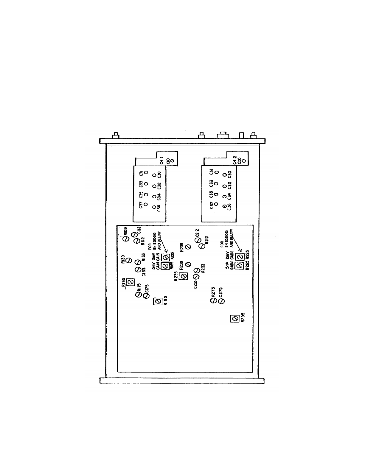
does not remain aligned with center horizontal graticule line, adjust R135 (fig. 1) to align
trace with center horizontal graticule line.
(4) Repeat (1) through (3) above for minimum trace shift when changing CH1
VOLTS/DIV switch from 5 m to 2 m (10 m to 5 m for Tektronix, Type 475A).
(5) Press VERT MODE CH2 pushbutton.
5
Page 6
TB 9-6625-2240-35
(6) Repeat technique of (1) thr ough (4) above using CH2 POSITION control and
adjusting R235 (fig. 1).
(7) Press VERT MODE CH1 pushbutton and set CH1 AC -GND-DC switch to
DC.
(8) Set CH1 VOLTS/DIV switch to 2 m (5 m for Tektronix, Type 475A) and
connect TI CH1 to oscilloscope calibrator CHAN 1.
(9) Press oscilloscope calibrator VOLTAGE pushbutton to illuminate green LED
and set frequency to 1 kHz.
6
Figure 1. Left side view.
Page 7
TB 9-6625-2240-35
(10) Perform steps a through c below:
(a) Use technique of (b) and (c) below for TI VOLTS/DIV switch settings and
oscilloscope calibrator VOLTAGE outputs listed in table 3.
(b) Rotate CH 1 POSITION knob to center trace on TI crt.
(c) Rotate oscilloscope calibrator knob located below EDIT FIELD
pushbutton to obtain 6 divisions of vertical display. Oscilloscope calibrator err display
will indicate within limits specified in table 3; if not, perform b below.
Table 3. Channel 1 Vertical Deflection Accuracy
1
Test instrument
VOLTS/DIV
Switch settings
2 m 12 mV 3
5
10 m 60 mV 3
20 m 120 mV 3
50 m .3 V 3
.1 V .6 V 3
.2 V 1.2 V 3
.5 V 3.0 V 3
1 V 6.0 V 3
2 V 12.0 V 3
5 V 30.0 V 3
10 V1 60.0 V 3
For Tektronix, Type 475A.
1
m 30 mV 3
Oscilloscope calibrator
Voltage output
Oscilloscope calibrator
Err display limits
(±%)
(11) Move TI connection from CH1 to CH2.
(12) Press VERT MODE CH2 pushbutton and set CH2 AC -GND-DC switch to
DC.
(13) Set CH2 VOLTS/DIV switch to 2 m (5 m for Tektronix, Type 475A).
(14) Press oscilloscope calibrator VOLTAGE pushbutton to illuminate green LED
and en sure frequency is set to 1 kHz.
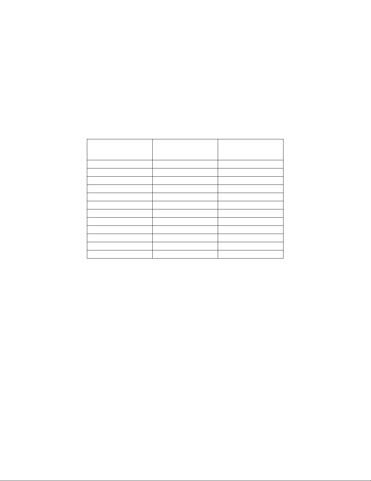
(15) Perform steps (a) through (c) below:
(a) Use technique of (b) and (c) below for TI VOLTS/DIV switch settings and
oscilloscope calibrator VOLTAGE outputs of those listed in table 4.
(b) Rotate TI CH 2 POSITION knob to center trace on crt.
(c) Rotate oscilloscope calibrator knob located below EDIT FIELD
pushbutton to obtain 6 divisions of vertical display. Oscilloscope calibrator err display
will indicate within limits specified in table 4.
7
Page 8
TB 9-6625-2240-35
Table 4. Channel 2 Vertical Deflection Accuracy
1
Test instrument
VOLTS/DIV
switch settings
2 m 12 mV
51 m 30 mV
10 m 60 mV
20 m 120 mV
50 m .3 V
.1 V .6 V
.2 V 1.2 V
.5 V 3.0 V
1 V 6.0 V
2 V 12.0 V
5 V 30.0 V
10 V1 60.0 V
For Tektronix, Type 475A.
Oscilloscope calibrator
Voltage output
Oscilloscope calibrator
Err display limits
± %
3
3
3
3
3
3
3
3
3
3
3
3
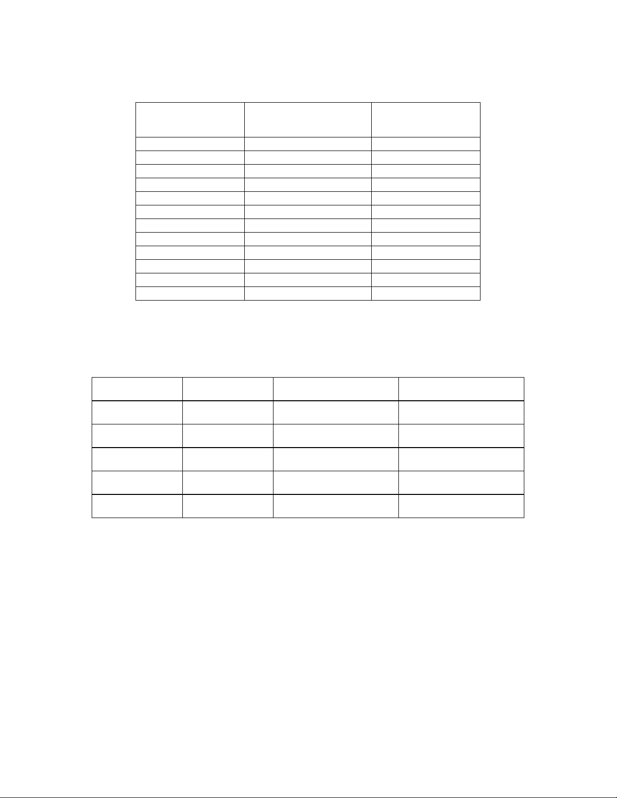
b. Adjustments. Set oscilloscope calibrator to required parameter listed in table 5
for particular TI you are calibrating. Perform appropriate adjustments listed in table 5
for 6 divisions of vertical display on TI.
Table 5. Adjustment Guide
Parameter
(mV gain)
2 475 Below B250000 CH 1 R125
2 475 B250000 and up CH 1 R195
5 475 All SN’s CH 1 R165
5 475A --- CH 1 R195
10 475A --- CH 1 R165
Tektronix
type
Serial number
Adjustments
(fig. 1) (R)
CH 2 R225
CH 2 R295
CH 2 R265
CH 2 R295
CH 2 R265
9. Main Sweep Timing
NOTE
For oscilloscopes with digital multimeters attached, refer to
calibration section of digital multimeter manual at this point.
a. Performance Check
(1) Press VERT MODE CH1 pushbutton and set VOLTS/DIV switch to .5 V.
(2) Perform steps (a) through (d) below:
(a) Press oscilloscope calibrator MARKER pushbutton to illuminate green
LED and ensure oscilloscope calibrator output is set to 1.000 ms.
(b) Connect oscilloscope calibrator CHAN 1 to TI CH1 through 50Ω
termination.
8
Page 9

TB 9-6625-2240-35
(c) Press oscilloscope calibrator OPR/STBY pushbutton for OPR indication
on oscilloscope calibrator display.
(d) Ensure TI TIME/DIV is set to 1 ms.
(3) Rotate POSITION knob to align 1st time marker to 1st verticule graticule line
on TI crt.
(4) Rotate oscilloscope calibrator knob located below EDIT FIELD pushbutton
for 1 time marker per division on crt. Oscilloscope calibrator err display will ind icate
within limits specified in table 6.
(5) Repeat technique of (3) and (4) above for TI settings and oscilloscope
calibrator MARKER outputs listed in table 6. Perform TI adjustments for each
TIME/DIV switch position listed in table 6 as needed.
Table 6. Timing Accuracy
Oscilloscope
calibrator
MARKER
output settings
1 ms 1 ms Out 1 b1
1 µs 10 µs In 2
10 µs 10 µs Out 1 C1064 (fig. 2)
1 µs 10 µs In 2
.1 µs .1 µs Out 1 C1009 (fig. 3)
10 ns .1 µs In 2
Test instrument
switch settings
TIME/DIV
Test instrument
X10 MAG
pushbutton
settings
Oscilloscope
calibrator err
display limits
(±%)
Adjustments
(R)
1Type 475 with SN B250000-up.
2Optional with SN B250000-up
Figure 2. Adjustment locations - top view.
9
Page 10

TB 9-6625-2240-35
+15 V
R1430
+50 V
-15 V
C1179
C1253
R1155
R1515
R950
R936
R938
+ 50 V
+110 V
TP
Figure 3. Adjustments locations - bottom view.
+5 V
-8 V
C1233
C1009
(6) Perform steps (a) through (d) below:
(a) Set TI A COUPLING switch to LF REJ.
(b) Set TI A SOURCE switch to CH1.
(c) Press TI X10 MAG pushbutton to on (in).
(d) Press TRIG MODE NORM pushbutton to (in).
NOTE
You may need to adjust A TRIGGER SLOPE LEVEL for a
stable display in step (8) below.
(7) Set oscilloscope calibrator output and TI to settings listed in table 7.
(8) Adjust horizontal POSITION control to align 1 marker per division. TI will
indicate as listed in table 7 .1 marker per division. Perform adjustments listed in table
7 if required.
Table 7. Delay Time and Differental Measurement
Test
instrument
VOLTS/DIV
switch
settings
.5 V .05 µs .05 µs 5 ns 2 b(2)
Test instrument
switch settings
TIME/DIV
A B
Oscilloscope
calibrator
MARKER
output
Test
instrument
indications
1 per division
± minor
divisions
Test
instrument
adjustments
(9) Set A SOURCE switch to NORM, and A COUPLING switch to AC.
(10) Press X10 MAG (IN) pushbutton to off (out).
10
Page 11

TB 9-6625-2240-35
(11) Use technique of (12) and (13) below for TI TIME/DIV switch settings and
oscilloscope calibrator MARKER settings listed in table 8. Perform adjustments as
needed listed in table 8.
(12) Adjust horizontal POSITION control to align 1st time marker with 1st
graticule line.
(13) Rotate oscilloscope calibrator knob located below EDIT FIELD pushbutton to
obtain 1 marker per division on TI. Oscilloscope calibrator err display will indicate
within limits specified in table 8.
b. Adjustments
(1) Set oscilloscope calibrator MARKER output to .1 ms. Press oscilloscope
calibrator OPR/STBY pushbutton for OPR indication on oscilloscope calibrator display
and adjust R1155 (fig. 3) for 1 marker per division (R).
NOTE
Interaction exists between C1233, C1253, and C1179 (fig. 3).
Adjust for best in-tolerance condition.
(2) Adjust C1233 and C1253 (fig. 3) in equal amounts until TI displays 1 marker
per division (R).
(3) Set oscilloscope calibrator MARKER output to 20 ns . Adjust C1179 (fig. 3)
for 1 marker per division (R).
Table 8. Sweep Timing Accuracy
Test instrument
TIME/DIV
switch settings
.02 µs .02 µs 1 b(3)
.01 µs 10 ns 1
.05 µs 50 ns 1
.2 µs .2 µs 1
.5 µs .5 µs 1
1 µs 1 µs 1
2 µs 2 µs 1
5 µs 5 µs 1
20 µs 20 µs 1
50 µs 50 µs 1
.1 ms .1 ms 1
.2 ms .2 ms 1
.5 ms .5 ms 1
1 ms 1 ms 1
2 ms 2 ms 1
5 ms 5 ms 1
Oscilloscope calibrator
output settings
MARKER
Oscilloscope
calibrator err
display limits
(±%)
Test instrument
adjustments
11
Page 12

TB 9-6625-2240-35
Table 8. Sweep Timing Accuracy - Continued
Test instrument
TIME/DIV
switch settings
10 ms 10 ms 2
20 ms 20 ms 2
50 ms 50 ms 2
.1 s .1 s 2
.2 s .2 s 2
.5 s .5 s 2
Oscilloscope calibrator
output settings
MARKER
Oscilloscope
calibrator err
display limits
(± %)
Test instrument
adjustments
10. Delay Time and Differential Time Measurement
a. Performance Check
(1) Position controls as listed in (a) through (g) below:
(a) HORIZ DISPLAY A INTEN pushbutton pressed (in).
(b) DELAY TIME POSITION dial to 1.00.
(c) Press TRIG MODE AUTO pushbutton to (in).
(d) Press X10 MAG (IN ) pushbutton to (in).
(e) Ensure oscilloscope calibrator CHAN 1 is connected to TI CH1 through
50Ω feedthrough termination.
(f) Set TI VOLTS/DIV, TIME/DIV switch settings and oscilloscope
calibrator MARKER output as listed in table 9.
(g) Adjust A TRIGGER SLOPE LEVEL as needed for a stable trace on crt.
NOTE
For Tektronix, Type 475, SN B250000, and above, and
Tektronix, Type 475A, perform (3) below then proceed to (4).
For all other models, proceed to (4) below.
(2) Adjust horizontal POSITION control to align 1st time marker with 1st
graticule line. Rotate oscilloscope calibrator knob located below EDIT FIELD output to
obtain 1 marker per division on TI. Oscilloscope calibrat or err display will be within
limits specified in table 9. Perform adjustments, if required, listed in table 9.
Table 9. Delay Time and Differental Measurement
Test instrument
VOLTS/DIV
switch settings
.5 1 µs 10 µs 1 µs 2 b(1)
Test instrument
switch settings
TIME/DIV
A B
Oscilloscope
calibrator
MARKER
output
Oscilloscope
calibrator err
display limits
(±%)
Test
instrument
adjustments
12
Page 13

TB 9-6625-2240-35
(3) Press HORIZ DISPLAY B DLY'D pushbutton (in).
(4) Press X10 MAG (IN) pushbutton to (out).
(5) Set TI VOLTS/DIV, TIME/DIV switch settings and oscilloscope calibrator
output as listed in table 10.
(6) Adjust horizontal POSITION control to align start of sweep with center
vertical graticule line. Leading edge of displayed time marker will be aligned with the
center vertical graticule line; if not, perform adjustment listed in table 10.
Table 10. Delay Time and Differental Measurement
Test
instrument
VOLTS/DIV
switch
settings
.5 10 µs 0.1 µs 10 µs b(2)
Test instrument
switch settings
TIME/DIV
A B
Oscilloscope
calibrator
MARKER output
settings
Test instrument
adjustment
(7) Set TI VOLTS/DIV, TIME/DIV switch and oscilloscope calibrator output as
listed in table 11.
(8) Rotate DELAY TIME POSITION dial to 9.00. Leading edge of displayed
time marker will be aligned with center vertical graticule line; if not, perform
adjustment listed in table 11.
Table 11. Delay Time and Differental Measurement
Test
instrument
VOLTS/DIV
switch
settings
.5 10 µs 0.1 µs 10 µs
Test instrument
switch settings
TIME/DIV
A B
Oscilloscope
calibrator
MARKER
output settings
Test instrument
DELAY TIME
POSITION
dial limits
(±)
.05
Test
instrument
adjustment
b(3)
(9) Rotate DELAY TIME POSITION dial to 1.00.
(10) Set TI VOLTS/DIV, TIME/DIV switch settings and oscilloscope calibrator
output as listed in table 12.
(11) Adjust horizontal POSITION control to align 1st marker with center vertical
graticule line using test instrument settings and oscilloscope calibrator MARKER
output setting listed in ta ble 12.
(12) Rotate DELAY TIME POSITION dial to align 9th time marker with center
vertical graticule line. DELAY TIME POSITION dial will indicate as listed in table 12.
If not, perform test instrument adjustments listed in table 12.
13
Page 14

TB 9-6625-2240-35
Table 12. Delay Time and Differental Measurement
Test
instrument
VOLTS/DIV
switch setting
.5 10 µs 10 µs 10 µs 8.95 9.05 b(4) through (7)
Test instrument
TIME/DIV
switch setting
A B
Oscilloscope
calibrator
MARKER
output setting
Test instrument
DELAY TIME
POSITION
dial limits
Min Max adjustments
Test instrument
NOTE
You may need to adjust A TRIGGER SLOPE LEVEL for a
stable display.
(13) Set TI VOLTS/DIV, TIME/DIV switch settings and oscilloscope calibrator
output as listed in table 13.
(14) Rotate DELAY TIME POSITION dial to 1.00.
(15) Set TI VOLTS/DIV, TIME/DIV switch settings and oscilloscope calibrator
output as listed in table 13.
(16) Adjust horizontal POSITION control to align 1st marker with center vertical
graticule line using test instrument settings and oscilloscope calibrator MARKER
output setting listed in table 13.
(17) Rotate DELAT TIME POSITION dial to align 9th time marker with center
vertical graticle line. DELAY TIME POSITION dial will indicate between 8.95 and
9.05; if not, perform adjustments listed in table 13.
(18) Rotate DELAY TIME POSITION knob to 0.0 .
Table 13. Delay Time and Differental Measurement
Test
instrument
VOLTS/DIV
switch settings
.5 0.1 µs 0.1 µs 0.1 µs 8.95 9.05 b(8) through (11)
Test instrument
switch settings
TIME/DIV
A B
Oscilloscope
calibrator
MARKER
output settin gs
Test instrument
DELAY TIME
POSITION
dial limits
Min Max
Test instrument
adjustments
b. Adjustments
(1) Adjust R950 (fig. 3) for 1 time marker per division (R).
(2) Adjust R938 (fig. 3) until start of sweep is aligned with the leading edge of the
displayed time marker (R).
NOTE
Interaction occurs between R936 and R938 (fig. 3). Readjust
as necessary for best in-tolerance condition.
(3) Adjust R936 (fig. 3) until start of sweep is aligned with the leading edge of the
displayed time marker (R).
14
Page 15

TB 9-6625-2240-35
(4) Set DELAY TIME POSITION dial to 1.00.
(5) Adjust C1023 (fig. 2) to align time marker with center vertical graticule line
(R).
(6) Set DELAY TIME POSITION dial to 9.00.
(7) Readjust C1023 (fig. 2) for best in-tolerance condition between DELAY TIME
POSITION dial readings of 1.00 and 9.00 to align time marker with center vertical
graticule line (R).
(8) Set DELAY TIME POSITION dial to 1.00.
(9) Adjust C1025 (fig. 2) to align time marker with center vertical graticule line
(R).
(10) Set DELAY TIME POSITION dial to 9.00.
(11) Readjust C1025 (fig. 2) for best in-tolerance condition between DELAY TIME
POSITION dial readings of 1.00 and 9.00 to align time marker with center vertical
graticule line (R).
11. Risetime and Bandwidth
a. Performance Check
(1) Press HORIZONTAL DISPLAY A (A LOCKS KNOBS for SN B250000 and
above) pushbutton (in). Connect oscilloscope calibrator CHAN 1 to TI CH1 through 10x
attenuator and 50Ω termination.
(2) Press and release 20 MHz BW/TRIG VIEW pushbutton to full bandwidth
and press VERT MODE CH1 pushbutton (in).
(3) Set TI VOLTS/DIV CH1 switch to 5m (10m for Tektronix, Type 475A).
(4) Use technique of step 5 below for TI settings and oscilloscope calibrator
output settings listed in table 14.
(5) Rotate oscilloscope calibrator knob below EDIT FIELD pushbutton to adjust
amplitude for 5 divisions of vertical deflection on TI. Square wave will have aberrations
not more than those listed in table 14; if not, perform adjustment as listed in table 14.
Table 14. High Frequency Compensation Adjustments
Oscilloscope calibrator
EDGE settings
Amplitude
200 mVpp 1 MHz 0.1
200 mVpp 100 kHz .5 µs 1 C471, C4773 (fig. 2) Top and corner
See footnotes at end of table.
Frequency
TIME/DIV
switch
settings
(µs)
0.05
Aberration limits
minor division or
minor division
pk-pk
(<)
1 C175, R175 (fig. 1)
Test instrument
CH1
adjustments
(R)
C133, R133 (fig. 1)
C112, R112 (fig. 1)
Portion of
waveform
affected
10 ns from
leading edge
2 ns from
leading edges
Front corner
15
Page 16

TB 9-6625-2240-35
Table 14. High Frequency Compensation Adjustments - Continued
Oscilloscope calibrator
EDGE settings
AMPLITUDE
FREQUENCY
TIME/DIV
switch
settings
(µs)
200 mVpp 10 kHz 20
10
5
1
1
Test instrument with SN B250000 and above.
2
Optional on some test instruments.
3
Affect both CH1 and CH2. Readjust as necessary.
Test instrument
Aberration limits
minor div ision or
minor division
pk-pk
(<)
1 R109 (fig. 1)
CH1
adjustments
(R)
R139 (fig. 1)
R475 (fig. 2)
R494 (fig. 2)3
1
2,3
Portion of
waveform
affected
Top and corner
(6) Remove TI connection from CH1 and connect to CH2 and press VERT
MODE CH2 pushbutton (in).
(7) Set TI VOLTS/DIV CH2 switch to 5m (10m for Tektronix, Type 475A).
(8) Use technique of step 9 below for TI settings and oscilloscope calibrator
output listed in table 15.
(9) Rotate oscilloscope calibrator knob below EDIT FIELD pushbutton to adjust
amplitude for 5 divisions of vertical deflection on TI. Square wave will have aberrations
not more than those listed in table 15, if not perform adjustment listed in table 15.
Table 15. High Frequency Compensation Adjustments
Oscilloscope calibrator
EDGE
settings
AMPLITUDE
FREQUENCY
TIME/DIV
switch settings
(µS)
200 mVpp 1 MHz 0.1
0.05
Abberation limits
minor division or
minor division pk-
pk
(<)
1 C275, R275 (fig. 1)
Test
instrument
CH2
adjustments
(R)
C233, R233 (fig. 1)
C212, R212 (fig. 1
Portion of
waveform
affected
10 ns from
leading edge
2 ns from
leading edges
Front corner
200 mVpp 100 kHz 0.5 1 C471, C4773 (fig. 2) Top and corner
200 mVpp 10 kHz 20
10
5
1
1
Test instrument with SN B250000 and above.
2
Optional on some test instruments.
3
Affect both CH1 and CH2. Readjust as necessary.
1 R209 (fig. 1)1
R239 (fig. 1)
R475 (fig. 2)
R494 (fig. 2)3
Top and corner
2,3
16
Page 17

TB 9-6625-2240-35
(10) Connect oscilloscope calibrator CHAN 1 to TI CH1 through 10x attenuator,
50Ω feedthrough termination, and 5 - 80 pF standardizer.
(11) Pull 20 MHz /TRIGVIEW pushbutton out to 20 MHz.
(12) Set TI TIME/DIV switch to .2 ms
(13) Oscilloscope calibrator output to 500 mV at 1 kHz.
(14) Set CH1 VOLTS/DIV switch to 5 m (10 m for Tektronix, Type 475A) and
press VERT MODE CH1 pushbutton (in).
(15) Rotate oscilloscope calibrator knob below EDIT FIELD pushbutton to adjust
amplitude for 5 divisions of vertical deflection on TI. Adjust standardizer for optimum
square wave presentation. If optimum square wave presentation cannot be obtained,
perform adjustments listed in table 16.
(16) Repeat technique of (15) above for remaining TI VOLTS/DIV switch settings
listed in table 16 (do not readjust standardizer). If optimum square wave presentation
cannot be obtained, perform adjustments listed in table 16.
Table 16. Voltage Compensation
Oscilloscope
calibrator
EDGE VOLTS/DIV Tektronix, Type 475 Tektronix, Type 475A
settings settings Square corner Flat top Square corner Flat top
500 mV pp 5 m --- C10 (CH1)1
1 V pp 10 m C36 C37 --- C10 (CH1)
1 V pp 20 m2 C34 C35 C36 C37
250 mV pp 50 m3 C32 C33 C34 C35
500 mV pp .1 --- --- C32 C33
1.25 V pp4 .5 C30 C31 --- ---
1.25 V pp
1
Adjust for optimum results between square corners and flat tops.
2
Remove termination from setup.
3
Attenuators from setup.
4
Maxium amplitude for oscilloscope calibrator. Make adjustments as best as possible.
5
Adjust A TRIGGER for stable display if required.
4,5
1 --- --- C30 C31
Test
instrument
Test instrument
CH1 and CH 2 adjustments
(fig. 1) (R)
--- ---
C50 (CH2)1
1
C50 (CH2)2
(17) Connect oscilloscope calibrat or CHAN 1 to TI CH2 through 10x attenuator,
50Ω feedthrough termination, and 5 - 80 pF standardizer.
(18) Set TI TIME/DIV switches to .2 ms.
(19) Set oscilloscope calibrator output to 500 mV at 1 kHz.
(20) Set CH2 VOLTS/DIV switch to 5 m (10 m for Tektronix, Type 475A) and
press VERT MODE CH2 pushbutton (in).
17
Page 18

TB 9-6625-2240-35
(21) Rotate oscilloscope calibrator knob below EDIT FIELD pushbutton to adjust
amplitude for 5 divisions of vertical deflection on TI. Adjust standardizer for optimum
square wave presentation. If optimum square wave presentation cannot be obtained,
perform adjustments listed in table 17.
(22) Repeat technique of (21) above for remaining TI VOLTS/DIV switch settings
listed in table 17 (do not readjust standardizer). If optimum square wave presentat ion
cannot be obtained, perform adjustments listed in table 17
Table 17. Voltage Compensation
Oscilloscope
calibrator
EDGE VOLTS/DIV Tektronix, Type 475 Tektronix, Type 475A
settings settings Square corner Flat top Square corner Flat top
500 mV pp 5 m --- C10 (CH1)1
1 V pp 10 m C36 C37 --- C10 (CH1)
1 V pp 20 m2 C34 C35 C36 C37
250 mV pp 50 m3 C32 C33 C34 C35
500 mV pp .1 --- --- C32 C33
1.25 V pp4 .5 C30 C31 --- ---
1.25 V pp
1
Adjust for optimum results between square corners and flat tops.
2
Remove termination from setup.
3
Attenuators from setup.
4
Maxium amplitude for oscilloscope calibrator. Make adjustments as best as possible.
5.
Adjust A TRIGGER for a stable display if required.
4,5
1 --- --- C30 C31
Test
instrument
Test instrument
CH1 and CH 2 adjustments
(fig. 1) (R)
--- ---
C50 (CH2)1
1
C50 (CH2)2
(23) Connect oscilloscope calibrator CHAN 1 to TI CH1 through 50Ω feedthrough
termination.
NOTE
Ensure 50Ω feedthrough termination, wattage, and
frequency ratings are adequate for test below.
(24) Position controls as listed in (a) through (d) below:
(a) TRIG MODE AUTO pushbutton pressed (in).
(b) X10 MAG pushbutton pressed to on (in).
(c) Press and release 20 MHz BW/TRIG VIEW pushbutton to full
bandwidth.
(d) VERT MO DE CH1 pushbutton pressed (in).
NOTE
Ensure oscilloscope calibrator FASTEDG and TDPULSE
are off when performing steps below.
18
Page 19

TB 9-6625-2240-35
(25) Perform steps (a) through (c) below:
(a) Ensure oscilloscope calibrator EDGE pushbutton green LED is
illuminated.
(b) Set TI VOLTS/DIV, TIME/DIV switch settings and oscilloscope
calibrator EDGE output to settings listed in table 18. Use technique of step (c) below for
TI switch settings and oscilloscope calibrator EDGE output settings listed in table 18.
(c) Rotate oscilloscope calibrator knob located below EDIT FIELD
pushbutton to adjust amplitude for 5 divisions on TI crt and measure risetime using
standard risetime technique. Risetime limits are listed in table 18.
Table 18. Channel 1 Risetime Measurement
Test instrument
switch settings
VOLTS/DIV TIME/DIV Amplitude Frequency (≤)
5 m 0.01 µs 25
10 m
(Tektronix,
Type 475A)
0.01 µs 25
Oscilloscope calibrator
output settings
mVpp
mVpp
EDGE
10 MHz 1.75 ns
10 MHz 1.4 ns
Test instrument
risetime
limits
(26) Move connection on TI to CH2 and press VERT MODE CH2 pushbutton (in).
NOTE
Ensure CH2 VOLTS/DIV AC CND DC switch is set to DC
for steps below.
(27) Set TI VOLTS/DIV, TIME/DIV settings and oscilloscope calibrator EDGE
output to settings listed in table 19. Use technique of step (28) below for TI switch
settings and oscilloscope calibrator EDGE output settings listed in table 19.
(28) Rotate oscilloscope calibrator knob located below EDIT FIELD pushbutton to
adjust amplitude for 5 divisions on TI crt and measure risetime using standard risetime
technique. Risetime limits are listed in table 19.
Table 19. Channel 2 Risetime Measurement
Test instrument
switch settings
VOLTS/DIV TIME/DIV Amplitude Frequency (≤)
5 m 0.01 µs 25 mV pp 10 MHz 1.75 ns
10 m
(Tektronix,
Type 475A)
0.01 µs 25 mV pp 10 MHz 1.4 ns
Oscilloscope calibrator
EDGE
output settings
Test instrument
risetime
limits
19
Page 20

TB 9-6625-2240-35
(29) Press VERT MODE CH1 pushbutton (in), and set X10 MAG pushbutton
(out).
(30) Connect CH1 through 50Ω feedthrough termination to oscilloscope calibrator
CHAN 1.
(31) Press oscilloscope calibrator LEVEL SINE pushbutton to illuminate green
LED.
(32) Set TI VOLTS/DIV, TIME/DIV settings and oscilloscope calibrator LEVEL
SINE output to settings listed in table 20.
(33) Rotate oscilloscope calibrator knob below EDIT FIELD pushbutton to adjust
amplitude for 6 divisions of verticle deflection on TI.
Table 20. Bandwidth Measurement Setup
Test instrument
switch settings
VOLTS/DIV TIME/DIV Amplitude Frequency (≥)
5 m 0.1 ms 30 mV pp 50 kHz
10 m
(Tektronix,
Type 475A)
0.1 ms 60 mV pp 50 kHz
Oscilloscope calibrator
LEVEL SINE
output settings
to
200 MHz
to
250 MHz
Test instrument
amplitude limits
(divisions)
4.2
4.2
NOTE
To perform the step below, press EDIT FIELD pushbutton
as required to place underline under one of the frequency
digits.
(34) Rotate oscilloscope calibrator knob below EDIT FIELD pushbutton to sweep
oscilloscope from 50 KHz to 200 MHZ while observing displayed waveform amplitude
on TI crt. Displayed waveform will be 4.2 divisions or greater in amplitude throughout
entire range to 200 MHz (250 MHz for Tektronix, Type 475A).
b. Adjustments. No further adjustments.
12. Calibrator
a. Performance Check
(1) Connect TI CALIBRATOR (front panel) to TI CH1.
(2) Press VERT MODE CH1 pushbutton (in).
(3) Press oscilloscope calibrator VOLTAGE pushbutton to illuminate green LED.
(4) Set TIME/DIV to .2 ms and CH1 VOLTS/DIV switch to 50 m. Adjust CH1
VOLTS/DIV VAR control for 6 divisions of vertical deflection on TI.
20
Page 21

TB 9-6625-2240-35
(5) Remove connection at TI CALIBRATOR and connect to oscilloscope
calibrator CHAN 1.
21
Page 22

TB 9-6625-2240-35
(6) Set TI switch settings and oscilloscope calibrator output as listed in table 21.
(7) Rotate oscilloscope calibrator knob below EDIT FIELD pushbutton to adjust
for 6 divisions of vertical deflection on TI. Oscilloscope calibrator err display will
indicate as specified in table 21, if not perform b below.
Table 21. TI Calibrator Output Check
Test instrument
switch settings
VOLTS/DIV TIME/DIV Amplitude Frequency (±%)
50 m .2 ms 300 mV pp 1 kHz 1
Oscilloscope calibrator
VOLTAGE
output settings
Test instrument
Err
display limits
b. Adjustments
(1) Set oscilloscope calibrator DEVIATION switch to OFF.
(2) Adjust TI VOLTS/DIV controls for 6 divisions of vertical deflection on TI.
(3) Disconnect oscilloscope calibrator from TI and connect TI CALIBRATOR
(front panel) and (ground) (front panel) to TI CH1 input.
(4) Adjust R1515 (fig. 3) for 6 divisions of vertical deflection on TI (R).
13. Power Supply
NOTE
Do not perform power supply checks if all other parameters
are within tolerance.
a. Performance Check
(1) Connect digital multimeter to TI test point +50 V (fig. 3) and chassis ground.
Digital multimeter will indicate as listed in table 22 below; if not, perform b below.
(2) Repeat technique of (1) above for TI test points and voltage indications listed
in table 22. Digital multimeter will indicate within limits specified in table 22.
Table 22. Power Supply Voltage
Test instrument
test points
(fig. 3) Min Max
+50 V +49.75 +50.25
+110 V +107 +113
+15 V +14.77 +15.23
+5 V +4.92 +5.08
-15 V -14.77 -15.23
-8 V -7.88 -8.12
Digital mu ltimeter indications
(V dc)
b.
+50
Adjustments
V (R).
. Adjust R1430 +50 V (fig. 3) for digital multimeter indication of
22
Page 23

TB 9-6625-2240-35
14. Final Procedure
a. Deenergize and disconnect all equipment and reinstall protective cover on TI.
b. Annotate and affix DA label/form in accordance with TB 750-25.
23
Page 24

By Order of the Secretary of the Army:
TB 9-6625-2240-35
0120708
Distribution:
To be distributed in accordance with IDN 344233, requirements for calibration procedure TB 9-66252240-35.
PIN: 045981-000
 Loading...