

Page 1
4500-CILK-* Interlock Cable
Keithley Instruments, Inc.
28775 Aurora Road
Cleveland, Ohio 44139
(440) 248-0400
www.keithley.com
User’s Guide
Introduction
This document contains information on the 4500-CILK-* interlock cable. This cable is used to connect the 451x-QIVC
card interlock circuits to a test fixture switch to inhibit source outputs when the test fixture lid is open.
Connection precautions
WARNING The interlock is required for safe operation. The test fixtures must ensure that the
interlock circuit is disabled (source outputs inhibited) so that an operator is not
exposed to any harmful conditions.
Description
Cable configuration
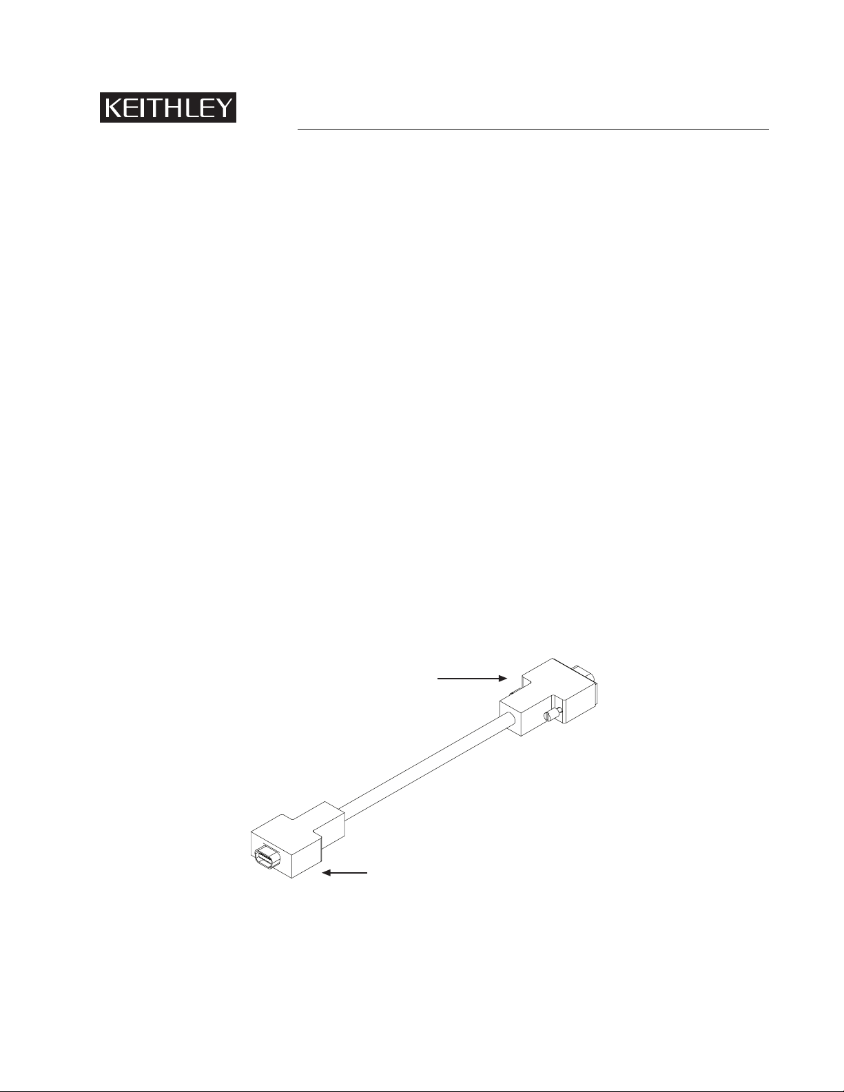
The overall configuration of the 4500-CILK-* interlock cable is shown in Figure 1. The cable includes a 14-pin male connector that mates with the 451x-QIVC card interlock connector on one end, and a 9-pin D-sub female connector on the
other end for connections to a test fixture.
Figure 1
4500-CILK-* cable configuration
9-Pin connector
to test fixture
14-Pin connector to
451x-QIVC card
interlock connector
PA-872 Rev. B / 12-03
Page 2
Cable lengths
As summarized in Table 1, the 4500-CILK-* interlock cable is available in four different lengths. The 2m length
cable (4500-CILK-2) is supplied with the 451x-QIVC card.
Table 1
4500-CILK-* cable lengths
Model Length (meters)
4500-CILK-0.5 0.5
4500-CILK-1 1
4500-CILK-2* 2
4500-CILK-3 3
* Cable supplied with 451x-QIVC card
Connections
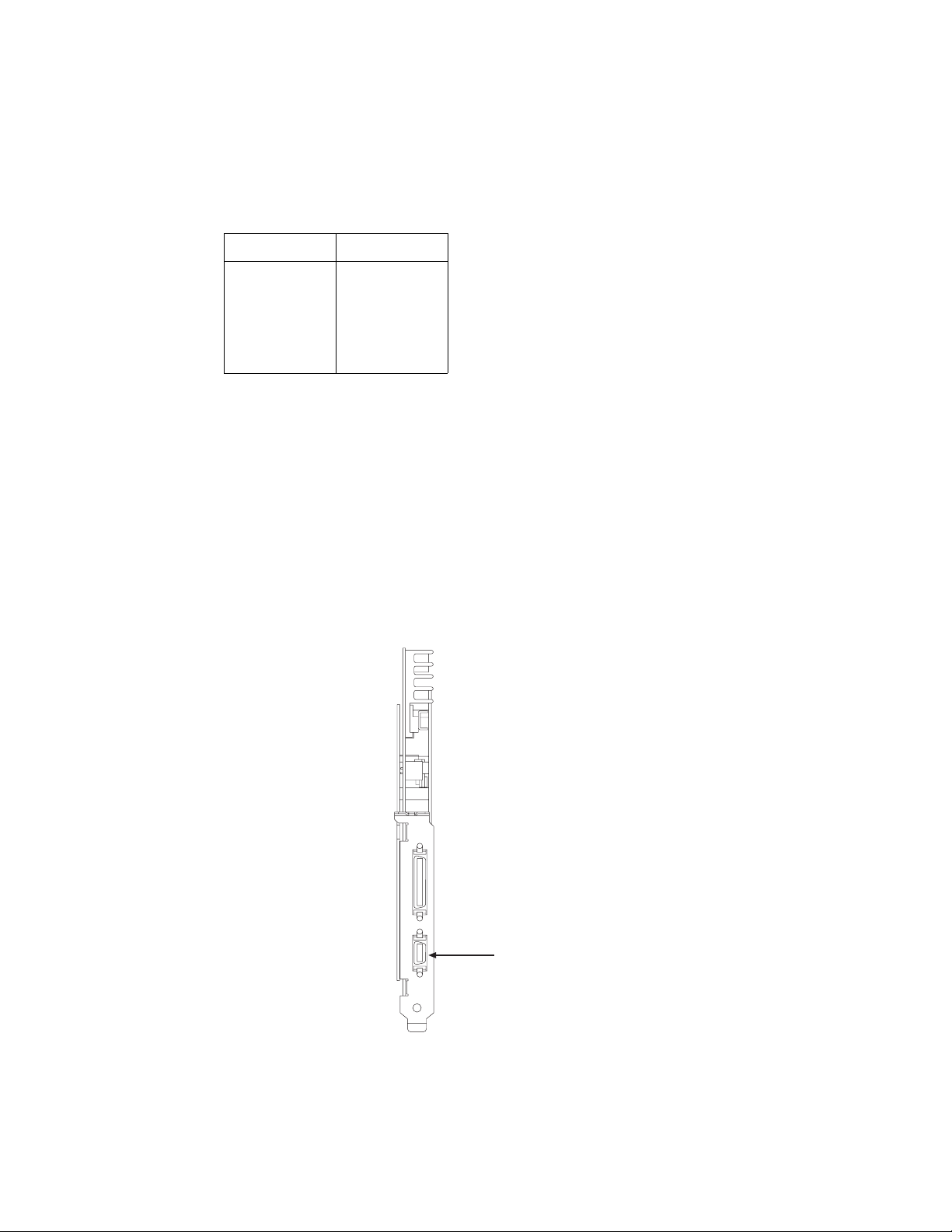
Card connections
To connect the interlock cable, connect the 14-pin male cable connector to the interlock connector on the 451x-QIVC
card (Figure 2).
Figure 2
451x-QIVC card interlock connector
Interlock
connector
2
Page 3

Interlock connections
Connector terminal designations
Table 2 lists card connector terminal designations for the 14-pin and 9-pin connectors.
Table 2
Interlock cable terminal designations
14-Pin
cable
connector
1 1 +5VD (+5V digital supply)
2 6 DIAG – RX (not implemented)
3 2 DIAG – TX (not implemented)
4 7 Interlock Channel A Enable
5 3 Interlock Channel B Enable
6 8 Interlock Channel C Enable
7 4 Interlock Channel D Enable
8 9 D – GND (digital ground)
9 – 14 N.C. - - -
9-Pin
cable
connector
Signal description
Typical interlock connections
Figure 3 shows typical connections between the 451x-QIVC card interlock connector and an interlock switch in a test
fixture using a 4500-CILK-* cable. In this instance, a single interlock switch is connected to the enable lines of all
four channels. Other applications that require the output of each channel to be individually controlled will require a
separate switch for each channel. In either case, outputs will be enabled (turned on) when the switch is closed. When
the switch is open, output(s) will be turned off and cannot be turned on.
CAUTION Do not short the +5V signal to ground. Doing so will result in system damage.
The interlock is not designed to protect the DUT during an interlock event. In
the interest of protecting the operator, the output relays of the interlock circuit
close immediately and before the output is driven to a low voltage potential. As
a result, the DUT will see the energy in the DUT cable. This energy may display
as a significant negative (opposite polarity of the source current) voltage at the
DUT. Activating the interlock may damage the DUT.
NOTE The +5V line on the interlock connector (pin 1) is internally protected with a 0.75A fuse.
Inadvertently shorting this line to chassis ground will trip the fuse, disabling the interlock control circuits, and outputs cannot be turned on. The fuse will automatically reset
a few minutes after the overload condition is removed.
3
Page 4

Figure 3
Interlock connections
4510-QIVC or 4511-QIVC Card
+5V
Pin 1
Card
interlock
connector
terminals
4500-CILK-*
cable 9-pin
connector
terminals
Pin 1
Channel A Enable
Channel B Enable
Channel C Enable
Channel D Enable
Pin 4
Pin 5
Pin 6
Pin 7
4500-CILK-*
interlock
cable
Pin 7
Pin 3
Pin 8
Pin 4
Switch
Test
fixture
Channel outputs are enabled
when switch is closed, disabled
when switch is open.
4
 Loading...