


Model 4200-SCS
Startup Guide
Start Here! It’s easy... Step 1 Unpack your Keithley 4200-SCS
Step 2 System connections – Power cord, keyboard, and printer (optional)
Step 3 Connect DUT test fixture to 4200-SCS
Step 4 Power-up & log-in
Step 5 Start KITE, open the “default” project, and select the “vds-id” test
Step 6 Test definition
Step 7 Run “vds-id” test
Step 8 View data sheet
Step 9 View graph
Step 10 Printing and exporting data
This Startup Guide selects the “default” project and runs the “vds-id” test. If you wish to select a different
project and/or test, you must modify the procedures accordingly. Figure 1 shows how the KITE window
will look after the “default” project and “vds-id” test is selected.
Figure 1: KITE interface (“default” project shown with “vds-id” test selected)
Project Navigator Selected Test Toolbar KITE Workspace
Message Area
PA-716 Rev. C / 11-03 1
Model 4200-SCS
Keithley
4200-SCS
Mouse/Keyboard
Connector
Parallel
Connector
Keyboard
Shielded
Parallel
Cable
Parallel
Printer
* v1.1 USB connector (Windows
XP Professional operating
system) – If using a USB printer,
connect it to the USB port.
USB
Port*
INSTRUMENT
CONNECTIONS
SMU ONLY
SMU AND GNDU
GNDU
COM 1
INSTRUMENTS
SLOT8SLOT7SLOT6SLOT5SLOT4SLOT3SLOT2SLOT
1
LPT 1
INSTALLATION
CATEGORY
I
S
E
N
S
E
F
O
R
C
E
C
O
M
M
O
N
SENSE LO
GUARD
SENSE LO
COMMON
COMMON
FORCE
SENSE
GUARD
4200
SMU
SENSE LO
SENSE
FORCE
PA CNTRL
KEITHLEY
4200
SMU
SENSE LO
SENSE
FORCE
PA CNTRL
KEITHLEY
4210
SMU
SENSE LO
SENSE
FORCE
PA CNTRL
KEITHLEY
4210
SMU
SENSE LO
SENSE
FORCE
PA CNTRL
KEITHLEY
4200
TM
INTLK
IN
OUT
KEITHLEY
Y-Cable (supplied)
Power Cord
(supplied)
Step 1 Unpack your Keithley 4200-SCS
What’s in the box:
• 4200-SCS System – SMUs are built-in, and PreAmps are installed on the rear panel of the mainframe. A
PreAmp adds five lower current source-measure ranges to an SMU (10nA, 1nA, 100pA, 10pA, and 1pA).
The PreAmps can be removed from the rear panel and mounted remotely on a tester.
• Cables – 2 for each SMU.
• Y-Cable – Use to connect keyboard (with pointing device) to mainframe.
• Power cord
• 4200-SCS KTE Interactive CD-ROM
• 4200-SCS Complete Reference CD-ROM
How to lift:
• Lift the 4200-SCS from the bottom.
• Do not lift from the front bezel.
• Set on a bench or install in a rack with the optional slide rack mounting kit.
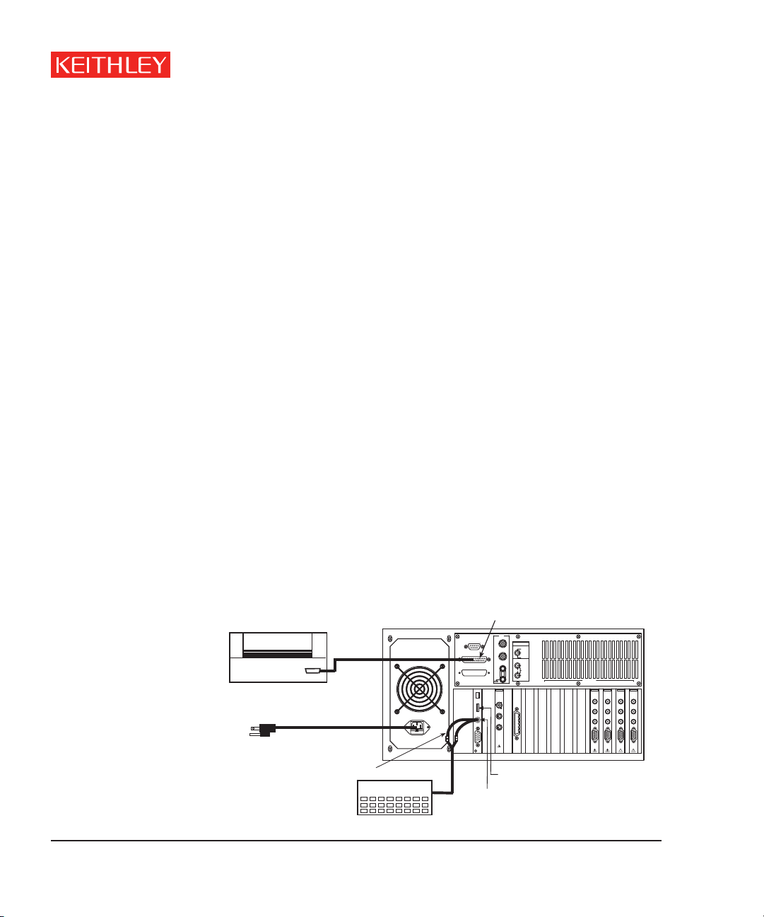
Step 2 System connections – Power cord, keyboard, and printer (optional)
Basic system connections to the 4200-SCS (shown in Figure 2) include the keyboard (which has a built-in
pointing device), the supplied power cord, and an optional printer. If using a USB printer, connect it to the
USB port.
Figure 2: System connections
2
WARNING Plug the female end of the supplied power cord into the
4200-SCS, but DO NOT connect the male end to line power at
this time. Steps 2 and 3 of this Startup Guide must be performed
with the line power disconnected.

Step 3 Connect DUT test fixture to 4200-SCS
INSTRUMENT
CONNECTIONS
SMU ONLY
SMU AND GNDU
GNDU
INSTRUMENTS
SLOT
8
SLOT
7
SLOT
6
SLOT
5
SLOT
4
SLOT
3
SLOT
2
SLOT
1
S
E
N
S
E
F
O
R
C
E
C
O
M
M
O
N
SENSE LO
GU
SENSE LO
COMMON
COMMON
FORCE
SENSE
GU
SENSE LO
SENSE
FORCE
SENSE LO
SENSE
FORCE
SENSE LO
SENSE
FORCE
SENSE LO
SENSE
FORCE
PA CN
PA-1 REMOT
PA-1 REMOT
PA-1 REMO
P
RE
MP
4200-PA-1 REMO
CONTR
OL
OUT
IN
INSTR
UMEN
T
CONNECTIONS
SMU ONL
Y
SMU AND GNDU
GNDU
INSTR
UMENTS
SLO
T
8
SLO
T
7
SLO
T
6
SLO
T
5
SLO
T
4
SLO
T
3
SLO
T
2
SLO
T
1
S
E
N
S
E
F
O
R
C
E
C
O
M
M
O
N
SENSE LO
GU
SENSE LO
COMMON
COMMON
FORCE
SENSE
GU
SENSE LO
SENSE
FORCE
SENSE LO
SENSE
FORCE
PA CNTRL
SENSE LO
SENSE
FORCE
PA CNTRL
SENSE LO
SENSE
FORCE
PA CNTRL
OUT
IN
PA CNTRL
Four
Terminal
Device
Four
Terminal
Device
“FORCE”
Connectors
“FORCE”
Connectors
on SMUs
PreAmps
“FORCE” Connector
on GNDU
“FORCE” Connector on GNDU
Test Fixture
Test Fixture
Connections to SMUs
Connections to SMUs/PreAmps
Figure 3 shows how to connect a test fixture for a 4-terminal device to the 4200-SCS. The test fixture must
be equipped with standard 3-lug female triax connectors.
• Connections to SMUs – To connect directly to an SMU, use a Mini triax cable that is terminated with a
miniature male triax connector on one end and a standard 3-slot male triax connector on the other end.
• Connections to PreAmps – To connect to a PreAmp, use a cable that is terminated with a standard
3-slot male triax connector on both ends.
NOTE Connections are snug; push firmly.
Figure 3: DUT test fixture connections to 4200-SCS
Startup Guide
Step 4 Power-up & log-in
A. Make sure the power switch is in the O (out) position. The POWER switch is located on the front panel
in lower right-hand corner.
B. Plug the male end of the line cord into a properly grounded AC line power receptacle.
C. Turn on the 4200-SCS by pushing in the POWER switch to the I (in) position.
D. When prompted, simultaneously press Ctrl - Alt - Del.
E. At the KIUSER prompt, press ENTER. There is no password for this account.
CAUTION When first starting a KTE-Interactive software tool, you must
answer “Yes” to an on-screen license agreement. Answering
“No” makes your system nonfunctional until you reinstall the
software.
3

Model 4200-SCS
Step 5 Start KITE, open the “default” project, and select the “vds-id” test
A. Start KITE by double-clicking the following KITE icon on the Windows desktop:
Double-click to start KITE.
B. When KITE starts, the “default” project will open automatically if it has been set as the default project. If a
different project opens, perform the three steps in Figure 4 to open the “default” project. The Project
Navigator for the “default” project is shown in Figure 1.
NOTE If the Project Navigator is not displayed when KITE is started, click the
View menu and select the Project Navigator item. The View menu is
located at the upper left-hand side of the KITE window.
Figure 4: Open “default” project
1. From the File menu,
click Open Project.
* When browsing, use the following directory path to locate the “default.kpr” project file:
C:\S4200\kiuser\Projects\default\default.kpr
4
2. Use the browser to select
the default project*.
3. Click Open to open
the “default” project.

C. Select the “vds-id” test and display the test Definition tab as shown in Figure 5. The Definition
tab for the “vds-id” test is shown in Figure 6.
Figure 5: “default” Project Navigator – selecting the “vds-id” test
Double-click “vds-id” to select the test
and display the test Definition tab.
The checkbox for “vds-id” must be
checked in order to run the test. If
unchecked, click the checkbox to
insert a ✔.
Startup Guide
Step 6 Test definition
The test is defined from the test Definition tab shown in Figure 6. As shown in the tab, the device is
connected to three SMUs and the Ground Unit (GNDU). In general, SMU3 is used as a voltage step function
to provide four different gate voltages (2V, 3V, 4V, and 5V). SMU2 is used to perform a 51 point sweep of
drain voltage (0V to 5V) at each gate voltage. A current measurement is performed at each voltage
sweep point.
A. If desired, the setup for SMUs and the GNDU can be changed. A settings window is displayed by clicking
the appropriate FORCE MEASURE bar as shown in Figure 6. Figure 7 shows the settings window for SMU3. The settings windows for the other SMUs and GNDU are similar.
5

Model 4200-SCS
Figure 6: “vds-id” Definition tab - How to display a setup window for SMUs and GNDU
Click to set
up SMU2.
Click to set
up SMU3.
Click to set
up SMU1.
Figure 7: Setup for SMU3
These parameters set
the gate voltage steps:
2V, 3V, 4V, and 5V.
If you make any
changes to the SMU3
setup, click OK to
enter the changes and
close the window.
Click to set
up SMU3.
B. After making any changes to the test definition, click Save All on the toolbar to save the settings:
Click Save All to
save settings.
6

Step 7 Run “vds-id” test
A. In the Project Navigator (see Figure 5), make sure the “vds-id” test is highlighted and the checkbox is
checked.
B. On the toolbar, click the green Run Test button to run the test one time:
Click Run Test
to start test.
While the test is running, the Run Test button turns gray and the Abort Test button turns red. Also the
MEASURING indicator (located on lower right-hand corner of the front panel) will be on while the test is
running. When the test if finished, the Run Test button turns green.
Troubleshooting hints:
• A selected test will not run if the Run Test button is not green. Here are a few reasons why the
Run Test button will not be green:
- A test is still running.
- The checkbox for the test is not checked (see Figure 5).
- Changes to the test setup were not saved (see Step 6B).
Startup Guide
• If a selected test still will not run, click the Status tab for the test. This tab provides status information
for the test.
7

Model 4200-SCS
Step 8 View data sheet
The data sheet for the “vds-id” test is displayed by clicking the Sheet tab for the test. Use the tabs at the
bottom of the Sheet to display the data type. A sample data sheet for the “vds-id” test is shown in Figure 8.
Figure 8: Sample data sheet for “vds-id” test
Click to export
data (see Step 10).
Click to display
Data sheet*.
Click to display
Calc sheet*.
Click to display
Settings sheet*.
* To select more than one sheet for selective printing, hold down the Ctrl key and then click the tab. See
Step 10 to print Sheet data.
8

Step 9 View graph
The graph for the “vds-id” test is displayed by clicking the Graph tab for the test. A sample graph for the
“vsd-id” test is shown in Figure 9. As shown, there are four I-V curves – one for each gate voltage. The
graph was customized to include the Legend box and use different colors for the graph series. The Graph
Settings menu (shown in Figure 10) was used to select the Legend box and change series colors.
Figure 9: Sample graph for “vds-id” test
Startup Guide
9

Model 4200-SCS
Figure 10: Graph settings menu
Graph Settings
To display the Graph
Settings menu: Right-click
mouse anywhere in the
graph area.
OR
From the Tools menu,
select Graph Settings.
Click to select (
Legend box.
Click Graph Properties and
then Series to change the
properties for each of the
four series.
✔)
10

Step 10 Printing and exporting data
Printing Sheet data
A. In the KITE workspace, click the Sheet tab to display test data. You can selectively print the Data
sheet, Calc sheet, and/or the Settings sheet. Figure 8 shows how to select sheets for printing.
B. From the FILE menu (at the upper left-hand side of the KITE window), select the Print option.
C. In the Print setup window, there are two print options. You can print the Selected Sheet(s)
(Data, Calc, and/or Sheet) or the Entire Workbook (Data, Calc, and Sheet).
D. In the Print setup window, click OK to print the data.
Printing the Graph
A. In the KITE workspace, click the Graph tab to display the graph.
B. From the FILE menu (at the upper left-hand side of the KITE window), select the Print option.
C. In the Print setup window, click OK to print the graph.
Exporting data into MS Excel-compatible Worksheet
Startup Guide
A. In the KITE workspace, click the Sheet tab to display the test data.
B. In the Sheet tab, click the Save As button as shown in Figure 8.
C. From the Save As setup window, specify a file name and path and click Save. The default directory
path for exporting data is C:\S4200\kiuser\export.
11

Keithley Instruments, Inc. 28775 Aurora Road • Cleveland, Ohio 44139 • 440-248-0400 • Fax: 440-248-6168
1-888-KEITHLEY (534-8453) www.keithley.com
© Copyright 2003 Keithley Instruments, Inc. PA-716
Printed in the U.S.A. Rev. C / 11-03
 Loading...