

Page 1

Keithley Instruments
28775 Aurora Road
Cleveland, Ohio 44139
1-800-833-9200
tek.com/keithley
Model 4200-CVU-PWR Parts Package
PA-977 Rev. E August 2021 *PPA-977E* 1
#
Description
Part number
Quantity
1
Remote bias tee
4205-RBT
2 2 SMA male to BNC female adapter
CS-1252
2 3 SMA male to BNC male adapter
CS-1479
2 4 SMA tee female-male-female
CS-1391
2 5 50 Ω SMA male shorting cap
011019500
1
6
SMA plug to SMA plug coaxial
cable
CA-406B
2 7 SMA male to SSMC Y cable
assembly
CA-426
2
Instruction sheet
Introduction
The Model 4200-CVU-PWR CVU Power Package enables C-V measurements with a dc voltage bias of up to
±200 V or 400 V differential (0 V to ±400 V) and a current output of up to 300 mA. Note that the items shipped
may vary from those pictured here.
Figure 1: 4200-CVU-PWR package
Page 2

Model 4200-CVU-PWR Parts Package
2 PA-977 Rev. E August 2021
Using this package, the 4215-CVU Capacitance-Voltage Unit measures the capacitance and either one or two
4200-SMUs or 4215-SMUs are used to supply the dc bias or sweep voltage. The 4200-CVU-PWR is
compatible with the 4200A-SCS and 4200-SCS.
Connect to a device
The voltage output determines if one or two 4205-RBTs are required in the test circuit. For C-V measurements
with an applied voltage bias up to ±200 V, one 4205-RBT is required. For C-V measurements with a voltage
differential up to 400 V, two 4205-RBTs are required.
To make C-V measurements with an applied voltage bias up to +/- 200 V, connect one SMU (source-measure
unit), one 4215-CVU (capacitance-voltage unit), and one 4205-RBT to the device, as shown in the next figure.
The SMU sources the dc voltage and the CVU measures the capacitance of the device under test (DUT). The
4205-RBT allows coupling of the ac signals from the CVU and the dc signal from the SMU.
Page 3

Model 4200-CVU-PWR Parts Package
PA-977 Rev. E August 2021 3
In this setup, you can connect either the CVL1 (LPOT and LCUR) or CVH1 (HPOT and HCUR) to the ac Input
of the 4205-RBT. By default, the acc ammeter is connected to the CVL1.
To make C-V measurements with a voltage differential up to 400 V, two 4205-RBTs and two 4200-SMUs or
4210-SMUs are required, in addition to the 4215-CVU (see next figure). In this configuration, you connect SMU
1 and the CVL1 (LPOT and LCUR) terminals of the 4215-CVU through one 4205-RBT to one side of the
device. Connect the other side of the device through a second 4205-RBT, to both SMU 2 and the CVH1 (HPOT
and HCUR) terminals of the 4215-CVU. This setup allows 400 V differential measurements, for example, 0 to
400 V, –100 to 300 V, or –400 V to 0 V.
Control high voltage measurements using software
The hivcvulib user library contains two modules, SweepV and CvsT, that allow you to make high voltage
C-V measurements. If one 4205-RBT is used, the SweepV module allows you to sweep a dc voltage across the
DUT using the SMU and measure the capacitance using the 4215-CVU. If two 4205-RBTs are used with the
SweepV module, one SMU is used to sweep the dc voltage and the other SMU is used to apply an offset dc
bias, as shown in the previous figure.
The CvsT module provides capacitance measurements as a function of time at a user-specified dc bias. You
can also use this module with either one or two 4205-RBTs. With one 4205-RBT and one SMU, capacitance
measurements can be made with up to 200 V dc bias. With two 4205-RBTs and two SMUs, capacitance
measurements can be made up to 400 V dc bias.
You can open the SweepV and CvsT modules in a project using a user test module (UTM). These modules are
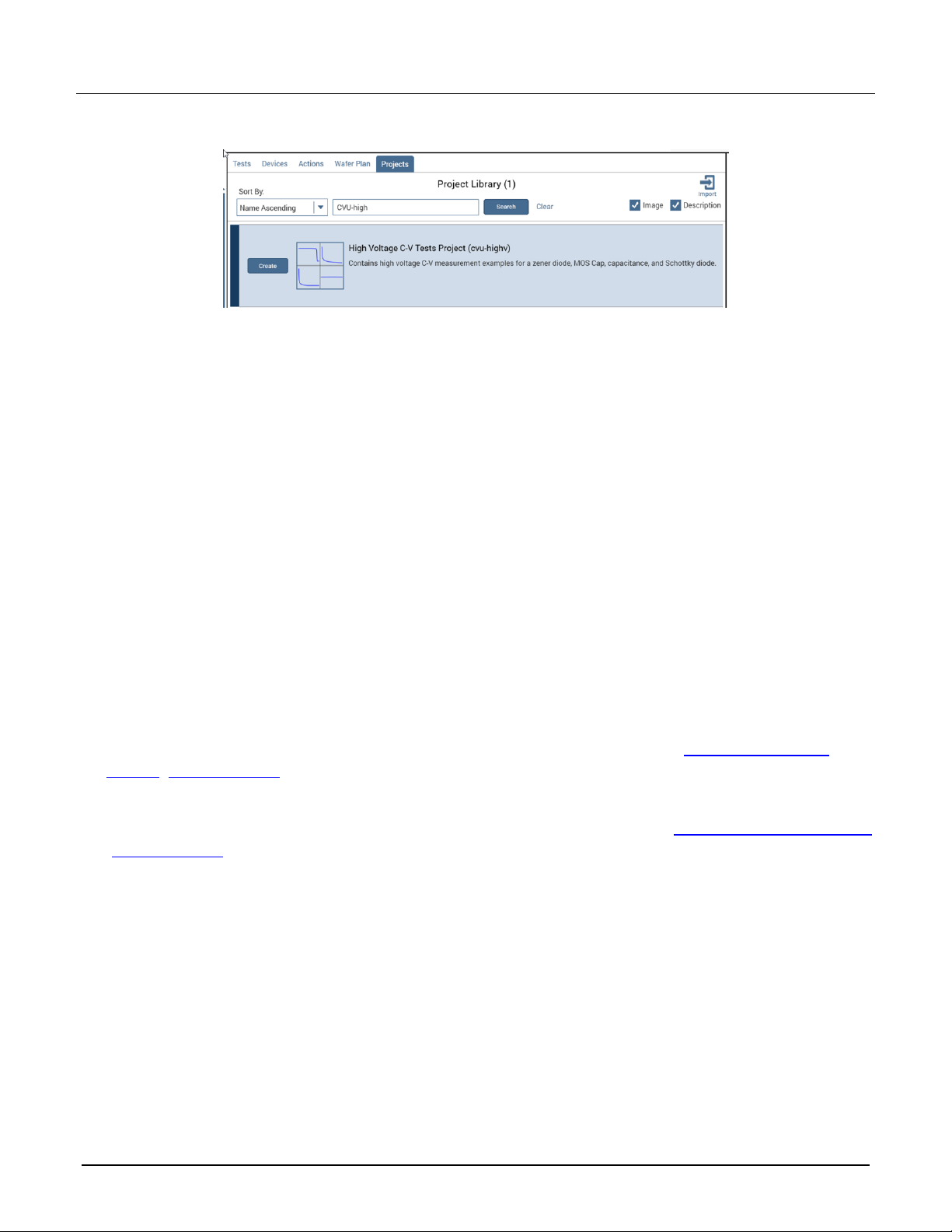
also preconfigured in a project. On the 4200A-SCS, the project is the High Voltage C-V Tests Project
(cvu-highv). On the 4200-SCS, the project is CVU_highV.
Page 4
Model 4200-CVU-PWR Parts Package
4 PA-977 Rev. E August 2021
If you are using a 4200A-SCS, to locate the project, you can search Projects in Clarius:
If you are using a 4200-SCS, to locate the project, you can find it at the following location:
C:\S4200\kiuser\Projects\_CV
These projects use both the SweepV and CvsT modules to make measurements on devices.
On the 4200A-SCS, you can create user modules by selecting Custom Test from the Test Library.
To create a user module:
1. Choose Select.
2. In the Test Library, select Custom Test, Choose a test from the pre-programmed library (UTM).
3. Drag the test to the project tree.
4. Select Configure.
5. In the Test Settings pane, under User Libraries, select hivcvulib.
6. In the User Modules list, select CvsT or SweepV.
More detail about the 4200-CVU-PWR
For more information about using the 4200-CVU-PWR with a 4200A-SCS, go to the Keithley Instruments
website (tek.com/keithley) and search for the document named Using the 4200-CVU-PWR C-V Power Package
to Make High Voltage and High Current C-V Measurements with the Model 4200A-SCS Parameter Analyzer.
For more information about using the 4200-CVU-PWR with a 4200-SCS, go to the Keithley Instruments website
(tek.com/keithley) and search for the document Using the Model 4200-CVU-PWR C-V Power Package to Make
High Voltage and High Current C-V Measurements with the Model 4200-SCS Semiconductor Characterization
System.
Page 5

PA-977 Rev. E August 2021 5
Safety precautions
The following safety precautions should be observed before using this product and any associated instrumentation. Although
some instruments and accessories would normally be used with nonhazardous voltages, there are situations where hazardous
conditions may be present.
This product is intended for use by personnel who recognize shock hazards and are familiar with the safety precautions required
to avoid possible injury. Read and follow all installation, operation, and maintenance information carefully before using the
product. Refer to the user documentation for complete product specifications.
If the product is used in a manner not specified, the protection provided by the product warranty may be impaired.
The types of product users are:
Responsible body is the individual or group responsible for the use and maintenance of equipment, for ensuring that the
equipment is operated within its specifications and operating limits, and for ensuring that operators are adequately trained.
Operators use the product for its intended function. They must be trained in electrical safety procedures and proper use of the
instrument. They must be protected from electric shock and contact with hazardous live circuits.
Maintenance personnel perform routine procedures on the product to keep it operating properly, for example, setting the line
voltage or replacing consumable materials. Maintenance procedures are described in the user documentation. The procedures
explicitly state if the operator may perform them. Otherwise, they should be performed only by service personnel.
Service personnel are trained to work on live circuits, perform safe installations, and repair products. Only properly trained
service personnel may perform installation and service procedures.
Keithley products are designed for use with electrical signals that are measurement, control, and data I/O connections, with low
transient overvoltages, and must not be directly connected to mains voltage or to voltage sources with high transient
overvoltages. Measurement Category II (as referenced in IEC 60664) connections require protection for high transient
overvoltages often associated with local AC mains connections. Certain Keithley measuring instruments may be connected to
mains. These instruments will be marked as category II or higher.
Unless explicitly allowed in the specifications, operating manual, and instrument labels, do not connect any instrument to mains.
Exercise extreme caution when a shock hazard is present. Lethal voltage may be present on cable connector jacks or test
fixtures. The American National Standards Institute (ANSI) states that a shock hazard exists when voltage levels greater than
30 V RMS, 42.4 V peak, or 60 VDC are present. A good safety practice is to expect that hazardous voltage is present in any
unknown circuit before measuring.
Operators of this product must be protected from electric shock at all times. The responsible body must ensure that operators
are prevented access and/or insulated from every connection point. In some cases, connections must be exposed to potential
human contact. Product operators in these circumstances must be trained to protect themselves from the risk of electric shock. If
the circuit is capable of operating at or above 1000 V, no conductive part of the circuit may be exposed.
For maximum safety, do not touch the product, test cables, or any other instruments while power is applied to the circuit under
test. ALWAYS remove power from the entire test system and discharge any capacitors before: connecting or disconnecting
cables or jumpers, installing or removing switching cards, or making internal changes, such as installing or removing jumpers.
Do not touch any object that could provide a current path to the common side of the circuit under test or power line (earth)
ground. Always make measurements with dry hands while standing on a dry, insulated surface capable of withstanding the
voltage being measured.
For safety, instruments and accessories must be used in accordance with the operating instructions. If the instruments or
accessories are used in a manner not specified in the operating instructions, the protection provided by the equipment may be
impaired.
Do not exceed the maximum signal levels of the instruments and accessories. Maximum signal levels are defined in the
specifications and operating information and shown on the instrument panels, test fixture panels, and switching cards.
Chassis connections must only be used as shield connections for measuring circuits, NOT as protective earth (safety ground)
connections.
The WARNING heading in the user documentation explains hazards that might result in personal injury or death. Always read
the associated information very carefully before performing the indicated procedure.
Page 6

6 PA-977 Rev. E August 2021
The CAUTION heading in the user documentation explains hazards that could damage the instrument. Such damage may
invalidate the warranty.
The CAUTION heading with the symbol in the user documentation explains hazards that could result in moderate or minor
injury or damage the instrument. Always read the associated information very carefully before performing the indicated
procedure. Damage to the instrument may invalidate the warranty.
Instrumentation and accessories shall not be connected to humans.
Before performing any maintenance, disconnect the line cord and all test cables.
To maintain protection from electric shock and fire, replacement components in mains circuits — including the power
transformer, test leads, and input jacks — must be purchased from Keithley. Standard fuses with applicable national safety
approvals may be used if the rating and type are the same. The detachable mains power cord provided with the instrument may
only be replaced with a similarly rated power cord. Other components that are not safety-related may be purchased from other
suppliers as long as they are equivalent to the original component (note that selected parts should be purchased only through
Keithley to maintain accuracy and functionality of the product). If you are unsure about the applicability of a replacement
component, call a Keithley office for information.
Unless otherwise noted in product-specific literature, Keithley instruments are designed to operate indoors only, in the following
environment: Altitude at or below 2,000 m (6,562 ft); temperature 0 °C to 50 °C (32 °F to 122 °F); and pollution degree 1 or 2.
To clean an instrument, use a cloth dampened with deionized water or mild, water-based cleaner. Clean the exterior of the
instrument only. Do not apply cleaner directly to the instrument or allow liquids to enter or spill on the instrument. Products that
consist of a circuit board with no case or chassis (e.g., a data acquisition board for installation into a computer) should never
require cleaning if handled according to instructions. If the board becomes contaminated and operation is affected, the board
should be returned to the factory for proper cleaning/servicing.
Safety precaution revision as of June 2017.
 Loading...