


Model 4200A-SCS
Clarius
User’s Manual
4200A-914-01 Rev. D March 2023
tek.com/keithley
*P4200A-914-01D*
4200A-914-01D

Clarius
Model 4200A-SCS
User's Manual

© 2023, Keithley Instruments
Cleveland, Ohio, U.S.A.
All rights reserved.
Any unauthorized reproduction, photocopy, or use of the information herein, in whole or in part,
without the prior written approval of Keithley Instruments is strictly prohibited.
All Keithley Instruments product names are trademarks or registered trademarks of Keithley
Instruments, LLC. Other brand names are trademarks or registered trademarks of their
respective holders.
Actuate
®
Copyright © 1993-2003 Actuate Corporation.
All Rights Reserved.
Microsoft, Visual C++, Excel, and Windows are either registered trademarks or trademarks of
Microsoft Corporation in the United States and/or other countries.
Document number: 4200A-914-01 Rev. D March 2023

Safety precaut ions
The following safety precautio ns should be observed before using this product and any associated instrumentation. Although
some instruments and accessories would normally be used with nonhazardous voltages, there are situations where hazardous
conditions may be present.
This product is intended for use by personnel who recogn ize sho ck haz ards and are familiar with the safety precautions required
to avoid possible injury. Read and follow all installation, operation, and maintenance information carefully before using the
product. Refer to the user documentation for complete product specifications.
If the product is used in a manner not specified, the protection provided by the product warranty may be impaired.
The types of product users are:
Responsible body is the individual or group responsible for the use and maintenance of equipment, for ensuring that the
equipment is operated within its specifications and operating limits, and for ensuring that operators are adequately trained.
Operators use the product for its intended function. They must be trained in electrical safety procedures and proper use of the
instrument. They must be protected from electric shock and contact with hazardous live circuits.
Maintenance personnel perform routine procedures on the product to keep it operating properly, for example, setting the line
voltage or replacing consumable materials. Maintenance procedures are described in the user documentation. The procedures
explicitly state if the operator may perform them. Otherwise, they should be performed only by service personnel.
Service personnel are trained to work on live circuits, perform safe installations, and repair products. Only properly trained
service personnel may perform installation and service procedures.
Keithley products are designed for use with electrical signals that are measurement, control, and data I/O connections, with low
transient overvoltages, and must not be directly connected to mains voltage or to voltage sources with high transient
overvoltages. Measurement Category II (as referenced in IEC 60664) connections require protection for high transient
overvoltages often associated with local AC mains connections. Certain Keithley measuring instruments may be connected to
mains. These instruments will be marked as category II or higher.
Unless explicitly allowed in the specifications, operating manual, and instrument labels, do not connect any instrument to mains.
Exercise extreme caution when a shock hazard is present. Lethal voltage may be present on cable connector jacks or test
fixtures. The American National Standards Institute (ANSI) states that a shock hazard exists when voltage levels greater than
30 V RMS, 42.4 V peak, or 60 VDC are present. A good safety practice is to expect that hazardous voltage is present in any
unknown circuit before measuring.
Operators of this product must be protected from electric shock at all times. The responsible body must ensure that operators
are prevented access and/or insulated from every connection point. In some cases, connections must be exposed to potential
human contact. Product operators in these circumstances must be trained to protect themselves from the risk of electric shock. If
the circuit is capable of operating at or above 1000 V, no conductive part of the circuit may be exposed.
Do not connect switching cards directly to unlimited power circuits. They are intended to be used with impedance-limited
sources. NEVER connect switching cards directly to AC mains. When connecting sources to switching cards, install protective
devices to limit fault current and voltage to the card.
Before operating an instrument, ensure that the line cord is connected to a properly-grounded power receptacle. Inspect the
connecting cables, test leads, and jumpers for possible wear, cracks, or breaks before each use.
When installing equipment where access to the main power cord is restricted, such as rack mounting, a separate main input
power disconnect device must be provided in close proximity to the equipment and within easy reach of the operator.
For maximum safety, do not touch the product, test cables, or any other instruments while power is applied to the circuit under
test. ALWAYS remove power from the entire test system and discharge any capacitors before connecting or disconnecting
cables or jumpers, installing or removing switching cards, or making internal changes, such as installing or removing jumpers.
Do not touch any object that could provide a current path to the common side of the circuit under test or power line (earth)
ground. Always make measurements with dry hands while standing on a dry, insulated surface capable of withstanding the
voltage being measured.

For safety, instruments and accessories must be used in accordance with the operating instructions. If the instruments or
accessories are used in a manner not specified in the operating instructions, the protection provided by the equipment may be
impaired.
Do not exceed the maximum signal levels of the instruments and accessories. Maximum signal levels are defined in the
specifications and operating information and shown on the instrument panels, test fixture panels, and switching cards.
When fuses are used in a product, replace with the same type and rating for continued protection against fire hazard.
Chassis connections must only be used as shield connections for measuring circuits, NOT as protective earth (safety ground)
connections.
If you are using a test fixture, keep the lid closed while power is applied to the device under test. Safe operation requires the use
of a lid interlock.
screw is present, connect it to protective earth (safety ground) using the wire recommended in the user documentation.
If a
The
symbol on an instrument means caution, risk of hazard. The user must refer to the operating instructions located in the
user documentation in all cases where the symbol is mark ed on the instr u ment .
The
symbol on an instrument means warning, risk of electric shock. Use standard safety precautions to avoid personal
contact with these voltages.
The symbol on an instrument shows that the surface may be hot. Avoid personal contact to prevent burns.
The symbol indicates a connection terminal to the equipment frame.
If this symbol is on a product, it indicates that mercury is present in the display lamp. Please note that the lamp must be
properly disposed of according to federal, state, and local laws.
The WARNING heading in the user documentation explains hazards that might result in personal injury or death. Always read
the associated information very carefully before performing the indicated procedure.
The CAUTION heading in the user documentation explains h azard s that coul d dama ge the instrument. Such damage may
invalidate the warranty.
The CAUTION heading with the
sy mbol in the user documentation explains hazards that could result in moderate or minor
injury or damage the instrument. Always read the associated information very carefully before performing the indicated
procedure. Damage to the instrument may invalidate the warranty.
Instrumentation and accessories shall not be connected to humans.
Before performing any maintenance, disconnect the line cord and all test cables.
To maintain protection from electric shock and fire, replacement components in mains circuits — including the power
transformer, test leads, and input jacks — must be purchased from Keithley. Standard fuses with applicable national safety
approvals may be used if the rating and type are the same. The detachable mains power cord provided with the instrument may
only be replaced with a similarly rated power cord. Other components that are not safety-related may be purc ha sed from o ther
suppliers as long as they are equivalent to the original component (note that selected parts should be purchased only through
Keithley to maintain accuracy and functionality of the product). If you are unsure about the applicability of a replacement
component, call a Keithley office for information.
Unless otherwise noted in product-specific literature, Keithley instruments are designed to operate indoors only, in the following
environment: Altitude at or below 2,000 m (6,562 ft); temperature 0 °C to 50 °C (32 °F to 122 °F); and pollution degree 1 or 2.
To clean an instrument, use a cloth dampened with deionized water or mild, water-based cleaner. Clean the exterior of the
instrument only. Do not apply cleaner directly to the instrument or allow liquids to enter or spill on the instrument. Products that
consist of a circuit board with no case or chassis (e.g., a data acquisition board for installation into a computer) should never
require cleaning if handled according to instructions. If the board becomes contaminated and operation is affected, the board
should be returned to the factory for proper cleaning/servicing.
Safety precaution revision as of June 2018.

Table of contents
Introduction .............................................................................................................. 1-1
Get started with Clarius ........................................................................................................ 1-1
Clarius interface ................................................................................................................... 1-2
Touchscreen basics .................................................................................................................. 1-3
Choose the project phase ......................................................................................................... 1-3
Run tests and set up your workspace ....................................................................................... 1-4
Organize items in the project tree ............................................................................................. 1-5
Select items from the libraries ................................................................................................... 1-6
Configure the project ................................................................................................................. 1-7
Analyze data ............................................................................................................................. 1-8
Messages .................................................................................................................................. 1-9
Help pane .................................................................................................................................. 1-9
Additional Clarius+ applications ........................................................................................... 1-9
Embedded computer policy ............................................................................................... 1-10
Projects and tests .................................................................................................... 2-1
Introduction .......................................................................................................................... 2-1
Set up a simple project......................................................................................................... 2-1
Select project components ........................................................................................................ 2-1
Add a device and test to the project .......................................................................................... 2-2
Rearrange items in the project tree ........................................................................................... 2-3
Delete objects in the project tree ............................................................................................... 2-4
Configure a simple test ........................................................................................................ 2-4
Set the key parameters ............................................................................................................. 2-6
Run a simple test ................................................................................................................. 2-7
Working with the Projects dialog .......................................................................................... 2-8
Open a project ........................................................................................................................... 2-8
Edit project information ............................................................................................................. 2-9
Create a new project from the Projects dialog......................................................................... 2-10
Export a project ....................................................................................................................... 2-10
Import a project ....................................................................................................................... 2-10
Copy or cut a project ............................................................................................................... 2-12
Show Directories ..................................................................................................................... 2-12
Delete a project ....................................................................................................................... 2-13
View Projects .......................................................................................................................... 2-13
Migrate projects from 4200-SCS systems ............................................................................... 2-14
Manage projects for multiple users ......................................................................................... 2-14
Set up a complex project.................................................................................................... 2-15
Customize tests ....................................................................................................................... 2-15
Link tests or actions ................................................................................................................ 2-18
Add actions ............................................................................................................................. 2-19
Example: Creating a project ............................................................................................... 2-20
Equipment required ................................................................................................................. 2-20
Device connections ................................................................................................................. 2-21
Set up the measurements in Clarius ....................................................................................... 2-22
Configure a complex test ................................................................................................... 2-29
Test and terminal settings ....................................................................................................... 2-29
Step or sweep multiple device terminals in the same test ....................................................... 2-30

Table of contents
Manual
Model 4200A-SCS Clarius User's
Configure actions .................................................................................................................... 2-32
Run a complex test ............................................................................................................ 2-32
Run devices and tests ............................................................................................................. 2-32
Monitor a test ..................................................................................................................... 2-36
Enable the Monitor option ....................................................................................................... 2-36
Running a test using Monitor................................................................................................... 2-37
Demo Project overview ...................................................................................................... 2-38
4-terminal n-MOSFET tests..................................................................................................... 2-39
3-terminal NPN BJT tests ........................................................................................................ 2-39
Resistor tests .......................................................................................................................... 2-40
Diode tests .............................................................................................................................. 2-40
Capacitor tests ........................................................................................................................ 2-40
Analyze data ............................................................................................................. 3-1
Introduction .......................................................................................................................... 3-1
Spreadsheet ......................................................................................................................... 3-2
Options on the Run worksheet .................................................................................................. 3-2
Run Settings .............................................................................................................................. 3-3
Run sheet .................................................................................................................................. 3-4
Formulas List of the Run worksheet .......................................................................................... 3-6
Terminal Settings pane (Analyze) ............................................................................................. 3-6
Module Settings pane (Analyze) ............................................................................................... 3-6
Measurement status .................................................................................................................. 3-7
Run History ........................................................................................................................ 3-10
Change the name of a test run ................................................................................................ 3-11
Delete test runs from Ru n History ........................................................................................... 3-12
Working with the Run History pane ......................................................................................... 3-13
Searching for a test run ........................................................................................................... 3-13
Add notes to a test run ............................................................................................................ 3-13
Copy the settings of a test run to the Configure screen .......................................................... 3-13
Setting the Run History size .................................................................................................... 3-14
Analyze test data for projects ............................................................................................. 3-14
Select data for the project-level Analyze pane ........................................................................ 3-15
Remove data from the project-level Analyze pane .................................................................. 3-16
Graph the data for test runs ............................................................................................... 3-16
Open a graph .......................................................................................................................... 3-16
Options on the graph ............................................................................................................... 3-17
View detail on a data point ...................................................................................................... 3-18
Customize the graph ............................................................................................................... 3-18
Save results and graphs .................................................................................................... 3-31
Customizing Clarius ................................................................................................ 4-1
Customize Clarius ................................................................................................................ 4-1
Add objects to the library...................................................................................................... 4-1
Add a test to the library ............................................................................................................. 4-2
Add a device to the Device Library ............................................................................................ 4-2
Add an action to the library........................................................................................................ 4-3
Add a project to the library ........................................................................................................ 4-3
Edit a library object you added .................................................................................................. 4-3
Edit an object in the library ........................................................................................................ 4-4
Project tree display options .................................................................................................. 4-6

Model 4200A
of contents
-SCS Clarius User's Manual Table
Messages display option ...................................................................................................... 4-6
My Settings .......................................................................................................................... 4-6
Specify environment settings .................................................................................................... 4-6
Specify run settings ................................................................................................................... 4-8
Set graph defaults ................................................................................................................... 4-10
Custom GPIB Abort Options ................................................................................................... 4-10
Logging ................................................................................................................................... 4-11
Tools................................................................................................................................... 4-11
Instrum ent Tools ..................................................................................................................... 4-12
Data Export tool ...................................................................................................................... 4-29
Defining the UTM user interface ............................................................................. 5-1
Define the user interface for a user test module (UTM) ....................................................... 5-1
Allow access to the UTM UI editor ....................................................................................... 5-2
Open the UTM UI Editor....................................................................................................... 5-3
Organize parameters into groups ........................................................................................ 5-4
Add a group............................................................................................................................... 5-5
Modify a group .......................................................................................................................... 5-7
Remove a group ........................................................................................................................ 5-7
Define an image for the user interface ................................................................................. 5-7
Edit the attributes for a test parameter ................................................................................. 5-8
Control types ........................................................................................................................... 5-10
Add parameters to a UTM for stepping configuration .............................................................. 5-28
Add verify rules for a UTM....................................................................................................... 5-29
Example of using the editor ............................................................................................... 5-30
UTM UI definition file information ....................................................................................... 5-32
Reset defaults .................................................................................................................... 5-32
Copy or move UTM UI definitions ...................................................................................... 5-32
Formulator ................................................................................................................ 6-1
Introduction .......................................................................................................................... 6-1
Open the Formulator ............................................................................................................ 6-2
Configure Formulator calculations ....................................................................................... 6-3
Formulator dialog ................................................................................................................. 6-3
Formula area ............................................................................................................................. 6-3
Data Series ............................................................................................................................... 6-3
Number pad .............................................................................................................................. 6-4
Functions................................................................................................................................... 6-4
Constants .................................................................................................................................. 6-4
Apply Set to ............................................................................................................................... 6-5
Using the Formulator options ............................................................................................... 6-5
Real-time functions, operators, and formulas ...................................................................... 6-6
Post-test-only functions and formulas .................................................................................. 6-6
Editing Formulator formulas and constants ......................................................................... 6-7

Table of contents
User's Manual
Model 4200A-SCS Clarius
Deleting Formulator formulas and constants ....................................................................... 6-8
Identify data analysis requirements ..................................................................................... 6-8
Determining the type of calculation: an example ....................................................................... 6-8
Determining range data for a calculation: an example .............................................................. 6-8
Creating an analysis formula ................................................................................................... 6-10
Adding an analysis formula to the test .................................................................................... 6-10
Executing an analysis formula ................................................................................................. 6-11
Viewing analysis results in the Analyze she et ......................................................................... 6-11
Viewing analysis results in the Analyze graph ......................................................................... 6-11
Formulator function reference ............................................................................................ 6-12
ABS Formulator function ......................................................................................................... 6-12
DELTA Formulator function ..................................................................................................... 6-13
EXP Formulator function ......................................................................................................... 6-13
LOG Formulator function ......................................................................................................... 6-14
LN Formulator function ............................................................................................................ 6-14
SQRT Formulator function ...................................................................................................... 6-15
Statistics ............................................................................................................................. 6-15
AVG Formulator function ......................................................................................................... 6-15
MAVG Formulator function ...................................................................................................... 6-16
MAX Formulator function ........................................................................................................ 6-16
MEDIAN Formulator function .................................................................................................. 6-17
MIN Formulator function .......................................................................................................... 6-17
STDEV Formulator function .................................................................................................... 6-17
Trigonometry ...................................................................................................................... 6-18
ACOS Formulator function ...................................................................................................... 6-18
ASIN Formulator function ........................................................................................................ 6-18
ATAN Formulator fu nction ....................................................................................................... 6-19
COS Formulator function ........................................................................................................ 6-19
DEG Formulator function ........................................................................................................ 6-20
RAD Formulator function ......................................................................................................... 6-20
SIN Formulator function .......................................................................................................... 6-21
TAN Formulator function ......................................................................................................... 6-21
Array ................................................................................................................................... 6-22
AT Formulator function ............................................................................................................ 6-22
DIFF Formulator function ........................................................................................................ 6-22
FINDD Formulator function ..................................................................................................... 6-23
FINDLIN Formulator function .................................................................................................. 6-23
FINDU Formulator function ..................................................................................................... 6-24
FIRSTPOS Formulator function .............................................................................................. 6-24
INTEG Formulator function ..................................................................................................... 6-25
INDEX Formulator function ..................................................................................................... 6-26
LASTPOS Formulator function ................................................................................................ 6-27
MAXPOS Formulator function ................................................................................................. 6-27
MINPOS Formulator function .................................................................................................. 6-27
SUBARRAY Formulator function ............................................................................................. 6-28
SUMMV Formulator function ................................................................................................... 6-28
Line fits ............................................................................................................................... 6-29
EXPFIT Formulator function .................................................................................................... 6-29
EXPFITA Formulator function ................................................................................................. 6-30
EXPFITB Formulator function ................................................................................................. 6-30
LINFIT Formulator function ..................................................................................................... 6-31
LINFITSLP Formulator function ............................................................................................... 6-32
LINFITXINT Formulator function ............................................................................................. 6-32
LINFITYINT Formulator function ............................................................................................. 6-33
LOGFIT Formulator function ................................................................................................... 6-34
LOGFITA Formulator function ................................................................................................. 6-35

Model 4200A
of contents
-SCS Clarius User's Manual Table
LOGFITB Formulator function ................................................................................................. 6-35
POLY2FIT Formulator function ............................................................................................... 6-36
POLY2COEFF Formulator function ......................................................................................... 6-37
POLYNFIT Formulator function ............................................................................................... 6-37
REGFIT Formulator function ................................................................................................... 6-38
REGFITSLP Formulator function ............................................................................................ 6-39
REGFITXINT Formulator function ........................................................................................... 6-39
REGFITYINT Formulator function ........................................................................................... 6-40
TANFIT Formulator function .................................................................................................... 6-41
TANFITSLP Formulator functi on ............................................................................................. 6-41
TANFITXINT Formulator functi on ............................................................................................ 6-42
TANFITYINT Formulator function ............................................................................................ 6-43
FFT ..................................................................................................................................... 6-43
FFT_R Formulator function ..................................................................................................... 6-44
FFT_I Formulator function ....................................................................................................... 6-45
FFT_FREQ Formulator function .............................................................................................. 6-45
FFT_FREQ_P Formulator functio n ......................................................................................... 6-46
IFFT_R Formulator function .................................................................................................... 6-47
IFFT_I Formulator function ...................................................................................................... 6-48
SMOOTH Formulator function ................................................................................................. 6-49
Misc .................................................................................................................................... 6-50
COND Formulator function ...................................................................................................... 6-50
Site and subsite operation ...................................................................................... 7-1
Introduction .......................................................................................................................... 7-1
Sites ..................................................................................................................................... 7-1
Subsites ............................................................................................................................... 7-2
Configure sites ..................................................................................................................... 7-2
Configure subsite cycling ..................................................................................................... 7-4
Connect devices for stress/measure cycling ............................................................................. 7-5
Connections for matrix card ...................................................................................................... 7-6
Connections for pulse card to device under test ....................................................................... 7-7
Connections for system hardware ............................................................................................. 7-8
Set up the Subsite Operation .................................................................................................... 7-9
Run an individual subsite ................................................................................................... 7-31
Run a single site ................................................................................................................. 7-32
Cycle a subsite ................................................................................................................... 7-33
Multi-site execution ............................................................................................................ 7-33
Delete All Run History in a project ..................................................................................... 7-34
Delete or dissolve a site and subsite ................................................................................. 7-34
Analyze data for subsites ................................................................................................... 7-35
Define output values for Analyze ............................................................................................. 7-36
Subsite Analyze sheet ............................................................................................................. 7-36
Subsite Run Settings ............................................................................................................... 7-39
Subsite Analyze graph ............................................................................................................ 7-39
Save subsite Analyze sheets and graphs ............................................................................... 7-45
User library descriptions ......................................................................................... 8-1
Introduction .......................................................................................................................... 8-2

Table of contents
User's Manual
Model 4200A-SCS Clarius
AVMControl user library ....................................................................................................... 8-2
AFG31000 user library ......................................................................................................... 8-2
BeepLib user library ............................................................................................................. 8-3
chargepumping user library ................................................................................................. 8-3
cvivulib user library ............................................................................................................... 8-4
cvucompulib user library ...................................................................................................... 8-4
cvuulib user library ............................................................................................................... 8-4
DLCP user library ................................................................................................................. 8-5
dmm-6500-7510-temp-ulib user library ................................................................................ 8-5
flashulib user library ............................................................................................................. 8-5
GateCharge user library ....................................................................................................... 8-6
generic_gpib_ulib user library .............................................................................................. 8-6
generic_visa_ulib user library .............................................................................................. 8-7
hivcvulib user library ............................................................................................................. 8-7
Hotchuck_Temptronics3010B user library ........................................................................... 8-8
Hotchuck_Triotek user library .............................................................................................. 8-8
HP4284ulib user library ........................................................................................................ 8-8
HP4294ulib user library ........................................................................................................ 8-9
HP8110ulib user library ........................................................................................................ 8-9
ki340xulib user library ........................................................................................................ 8-10
KI42xxulib user library ........................................................................................................ 8-10
KI590ulib user library ......................................................................................................... 8-10
KI595ulib user library ......................................................................................................... 8-11
ki622x_2182ulib user library .............................................................................................. 8-11
ki82ulib user library ............................................................................................................ 8-12
LS336ulib user library ........................................................................................................ 8-12
Matrixulib user library ......................................................................................................... 8-13
MultiSegmentSweep_ulib user library ................................................................................ 8-13
nvm user library .................................................................................................................. 8-13
OVPControl user library ..................................................................................................... 8-15
parlib user library ................................................................................................................ 8-15
pmuCompulib ..................................................................................................................... 8-15
pmuulib user library ............................................................................................................ 8-16
PMU_examples_ulib user library ....................................................................................... 8-16
PMU_freq_time_ulib user library ........................................................................................ 8-17
PMU_PCRAM_ulib ............................................................................................................. 8-18

Model 4200A
of contents
-SCS Clarius User's Manual Table
PRBGEN user library ......................................................................................................... 8-18
QSCVulib user library ......................................................................................................... 8-19
RPM_ILimit_Control user library ........................................................................................ 8-19
utilities_ulib ......................................................................................................................... 8-19
van der Pauw user library .................................................................................................. 8-20
VLowFreqCV user library ................................................................................................... 8-20
Winulib user library ............................................................................................................. 8-21
wlrlib user library ................................................................................................................ 8-22
Wafer-level reliability testing ................................................................................... 9-1
JEDEC standards ................................................................................................................. 9-1
Introduction .......................................................................................................................... 9-2
HCI and WLR projects ......................................................................................................... 9-2
Hot Carrier Injection projects ..................................................................................................... 9-3
Negative Bias Temperature Instability project ........................................................................... 9-4
Electromigration project ............................................................................................................ 9-5
Charge-to-Breakdown Test of Diele ct rics project ...................................................................... 9-6
HCI degradation: Background information ........................................................................... 9-6
Configuration sequence for subsite cycling ......................................................................... 9-7
V-ramp and J-ramp tests...................................................................................................... 9-8
V-ramp test: qbd_rmpv User Module ........................................................................................ 9-8
J-ramp test: qbd_rmpj User Module ........................................................................................ 9-13

Embedded computer policy .................................................... 1-10
In this section:
Get started with Clarius ............................................................ 1-1
Clarius interface ....................................................................... 1-2
Additional Clarius+ applications ............................................... 1-9
Get started with Clarius
Clarius is the primary application of Clarius+ and is the primary user interface for the 4200A-SCS.
Clarius is a versatile tool that helps you characterize individual parametric test devices or automate
testing of an entire semiconductor wafer. It allows you to create, execute, and evaluate tests and
complex test sequences without programming.
Section 1
Introduction
The Clarius Software user interface provides touch-and-swipe or point-and-click control for advanced
test definition, parameter analysis, graphing, and automation capabilities for modern semiconductor,
materials, and process characterization.
Key features:
• Ready-to-use, modifiable application tests, projects, and devices that reduce test
development time
• Built-in measurement videos from world-wide Application Engineers in four languages
• Pin-to-pad contact check ensures reliable measurements
• Multiple measurement functions
• Data display, analysis, and arithmet ic funct ions

Section
User's Manual
1: Introduction Model 4200A-SCS Clarius
Clarius interface
The Clarius interface allows you to:
• Build and edit project and execution sequences.
• Configure tests.
• Execute tests and actions, such as switching matrix connections and prober movements,
including:
A single test for one device (such as a transistor, diode, resistor, capacitor).
A test sequence for one device.
Test sequences for multiple devices. For example, test all the devices contacted by a prober
at a location on a semiconductor wafer.
The test sequences of an entire project, which may include multiple prober touchdowns for a
single semiconductor die.
• View test and analysis results.
• Analyze test results using built-in parameter extr ac tion tools.
Figure 1: Clarius interface
1-2 4200A-914-01 Rev. D March 2023

Model 4200A
Introduction
-SCS Clarius User's Manual Section 1:
Touchscreen basics
You can operate the 4200A-SCS using the touchs cr ee n. Yo u c an us e your fin gers, clean room gloves,
or any stylus manufactured for capacitive touchscreens.
To select and move on the screen:
• To scroll, swipe up or down on the screen.
• To select an item, touch it on the screen.
• To double-click an item, touch it twice.
• To right-click an item, touch and hold, then release to see the options.
To enter information, you can use the on-screen keyboard. Swipe from the left side of the display to
open the keyboard.
The touchscreen uses standard Microsoft
actions, refer to the Microsoft help information, available from the on-screen keyboard window menu
option Tool > Help Topics.
®
Windows® touch actions. For additional information on the
You can also adjust the touch settings using the Pen and Touch options in the Windows
Control Panel.
Choose the project phase
The options on the left side of the top pane of Clarius determine which phase of the project you are
working on and allow you to select options to support your tests.
Select displays the libraries, which you can use to add existing projects, tests, devices, actions, and
wafer plans to your project. You can also create your own tests, actions, and projects.
Configure displays the parameters for the item you selected in the project tree. For example, if you
selected a test, the parameters for each terminal of the test and the entire test are available.
Analyze displays the results of the test in a spreadsheet and graph. You can also access analysis
tools to explore and export your data.
Figure 2: Select, Configure, and Analyze
4200A-914-01 Rev. D March 2023 1-3

Section
User's Manual
1: Introduction Model 4200A-SCS Clarius
Run tests and set up your workspace
Figure 3: Clarius run test and workspace options
The options on the right side of the top pane of Clarius include options that allow you to run tests,
configure instruments, manage projects, set up your workspace, and learn about the 4200A-SCS.
Run runs the highlighted item. You can run an individual test by highlighting only that test. You can
run all the tests for a dev ice, s ubs ite , s ite, or pr oj ect by highlighting the dev ice, subs ite , s ite, or pr oj ect .
Only items that are checked and below the selected item in the hierarchy are run.
Stop stops all running items.
Save saves the project configuration.
Tools provides module-specific tools and data export options. For source-measure units (SMUs), you
can run autocalibration. For capacitance-voltage units (CVUs), you can set up connection
compensation, do real-time measurements, and perform a confidence check. For pulse measure units
(PMUs) and pulse generator units (PGUs), you can set up connection compensation. The Data
Export options allow you to export Run History data files to Microsoft Excel.
Use Projects to manage your projects. It includes options to create, import, export, copy, cut, paste,
edit, and delete projects. Projects are automatically stored in Projects when you create them in the
project tree.
Use My Settings to customize Clarius to better meet your needs. You can change environment
settings, run settings, GPIB abort settings, and error and warning logging. It also includes the About
Clarius option, which lists the Clarius version and copyright information.
Use the Learning Center to access complete 4200A-SCS documentation, incl ud ing on lin e help ,
videos, instructions, application notes, white papers, and other materials to help you use
your 4200A-SCS.
1-4 4200A-914-01 Rev. D March 2023

Model 4200A
Introduction
-SCS Clarius User's Manual Section 1:
Organize items in the project tree
The project tree on the left side of the Clarius window displays the items in your project, including
devices, tests, actions, and sites. The project tree for the default project is shown in the figure below.
The settings for the item you select in the project tree are displayed when you select Configure from
the top bar. The test data for the item is displayed when you select Analyze.
When you run a test, the item that is highlighted runs. If the item is a project, site, subsite, or device,
all checked items in the hierarchy below the highlighted item run.
Figure 4: Project tree for the default project
4200A-914-01 Rev. D March 2023 1-5

Section
User's Manual
1: Introduction Model 4200A-SCS Clarius
Select items from the libraries
When you choose Select, the center pane displays libraries of tests, devices, actions, wafer plans, or
projects that you can add to the project tree. These libraries are templates that you can copy from to
create your own tests, devices, actions, wafer plans, and projects. When you copy an item from the
library to the project tree, the item in the project tree is a copy. The item in the library is not affected
by any changes you make to the copy.
The Test Library contains predefined tests. The predefined tests contain detailed definitions that tell
Clarius how to characterize a device, including associated data analyses and parameter ex trac tions .
Clarius comes with a library of tests for commonly used devices, including transistors, diodes,
resistors, and capacitors. You can also create your own tests. The following figure shows the
Test Library.
Figure 5: Test library
The Device Library contains the devices that need to be characterized, such as transistors, diodes,
resistors, or capacitors. Each test must be in the project tree under a device. The devices available in
the library include the standard set of devices that come installed on the 4200A-SCS and any
custom-name devices that you have submitted; refer to Submitting devices to a library (on page 4-2
).
The Action Library contains items that support the tests and help control the project. Actions can
generate dialog boxes to prompt test operator action, control prober movements, and manage
switching. You can also create your own actions from user libraries.
1-6 4200A-914-01 Rev. D March 2023

Model 4200A
Introduction
-SCS Clarius User's Manual Section 1:
The Wafer Plan Library contains sites and subsites. A site is used if you are testing a repeating
pattern of dies and test structures on a wafer. Every wafer location that a prober can move to and
contact at any one time is a subsite. There are typically multiple subsites for each site. Subsites
typically correspond to a single test structure or other combination of devices that are tested as
a group.
The Project Library contains predefined projects. Projects include the devices, tests, actions, sites,
and subsites organized for testing a single device, group of devices, or wafer. You can also create
your own empty project.
For most of the libraries, the right pane displays filters that you can use to reduce the list of library
items to the items you need. You can also use the Search option at the top of the library to type a
search term to reduce the number of items.
You can sort the libraries by name or title.
The Image and Description options at the top of the library allow you to turn the images and
descriptions that are shown in the library on or off. Turning them off allows more items to be visible on
the screen.
Import allows you to import items into the 4200A-SCS.
Configure the project
Select Configure for an item in the project tree to display the settings for that item. Depending on the
item, settings are available in the center and right panes. Help for the selected item is also available
in the Help pane.
Figure 6: Configure pane for the pulse-vds-id test
4200A-914-01 Rev. D March 2023 1-7

Section
User's Manual
1: Introduction Model 4200A-SCS Clarius
Analyze data
When you run tests, you can display and analyze test results and test definitions in the Analyze pane.
The Analyze pane displays data in a spreadsheet and as a graph.
The View options change the view from both spreadsheet and graph to only the spreadsheet or only
the graph. You can use Save Data to save the graph to an image file or save the data into a
spreadsheet file.
If the Formulator was used to calculate data for this test, the Run Formulas List displays the
calculations. You can select Formulator to open the Formulator and edit the formulas or create
new ones.
The Graph Definition Menu and other options on the graph allow you to change the display of
the data.
The Run History pane on the right displays the time and name of each test run. When you select a
run from Run History, the sheet and graph in the center pane change to show the data from that
test run.
The Terminal Settings pane, also on the right, displays the settings for the presently selected
test run.
Figure 7: Analyze showing the vds-id test
1-8 4200A-914-01 Rev. D March 2023

Model 4200A
Introduction
Messages
Help pane
-SCS Clarius User's Manual Section 1:
Messages regarding the test and execution are displayed at the bottom of the Clarius window. To
expand the Messages area to view more detail, select the up arrow to the left of the Messages
heading.
You can right-click a message to copy it or to select and copy all messages to the clipboard.
You can also right-click and select Clear All to remove the existing messages.
The Help pane displays information that is related to the library item or project tree item that
is selected.
If you have the Select pane open, the help describes the item that is selected in the Library.
If you have the Configure or Analyze pane open, the help describes the item that is selected in the
project tree.
Additional Clarius+ applications
Two of the Clarius+ applications support Clarius:
• The Keithley User Library Tool (KULT) allows you to create libraries of test modules using the C
programming language. These test modules are executed by Clarius.
• The Keithley Configuration Utility (KCon) manages the configuration and interconnections
between the test system components that are controlled by Clarius.
To control the 4200A-SCS remotely using an external GPIB controller, you can use another Clarius
software tool, the Keithley External Control Interface (KXCI). You cannot run KXCI and
Clarius simultaneously.
To configure and control the optional pulse cards, you can use the Keithley Pulse tool (KPulse). A
pulse card is a dual-channel pulse card that is integrated inside the 4200A-SCS mainframe. Although
KPulse can be launched at the same time as Clarius, KPulse and Clarius cannot communicate with
hardware simultaneously.
For information about these applications, refer to:
• Model 4200A-SCS KULT and KULT Ext ensi on Progr a mm ing (4200A-KULT-907-01)
• “Keithley Configuration Utility (KCon)” in Model 4200A-SCS Setup and Maintenance
• Model 4200A-SCS KXCI Remote Control Programming
+
• “KPulse (for Keithley Pulse Cards)” in the Model 4200A-SCS Pulse Card (PGU and PMU)
User's Manual
4200A-914-01 Rev. D March 2023 1-9

Section
User's Manual
1: Introduction Model 4200A-SCS Clarius
Embedded computer policy
If you install software that is not part of the standard application software for the 4200A-SCS,
the nonstandard software may be removed if the instrument is sent in for service. Back up
the applications and any data related to them b efore sending the instrument in for service.
Do not reinstall or upgrade the Microsoft® Windows® operating system (OS) on any
4200A-SCS unless the installation is performed as part of authorized service by Keithley
Instruments. Violation of this precaution will void the 4200A-SCS warranty and may render
the 4200A-SCS unusable. Any attempt to reinstall or upgrade the operating system (o ther
than a Windows service pack update) will require a return-to-factory repair and will be treated
as an out-of-warranty service, including time and material charges.
Although you must not attempt to reinstall or upgrade the operating system, you can restore
the hard drive image (complete with the operating system) using the Acronis True Image OEM
software tool, described in “System-level backup and restore software” in Model 4200A-SCS
Setup and Maintenance.
You can install Windows quality updates. The version of Windows installed on 4200A-SCS systems
only supports installation of quality updates. Feature updates are not supported.
As shipped, the 4200A-SCS automatically runs Windows quality updates when the 4200A-SCS is
restarted. They are prevented from occurring during operation.
1-10 4200A-914-01 Rev. D March 2023

Demo Project overview .......................................................... 2-38
Section 2
Projects and tests
In this section:
Introduction .............................................................................. 2-1
Set up a simple project ............................................................. 2-1
Configure a simple test ............................................................ 2-4
Run a simple test ..................................................................... 2-7
Working with the Projects dialog .............................................. 2-8
Set up a complex project ........................................................ 2-15
Example: Creating a project ................................................... 2-20
Configure a complex test ....................................................... 2-29
Run a complex test ................................................................ 2-32
Monitor a test ......................................................................... 2-36
Introduction
This chapter describes how to set up projects and tests in Clarius.
Set up a simple project
To start testing, you can start with a new project or use an existing project. A project consists of items
such as devices and tests.
The order of operations of a test is determined by the order and selection of items in the project tree.
The following topics describe how to set up and run a simple project using an existing project from the
Project Library.
Select project components
Use the Select pane to add items to the project tree. When Select is active, the center pane contains
libraries for tests, devices, actions, wafer plans, and projects. You can use filters and search options
to help you find the items you need for your test.
To clear filters, select Clear Filters at the bottom of the Filters pane. To clear the search, select Clear
next to the Search button.
The following example shows you how to select tests for bipolar junction transistors (BJTs).

Section
User's Manual
2: Projects and tests Model 4200A-SCS Clarius
To set up a test of BJTs:
1. Select Save to save your existing project.
2. Choose Select.
3. Select the Projects tab.
4. In the Filters pane, select Transistor.
5. In the Search box, type BJT and select Search. The Project Library displays projects that are
intended for BJT transistor testing.
6. Select Create for the project you want to open. The project replaces the previous project in the
project tree.
Figure 8: Filter and search for the bjt project
Add a device and test to the project
You can add additional items to a project. When you add a project from the library to the project tree,
it is copied from the project in the library. Any changes you make do not affect the original project.
The new project in the project tree is automatically stored in Projects.
This example shows you how to add a predefined test to the project. Predefined tests are configured
with commonly used parameter settings and a set of typical data. Once they are in a project, you can
change the parameters as needed. They can be an efficient way for you to add a test to your project.
You can use the basic procedure described here to find any items in the library.
2-2 4200A-914-01 Rev. D March 2023

Model 4200A
Projects and tests
-SCS Clarius User's Manual Section 2:
To add a four-terminal MOSFET device and test to the project:
1. In the center pane, select Tests.
2. In the Filters pane, select Transistor and 4 Terminals.
3. In the search box, type MOSFET and select Search.
4. Scroll to the MOSFET Drain Family of Curves (vds-id) test.
5. Select Add. The selected test and the device are added to the project tree under the previous
item that was highlighted.
6. To move the device and test, drag the device to a new location.
7. Select Save.
Figure 9: Add a MOSFET test and device to the project
If the device for a test is not in the project tree, Clarius adds the appropriate device when you add a
test to the project tree. You can also add the device and test separately.
Rearrange items in the project tree
To rearrange items in the project tree, drag the items to the new location. If the item cannot be placed
in the selected location, a red X is displayed. In the example below, a resistor test cannot be placed
under a BJT device.
4200A-914-01 Rev. D March 2023 2-3

Section
User's Manual
2: Projects and tests Model 4200A-SCS Clarius
Figure 10: Object not allowed at this location in the project tree
For actions, if they are at the bottom of the project tree, you can promote or demote them to move
them in the tree structure. For example, if the action is under a device, you might want to move it to
be at the project level. To promote or demote an action, right-click the action and select Promote
Action or Demote Action.
Delete objects in the project tree
If you delete an object, other items may also be deleted. For example, if you delete a subsite ,
all device and tests in the subsite are also deleted. If you delete a device, all tests in the
device are deleted.
To delete an object:
1. In the project tree, select the item you want to delete.
2. Select the object.
3. Select Delete at the top of the project tree. A confirmation message is displayed.
4. Select OK.
Configure a simpl e test
Use the Configure pane to set up your test. For interactive test modules (ITMs), the Configure pane
displays a schematic of the test device. The schematic is connected to an object that shows the
operation mode and the type of instrument that is connected to the terminal.
The following topics discuss the Test Settings pane for interactive test modules (ITMs). For tests that
are based on user modules (UTMs), you use the options in the Test Settings pane to select the User
Library and User Module for the test. Refer to Create a custom test (on page 2-17
) for information on
settings available for UTMs.
2-4 4200A-914-01 Rev. D March 2023

Model 4200A
Projects and tests
-SCS Clarius User's Manual Section 2:
The connections selected in the Clarius software must accurately reflect the physical
hardware connections when the test i s executed. Incorrect terminal configurations can result
in anomalous test results and device damage .
The key parameters for each terminal are displayed near the terminal. The key parameters include:
• The type of terminal, such as gate, drain, source, or collector.
• The instrument that is attached to the terminal. You assign the instrument, ground unit, or open
circuit that is physically connected to the terminal during the test.
• The operation mode and basic settings for that mode. For example, the start and stop values are
displayed if a sweep operation mode is selected.
Figure 11: Configure pane
4200A-914-01 Rev. D March 2023 2-5

Section
User's Manual
2: Projects and tests Model 4200A-SCS Clarius
Set the key parameters
The Key Parameters are the most commonly used parameters.
The parameters that are available depend on the instrument that is selected. For descriptions of
parameters, refer to:
• “SMU - all parameters” in Model 4200A-SCS Source-Measure Unit (SMU) User's Manual
• “CVU - all parameters” in Model 4200A-SCS Capacitance-Voltage Unit (CVU) User's Manual
• “PMU - all parameters” in Model 4200A-SCS Pulse Card (PGU and PMU) User's Manual
To set the Key Parameters:
1. Select the field that you want to change.
2. If there is a:
Down arrow to the right of the field: Select a value from the list.
Field: Type the value. Error messages are displayed if you type an out-of-range value.
Checkbox: Select or clear the checkbox to enable or disable an option.
3. Select Save.
Figure 12: Clarius selection options
2-6 4200A-914-01 Rev. D March 2023

Model 4200A
Projects and tests
-SCS Clarius User's Manual Section 2:
Run a simple test
When you select Run, selected tests and actions at a lower level than the highlighted item in the
project tree are executed from top to bottom in the project tree. If you want to run an entire project,
make sure the project name is highlighted. Running a project saves the configuration settings and the
existing run history of the project.
In the following example, when you select Run, the following occurs:
• The vce-ic test runs.
• The gummel test runs.
• The vcsat test is skipped.
• The vds-id test runs.
Figure 13: Run a test at the project level
In the following example, only the gummel test runs. Even though the other tests are selected, they
are not below the gummel t es t in the hierar chy .
Figure 14: Run specific tests
4200A-914-01 Rev. D March 2023 2-7

Section
User's Manual
2: Projects and tests Model 4200A-SCS Clarius
To run a test in Clarius:
1. In the project tree, select that tests and actions that you want to run or execute.
2. Highlight the item where you want the test to start. For example, if you want to run the entire
project, select the project.
3. Select Run.
4. Select Analyze to view the res ults.
To abort a test, select Stop. All test and action execution stops immediat ely .
Working with the Projects dialog
The Projects option in the Clarius ribbon allows you to work with the projects you have created.
Projects from all user accounts and any projects added to the project directory, which is defined in My
Settings, are available.
You can use the Projects dialog to create new projects, import and export projects, and to copy, cut,
paste, edit, delete, search for, and open projects.
To change the project directory, see My Projects Directory (on page 4-8).
Open a project
Your projects are automatically added to the Projects dialog when they are added to the project tree.
This procedure describes how to retrieve a project.
To open a project:
1. Choose Projects from the ribbon.
2. Type the project name in the Search box.
3. Select Search.
4. Select the project.
5. Select Open Project. If the project in the project tree has unsaved changes, you are prompted to
save the changes.
2-8 4200A-914-01 Rev. D March 2023

Model 4200A
Projects and tests
Displays the changes you make as they will appear in the library.
Type the new name. This is the name that is used in the library and the project tree.
Type the title. This is used in the library.
Project Information Editor.
Cannot be changed. This is the help file that is displayed in the right pane when
the library.
The image that is displayed in the library. Select the image to choose a different image.
To leave the image area blank, select Clear.
-SCS Clarius User's Manual Section 2:
Edit project information
You can edit information that is displayed in the Project Library for a specific project. You can also
edit the filters and keywords that are used.
To edit project information:
1. In Clarius, select Projects from the ribbon.
2. Select the project to be edited.
3. Select Edit. The Project Infor mat ion Ed itor ope ns .
4. In the Basic tab, complete the information as needed. Refer to the following table for the options.
5. Select the Filters tab. These options set the filters that will cause this item to appear in the library
when you select the right-pane filters.
6. Select the filters that help a user find this item in the library.
7. Select the Keywords tab. These options determine what you can type in the library Search field
to locate this item. You can use the Sort By options at the bottom of the lists to change the order
of the entries in the Information Editor. It does not affect the order in the library.
8. Drag a keyword from the left to the right to add a keyword.
9. To remove a keyword, select the keyword and select Delete. This does not remove the keyword
from the Global Keywords list.
10. To add a keyword, select New and type the keyword.
11. Select OK to save the changes.
Options in the Information Editor
Preview
Name
Title
Description
Author
Help
Library Image
Type a brief description of the item. This is displayed in the library.
Type information that identifies who created this item. This is available only through the
Configure or Analyze is selected. It is also displayed when the item is selected in
Images should be 400x400 pixels in png format. Larger images display, but anything
larger than 400x400 is cut off in the library display.
To re-use an image from an o lder project, you may need to save the existing bmp image
to png format. You can use a tool such as Microsoft® Paint to convert the image.
4200A-914-01 Rev. D March 2023 2-9

Section
User's Manual
2: Projects and tests Model 4200A-SCS Clarius
Create a new project from the Projects dialog
You can create a new project from the Projects dialog. This is the same as creating a new empty
project using the Project Library "New Project" option.
To create a new project:
1. Open Projects from the ribbon.
2. Select New. A confirmation message is displayed.
3. Select Yes. The new project opens in Clarius and the existing project is closed. The Projects
dialog closes.
4. In the project tree, select Rename to assign a new name to the project.
5. Press Enter to accept the new name.
Export a project
You can export a project. An exported project can be imported into another 4200A-SCS.
The export includes all Run History data for each test in the project.
The exported file has the extension .kzp.
To export a project:
1. In Clarius, select Projects from the ribbon.
2. Select the project to be exported.
3. Select Export. The Export Project dialog opens.
4. Select the location for the exported file. You can right-click to create a new folder, rename an
existing folder, or delete a folder.
5. If you are exporting data for import into a version of Clarius that is prior to version 1.12, select
Export run data in prior to Clarius 1.12 format.
6. Select Export.
Import a project
You can import a project from another 4200A-SCS.
You can import either an exported project or a project directory.
Exported projects have the extension kzp. Refer to Export a project (on page 2-10
) for instructions.
If you are importing a project directory, you import the kpr file from that directory. The import includes
all files from the project directory, assuming that the project directory is valid.
2-10 4200A-914-01 Rev. D March 2023

Model 4200A
Projects and tests
Displays the changes you make as they will appear in the library.
Type the new name. This is the name that is used in the library and the project tree.
Type the title. This is used in the library.
Type a brief description of the item. This is displayed in the library.
Type information that identifies who created this item. This is available only through the
Only editable when adding an object from the project tree to the library. This is the help
displayed when the item is selected in the library.
The image that is displayed in the library. Select the image to choose a different image.
To leave the image area blank, select Clear.
-SCS Clarius User's Manual Section 2:
Make sure that the files that you are importing are not set to read-only or run-only.
If you are importing a project from a 4200-SCS, see Migrate projects from 4200-SCS systems (on
page 2-14).
To import a project:
1. In Clarius, select Projects.
2. Select Import. The Import Project dialog opens.
3. Select the exported project (kzp) or project directory (kpr).
4. Select Import. The Project Information Edit or opens .
5. In the Basic tab, complete the information as needed. Refer to the following table for the options.
6. Select the Filters tab. These options set the filters that will cause this item to appear in the library
when you select the right-pane filters.
7. Select the filters that help a user find this item in the library.
8. Select the Keywords tab. These options determine what you can type in the library Search field
to locate this item. You can use the Sort By options at the bottom of the lists to change the order
of the entries in the Information Editor. It does not affect the order in the library.
9. Drag a keyword from the left to the right to add a keyword.
10. To remove a keyword, select the keyword and select Delete. This does not remove the keyword
from the Global Keywords list.
11. To add a keyword, select New and type the keyword.
12. Select Add Project to add the new object to the library.
13. To open the new project, select the project and select Open Project.
Options in the Information Editor
Preview
Name
Title
Description
Author
Help
Project Information Editor.
file that is displayed in the right pane when Configure or Analyze is selected. It is also
Library Image
4200A-914-01 Rev. D March 2023 2-11
Images should be 400 × 400 pixels in png format. Larger images display, but anything
larger than 400 × 400 is cut off in the library display.
To re-use an image from an older project, you may need to save the existing bmp image
to png format. You can use a tool such as Microsoft® Paint to convert the image.

Section
User's Manual
2: Projects and tests Model 4200A-SCS Clarius
Copy or cut a project
You can copy or cut a project. The new project does not maintain any links to the old project.
Changes to the new project do not affect the old project and changes to the old project do not affect
the new project.
To copy a project:
1. Select Projects from the ribbon.
2. Select the project to be copied.
3. Select Copy or Cut.
4. Select Paste.
5. If you are copying a file, to:
Copy the project and load it as the active project: Select Copy and Load.
Copy the project only in Projects: Select Copy Only.
Show Directories
To display projects in a Microsoft File Explorer view, you can select Show Directories in the Projects
dialog box.
Figure 15: Show Directories pane
2-12 4200A-914-01 Rev. D March 2023

Model 4200A
Projects and tests
-SCS Clarius User's Manual Section 2:
When Show Directories is selected, you can right-click in the directory to add new folders, rename
folders, or delete folders.
Figure 16: Show Directories open
Delete a project
Before deleting a project, ensure that you and others will not need it in the future.
When you delete a project, all files associated with the project in the project directory that is set in My
Settings are also deleted. If the deleted project is open in the project tree, the project tree is cleared.
To delete a project:
1. Select Projects.
2. Select the project.
3. Select Delete. A confirmation message is displayed.
4. Select Yes.
View Projects
You can change the view of the Projects window. To:
• Change the sort order: Select an option from the Sort By list.
• Search for a specific project: Type a keyword from the name or title of the project (descriptions
are not searched) and select Search to display only the projects that match the keyword.
4200A-914-01 Rev. D March 2023 2-13

Section
User's Manual
2: Projects and tests Model 4200A-SCS Clarius
Migrate projects from 4200-SCS systems
You can use information from older 4200-SCS systems in the 4200A-SCS.
When you bring in information from the 4200-SCS, be aware:
• Copy all the files in the project directory for the project. Make sure the files in the project are kept
together when you copy the files. By default, projects are stored in the
C:\s4200\kiuser\Projects directory.
• If you used Segment Arb waveform files from KPulse in your projects, you need to manually copy
and paste the waveform files from the 4200 to the 4200A-SCS. Segment Arb waveform files have
the extension .ksf and are normally stored in the folder
C:\s4200\kiuser\KPulse\SarbFiles.
• If your project contains user modules or user libraries that were created in KULT, those user
modules are not included when you copy the project directory. See Model 4200A-SCS Parameter
Analyzer KULT and KULT Extension Programming, “Copy user libraries and files” for instructions
on how to import the user libraries and user modules.
• Make sure the files to be imported are not set to read-only or run-only.
• Initialization steps and termination steps will be converted to actions.
• Data that was appended in the 4200-SCS is stored as separate test runs in the Run History tab in
the 4200A-SCS.
You cannot migrate from a 4200A-SCS to a 4200-SCS.
To migrate a project from a 4200-SCS system:
1. On the 4200-SCS system, copy the directory for the project you want to transfer.
2. On the 4200A-SCS, paste the project directory in C:\s4200\kiuser\Projects.
3. Open Clarius.
4. Select the Projects tab.
5. Verify that the project is available. If you sort by Last Accessed, the imported projects are
displayed at the bottom of the project list.
Manage projects for multiple users
You cannot use multiple directories for the 4200A-SCS.
If you have multiple users that are using one 4200A-SCS, you can use options in the Project dialog
and Library Information Editor to assign unique keywords to each project. These keywords can be
used in the library and project search fields to locate your projects. For information on adding
keywords through the Projects dialog, refer to Edit project information (on page 2-9
on adding keywords to projects that are added to the library, refer to Edit a library object you added
(on page 4-3).
). For information
2-14 4200A-914-01 Rev. D March 2023

Model 4200A
Projects and tests
-SCS Clarius User's Manual Section 2:
When adding projects, you can also assign project names that help you identify the project.
You can also use the import, export, and delete features in the Projects dialog to manage
multiple users.
To use import, export, and delete to manage pr o jects, each user will:
1. Create and use a project.
2. When work is complete, in Projects, export the project. Refer to Export a project (on page 2-10
3. Delete the project from Projects. Refer to Delete a project (on page 2-13).
4. If you need to use the project again, import the project into the 4200A-SCS. Refer to Import a
project (on page 2-10).
Set up a complex project
Set up a simple project (on page 2-1) describes how to set up a project with devices and tests for
those devices. However, if your system includes wafers, external equipment, or custom tests, you
need to add additional items to your project tree to accommodate them.
You can include the following operations and objects in the project:
• Custom tests or actions.
• Switch matrices to cycle electrical connections from the 4200A-SCS between the devices of a
subsite. Refer to “Using Switching Matrices” in Model 4200A-SCS Prober and External Instrument
Control for detail.
This section describes how to add custom tests and actions to Clarius and to the project tree.
).
For information on adding, duplicating, and importing projects, refer to Working with the Projects
dialog (on page 2-8).
Customize tests
There are two types of tests in Clarius:
• Interactive Test Modules (ITM): Predefined tests that you can select and configure through the
Clarius interface. They are used exclusively for parametric testing. You can create blank ITMs in
Clarius that you can customize.
• User Test Module (UTM): A test that is based on a user module. Once the user module is
incorporated into a tes t or a c tion in C lari us , you c a n s el ect and c onfigure it in the Clarius int er fac e .
In addition to controlling tests, UTMs can control internal instrumentation or external
instrumentation that is connected through the GPIB bus or RS-232 port. They can also be used
for other tasks in the project, such as displaying prompts for test operators.
4200A-914-01 Rev. D March 2023 2-15

Section
User's Manual
2: Projects and tests Model 4200A-SCS Clarius
User modules are created in Keithley User Library Tool (KULT). Clarius+ comes with many predefined
user modules, organized into user libraries. Refer to User library descriptions (on page 8-1
descriptions of the pre-built user libraries and modules. You can also use KULT to create your own
user modules or modify the source code for a module supplied by Keithley Instruments. Refer to
Model 4200A-SCS KULT and KULT Ex tensi on Pr ogra mm ing (4200A-KULT-907-01) for detail.
Both ITMs and UTMs share common data analysis functions, such as the Analyze spreadsheet
and graph.
You can customize tests in the following ways:
• Start with a predefined test and modify it.
• Start with a blank ITM test and modify it.
• Start with a blank UTM test, define the user module, and modify it.
After modifying a test, you can save it to the test library as a predefined test that can be used in
other projects.
Modify a predefined test
) for
You can modify an existing test that you added using the steps in Add a device and test to the project
(on page 2-2).
Settings that you make to a test that is in the project tree are stored with the project. If you need to
return to the settings of the test that is in the library, you can add the test from the library again.
Create a custom ITM
You can create a custom interactive test module (ITM) in Clarius. You do not need to create any
external files (such as user modules) to create a custom ITM.
When you create a blank ITM, the number of terminals in the new test are determined by the type of
device the test is placed under.
To create an ITM custom test:
1. Choose Select.
2. Highlight a device in the project tree or add a device.
3. If you need to add a device, open the Devices tab and select a device.
4. Select the Tests tab.
5. In the Test Library, select Custom Test.
6. Select Add a blank test that can be configured into a DC, Pulse, or CV test (ITM).
7. Drag Custom Test to the project tree. The test has a red triangle next to it to indicate that it is not
configured.
8. Select Rename.
9. Type a name for the test and press Enter.
2-16 4200A-914-01 Rev. D March 2023
Model 42
Projects and tests
00A-SCS Clarius User's Manual Section 2:
10. Select Configure to set up the test.
11. Select the instrument.
12. Configure the options as needed.
13. For each device terminal, ensure that the physical device connections match the device
connections defined in Clarius. If necessary, shut down the instrumentation and correct the
physical connections.
Physical device-terminal connections must accurately match virtual connections to avoid
inaccurate test results and potential device damage.
The options that are available depend on the instrument that is selected. For descriptions of
parameters, refer to:
• “SMU Test Settings” in the Model 4200A-SCS Source-Measure Unit (SMU) User's Manual
• “CVU Test Settings” in the Model 4200A-SCS Capacitance-Voltage Unit (CVU) User's Manual
• “PMU Test Settings” in the Model 4200A-SCS Pulse Card (PGU and PMU) User's Manual
Create a custom UTM
User test modules (UTMs) are created from user modules. Many user modules are provided with the
4200A-SCS in the user libraries. You can also create your own user modules. For information on
creating your own user modules, refer to Model 4200A-SCS KULT and KULT Extension Programming
(4200A-KULT-907-01).
You can use one user module for multiple UTMs. Each instance of the user module is
treated separately.
Data generated by a UTM is displayed in the Analyze sheet and graph.
When you are building a project, it may be convenient to add all new UTMs first without immediately
connecting them to user modules. This allows you to focus on project structure without being
distracted with configuration details. To add a UTM without connecting it to a user modules, stop the
following procedure after renaming the test.
To create a UTM:
1. Choose Select.
2. Select the Tests tab.
3. For the Custom Test, select Choose a test from the pre-programmed library (UTM).
4. Drag Custom Test to the project tree. The test has a red triangle next to it to indicate that it is not
configured.
4200A-914-01 Rev. D March 2023 2-17

Section
User's Manual
2: Projects and tests Model 4200A-SCS Clarius
5. Select Rename.
6. Type a name for the test.
7. Select Configure.
8. In the right pane, from the User Libraries list, select the user library that contains the user module
that contains the test.
9. From the User Modules list, select the user module.
10. Enter the parameters in the Configure pane. Refer to the Help pane for descriptions of the options
in the UTM.
11. You can use the Formulator to do calculations on the test results. See Formulator (on page 6-1
for additional information.
12. If you are working with a subsite, select Output Values to specify output values to export into the
subsite datasheet.
13. You can edit the user interface (UI) of the UTM. Refer to
module (on page 5-1) for instruction.
Link tests or actions
You can use the Linked Copy option to insert multiple instances of test or action in the project tree.
When ITMs are linked, Clarius automatically keeps the configurations of the linked ITMs identical.
This allows you to have multiple tests that perform identically. When UTMs or actions are linked, the
user libraries, user modules, Formulator formulas and constants are identical. Note that parameter
settings are not identical for linked UTMs or actions.
When tests are linked, the tests in the project tree display a chain-link icon, as shown in the
following figure.
)
Define the user interface for a user test
Figure 17: Linked ITMs in the project tree
2-18 4200A-914-01 Rev. D March 2023

Model 4200A
tests
-SCS Clarius User's Manual Section 2: Projects and
When using linked copies:
• For ITMs, the settings in the Configure pane (including Formulator formulas and Output Values)
are kept in synchronization. When you change a setting in once instance of a linked test, all the
linked tests are changed.
• For UTMs and actions, the user libraries, user modules, Formulator formulas and constants, and
Output Values are identical between the tests. Parameter settings can be different.
• The data for each linked test remains independent. The Analyze sheet, graph, and graph settings
for each linked test are different.
If you migrated projects from a 4200, project components that were linked with Unique IDs (UIDs) are
converted to linked tests or actions in Clarius.
To insert linked tests:
1. Add a test to the project tree (refer to Add a device and test to the project (on page 2-2) or
a custom test (on page 2-17)).
2. Right-click the test and select Linked Copy.
3. Select an item in the project tree that you want the test to follow. The item is highlighted in green
if this is a valid place to copy the test. It is red if you cannot copy the test to this location.
4. Select Paste. The linked test is added to the project tree.
You can create multiple linked copies of tests by using Linked Copy at the device or subsite level. In
this case, all ITMs associated with the device are copied with the new device and become linked
copies of the tests in the original device. UTMs are copied as independent tests or actions. Note that
the devices and subsites do not become linked copies, only the ITMs.
Add actions
Actions allow you to move probers, add user notifications such as beepers and dialog boxes, and
change switching options. You can add existing actions or create actions based on user modules.
When you create an action, you select a user module from a user library to create the action. Clarius
supplies user libraries, or you can create your own using KULT.
Create
If you are moving from 4200 KITE to 4200A Clarius, actions replace initialization and termination
steps. Actions are more versatile than initialization and termination steps. You can place them in the
project wherever they are needed instead of being limited to the top and bottom of the project.
To add an action to the project tree, drag it into the tree where the action needs to occur during the
test. For example, if you need to sound a beep after a specific test, drag the Beeper action to the
project tree under that test.
4200A-914-01 Rev. D March 2023 2-19

Section
User's Manual
2: Projects and tests Model 4200A-SCS Clarius
To create an action:
1. Choose Select.
2. Select the Actions tab.
3. Drag Custom Action to the project tree. The action has a red triangle next to it to indicate that it
is not configured.
4. Select Rename.
5. Enter a name for the action.
6. Select Configure.
7. In the Test Settings pane, select the user library.
8. Select the user module.
9. Set other settings as needed. Refer to the Help pane for information.
Example: Creati ng a project
This section provides an example of how to create a new blank project and configure a new blank test.
You will create a test to be performed on a MOSFET, but the procedure is general and can be applied
to different devices and applications.
The default settings used for the devices, tests, and projects in Clarius are generally sufficient to
produce usable data when executing a test. However, you may have additional settings you want to
apply when you configure your measurements.
Equipment required
• One 4200A-SCS, with the f ollowi ng ins trum ents :
Two medium power (4200-SMU or 4201-SMU) or high power (4210-SMU or 4211-SMU)
SMUs
Two 4200-PAs
• Three 4200-TRX-2 or 4200-MTRX-2 triaxial cables (supplied with SMU)
• One shielded, three-terminal test fixture with triaxial inputs (such as the 8101-PIV)
2-20 4200A-914-01 Rev. D March 2023

Model 4200A
Projects and tests
4200-TRX-X or 4200-MTRX-X triaxial-to-triaxial cables.
MOSFET enclosed in conductive shield connected to FORCE LO.
-SCS Clarius User's Manual Section 2:
Device connections
Using the supplied cables, connect the output terminals of the instruments directly to the MOSFET
terminals in the shielded test fixture. The triaxial terminals on the shielded test fixture allow you to
connect to the device and maintain a completely shielded and guarded test setup.
Hazardous voltages may be present on all output and guard terminals. To prevent electrical
shock that could cause injury or death, never connect or disconnect from the 4200A-SCS
while the output is on. Turn off the equipment from the front panel or disconnect the main
power cord from the rear of the 4200A-SCS before handling cables. Putting the equipment
into an output-off state does not guar antee that the outputs are powered off if a hardware or
software fault occurs.
To prevent electric shock, test connections must be configured such that the user cannot
come in contact with test leads, conductors, or any device under test (DUT) that is in contact
with the conductors. It is good practice to disconnect DUTs from the instrument before
powering up the instrument. Safe install ation requires proper shields, barriers, and grounding
to prevent contact with test leads and conductors.
Connection schematic
The hardware connections from the output of the instruments in the 4200A-SCS chassis to the test
fixture that contains the MOSFET are shown in the following figure. All the connections are 2-wire and
only the Force terminal of each SMU is used. The SMUs and GNDU are each connected to a different
terminal of the 3-terminal MOSFET.
Figure 18: Connections from the 4200A-SCS to a MOSFET
1
4200A-914-01 Rev. D March 2023 2-21
2
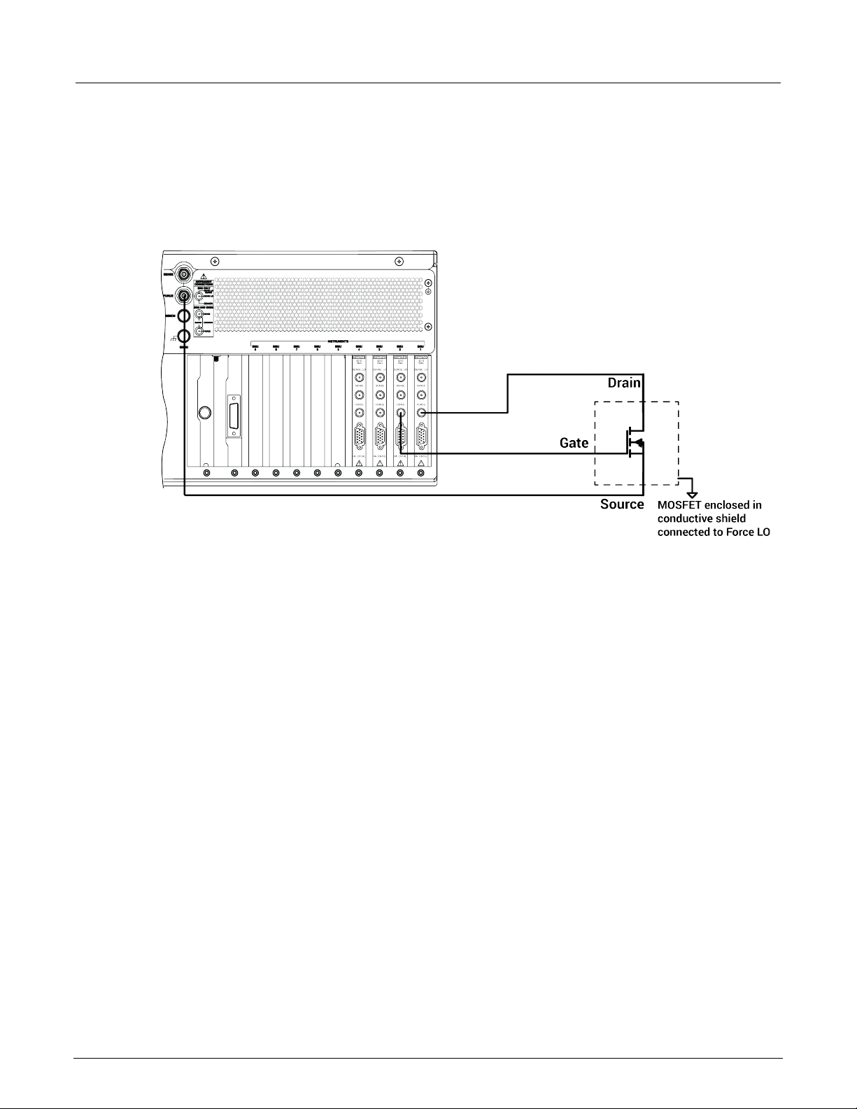
Section
User's Manual
2: Projects and tests Model 4200A-SCS Clarius
Connect the 4200A-SCS to the DUT
The hardware connections from the output of the instruments in the 4200A-SCS chassis to the test
fixture that contains the MOSFET are shown in the following figure.
Figure 19: Rear-panel connections from the 4200A-SCS to a MOSFET
Set up the measurements in Clarius
This section describes how to set up the 4200A-SCS to generate a Vds-Id family of curves for a
3-terminal n-type MOSFET. This general procedure can also be used to create tests for other devices
and other applications.
For this example, you will use the Clarius application to:
• Select and rename a new project
• Add a device
• Select a custom test
• Configure the test
• Execute the test
• View and analyze the test results
2-22 4200A-914-01 Rev. D March 2023
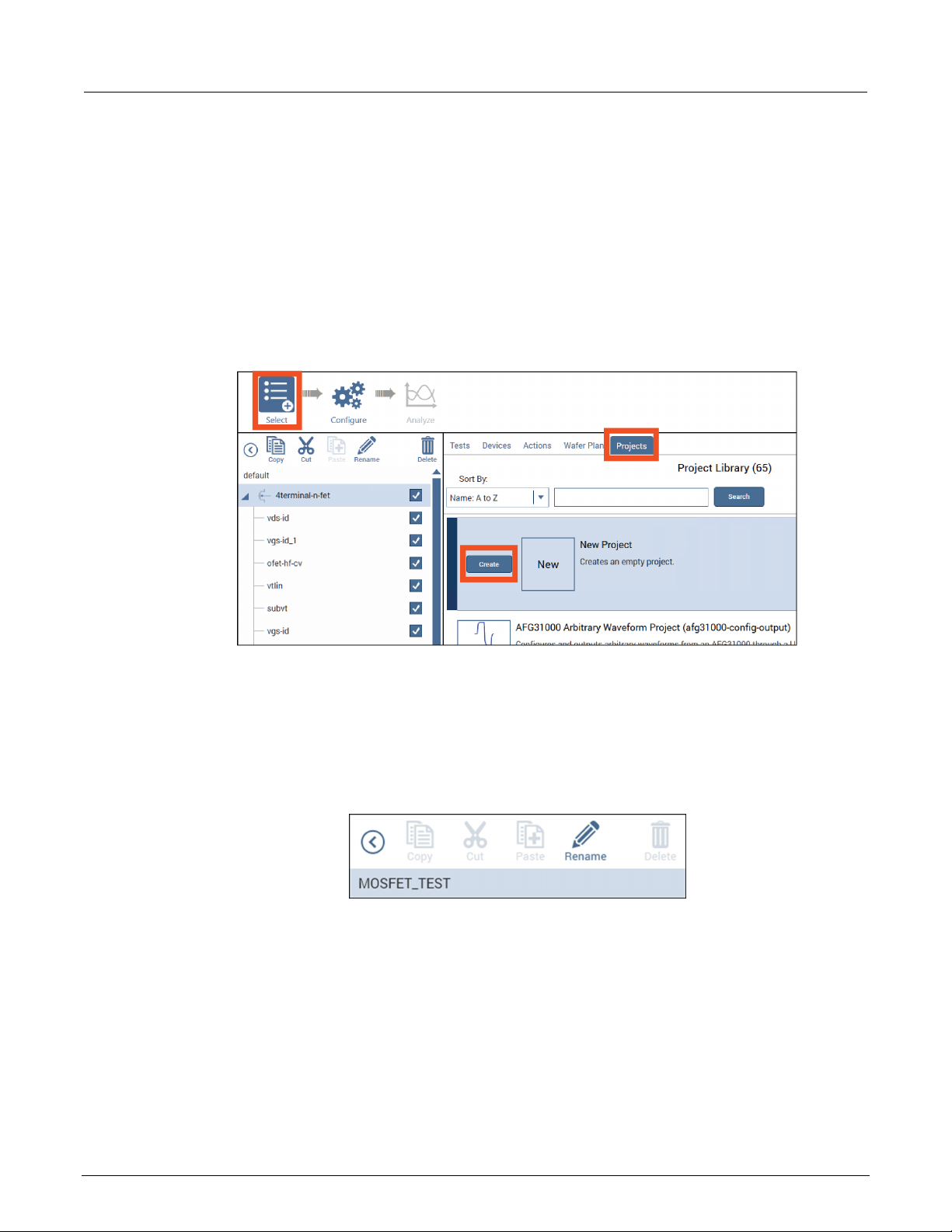
Model 4200A
Projects and tests
-SCS Clarius User's Manual Section 2:
Select and rename a new project
To select and rename a new project:
1. Choose Select.
2. In the Library, select Projects.
3. Select New Project.
4. Select Create.
Figure 20: Create new project
5. Select Yes when prompted to replace the existing project.
6. Assign a title to the project by selecting Rename above the project tree.
7. Enter a project name into the text box, then select Enter. MOSFET_TEST has been chosen for
this example.
Figure 21: Toolbar with Rename function
4200A-914-01 Rev. D March 2023 2-23
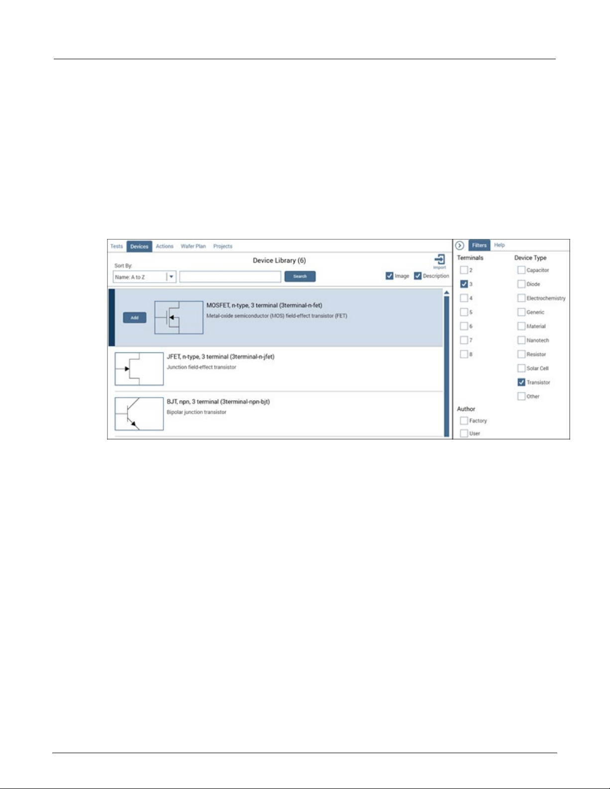
Section
User's Manual
2: Projects and tests Model 4200A-SCS Clarius
Add a device
Tests must be placed in the project under a device.
To add a device:
1. Select Devices.
2. From the Filters pane, select the 3 under the Terminals heading and Transistor under the Device
Type option.
Figure 22: Searching for a device u sing Filters
3. Select the MOSFET, n-type, 3 terminal (3terminal-n-fet) device.
4. Select Add to copy it to the project tree.
2-24 4200A-914-01 Rev. D March 2023

Model 4200A
Projects and tests
-SCS Clarius User's Manual Section 2:
Select a custom test
To select a custom test:
1. Select Tests.
2. Select Custom Test, then select Add to create a new 3-terminal, n-type MOSFET test in the
project tree.
Figure 23: Custom Test option
3. Select Rename from the toolbar. Enter a test name in the text box, then select Enter. vds-id
was chosen for this example.
Figure 24: MOSFET_TEST projec t tree with one device and one test
4200A-914-01 Rev. D March 2023 2-25
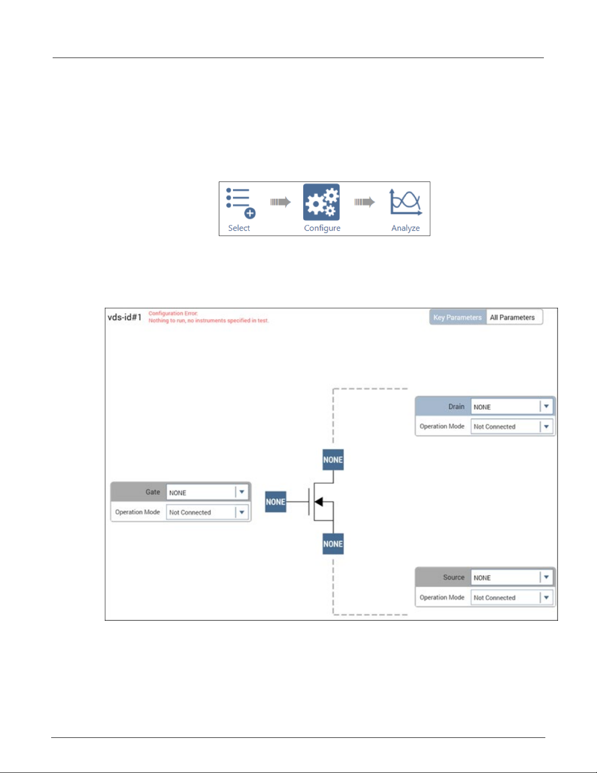
Section
User's Manual
2: Projects and tests Model 4200A-SCS Clarius
Configu re the test
To configure the test:
1. Select Configure.
2. In the project tree, select vds-id. Because this test is custom, you must assign functions to all
terminals connected to the MOSFET before you can run the test.
Figure 25: Configure highlighte d
Figure 26: All MOSFET terminals unassigned in a custom test
3. Set the Gate terminal connection to SMU2.
4. Set the Operation Mode to Voltage Step.
5. Change the Start, Stop, Step, and Compliance settings to match the following figure or to the gate
settings appropriate for your device.
2-26 4200A-914-01 Rev. D March 2023

Model 4200A
Projects and tests
-SCS Clarius User's Manual Section 2:
Figure 27: SMU2 steps from 2 V to 5 V, connected to MOSFET Gate terminal
6. Set the Drain terminal connection to SMU1.
7. Set the Operation Mode to Voltage Linear Sweep.
8. Change the Start, Stop, Step, and Compliance settings to match the following figure.
Figure 28: SMU1 sweeps from 0 V to 5 V, co nn ected to MOSFET Drain terminal
9. Set the Operation Mode of the Source terminal to GNDU.
4200A-914-01 Rev. D March 2023 2-27

Section
User's Manual
2: Projects and tests Model 4200A-SCS Clarius
Execute the test
Select Run to execute the test.
View and analyze the test results
While the test is running, you can view the data in the spreadsheet of the Analyze pane. Because you
created a new test, the data must be assigned to the axes of the graph before you can view
graphical results.
To view and analyze the test results:
1. Select Analyze. The Analyze screen displays data as it is gathered in the spreadsheet and a
blank graph with unassigned axes.
Figure 29: Run
Figure 30: Analyze highlighted
2. Select the Graph Definition Menu.
Figure 31: Graph Definition Menu
3. Select Data Series.
4. Select +. The series are assigned as shown in the following figure.
2-28 4200A-914-01 Rev. D March 2023
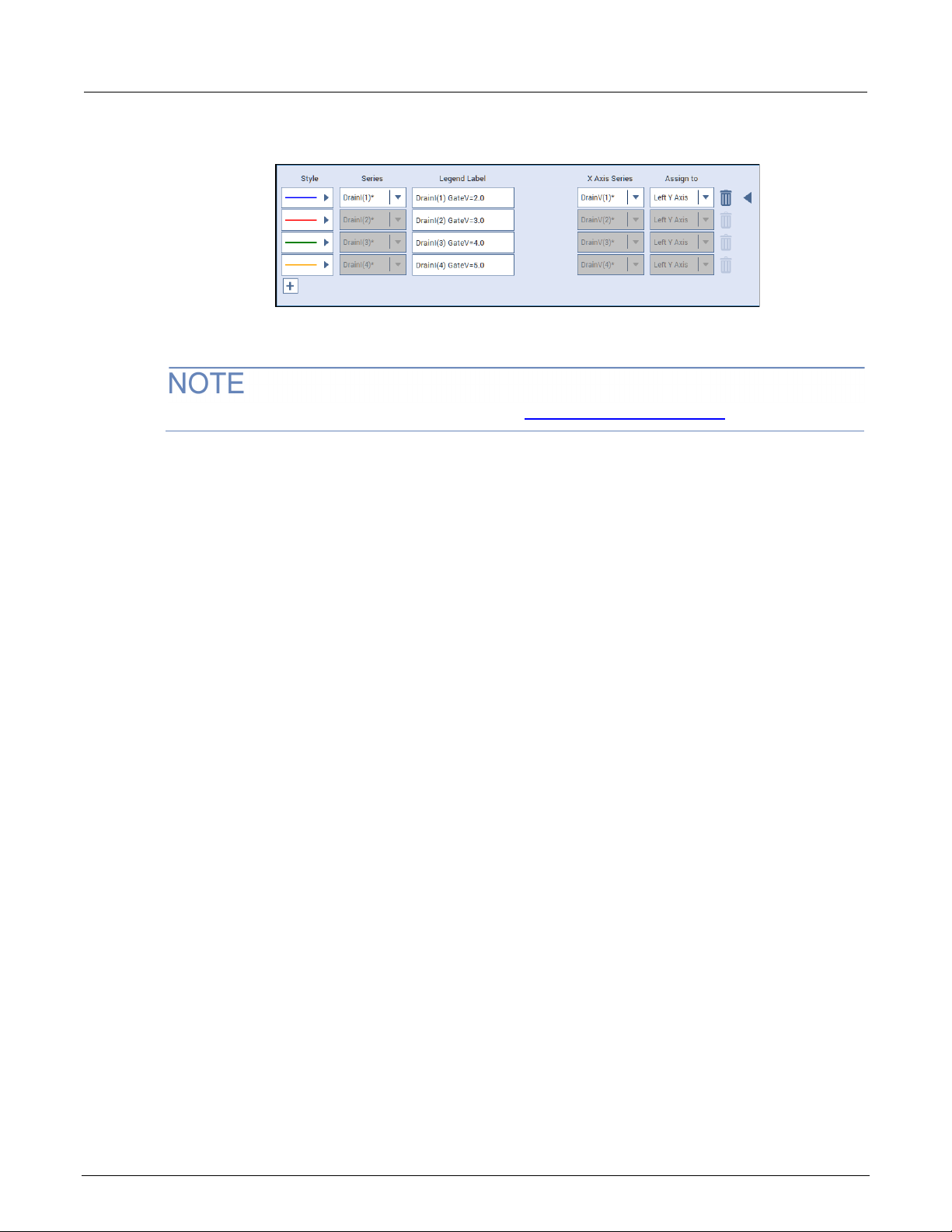
Model 4200A
Projects and tests
-SCS Clarius User's Manual Section 2:
Figure 32: Data series selected
5. Select ◄ to close the dialog. The graph displays the vds-id family of curves.
For more information on setting up a graph, refer to Analyze test data for projects (on page 3-14).
Configure a com plex test
For more complex tests, you can:
• Set advanced test and terminal parame ters .
• Set up multiple steps or sweeps to track simultaneously using masters and subordinates.
• Configure actions.
Test and terminal settings
You can access test and terminal settings from the center and right panes of Clarius when Configure
is selected.
The most common terminal settings are available in the center pane when Key Parameters is
selected. Additional common test settings are available in the right Terminal Settings pane.
Less commonly used terminal settings are available in a dialog that you open with the Advanced
button on the Terminal Settings pane.
To view all terminal settings, select All Parameters from the center pane. In this view, all terminal
settings are displayed for every terminal.
Test settings are also displayed in the right pane. Test settings affect all terminals in the selected test.
The most common settings are available in the right pane. Additional settings are available when you
select the Advanced button.
The options that are available depend on the instrument that is selected. For descriptions of
parameters, refer to:
• “SMU Test Settings” in the Model 4200A-SCS Source-Measure Unit (SMU) User's Manual
• “CVU Test Settings” in the Model 4200A-SCS Capacitance-Voltage Unit (CVU) User's Manual
• “PMU Test Settings” in the Model 4200A-SCS Pulse Card (PGU and PMU) User's Manual
4200A-914-01 Rev. D March 2023 2-29

Section
User's Manual
2: Projects and tests Model 4200A-SCS Clarius
Step or sweep multiple device terminals in the same test
Multiple steps or sweeps in an interactive test module (ITM) must track with regard to step number
and duration. For example, you might want to apply multiple steps to multiple device terminals, such
as when stepping the biases on two transistor terminals and sweeping voltage or current on the third
terminal. In this setup, Clarius automatically sets the step operations to occur simultaneously, with
one terminal set up as the master. All other step functions are automatically designated as
subordinates. The following figure illustrates this concept.
Figure 33: Master step versus subordinate step
In the following figure, the step width and the number of steps of the subordinate track the step width
and number of steps of the master sweep.
Figure 34: Master and subordinate sweeps
2-30 4200A-914-01 Rev. D March 2023

Model 4200A
Projects and tests
-SCS Clarius User's Manual Section 2:
In the following figure, the step width and number of steps of the subordinate list sweep tracks the
step width and the number of steps of the master list sweep.
Figure 35: Master list sweeps versus subordinate list sweeps
If you do not specify an instrument to be the master, the first instrument that was assigned to the step
or sweep operation mode is assigned to be the master. You can change this designation in the Test
Settings pane.
When a master is set, Clarius sets the points and step size values for the subordinate terminal to be
the same as the settings for the master terminal. You cannot change the subordinate points value for
the subordinate terminal. For list sweeps, the number of points in the list items for the subordinate is
changed to match the number of points in the master. If points are added to the master, the last point
of the subordinate list is repeated. If points are removed from the master, the same number of points
are removed from the end of the subordinate list.
4200A-914-01 Rev. D March 2023 2-31

Section
User's Manual
2: Projects and tests Model 4200A-SCS Clarius
You can have a dual sweep on a subordinate terminal even if the master is not set to dual sweep. In
this case, the dual sweep of the subordinate terminal has a total number of steps equal to the number
of steps in the master terminal. For example, if the master terminal is set to measure ten points, the
subordinate dual sweep will measure five points on the first side of the sweep and five points on the
second side of the dual sweep. If the master is set to an odd number of points, the subordinate
terminal will repeat the measurement of the last sweep point.
The subordinate SMUs are not automatically set for dual sweep when Dual Sweep is enabled for the
master SMU. Dual Sweep must be individually enabled for each SMU.
To specify the master sweep:
1. Select the test.
2. In the right pane, select Test Settings.
3. For Sweep Master, select the instrument that you want to designate as the master.
Configure actions
Settings for actions depend on the type of action that is selected. Actions can generate dialog boxes
to prompt test operator action, control prober movements, and manage switching. You can also
create your own actions from user libraries.
You can place actions anywhere in the project tree.
Information for actions is available in the Help pane. To open the Help pane, select the action in the
project tree and select Configure. Select the Help tab in the right pane.
Run a complex test
This section describes how to run individual tests, devices, subsites, and sites. It also describes how
to run the stress modes.
If Clarius detects an above-normal temperature condition at any SMU, it protects system outputs by
preventing or aborting a test run and reporting the condition in the message area of the Clarius
window. If the condition occurs when a test is attempted, Clarius prohibits execution. If the condition
occurs during a test, Clarius aborts the test.
Run devices and tests
You can execute an entire project or individual parts of the project.
While a test is running, you can view test data in the Analyze pane.
The Message area at the bottom of the center pane of Clarius displays the start time, stop time, and
total execution time of the components that were run.
2-32 4200A-914-01 Rev. D March 2023
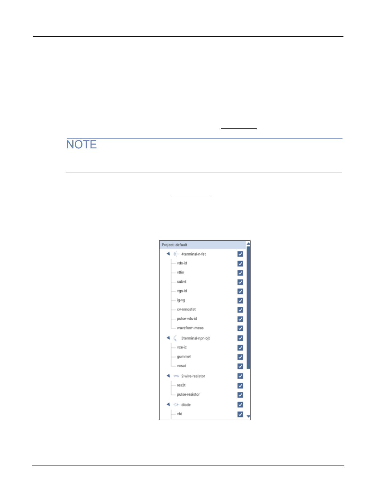
Model 4200A
Projects and tests
Run projects
-SCS Clarius User's Manual Section 2:
Executing an entire project runs its components, including sites, subsites, devices, tests, and actions,
in the order in which they appear in the project tree.
Clarius only runs items that are selected in the project tree and are at a lower level than the
highlighted item.
When you run a project, each new run creates a new test run in the Run History tab, with its own
Analyze worksheet. For more about worksheets, refer to Analyze data (on page 3-1
).
To abort a test, select Stop. All test and action execution stops immediately.The following example
uses the Demo Project to demonstrate how to run a project.
To run all objects in a project:
1. Open the Demo Project. Refer to Open a project (on page 2-8
).
2. Make sure the check boxes are selected for all items in the project tree.
3. Highlight the project name, as shown in the figure below.
Figure 36: Run a project
4200A-914-01 Rev. D March 2023 2-33

Section
User's Manual
2: Projects and tests Model 4200A-SCS Clarius
4. Select Run. The Run icon changes as shown below. The active test is listed to the left of Run.
The Stop icon changes to red.
When the test completes, a beep sounds and the run arrows around the Run icon are no
longer displayed.
Run individual devices
You can run the tests for a single device in the project tree.
When you run the tests for a single device, the tests are run in the order in which they appear in the
project tree. Only the tests that have checkboxes selected are run. In the following example, all the
tests for the diode device are run except for vrd.
Figure 37: Run icon while a test is running
To abort a test, select Stop. All test and action execution stops immediately.
The following example uses the Demo Project to demonstrate how to run tests for a device.
To run tests for a device:
1. Open the Demo Project. Refer to Open a project (on page 2-8
).
2. Make sure the check boxes are selected for all items under the diode device except for vrd, as
shown in the figure below.
3. Highlight the device name, diode, as shown in the figure below.
Figure 38: Run tests for a single d evice
2-34 4200A-914-01 Rev. D March 2023

Model 4200A
Projects and tests
-SCS Clarius User's Manual Section 2:
4. Select Run. The Run icon changes as shown below. The active test is listed to the left of Run.
The Stop icon changes to red.
When the test completes, a beep sounds and the run arrows around the Run icon are no
longer displayed.
Run an individual test
To abort a test, select Stop. All test and action execution stops immed iat ely.
To run an individual test in the project tree:
Figure 39: Run icon while a test is running
1. In the project tree, make sure the checkbox for the test is selected.
2. Highlight the test.
3. Select Run. The Run icon changes as shown below. The active test is listed to the left of Run.
The Stop icon changes to red.
Figure 40: Run icon while a test is running
When the test completes, a beep sounds and the run arrows around the Run icon are no
longer displayed.
In the following example, only the gummel test runs. Even though the other tests are selected, they
are at the same level as the gummel test in the hierarchy.
4200A-914-01 Rev. D March 2023 2-35

Section
User's Manual
2: Projects and tests Model 4200A-SCS Clarius
Figure 41: Run specific tests
You can also use Monitor to run an individual test. For more information, see Monitor a test (on
page 2-36).
Monitor a test
You can use the Monitor option to set a test to run continuously until stopped. This option is available
for ITMs and UTMs when an individual test is selected and when the Monitor option is enabled.
Enable the Monitor option
The Monitor option is enabled in My Settings.
To enable the Monitor option:
1. Select My Settings.
2. Select Run Settings.
3. Select Enable Monitor button.
4. Select OK. Monitor is now available to the left of Run, as shown in the following figure.
Figure 42: Monitor option
2-36 4200A-914-01 Rev. D March 2023

Model 4200A
Projects and tests
-SCS Clarius User's Manual Section 2:
Running a test using Monitor
When a test is run using Monitor, the test loops until you stop it. Only one test run is stored in Run
History. The stored run contains the data that was acquired during the last complete test run. The
time that is shown for the run is the time of the last completed test run, not the entire time that Monitor
was running. Runs that were generated with Monitor include "Monitor" in the description in the Run
History tab, as shown in the following figure.
Figure 43: Run History when test is run using Monitor
To use Monitor to run a test:
1. In the project tree, make sure the checkbox for the test is selected.
2. Highlight the test.
3. Select Monitor. The Monitor icon changes as shown below. The active test is listed to the left of
Monitor, followed by the number of the loop that is running. The Stop icon changes to red.
Figure 44: Monitor when a test is running
4. To stop the test, select Stop.
4200A-914-01 Rev. D March 2023 2-37
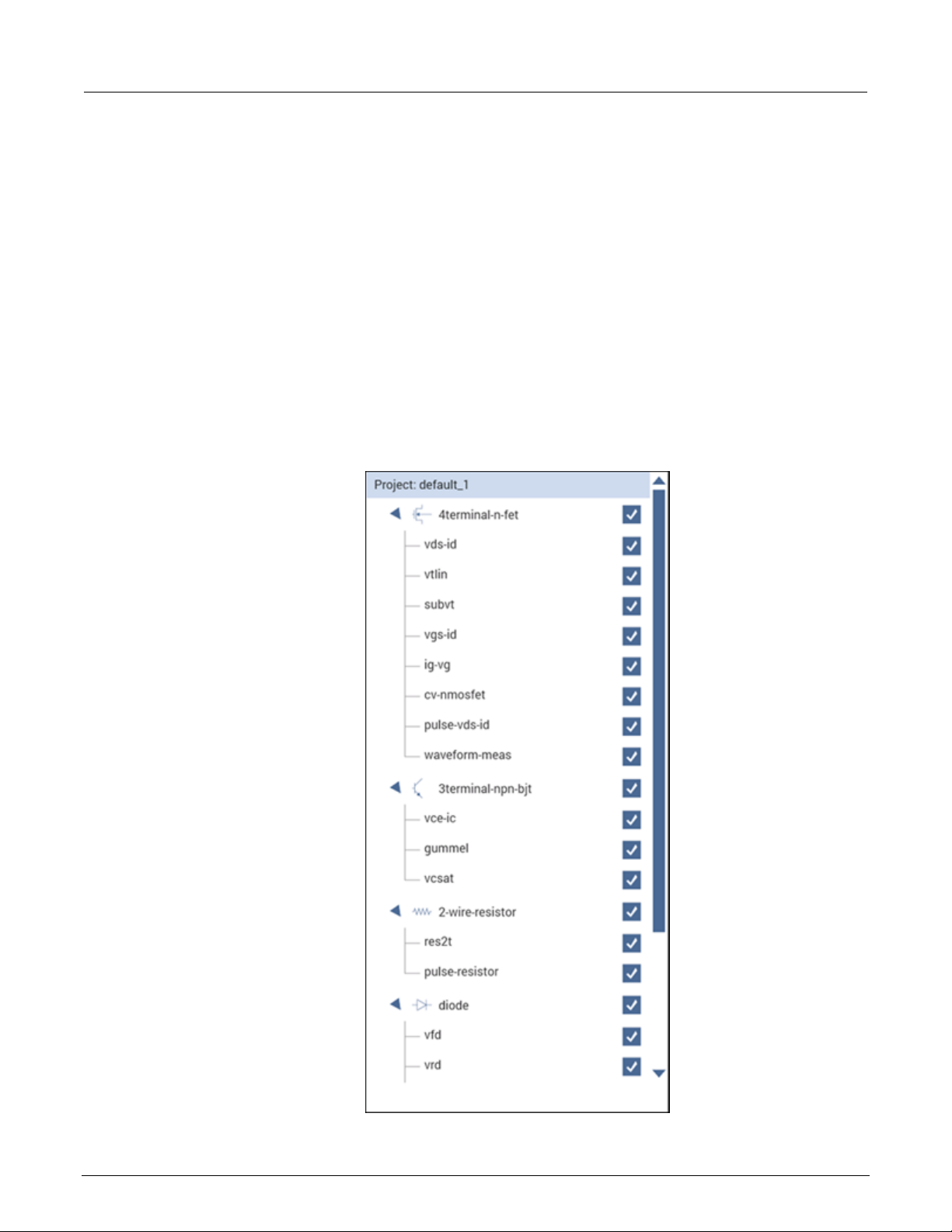
Section
r's Manual
2: Projects and tests Model 4200A-SCS Clarius Use
Demo Project overview
The Demo Project includes common dc I-V, C-V , and pulse I -V tests for MOSFETs, BJTs, resistors,
diodes, and capacitors. These tests serve as examples and are intended to be copied and modified to
work for your own devices. All test parameters in the Demo Project were written for standard discrete
parts but can be modified for use with other discrete devices or devices on a semiconductor wafer.
These tests demonstrate how to configure tests in the Configure pane, how to use Formulator
functions for common mathematical calculations and return them to the data sheet, and how to plot
the data in a variety of ways.
The Demo project opens when you first start the Clarius application.
The top portion of the project tree for the Demo project is shown in the following graphic.
Figure 45: Demo project (default) in the project tree
2-38 4200A-914-01 Rev. D March 2023
Model 4200A
Projects and tests
vds-id
This test generates the standard family of drai n current versus drain voltage curves on a
gate, drain, source, and bulk terminals of the FET.
vtlin
Uses a linear curve fit to find the threshold voltage (Vt) of a MOSFET from the generated
the gate, drain, source, and bulk terminals of the MOSFET.
subvt
Executes an I-V sweep and calculates the subthreshold voltage (sub-Vt) of a MOSFET
to the gate, drain, source, and bulk terminals of the MOSFET.
vgs-id
of a MOSFET.
ig-vg
Measures the gate leakage current of the MOSFET as a function of the sweeping gate
voltage. The test determines the gate leakage resistance using a linear line fit.
cv-nmosfet
Measures the capacitance as a function of the gate voltage between the gate terminal
thickness.
pulse-vds-id
Uses CH1 and CH2 of a PMU to generate a pulse I-V drain family of curves. CH1
measures the drain current.
waveform-meas
Uses the waveform capture mode of the PMU to show the time-based response of the
CH2 captures the transient response of the drai n current and drain vol tag e.
vce-ic
As the base current is stepped, this test measures the drain current at each point of the
terminals of the BJT.
gummel
Generates a Gummel plot as it measures both the base current and collector current of a
are connected to the base, collector, and emitter terminals of a BJT.
vcsat
At a constant base current, this test plots the collector current as a function of the
of a BJT.
-SCS Clarius User's Manual Section 2:
The following topics provide brief descriptions of the tests in the Demo project.
4-terminal n-MOSFET tests
By default, the following tests use three source-measure units (SMUs) and one ground unit (GNDU).
You can also use four SMUs, one for each device-under-test (DUT) terminal.
Descriptions of the 4-terminal n-MOSFET tests
Test Description
FET. For each gate voltage step, the test sweeps the drain voltage and measures the
resulting drain current. This test uses either three or four SMUs that are connected to the
drain current versus gate voltage data. This test uses three or four SMUs connected to
and plots drain current versus gate voltage. This test uses three or four SMUs connected
This test extracts the threshold voltage (Vt) and maximum transconductance (Gm)
parameters from a sweep of the drain current versus gate voltage. This test uses either
three or four SMUs connected to the gate, drain, source and bulk terminals
and the drain, source, and bulk terminals tied together. Several parameters are
extracted, including the flatband capacitance, doping density, flatband voltage, and oxide
outputs a pulse step output to the gate. CH2 outp uts a puls e d drain volta ge sweep and
drain current and drain voltage of a MOSFET. CH1 outputs a single pulse to the gate.
3-terminal NPN BJT tests
The tests for this device require three SMUs.
Descriptions of the 3-terminal NPN BJT tests
Test Description
drain voltage sweep. Three SMUs are connected to the base, collector, and emitter
BJT. The currents are measured as a function of the base-emitter voltage. Three SMUs
collector voltage. The data is used by the Formulator to calculate the collector saturation
voltage (V
). Three SMUs are connected to the base, collector, and emitter terminals
ce(sat)
4200A-914-01 Rev. D March 2023 2-39

Section
User's Manual
res2t
Calculates the average resistance from an I-V sweep of sourcing voltage and
can also use one SMU and GNDU.
pulse-resistor
The resistor is connected between one channel of the PMU and the PMU
current is measured.
pulse-high-resistance
The resistor is connected between CH 1 and CH 2 of the PMU (RPMs). CH1
Formulator multiples the current of CH2 by −1.
vfd
While a forward-bias voltage sweep is applied to a diode, this test measures the anode
of the line.
vrd
Sweeps the reverse bias voltage and measures the resulting current of a diode. This test
recommended that you use a SMU with the preamp option.
cv-diode
Measures the junction capacitance as a function of an applied voltage sweep. The
data.
pulse-diode
Applies a pulse voltage sweep to the anode of a diode and measures the resulting
anode current. A single channel of the PMU is used to make the measurement.
cap
Charges a capacitor at a constant current and measures the voltage as a function of
time.
cv-cap
Measures the capacitance as a function of voltage on a capacitor. The noise is
calculated using the standard deviatio n of the data.
pulse-cap
Applies a single voltage pulse to a capacitor and measures the resulting current. A single
connected to PMU1 and the other end is connected to PMU GND.
2: Projects and tests Model 4200A-SCS Clarius
Resistor tests
The following tests use two SMUs. It is also possible to use one SMU and the GNDU.
Descriptions of the 2-wire resistor tests
Test Description
Diode tests
By default, the following tests use up to two source-measure units (SMUs), a CVU, and a PMU.
measuring current. This test uses two SMUs on either side of the resistor. You
ground. Applies a pulse voltage sweep to the resistor during the test while the
applies a pulse sweep to the resistor during the test while the current is
measured by CH2. The current is derived by averaging four pulses. The
Descriptions of the diode tests
Test Description
Capacitor tests
By default, the following tests use up to two source-measure units (SMUs), one CVU, and one PMU.
Descriptions of the capacitor tests
Test Description
current and plots the data on a semi-log scale. A linear line fit is used to derive the slope
uses two SMUs on either side of the diode. You can also use one SMU and GNDU if
they are set properly in the Configure pane. For very low current measurements, it is
depletion depth (W) and the doping density (N) are calculated as a function of the C-V
channel of the PMU is used to make the measurement. One end of the capacitor is
2-40 4200A-914-01 Rev. D March 2023

Save results and graphs ........................................................ 3-31
In this section:
Introduction .............................................................................. 3-1
Spreadsheet ............................................................................. 3-2
Run History ............................................................................ 3-10
Analyze test data for projects ................................................. 3-14
Graph the data for test runs ................................................... 3-16
Introduction
When you run tests, Clarius records the data in the Analyze pane. You can display the data in a test
as a spreadsheet and as a graph. You can also select data to display and graph at the project level.
Section 3
Analyze data
Select Analyze to view the spreadsheet and graph, shown in the following figure. You can change
the display to show only the spreadsheet or only the graph using the View buttons in the upper right
of the pane.
You can use the Formulator to have Clarius extract additional parameter information from the data,
using formulas that you create. The Formulator calculation results are placed in the Run sheet, in
addition to the raw data. Refer to The Formulator (on page 6-1
) for more information.
Figure 46: Analyze
For information on analyzing data for a subsite, refer to Analyze data for subsites (on page 7-35).

Section
User's Manual
1
View selections for the Analyze pane. You can display the worksheet and the graph, the worksheet
only, or the graph only.
2
Save Data allows you to save the worksheet and graph data for the selected project, test, or action.
Refer to Save results and graphs (on page 3-31) for more information.
3
Opens the Formulator, which allows you to make data calculations on test data and on the results of
other Formulator calculations. Refer to Formulator (on page 6-1) for detail.
4
Run Settings displays the test and terminal settings used to produce the results. This is a summary of
page 3-3) for more information.
5
Tab for the test run data. If there are multiple test runs selected, you can select the tab to display the
data for that test run.
6
If there are more than three tabs, you can use these arrows to move between the worksheet tabs.
3: Analyze data Model 4200A-SCS Clarius
Spreadsheet
The Analyze spreadsheets contain the data generated by the test runs that are selected in the Run
History tab. Each run has a spreadsheet that is labeled with the name of the run. The run sheets also
record data generated by the Formulator. The run sheets are read-only.
The Analyze spreadsheet is compatible with Microsoft
If you have tests that were created in earlier versions of Clarius, you may also have a Calc sheet.
Calc sheets were used for custom, test-specific data analysis. Calc sheets created for earlier
versions are maintained in the present version of Clarius as read-only sheets.
Options on the Run worksheet
The following table provides brief descriptions of the options on the Run worksheet.
Figure 47: Options on the Run worksheet
®
Excel®.
the Test Settings and Terminal Settings that were set in Configure. Refer to Run Settings (on
3-2 4200A-914-01 Rev. D March 2023
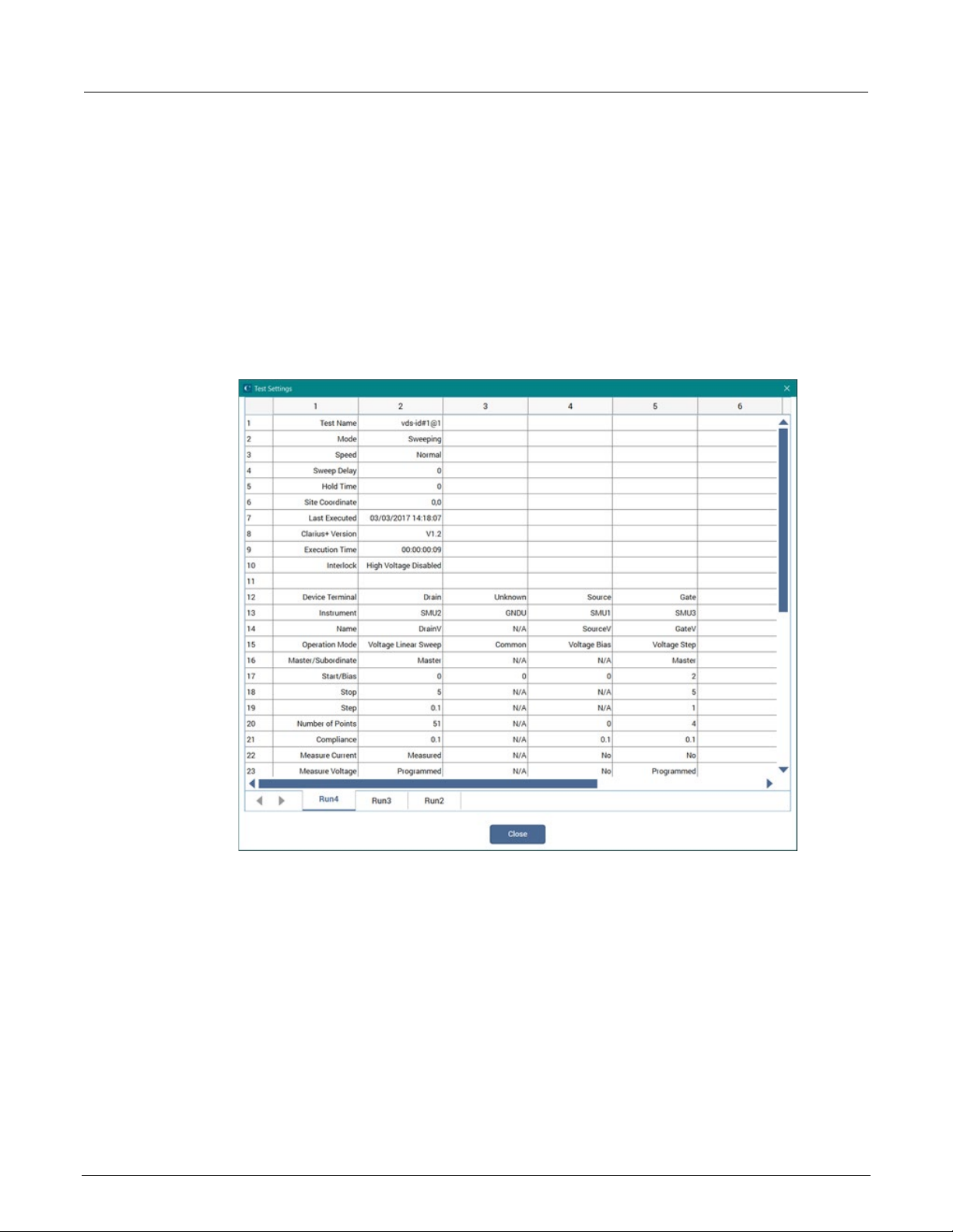
Model 4200A
Analyze data
-SCS Clarius User's Manual Section 3:
Run Settings
The Run Settings button displays the test configuration information from the Configure pane for the
test runs. If multiple test runs are selected in the Run History pane, each run is available in a separate
tab in the Test Settings dialog.
The information in the Test Settings dialog is read-only. You can select data and right-click to copy it.
An example is shown in the following figure.
Figure 48: Run Settings example
4200A-914-01 Rev. D March 2023 3-3

Section
al
3: Analyze data Model 4200A-SCS Clarius User's Manu
Run sheet
There is an Analyze Run sheet for every run of every test. Each column contains the results for one
test parameter or for a Formulator calculation.
Each column heading identifies the data in that column. Headings are assigned by the data source:
• For ITMs, Clarius assigns headings
• For UTMS, the headings are assigned by the user modules
• For Formulator calculations, the names of the formulas in the Formulator are used as
the headings
If a project contains multiple instances of a test under the same name, each instance generates its
own data. Tests are numbered in the order in which they are added to the project. Ensure that you
select the correct instance of the test in the project tree.
The figure below shows a Run sheet that contains data generated by the vds-id test.
Figure 49: Analyze Run sheet
If you have more than 32,000 data rows, the data is separated into multiple pages and the Grid Rows
list is displayed, as shown in the following figure. You can select from the list or use the arrows to
move between the pages.
3-4 4200A-914-01 Rev. D March 2023

Model 4200A
Analyze data
-SCS Clarius User's Manual Section 3:
Figure 50: Analyze Sheet with more than 32,000 rows of data
The maximum number of columns in a sheet is 256. An error is generated if a test results in more
than 256 columns.
The maximum number of rows in a sheet depends on the type of test:
• ITM maximum is 4096.
• UTM maximum is 65,535 for UTMs that use PostDataDouble if data is sent point by point.
For a test or action, you can hide columns in the graph. Right-click the column and select Hide. To
display the columns, right-click and select Unhide to choose from a list of columns, or select Unhide
All to display all columns.
If cell contains #REF, there is a problem with the data in the formulas, such a divide by zero error or
the log of a negative number. If NaN is displayed, there is a problem with the data that was acquired
during the test.
All data in the worksheets of the Analyze spreadsheet can be saved to an external file. Refer to
results and graphs (on page 3-31). To export all data from a project, test, or device, use the Data
Export tool. Refer to Data Export tool (on page 4-29).
To access the Analyze Run sheet for a project, test, or action:
1. In the project tree, select the project, test, or action.
2. Select Analyze. The sheet and graph are displayed.
3. If data is from a CVU, right-click a cell to select the CVU Data Type.
Save
4200A-914-01 Rev. D March 2023 3-5

Section
User's Manual
3: Analyze data Model 4200A-SCS Clarius
Formulas List of the Run worksheet
If a column in the Run worksheet contains the results of Formulator calculations, you can display the
formula that was used to get the results.
The #REF notation in a cell indicates that the Formulator could not calculate a valid value. This can
occur if a formula needs multiple rows as arguments, if a calculated value is out of range, or if a divide
by zero is attempted. For example, if the MAVG function is using five points to calculate a moving
average of a column that contains five values, the first two and last two cells contain #REF.
For more information on working with the Formulator, refer to Formulator (on page 6-1
To display a formula:
1. Select the Formulas List. A list of formulas is available.
2. Select the formula you want to display.
3. If you need to make changes to the formula, select Formulator to open the formula in the
Formulator.
Figure 51: Displaying a Formulator equation using the Formulas list
Terminal Settings pane (Analyze)
When Analyze is selected, the Terminal Settings pane displays the settings for each terminal used in
the presently selected test.
The options that are available depend on the instrument that is selected. For descriptions of
parameters, refer to:
).
• “SMU Test Settings” in the Model 4200A-SCS Source-Measure Unit (SMU) User's Manual
• “CVU Test Settings” in the Model 4200A-SCS Capacitance-Voltage Unit (CVU) User's Manual
• “PMU Test Settings” in the Model 4200A-SCS Pulse Card (PGU and PMU) User's Manual
Module Settings pane (Analyze)
When Analyze is selected for a test that is based on a user module, the Module Settings pane is
available. The options in this pane are the same as the options in Configure for the module. Changes
made in the Module Settings pane are also changed in Configure.
Descriptions of the options are available in the Help pane.
3-6 4200A-914-01 Rev. D March 2023

Model 4200A
Analyze data
-SCS Clarius User's Manual Section 3:
Measurement status
Many tests provide status information for the measurements in the spreadsheet of the Analyze pane.
For example, for the 42 10-CVU or 4215-CVU , t he dat a c ol umn for the status codes is l abe led CVU1S.
CVU status code indicates the current measure range for each impedance measurement and flags
any errors. You can hover on a cell to see information about the measurement.
Figure 52: Measurement status column
When a measurement error occurs, the data values in the flagged data row are color-coded to identify
the fault type as follows:
• Red: Measurement timeout.
• Magenta: Measurement overflow.
• Orange: Auto Balance Bridge (ABB) not lock ed.
An example of the color codes is shown in the following figure. In the status column (CVU1S), you
can hover over the cell to see information about the measurement.
Figure 53: Spreadsheet indicating a measurement error
4200A-914-01 Rev. D March 2023 3-7
Section
User's Manual
CVU measurement status codes (CVU1S)
#
Code
Description
0
000000yy
No faults
1
8xxxxxyy
Measurement timeout occurred
01xxxxyy
3
02xxxxyy
CVH1 voltage measurement overflow
4
03xxxxyy
CVH1 current and voltage measurement overflow
5
08xxxxyy
CVH1 ABB not locked
6
09xxxxyy
CVH1 ABB not locked, current measurement overflow
7
0Axxxxyy
CVH1 ABB not locked, voltage measurement overflow
8
0Bxxxxyy
CVH1 ABB not locked, current and voltage measurement overflow
9
xx01xxyy
CVL1 current measurement overflow
10
xx02xxyy
CVL1 voltage measurement overflow
11
xx03xxyy
CVL1 current and voltage measurement overflow
12
xx08xxyy
CVL1 ABB not locked
13
xx09xxyy
CVL1 ABB not locked, current measurement overflow
14
xx0Axxyy
CVL1 ABB not locked, voltage measurement overflow
15
xx0Bxxyy
CVL1 ABB not locked, current and voltage measure me nt overflow
yy value
00
Lowest range (1 μA) used for the impedance measurement
01
Middle range (30 μA) used for the impedance measurement
02
Highest range (1 mA) used for the impedance measureme nt
3: Analyze data Model 4200A-SCS Clarius
Status codes
The 16 basic codes used for CVU measurement status are listed in following table. Each code is
represented as a 32-bit hexadecimal value (0x).
2
CVH1 current measurement overflow
The yy value indicates the range used, as shown in th e follow ing ta ble.
Enabl e status code s for SMUs
Status codes are automatically available for CVUs, PGUs, and PMUs. For SMUs, you must choose to
display the status codes. When this option is selected, Clarius records measurement status
information when the test executes. A column of the Analyze spreadsheet displays this information.
Hover over a cell to review the information. An example of the status information is displayed in the
following figure.
3-8 4200A-914-01 Rev. D March 2023

Model 4200A
Analyze data
-SCS Clarius User's Manual Section 3:
Figure 54: SMU Report Status column in the Analyze sheet
To display status codes for a SMU:
1. In the project tree, select the test.
2. Select Configure.
3. Select Terminal Settings in the right pane.
4. Select Advanced.
5. Select Report Status.
Measurement status notes
Whenever a fault occurs, run the Confidence Check utility before performing any other
troubleshooting actions (see CVU Confidence Check (on page 4-24
Measurement timeout: Indicates that the measurement was not received after a set time (total
aperture). This timeout error may indicate that there is an issue with the CVU card. Try resetting the
hardware and running the project test again. If this error reoccurs, contact Keithley Instruments.
To reset the hardware:
1. Select Start.
2. Type resethw.
3. Select the instruments that need to be reset.
4. Select Reset.
Current measurement overflow:
) for details).
• Try a higher current measure range (or Auto).
• Try a lower ac drive voltage.
Voltage measurement overflow: Try a lower dc bias voltage.
4200A-914-01 Rev. D March 2023 3-9

Section
User's Manual
3: Analyze data Model 4200A-SCS Clarius
ABB unbalance errors
The CVU uses the autobalancing bridge (ABB) technique to achieve accurate impedance
measurements. ABB creates a virtual ground at the DUT to minimize measurement error. Every CVU
measurement is made with ABB active. The ABB always attempts to lock the low side of the DUT to
virtual ground.
If the ABB fails to lock, the measurement is made, but may be out of specification. If this occurs, the
returned data is flagged and shown in yellow on a blue background on the Analyze sheet.
The most common reasons that ABB fails to lock are:
• The cable lengths on the CVU terminals are not the same
• HPOT or LPOT terminals were disconnected
• Excessive noise on the LPOT terminal
• High frequency sources
• Physical cable lengths do not match the cable length set in Clarius
• Improperly torqued SMA cables
• Sub-optimal I
• Too much parasitic load on the low side of the DUT
You can use CVU Confidence Check to help troubleshoot ABB errors. Refer to
and short check (on page 4-24) for instructions on performing a confidence check.
Run History
When a test is selected in the project tree and Analyze is selected, the right pane includes a Run
History tab. If the test is one of the pre-built tests, Run History contains reference data and the
Analyze pane displays a sample graph. If you created a new test, there is no information in the Run
History pane or graph until the test is run.
If you ran the test, the latest test run is displayed at the top of the Run History pane. The data and
graph from this test run are displayed in the Analyze pane.
You can have up to 10,000 runs for each test and you can select up to 128 test runs from the Run
History to be displayed in the Analyze pane. The data for each selected test run is shown in a
separate tab in the Analyze sheet. All the selected test runs are graphed on the Analyze graph. By
default, the latest test run data and graph are displayed in the Analyze sheet and graph. Select a
different test run to view that information in the Analyze sheet and graph.
RANGE
setting
Run an open check
When you run stress subsite operations, only data from the latest loop is saved to the Run History
data file in a test. The oldest run is removed first. This optimizes disk space usage.
3-10 4200A-914-01 Rev. D March 2023

Model 4200A
Analyze data
-SCS Clarius User's Manual Section 3:
Each Run History entry includes:
• A timestamp that shows the date and time when the test was run.
• The execution time.
• Rating stars that you can use to flag specific tests.
• Notes.
• The indicator "Monitor" if the data was generated using the Monitor option.
Figure 55: Run History pane
If you imported data from a 4200 project, each set of appended data is shown as a separate test run
in the Run History.
Change the name of a test run
You can change the name of the test run. If you change the name, the new name is displayed in the
following locations:
• The data tab name in the Analyze sheet.
• In the Formulator in the Formula Set list.
• In the test library if you add the test to the test library.
4200A-914-01 Rev. D March 2023 3-11

Section
al
3: Analyze data Model 4200A-SCS Clarius User's Manu
The names for test runs:
• Must be less than 19 characters.
• Must be unique; multiple test runs cannot have the same name. The name comparison is not
case-sensitive. For example, Best and best are considered to be the same name.
• Must not use Clarius reserved names, including Data, Calc, Settings, and Run1 to Run9999.
To change the name of a test run:
1. In the Run History pane, select More.
2. In the Run number text box, type the new name.
3. Select Enter. The name you entered is displayed, followed by the run number.
To revert to the default name, clear the information in the Run number text box and select Enter.
Delete test runs from Run History
You can delete test runs from the Run History, including reference data. This deletes the data
from Clarius.
If you are deleting multiple test runs, only the highlighted test runs are deleted. The status of the
checkbox does not affect what is deleted.
To delete a test run from the Run History:
1. Right-click the Run History and select Delete.
2. Select Yes.
To delete multiple test runs:
1. Highlight the test runs to be deleted. You can use Ctrl+click and Shift+click to highlight them.
2. Right-click and select Delete Selected.
To delete all test runs, including reference data:
Right-click in the Run History pane and select Delete All.
3-12 4200A-914-01 Rev. D March 2023

Model 4200A
Analyze data
-SCS Clarius User's Manual Section 3:
Working with the Run History pane
You can change the sort order of the test runs in the Run History tab using the options at the bottom
of the Run History tab. Select Date, Name, Checked, or Stars to sort the test runs in ascending or
descending order using that option.
If you have more than one pane of test runs, use the arrow buttons to move between the panes.
To highlight a group of test runs, right-click and select Begin Select Range. To select a range,
highlight another test run and right-click and select End Select Range. To clear the selections,
right-click and select Clear Selected.
Searching for a test run
You can search for a test run by date.
To search for a test run by date:
1. At the bottom of the Run History pane, enter the date.
2. Select Date Search.
Add notes to a test run
To add notes to a test run:
1. Select More.
2. Enter the note into the text box below Less.
3. Select Enter when the notes are complete.
Copy the settings of a test run to the Configure screen
You can copy the test and terminal settings that were used to generate a test run to the Configure
pane. All settings in the Configure pane are replaced by the settings from the selected test run. This
allows you to quickly restore the settings that were used to generate a test run.
To copy the settings:
1. In the Run History pane, right-click the test run that contains the settings you want to use.
2. Select Load Configuration. The changes are made to the Configure pane.
4200A-914-01 Rev. D March 2023 3-13

Section
User's Manual
3: Analyze data Model 4200A-SCS Clarius
Setting the Run History size
You can set the maximum number of test runs that are stored and displayed in the Run History pane.
When you run a test, the number of test runs stored in the Run History is limited to the number that is
set. To maintain the number of runs, Clarius deletes the oldest unselected run. If there is existing data
that exceeds the limit, only the oldest unselected run is deleted. If you have all runs selected, the
most recent run is deleted when a new run is created. The runs continue to be numbered
sequentially.
For example, if you have 200 existing runs and change the maximum run history size to 5, the
number of runs in the Run History remains at 200. The next test run triggers the deletion of the oldest
unselected run. The new run is numbered 201.
If you are running a project with subsite cycling or stressing, all existing runs are automatically
unselected at the start of execution. Only data collected during the last run of the project is selected
and displayed on the graphs. To save data between project runs, increase the run history size to be
more than the number of cycles or stresses in your project.
If the run history size setting is less than the number of cycles or stresses in your project, a run is still
generated for each cycle or stress.
To set the number of test runs stored in Run History:
1. In Clarius, select My Set tings.
2. Select Run Settings.
3. In Run History Size, enter the number of runs (1 to 10,000).
4. Select OK.
Analyze test data for projects
You can select test data to display at the project level. This allows you to compare data from different
tests in your project in the sheet and graph.
You can also use the Formulator at the project level. The Formulator allows you to make data
calculations on test data and on the results of other Formulator calculations. Refer to The Formulator
(on page 6-1) for information on creating formulas.
When you look at a graph at the project level, you cannot view multiple test runs from the same test
and family curves functionality is not available. Other graph settings are available as described in
Analyze data for test runs (on page 3-1
).
Save the project to preserve the Formulator and graph settings with the project.
3-14 4200A-914-01 Rev. D March 2023

Model 4200A
Analyze data
-SCS Clarius User's Manual Section 3:
Select data for the project-level Analyze pane
You can select up to 255 columns of data to display in the project-level Analyze pane.
To select test data to display at the project level:
1. Select Analyze.
2. In the project tree, select the project.
3. In the right pane, select Data Series.
4. From Device, select the device that contains the data.
5. From Test, select the test that contains the data.
6. From Run History, select the test run that contains the data. To display the most recent data,
select LatestRun.
7. From Data Series, select All to display all available data or select a specific set of data.
8. Select Add.
The data is displayed in the Analyze pane. The selected data series is also listed in the Series List at
the bottom of the right pane.
The data for each selected device, test, and run is grouped in the Sheet. Scroll to the right to view
the data.
You can select any of the data for graphing. See Define data to be graphed (on page 3-19
) for detail.
An example of a project with data and a graph set up is shown in the following figure.
Figure 56: Analyze for a project
4200A-914-01 Rev. D March 2023 3-15

Section
User's Manual
3: Analyze data Model 4200A-SCS Clarius
Remove data from the project-level Analyze pane
You can remove data from the project-level An aly ze sh eet and gr aph. The orig ina l data
remains intact.
To remove data from the project-level Analyze display:
1. In the Series List in the right pane, select the device, test, or run. You can use Ctrl+click to select
multiple indiv id u a l items or Shift+click to select a series of items.
2. Select Remove.
To remove all data from the project-level Analyze display:
In the Series List in the right pane, select Remove All.
Graph the data for test runs
The Analyze graph allows you to create graphs of test results. The graph provides you with flexible
plot-data selection, formatting, annotation, and numerical coordinate display using precision cursors.
For test runs, the graph displays the data from the Run sheet tabs for the test runs selected from Run
History. Each test run updates the graph to display the latest set of data. See Run History
3-10) for detail on selecting the runs that are displayed on the graph.
You can change the format of the graph using the options in the Graph Definition Menu.
If you are viewing data for a subsite, refer to Analyze data for subsites (on pag e 7-35) for information
on the graphing options for the subsite.
Open a graph
To open a graph:
1. In the project tree, select a test.
2. Select Analyze. The graph is displayed at the bottom of the center pane. The time and date when
the data was generated are displayed in the upper left corner.
3. To enlarge the graph, select the Graph only option:
(on page
3-16 4200A-914-01 Rev. D March 2023

Model 4200A
Analyze data
Graph Definition Menu. Accesses options that you can use to customize the graph. You can also
access this menu by right-clicking the graph. See Customize the graph (on page 3-18).
Right Y-axis settings. Only displayed if the Right Y Axis Definition is set up. See Define graph axes (on
page 3-20).
Line Fit information. Only displayed if Line Fits are selected. See Line fits (on page 3-27).
X-axis settings. See Define graph axes (on page 3-20) to customize the axis.
Text added to the graph from the Graph Definition menu Add Text option. See Add text to the graph
(on page 3-24).
The date and time when the data was generated.
-SCS Clarius User's Manual Section 3:
Figure 57: Example of n-MOSFET drai n family of curves graph
Options on the graph
The following table provides brief descriptions of the options on the Analyze graph.
Figure 58: Example of an Analyze graph
1
2
3
4
5
6
Left Y-axis settings. See Define graph axes (on page 3-20
) to customize the axis.
7
4200A-914-01 Rev. D March 2023 3-17
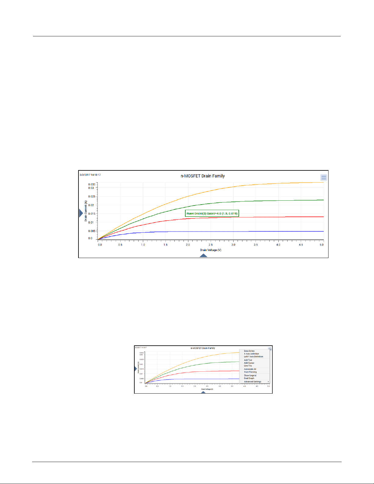
Section
User's Manual
3: Analyze data Model 4200A-SCS Clarius
View detail on a data point
When you select a point on any graph, Clarius displays the following information about the point:
• Run name, such as Run 4.
• Legend name, which includes the column name, such as DrainI(4). If a family of curves is
graphed, it also includes the family curve name, such as GateV=5.0.
• Graph coordinates
This feature allows you to check information about any point on the graph. An example is shown in
the following figure.
Figure 59: Data point display
To zoom in on data, on a touch screen, pinch. If you are using a mouse, select a portion of the graph.
To return to the full graph view, double tap or double-click.
Customize the graph
You can customize the graph using options in the Graph Definition Menu. You can also access these
settings by right-clicking the graph.
Figure 60: Graph Definition Men u
3-18 4200A-914-01 Rev. D March 2023
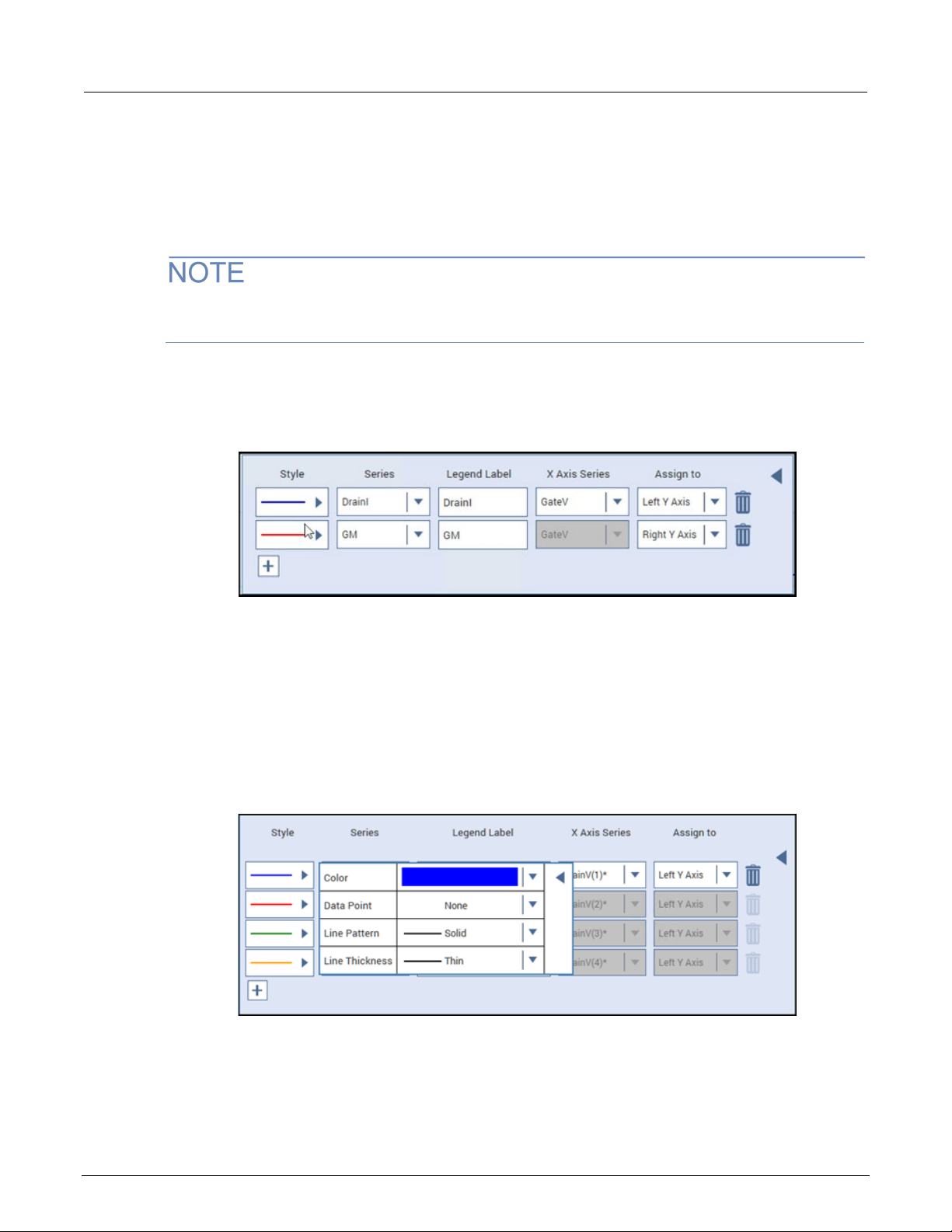
Model 4200A
Analyze data
-SCS Clarius User's Manual Section 3:
Define data to be graphed
You can add or change the data series that is graphed and which axis it is displayed on.
When you set the style for a test run, the next test run uses the same style. If you compare multiple
test runs, the line pattern changes for each run to make it easier to distinguish the runs in the graph.
If no test runs are selected in Run History, you can define the data to be graphed as described in the
following procedure. The settings you make are applied to the next run.
To select the data series for the graph:
1. From the Graph Definition Menu, select Data Series.
Figure 61: Data Series dialog
2. To add a data series to the graph, select +. The next column of data from the sheet is added.
3. For Series, select the data series to be displayed on the y-axis.
4. For Legend Label, enter the text that is displayed in the legend when it is selected.
5. For X Axis Series, select the data series to be displayed on the x-axis.
6. For Assign To, select which the y-axis to display this data series on.
7. For Style, select ►. The options shown in the following figure are displayed.
Figure 62: Data Series Style opti o ns
8. Select the ▼ next to the Color, Data Point, Line Pattern, and Line Thickness to set each of the
style options.
9. When changes are complete, select ◄ to close the dialog. The settings are applied immediately.
4200A-914-01 Rev. D March 2023 3-19
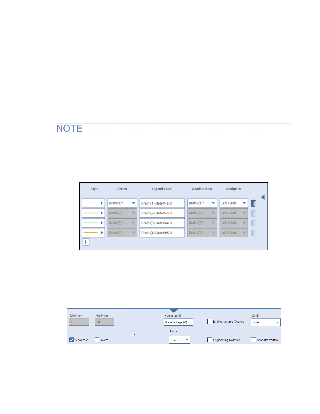
Section
al
3: Analyze data Model 4200A-SCS Clarius User's Manu
To remove a data series from the graph:
1. Select the trash can icon for that series.
2. If you select a new data series, the Legend Label is now reset to the defaults.
Define a family of curves
For tests that generate a family of curves, the family of curves is treated as one data series. Deleting
or adding one series deletes or adds them all. You can change the style and legend for an individual
data series in a family of curves.
If there are multiple parameters with the same name, an * is displayed after the parameter name in
the data series dialog.
An example of the Data Series dialog for a family of curves is shown in the following figure.
Figure 63: Data Series for a family of curves
Define graph axes
You can change the settings for the graph axes using the Axis Definition options in the Graph
Definition Menu or by selecting the triangles on the bottom and sides of the graph. An example of the
options for the X-axis is shown in the following figure.
Figure 64: Graph X-axis options
Minimum and Maximum set the graph to display only data between these two values. These options
are not available if Autoscale is selected.
3-20 4200A-914-01 Rev. D March 2023

Model 4200A
Analyze data
-SCS Clarius User's Manual Section 3:
Autoscale automatically scales the axes to best fit the data. When you select Autoscale, the
Minimum and Maximum settings are set to the autoscale values.
Invert allows you to flip the orientation of the graph so that the lowest value is at the top of the Y axis
or the right side of the X axis.
The Label is the text that identifies the axis.
The Units option selects the unit of measure (volts, amps, seconds, farads, Siemens, or Hertz) that is
displayed on the axis. When a unit of measure is selected, you can also set how the value is
displayed, such as in A, mA, or µA. When Engineering Notation is selected, the Auto option is
available. In this case, the graph automatically adjusts the units of measure for the best presentation
of the data.
Engineering Notation displays the scale values and cursor data points in engineering notation.
When this option is cleared, the scale values and data points are displayed in either standard form or
scientific notation, depending on the value.
Scale allows you to display the data on a linear or logarithmic scale. If Log is selected, Absolute
Values is automatically set. If you return to Linear, you may need to clear Absolute Values if you want
to graph negative values.
Absolute Values graphs the data as unsigned values when selected.
The X-axis also includes the Enable Multiple X Series option. This allows you to select additional X
Axis Series data in the Data Series dialog. Refer to Define data to be graphed (on page 3-19
additional information. When you clear Enable Multiple X Series, the X Axis Series changes to the
value of the first series shown in the Data Series dialog.
Display multipl e r uns
You can display multiple run histories in the Analyze graph and select how to differentiate the data for
appended run histories. Appended run histories are run histories that are added to a graph that
already has a selected run history. Options for differentiating the data from different runs include
using combinations of line styles, line colors, and data point markers. You can set the differentiation
for each graph in each test independently, as described in the following, or use the default method
described in Set the Clarius graph defaults (on page 3-23
change the individual data series without affecting the graphs of the other run histories.
In the example in the following figure, Run3 and Run2 are appended runs. The series from appended
runs use the same colors as the first selected run (in this example, Run4), but are differentiated by
line styles. In this figure, the Run3 series uses the long dash line style and the Run2 series uses the
dotted line style.
). If you set up defaults, you can later
) for
4200A-914-01 Rev. D March 2023 3-21

Section
User's Manual
3: Analyze data Model 4200A-SCS Clarius
Figure 65: Example of multiple runs
Change the append style for multiple run histories
If the append style is not changed for the graph in the selected test, it is set to the default described
in Set the Clarius graph defaults (on page 3-23
To change the line style when multiple run histories are graphed:
1. From the Graph Definition Menu, select Advanced Settings.
2. Select the line or point option:
Append by Line Style: Use a different line style, such as line, dotted line, or dashed line, for
the data from each run history.
Append by Line Color: Use a different line color for the data from each run history.
Append by Point Markers: Use different point markers for the data from each run history.
).
3-22 4200A-914-01 Rev. D March 2023

Model 4200A
Analyze data
-SCS Clarius User's Manual Section 3:
Return to graph defaults for selected run histories
You can reset the data series for the selected run histories. The default settings for the most recent
run are a blue line, no data point marker, solid line pattern, and thin line thickness.
If you select more than one data series in the run, the following series are plotted in different colors.
If more than one run history is selected, the appended run histories are returned to the default
append styles for this graph in the test.
To return to the graph defaults for the selecte d run histories:
1. From the Graph Definition Menu, select Advanced Settings.
Set appended run history graphed data to match the most recent run his tory
2. Select Set Data Series to Defaults.
You can set the graphed data of appended run histories to use the settings of the first selected run
history as a template. This does not change settings for the first (not appended) run history.
You can use this feature to customize the series of the first run and synchronize all appended runs to
its settings.
To set the display of appended run histories to match the most recent selected run history:
1. From the Graph Definition Menu, select Advanced Settings.
2. Select Reset Appended Data Series.
Set the Clarius graph defaul t s
When you select multiple run histories for display on the Analyze graph, the lines for each run are
differentiated by the line style, line color, or point markers.
If you do not define the append style for a specific test using the Graph Definition Menu, Clarius uses
the style selected for the Default Append Style.
To set the append style defaults:
1. On the top pane of Clarius, select My Settings.
2. Select Graph Defaults.
3. Set the Default Append Style to the default style.
4. Select OK.
4200A-914-01 Rev. D March 2023 3-23

Section
User's Manual
3: Analyze data Model 4200A-SCS Clarius
Add text to the graph
You can add up to four text boxes to the graph. You can use Latin character sets in the text.
Each text box can contain up to 512 characters in up to 12 lines of text.
To add text:
1. Select the Graph Definition Menu.
2. Select Add Text. The Add Text dialog is displayed, as shown in the following figure.
Figure 66: Graph Add Text dialog
3. In the Text box, enter the text.
4. Select the Font Size.
5. Select the Color.
6. To include the date and time when the data was generated, select Add Date & Time.
7. To add the value from a data series, select the data series from the list, then select Add Series
Value.
8. Select OK.
9. Drag the text to the appropriate location on the graph.
3-24 4200A-914-01 Rev. D March 2023

Model 4200A
Analyze data
-SCS Clarius User's Manual Section 3:
The following figure shows an example with a series (LatestRun:VT) and the date and time
(Date&Time) options added.
Figure 67: Add Text dialog with date, time, and series values included
The following figure shows how the Edit Text settings in the previous figure are displayed on
the graph.
Figure 68: Example of a text box on the graph
To edit text:
Double-click the text to open the Edit Text dialog.
To remove text:
Right-click the text and select Remove Text. The text is removed from the graph and deleted from
the Edit Text dialog.
4200A-914-01 Rev. D March 2023 3-25

Section
User's Manual
3: Analyze data Model 4200A-SCS Clarius
Add cursors to the graph
You can add up to two sets of cursors to the graph.
When cursors are displayed, the following information is displayed next to the cursor:
• The data series.
• The cursor coordinates.
To add cursors to the graph:
1. From the Graph Definition Menu, select Add Cursor.
2. Select the line for the cursor and drag it as needed to view the data. An example is shown in the
following figure.
Figure 69: Graph cursors
To remove cursors from the graph:
1. Right-click the line for the cursor.
2. Select Remove cursor.
Display the graph legend
You can display a legend that describes each series of data.
To display the legend, right-click the graph and select Show Legend. You can drag the legend to a
new location on the graph.
To change the labels of t he legend, se lec t th e ar row o n the leg end. T his op ens th e Data Series dialog,
which you can use to change the line style, data series, label, and axes. The legend label can be up
to 32 characters.
To hide the legend, right-click the legend and select Hide Legend.
To change the size of the text on the legend:
1. From the Graph Definitio n Menu , sel ect Advanced Settings.
2. Select the Legend Font Size (small, medium, or large).
3-26 4200A-914-01 Rev. D March 2023

Model 4200A
Analyze data
-SCS Clarius User's Manual Section 3:
Display two graphs
You can display two graphs with different data series.
You can also hide one of the graphs. The settings for the hidden graph are retained.
To display two graphs:
1. In the Graph Definition Menu, select Dual Graph.
2. Use the options in the Graph Definition Menu for the second graph to set up the graph.
To hide one of the graphs:
1. Select the Graph Definition Menu for the graph you want to hide.
2. Select Hide Graph.
3. To redisplay the graph, select Dual Graph.
Line fits
You can use the graph line fit feature to create lines that have the best fit to a series of data points.
Line fits are used to study the nature of the relation between multiple variables.
Add line fits
You can fit lines to test result graphs for one or two line fits between existing cursors. When the line is
fitted, the graph displays:
• The fitted line.
• The fit parameters in a text box on the graph.
• The point at which a tangent line is fitted to the plot or the starting and ending points (data range).
• The data-point coordinates.
When you add a line fit, a dashed line is displayed, along with cursors that you can drag to a new
location on the line. If you select the Free Linear line fit type, you can drag the cursors to any point on
the graph.
A text box is displayed for each line fit. You can move this text box as needed. The text box contains
the fit parameters and cursor coordinates.
4200A-914-01 Rev. D March 2023 3-27

Section
al
3: Analyze data Model 4200A-SCS Clarius User's Manu
To add a line fit:
1. Select Analyze.
2. Select the Graph Definition Menu and select Line Fits.
Figure 70: Line Fits dialog
3. Select Enable for the line fits you want to display.
4. Select the Data Series for each line fit. If you are selecting the Free Linear line fit type, you select
the Left Y Axis or, if it is defined, the Right Y Axis as the data series.
5. Select the Line Fit Type. You can select:
Linear: Chord line of the form y = a + bx.
Linear Regression: Regression line of the form y = a + bx.
Exponential: Regression line of the form y = a * e^bx.
Log: Regression line of the form y = a + b * log10(x).
Tangent: Tangent to the plot. The tangent line has the form y = a + bx.
Free Linear: Add a line fit that is not constrained to a specific data series.
6. Select the Font Size.
7. Select the Color of the line and text box.
8. Select Show Label to display a text box with the line fit coordinates.
9. Select OK. The line fits are displayed on the graph.
10. If you selected Show Label, you can drag the text box with the coordinates to a new location.
3-28 4200A-914-01 Rev. D March 2023

Model 4200A
Analyze data
Text box that contains the parameters of the linear regression fit line and the cursor coordinates. You
can move this box.
Linear regression fit line.
Cursors for the data points that define the linear regression fit line. You can move the cursors along
Log fit line.
Cursors for the data points that define the log fit line. You can move the cursors along the line.
Text box that contains the parameters of the log fit line and the cursor coordinates. You can move
this box.
Linear
LINFIT
LINFITYINT
LINFITSLP
LINFITXINT
Linear Regression
REGFIT
REGFITYINT
REGFITSLP
REGFITXINT
Exponential
EXPFIT
EXPFITA
EXPFITB
Not applicable
Log
LOGFIT
LOGFITA
LOGFITB
Not applicable
Tangent
TANFIT
TANFITYINT
TANFITSLP
TANFITXINT
-SCS Clarius User's Manual Section 3:
Line fit examples
The following figure illustrates the linear regression and log line fit types.
Figure 71: Linear fit example
1
2
3
4
5
6
the line.
Formulator line fits
The Formulator also includes options to generate line fits. The Formulator fit results can be used in
other calculations. The results of the graph line fits are similar to the results with the corresponding
Formulator functions, as shown in the following table.
Correspondence between graph and Formulator line fits
Graph line fit Formulator fits that return the corresponding fit line and fit parameters
Fit line Fit parameter "a" Fit parameter "b"
Fit parameter
"xint"
4200A-914-01 Rev. D March 2023 3-29
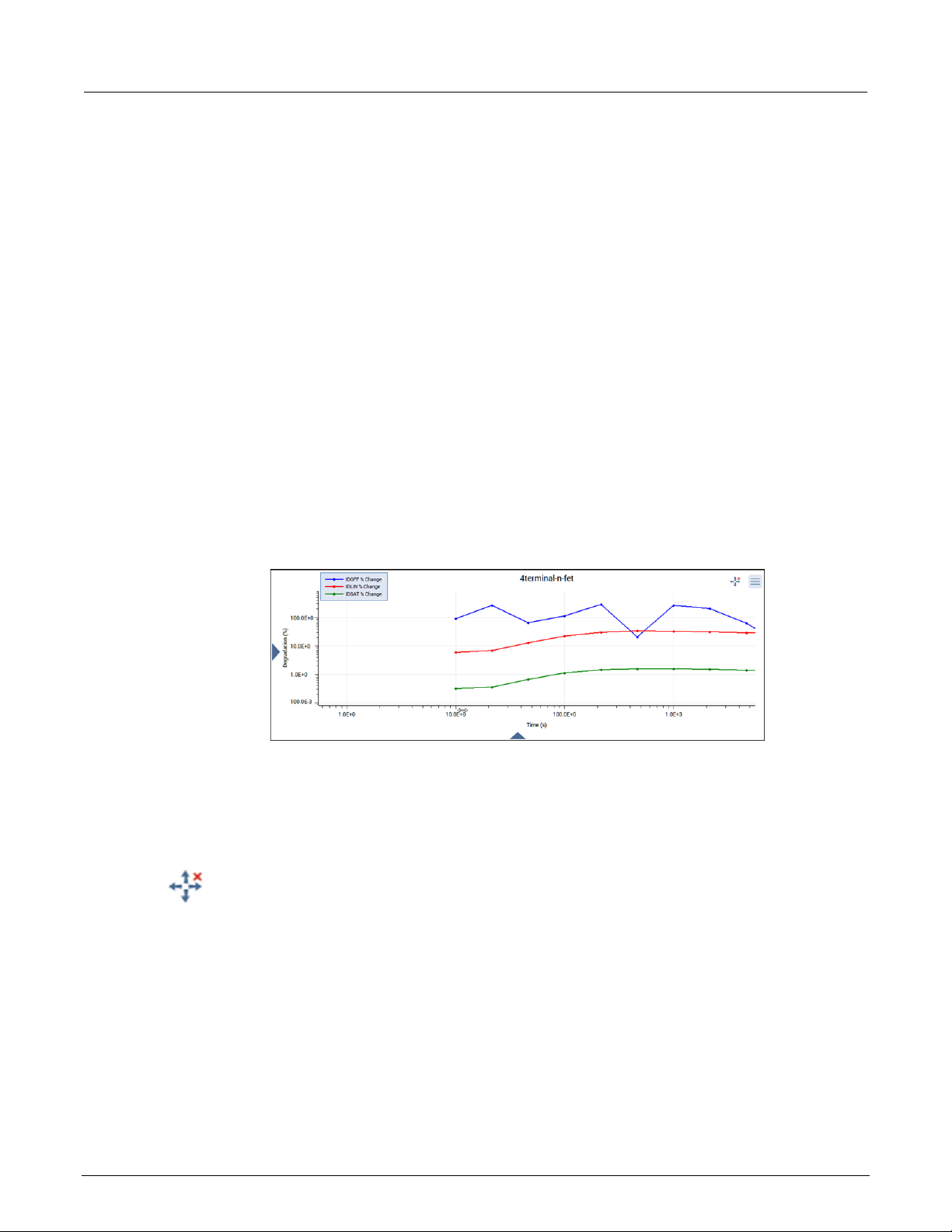
Section
User's Manual
3: Analyze data Model 4200A-SCS Clarius
Zoom, pan, and autoscale
If you are using the touch screen:
• To zoom in on the graph, pinch the area of the graph to view.
• To zoom out, move your fingers apart.
• To return to the full graph view, double-tap the graph.
If you are using a mouse:
• To zoom, select the area on the graph with the left mouse button.
• To return to the full graph view, double-click the graph.
To use the mouse to pan along the axis (left to right on x-axis or up-down on the y-axis):
1. Place the mouse over the axis in the graph. The mouse cursor changes to the scrolling icon.
2. Drag the axis to the new location.
An example of the panned axis is shown in the following figure.
Figure 72: Panning along the x-axis
To pan in all directions:
1. From the Graph Definition Menu, select Start Panning.
2. Drag the graph in any direction.
When panning is active, the following icon is displayed to the left of the Graph Definition Menu:
3-30 4200A-914-01 Rev. D March 2023

Model 4200A
Analyze data
-SCS Clarius User's Manual Section 3:
Select the icon to stop panning. You can also stop panning by selecting another option from the
Graph Definition Menu.
Rescale the graph:
From the Graph Definition Menu, select Autoscale All.
This option automatically scales all graph axes one time. You can use this to reset the graph after
panning or zooming.
When you pan or zoom, Autoscale All is disabled. The minimum and maximum values of each axis
show the values set by zoom.
Save results and graphs
You can save the sheet data and graphs for the entire project or for individual tests or actions.
The sheet data can be saved to the .xls, .xlsx, .csv, or .txt format. The .xls and .xlsx
formats are compatible with the Microsoft
When you save test data to the .xls or .xlsx format, the saved data includes data for all selected
runs and the settings for the runs. If you select the .csv or .txt format, only the data from the most
recent run is saved.
®
Excel® application.
You can save graphs to .jpeg, .bmp, .gif, or .png format.
To export all data from a project, test, or device, use the Data Export tool. Refer to Data Export tool
(on page 4-29) for more informat ion.
To save the information in the Run sheet:
1. Select the project, test, or action.
2. Select Analyze.
3. Select Save Data.
Figure 73: Save Data button
4200A-914-01 Rev. D March 2023 3-31

Section
User's Manual
3: Analyze data Model 4200A-SCS Clarius
The Save Test Data As dialog is displayed, as shown in the following figure.
Figure 74: Save Test Data As dialog
4. In the Sheet field, select the file location and name.
5. From the Sheet File Format list, select the file format.
6. Select Save Sheet.
To save the graph:
1. Select the project, test, or action.
2. Select Analyze.
3. Select Save Data. The Save Test Data As dialog is displayed.
4. In the Graph1 and Graph2 fields, select the file locations and graph names.
5. Select the Graph File Format.
6. Select Save Graph 1 or Save Graph 2.
To save graph and Run sheet information:
1. Select the project, test, or action.
2. Select Analyze.
3. Select Save Data. The Save Test Data As dialog is displayed.
4. If you would like to use the same name for all graphs and sheets, enter the name in the Change
Common Filename field. The file names are changed. No change is made to the file locations.
5. In the Sheet field, select the file location and name.
6. In the Graph1 and Graph2 fields, select the file locations and graph names.
7. Select the Sheet File Format.
8. Select the Graph File Format.
9. Select Save All.
3-32 4200A-914-01 Rev. D March 2023

Tools ...................................................................................... 4-11
In this section:
Customize Clarius .................................................................... 4-1
Add objects to the library .......................................................... 4-1
Project tree display options ...................................................... 4-6
Messages display option .......................................................... 4-6
My Setti ngs .............................................................................. 4-6
Customize Clarius
To customize Clarius, you can:
Section 4
Customizing Cla r i us
• Add your own tests, actions, and projects to the Clarius library.
• Adjust the options in My Settings to set up your working environment and modify project
execution. You can also set up custom GPIB abort settings and view information about Clarius.
• Hide or display the project tree, right pane, and Messages areas of the Clarius window.
Add objects to the library
You can add tests, devices, actions, and projects to the library. The new version of the object
includes the settings you made to the object in the Configure pane. Once an object has been added,
you can use it to create new objects in the project tree.
You cannot add sites and subsites to the library.
When you copy a project, it includes all test definitions, formulas, graph settings, and selected
test runs.
When you add objects to the library, you have the option to enter keywords. You can use these
keywords to label the object with information that you can use to search for the object, such as
including your name or a project name as part of the project.

Section
User's Manual
4: Customizing Clarius Model 4200A-SCS Clarius
Add a test to the library
The following steps provide specifics on how to add a test to the library. You can follow the same
basic procedure to add devices, actions, and projects. The primary difference is the type of object and
which library the object is added to.
When you add a test to the library, the test runs that are selected in the Run History tab of the
Analyze pane are included with the new test. However, notes and aliases that were assigned to the
test runs are not included.
To add a test to the library:
1. In Clarius, set up the test so that it contains the settings you want the new library object to have.
2. Select Analyze.
3. In the Run History tab, select the test runs that you want to include in the new test.
4. Open Select.
5. Drag the test from the project tree to the library. You see a copy of the test and a checkmark, as
shown in the figure below. The test is automatically added to the Tests library, regardless of the
tab that is open. When you drop the test, a confirmation dialog is displayed.
Figure 75: Add a test to the Tests Library
6. Select OK. The Library Information Editor is displayed. Refer to Edit a library object you added
(on page 4-3) to complete the Library Information Editor.
Add a device to the Device Library
You can copy a device from the project tree to the library to create a new device.
To submit a device to a library:
1. In Clarius, choose Select.
2. In the project tree, drag the device into the library. The test is automatically added to the Devices
library, regardless of the tab that is open. A confirmation message is displayed.
3. Select OK. The Library Information Editor dialog is displayed. Refer to
Edit a library object you
added (on page 4-3) to complete the Library Information Editor.
4-2 4200A-914-01 Rev. D March 2023

Model 4200A
Customizing Clarius
-SCS Clarius User's Manual Section 4:
Add an action to the library
The following example provides specifics on how to add an action to the library.
To add an action to the library:
1. In Clarius, set up the action so that it contains the settings you want the new library object
to have.
2. Open the Select pane.
3. Drag the action from the project tree to the library. You see a copy of the action and a checkmark.
The action is automatically added to the Actions library, regardless of the tab that is open. When
you drop the action, a confirmation dialog is displayed.
4. Select OK. The Library Information Editor is displayed. Refer to Edit a library object you added
(on page 4-3).
Add a project to the library
The following example provides specifics on how to add a project to the library.
To add a project to the library:
1. In Clarius, set up the project so that it contains the settings you want the new library object
to have.
2. Open the Select pane.
3. Drag the project from the project tree to the library. You see a copy of the project and a check
mark. The project is added to the Projects library regardless of the tab that is open. When you
drop the project, a confirmation dialog is displayed.
4. Select OK. The Library Information Editor is displayed. Refer to Edit a library object you added
(on page 4-3).
Edit a library object you added
You can edit items that you added to a library. Items that can be edited have Edit, Delete, and Export
options as shown in the following figure.
Figure 76: Edit, Delete, and Exp ort options for a library item
4200A-914-01 Rev. D March 2023 4-3
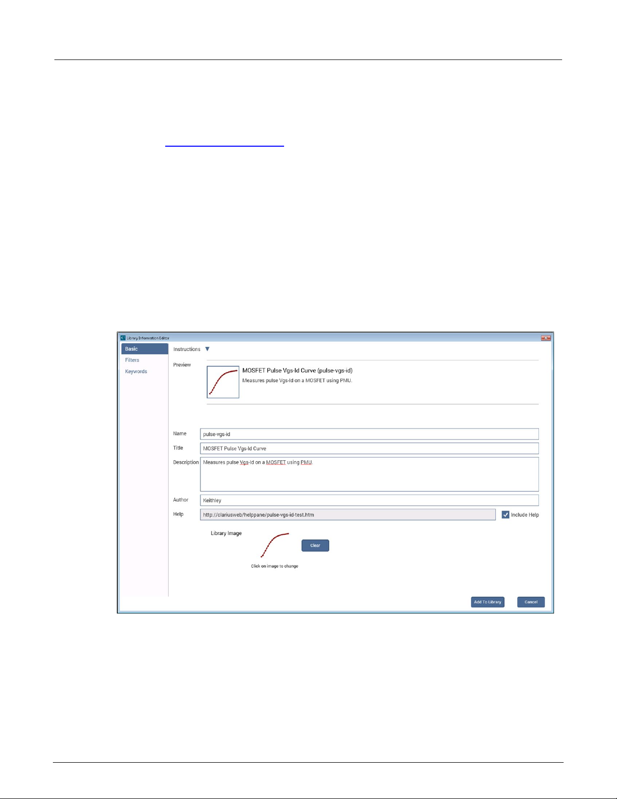
Section
User's Manual
4: Customizing Clarius Model 4200A-SCS Clarius
To edit an item:
1. Select the item in the library.
2. Select Edit.
3. Refer to Edit an object in the library (on page 4-4
Edit an object in the library
The Library Information Editor allows you to change the information for a new library object. You can
change information such as the name, description, graphic, help information, filters, and keywords.
The Library Information Ed i tor is dis pl ayed w he n you drag an object from the proje c t tr ee to the l ibrar y .
For objects that you created, you can also access it using Edit in the library.
As you make changes in the Basic tab, the Preview area displays the changes as they will appear in
the library.
) for the options.
Figure 77: Library Informatio n Editor
4-4 4200A-914-01 Rev. D March 2023

Model 4200A
Customizing Clarius
Displays the changes you make as they will appear in the library.
Type the new name. This is the name that is used in the library and the project tree.
Type the title. This is used in the library.
Project Information Editor.
Only editable when adding an object from the project tree to the library. This is the help
displayed when the item is selected in the library.
Only displayed when you add an item from the project tree to the library. Determines if
can only include or hide it.
The image that is displayed in the library. Select the image to select a different image.
To leave the image area blank, select Clear.
Devices only. The image that is displayed in the project tree. Select the image to choose
-SCS Clarius User's Manual Section 4:
To change information for a library obj ect:
1. In the Basic tab, complete the information as needed. Refer to the following table for the options.
2. Select the Filters tab. These options set the filters that will cause this item to appear in the library
when you select the right-pane filters.
3. Select the filters that help a user find this item in the library.
4. Select the Keywords tab. These options determine what you can type in the library Search field
to locate this item. You can use the Sort By options at the bottom of the lists to change the order
of the entries in the Information Editor. It does not affect the order in the library.
5. Drag a keyword from the left to the right to add a keyword.
6. To remove a keyword, select the keyword and select Delete. This does not remove the keyword
from the Global Keywords list.
7. To add a keyword, select New and type the keyword.
Options in the Information Editor
Preview
Name
Title
Description
Author
Help
Include Help
Library Image
Icon Image
Type a brief description of the item. This is displayed in the library.
Type information that identifies who created this item. This is available only through the
file that is displayed in the right pane when Configure or Analyze is selected. It is also
the existing help is included with the new item. If you want to include the help that was
associated with the original object, select Include Help. Clear Include Help to keep the
help from displaying (the Help pane will be blank). You cannot change the help link; you
Images should be 400x400 pixels in png format. Larger images display, but anything
larger than 400x400 is cut off in the library display.
To re-use an image from an older project, you may need to save the existing bmp image
to png format. You can use a tool such as Microsoft® Paint to convert the image.
a different image. Images should be 80x80 pixels in png format. Larger images display,
but anything larger than 80x80 is cut off in the project tree.
To re-use an image from an older project, you may need to save the existing bmp image
to png format. You can use a tool such as Microsoft® Paint to convert the image.
To leave the image area blank, select Clear.
4200A-914-01 Rev. D March 2023 4-5

Section
User's Manual
4: Customizing Clarius Model 4200A-SCS Clarius
Project tree display options
You can select whether or not Clarius displays the project tree if you need more workspace. To hide
the project tree, select < at the top of the tree. Redisplay the project tree by selecting >.
Messages display option
You can hide the Messages area at the bottom of the Clarius window. To hide Messages, select v. To
display the messages, select ^.
My Settings
The options in My Settings allow you to set environment settings, run settings, GPIB abort, and
logging preferences. You can also view revision and copyright information regarding Clarius.
Specify environment settings
The options in Environment Settings allow you to make system-side settings.
You can set:
• GPIB devices to reset on startup.
• PMUs to allow unsettled measurements.
• The user interface for UTMs to be edited.
• Site tracking for stress testing.
• Save as functionality.
• Where your projects are stored.
• Which project loads at startup.
Reset GPIB devices when Clarius starts
Select this option to reset GPIB devices in the system to their default settings when Clarius starts up.
PMU: Allow unsettled measurements
When this option is selected, all 4225-PMU instrument cards ignore the minimum timing versus
measure range relationship.
This option is only recommended for advanced users. It causes spot mean results to be unsettled,
which may cause a variety of operational issues, such as:
• Inconsistent current measure range-chang ing on the 4 225-PMU or 4225-RPM.
• Lack of proper load-line effect compensation (LLEC) for the PMU.
• Lack of correlation between PMU or PMU and RPM results and SMU results.
For additional information, see “PMU minimum settling times versus current measure range” in the
Model 4200A-SCS Pulse Card (PGU and PMU) User's Manual.
4-6 4200A-914-01 Rev. D March 2023
 Loading...