


Tektronix 4200A-SCS User manual

Model 4200A-SCS
LPT Library
Programming
4200A-LPT-907-01 Rev. C March 2023
tek.com/keithley
*P4200A-LPT-907-01C*
4200A-LPT-907-01C

LPT Library
Model 4200A-SCS
Programming

© 2023, Keithley Instruments
Cleveland, Ohio, U.S.A.
All rights reserved.
Any unauthorized reproduction, photocopy, or use of the information herein, in whole or in part,
without the prior written approval of Keithley Instruments is strictly prohibited.
All Keithley Instruments product names are trademarks or registered trademarks of Keithley
Instruments, LLC. Other brand names are trademarks or registered trademarks of their
respective holders.
Actuate
®
Copyright © 1993-2003 Actuate Corporation.
All Rights Reserve d.
Microsoft, Visual C++, Excel, and Windows are either registered trademarks or trademarks of
Microsoft Corporation in the United States and/or other countries.
Document number: 4200A-LPT-907-01 Rev. C March 2023

Safety precaut ions
The following safety precautio ns should be observed before using this product and any associated ins tr um enta tion . Although
some instruments and accessories would normally be used with nonhazardous voltages, there are situations where hazardous
conditions may be present.
This product is intended for use by personnel who recognize shock hazards and are familiar with the safety precautions required
to avoid possible injury. Read and follow all installation, operation, and maintenance information carefully before using the
product. Refer to the user documentation for complete product specifications.
If the product is used in a manner not specified, the protection provided by the product warranty may be impaired.
The types of product users are:
Responsible body is the individual or group responsible for the use and maintenance of equipment, for ensuring that the
equipment is operated within its specifications and operating limits, and for ensuring that operators are adequately trained.
Operators use the product for its intended function. They must be trained in electrical safety procedures and proper use of the
instrument. They must be protected from electric shock and contact with hazardous live circuits.
Maintenance personnel perform routine procedures on the product to keep it operating properly, for example, setting the line
voltage or replacing consumable materials. Maintenance procedures are described in the user documentation. The procedures
explicitly state if the operator may perform them. Otherwise, they should be performed only by service personnel.
Service personnel are trained to work on live circuits, perform safe installations, and repair products. Only properly trained
service personnel may perform installation and service procedures.
Keithley products are designed for use with electrical signals that are measurement, control, and data I/O connections, with low
transient overvoltages, and must not be directly connected to mains voltage or to voltage sources with high transient
overvoltages. Measurement Category II (as referenced in IEC 60664) connections require protection for high transient
overvoltages often associated with local AC mains connections. Certain Keithley measuring instruments may be connected to
mains. These instruments will be marked as category II or higher.
Unless explicitly allowed in the specifications, operating manual, and instrument labels, do not conn ect any instru ment to mains.
Exercise extreme caution when a shock hazard is present. Lethal voltage may be present on cable connector jacks or test
fixtures. The American National Standards Institute (ANSI) states that a shock hazard exists when voltage levels greater than
30 V RMS, 42.4 V peak, or 60 VDC are present. A good safety practice is to expect that hazardous voltage is present in any
unknown circuit before measuring.
Operators of this product must be protected from electric shock at all times. The responsible body must ensure that operators
are prevented access and/or insulated from every connection point. In some cases, connections must be exposed to potential
human contact. Product operators in these circumstances must be trained to protect themselves from the risk of electric shock. If
the circuit is capable of operating at or above 1000 V, no conductive part of the circuit may be exposed.
Do not connect switching cards directly to unlimited power circuits. They are intended to be used with impedance-limited
sources. NEVER connect switching cards directly to AC mains. When connecting sources to switching cards, install protective
devices to limit fault current and voltage to the card.
Before operating an instrument, ensure that the line cord is connected to a properly-grounded power receptacle. Inspect the
connecting cables, test leads, and jumpers for possible wear, cracks, or breaks before each use.
When installing equipment where access to the main power cord is restricted, such as rack mounting, a separate main input
power disconnect device must be provided in close proximity to the equipment and within easy reach of the operator.
For maximum safety, do not touch the product, test cables, or any other instruments while power is applied to the circuit under
test. ALWAYS remove power from the entire test system and discharge any capacitors before connecting or disconnecting
cables or jumpers, installing or removing switching cards, or making internal changes, such as installing or removing jumpers.
Do not touch any object that could provide a current path to the common side of the circuit under test or power line (earth)
ground. Always make measurements with dry hands while standing on a dry, insulated surface capable of withstanding the
voltage being measured.

For safety, instruments and accessories must be used in accordance with the operating instructions. If the instruments or
accessories are used in a manner not specified in the operating instructions, the protection provided by the equipment may be
impaired.
Do not exceed the maximum signal levels of the instruments and accessories. Maximum signal levels are defined in the
specifications and operating information and shown on the instrument panels, test fixture panels, and switching cards.
When fuses are used in a product, replace with the same type and rating for continued protection against fire hazard.
Chassis connections must only be used as shield connections for measuring circuits, NOT as protective earth (safety ground)
connections.
If you are using a test fixture, keep the lid closed while power is applied to the device under test. Safe operation requires the use
of a lid interlock.
If a screw is present, connect it to protective earth (safety ground) using the wire recommended in the user docume ntat ion.
The symbol on an instrument means caution, risk of hazard. The user must refer to the operating instructions located in the
user documentation in all cases where the symbol is mark ed on the instr u ment .
The symbol on an instrument means warning, risk of electric shock. Use standard safety precautions to avoid personal
contact with these voltages.
The symbol on an instrument shows that the surface may be hot. Avoid personal contact to prevent burns.
The symbol indicates a connection terminal to the equipment frame.
If this symbol is on a product, it indicates that mercury is present in the display lamp. Please note that the lamp must be
properly disposed of according to federal, state, and local laws.
The WARNING heading in the user documentation explains hazards that might result in personal injury or death. Always read
the associated information very carefully before performing the indicated procedure.
The CAUTION heading in the user documentation explains h azard s that coul d dama ge the instrument. Such damage may
invalidate the warranty.
The CAUTION heading with the symbol in the user documentation explains hazards that could result in moderate or minor
injury or damage the instrument. Always read the associated information very carefully before performing the indicated
procedure. Damage to the instrument may invalidate the warranty.
Instrumentation and accessories shall not be connected to humans.
Before performing any maintenance, disconnect the line cord and all test cables.
To maintain protection from electric shock and fire, replacement components in mains circuits — including the power
transformer, test leads, and input jacks — must be purchased from Keithley. Standard fuses with applicable national safety
approvals may be used if the rating and type are the same. The detachable mains power cord provided with the instrument may
only be replaced with a similarly rated power cord. Other components that are not safety-related may be purcha sed from o ther
suppliers as long as they are equivalent to the original component (note that selected parts should be purchased only through
Keithley to maintain accuracy and functionality of the product). If you are unsure about the applicability of a replacement
component, call a Keithley office for information.
Unless otherwise noted in product-specific literature, Keithley instruments are designed to operate indoors only, in the following
environment: Altitude at or below 2,000 m (6,562 ft); temperature 0 °C to 50 °C (32 °F to 122 °F); and pollution degree 1 or 2.
To clean an instrument, use a cloth dampened with deionized water or mild, water-based cleaner. Clean the exterior of the
instrument only. Do not apply cleaner directly to the instrument or allow liquids to enter or spill on the instrument. Products that
consist of a circuit board with no case or chassis (e.g., a data acquisition board for installation into a computer) should never
require cleaning if handled according to instructions. If the board becomes contaminated and operation is affected, the board
should be returned to the factory for proper cleaning/servicing.
Safety precaution revision as of June 2018.

Table of contents
Introduction ............................................................................................................... 1-1
LPT library reference ............................................................................................................ 1-1
Lists of LPT library commands ............................................................................................. 1-2
General operation commands ................................................................................................... 1-2
Math operation commands ........................................................................................................ 1-4
SMU commands ........................................................................................................................ 1-4
PGU (pulse only) and PMU (pulse and measure) commands ................................................... 1-5
CVU commands ........................................................................................................................ 1-7
Switch commands ..................................................................................................................... 1-8
LPT Library Status and Error codes ..................................................................................... 1-8
Customized error texts .............................................................................................................. 1-9
Code status or error titles ........................................................................................................ 1-10
Large number reported readings and explanations ................................................................. 1-15
LPT library and Clarius interaction when using UTMs ....................................................... 1-16
LPT commands for general operations ................................................................... 2-1
LPT commands for general operations ................................................................................ 2-2
clrscn ......................................................................................................................................... 2-2
clrtrg .......................................................................................................................................... 2-3
delay ......................................................................................................................................... 2-5
devint ........................................................................................................................................ 2-6
disable ....................................................................................................................................... 2-8
enable ....................................................................................................................................... 2-8
execut ....................................................................................................................................... 2-8
getinstattr .................................................................................................................................. 2-9
getinstid ................................................................................................................................... 2-10
getinstname............................................................................................................................. 2-10
GetKiteCycle ........................................................................................................................... 2-11
GetKiteDevice ......................................................................................................................... 2-11
GetKiteSite .............................................................................................................................. 2-11
GetKiteSubsite ........................................................................................................................ 2-12
GetKiteTest ............................................................................................................................. 2-12
getlpterr ................................................................................................................................... 2-13
imeast ..................................................................................................................................... 2-13
inshld ....................................................................................................................................... 2-13
kibcmd ..................................................................................................................................... 2-14
kibdefclr ................................................................................................................................... 2-15
kibdefdelete ............................................................................................................................. 2-16
kibdefint ................................................................................................................................... 2-16
kibrcv ....................................................................................................................................... 2-17
kibsnd ...................................................................................................................................... 2-18
kibspl ....................................................................................................................................... 2-19
kibsplw .................................................................................................................................... 2-20
kspcfg ...................................................................................................................................... 2-20
kspdefclr .................................................................................................................................. 2-21
kspdefdelete ............................................................................................................................ 2-22
kspdefint .................................................................................................................................. 2-22
ksprcv ...................................................................................................................................... 2-23
kspsnd ..................................................................................................................................... 2-23
PostDataDouble ...................................................................................................................... 2-24
PostDataInt ............................................................................................................................. 2-25
PostDataString ........................................................................................................................ 2-26
rdelay ...................................................................................................................................... 2-26

Table of contents Model 4200A-SCS LPT Library Programming
rtfary ........................................................................................................................................ 2-27
savgX ...................................................................................................................................... 2-27
scnmeas .................................................................................................................................. 2-29
searchX ................................................................................................................................... 2-29
setmode .................................................................................................................................. 2-32
sintgX ...................................................................................................................................... 2-34
smeasX ................................................................................................................................... 2-35
trigcomp .................................................................................................................................. 2-36
trigXg, trigXl............................................................................................................................. 2-37
tstdsl ........................................................................................................................................ 2-40
tstsel ........................................................................................................................................ 2-40
LPT commands for math operations ....................................................................... 3-1
LPT commands for math operations .................................................................................... 3-1
kfpabs ....................................................................................................................................... 3-1
kfpadd ....................................................................................................................................... 3-2
kfpdiv ......................................................................................................................................... 3-2
kfpexp ....................................................................................................................................... 3-3
kfplog ........................................................................................................................................ 3-4
kfpmul ....................................................................................................................................... 3-4
kfpneg ....................................................................................................................................... 3-5
kfppwr ....................................................................................................................................... 3-6
kfpsqrt ....................................................................................................................................... 3-7
kfpsub ....................................................................................................................................... 3-8
LPT commands for SMUs ......................................................................................... 4-1
LPT commands for SMUs .................................................................................................... 4-1
adelay ....................................................................................................................................... 4-1
asweepX ................................................................................................................................... 4-2
avgX .......................................................................................................................................... 4-4
bmeasX ..................................................................................................................................... 4-5
bsweepX ................................................................................................................................... 4-7
devclr ........................................................................................................................................ 4-9
devint ........................................................................................................................................ 4-9
forceX ...................................................................................................................................... 4-11
getstatus.................................................................................................................................. 4-12
intgX ........................................................................................................................................ 4-14
limitX ....................................................................................................................................... 4-16
lorangeX .................................................................................................................................. 4-17
measX ..................................................................................................................................... 4-18
mpulse .................................................................................................................................... 4-20
pulseX ..................................................................................................................................... 4-21
rangeX .................................................................................................................................... 4-23
rtfary ........................................................................................................................................ 4-25
segment_sweepX_list ............................................................................................................. 4-26
setauto .................................................................................................................................... 4-27
ssmeasx .................................................................................................................................. 4-28
sweepX ................................................................................................................................... 4-29
LPT commands for CVUs ......................................................................................... 5-1
LPT commands for the CVUs .............................................................................................. 5-1
adelay ....................................................................................................................................... 5-2
asweepv .................................................................................................................................... 5-3
bsweepX ................................................................................................................................... 5-4
cvu_custom_cable_comp .......................................................................................................... 5-6
devclr ........................................................................................................................................ 5-6

Model 4200A-SCS LPT Library Programming Table of contents
devint ........................................................................................................................................ 5-7
dsweepf ..................................................................................................................................... 5-8
dsweepv .................................................................................................................................. 5-10
forcev ...................................................................................................................................... 5-11
getstatus.................................................................................................................................. 5-12
measf ...................................................................................................................................... 5-13
meass ..................................................................................................................................... 5-14
meast ...................................................................................................................................... 5-15
measv ..................................................................................................................................... 5-15
measz ..................................................................................................................................... 5-16
rangei ...................................................................................................................................... 5-17
rtfary ........................................................................................................................................ 5-18
setauto .................................................................................................................................... 5-19
setfreq ..................................................................................................................................... 5-19
setlevel .................................................................................................................................... 5-20
setmode (4210-CVU or 4215-CVU) ........................................................................................ 5-21
smeasf .................................................................................................................................... 5-23
smeasfRT ................................................................................................................................ 5-23
smeass .................................................................................................................................... 5-24
smeast .................................................................................................................................... 5-25
smeastRT ................................................................................................................................ 5-26
smeasv .................................................................................................................................... 5-26
smeasvRT ............................................................................................................................... 5-27
smeasz .................................................................................................................................... 5-28
smeaszRT ............................................................................................................................... 5-29
sweepf ..................................................................................................................................... 5-30
sweepf_log .............................................................................................................................. 5-32
sweepv .................................................................................................................................... 5-33
Programming examples ..................................................................................................... 5-34
Programming example #1 ....................................................................................................... 5-34
Programming example #2 ....................................................................................................... 5-35
Programming example #3 ....................................................................................................... 5-36
Programming example #4 ....................................................................................................... 5-37
Programming example #5 ....................................................................................................... 5-38
LPT commands for PGUs and PMUs ....................................................................... 6-1
LPT commands for PGUs and PMUs .................................................................................. 6-1
arb_array ................................................................................................................................... 6-3
arb_file ...................................................................................................................................... 6-4
dev_abort .................................................................................................................................. 6-4
devclr ........................................................................................................................................ 6-6
devint ........................................................................................................................................ 6-6
getstatus.................................................................................................................................... 6-8
pg2_init ................................................................................................................................... 6-10
pmu_offset_current_comp....................................................................................................... 6-11
PostDataDoubleBuffer ............................................................................................................ 6-11
pulse_burst_count ................................................................................................................... 6-14
pulse_chan_status .................................................................................................................. 6-15
pulse_conncomp ..................................................................................................................... 6-16
pulse_current_limit .................................................................................................................. 6-17
pulse_dc_output ...................................................................................................................... 6-18
pulse_delay ............................................................................................................................. 6-19
pulse_exec .............................................................................................................................. 6-20
pulse_exec_status .................................................................................................................. 6-21
pulse_fall ................................................................................................................................. 6-22
pulse_fetch .............................................................................................................................. 6-24
pulse_float ............................................................................................................................... 6-28
pulse_halt ................................................................................................................................ 6-29
pulse_init ................................................................................................................................. 6-30

Table of contents Model 4200A-SCS LPT Library Programming
pulse_limits ............................................................................................................................. 6-31
pulse_load ............................................................................................................................... 6-32
pulse_meas_sm ...................................................................................................................... 6-33
pulse_meas_timing ................................................................................................................. 6-34
pulse_meas_wfm .................................................................................................................... 6-36
pulse_measrt ........................................................................................................................... 6-37
pulse_output............................................................................................................................ 6-38
pulse_output_mode ................................................................................................................. 6-39
pulse_period............................................................................................................................ 6-40
pulse_range ............................................................................................................................ 6-41
pulse_ranges ........................................................................................................................... 6-42
pulse_remove .......................................................................................................................... 6-44
pulse_rise ................................................................................................................................ 6-45
pulse_sample_rate .................................................................................................................. 6-46
pulse_source_timing ............................................................................................................... 6-47
pulse_ssrc ............................................................................................................................... 6-48
pulse_step_linear .................................................................................................................... 6-50
pulse_sweep_linear ................................................................................................................ 6-53
pulse_train............................................................................................................................... 6-56
pulse_trig................................................................................................................................. 6-57
pulse_trig_output ..................................................................................................................... 6-58
pulse_trig_polarity ................................................................................................................... 6-59
pulse_trig_source .................................................................................................................... 6-60
pulse_vhigh ............................................................................................................................. 6-62
pulse_vlow .............................................................................................................................. 6-63
pulse_width ............................................................................................................................. 6-65
rpm_config .............................................................................................................................. 6-66
seg_arb_define ....................................................................................................................... 6-67
seg_arb_file............................................................................................................................. 6-69
seg_arb_sequence .................................................................................................................. 6-70
seg_arb_waveform .................................................................................................................. 6-73
setmode (4225-PMU) .............................................................................................................. 6-74
LPT commands for switching .................................................................................. 7-1
LPT commands for switching ............................................................................................... 7-1
addcon ...................................................................................................................................... 7-1
clrcon ........................................................................................................................................ 7-2
conpin ....................................................................................................................................... 7-2
conpth ....................................................................................................................................... 7-3
cviv_config ................................................................................................................................ 7-4
cviv_display_config ................................................................................................................... 7-5
cviv_display_power ................................................................................................................... 7-6
delcon ....................................................................................................................................... 7-6
devint ........................................................................................................................................ 7-7

LPT library and Clarius interaction when using UTMs ............1-16
In this section:
LPT library reference ................................................................1-1
Lists of LPT library commands ..................................................1-2
LPT Library Status and Error codes ..........................................1-8
LPT library reference
The Keithley Instruments Linear Parametric Test Library (LPT library) is a high-speed data acquisition
and instrument control software library. It is the programmer’s lowest level of command interface to
the system instrumentation. You can use the library commands to configure the relay matrix and
instrumentation for parametric tests.
Section 1
Introduction
This section lists the commands included in the LPT library and describes how to use them. The
descriptions include:
• A brief description of the command.
• Usage, which shows how the command should be organized and descriptions of each parameter.
The parameters that you need to supply are shown in italics. For example, for the command
int delay(long n);, replace n with the duration of the delay.
• Detailed information about the command.
• Examples that show a typical use of the command in a test sequence.
The following conventions are used when explaining the commands:
• All LPT library commands are case-sensitive and must be entered as lower case when writing
program code.
• Period strings (...) indicate additional arguments or commands that can be added.
• Periods ( . ) indicate data not shown in an example because it is not necessary to help explain
the specific command.

Section 1: Introduction Model 4200A-SCS LPT Library Programming
i
Current
Amperes
t
Time
Seconds
v
Voltage
Volts
f
Frequency
Hertz
clrscn (on page 2-2)
Clears the measurement scan tables associ at ed with a swee p.
Clears the user-selected voltage or current level that is used to set trigger
once with different levels in a single test sequence.
delay (on page 2-5)
Provides a user-programmable delay in a test sequence.
devint (on page 2-6)
Resets all active instruments in the system to their default states.
disable (on page 2-8)
Stops the timer and sets the time value to zero (0).
enable (on page 2-8)
Provides correlation of real time to measurements of voltage, current,
conductance, and capacitance.
execut (on page 2-8)
Causes the system to wait for the preceding test sequence to be executed.
getinstattr (on page 2-9)
Returns configured instrument attributes.
getinstid (on page 2-10)
Returns the instrument identifier (ID) from the instrument name string.
getinstname (on page 2-10)
Returns the instrument name string from the instrument identifier (ID).
GetKiteCycle (on page 2-11)
Returns the present Clarius cycle number.
GetKiteDevice (on page 2-11)
Returns the device that Clarius is presently testing.
• A capital letter X in a command name indicates that you must select from a list of replacement
suffixes. For example, in forceX, replace the X w ith e ither a v for voltage or i for current. The
following is a table of possible suffixes, the parameter each represents, and the units used
throughout the LPT library for that parameter.
Suffix Parameter Unit
Lists of LPT library commands
These topics list the LPT library commands that are available in the 4200A-SCS. A brief description
and links to full descriptions of each command are provided.
The LPT library commands are grouped as follows:
• General operation commands (on page 1-2)
• Math operation commands (on page 1-4)
• SMU commands (on page 1-4)
• PGU (pulse only) and PMU (pulse and measure) commands (on page 1-5)
• CVU commands (on page 1-7)
• Switch commands (on page 1-8)
General operation commands
General operation commands include commands to control timing, execution, communications, and
test status.
Command Description
clrtrg (on page 2-3)
points. This permits the use of the trigXl or trigXg command more than
1-2 4200A-LPT-907-01 Rev. C March 2023
Model 4200A-SCS LPT Library Programming Section 1: Introduction
GetKiteSite (on page 2-11)
Returns the site number for the site that Clarius is presently testing.
GetKiteSubsite (on page 2-12)
Returns the subsite number for the site that Clarius is presently testing.
GetKiteTest (on page 2-12)
Returns the test that Clarius is presently testing.
getlpterr (on page 2-13)
Returns the first LPT library error since the last devint command.
imeast (on page 2-13)
Forces a reading of the timer and returns the result.
inshld (on page 2-13)
Provided for compatibility with Model S400 LPT library.
kibcmd (on page 2-14)
Enables universal, addressed, and unaddressed GPIB bus commands to be
sent through the GPIB interface.
kibdefclr (on page 2-15)
Defines the device-dependent command sent to an instrument connected to
the GPIB interface.
kibdefdelete (on page 2-16)
Deletes all command definitions previously made with the kibdefclr
device initialize) commands.
kibdefint (on page 2-16)
Defines a device-dependent command sen t to an instrument connected to the
GPIB interface.
kibrcv (on page 2-17)
Reads a device-dependent string from an instrument connected to the GPIB
interface.
kibsnd (on page 2-18)
Sends a device-dependent command to an instrument connected to the GPIB
interface.
kibspl (on page 2-19)
Serial polls an instrument connected to the GPIB inter f ac e.
kibsplw (on page 2-20)
Synchronously serial polls an instrument connected to the GPIB interface.
kspcfg (on page 2-20)
Configures and allocates a serial port for RS-232 communications.
kspdefclr (on page 2-21)
Defines a device-dependent character string sent to an instrument connected
to a serial port.
kspdefdelete (on page 2-22)
Deletes all command definitions previously made with the kspdefclr
Device Initialize) commands.
kspdefint (on page 2-22)
Defines a device-dependent character string sent to an instrument connected
to a serial port.
ksprcv (on page 2-23)
Reads data from an instrument connected to a serial port.
kspsnd (on page 2-23)
Sends a device-dependent command to an instrument attached to a RS-232
serial port.
PostDataDouble (on
page 2-24)
Posts double-precision floa ting -point data from memory into the Clarius
Analyze sheet.
PostDataDoubleBuffer (on
page 6-11)
Posts PMU data retrieved from the buffer into the Clarius Analyze sheet (large
data sets).
PostDataInt (on page 2-25)
Posts an integer-type point from memory to the Clarius Analyze sheet in the
user test module and plots it on the graph.
PostDataString (on page 2-26)
Transfers a string from memory into the Clarius Analyze sheet in the user test
module and plots it on the graph.
rdelay (on page 2-26)
Sets a user-programmable delay.
rtfary (on page 2-27)
Returns the force array determined by the instrument action.
savgX (on page 2-27)
Makes an averaging measurement for every point in a sweep.
scnmeas (on page 2-29)
Makes a single measurement on multiple instruments at the same time.
searchX (on page 2-29)
Used to determine the voltage or current required to get a current or voltage.
setmode (on page 2-32)
Sets instrument-specific operating mode parameters.
sintgX (on page 2-34)
Makes an integrated measurement for every point in a sweep.
smeasX (on page 2-35)
Allows a number of measurements to be made by a specified instrument
are stored in the
defined array.
Command Description
(Keithley GPIB define device clear) and kibdefint (Keithley GPIB define
(Keithley Serial Define Device Clear) and kspdefint (Keithley Serial Define
during a sweepX command. The results of the measurements
4200A-LPT-907-01 Rev. C March 2023 1-3
Section 1: Introduction Model 4200A-SCS LPT Library Programming
trigcomp (on page 2-36)
Causes a trigger when an instrument goes in or out of compliance.
trigXg, trigXl (on page 2-37)
Monitors for a predetermined level of voltage, current, or time.
tstdsl (on page 2-40)
Deselects a test station.
tstsel (on page 2-40)
Enables or disables a test station.
value that is returned to a specified variable.
kfpadd (on page 3-2)
Adds two real numbers and stores the result in a specified variable.
kfpdiv (on page 3-2)
Divides two real numbers and stores the result in a specified variable.
kfpexp (on page 3-3)
Supplies the base of natural logarithms (e) raised to a specified power and stores
the result as a variable.
kfplog (on page 3-4)
Returns the natural logarithm of a real number to the specified variable.
kfpmul (on page 3-4)
Multiplies two real numbers and stores the result as a specified variable.
kfpneg (on page 3-5)
Changes the sign of a value and stores the result as a specified variable.
kfppwr (on page 3-6)
Raises a real number to a specified power and assigns the result to a
specified variable.
kfpsqrt (on page 3-7)
Performs a square root operation on a real number and returns the result to the
specified variable.
kfpsub (on page 3-8)
Subtracts two real numbers and stores their difference in a specified variable.
adelay (on page 4-1)
Specifies an array of delay points to use with asweepX command calls.
Generates a waveform based on a user-defined forcing array (logarithmic sweep or
other custom forcing commands).
avgX (on page 4-4)
Makes a series of measurements and averages the results.
bmeasX (on page 4-5)
Makes a series of readings as quickly as possible. This measurement mode allows
measurement instrument).
bsweepX (on page 4-7)
Supplies a series of ascending or descending voltages or currents and shuts down
the source when a trigger condition is encountered.
devclr (on page 4-9)
Sets all sources to a zero state.
devint (on page 2-6)
Resets all active instruments in the system to their default states.
forceX (on page 4-11)
Programs a sourcing instrument to generate a voltage or current at a specific level.
getstatus (on page 4-12)
Returns the operating state of a specified instrument.
intgX (on page 4-14)
Performs voltage or current measurements averaged over a user-defined period
(usually one ac line cycle).
limitX (on page 4-16)
Allows the programmer to specify a current or voltage limit other than the default
limit of the instrument.
lorangeX (on page 4-17)
Defines the bottom autorange limit.
measX (on page 4-18)
Allows the measurement of voltage, curre nt, or time.
mpulse (on page 4-20)
Uses a source-measure unit (SMU) to force a voltage pulse and measure both the
voltage and current for exact device loading.
Command Description
Math operation commands
Command Description
kfpabs (on page 3-1)
Takes a user-specified positive or negative value and converts it into a positive
SMU commands
Command Description
asweepX (on page 4-2)
for waveform capture and analysis (within the resolution of the
1-4 4200A-LPT-907-01 Rev. C March 2023
Model 4200A-SCS LPT Library Programming Section 1: Introduction
adelay (on page 4-1)
Specifies an array of delay points to use with asweepX command calls.
pulseX (on page 4-21)
Directs a SMU to force a voltage or current at a specific level for a predetermined
length of time.
rangeX (on page 4-23)
Selects a range and prevents the selected instrument from autoranging.
rtfary (on page 2-27)
Returns the array of force values used during the subsequent voltage or frequency
sweep.
segment_sweepX_list
(on page 4-26)
Creates and returns up to a 4-segment linear sweep force table based on userdefined start, stop, and step values.
setauto (on page 4-27)
Re-enables autoranging and cancels any previous rangeX c ommand f or the
specified instrument.
ssmeasX (on page 4-28)
Makes a series of readings until the change (delta) between readings is within a
specified percentage.
sweep consists of a sequence of steps, each with a user-specified duration.
arb_array (on page 6-3)
Used to define a full-arb waveform and name the file.
arb_file (on page 6-4)
Loads a waveform from an existing full-arb waveform file.
dev_abort (on page 6-4)
PGU, PMU. Programmatically ends (aborts) a test from within the user
pulse_exec
devclr (on page 4-9)
Sets all sources to a zero state.
devint (on page 2-6)
Resets all active instruments in the system to their default states.
getstatus (on page 4-12)
Returns the operating state of a specified instrument.
pg2_init (on page 6-10)
Resets the pulse card to the specified pulse mode (standard, full arb, or
Segment Arb) and its default conditions.
pmu_offset_current_comp (on
page 6-11)
PMU. Collects offsets current constants from the 4225-PMU for offset
compensation measurements.
PostDataDoubleBuffer (on
page 6-11)
PMU. Posts PMU data retrieved from the buffer into the Clarius Analyze
sheet (large data sets).
pulse_burst_count (on page 6-14)
For the burst mode, this command sets the number of pulses to output
during a burst sequence.
pulse_chan_status (on pag e 6-15)
PMU. Used to determine how many readings are stored in the data buffer.
pulse_conncomp (on page 6-16)
PMU. Enables or disables connection compen sat ion.
pulse_current_limit (on pag e 6-17)
Channel number of the pulse card: 1 or 2
pulse_dc_output (on page 6-18)
Selects the dc output mode and sets the voltage level.
pulse_delay (on page 6-19)
Sets the delay time from the trigger to when the pulse output starts.
pulse_exec (on page 6-20)
PGU, PMU. Used to validate the test configuration and start test execution.
pulse_exec_status (on page 6-21)
PGU, PMU. Used to determine if a test is running or completed.
pulse_fall (on page 6-22)
Sets the fall transition time for the pulse output.
pulse_fetch (on page 6-24)
PMU. Retrieves enabled test data and temporarily stores it in the data
buffer.
Command Description
sweepX (on page 4-29) Generates a ramp consisting of ascending or descending voltages or currents. The
PGU (pulse only) and PMU (pulse and measure) commands
In the LPT commands, the pulse-only module (4220-PGU) is referred to as VPU1, VPU2, and so on.
The pulse-measure module (4225-PMU) is referred to as PMU1, PMU 2, and so on. The 4210-CVU or
4215-CVU is referred to as CVU1, CVU2, and so on.
Note that the 4225-PMU and 4220-PGU support the PG2 commands.
Command Description
module that was started with the
command.
4200A-LPT-907-01 Rev. C March 2023 1-5

Section 1: Introduction Model 4200A-SCS LPT Library Programming
pulse_float (on page 6-28)
PMU. Sets the state of the floating relay for the given pulse instrument
pulse_halt (on page 6-29)
Stops all pulse output from the pulse card.
pulse_init (on page 6-30)
Resets the pulse card to the default settings for the pulse mode that is
presently selected.
pulse_limits (on page 6-31)
PMU. Sets measured voltage and current thre sh old s at the DUT and sets
the power threshold for each channel.
pulse_load (on page 6-32)
Sets the output impedance for the load (DUT).
pulse_meas_sm (on page 6-33)
PMU. Configures spot mean measurement s.
pulse_meas_timing (on
page 6-34)
PMU. Sets the measurement windows.
pulse_meas_wfm (on page 6-36)
PMU. Configures waveform measurements.
pulse_measrt (on page 6-37)
PMU. Returns pulse source and measure data in pseudo real time.
pulse_output (on page 6-38)
Sets the pulse output of a pulse card channel on or off.
pulse_output_mode (on
page 6-39)
pulse_period (on page 6-40)
Sets the period for pulse output.
pulse_range (on page 6-41)
Sets a pulse card channel for low voltage (fast speed) or high voltage
(slow speed).
PGU, PMU. Sets the voltage pulse range and voltage/current
measure ranges.
pulse_remove (on page 6-44)
PGU, PMU. Removes a pulse channel from the test.
pulse_rise (on page 6-45)
Sets the rise transition time for the pulse card pulse output.
pulse_sample_rate (on
page 6-46)
PMU. Sets the measurement sample rate.
pulse_source_timing (on
page 6-47)
PGU, PMU. Sets the pulse period, pulse width, rise time, fall time, and
delay time.
pulse_ssrc (on page 6-48)
Controls the high-endurance output relay (HEOR) for each output channel
of the PGU.
pulse_step_linear (on page 6-50)
PGU, PMU. Configures the pulse stepping type.
pulse_sweep_linear (on
page 6-53)
PGU, PMU. Configures the pulse sweeping type.
pulse_train (on page 6-56)
PGU, PMU. Configures the pulse card to output a pulse train using fixed
voltage values.
Selects the trigger mode (continuous, burst, or trigger burst) and initiates
the start of pulse output or arms the pulse card.
pulse_trig_output (on page 6-58)
Sets the output trigger on or off.
pulse_trig_polarity (on page 6-59)
Sets the polarity (positive or negative) of the pulse card output trigger.
pulse_trig_source (on page 6-60)
Sets the trigger source.
pulse_vhigh (on page 6-62)
Sets the pulse voltage high level.
pulse_vlow (on page 6-63)
Sets the pulse voltage low value.
pulse_width (on page 6-65)
Sets the pulse width for pulse output.
rpm_config (on page 6-66)
PMU with 4225-RPM. Sends switching commands to the 4225-RPM.
seg_arb_define (on page 6-67)
Defines the parameters for a Segment Arb® waveform.
seg_arb_file (on page 6-69)
Used to load a waveform from an existing Segment Arb® waveform file.
seg_arb_sequence (on
page 6-70)
PGU, PMU. Defines the parameters for a Segment Arb waveform
pulse-measure sequence.
seg_arb_waveform (on
page 6-73)
PGU, PMU. Creates a voltage segment waveform.
setmode (on page 6-74)
PMU. Sets the number of iterations for load-line effect compensation
(LLEC) for the PMU. Also enables or disables offset current compensation.
Command Description
Sets the pulse output mode of a pulse card channel.
pulse_ranges (on page 6-42)
pulse_trig (on page 6-57)
1-6 4200A-LPT-907-01 Rev. C March 2023

Model 4200A-SCS LPT Library Programming Section 1: Introduction
adelay (on page 4-1)
Specifies an array of delay points to use with asweepX command calls.
asweepv (on page 5-3)
Does a dc voltage sweep using an array of voltage values.
bsweepX (on page 4-7)
Supplies a series of ascending or descending voltages or currents and shuts
down the source when a trigger condition is encountered.
cvu_custom_cable_comp (on
page 5-6)
Determines the delays needed to accommodate custom cable lengths.
devclr (on page 4-9)
Sets all sources to a zero state.
devint (on page 2-6)
Resets all active instruments in the system to their default states.
dsweepf (on page 5-8)
Performs a dual frequency sweep.
dsweepv (on page 5-10)
Performs a dual linear staircase voltage sweep.
forcev (on page 5-11)
Sets the dc bias voltage level.
getstatus (on page 5-12)
Returns parameters that describe the state of the 4210-CVU or 4215-CVU.
measf (on page 5-13)
Returns the frequency sourced during a single measurement.
meass (on page 5-14)
Returns the status referenced to a single measure me nt.
meast (on page 5-15)
Returns a timestamp referenced to a measurement or a system timer.
measv (on page 5-15)
Returns the dc bias voltage sourced during a single measurement.
measz (on page 5-16)
Makes an impedance measurement.
rangei (on page 5-17)
Selects an impedance measurement range.
rtfary (on page 4-25)
Returns the array of force values used during the subsequent voltage or
frequency sweep.
setauto (on page 5-19)
Selects the automatic measurement range.
setfreq (on page 5-19)
Sets the frequency for the ac drive.
setlevel (on page 5-20)
Sets the voltage level of the ac drive.
setmode (on page 5-21)
Sets operating modes specific to the 4210-CVU or 4215-CVU.
smeasf (on page 5-23)
Returns the frequencies used for a sweep.
smeasfRT (on page 5-23)
Returns the sourced frequencies (in real time) for a sweep.
smeass (on page 5-24)
Returns the measurement status values for every point in a sweep.
smeast (on page 5-25)
Returns timestamps referenced to sweep measurements or a system timer.
smeastRT (on page 5-26)
Returns timestamps (in real time) referenced to sweep measurements or a
system timer.
smeasv (on page 5-26)
Returns the dc bias voltages used for a sweep.
smeasvRT (on page 5-27)
Returns the sourced dc bias voltages (in real time) for a sweep.
smeasz (on page 5-28)
Performs impedance measurements for a sweep.
smeaszRT (on page 5-29)
Makes and returns impedance measurements for a voltage or frequency sweep
in real time.
sweepf (on page 5-30)
Performs a frequency sweep.
sweepf_log (on page 5-32)
Performs a logarithmic frequency sweep using a 4215-CVU instrument. This is
not available for the 4210-CVU.
sweepv (on page 5-33)
Performs a linear staircase dc voltage sweep.
CVU commands
Command Description
4200A-LPT-907-01 Rev. C March 2023 1-7

Section 1: Introduction Model 4200A-SCS LPT Library Programming
addcon (on page 7-1)
Adds connections without clearing existing connections.
Opens or de-energizes all device under test (DUT) pins and instrument matrix
relays, disconnecting all crosspoint connections.
conpin (on page 7-2)
Connects pins and instruments.
conpth (on page 7-3)
Connects pins and instruments using a specific pathway.
cviv_config (on page 7-4)
Sends switching commands to the 4200A-CVIV Multi-Switch.
page 7-5)
cviv_display_power (on
page 7-6)
Sets the display state of the LCD display on the 4200A-CVIV.
Switch commands
Command Description
clrcon (on page 7-2)
cviv_display_config (on
delcon (on page 7-6) Removes specific matrix connecti ons .
devint (on page 2-6) Resets all active instruments in the system to their default states.
Configures the LCD display on the 4200A-CVIV Multi-Switch.
LPT Library Status and Error codes
Error codes are displayed whenever an invalid parameter or configuration occurs. The messages
associated with the error codes describe the error condition to help the user module programmer or
user determine how to address the error. Once an error occurs, the response of the user module to
the error depends on how the user module is programmed. If a user module does not have any error
handling, an initial error could cause additional errors on following LPT commands.
Library status and error codes are reported in Clarius in the message area.
Codes with positive values are statuses or updates. Codes with negative values are errors and
warnings.
Each error code number is associated with a brief text explanation. However, many of the error texts
are customized with specific information, such as a particular SMU or ID number. See
error texts (on page 1-9) for an explanation of the type of customized data.
Customized
In addition to error codes, some conditions may prevent a valid measurement condition. In these
cases, the reported measurement value reports a condition. This is usually a large number with an
22
exponent of 10
or 1023. See Large number reported readings and explanations (on page 1-15) for
the conditions associated with these large numbers.
1-8 4200A-LPT-907-01 Rev. C March 2023

Model 4200A-SCS LPT Library Programming Section 1: Introduction
%d
Signed decimal number; may be a parameter index or GPIB addr e ss
%g
Double value
%i
Signed decimal number
%s
String, such as "SMU1" or other test resource
%u
Unsigned integer
%04x
Hexadecimal number, 4 places
%08x
Hexadecimal number, 8 places
Figure 1: LPT error codes in the Clarius message areas
Customized error texts
Key Explanation
4200A-LPT-907-01 Rev. C March 2023 1-9

Section 1: Introduction Model 4200A-SCS LPT Library Programming
2802 to 2807
RPM: Invalid Configuration Requested
2801
RPM: Returned ID Error Response
2800
RPM: Command Response Timeout
2702
PMU: Temperature Within Normal Range
2701
PMU: High Temperature Limit Exceeded
1905
PMU: Measure Program Error
1904
PMU: Source Program Error
1902
PMU: Transmission to analog from digital error
1901
PMU: Handshake from analog to digital error
1900
PMU: DA Communication Timeout
400 to 402
PMU: Invalid Attributes in SW Command
100
LPTLib is executing function %s on instrument ID %d.
55
%s is no longer in thermal shutdown.
54
%s VXIBus device busy (command ID %04x). Timed out after %g seconds.
53
%s VXIbus transaction recovered after %u timeouts.
52
%s VXIbus transaction (command ID %04x) timed out after %g seconds.
51
Interlock reset.
50
Interlock tripped.
40
%s
24
Config %d-%d complet e for %s (%d).
23
Config %d-%d starting for %s (%d).
22
Binding %s (%d) to driver %s.
21
Loading driver %s.
20
Preloading model code %08x (%s).
15
Executor started.
14
%s channel closed.
13
%s channel starting.
12
TAPI services shutting down.
11
Starting TAPI services.
9
System configuration complete.
8
System configuration starting.
4
System initialization complete.
1
The call was successful (no error).
0
The call was successful (no error).
−4
Too many instruments in configuration file %s.
−5
Memory allocation failure.
−6
Memory allocation error during configuration with configuration file %s.
−20
Command not executed because a previous error was encountered.
−21
Tester is in a fatal error state.
−22
Fatal condition detected while in testi ng state .
−23
Execution aborted by user.
−24
Too many arguments.
−25
%s is unavailable because it is in use by another test station.
−40
%s.
Code status or error titles
Code Status or error titles
1-10 4200A-LPT-907-01 Rev. C March 2023

Model 4200A-SCS LPT Library Programming Section 1: Introduction
−87
Can not load library %s.
−88
Invalid configuration file %s.
−89
Duplicate IDs.
−90
Duplicate instrument addresse s in config ur ati on file %s.
−91
Duplicate instrument slots in config uration file %s.
−93
Unrecognized/missing interface for %s in configuration file %s.
−94
Unrecognized/missing PCI slot number for %s in configuration file %s.
−95
Unrecognized/missing GPIB address for %s in configuration file %s.
−96
GPIB Address out of range for %s was %i in configuration file %s.
−97
PCI slot number out of range for %s was %i in configuration file %s.
−98
Error attempting to load driver for model %s in configuration file %s.
−99
Unrecognized/missing instrument ID in configuration file %s.
−100
Invalid connection count, number of connections passed was %d.
−101
Argument #%d is not a pin in the current configuration.
−102
Multiple connections on %s.
−103
Dangerous connection using %s.
−104
Unrecognized instrument or terminal not connected to matrix, argument #%d.
−105
No pathway assigned to argument #%d.
−106
Path %d previously allocated.
−107
Not enough pathways to complete connection.
−108
Argument #%d is not defined by configuration.
−109
Illegal test station: %d.
−110
A ground connection MUST be made.
−111
Instrument low connection MUST be made.
−113
There are no switching instruments in the system configuration.
−114
Illegal connection.
−115
Operation not allowed on a connected pin: %d.
−116
No physical bias path from %s to %s.
−117
Connection cannot be made because a required bus is in use.
−118
Cannot switch to high current mode while sources ar e acti ve .
−119
Pin %d in use.
−120
Illegal connection between %s and GNDU.
−121
Too many calls were made to trigXX.
−122
Illegal value for parameter #%d.
−124
Sweep/Scan measure table overflow .
−126
Insufficient user RAM for dynamic allocation.
−129
Timer not enabled.
−137
Invalid value for modifier.
−138
Too many points specified in array.
−139
An error was encountered while accessing the file %s.
−140
%s unavailable while slaved to %s.
−141
Timestamp not available because no measurement was made.
−142
Cannot bind, instruments are incompat ibl e.
−143
Cannot bind, services unavailable or in use.
−152
Function not supported by %s (%d).
−153
Instrument with ID %d is not in the current configuration.
−154
Unknown instrument name %s.
Code Status or error titles
4200A-LPT-907-01 Rev. C March 2023 1-11

Section 1: Introduction Model 4200A-SCS LPT Library Programming
−155
Unknown instrument ID %i.
−158
VXI device in slot %d failed selftest (mfr ID: %04x, model number: %04x).
−159
VME device with logical address %d is either non-VXI or non-functional.
−160
Measurement cannot be performed because the source is not operational.
−161
Instrum ent in slot %d has non-functional dual-port RAM.
−164
VXI device in slot %d statically addressed at reserved address %d.
−165
Service not supported by %s (%d).
−166
Instrum ent with model code %08x is not recognized.
−167
Invalid instrument attribute %s.
−169
Instrument %s is not in the current configuration.
−190
Ill-formed connection.
−191
Mode conflict.
−192
Instrument sense connection MUST be made.
−200
Force value too big for highest range %g.
−202
I-limit value %g too small for specified range.
−203
I-limit value %g too large for specified range.
−204
I-range value %g too large for specified range.
−206
V-limit value %g too large for specified range.
−207
V-range value %g too large for specified range.
−213
Value too big for range selection, %g.
−218
Safe operating area for device exceeded.
−221
Thermal shutdown has occurred on device %s.
−224
Limit value %g too large for specified range.
−230
V-limit value %g too small for specified range.
−231
Range too small for force value.
−233
Cannot force when not connected.
−235
C-range value %g too large for specified range.
−236
G-range value %g too large for specified range.
−237
No bias source.
−238
VMTR not allocated to make the measurement.
−239
Timeout occurred attempting measure ment .
−240
Power Limited to 20 W. Check voltage and current range settings.
−250
IEEE-488 time out during data transfer for addr %d.
−252
No IEEE-488 interface in configuration.
−253
IEEE-488 secondary address %d invalid for device.
−254
IEEE-488 invalid primary address: %d.
−255
IEEE-488 receive buffer overflow for address %d.
−261
No SMU found, kelvin connection test not performed.
−262
SRU not responding.
−263
DMM not connected to SRU.
−264
GPIB communication problem.
−265
SRU not mechanically calibrated.
−266
Invalid SRU command.
−267
SRU hardware problem.
−268
SRU kelvin connection problem.
−269
SRU general error.
−270
Floating point divide by zero.
Code Status or error titles
1-12 4200A-LPT-907-01 Rev. C March 2023

Model 4200A-SCS LPT Library Programming Section 1: Introduction
−271
Floating point log of zero or negative number.
−272
Floating point square root of negative number.
−273
Floating point pwr of negative number.
−280
Label #%d not defined.
−281
Label #%d redefined.
−282
Invalid label ID #%d.
−301
PCI ID read back on send error, slot.
−455
Protocol version mismatch.
−510
No command byte available (read) or SRQ not asserted.
−511
CAC conflict.
−512
Not CAC.
−513
Not SAC.
−514
IFC abort.
−515
GPIB timed out.
−516
Invalid function number.
−517
TCT timeout.
−518
No listeners on bus.
−519
Driver problem.
−520
Bad slot number.
−521
No listen address.
−522
No talk address.
−523
IBUP Software configuration error.
−524
No utility function.
−550
EEPROM checksum error in %s: %s.
−551
EEPROM read error in %s: %s.
−552
EEPROM write error in %s: %s.
−553
%s returned unexpected error code %d.
−601
System software internal error; contact the fact or y.
−602
Module load error: %s.
−603
Module format error: %s.
−604
Module not found: %s.
−610
Could not start %s.
−611
Network error.
−612
Protocol error.
−620
Driver load error. Could not load %s.
−621
Driver configuration function n ot fou nd. Dri ver is %s.
−640
%s serial number %s failed diagnostic test %d.
−641
%s serial number %s failed diagnostic test %d with a fatal fault.
−650
Request to open unknown channel type %08x.
−660
Invalid group ID %d.
−661
Invalid test ID %d.
−662
Ill-formed list.
−663
Executor is busy.
−664
Invalid unit ID %d.
−701
Error configuring serial port %s.
−702
Error opening serial port %s.
Code Status or error titles
4200A-LPT-907-01 Rev. C March 2023 1-13

Section 1: Introduction Model 4200A-SCS LPT Library Programming
−703
Call kspcfg before using kspsnd or ksprcv.
−704
Error reading serial port.
−705
Timeout reading serial port.
−706
Terminator not received before read buffer filled.
−707
Error closing serial port %s.
−801
Exception code %d reported from VPU in slot %d, channel %d.
−802
VPU in slot %d has reached thermal limit.
−803
Start and stop values for defined segmented arb violate minimum slew rate.
−804
Function not valid in the present pulse mode.
−805
Too many points specified in array.
−806
Not enough points specified in array.
−807
Function not supported by 4200-VPU.
−808
Solid state relay control values ignored for 4200-VPU.
−809
Time Per Point must be between %g and %g.
−810
Attempts to control VPU trigger output are ignored by the 4200-VPU.
−811
Measure range not valid for %s.
−812
WARNING: Sequence %d, segment %d. Cannot measure with PGUs/VPUs.
−820
PMU segment start value %gV at index %d does not match previous segment stop value of
%gV.
−821
PMU segment stop time (%g) greater than segment duration (%g)
−822
PMU sequence error for entry %d. Start value %gV does not match previous stop value of
%gV.
−823
Start and stop window was specified for PMU segment %d, but no measurement type was
set.
−824
Measurement type was specified for PMU segment %d, but start and stop window is invalid.
−825
%s set to post to column %s. Cannot fetch data that was registered as real-time.
−826
Cannot execute PMU test. No channels defined.
−827
Invalid pulse timing parameters in PMU Pulse IV test.
−828
Maximum number of segments per PMU channel exceeded (%d).
−829
The sum of base and amplitude voltages (%gV) exceeds maximum (%gV) for present range.
−830
Pulse waveform configuration exceeded output limits. Increase pulse period or reduce
amplitude or total time of pulsing.
−831
Maximum number of samples per channel (%d) exceeded for PMU%d-CH%d.
−832
Pulse slew rate is too low. Increase pulse amplitude or reduce pulse rise and fall time.
−833
Invalid trigger source for PIV test.
−834
Invalid pulse timing parameters.
−835
Using the specified sample rate of %g samples/s, the time (%g) for sequence %d is too short
for a measurement.
WARNING: Sequence %d, segment %d is attempting to measure while solid state relay is
open. Disabling measurement.
−837
No RPM connected to channel %d of PMU in slot %d.
−838
Timing parameters specify a pulse that is too short for a measurement using %g samples/s.
−839
Timing parameters contain measurement segments that are too short to measure using %g
samples/s.
−840
SSR cannot be opened when using RPM ranges. Please change SSR array to enable relay
or select PMU measure range.
−841
WARNING: SSR is open on segment immediately preceding sequence %d. Measurement
will be invalid for 25 μs while relay settles.
−842
This test has exceeded the system power limit by %g watts.
Code Status or error titles
−836
1-14 4200A-LPT-907-01 Rev. C March 2023

Model 4200A-SCS LPT Library Programming Section 1: Introduction
−843
Step size of %g is not evenly divisible by 10 ns.
−844
Invalid combination of start %g1, stop %g2 and step %g3.
−845
No pulse sweeper was configured - Test will not run.
−846
Maximum Source Voltage Reached: Requested voltage across DUT resistance exceeds
maximum voltage available.
−847
Output was not configured - Test will not run.
−848
Sweep step count mismatch for the sweeping channels. All sweeping channels must have
same # of steps.
−849
ILimit command is not supported for RPM in slot %d, channel %d.
−850
Sample Rate mismatch. All channels in test must have the sample rate.
−851
Invalid PxU stepper/sweeper configuration.
−900
Environment variable KI_PRB_CONFIG is not set. The prober drivers will be inaccessible.
−901
Environment variable KI_PRB_CONFIG contains an invalid path. The prober drivers will be
inaccessible.
−902
Prober configuration file not found. File was %s. The prober drivers will be inaccessible.
−903
Unable to copy the prober configuration %s to %s. The prober driver many not be available.
−10000 to
−20000
User Module (UTM) error codes. Refer to user module description (help) for details.
1.0000E+22 or
SMU is in range compliance, where the reading is at the maximum of a fixed range.
User's Manual for details.
5.0000E+22
SMU is in range compliance while autoranging, where the reading is not at the
maximum voltage or current range.
7.0000E+22
SMU in real compliance. See “Compliance limits” in the
Measure Unit (SMU) User's Manual for details.
1.0000E+23
Measurement aborted or cannot be performed, such as when using an LPT
command to make a measurement if the SMU output is not enabled.
Code Status or error titles
Large number reported readings and explanations
Measurement value Condition
10.0000E+21
See “Compliance limits” in the Model 4200A-SCS Source-Measure Unit (SMU)
Model 4200A-SCS Source-
4200A-LPT-907-01 Rev. C March 2023 1-15

Section 1: Introduction Model 4200A-SCS LPT Library Programming
A UTM precedes an ITM
Before the ITM executes, the devint command initializes all devices,
A UTM precedes a UTM
No initialization operations occur.
An ITM precedes a UTM
Before the UTM executes, the devint command initializes all devices,
including the switch matrix.
LPT library and Clarius interaction when using UTMs
ITMs and UTMs are typically independent. However, an ITM and a UTM are not independent if the
UTM occurs before an ITM in the project and the UTM configures a switch matrix. Under these
conditions, the following occur:
• Clarius assumes that the ITM depends on the UTM-created switch configuration.
• Clarius maintains the UTM-created switch configuration during execution of the ITM.
Clarius actions affected by ITM and UTM sequence
Test sequence in the project Clarius action
except for the switch matrix (the switch configuration is preserved to run
the subsequent ITM).
An ITM precedes an ITM No LPT library calls occur.
1-16 4200A-LPT-907-01 Rev. C March 2023

tstsel .......................................................................................2-40
Section 2
LPT commands for general operations
In this section:
LPT commands for general operations .....................................2-2
clrscn ........................................................................................2-2
clrtrg ..........................................................................................2-3
delay .........................................................................................2-5
devint ........................................................................................2-6
disable ......................................................................................2-8
enable .......................................................................................2-8
execut .......................................................................................2-8
getinstattr ..................................................................................2-9
getinstid...................................................................................2-10
getinstname ............................................................................2-10
GetKiteCycle ...........................................................................2-11
GetKiteDevice .........................................................................2-11
GetKiteSite ..............................................................................2-11
GetKiteSubsite ........................................................................2-12
GetKiteTest .............................................................................2-12
getlpterr ...................................................................................2-13
imeast .....................................................................................2-13
inshld ......................................................................................2-13
kibcmd ....................................................................................2-14
kibdefclr...................................................................................2-15
kibdefdelete.............................................................................2-16
kibdefint...................................................................................2-16
......................................................................................2-17
kibrcv
kibsnd .....................................................................................2-18
kibspl .......................................................................................2-19
kibsplw ....................................................................................2-20
kspcfg .....................................................................................2-20
kspdefclr..................................................................................2-21
kspdefdelete ............................................................................2-22
kspdefint..................................................................................2-22
ksprcv .....................................................................................2-23
kspsnd ....................................................................................2-23
PostDataDouble ......................................................................2-24
PostDataInt .............................................................................2-25
PostDataString ........................................................................2-26
rdelay ......................................................................................2-26
rtfary ........................................................................................2-27
savgX ......................................................................................2-27
scnmeas..................................................................................2-29
searchX ...................................................................................2-29
setmode ..................................................................................2-32
sintgX ......................................................................................2-34
smeasX ...................................................................................2-35
trigcomp ..................................................................................2-36
trigXg, trigXl ............................................................................2-37
tstdsl .......................................................................................2-40

Section 2: LPT commands for general operation s Model 4200A-SCS LPT Library Programming
double res1[14], res2[14];
/* over a range 0 V through 14 V. */
LPT commands for general operations
General operation commands include commands to control timing, execution, communications, and
test status.
clrscn
This command clears the measurement scan tables associated with a sweep.
Usage
int clrscn(void);
Details
When a single sweepX co mma nd is used in a test sequence, there is no need to program a clrscn
command because the execut command clears the table.
The clrscn command is only required when multiple sweeps and multiple sweep measurements are
used in a single test sequence.
Example
.
conpin(SMU1, 1, 0);
conpin(SMU2, 2, 0);
conpin(GND, 3, 0);
forcev(SMU1, 4.0); /* Apply 4 V to gate. */
smeasi(SMU2, res1); /* Measure drain current in */
/* each step; store results */
/* in res1 array. */
sweepv(SMU2, 0.0, 14.0, 13, 2.0E-2); /* Make */
/* 14 measurements */
/* over a range of 0 V to 14 V. */
clrscn(); /* Clear smeasi. */
forcev(SMU1, 5.0); /* Apply 5 V to gate. */
smeasi(SMU2, res2); /* Measure drain current in */
/* each step; store results in */
/* res2 array. */
sweepv(SMU2, 0.0, 14.0, 13, 2.0E-2); /* Perform */
/*14 measurements */
2-2 4200A-LPT-907-01 Rev. C March 2023
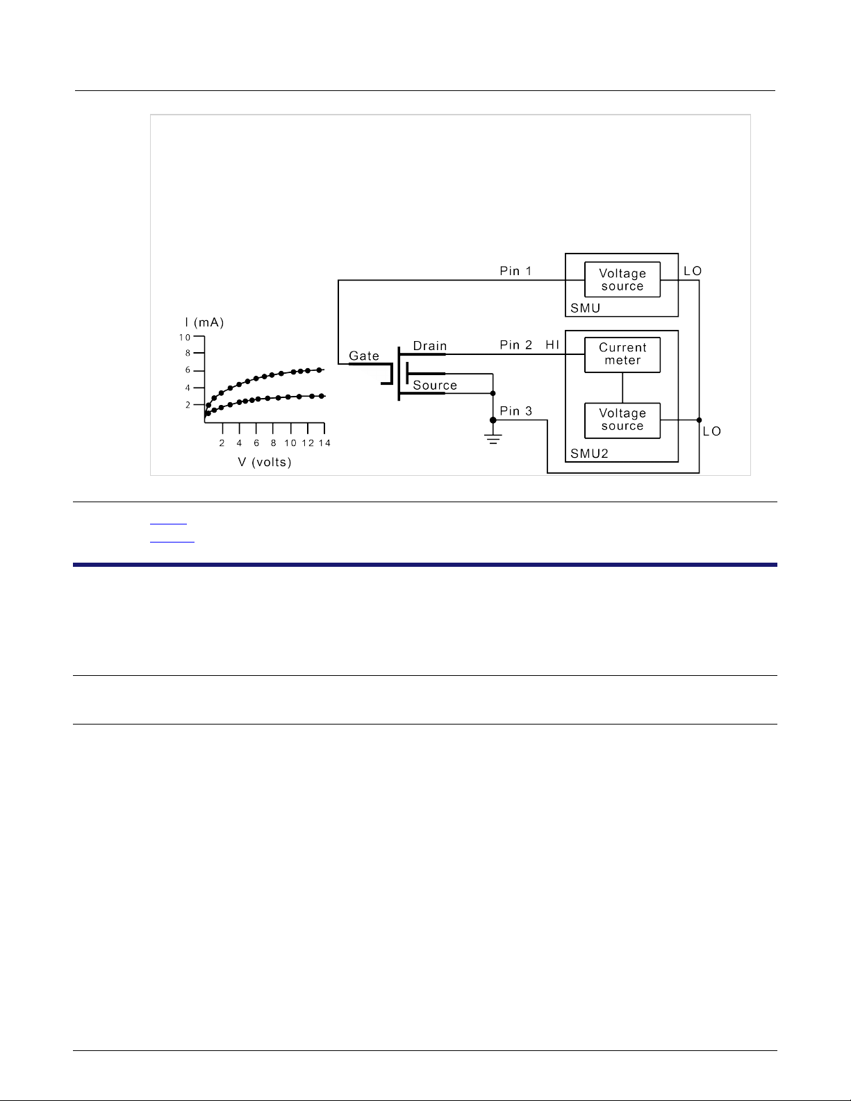
Model 4200A-SCS LPT Library Programming Section 2: LPT commands for general operations
In this example, the sweepX command configures SMU2 to source a voltage that sweeps from 0 V through
+14 V in 14 steps. The results of the first sweepv comman d ar e stored in an arr ay called res1. Because
of the clrscn command, the data and pointers associated with the first sweepv command are cleared.
Then 5 V is forced to the gate, and the measurement process is repeated. Results from these second
measurements are stored in an array called res2.
This example gets the measurement data needed to create a graph showing the gate voltage-to-drain
current characteristics of a field-effect transistor (FET). The program samples the current generated by
SMU2 14 times. This is done in two phases: First with 4 V applied to the gate, and then with 5 V applied.
The gate voltages are generated by SMU1.
Also see
execut (on page 2-8)
sweepX (on page 4-29)
clrtrg
This command clears the user-selected voltage or current level that is used to set trigger points. This permits the
use of the trigXl or trigXg command more than once with different levels in a single test sequence.
Usage
int clrtrg(void);
Details
The searchX, sweepX, asweepX, or bsweepX command, each with different voltage or current
levels, may be used repeatedly within a command if each is separated by a clrtrg command.
4200A-LPT-907-01 Rev. C March 2023 2-3

Section 2: LPT commands for general operation s Model 4200A-SCS LPT Library Programming
double forcur[11], revcur[11]; /* Defines arrays. */
/* each 5 ms in duration. */
This example collects data and creates a graph that shows the forward and reverse conduction
Example
.
.
conpin(SMU1, 1, 0);
conpin(GND, 2, 0);
trigil(SMU1, 5.0e-3); /* Increase ramp to I = 5 mA.*/
smeasi(SMU1, forcur); /* Measure forward */
/* characteristics; */
/* return results to forcur */
/* array. */
sweepv(SMU1, 0.0, 0.5, 10, 5.0e-3); /* Output */
/* 0 V to 0.5 V in 11 */
/* steps, each 5 ms duration. */
clrtrg(); /* Clear 5 mA trigger point. */
clrscn(); /* Clear sweepv. */
trigil(SMU1, -0.5e-3); /* Decrease ramp to */
/* I = -0.5 mA. */
smeasi(SMU1, revcur); /* Measure reverse */
/* characteristics; */
/* return results to revcur */
/* array. */
sweepv(SMU1, 0.0, -30.0, 10, 5.00e-3); /* Output */
/* 0 V to -30 V in 11 steps */
characteristics of a diode. The clrtrg command allows multiple triggers to be programmed twice in the
same test sequence. Each result is returned to a separate array.
Also see
asweepX (on page 4-2)
bsweepX (on page 4-7)
searchX (on page 2-29)
sweepX (on page 4-29)
trigXg, trigXl (on page 2-37)
2-4 4200A-LPT-907-01 Rev. C March 2023

Model 4200A-SCS LPT Library Programming Section 2: LPT commands for general operations
n
double ir4;
/* result to ir4. */
This example measures the leakage current of a variable-capacitance diode. SMU1 applies 60 V across
delay
This command provides a user-programmable delay in a test sequence.
Usage
int delay(long n);
The duration of the delay in milliseconds
Details
Example
The delay command can be called anywhere in the test sequence.
.
.
conpin(SMU1, 1, 0);
conpin(GND, 2, 0);
forcev(SMU1, 60.0); /* Generate 60 V from SMU1. */
delay(20); /* Pause for 20 ms. */
measi(SMU1, &ir4); /* Measure current; return */
the diode. This device is always configured in the reverse bias mode, so the high side of SMU1 is
connected to the cathode. Because this type of diode has very high capacitance and low leakage current,
a 20 ms delay is added. After the delay, current through SMU1 is measured and stored in the variable IR4.
Also see
4200A-LPT-907-01 Rev. C March 2023 2-5
rdelay (on page 2-26)